

Page 1
Page 2

Page 3

Foreword
Dear Customer
These instructions are intended to help you to repair the electronic Diesel control system properly.
In writing these instructions, we have assumed that you have the necessary knowledge of control systems
for working on and with the electronic diesel control.
Important instructions which concern technical safety and protection of persons are emphasised as shown
below.
Caution:
This refers to working and operating procedures which must be complied with in order to prevent
damage to or destruction of material.
Note:
Explanations useful for understanding the working or operating procedure to be performed.
Best regards
MAN Nutzfahrzeuge Aktiengesellschaft
Nuremberg Plant
Since our products are in continuous development, we reserve the right to make technical modifications.
2003 MAN Nutzfahrzeuge Aktiengesellschaft
Reprint, duplication or translation, as a whole or in part without the written approval of MAN is prohibited.
MAN reserves all rights accorded by the relevant laws on copyright.
MTDA Technical status: 09.2002 51.99598-8112
1
Page 4

Contents
Foreword 1 . . . . . . . . . . . . . . . . . . . . . . . . . . . . . . . . . . . . . . . . . . . . . . . . . . . . . . . . . . . . . . . . . . . . . . . . . . . . . . . .
Safety information 3 . . . . . . . . . . . . . . . . . . . . . . . . . . . . . . . . . . . . . . . . . . . . . . . . . . . . . . . . . . . . . . . . . . . . . . . .
Electronic Diesel Control 5 . . . . . . . . . . . . . . . . . . . . . . . . . . . . . . . . . . . . . . . . . . . . . . . . . . . . . . . . . . . . . . . . . .
System description 6 . . . . . . . . . . . . . . . . . . . . . . . . . . . . . . . . . . . . . . . . . . . . . . . . . . . . . . . . . . . . . . . . . . . . . . .
Component description 8 . . . . . . . . . . . . . . . . . . . . . . . . . . . . . . . . . . . . . . . . . . . . . . . . . . . . . . . . . . . . . . . . . . . .
Control unit plug connector 8 . . . . . . . . . . . . . . . . . . . . . . . . . . . . . . . . . . . . . . . . . . . . . . . . . . . . . . . . . . . . . . . . .
MS 5 injection pump 10 . . . . . . . . . . . . . . . . . . . . . . . . . . . . . . . . . . . . . . . . . . . . . . . . . . . . . . . . . . . . . . . . . . . . . .
MS 5 Electromagnetic fuel volume regulator 11 . . . . . . . . . . . . . . . . . . . . . . . . . . . . . . . . . . . . . . . . . . . . . . . . . .
Control-slider adjusting mechanism 12 . . . . . . . . . . . . . . . . . . . . . . . . . . . . . . . . . . . . . . . . . . . . . . . . . . . . . . . . .
Resistor bank 13 . . . . . . . . . . . . . . . . . . . . . . . . . . . . . . . . . . . . . . . . . . . . . . . . . . . . . . . . . . . . . . . . . . . . . . . . . . . .
Redundant cut-out device Safety relay 13 . . . . . . . . . . . . . . . . . . . . . . . . . . . . . . . . . . . . . . . . . . . . . . . . . . . . . . .
Drive stage selection 14 . . . . . . . . . . . . . . . . . . . . . . . . . . . . . . . . . . . . . . . . . . . . . . . . . . . . . . . . . . . . . . . . . . . . . .
Charge-air, coolant and fuel temperature sensors 15 . . . . . . . . . . . . . . . . . . . . . . . . . . . . . . . . . . . . . . . . . . . . .
Charge-air pressure sensor (51.27421-0181) 16 . . . . . . . . . . . . . . . . . . . . . . . . . . . . . . . . . . . . . . . . . . . . . . . . .
RPM sensor 17 . . . . . . . . . . . . . . . . . . . . . . . . . . . . . . . . . . . . . . . . . . . . . . . . . . . . . . . . . . . . . . . . . . . . . . . . . . . . .
Injector and needle movement sensor 18 . . . . . . . . . . . . . . . . . . . . . . . . . . . . . . . . . . . . . . . . . . . . . . . . . . . . . . .
Notes on operation 19 . . . . . . . . . . . . . . . . . . . . . . . . . . . . . . . . . . . . . . . . . . . . . . . . . . . . . . . . . . . . . . . . . . . . . . .
Self-diagnosis 20 . . . . . . . . . . . . . . . . . . . . . . . . . . . . . . . . . . . . . . . . . . . . . . . . . . . . . . . . . . . . . . . . . . . . . . . . . . . .
Check-list 23 . . . . . . . . . . . . . . . . . . . . . . . . . . . . . . . . . . . . . . . . . . . . . . . . . . . . . . . . . . . . . . . . . . . . . . . . . . . . . . .
Troubleshooting chart 26 . . . . . . . . . . . . . . . . . . . . . . . . . . . . . . . . . . . . . . . . . . . . . . . . . . . . . . . . . . . . . . . . . . . . .
Troubleshooting program 29 . . . . . . . . . . . . . . . . . . . . . . . . . . . . . . . . . . . . . . . . . . . . . . . . . . . . . . . . . . . . . . . . . .
Testing 30 . . . . . . . . . . . . . . . . . . . . . . . . . . . . . . . . . . . . . . . . . . . . . . . . . . . . . . . . . . . . . . . . . . . . . . . . . . . . . . . . . .
Plug connections 64 . . . . . . . . . . . . . . . . . . . . . . . . . . . . . . . . . . . . . . . . . . . . . . . . . . . . . . . . . . . . . . . . . . . . . . . . .
EDC diagnostic tools 66 . . . . . . . . . . . . . . . . . . . . . . . . . . . . . . . . . . . . . . . . . . . . . . . . . . . . . . . . . . . . . . . . . . . . . .
MAN-Cats Diagnostics System 67 . . . . . . . . . . . . . . . . . . . . . . . . . . . . . . . . . . . . . . . . . . . . . . . . . . . . . . . . . . . . .
MAN-Cats - Software Description 69 . . . . . . . . . . . . . . . . . . . . . . . . . . . . . . . . . . . . . . . . . . . . . . . . . . . . . . . . . .
Rating data sheet 85 . . . . . . . . . . . . . . . . . . . . . . . . . . . . . . . . . . . . . . . . . . . . . . . . . . . . . . . . . . . . . . . . . . . . . . . .
EDC-Connection diagram 93 . . . . . . . . . . . . . . . . . . . . . . . . . . . . . . . . . . . . . . . . . . . . . . . . . . . . . . . . . . . . . . . . .
Electronic Diesel Control -Description of inputs and outputs 95 . . . . . . . . . . . . . . . . . . . . . . . . . . . . . . . . . . . .
Electronic Diesel Control -Guidelines for Preparing Wiring Harnesses 119 . . . . . . . . . . . . . . . . . . . . . . . . . . .
Plug connections 129 . . . . . . . . . . . . . . . . . . . . . . . . . . . . . . . . . . . . . . . . . . . . . . . . . . . . . . . . . . . . . . . . . . . . . . . . .
Notes on design and assembly for wiring harnesses of electronic systems 131 . . . . . . . . . . . . . . . . . . . . . . .
Cable cross-section 134 . . . . . . . . . . . . . . . . . . . . . . . . . . . . . . . . . . . . . . . . . . . . . . . . . . . . . . . . . . . . . . . . . . . . . . .
Engine electrics 137 . . . . . . . . . . . . . . . . . . . . . . . . . . . . . . . . . . . . . . . . . . . . . . . . . . . . . . . . . . . . . . . . . . . . . . . . . .
Flamme starter 139 . . . . . . . . . . . . . . . . . . . . . . . . . . . . . . . . . . . . . . . . . . . . . . . . . . . . . . . . . . . . . . . . . . . . . . . .
Sensores and limit-value switch 149 . . . . . . . . . . . . . . . . . . . . . . . . . . . . . . . . . . . . . . . . . . . . . . . . . . . . . . . . . .
Connection diagram 157 . . . . . . . . . . . . . . . . . . . . . . . . . . . . . . . . . . . . . . . . . . . . . . . . . . . . . . . . . . . . . . . . . . . .
Connection diagram monitoring 158 . . . . . . . . . . . . . . . . . . . . . . . . . . . . . . . . . . . . . . . . . . . . . . . . . . . . . . . . . .
Index 159 . . . . . . . . . . . . . . . . . . . . . . . . . . . . . . . . . . . . . . . . . . . . . . . . . . . . . . . . . . . . . . . . . . . . . . . . . . . . . . . . . . .
2
Page 5

Safety information
ËË
General
Important safety regulations are summarized in this quick-reference overview and arranged by topic to effectively convey the knowledge necessary to avoid accidents causing injury, damage or environmental hazard.
The engine operating manual contains further information.
Important:
Should an accident occur despite all precautionary measures, particularly one involving contact with corrosive acid, penetration of fuel under the skin, scalding by hot oil, antifreeze splashing into the eyes etc. you
must seek medical assistance immediately.
1. Instructions for avoiding accidents likely to cause injury
Only authorized and qualified personnel are permitted to carry out inspection, adjustment and repair work
D Secure and chock vehicles to prevent the vehicle rolling
D Firmly secure units and assemblies on disassembly
D Only authorized personnel are permitted to start and operate the engine
D Do not stand too close to rotating parts while the engine is running
Wear close-fitting working clothes
D Do not touch a hot engine with bare hands:
Risk of burns
D Keep area surrounding engine, ladders and stairways free of oil and grease.
Accidents caused by slipping can have serious consequences
D Only work with tools which are in good condition. Damaged or worn spanners and
wrenches can slip off: Risk of injury
D Persons must not stand under an engine suspended on a crane hook. Keep lifting gear
in perfect condition
D Only open coolant circuit once the engine has cooled down. Follow the instructions
given under “Care and Maintenance” in the Operating Manual exactly if it is not possible
to avoid opening the coolant circuit with the engine at operating temperature
3
Page 6

Safety information
D Do not tighten or loosen pipes and hoses that are under pressure (lubricant circuit,
coolant circuit and any downstream hydraulic oil circuits): Risk of injury caused by
liquids escaping under pressure
D Do not place hands under the fuel jet when checking injection nozzles.
Do not inhale fuel mist
D Always disconnect battery when working on the electrical system
D Do not use rapid charger to start the engine. Rapid charging of batteries is only per-
mitted with the positive and negative leads disconnected!
D Disconnect batteries only with the ignition turned off
D Observe manufacturer’s instructions for handling batteries.
Caution:
Battery acid is toxic and corrosive. Battery gasses are explosive
D Only use suitable measuring instruments to measure voltages! The minimum input
resistance of a measuring instrument should be 10 MΩ
D Only disconnect or connect wiring harness connectors on electronic control units with
the ignition turned off!
Disconnect batteries and connect the positive lead to the negative lead such that they are
electrically conductive before carrying out any electric welding work. Earth the welding set
as close to the weld as possible. Do not place cables of welding set parallel to electrical
lines in the vehicle.
Refer to the “Welders Code of Practice” for further accident prevention measures.
D When carrying out repaint jobs, electronic components may be subject to high tem-
peratures (max. 95°C) for only very short periods; a period of up to approx. 2 hours is
permissible at a max. temperature of 85°C, disconnect batteries
Limitation of liability for parts and accessories
In your own interest, we strongly recommend you use only accessories and original MAN parts expressly
approved by MAN for your MAN engine. The reliability, safety and suitability of these parts and accessories
have been tested specially for MAN engines. Despite us keeping a constant eye on the market, we cannot
assess and be held responsible for these properties in other products, even if they bear TÜV (German testing and inspection institute) approval or any other official approval in any particular case.
Laying up or storage
Special measures must be implemented in accordance with MAN Company Standard M 3069 Part 3 if engines are to be laid up or placed into storage for more than 3 months.
4
Page 7

Electronic Diesel Control
Electronic Diesel Control EDC
General
The requirements set by customers and legislation in respect of fuel consumption, exhaust emission and
noise characteristics etc. on Diesel engines have grown over the years and will be even more stringent in
the future.
The fact that conventional mechanical injection systems have reached their performance limits has made
electronically controlled fuel injection systems necessary.
Such systems increase engine efficiency, improve driving comfort and lessen the burden on the environment.
EDC (Electronic Diesel Control) meets these requirements.
5
Page 8

System description: EDC MS5
System description
Engine
speed 1
Engine
speed 2
Charge air
temperature
Needle movement sensor
Boost
pressure
Safety relay
Power supply
Fuel temperature
Coolant
temperature
Control
unit
Intermediate engine
terminal 30
Terminal 15
PWM signal
speeds
ISO diagnosis
Diagnosis request
Idle speed setting
Diagnosis
warning lamp
CAN bus
Throttle
lever signal
The engine can be triggered
- elektrically with the 2,9 - 4,5V signal or alternatively CAN bus
The controller contains
- the linear solenoid
- the control rod position transducer
The linear solenoid is actuated by the electronic control unit.
The control unit processes information which it receives via
- the control rod position transducer
- the drive position selection
- charge-air pressure sensor
- coolant temperature sensor
- charge-air temperature sensor
- the engine rpm sensors
- the needle movement sensor
- and the fuel temperature sensor (in the injection pump).
The diagnosis request pushbutton and the EDC indicator lamp are used in detecting faults and signalling
them through a code.
An ISO interface provides a communication with the MAN-cats test and diagnostic computer.
The control unit, with its program adapted to the engine model concerned, determines the optimum setting
of the control rod from all the measured values.
To ensure the vehicle can reach the nearest workshop in the event of one or several sensors failing, an
emergency operation function is integrated in the control unit which, depending on the situation, enables
the vessel to continue on its way, albeit with restricted functions.
When the brakes are applied, the system operates as an intermediate engine speed controller with a proportional degree of 0, i.e. a set intermediate engine speed is maintained exactly provided the engine develops sufficient power output for this purpose.
6
Page 9

System description
The idle speed control operates in the same way as the intermediate engine speed control. The idle speed
is exactly maintained by means of the idle speed governor as long as the engine output is sufficient for this.
The regulated idle speed can be varied within certain limits.
Starting-fuel delivery is output when either a lower start recognition speed is exceeded. The starting fuel
volume and cold idle speed are limited as a function of the coolant temperature to avoid impermissible
smoke emission and unnecessary revving of the engine after starting.
7
Page 10

Component description
Control unit plug connector
Pinouts
19 1. . . . . . . . . . . . . . . . . . . . . . .
37 20. . . . . . . . . . . . . . . . . . . . . .
55 38. . . . . . . . . . . . . . . . . . . . . .
Pin assignments of control unit plug connector
EDC Pin Connection to component (O=Output, I=Input)
1 Injection pump controller pin 8 O
Jumper to pin 2 (activation of fuel volume regulator) O
2 Jumper to pin 1 (activation of fuel-delivery regulator) O
3 Control-slide mechanism
4 Control-slide mechanism
5 Not used
6 Not used
7 Not used
8 Not used
9 Injection pump controller pin 5 (control rod position sensor, instrument coil)
10 Injection pump controller pin 1 (control rod position sensor, reference coil)
11 Injection pump controller pin 6 (control rod position sensor, centre pick-off)
12 Not used
13 Negative from control unit for (Sensor ground)
- rpm sensor
- charge-air pressure sensor
- drive stage selection
- charge-air temperature sensor
- coolant temperature sensor
- resistor bank
- fuel temperature sensor
14 Safety-relay O
15 Control unit power supply battery + (via main relay and fuse) I
16 Control unit power supply battery + (via main relay and fuse) I
17 Earth for auxiliary rpm sensor and needle movement sensor
18 Power supply battery 19 Power supply battery 20 EDC indicator lamp and diagnostic lamp O
21 RPM sensor (twisted with cable pin 13) I
22 Auxiliary rpm sensor (twisted with cable pin 17) I
23 Intermediate engine speed control ZDR 1 I
24 Not used
8
Page 11

Component description
EDC Pin Connection to component (O=Output, I=Input)
25 Not used
26 Not used
27 Drive stage selection (signal) I
28 Engine speed signal output from control unit (square-wave pulses) O
29 Multiplex signal O
30 CAN-L
31 CAN-H
32 Needle movement sensor (signal)
33 Charge-air pressure sensor (supply) O
34 Fuel temperature sensor I
35 Resistor bank
36 Turbo pressure sensor (signal) I
37 Not used
38 Not used
39 Empty fuel switch signal
40 External engine cut-out
41 Intermediate engine speed control ZDR 2 I
42 Not used
43 Not used
44 Resistance group I
45 Drive stage selection (supply)
46 Relay power supply batt.+ (main relay) O
47 Relay power supply n/o contact I
48 Diagnostic connection (K-link)
49 Diagnostic connection (L-link)
50 Not used
51 Resistor bank 3 kW
52 Assigned to batt.+ (to enable multiplex signal) I
53 Coolant temperature sensor I
54 Resistance group
55 Turbo air temperature sensor I
9
Page 12
Component description
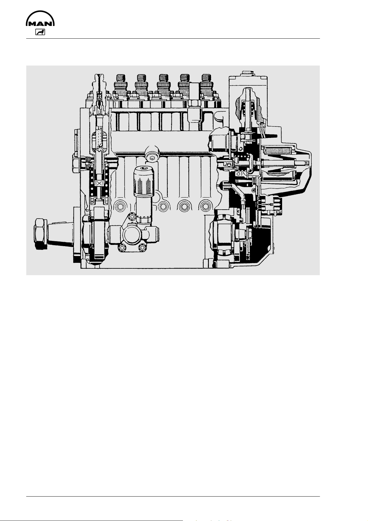
MS 5 injection pump
The MS 5 injection pump, also known as a “control-slide pump” has a mechanism which regulates the start
of injection by performing a “lifting / sliding” movement. The pump comprises a heavy-duty conventional
injection module, as used on the familiar P-pumps, a flange-mounted electromagnetic fuel volume regulator, in place of the mechanical regulator, and an electromagnetic regulator for the start of injection (pilot
stroke / start of delivery regulator).
The difference between this system and the familiar P-pump is primarily in the plunger.
10
Page 13

Component description
MS 5 Electromagnetic fuel volume regulator
1
2
3
4
5
6
1 Actuating solenoid for start of delivery 4 Control rod position sensor
2 Control-slider adjusting shaft 5 Electrical connection
3 Control position actuating solenoid 6 Plate for blocking start of delivery
and part of the oil pressure delivery pump
The fuel volume regulator works in the same way as the familiar EDC-RE regulators which use the P-pump
(MS 5). The most important component of the fuel-delivery regulator is a linear solenoid whose armature
acts directly on the control rod thus determining the injection volume by means of the control position.
When no current is supplied, the control rod is held in the stop position by means of a spring.
The pilot feed / start of delivery regulator also contains a linear solenoid, whose armature, by means of an
adjusting lever, causes the control-slider adjusting shaft to rotate. When no current is supplied, the adjusting shaft is also held in position by a spring, so that the control-slider is in its uppermost position, in the
“late” start of delivery position.
The regulator also has a control rod position sensor and an oil pump (viscous pump).
PIN:
Designation:
4
3
5
8
2
6
1
7
Control rod position sensor
Actuating solenoid
Actuating solenoid
2
free
RWG M
RWG Y
RWG R
Q
Start of injection
MES 1
MES 0
3478561
MVS 1
MVS 0
11
Page 14

Component description
Control-slider adjusting mechanism
1
2
3
4
1 Pump plunger 3 Control-slider adjusting shaft
2 Control-slider 4 Control rod
The difference between this system and the P-pump is primarily in the pumping element. The element cylinder contains a window and a control-slider which slides on the element plunger. The control-slider contains the control bore for the start and end of delivery. Because the control-slider can be height-adjusted,
the start and end of delivery can be changed.
The pump housing contains a rotating adjusting shaft with drivers which engage in a groove on the controlslider. When the shaft is rotated, the height of all the control-sliders is adjusted evenly, thereby changing
the pilot stroke and the start of delivery.
12
Page 15

Component description
Resistor bank
On commercial vehicles, certain items of data are fed to the EDC which are not required for railway operation.
An example of such data is a signal from the tachograph (speedometer, tachograph) which is used for controlling or limiting the driving speed (see Page 36).
Some unused EDC connections must be closed by resistors since the EDC constantly conducts a signalrange check, as described on Page 20.
Interior circuit
3
1
2
5
6
4
R1 0.511 kOhm
R5 0.511 kOhm
R2 1.37 kOhm
R6 1.37 kOhm
R7 3.08 kOhm
R3 3.08 kOhm
R8 8.20 kOhm
R4 8.20 kOhm
8
9
7
2 84357691
Redundant cut-out device Safety relay
The relay (redundant cut-out device) is a safety-critical component.
If certain faults occur in the EDC system the relay interrupts the voltage supply for the control-rod travel
operating magnet.
The control rod is pulled back to the stop position by a return spring.
The safety relay is under current throughout operation. To activate it (e.g. emergency switch-off of the en-
gine) the EDC control unit interrupts the current circuit.
13
Page 16

Component description
Drive stage selection
Function
The drive stage selection device transfers driver’s requests in the form of voltages to the control unit. The
control unit then derives the corresponding engine speed or volumetric charge from these voltages.
Block diagram
Pin 13
Pin 39
Pin 13
Pin 27
U = Reference voltage, approx. 5 V from the EDC control unit
u = Setpoint
Pedal travel sensor simulation values
Upper idle speed: 257-539 V / high idle speed 2944-4501 mV
Empty fuel switch: switch-on point at 569-976 mV (typically 800 mV)
top idle
speed
Pin 45
lower idle
speed
257 mV 976 mV 2944 mV 4501 mV [ mV ]
539 mV 569 mV
Fault registration
Empty fuel switch range
(typically 880 mV)
Exceptionally, the voltage “u” is produced electronically as drive position selection, or the setpoint selection
(drive position selection) takes place via the CAN bus.
14
Page 17

Charge-air, coolant and fuel temperature sensors
Charge-air B197 (51.27421-0165)
Characteristic R=f (-í)
Component description
2
4
3
1
Plug connection
Coolant / Fuel B124 (51.27421-0172)
Characteristic R=f (-í)
2
4
3
1
Plug connection
Function
The temperature sensors for charge air, coolant and fuel are NTC resistors.
The coolant temperature sensor is located in the coolant circuit and the turbo air temperature sensor in the
turbo air circuit after the intercooler. They supply the control unit with information relating to the coolant and
turbo air temperature.
The fuel temperature sensor is part of the injection pump and measures the fuel temperature for determination of the fuel density.
Depending on the fuel density the control unit determines the injection quantity and thus also the duration
of injection.
15
Page 18

Component description
Charge-air pressure sensor (51.27421-0181)
1
Ground - Supply +
Plug connection
Function
The pressure sensor element consists of an Si-diaphragm which contains several piezo-resistive (pressuresensitive) semiconductor resistors. The pressure to be measured “deflects” the sprung diaphragms. As a
result, extended or compressed zones are created on the surface of the diaphragms. The action of these
forces changes the electrical ratings of semiconductor resistor arrays arranged in these zones. These values are a measure for the pressure to be measured.
Curve
(VDC)
4.650 MIN
4,500
4
32
Output
Overpressure
0,500
0.350 MIN
Vacuum
0,5 4,0
VS
16
Pressure (bar)
Page 19

Component description
RPM sensor
Housing: grey
Coding A
Function
The rpm sensor consists of a permanent magnet and a coil with a high number of windings. The magnet
“touches” the rotaring component to be measured, normally a crown gear or grooved ring gear; with its
magnetic field.
With the EDC MS5 system, there are 6 grooves on the flywheel.
When a groove passes the sensor, the magnetic current is reduced. This generates an induction voltage in
the sensor coil which is measured by the electronic control. The distance between the sensor and the
grooved ring gear is approx. 1 mm.
Two rpm sensors are required to ensure reliable operation of the EDC system.
Both rpm sensors are installed in the flywheel housing.
A distinction is made between the rpm sensor and the auxiliary rpm sensor.
The rpm sensor is installed in the flywheel housing such that an rpm pulse is triggered 10°after TDC.
The auxiliary rpm sensor is installed in the flywheel housing in such a way that an auxiliary speed pulse is
triggered 18° after TDC. The signals of the auxiliary rpm sensor are used only for redundant engine speed
sensing.
2
Plug connection
RPM sensor (1)
1
21
Plug connection
Auxiliary rpm sensor
(2)
Housing: black
Coding B
Caution:
Do not confuse installation locations of the rpm sensor (1) and the auxiliary rpm sensor (2), nor
the “+” and “-” wires of the sensors.
17
Page 20

Component description
Injector and needle movement sensor
1
2
12
Plug connection
1 Coil
2 Pressure pin
The needle movement sensor records the start of injection using a sensor which is incorporated directly
into the injector holder. This sensor, through its detection of the needle movement, is used to calculate the
fuel injection timing.
18
Page 21

Notes on operation
Start procedure
The gear stage must be selected (idle speed request setpoint specification) to start the engine.
Changing idle speed
Idle speed setting is possible using EOL programming (MAN Cats), but this should only be performed by
MAN customer service personnel.
Intermediate engine speed control
Different intermediate engine speeds can be programmed by means of MAN-Cats:
D ZDR 1, ZDR 2 and ZDR 3
These intermediate engine speeds are set by corresponding pin connection.
The intermediate engine speeds can be changed using EOL programming (MAN-Cats), but this should only
be performed by MAN customer service personnel.
19
Page 22

Self-diagnosis
General
The EDC system continuously checks itself. It does this by running a signal-range check. During this
check, all signals are scanned for presence and plausibility within a certain time frame (determined by the
software).
The control unit itself is also constantly checked the whole time the program is running. The first check is
always carried out when the ignition is turned on.
Any faults occurring during operation are stored for the purpose of subsequent diagnosis.
A maximum of 5 faults can be stored simultaneously in the fault memory. The faults are stored in the order
in which they occurred. If more than 5 faults occur, the least significant fault is deleted.
Fault storage includes
D allocation of fault priority,
D identification of the type of fault,
D recording of fault frequency.
Sporadic faults are recorded by a frequency counter the first time they occur. This means that a certain frequency number is set which is decremented by one during every start procedure. If the fault no longer occurs, it is deleted when the counter reaches zero.
To report the fault, the diagnostic lamp either comes on permanently or remains off, depending on the significance of the fault. If several faults are stored, the steady light has priority over OFF.
Only faults currently present are indicated. Faults which are stored but which are not currently present are
not indicated.
There are two fault memories:
D Fault memory for diagnosis via ISO interface. This memory can be read out and cleared with MAN-Cats
D Fault memory for diagnosis via flash code. The flash code memory can be read out and cleared with the
aid of the diagnosis button.
Faults are always entered in both fault memories simultaneously and can be read out even after the ignition
has been switched off and back on again.
Indicator lamp check:
The EDC indicator lamp lights as a lamp test for approximately 2 seconds after the ignition is switched on.
20
Page 23

Self-diagnosis
The following measures are implemented automatically depending on the significance of the fault:
D Changeover to suitable substitute function to enable continued yet restricted operation
D Reduction of engine speed to idle speed (drive stage 0)
D Immediate shut-down of the engine if required for safety reasons. Depending on the type of fault, engine
shut-down is done by reducing the fuel delivery volume to zero or by way of an emergency shut-down
with safety relay.
Flash code
To read out the fault memory
D With the engine stationary or running and the “ignition“ switched on, press and hold the diagnosis re-
quest button for at least 2 seconds. The diagnosis lamp will not come on
D The flash procedure starts after a pause of approximately 3 seconds. The flash code is divided into long
and short pulses
D The diagnostic system always outputs only one fault at a time. In order to check whether several faults
are stored, the fault scanning procedure must be repeated until the fault that was shown first reappears
Example of a flash code output
On
Lamp
Off
20
18/19
49
0.5 sec
Fault 2x long, 5x short
OFF phase before output: 3 seconds
ON duration of a long pulse: 2 seconds
OFF phase between two long pulses: 1 second
OFF phase between long and short pulses: 5 seconds
ON duration of a short pulse: 0,5 seconds
OFF phase between two short pulses: 0,5 seconds
To clear fault memory
1. Press request button
2. Switch on ignition
3. Press and hold request button for a further 3 seconds but not longer than 10 seconds
21
Page 24

Self-diagnosis
R
Fault code output MAN MS5 EDC
Overview of flash codes
Number of
flashes
Long Short
0 0 No fault stored
1 1 11h Fuel temperature sensing No 1 3 13h Undervoltage No 1 6 96h Control unit (computer coupling) Yes a)
1 7 17h Overrevving Yes b)
1 8 18h Start of injection control deviation Yes b)
1 10 1AH Needle movement sensor No 1 12 1CH Resistor bank control unit pin 35 No 1 13 1DH Control box Yes b)
1 15 1FH Control unit (CAN-System) No 2 5 25h Main relay Yes b)
2 7 A7H Resistance bank, control unit pin 54 Yes b)
2 8 A8H Atmospheric pressure sensing Yes b)
2 13 2DH FM message Yes b)
3 1 31h Safety relay No 3 2 32h EEPROM processor 1 error No 3 3 33h EEPROM processor 2 error No 3 4 34h Stop-extern-input No 3 6 36h Intercooler Yes b)
3 7 37H * Output stage error No 3 8 38h Afterrunning not completed No 3 9 39H Afterrunning watchdog error No 3 10 3AH Control rod position sensor - loose contact No 3 11 3BH * AGR-Fault (control deviation) Yes b)
* MS5 stage 5
a) Reset by “Ignition” Off / On (cold restart)
b) Reset takes place automatically once the fault is rectified
Fault code Fault path Steady
light fault
1 81h Pedal value transmitter / Drive stage selection Yes b)
3 83h Boost air temperature sensing Yes b)
4 84h Engine speed sensing (primär) Ye s b)
5 85h Boost pressure sensor Yes b)
6 86h Control rod position sensing Yes a)
7 87h Coolant temperature sensing Yes b)
10 8AH Fuel volume regulator monitoring Yes a)
14 8EH Auxiliary rpm sensor Yes b)
Maintai-
ned light
eset
a) / b)
22
Page 25

Check-list
1. Resistance checks
- Engine stop, ignition off
- Engine temperature ≈ 25°C
- Control unit not (!!!) connected, cable harness adapter connected
- Measure resistance between PIN+ and PIN- with multimeter
Component
Control rod position sensor
RPM sensor (DZG) 21 13 0,8–1,0 kΩ kΩ
Auxiliary rpm sensor (HZG) 22 17 0,8–1,0 kΩ kΩ
Fuel-delivery regulator
Control-slide mechanism
Ground 13 18 >10 MΩ MΩ
Needle movement sensor 32 17 90–130 Ω Ω
Safety relay 14 19 200–300 Ω Ω
À
Ã
Â
PIN+ PIN- Setpoint Measured value Remark
11 9 18–25 Ω Ω
11 10 18–25 Ω Ω
18 9 >10 MΩ MΩ
18 10 >10 MΩ MΩ
15 1 0,7–1,3 Ω Ω
18 1 >10 MΩ MΩ
16 2 0,7–1,3 Ω Ω
15 3 1,2–2,0 Ω Ω
18 3 >10 MΩ MΩ
16 4 1,2–2,0 Ω Ω
17 19 >10 MΩ MΩ
AGR-input
AGR-output
Coolant temperature sensor 53 13 1,3–3,6 kΩ kΩ
Fuel temperature sensor 34 13 1,3–3,6 kΩ kΩ
Boost pressure sensor 55 13 1,3–3,6 kΩ kΩ
Multistage switch neutral 35 13 500–520 Ω Ω
Â
Â
Torque reduction active 35 13 1,2–1,5 kΩ kΩ
Speed reduction active 35 13 7,6–9,0 kΩ kΩ
7 18 39–49 Ω Ω
15 24 < 1 Ω Ω
À Exact measurements are possible only at defined temperatures
Á Engine operating temperature ~80°C resistor approx. 230–460 Ω
 EURO 3 - engine only
à Safety relay (K324): For measurement of resistor take of the relay and connect contact 30 and 87.
2. Speed measurement
- Engine running
- Coolant temperature >30°C
- Wiring harness adapter connected
- EDC control unit connected
- Checking with MAN-Cats monitoring 2
Sensor Setpoint Measured speed Remark MAN-Cats
rpm sensor Low Idle speed rpm Drive signal min. Engine speed
High Idle speed rpm Drive signal max. (Monitoring 2)
Auxiliary rpm sensor Low Idle speed rpm Drive signal min. Engine speed
High Idle speed rpm Drive signal max. (Monitoring 2)
23
Page 26

Check-list
3. Voltage measurement
- Engine running
- Measure voltage between PIN+ and PIN - with multimeter
Component PIN+ PIN- Setpoint Measured value Remark Engine speed
Battery voltage 15 18 U-Bat V V Low idle
(U-Bat) 47 19 U-Bat V V Low idle
Reference voltage 45 13 4,75–5,25 V V Low idle
33 13 4,75–5,25 V V Low idle
Drive signal /
Pedal position
Idle speed switch
Fuel temperature
sensor
Coolant temperature
sensor
Charge-air
temperature sensor
Charge-air pressure 36 13 0,94–1,20 V V 0 – 0,1 bar Low idle
sensor 36 13 1,10–1,70 V V 0,3 – 0,6 bar High idle
Ä
Ä Not in case of CAN control
27 13 0,30–0,42 V V Min. Low idle
27 13 2,90–4,50 V V Max. High idle
Ä
39 13 4,5–5,25 V V Min. Low idle
39 13 0–2,0 V V Max. High idle
34 13 4,17–2,62 V V 10 – 50°C Low idle
53 13 3,46–1,22 V V 30 – 90°C Low idle
55 13 4,17–2,62 V V 10 – 50°C Low idle
4. Check main relay
- Measure voltage between PIN+ and PIN- with multimeter
- Pin 46 must switch to U-Batt within 0.5 to 5 seconds after ignition has been switched off
Component PIN+ PIN- Setpoint Measured value Remark Engine speed
Main relay 47 18 U-Bat V V Ignition
“ON”
47 18 0 V V Ignition
“OFF”
46 18 0 V V Ignition
“ON”
46 18 U-Bat V V Ignition
“OFF”
Low idle
0
Low idle
0
5. ZDR-Intermediate engine speed control test
- Wiring harness adapter connected
- EDC control unit connected, engine running
- Connection between PIN 15 and PIN 23 and / or PIN 41
Intermediate engine
speed control
ZDR 1 24 V 0 V rpm rpm
ZDR 2 0 V 24 V rpm rpm
ZDR 3 24 V 24 V rpm rpm
Pin 23 Pin 41 Set point (EOL) Measured value Remark
24
Page 27

Check-list
6. Flash code diagnosis check
- Wiring harness adapter connected
- EDC control unit connected
- Engine running
Check procedure
Short-circuit rpm sensor; connect pin 21 to pin 13 to do this
Diagnosis lamp lights up
Engine speed is measured by auxiliary rpm sensor
Disconnect connection between pin 21 and pin 13
Press diagnosis button for at least 3 seconds but no more than 10 seconds
Check flash code (4x short = rpm sensor)
Deleting the fault memory; do this by turning off ignition pressing diagnosis button, turning on ignition,
pressing and holding button for at least 3 seconds but not longer than 10 seconds
Result:
7. Safety relay check
- Wiring harness adapter connected
- EDC control unit connected
- Engine running
Check procedure
Disconnect pin 14
Engine should shut down after no more than 3 seconds.
Result:
8. Capacitance reserve check
The power capacitance of the line leading to the control rod position transducer must not exceed the specified
maximum capacitance.
The capacitance increases if the line is dirty or moist. This check is designed to establish how much capacitance
reserve is still available.
- Wiring harness adapter connected
- EDC control unit connected
Check procedure
- Connect capacitance decade between pin 11 and pin 13
at wiring harness adapter.
- Connect additional capacitance until the engine no longer starts or MAN-Cats signals the fault “Control rod
position sensor”
Set point >300 pF mit additional capacitance (wiring harness adapter)
- Record value
Result:
9. Deleting the fault memory
The fault code memory must be deleted on completion of the checks. No fault must be stored when the “ignition” is
turned on again.
If this is not the case, the fault must be located and eliminated in accordance with the troubleshooting procedure.
Caution:
If the fault in the fault memory is deleted only via the button, it will continue to be present in the 2nd memory
and indicated by MAN-Cats.
Result:
25
Page 28

Troubleshooting chart
1. EDC self-diagnosis or flash code output
2. Starter turns over engine only slowly or not at all
3. Starter turns, engine does not start, engine does not start / difficult to start when cold
4. Engine stalls (dies) during operation, no longer starts (starter turns),
engine does not start / starts with difficulty when hot
5. . Sudden, temporary engine shut-down, engine does not reach full revs
6. Engine only runs at idle speed, no throttle response
7. Engine only runs at elevated idle speed, no throttle response
8. Rated engine speed distinctly reduced (even under no load)
9. Reduced output in all ranges
10. Irregular engine operation, traction loss
11. Unstable idle speed, engine hunting, misfiring, knocking in engine
12. Engine judder
13. Unusual combustion noise
14. Excessive smoke emission: White smoke / blue smoke
15. Excessive smoke emission: Black smoke
16. Engine temperature too high (coolant loss)
17. Intermediate engine speed control cannot be activated / does not switch off, engine revs too
high
18. Fuel consumption too high
19. Lubricating oil pressure too low
20. Lubricating oil pressure too high
21. Lubricating oil consumption too high
22. Engine too loud / mechanical noise
Possible causes
x x Batteries discharged, battery lead connections loose or corroded,
x Crank gear blocked
x x Starter solenoid switch sticking (clicks) / defective, cable connection loose or dama-
x x Starter / starter interlock relay defective (carbon brushes worked loose / worn,
x x x x Engine oil viscosity unsuitable, not suitable for ambient temperature, lubricating oil
x x Oil level in sump too high
x Oil level in sump too low, oil in sump too thin (mixed with condensate or fuel)
x Engine temperature too high
x Oil filter clogged
x x Oil pressure gauge faulty
x Safety valve in oil circuit defective
x x Bearing wear
x Oil pump gears worn
x x x Engine cold
x Lubricating oil entering combustion chamber (piston rings worn, piston rings broken)
x x Piston rings heavily worn, broken
x x Piston pin or crankshaft bearing worn
x x x Valve clearance not correct
x x Valves jam
x x x x Compression deficient, or more than 3-4 bar pressure difference between individual
x x x Valve seats leaking
o x x Increased power consumption due to faulty secondary consumers such as hydrau-
x x x x x Air cleaner soiled or clogged, charge-air system leaking,
break in power circuit
ged
winding defective, short to ground)
quality does not correspond to specifications
(does not close, spring fatigued or broken)
x Crankshaft timing gears worn, tooth flank backlash too great
- valve stem guide worn - overpressure in crankcase (crankcase vent clogged)
x Relief valve in oil circuit faulty (does not open), oil lines / oil galleries clogged
x Leaks in lubricating oil circuit, particularly at turbocharger and oil cooler
x Valve stems worn
cylinders
lic pumps, fan, etc, power take-off engaged
air inlet / exhaust lines clogged / leaking
x = Probable
o = Possible
26
Page 29

Troubleshooting chart
1. EDC self-diagnosis or flash code output
2. Starter turns over engine only slowly or not at all
3. Starter turns, engine does not start, engine does not start / difficult to start when cold
4. Engine stalls (dies) during operation, no longer starts (starter turns),
engine does not start / starts with difficulty when hot
5. . Sudden, temporary engine shut-down, engine does not reach full revs
6. Engine only runs at idle speed, no throttle response
7. Engine only runs at elevated idle speed, no throttle response
8. Rated engine speed distinctly reduced (even under no load)
9. Reduced output in all ranges
10. Irregular engine operation, traction loss
11. Unstable idle speed, engine hunting, misfiring, knocking in engine
12. Engine judder
13. Unusual combustion noise
14. Excessive smoke emission: White smoke / blue smoke
15. Excessive smoke emission: Black smoke
16. Engine temperature too high (coolant loss)
17. Intermediate engine speed control cannot be activated / does not switch off, engine revs too
high
18. Fuel consumption too high
19. Lubricating oil pressure too low
20. Lubricating oil pressure too high
21. Lubricating oil consumption too high
22. Engine too loud / mechanical noise
Possible causes
x x x x x x x x x Fuel low pressure system: Fuel tank, prefilter, water trap faulty / clogged / mould /
x x x x x x x x Fuel low pressure system: Fuel lines leaking, broken, clogged
x x x x x x x Fuel low pressure system: Air in system (turn on ignition when bleeding system)
x x x x x x x x x Fuel low pressure system: Fuel pump, overflow valve, main filter
x x x x x o x x Fuel high pressure system: Jets defective / clogged / leaking / coked
x x x x o Fuel high pressure system: Pressure lines - constriction, cavitation, leaking
x x o x x x x o Fuel high pressure system: Injection pump worn/set incorrectly
o x o o Fuel high pressure system: Injection pump constant-pressure control valve / return
x x x o x Safty relay defective, drive faulty
o o o x o x x x Injection pump-engine allocation: Start of delivery incorrect (basic installation),
x x x x o x o Injection pump-controller: Stiff movement-fuel delivery controller
x x x x o Control rod position transducer in controller: Connection lines, break, short-circuit
o o o Control rod position transducer in controller: Set incorrectly
x x o Control rod position transducer in controller: Capacitance reserve of wiring harness
x o x o o Injection pump: Delivery set incorrectly / uniform delivery, lower idle speed set too
x o x x x x Delivery actuating solenoid in controller: Connection lines, break, short-circuit, or
x x x x x o Drive stage selection defective: Connection lines, break, short-circuit
x EDC rpm sensor faulty, implausible with auxiliary rpm sensor, line fault
x o EDC rpm sensor, polarity reversed
x EDC rpm sensor faulty, implausible with auxiliary rpm sensor, line fault
x x x x o o o o EDC detects incorrect engine speed (interference signal on rpm sensor line)
x x x x o Both rpm sensors faulty, line fault
x x x EDC boost pressure sensor: faulty, incorrect, implausible with atmospheric pres-
x x o x Exhaust turbocharger leaking or faulty
x Intercooler leaking, faulty
x x Flame starting system defective
x o x x o x EDC coolant temperature sensor: faulty, line fault
x = Probable
o = Possible
fungal attack, fuel unsuitable / contaminated (paraffin added)
flow restrictor defective
start of delivery set incorrectly
(control deviation)
too low (e.g. water penetrated wiring harness)
low
CAN-Bus
sure sensor, line fault
x Turbine and compressor rotor in turbocharger dirty (out-of-balance, irregular run-
ning)
27
Page 30

Troubleshooting chart
1. EDC self-diagnosis or flash code output
2. Starter turns over engine only slowly or not at all
3. Starter turns, engine does not start, engine does not start / difficult to start when cold
4. Engine stalls (dies) during operation, no longer starts (starter turns),
engine does not start / starts with difficulty when hot
5. . Sudden, temporary engine shut-down, engine does not reach full revs
6. Engine only runs at idle speed, no throttle response
7. Engine only runs at elevated idle speed, no throttle response
8. Rated engine speed distinctly reduced (even under no load)
9. Reduced output in all ranges
10. Irregular engine operation, traction loss
11. Unstable idle speed, engine hunting, misfiring, knocking in engine
12. Engine judder
13. Unusual combustion noise
14. Excessive smoke emission: White smoke / blue smoke
15. Excessive smoke emission: Black smoke
16. Engine temperature too high (coolant loss)
17. Intermediate engine speed control cannot be activated / does not switch off, engine revs too
high
18. Fuel consumption too high
19. Lubricating oil pressure too low
20. Lubricating oil pressure too high
21. Lubricating oil consumption too high
22. Engine too loud / mechanical noise
Possible causes
x x x EDC charge-air temperature sensor: faulty, line fault
o x x Radiator dirty or cooling system failure (temperatures too high)
x Coolant level too low, air in coolant circuit
x V-belt for water pump drive not tensioned correctly
x Incorrect V-belt tension
x Water pump leaking, faulty / thermostat faulty, does not open
x Coolant lines leaking, clogged or twisted
x Coolant entering combustion chamber (cylinder head / gasket leaking)
x Resistor bank EDC control unit pin 51
x x x o o Power supply to EDC control unit interrupted or battery voltage too low / Relay K1
x x o o Line terminal 15 to EDC control unit (pin 47) interrupted/loose contact
x Line defective: Line defective: Pin 23 or 41
x o o o EDC control unit faulty (internal fault)
x x x x o o o x Incorrect EDC control unit (check MAN part number)
x x o Intermediate engine speed activated
x EOL programming terminated / voltage interrupt
x Afterrunning not completed (e.g. shutdown via EMERGENCY STOP)
x EOL programming: Configuration incorrect
x Engine bearings worn
x o x Injection pump pilot stroke / start of delivery regulator: stiff movement
faulty
x = Probable
o = Possible
28
Page 31
Troubleshooting program
The following troubleshooting program contains all faults which can be detected by the diagnostic system.
The order corresponds to the numerical sequence of the flash code, irrespective of the significance of the
fault.
It is therefore not arranged on the basis of “fault is indicated by EDC indicator lamp” or “fault is not indicated by EDC indicator lamp”.
The entire fault code memory should always be read out and all stored fault codes noted down before starting the engine test.
This is important because lines or components need to be disconnected when troubleshooting the
system and this can cause the corresponding fault codes to be set and stored.
For this reason, the fault memory should always be cleared after intermediate checks.
The “test lines” test stage must always be performed as follows:
- Break or contact resistance
Set-point: approx. 0 Ω
- Short to negative
Set-point value: ∞ Ω
- Short to positive
Set-point value: ∞ Ω
- Short to adjacent lines
Set-point value: ∞ Ω
- Loose contacts
After rectifying faults and checking, repeat test and delete fault code memory.
All checks which refer to the control unit plug connector are conducted with the aid of the socket box. The
pin designations on the control unit plug connector are identical to those of the test sockets on the socket
box.
Note:
The connection to the control unit must be disconnected at the socket box when resistance
measurements are being carried out.
29
Page 32

Testing
Drive stage selection / Pedal position sensor
Flash code: 1x short
Fault indication: Fault is indicated by the EDC indicator lamp coming on continuously
Fault path: Drive stage selection
- Signal too high
- Signal too low
- Signal implausible with idle speed switch
Effect of fault: Engine assumes lower idle speed
Possible cause: Line break, short-circuit, power supply interrupted, pedal travel sensor faulty,
control unit faulty
Test precondition: Socket box connected
Ignition switched on
Test Measurement Corrective measures
Power supply Measure voltage at the socket box across
pin 45 (+) and pin 13 (-)
Set-point value: 4,75-5,25 V
Drive stage selection
PWG Min. 0 %
PWG Max. 100 %
Idle speed switch
Measure voltage at socket box across pin
27 (+) and pin 13 (-)
Set-point value:
Idle speed setting: 0,3-0,5 V
Full load setting: 2,9-4,5 V
Measure voltage at socket box across pin
39 (+) and pin 13 (-)
- Check lines
- Check plug connections
- If no fault found, replace control
unit (disconnect the control unit
only when the current is switched off)
- Check lines
- Check plug connections
- Replace drive stage selection
- Check lines
- Check plug connections
PWG Min. 0 %
PWG Max. 100 %
Set-point value:
Idle speed setting: 4,75-5,25 V
Full load setting: 0,0-2,0 V
30
Switch open
Switch closed
Page 33

Testing
Charge-air temperature sensor
Flash code: 3x short
Fault indication: Fault is indicated by the EDC indicator lamp coming on continuously
Fault path: Charge-air temperature sensor
Effect of fault: Reduced full load quantity to 70%
Possible cause: Line break, short-circuit, charge-air temperatur sensor faulty, control unit
faulty, charge-air temperatur >85°C, intercooler contaminated, fan regulator
defective
Test precondition: EDC control unit connected
Socked box connected
Test Measurement Corrective measures
Sensor resistance Measure resistance at the socket box
across pin 55 and pin 13
Set-point value: 3.8-0.8 kΩ at 10-50°C
Sensor voltage Measure voltage at socket box across pin
55 and pin 13
Set-point value: 4,17-2,62 V at 10-50°C
At charge air temperatures > 70°C the full-load quantity is reduced via the vehicle management system by
2% per °C.
At 85°C the charge air temperature sensor is recognised as being defective and a fault entry is made.
- Check lines
- Check plug connections
- Replace temperatur sensor
- If no fault found, replace control
unit
- clean intercooler
- check fan regulator
31
Page 34

Testing
RPM sensor
Flash code: 4x short
Fault indication: Fault is indicated by the EDC indicator lamp coming on continuously
Fault path: rpm sensor
- Statically implausible
- Dynamically implausible
- Implausible with auxiliary rpm sensor
Effect of fault: If the auxiliary rpm sensor also fails, the engine will be shut down by safty re-
lay
Possible cause: Line break, short to ground, rpm sensor faulty, control unitfaulty
Test precondition: Disconnect EDC control unit to ensure the engine can not start up
Socked box connected
Test Measurement Corrective measures
Resistance Measure resistance at socket box across
pin 21 and pin 13
Set-point value: 800-1000 Ω
Engine speed signal Check signal at socket box at starting
speed across pin 21 (+) and pin 13 (-)
with oscilloscope
Set-point value: see diagram
- Check lines
- Check plug connections
- If no fault found, replace rpm
sensor
U >
2 V
32
Page 35

Testing
Boost pressure sensor
Flash code: 5x short
Fault indication: Fault is indicated by the EDC indicator lamp coming on continuously
Fault path: Boost pressure sensor
- Signal too high
- Signal too low
- Signal implausible with atmospheric pressure sensor (in control unit)
Effect of fault: 60 to 70 % reduction in power
Possible cause: Line braek, short-circuit to ground, boost pressure sensor faulty,
control unit faulty
Test precondition: EDC control unit connected
Corrective measures
Ignition switched on
Test Measurement Corrective measures
Power supply Measure voltage at socket box across pin
33 (+) and pin 13 (-)
Set-point value: 4,75-5,25 V
Signal voltage Measure voltage at socket box across pin
36 (+) and pin 13 (-)
Set-point value:
Lower Idle speed: 0,94-1,20 V
Upper Idle speed: 1,10-1,70 V
If all the values are OK, the atmospheric
pressure sensor in the control unit may be
faulty
- Check lines
- Check plug connections
- If no fault found, replace control
unit (disconnect the control unit
only when the current is switched off)
- Replace control unit (only disconnect control unit once the
current is switched off)
33
Page 36

Testing
Control rod position sensor
Flash code: 6x short
Fault indication: Fault is indicated by the EDC indicator lamp coming on continuously
Fault path: Control rod position sensor
- Signal too high
- Signal too low
Effect of fault: This fault results in the engine being shut down by setting the control rod tra-
vel to 0. The engine cannot be started if this fault is currently present (EDC
indicator lamp permanently on).
Possible cause: Line break, short-circuit to ground, too little capacitance reserve,
control rod position sensor set incorrectly, injection pump faulty
Test precondition: EDC control unit disconnected
Socked box connected
Test Measurement Corrective measures
Instrument coil Measure resistance at socket box across
pin 11 and pin 9
Set-point value: 18-25 Ω
Reference coil Measure resistance at socket box across
pin 11 and pin 10
Set-point value: 18-25 Ω
Measure resistance at socket box across
pin 18 and pin 9
Set-point value: > 10 MΩ
Measure resistance at socket box between pin 18 and pin 10
Set-point value: > 10 MΩ
In addition to the possibility of an electrical
fault, the fault described here may also be
caused by incorrect setting of the control
rod position sensor
- Check lines
- Check plug connections
- If no fault found, repair injection
pump
- Remove injection pump
- Adjust control rod position
sensor
34
Page 37

Testing
Coolant temperature sensor
Flash code: 7x short
Fault indication: Fault is indicated by the EDC indicator lamp coming on continuously
Fault path: Coolant temperature sensor
Effect of fault: Reduction in power output to 45%
Possible cause: Line break, short-circuit, temperature sensor faulty, control unit faulty, failure or
contamination of cooling system, coolant temperature >105°C
Test precondition: EDC control unit disconnected / connected
Socked box connected
Test Measurement Corrective measures
Sensor resistance
(control unit disconnected)
Sensor voltage
(control unit connected)
At coolant temperatures > 96°C the full-load quantity is reduced by some 5% per °C.
At 106°C the coolant temperature sensor is recognised as being defective and a fault entry is made.
Measure resistance at the socket box
across pin 53 and pin 13
Set-point value:
1.3-3.6 kΩ at 15-30°C
230-460 Ω at 75-80°C
Measure voltage at socket box between
pin 53 and pin 13
Set-point value: 3,46-1,22 V at 30-90°C
- Check lines
- Check plug connections
- Replace temperatur sensor
- If no fault found, replace control
unit (disconnect the control unit
only when the current is switched off)
35
Page 38

Testing
Resistor bank
Driving speed
Flash code: 8x long
Fault indication: Fault is indicated by the EDC indicator lamp coming on continuously
Fault path: Resistance for the sensors not present - speed of travel (pin 51) and torque
limit (pin 35)
Resistor bank defective,
Resistance values incorrect
Effect of fault: Reduction in power output
Possible cause: Line break, short-circuit to ground, resistor bank
Test precondition: EDC control unit disconnected
Socked box connected
Test Measurement Corrective measures
Resistor bank Measure resistance across
Set-point values:
Pin 13 and Pin 35 500-520 Ω
Pin 13 and Pin 51 2.8-3.2 kΩ
- Check lines
- Check plug connections
- If no fault found, replace resistor
bank
36
Page 39

Testing
Fuel volume regulator
Flash code: 10x short
Fault indication: Fault is indicated by the EDC indicator lamp coming on continuously
Fault path: Fuel volume regulator monitoring
Effect of fault: The setpoint - actual value comparison for activating the fuel volume regulator
has resulted in a control deviation which has exceeded a specified time threshold. This fault results in the engine being shut down. The engine can only be
restarted when the fault is no longer present and the ignition is switched off
and on again once.
Possible cause: Line break, short-circuit, injection pump faulty (internal fault in regulator or stiff
movement), capacitance reserve of line leading to control rod position sensor
too low
Test precondition: EDC control unit disconnected
Socked box connected
Test Measurement Corrective measures
Actuating solenoid Measure resistance at socket box across
pin 15 and pin 1, pin 16 and pin 2
Set-point value: 0,7-1,3 Ω
Measure resistance at the socket box
across pin 18 and pin 1
Set-point value: > 10 MΩ
- Check lines
- Check plug connections
- If no fault found, replace injection pump
37
Page 40

Testing
Auxiliary rpm sensor
Flash code: 14x short
Fault indication: Fault is indicated by the EDC indicator lamp coming on continuously
Fault path: Auxiliary rpm sensor
- Statically implausible
- Dynamically implausible
- Implausible with rpm sensor
Effect of fault: If the rpm sensor also fails, the engine will be shut down
Possible cause: Line break, short to ground, rpm sensor faulty, control unitfaulty
Test precondition: Disconnect EDC control unit to ensure the engine cannot start up
Socked box connected
Test Measurement Corrective measures
Resistance Measure resistance at the socket box
across pin 22 and pin 17
Set-point value: 800-1000 Ω
Engine speed signal Check signal at socked box at starting
speed across pin 22 (+) and Pin 17 (-)
with oscilloscope
Set-point value: see diagram
- Check lines
- Check plug connections
- If no fault found, replace auxiliary rpm sensor
U >
2 V
38
Page 41

Testing
Fuel temperature sensor
Flash code: 1x long, 1x short
Fault indication: Fault is not indicated by the EDC indicator lamp
Fault path: Fuel temperature sensor
Effect of fault: This fault has no direct effect.
The substitute value provided in the control unit for such events may result in
a slight reduction in power output.
Possible cause: Line break, short-circuit, fuel temperature sensor faulty, control unit faulty, fai-
lure or contamination of cooling system.
Test precondition: EDC control unit disconnected
Socked box connected
Test Measurement Corrective measures
Sensor resistance
(control unit disconnected)
Sensor voltage
(control unit connected)
Measure resistance at the socket box
across pin 34 and pin 13
Set-point value: 1.3-3.6 KΩ at 15-30°C
Measure voltage at socket box between
pin 34 and pin 13
Set-point value: 4,17-2,62 V at 10-50°C
- Check lines
- Check plug connections
- Replace temperatur sensor
- If no fault found, replace control
unit
39
Page 42

Testing
Undervoltage
Flash code: 1x long, 3x short
Fault indication: Fault is not indicated by the EDC indicator lamp
Fault path: Control unit power supply (battery voltage too low)
Effect of fault: The EDC system or the engine can behave in various ways depending on the
magnitude of the voltage drop:
- No power
- Highly irregular engine operation
- No engine operation
- Excessive smoke emission
- Contradictory fault memory entries
Possible cause: Battery discharged or faulty, alternator faulty, line break, short-circuit, main
relay faulty
Test precondition: EDC control unit disconnected
Socked box connected
Ignition switched on
Test Measurement Corrective measures
Power supply To activate the main relay K1, connect
jumper across pin 46 and pin 19
Measure voltage at socket box across
pins 15/16 (+) and pins 18/19 (-)
Set-point value: 24-28 V
- Check lines
- Check plug connections
- Replace main relay
40
Page 43

Testing
Control unit
Flash code: 1x long, 6x short
Fault indication: Fault is indicated by the EDC indicator lamp coming on continuously
Fault path: Control unit fault (processor coupling)
Effect of fault: Engine is shut down by “no power applied to fuel delivery output stage” and
control position set to 0
If this fault occurs only temporarily, the engine can be restarted after switching
the “ignition” off and on again
Possible cause: Injection pump defective, control unit defective, wiring harness defective
Test precondition: EDC control unit connected
Test Measurement Corrective measures
Control unit This fault signal can also occur in the
event of extremely low power supply
(loose contacts or undervoltage)
Internal fault in control unit
- Check lines
- Check plug connections
- Replace control unit (only disconnect control unit once the
current is switched off)
41
Page 44

Testing
Engine overspeed
Flash code: 1x long, 7x short
Fault indication: Fault is indicated by the EDC indicator lamp coming on continuously
Fault path: Engine overspeed
Effect of fault: Fuel delivery is interrupted. Safty relay is deactivated.
If no other fault is present, fuel delivery will continue once the engine overspeed range has been left.
Possible cause: Stiff control rod. Injection pump defective, control unit defective, wiring har-
ness defective, engine being towed
Test Measurement Corrective measures
If no other faults are present, no further
action is necessary
Injection pump If the fault occurs more frequently, check
injection pump, control unit and lines.
- Deleting the fault memory
- Replace lines
- Replace control unit (only disconnect control unit once the
current is switched off)
- Replace injection pump
42
Page 45

Testing
Start of injection control deviation / Pilot stroke regulator
Flash code: 1x long, 8x short
Fault indication: Fault is indicated by the EDC indicator lamp coming on continuously
Fault path: Start of injection regulator control deviation
Effect of fault: Reduced full load quantity
Reduction in power output
Possible increased smoke emissions
The set-point actual value comparison of the pilot stroke regulator has resulted
in a control deviation which has exceeded a specified time threshold.
The system switches from closed-loop control to open-loop control with a
fixed pre-set start of injection map.
Possible cause: Line break, short-circuit, plug connections to injection pump / bulkhead / con-
trol unit: oxidised, expanded, pushed back, damagedneedle movement sensor
faulty, rpm sensor faulty, fault in fuel system (leaking, clogged, air in system),
air cleaner (clogged, faulty), injection pump faulty (internal fault in regulator or
stiff movement)
Test precondition: Socked box connected
Note: When this fault occurs, always check the needle movement sensor and rpm
sensor function paths, even if there is no corresponding fault in the fault memory.
Test Measurement Corrective measures
Actuating solenoid Measure resistance at the socket box
across pin 15 and pin 3 and pin 16 and
pin 4
Set-point value: 1,2-2,0 Ω
Measure resistance at the socket box
across pin 18 and pin 3
Set-point value: > 10MΩ
Needle movement sensor
rpm sensor see rpm sensor test see rpm sensor test
see needle movement sensor test see needle movement sensor test
- Check lines
- Check plug connections
- If no fault found, replace injection pump
43
Page 46

Testing
Needle movement sensor (NBF)
Flash code: 1x long, 10x short
Fault indication: Fault is not indicated by the EDC indicator lamp
Fault path: Needle movement sensor
- not enough pulses
- too many pulses
- internal resistance incorrect
Effect of fault: Reduced full load quantity
Reduction in power output
The system switches from closed-loop mode to open-loop mode with a fixed,
pre-set start of injection map.
If the fault is no longer present, the system will switch back to normal closedloop control.
Possible cause: Line break, short-circuit to ground, Needle movement sensor faulty
Test precondition: Socked box connected
Test Measurement Corrective measures
Internal resistance Measure the resistance at the socket box
across pin 32 and pin 17
Set-point value: 90-130 Ω
Other possible causes:
- Faulty pulses from the rpm sensor (including without fault message)
- Interference pulses between control unit and needle movement sensor (e.g. from switching relays)
- Needle movement sensor affected by structure-borne noise resulting from mechanical damage (e.g.
valve gear, pistons)
- Jamming nozzle needle
- Fault in the fuel low pressure system caused by faulty or incorrect overflow valve, air or leaks in the system, faulty safty relay, faulty fuel pump, clogged filters or faulty injection pump
- Check lines
- Check plug connections
- Replace needle movement sensor
44
Page 47
Testing
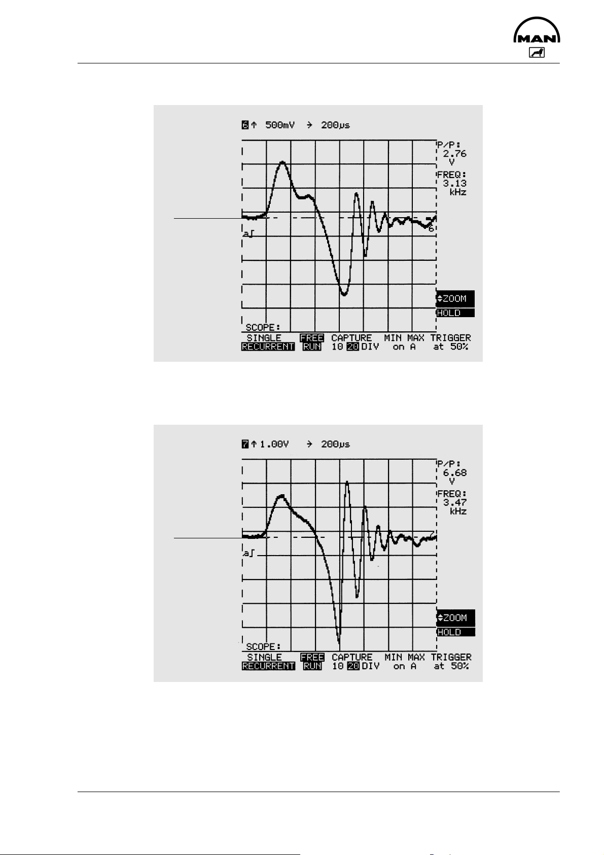
Voltage signal of the needle movement sensor at 600 rpm
Oscilloscope
setting:
AC range
0 V
The diagram above shows the qualitative curve of the NBF signal at an engine speed of 600 rpm.
Voltage signal of the needle movement sensor at 1200 rpm
Oscilloscope
setting:
AC range
0 V
45
Page 48

Testing
Resistance bank (control unit Pin 35)
Flash code: 1x long, 12x short
Fault indication: Fault is not indicated by the EDC indicator lamp
Fault path: Multistage switch for engine speed reduction
- Voltage to high
- Voltage to low
- Wrong voltage
Effect of fault: None with standard circuit
Function: Voltage signals are ascertained via the multistage input (control unit pin 35),
their values are determined by external resistor interrupters in the EDC control
box.
Possible cause: Line break, short-circuit, resistor bank defective, control unit defective
Test precondition: EDC control unit disconnected
Socked box connected
Test Measurement Corrective measures
Resistor bank Measure resistance at the socket box
across pin 35 and pin 13
Set-point value:
Torque limit inaktiv: 0,4-0,7 kΩ
Torque limit aktiv: 6,2-11,6 kΩ
The fault also occurs when the resistance
is 0 Ω or ∞ Ω
Check lines
- Check plug connections
- Replace EDC control box
46
Page 49

Testing
Control box
Flash code: 1x long, 13x short
Fault indication: Fault is not indicated by the EDC indicator lamp
Fault path: Operating unit defective
- Voltage values incorrect or implausible
Effect of fault: The idle position can no longer be activated.
If the fault was only temporary (e.g. operating unit activated several times) the
system will be ready for operation after switching the “ignition” off an on again.
Function: The operating unit is resistor-coded, i.e. the control unit recognizes each
switching state according to the voltage level supplied. Faults are detected
when incorrect values are output over a certain period of time; e.g. electrical
fault or multiple operation (incorrect operation) of the operating unit.
Possible cause: Line break, short-circuit, operating unit defective, incorrect operation
Test precondition: EDC control unit connected
socket box connected
ignition switched on
Test Measurement Corrective measures
Control box Measure voltage at the socket box across
pin 44 and pin 13
Switch through all settings of the operating unit and determine relevant voltage
value
Setpoints:
Not activated: 3.15-3.55 V
- Check lines
- Check plug connections
- Replace the control box
- If no fault found, replace control
unit as a check (disconnect the
control unit only when the current is switched off)
47
Page 50

Testing
Resistance bank (control unit Pin 54)
Flash code: 2x long, 7x short
Fault indication: Fault is not indicated by the EDC indicator lamp
Fault path: Multistage switch for engine speed reduction
- Voltage to high
- Voltage to low
- Wrong voltage
Effect of fault: None with standard circuit
Function: Voltage signals are ascertained via the multistage input (control unit pin 54),
their values are determined by external resistor interrupters in the EDC control
box.
Possible cause: Line break, short-circuit, resistor bank defective, control unit defective 9 (eg
cold soldering joint. In this case the fault “multi-stage switch for torque limitation” 1x long, 12x short is read out too)
Test precondition: EDC control unit disconnected
Socked box connected
Observe the vehicle-specific circuit diagrams.
Test Measurement Corrective measures
Resistor bank Measure resistance at the socket box
across pin 54 and pin 13
Set-point value:
0,4-0,7 kΩ
- Check lines
- Check plug connections
- Replace resistance bank
48
Page 51

Testing
CAN system (control unit)
Flash code: 1x long, 15x short
Fault indication: Fault is not indicated by the EDC indicator lamp
Fault path: Control unit faulty
Effect of fault: The data exchange has been interrupted. Some engine data (speed, tempera-
ture of water and charge air, boost pressure and fuel consumption) no longer
displayed.
Possible cause: Line break, short-circuit
Test Measurement Corrective measures
Control unit No further testing necessary - Replace control unit (only di-
sconnect control unit once the
current is switched off)
49
Page 52

Testing
Main relay
Flash code: 2x long, 5x short
Fault indication: Fault is not indicated by the EDC indicator lamp
Fault path: Main relay
Contact sticks or jams (does not open)
Effect of fault: Under certain conditions, this fault may not be detected
Function: The negative side of the relay coil is triggered by the EDC control unit via the
control unit output pin 46. The main relay switch-off is delayed after the ignition is switched off (run-on).
During the run-on phase, various processor functions are checked and any
faults stored in the fault memory.
Possible cause: Short to ground, main relay faulty
Test precondition: EDC control unit connected
Socked box connected
Test Measurement Corrective measures
Main relay Measure voltage at socket box between
pin 47 and pin 18
Set-point values:
0 V at “ignition” off
U-Batt at “ignition” on
Measure voltage at socket box between
pin 46 and pin 18
Set-point values:
U-Batt at “ignition” off
0 V at “ignition” on
Note:
Pin 46 must switch to U-Batt within 5 seconds of the ignition being switched off (processor runon).
- Check lines
- Check plug connections
- If line OK, replace main relay
50
Page 53

Testing
Atmospheric pressure sensor (in control unit)
Flash code: 2x long, 8x short
Fault indication: Fault is indicated by the EDC indicator lamp coming on continuously
Fault path: Atmospheric pressure sensor in control unit faulty
Effect of fault: The power reduction at high altitudes for the protection of the exhaust turbo-
charger is not activated
Possible cause: Control unit faulty
Test Measurement Corrective measures
Control unit If only this fault code is stored in the me-
mory, testing is not possible, as the sensor is located in the control unit.
If, however, a faulty boost pressure sensor is also detected, this should be chekked first in accordance with the boost
pressure sensor test (page 33).
- Replace control unit (only disconnect control unit once the
current is switched off)
51
Page 54

Testing
CAN system (TSC1-FM message)
Flash code: 2x long, 13x short
Fault indication: Fault is indicated by the EDC indicator lamp coming on continuously
Fault path: EDC - CAN communication is faulty
Effect of fault: Idle speed
Possible cause: Line break, error in vehicle management system, no CAN message from vehi-
cle control
Test precondition: EDC control unit and CAN computer disconnected
Socket box connected to EDC plug
Test Measurement Corrective measures
Resistance
Resistance measurement between pin 30
(CAN-L) on the socket box and a downstream computer
Set-point value: 0 Ω
Resistance measurement between pin 31
(CAN-H) on the socket box and a downstream computer
Set-point value: 0 Ω
- Check line
- Check plug connection
- Activate vehicle control
52
Page 55

Testing
Safety relay
Flash code: 3x long, 1x short
Fault indication: Fault is not indicated by the EDC indicator lamp
Fault path: Safety relay
Effect of fault: Engine is shut down
Engine will not start
Function: The safety relay performs an important safety function in its capacity as an
independent, higher-ranking (redundant) engine shut-off device
The safety relay is activated in certain emergency situations when the engine
can no longer be shut off by controlling fuel delivery to zero - e.g. when the
control rod has jammed.
The safety relay interrupts the positive power supply (pins 15 and 16) to the
quantity magnet.
Possible cause: Possible cause: Line break, short-circuit, safety relay defective, faulty activa-
tion from control unit (control unit defective)
Test precondition: Socked box connected
Test Measurement Corrective measures
Check
Safety relay
Power supply Switch on “ignition”
Coil resistance
Safety relay
Start engine and let it idle
Pull off bridge at pin 14 on test box
Engine must stop within approx. 3 seconds
Measure voltage at socket box across pin 14
(+) and pin 19 (-)
Set-point value: U-Batt
Switch off ”ignition”
Disconnect control unit
Measure resistance at socket box across
Pin 14 and Pin 19
Set-point value: 200-300 Ω
- Check line
- Check plug connection
- Replace safety relay
- Check line
- Check plug connection
- Replace safety relay
If no fault found:
- Replace control unit
- Check line
- Check plug connection
- Replace safety relay
53
Page 56

Testing
Complete EOL program
Control unit, EEPROM processor 1 fault
Flash code: 3x long, 2x short
Fault indication: Fault is not indicated by the EDC indicator lamp
Fault path: Processor 1 in control unit faulty (EEPROM 1)
Possible cause: Control unit faulty, EOL programming not completed (voltage supply interrup-
ted)
Effect of fault: Engine is shut off
Engine will not start
Test Measurement Corrective measures
Power supply
Control unit
No further testing necessary - Delete error; for this purpose
switch ignition off and on
again
- Complete EOL programming, clear fault codes
- Replace control unit (only disconnect control unit once
the current is switched off)
54
Page 57

Testing
Complete EOL program
Control unit, EEPROM processor 2 fault
Flash code: 3x long, 3x short
Fault indication: Fault is not indicated by the EDC indicator lamp
Fault path: Processor 2 in control unit faulty (EEPROM 2)
Possible cause: Control unit faulty, EOL programming not completed (voltage supply interrup-
ted)
Effect of fault: Engine is shut off
Engine will not start
Test Measurement Corrective measures
Power supply
Control unit
No further testing necessary - Delete error; for this purpose
switch ignition off and on
again
- Complete EOL programming, clear fault codes
- Replace control unit (only disconnect control unit once
the current is switched off)
55
Page 58

Testing
External stop
Flash code: 3x long, 4x short
Fault indication: Fault is not indicated by the EDC indicator lamp
Fault path: Extern idle switch (control unit pin 50)
Effect of fault: Request for idle-speed quantity
Function: This function was originally developed as an “anti-driveaway protection” for
buses when the doors are open.
Only mode = 1 is active, ie request for idle-speed quantity. No entry is made in
the fault memory. Only in the event of mode = 2, ie “engine stop” an entry is
made in the fault memory.
In data sets only mode = 1 is used as standard
Possible cause: “Engine stop” is requested (only mode = 2)
Test precondition: Socked box connected
Observe the vehicle-specific circuit diagrams.
Test Measurement Corrective measures
Idle switch Measure resistance at the socket box
across pin 54 and pin 13
Set-point value: ∞ Ω
- no fault
56
Page 59

Testing
Output stage error
Flash code: 3x long, 7x short
Fault indication: Fault is not indicated by the EDC indicator lamp
Fault path: Cables / actuators for the relevant function
Effect of fault: The relevant output stage in the control unit is not triggered. Function not avai-
lable
Possible cause: Control unit faulty (Hardware-error)
Note vehicle-specific circuit diagrams
Test Measurement Corrective measures
Output stage component
Depends on the component - Check lines
- Check plug connections
- Check the component
- Replace control unit (only disconnect control unit once
the current is switched off)
57
Page 60

Testing
Control unit (processor run-on)
Flash code: 3x long, 8x short
Fault indication: Fault is not indicated by the EDC indicator lamp
Fault path: Control unit
- Processor run-on did not take place
Effect of fault: No direct effect
Function: Every time the engine is turned off, run-on takes place automatically for the
purpose of checking the various processor functions
Possible cause: Control unit faulty, main relay faulty, battery voltage switched off before “igni-
tion” of
Test precondition: EDC control unit disconnected
Socked box connected
Test Measurement Corrective measures
Control unit Test same as for undervoltage (page 40) and
main relay (page 50)
Other possible causes:
- Engine was shut down via battery + (e.g. by disconnecting the battery or actuating the main fuse switch)
- Power supply fault (e.g. undervoltage, main relay faulty, loose contact)
- Switch ignition on and off
again, clear fault code
- Same as pages 40 and 50
- Replace control unit (only disconnect control unit once
the current is switched off)
58
Page 61

Testing
Control unit watchdog run-on fault
Flash code: 3x long, 9x short
Fault indication: Fault is not indicated by the EDC indicator lamp
Fault path: Control unit faulty (watchdog test)
Effect of fault: None
Test Measurement Corrective measures
Control unit No further testing necessary - Replace control unit (only di-
sconnect control unit once the
current is switched off)
Other possible causes:
- Engine was shut down via battery + (e.g. by disconnecting the battery or actuating the main fuse switch)
- Power supply fault (e.g. undervoltage, main relay K1 faulty, loose contact)
59
Page 62

Testing
Control rod position sensor - loose contact
Flash code: 3x long, 10x short
Fault indication: Fault is not indicated by the EDC indicator lamp
Fault path: Control rod position sensor
- Signal too high
- Signal too low
Effect of fault: None
Possible cause: Line break, short-circuit, too little capacitance reserve (see page 25), control
rod position sensor set incorrectly, injection pump faulty
Test precondition: EDC control unit disconnected
Socked box connected
Test Measurement Corrective measures
Instrument coil Measure resistance at socket box across
pin 11 and pin 9
Set-point value: 18-25 Ω
Reference coil Measure resistance at socket box across
pin 11 and pin 10
Set-point value: 18-25 Ω
Measure resistance at socket box across
pin 18 and pin 9
Set-point value: > 10 MΩ
Measure resistance at socket box between pin 18 and pin 10
Set-point value: > 10 MΩ
In addition to the possibility of an electrical
fault, the fault described here may also be
caused by incorrect setting of the control
rod position sensor
- Check lines
- Check plug connections
- If no fault found, repair injection
pump
- Remove injection pump
- Adjust control rod position
sensor
60
Page 63

Testing
EGR actuator (permanent deviation)
Flash code: 3x long, 11x short
Fault indication: Fault is not indicated by the EDC indicator lamp
Fault path: EGR actuator
Effect of fault: EGR function not available
Possible cause: Cable interrupted, short-circuit, check-back switch defective, mechanical de-
fect on actuator
Test precondition: Socket box connected
Note: In diagnosis mode the EGR actuator test can be activated via MAN-Cats. If
the fault memory is read out after the actuator test it always contains the fault
3B Hex. “EGR actuator, permanent deviation” (3x long, 11x short), even if the
fault was deleted before the actuator test.
Although it is unsatisfactory for service, this behaviour is unfortunately unavoidable and is correct for the coded software.
The fault memory must therefore be deleted without fail after the EGR actuator test.
Note vehicle-specific circuit diagrams
Test Measurement Corrective measures
Check-back switch
(reed contact)
Solenoid valve
triggering
Measure resistance at the socket box
across pin 15 and pin 24
Set-point value: >1 Ω
Measure resistance at the socket box
across pin 39 and pin 18
Set-point value: 39-47 Ω
- Check lines
- Check plug connections
- If no fault found, replace control
unit
- Check lines
- Check plug connections
- If no fault found, replace control
unit
61
Page 64

Testing
PBM interface
Flash code: None
Fault indication: Fault is not indicated by the EDC indicator lamp
Fault path: Control unit input pin 52
- Faulty
- Interrupted
Effect of fault: No PBM signal at pin 29 (steady voltage U-Batt)
Possible cause: Short to negative, line break
Test precondition: EDC control unit connected
Socked box connected
“Ignition” switched off
Test Measurement Corrective measures
Lines
Note:
Battery voltage must be applied at pin 52 against pin 18/19 with the “ignition” switched on.
Measure resistance at socket box across pin
52 and pin 19
Setpoint: ∞ Ω
Measure resistance at socket box across pin
29 and pin 19
Setpoint: ∞ Ω
- Check line
- Check plug connection
62
Page 65
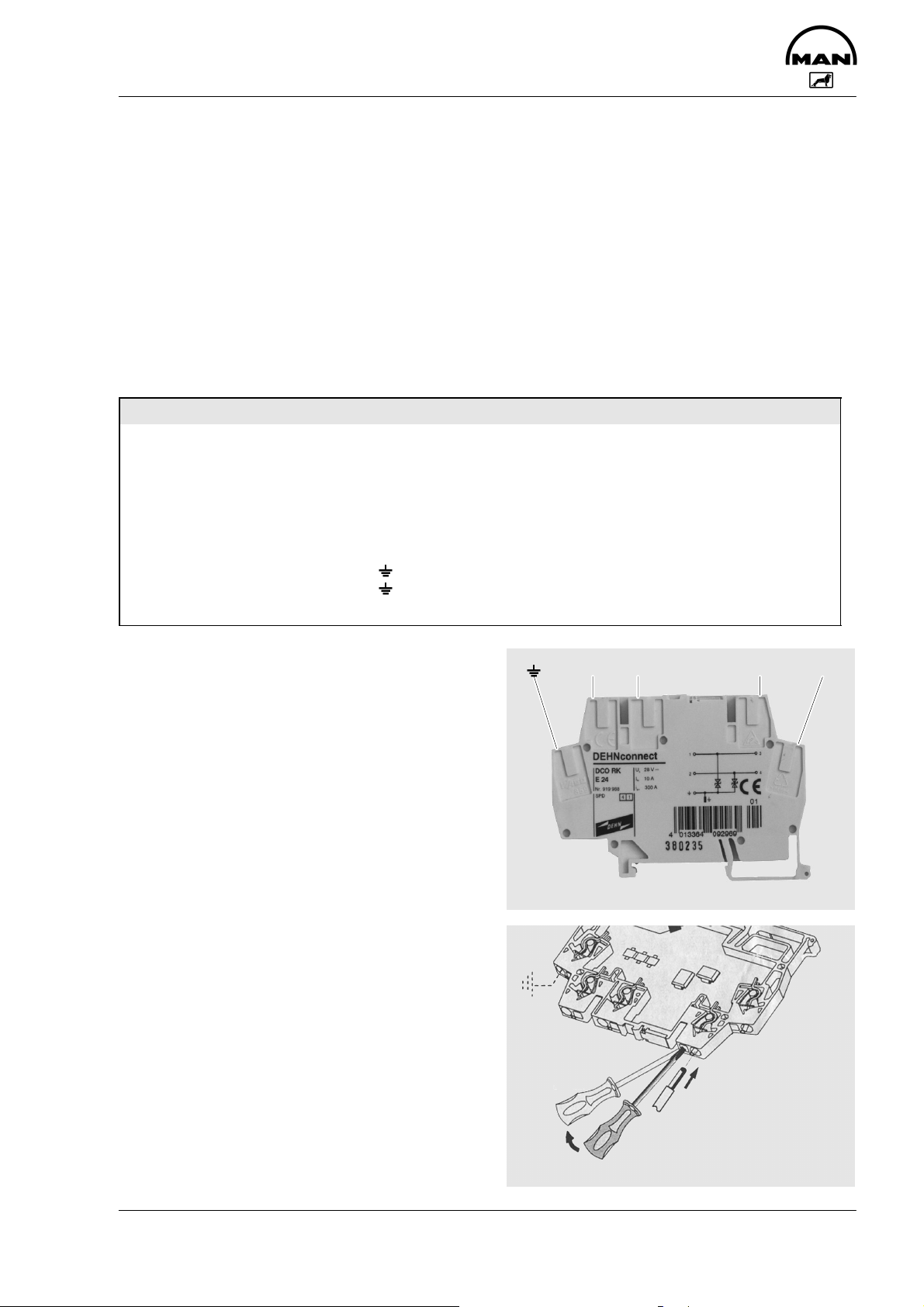
Testing
Overvoltage protection
Flash code: None
Fault indication: Fault is not indicated by the EDC indicator lamp
Fault path: Overvoltage protection
- Faulty
- Interrupted
Effect of fault: Engine will not start
Possible cause: Short circuit to negative terminal or to earth
Test precondition: EDC control unit disconnected
Socked box connected
“Ignition” switched off
Test Measurement Corrective measures
Lines Measure resistance at overvoltage protection
across contact 3 and contact 4
Setpoint: ∞ Ω
Contact
OUT3 and OUT4
OUT3 and
OUT4 and
Setpoint: >10 MΩ
Fig. 1
Overvoltage protection
IN1 IN2
- Replace overvoltage pro-
tection
OUT3
OUT4
Fig. 2
Installation instructions for lines
1
2
63
Page 66

Plug connections
Pin No. Abbreviation Description
1 MES O Activation for fuel-delivery actuator
- Output, fuel-delivery control circuit
-I
11 A temporarily, on average 4.5 A, against batt., pulsed f=variable, pulse-width modulated
max
2 MES O Activation for fuel-delivery actuator
- Output, fuel-delivery control circuit
3 VHS O Control-slide mechanism
4 VHS O Control-slide mechanism
5 MBR 1 Not used
6 LEB 1 Not used
7 ARS 1 EGR actuator
8 SHGB 1 Heavy load maximum speed limitation
9 RWG M Control rod position transducer measuring coil (RWG 2)
- Control rod position evaluator circuit
10 RWG R Control rod position transducer reference coil (RWG O)
- Control rod position evaluator circuit
11 RWG Y Control rod position transducer centre pick-off (RWG 1)
- Control rod position evaluator circuit
12 CAN O Not used
13 GND A Sensor ground
14 EAB 1 Electrical shut-down
- Output (switch)
-I
1 A, U
max
15 Bat + Batt.+ via main relay
- Input battery +
- I with engine stationary 0.9 A, idle speed 1.5 A, operation 4.5 A, temporarily 16 A
16 Bat + Batt.+ via main relay
- Input battery +
17 NBF 0, HZGO Needle movement sensor and auxiliary rpm sensor
- Reference ground
18 Bat - Battery negative
- Input battery -
- I same as batt.+ (terminals 15 and 16)
19 Bat - Battery negative
- Input battery -
20 DIA-B Diagnosis lamp
- Output (switch)
-I
1 A, U
max
21 DZG 1 RPM sensor signal
- Input, dynamic
- Alternating voltage UPP idle speed approx. 2 V, max. 80 V, f=number of cyl. XN sec.
22 HZG 1 Auxiliary rpm sensor signal
- Input, dynamic
- Alternating voltage UPP idle speed approx. 2 V, max. 80 V, f=number of cyl. XN sec.
23 ZDR-E1 Intermediate engine speed control 1
- Input, static
Batt.+
24 ARS-E EGR check-back switch
25 FMS-E Not used
26 KUP-E Not used
27 PWG 1 Pedal travel sensor signal
- Input, analog
- Direct voltage, U approx. 0.4 to 4 V
28 TDS-A Engine speed signal
- Output
-U
against batt. -, square-wave signal, f=number of cyl. X N sec.
batt.
29 MPS-A Multiplex signal
- Interfaces
against batt. -,
batt.
against batt. -,
batt.
-1
-1
-1
64
Page 67

Plug connections
DescriptionAbbreviationPin No.
30 CAN-L Controller Area Network
- Interfaces
31 CAN-H Controller Area Network
- Interfaces
32 NBF 1 Needle movement sensor
- Input, dynamic
approx. 2 V
-U
PP
33 LDF 2 - boost pressure sensor
- Output, supply
- Controlled direct voltage, U approx. 5 V
34 KTF 1 Fuel temperature sensor
- Input, analog
35 MDB 1 Multi-stage input (torque limitation)
- Input, analog
- Input by change in resistance
36 LDF 1 Boost pressure sensor signal
- Input, analog
37 FGB 1 Not used
38 EOL E Not used
39 LGS-E Idle speed switch signal
- Input, static
- against GND-O (terminal 13)
40 MST-E External engine cut-out
41 ZDR-E2 Intermediate engine speed control 2
- Input, static
Batt.+
42 MBR-E Not used
43 BRE-E Not used
44 FGR 1 Speed control device
45 PWG 2 Pedal travel sensor
- Output, supply
- Controlled direct voltage, U approx. 5 V
46 HRL O Main relay
- Output (switch)
-I
0.3 A, batt. - against batt.+
max
47 K15-E Terminal 15, digit. Data for control unit
- Input, static
Batt.+
48 ISO-K ISO-K link to ISO protocol
- Interfaces
49 ISO-L ISO-L link to ISO protocol
- Interfaces
50 TKS-E Door contact switch
- Input, static
Batt.+
51 FGG 1 Driving speed sensor signal
- Input, dynamic
- Square-wave voltage UPP 8.5 V, f. variable
52 PBM-E Pulse-width modulated input signal 1
- Interface
53 WTF 1 Coolant temperature sensor
- Input, analog
54 HGB 1 Multi-stage input, maximum speed limitation
- Input, analog
- Input by change in resistance
55 LTF 1 Charge-air temperature sensor
65
Page 68

EDC diagnostic tools
Bosch socket box Y261 A30 186
Fig. 1
Connection between control unit and EDC cable
harness in terminal box for testing EDC
Arrow: Control unit plug
MAN-Cats interface 93.09000-6015
(Connection between adapter cable and note
book)
Fig. 2
1
1
À Connector for note book
Á Connector for MAN-Cats interface in terminal
box
Notebook computer
minimum equipment:
Fig. 3
S 386 processor
S 4 MB RAM
S RS 232 Com 1 interface
S MS-DOS 5.0 or higher
2
2
3
66
Page 69

MAN-Cats Diagnostics System
MAN CATS is a diagnostics system for the engine electronics which operates with the aid of a laptop computer.
The features the following functions:
1. Reading EDC errors in text format
2 Clearing the fault memory
3. Monitoring the following operational parameters:
S Boost pressure
S Control rod position
S Engine speed
S Coolant temperature
S Charge air temperature
S Fuel temperature
S Pedal travel sensor position, i.e. throttle lever position
S Battery voltage
S Additional EDC parameters
S Needle movement sensor
However, the monitoring data cannot be stored or printed.
The following equipment is necessary to work with the laptop:
S Interface, white
MAN Item no. 93.09000-6015
S MAN-Cats software
Operating system disk D1
MAN Item no. 81.99298-8130 German
81.99298-8071 French
81.99298-8082 English
81.99298-8033 Spanish
81.99298-8014 Italian
S Diagnostic software
EDC Bosch MS 5, Disk D 12
MAN ltem no. 81.99298-8300 German
81.99298-8231 French
81.99298-8222 English
81.99298-8193 Spanish
81.99298-8134 Italian
67
Page 70

MAN-Cats Diagnostics System
Caution:
An existing laptop should meet the following minimum criteria for EDC:
S 386 processor
S 4 MB RAM
S 9-pin serial port
The MAN Cats software may only be run on MS DOS 5.0 or higher.
The following PC is required for the MMDS diagnostics system
Laptop with the following specification
Suitable for the MMDS diagnostics system for MAN marine engines:
S 266 MHz processor
S 32 MB RAM
S Min. 1,0 GByte hard drive
S CD-ROM drive
S Floppy disk drive
S Lithium battery charger (without memory effect)
S Trackball
S Serial interface, cable-based
S TFT display, 800 x 600 resolution (pixels width x height), min. 256 colours
68
Page 71

MAN-Cats - Software Description
The software can be installed under DOS (version 5) or Windows.
Installation under Windows 95, 98, NT, WIN 2000:
Create a folder named “MAN-Cats” on hard disc C:.
Copy the contents of the floppy disk labelled “D1” from the floppy disk drive to a new folder on the hard
disk.
Run “Install.exe” from the hard disk.
When requested, select installation of the D12 diagnostics software and at the same time deselect D43.
When requested to do so, insert the next D12 disk and continue.
In DOS, the software is run by entering “C:man_cats diagnose”.
The following will appear on the screen:
Use the arrow keys to highlight “Diagnostics”, then press “Enter”.
69
Page 72

MAN-Cats - Software Description
The following will appear on the screen:
Using the arrow keys, select “Mot” engine control.
The following will appear on the screen:
Using the arrow keys, select “EDC Bosch MS5/M(S)5”.
70
Page 73

MAN-Cats - Software Description
The following screens will appear:
71
Page 74

MAN-Cats - Software Description
72
Page 75

MAN-Cats - Software Description
EDC is being
scanned
73
Page 76

MAN-Cats - Software Description
After this stage, the contents of the fault memory are shown first (see screenshot below).
Fault description:
↑ : too great ¢ measured value too high
↓ : too small ¢ measured value too low
- : no signal ¢ possible line break, sensor faulty
? : implausible ¢ unknown fault
J : saved ¢ fault has been stored
n : present ¢ fault exists at present
~ : sporadic ¢ momentary fault
Frequency: Depending on the channel, the EDC counts the faults from 1 to 40 or 1 to 210. If the fault is no
longer present when ignition is switched back on again, the frequency of the fault is reduced
by 1. (Our example therefore shows 3 faults which were present at least once).
Peripheral conditions: shows other important channels as additional information, e.g. the engine speed at
which the fault occurred and the magnitude of the fault.
Once the fault memory has been examined and noted, press “Enter” to go the submenu where you select
the “Bus” function.
74
Page 77

MAN-Cats - Software Description
75
Page 78

MAN-Cats - Software Description
Guided by the menu, you now come to the “Instructions / Questions” dialogue box.
Depending on the version of the software, here you will find various submenus which are explained in detail
on the following pages.
76
Page 79

MAN-Cats - Software Description
In the “Control unit identification” submenu, you will find, for example, the engine number, which must be
checked. If the wrong control unit has been assigned to the wrong engine, it is essential that you inform
MAN. For further details, see the screenshot below.
The next submenu, “Fault memory contents” once again shows the current fault memory of the EDC (see
screenshot below as an example).
The “Actuator test” submenu item contains an “EHAB” test and will not be dealt with in greater detail here.
77
Page 80
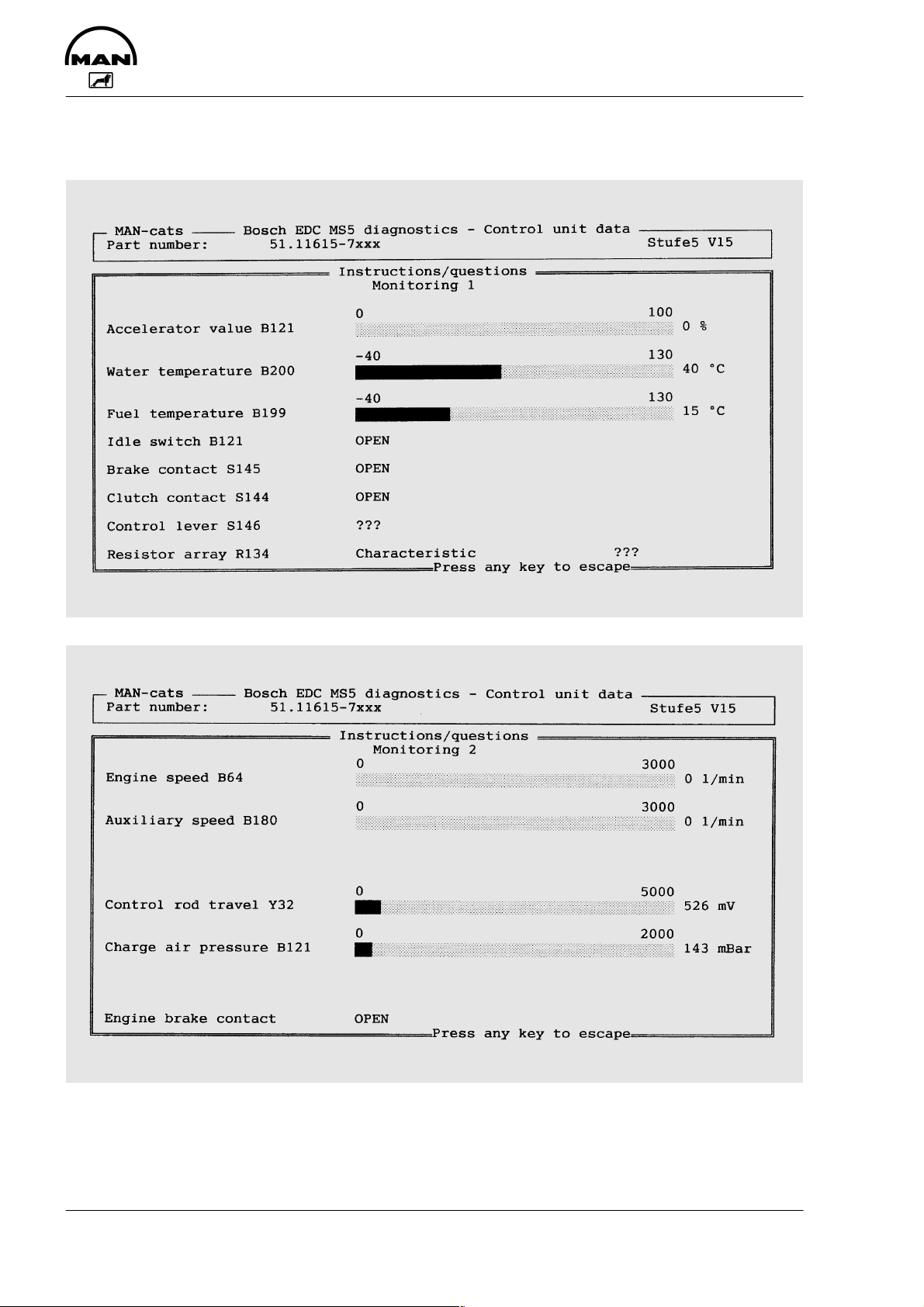
MAN-Cats - Software Description
“Monitoring 1-3” shows various engine parameters, see the following screenshots. The measured data
cannot be stored.
78
Page 81

MAN-Cats - Software Description
Depending on the software version, there is also a “Monitoring X” or “Definition monitoring X” submenu.
In Definition Monitoring X, up to 6 freely selectable measuring channels can be selected by pressing “Enter”
(see screenshot below).
79
Page 82

MAN-Cats - Software Description
When you have finished selecting the measuring channels, select “Complete definition of monitor window”.
After this, you can view the selected measuring channels in “Monitoring X” (see screenshot below).
80
Page 83

MAN-Cats - Software Description
After diagnosing or measuring the engine parameters, select “End”. The following window will appear.
Once you have left the “Instructions / Questions” main menu by pressing “Enter”, the following will appear
on the screen (see screenshot below).
81
Page 84

MAN-Cats - Software Description
Confirm with “Yes”. You will then be guided through the menu, using “Enter” to confirm (see ...)
82
Page 85

MAN-Cats - Software Description
Following the instructions above will return you to the beginning of the program.
You can now quit the “MAN_CATS” software by selecting “Exit”.
83
Page 86

Notes
.............................................................................................................................................
.............................................................................................................................................
.............................................................................................................................................
.............................................................................................................................................
.............................................................................................................................................
.............................................................................................................................................
.............................................................................................................................................
.............................................................................................................................................
.............................................................................................................................................
.............................................................................................................................................
.............................................................................................................................................
.............................................................................................................................................
.............................................................................................................................................
.............................................................................................................................................
.............................................................................................................................................
.............................................................................................................................................
.............................................................................................................................................
.............................................................................................................................................
.............................................................................................................................................
.............................................................................................................................................
.............................................................................................................................................
.............................................................................................................................................
.............................................................................................................................................
.............................................................................................................................................
.............................................................................................................................................
.............................................................................................................................................
84
Page 87

Rating data sheet
85
Page 88

Notes
.............................................................................................................................................
.............................................................................................................................................
.............................................................................................................................................
.............................................................................................................................................
.............................................................................................................................................
.............................................................................................................................................
.............................................................................................................................................
.............................................................................................................................................
.............................................................................................................................................
.............................................................................................................................................
.............................................................................................................................................
.............................................................................................................................................
.............................................................................................................................................
.............................................................................................................................................
.............................................................................................................................................
.............................................................................................................................................
.............................................................................................................................................
.............................................................................................................................................
.............................................................................................................................................
.............................................................................................................................................
.............................................................................................................................................
.............................................................................................................................................
.............................................................................................................................................
.............................................................................................................................................
.............................................................................................................................................
.............................................................................................................................................
86
Page 89

Rating data sheet
1. Revision list
Date Revisions
30.05.1994 First issue
26.04.1999 New edition
2. Scope This data sheet comprises the specifications and tests for the electronic control unit EDC-MS5 requi-
red to guarantee the functions listed in the following under the specified ambient conditions.
3. General features
3.1 Place of installation Frame (chassis)
3.2 Electrical connection 55-pin plug connection
3.3 Weight approx. 1.4 kg
3.4 Degree of protection
Protection against shock-hazard and foreign
bodies in accordance with DIN 40 050, Part 9; IP 54 A
Protection against water ingress with connector
plugged in in accordance with DIN 40 050, Part 9; IP 54 A
without protecting sleeve in accordance with DIN 40 050, Part 9; IP 30
87
Page 90

Rating data sheet
4. Temperature range Ta: Temperature of mounting surface
Tu: Temperature of ambient air
4.1 Storage temperature
Permanent, not installed -40°C ... +85°C
Temporary, max. 1h in installed position -40°C ... +100°C
4.2 Operating temperature
Still air
Ambient temperature Tu, permanent -40°C ... +65°C
Mounting surface Ta, permanent -40°C ... +65°C
Moving air
Ambient temperature Tu, permanent -40°C ... +70°C
Mounting surface Ta, permanent -40°C ... +70°C
Tu =Ta, temporary -40°C ... -85°C
See diagram:
Tu= Ta
85°C
70°C
*
*
-
0 5 t [min.]
Control unit switched off Control unit switched on
88
Page 91

Rating data sheet
5. Mechanical characteristics
5.1 Vibration stress
5.1.1 Sinusoidal vibration test in accordance with DIN 40046 Part 8 ,Fc (IEC 68-2-6)
Max. acceleration amplitude 50 m/s
Frequency range 10 Hz ... 200 Hz
Frequency change rate 1 okt./min.
Test duration 24 h per main coordinate
5.1.2 Broadband noise test in accordance with DIN 40046 Part 22, Fd (IEC 68-2-34)
Total acceleration (effective value) 45 m/s
Frequency range: 10 Hz ... 1000 Hz
Test duration 24 h per main coordinate
5.2 Shock stress, test in accordance with DIN 40046 Part 7, (IEC 68-2-27)
Max. acceleration amplitude 1000 m/s
2
2
2
Shock form Semi-sinusoidal
Duration of nominal shock 6 ms
Test duration 3 shocks per main coordinate in both directions
(18 shocks)
The frequency and acceleration value specified in 5.1 and 5.2 apply to the vibration testing table.
89
Page 92

Rating data sheet
6. Electrical ratings
6.1 Supply voltage range
6.1.1 Rated voltage 24 V
6.1.2 Permissible supply voltage 7.0 ... 32 V normal operation
(measured at the batt.+, batt.- min. 16 V for 50 ms after switching on terminals
of the control unit) the control unit
The definition provided in Section 7 applies to the voltages U-batt+ ≤ 7 V or U-bat- ≥ 32 V.
6.1.3 Residual ripple of supply voltage (Operation without battery not permitted)
Effective value of supply voltage: U-batt eff = 500 mV max.
(Measured at the batt+, batt- terminals of the control unit with the control unit switched on and the
engine running. The value need not be maintained during the start procedure)
6.2 Power loss, control unit
(idle speed, engine at operating temperature) approx. 18 W
6.3 Polarity reversal protection By coded control unit connector,
polarity reversal of battery does not
result in destruction of control unit
when the main relay is activated by
the control unit.
6.4 Short-circuit strength
- Conditions: Max. 1 short-circuit simultaneously For all plug connections against batt+, batt-
- Ta and Tu≤65°C, and against one another except for BAT+, BAT-,
- U-Batt ≤28V GND 0. NBF 0. CAN H and L
- control unit is powered with U-batt
Restricted:
RWGR. RWGM. RWGY short-circuit at
max. 26 V permissible for max. duration of 1 min.
6.5 Heat radiation max. 20 W
90
Page 93

Rating data sheet
7. Immunity to interference Pulses in accordance with ISO 7637-2 are permitted on the batt+/batt- line if they are within the fol-
lowing rated values.
The control unit can switch off as a precautionary measure in the case of supply voltages outside the
range 7V ≤ U-Bat+ ≤ 32V.
The function is resumed on returning to the permissible voltage range.
7.1 ISO pulses 1 to 4
Test pulse Vs [Volt] Ri [Ohm] tl [s] Number of pul-
1a -200 10 5 5 000 -
2 +100 10 0,5 5 000 -
3a -200 50 100µ - 1
3b +200 50 100µ - 1
7.2 ISO pulse 5 (load dump)
Vs = 57 V Ri = 2 Ω td = 200ms (at +U-Batt = 28V)
Set-up temperature Ta ≤ 65°C
Ambient air Tu ≤ 65°C
Minimum wait time between subsequent pulses 1 min
Number of pulses 10
Voltage limitation by the internal load dump feature cuts in at min. 34 V.
7.3 EMV
7.3.1 Irradiation immunity
Frequency range 1 MHz ... 1000 MHz
(measure up to 400 MHz)
Test duration [h]
ses
Field strength 100 V/m sinusoidal, non-modulated
(stripline measurement)
Criterion Engine overrevving or shutting down
not permitted.
Accuracy deviation permissible.
7.4 Interference suppression In accordance with VDE 0879 Part 3, interference
suppression level 2.
91
Page 94

Rating data sheet
8. Resistance to motor vehicle-specific liquids / fluids The control unit is resistant to diesel fuel, petrol, engine oil, engine cleaner, brake fluid, battery acid,
windscreen washer fluid, isooctane / toluene
9. Mechanical test data
9.1 Vibration stress As Point 5.1
9.2 Shock stress As Point 5.2
9.3 Alternating temperature Test Nb in accordance with DIN 2 Part 14 Clause
3 (IEC 68-2-14 Nb)
Lower test temperature -40°C
Upper test temperature +85°C
Number of cycles 100
Temperature change rate < 10K/min
Holding time at upper stress temperature 15 minutes each
9.4 Moisture resistance
9.4.1 Test in accordance with DIN standard Test Db in accordance with FW 2 DIN 30 (IEC
68-2-30)
Number of cycles 28
Function test after 7 cycles
9.4.2 Active moisture-alternating temperature test
Rel. humidity 95%
Normal temperature phase at 40°C
Duration 240 h
Low temperature phase at -10°C
Duration 2 h
Changeover time < 3 min
10. Service life test
The service life test comprises a mechanical test in accordance with Points 5.1 and 5.2 as well as a
climatic test in accordance with Points 9.3 and 9.4. Function measurements in accordance with the
test and adjustment specifications are conducted after the individual tests.
92
Page 95
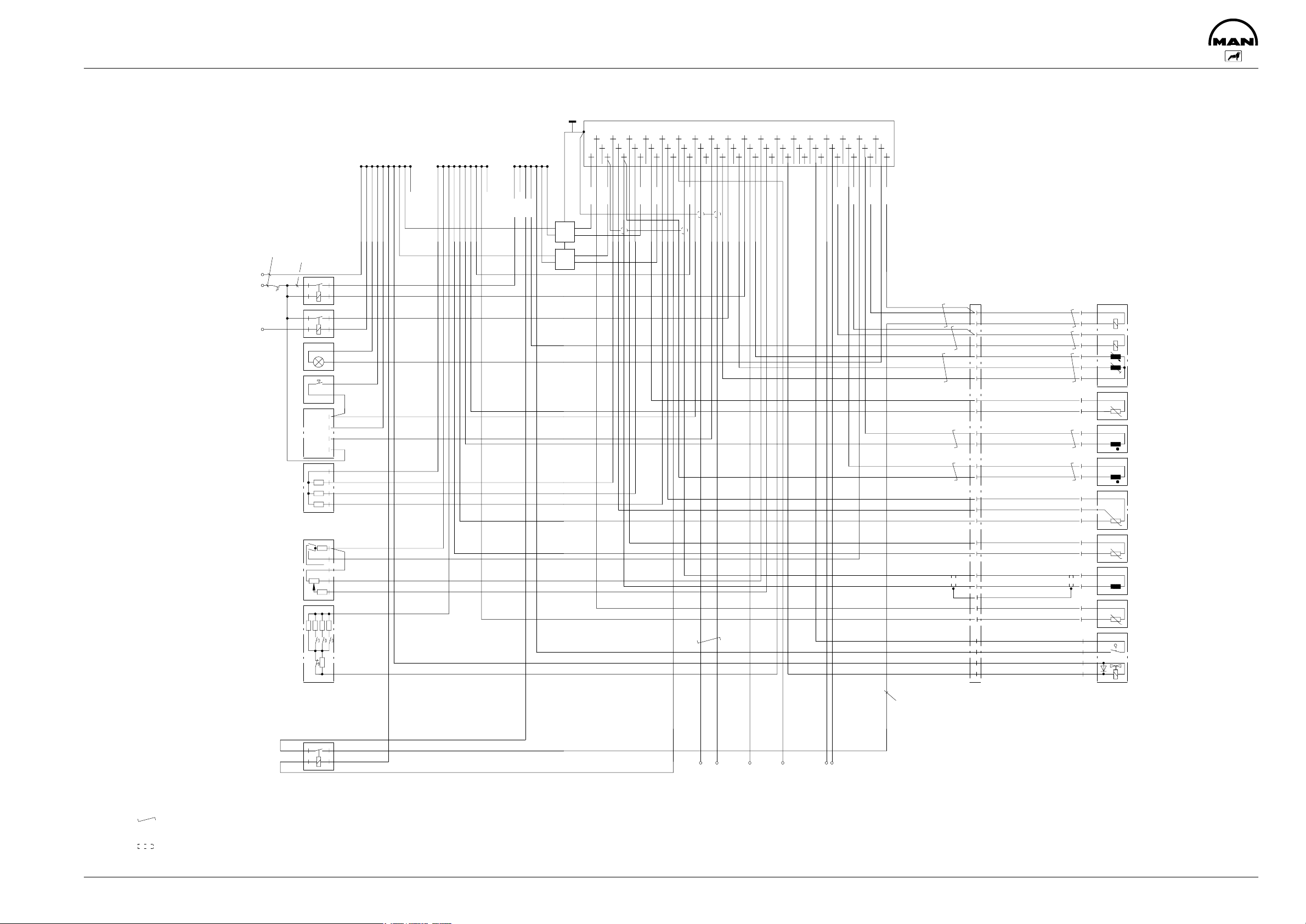
EDC-Connection diagram
HRL 0
RWG R
K15 E
CAN L
ISO K
CAN H
ISO L
GND 0
NBF 1
LDF 2
FGG 1
MDB 1
WTF 1
LFD 1
HGB 1
BAT -
LTF 1
BAT -
NBF 0
BAT +
BAT +
KTF 1
TKS E
EAB 1
RWG Y
TDS A
PWG 2
PWG 1
RWG M
FGR 1
ARS 1
ARS E
ZDR E2
VHS 0
ZDR E1
VHS 0
HZG 1
MES 0
DZG 1
MES 0
DIA B
Batterie
battery
Hauptrelais K170
main relay
Einschalt- Relais K264
switch on relay
Diagnoselampe
1,2 - 2W
diagnosis lamp
Taster
Blinkcodeanforderung
key for
flash code request
Diagnosesteckdose X200
MAN - Cat
diagnosis socket
Widerstandsgruppe R134
resistance group
-
+
Kl.15
15A
Sensor -
Batterie -
battery
19
18
2
6
2,5
2
18/19
87
30
15/16
46
85
86
87
30
47
18/19
86
85
18/19
20
18/19
49
49
Z
18/19
A
48
a
15/16
+
D
13
5
54
2
511
35
8
511
51
6
3K
sensor
13
2
2,5
Batterie +
battery
15
16
2
2
EMV-Stoerschutz 51.25902-0079
2,5
EMV-protector 51.25902-0079
2,5
1
2
1
2
55
37
19
18
2
2
2,5
2,5
3
4
3
4
52
54
53
51
50
36
35
34
16
17
2
2,5
32
33
15
13
14
2
2
2,5
2,5
47
49
31
12
46
48
30
11
45
43
42
40
39
29
10
44
28
27
26
9
8
7
41
24
23
25
5
6
4
2
2,5
38
22
21
20
EDC-
2
3
2
2
2,5
2,5
Steuergeraet
1
control unit
2
2,5
K324/87 (15/16)
1
2
3
4
15/16
9
10
11
34
13
21
13
22
17
33
36
13
X337
A
C
E
G
f
m
r
g
H
e
F
N
P
n
h
J
ws
sw
ws
sw
br
sw
bl
ws-sw
vio-ws
ws
sw
rt
sw
vio
ge
ws-sw
2,5
2,5
2,5
2,5
2
2
2
7
2
4
2
3
5
1
6
3
1
2
1
1
2
2
1
1
2
2
3
1
4
3
2
Stellwerk
fuel control rack
Hubschieber
control slide
Regelweggeber
control rod travel transmitter
Kraftstofftemperaturfuehler
fuel temperature sensor
Drehzahlgeber
speed transmitter
Hilfsdrehzahlgeber
auxiliary speed transmitter
Ladedruckfuehler
charge air sensor
Pedalwertgeber B127
accelerator pedal position sensor
Drehzahlbedienteil S157
speed control element
Relais K324
Redundante Abstellung
relay for redundant shutdown
Verdrillte Leitungen
=
min 20/m
twisted cables
= abgeschirmte Leitung MAN-Nr. 07.08233-7582
shielded cable
15/16
s
t
v
u
w
l
k
d
b
a
c
Motorstecker
engine plug
2,5
53
13
32
17
55
13
24
15/16
18/19
7
2
3
13
1K
6
39
5
13
4
45
1K
2
27
1K
13
62
680
680
200
Sp-
+
1K
Aus
44
87
863085
X337/C
18/19
Allgemeiner EDC-Schaltplan MS5.5
EDC MS5.5, general wiring diagram
Fahrzeugspezifische Schaltplaene beachten!
Note vehicle specific wiring diagrams!
31
CAN 1
30
CAN 2
28
50
Signal Motordrehzahl
signal engine speed
15/16 (BAT+)
Motorstop extern
engine stop extern
13 (GND 0)
41
23
15/16 (BAT+)
15/16 (BAT+)
Zwischendrehzahl 1
Zwischendrehzahl 2
intermediate speed
intermediate speed
14
bl
grue
ws-rs
ws-br
sw
gr
gr-sw
sw-ws
sw
bl
rt-sw
3
1
1
2
2
1
1
3
1
4
3
2
4
1
3
2
Kuehlmitteltemperaturfuehler
coolant temperature sensor
Nadelbewegungsfuehler
needle movement sensor
Ladelufttemperaturfuehler
B123 B198 B124 B125 B200 B199 B197 Y130
charge air temperature sensor
AGR-Zylinder
Y280
Am Motor
at engine
8112
93
Page 96

Page 97

Electronic Diesel Control
Description of inputs and outputs
95
Page 98

1. Key to definitions
C
: EMC capacitor
EMC
f: Frequency
F
: Absolute error
abs
Io: Output current
KS: Short-circuit
LL: Idle speed
Rpu: Pull-up resistor
Rq: Shunt
Rpd: Pull-down resistor
Rin: Input resistance
R
: Internal alternator resistance
Gen
Sn: Threshold correction
tr: Rise time
tf: Fall time
t0: Dead time for detecting signal 0
passage
from high to low between connector pin and processor
t: Time constant
tAL: Charge time constant
tEL: Discharge time constant
Uo: Output voltage
UL: Switching threshold for logical
LOW
UH: Switching threshold for logical
HIGH
U
: Hysteresis
Hys
UGr: Basic threshold
ULL: Idle speed voltage
UR: Reference voltage of ADC,
UR=5V ± 4%
Uin: Input voltage
U
: Minimum or maximum permiss-
inz
ible input voltage
U
: Cutout threshold
off
U
: Short-circuit at output set to
oLK
logical LOW
U
: Short-circuit at output set to
oHK
logical HIGH
96
Page 99

2. General information
The control unit must be connected in accordance with circuit diagram 51.17099-8087 together with the
assemblies belonging to the system.
If not otherwise specified, all inputs and outputs are short-circuit-proof to ground and +U
≤ 28 V, TU ≤
batt
65°C.
Operation without the battery is not permitted.
The control unit may be damaged as the result of the increased power loss in the event of a short-circuit in
more than two plug connections against on another or against the supply voltage.
Supply voltages and ground connections are not short-circuit-proof and are not protected against polarity
reversal.
If not otherwise specified, all values apply in the temperature and voltage range as specified by TKU.
Control unit supply:
BATT+ across pin 15, 16 (connected internally, must be connected externally)
BATT- across pin 18, 19 (connected internally, must be connected externally)
The time constant values t apply at an internal alternator resistance of 0W.
The current directions are defined in accordance with the load count system:
Positive currents flow into the control unit.
Negative currents flow out of the control unit.
If not otherwise specified, the working range for analog inputs is from 0 .. UR.
Data acquisition accuracy is always referred to U
Rnominal
=5.000V
97
Page 100

3. Description of inputs and outputs
3.1Analog inputs
Plug connection: 27 Function group: Analog input
Connector designation: PWG 1 Reference ground: GND 0 (13)
Description of input
Characteristic
Conditions Dim. Min. Typ. Max.
parameter
EMC capacitor C
Input resistance R
Idle speed voltage U
EMC
in
LL
Input filter t R
U
in
=0W m
Gen
nF 1.2 1.5 2.2
kW 97 100 103
V GND 0
s
0.9 1.5 2.1
Input voltage
Evaluation range U
Data acquisition accu-
inz
F
abs
Uin is in range of U
inz
V 0.1 UR-0.1
% ±2
racy DUin from input pin
up to number of processors
Remarks:
- The data acquisition accuracy is based on radiometric signal processing with sensor supply PEG 2.
Plug connection: 45 Function group: Sensor supply,
short-circuit-proof
Connector designation: PWG 2
Characteristic para-
Conditions Dim. Min. Typ. Max.
meter
EMC capacitor C
Output voltage U
Output short-circuit
EMC
o
Io≤-10 mA V UR-0.01 UR=5V UR+0.01
[Ik] Uo=0V mA 10 25
current
Remarks:
Description of output
nF 1.2 1.5 2.2
98
 Loading...