

Page 1
Page 2

Page 3

Foreword
Dear Customer
These instructions are intended to help you properly carry out repairs on the electronically controlled diesel
injection system described in this document.
In writing these instructions, we have assumed that you have the necessary knowledge of control systems
for working on and with the electronic diesel control.
Best regards
MAN Nutzfahrzeuge Aktiengesellschaft
Nuremberg Plant
Since our products are in continuous development, we reserve the right to make technical modifications.
2002 MAN Nutzfahrzeuge Aktiengesellschaft
Reprint, duplication or translation, as a whole or in part without the written approval of MAN is prohibited.
MAN reserves all rights accorded by the relevant laws on copyright.
MTDA Technical status: 02.2002 51.99598–8049
1
Page 4

Contents
Safety information 4 . . . . . . . . . . . . . . . . . . . . . . . . . . . . . . . . . . . . . . . . . . . . . . . . . . . . . . . . . . . . . . . . . . . . . . . .
Electronic diesel control 6 . . . . . . . . . . . . . . . . . . . . . . . . . . . . . . . . . . . . . . . . . . . . . . . . . . . . . . . . . . . . . . . . . . .
System description 7 . . . . . . . . . . . . . . . . . . . . . . . . . . . . . . . . . . . . . . . . . . . . . . . . . . . . . . . . . . . . . . . . . . . . . . .
Component description 9 . . . . . . . . . . . . . . . . . . . . . . . . . . . . . . . . . . . . . . . . . . . . . . . . . . . . . . . . . . . . . . . . . . . .
Control unit plug connector 9 . . . . . . . . . . . . . . . . . . . . . . . . . . . . . . . . . . . . . . . . . . . . . . . . . . . . . . . . . . . . .
Injection pump 11 . . . . . . . . . . . . . . . . . . . . . . . . . . . . . . . . . . . . . . . . . . . . . . . . . . . . . . . . . . . . . . . . . . . . . . . .
Electromagnetic fuel-delivery regulator 11 . . . . . . . . . . . . . . . . . . . . . . . . . . . . . . . . . . . . . . . . . . . . . . . . . . .
Resistor bank 12 . . . . . . . . . . . . . . . . . . . . . . . . . . . . . . . . . . . . . . . . . . . . . . . . . . . . . . . . . . . . . . . . . . . . . . . . .
Electrohydraulic shut-off device EHAB 13 . . . . . . . . . . . . . . . . . . . . . . . . . . . . . . . . . . . . . . . . . . . . . . . . . . . .
Drive stage selection 16 . . . . . . . . . . . . . . . . . . . . . . . . . . . . . . . . . . . . . . . . . . . . . . . . . . . . . . . . . . . . . . . . . . .
Turbo air and coolant temperature sensors 17 . . . . . . . . . . . . . . . . . . . . . . . . . . . . . . . . . . . . . . . . . . . . . . . .
Turbo pressure sensor (51.27421–0181) 18 . . . . . . . . . . . . . . . . . . . . . . . . . . . . . . . . . . . . . . . . . . . . . . . . . .
RPM sensor 19 . . . . . . . . . . . . . . . . . . . . . . . . . . . . . . . . . . . . . . . . . . . . . . . . . . . . . . . . . . . . . . . . . . . . . . . . . .
Notes on operation 20 . . . . . . . . . . . . . . . . . . . . . . . . . . . . . . . . . . . . . . . . . . . . . . . . . . . . . . . . . . . . . . . . . . . . . . .
Self-diagnosis 21 . . . . . . . . . . . . . . . . . . . . . . . . . . . . . . . . . . . . . . . . . . . . . . . . . . . . . . . . . . . . . . . . . . . . . . . . . . . .
Flash code 22 . . . . . . . . . . . . . . . . . . . . . . . . . . . . . . . . . . . . . . . . . . . . . . . . . . . . . . . . . . . . . . . . . . . . . . . . . . .
List of checking procedures 24 . . . . . . . . . . . . . . . . . . . . . . . . . . . . . . . . . . . . . . . . . . . . . . . . . . . . . . . . . . . . . . . .
Troubleshooting chart 27 . . . . . . . . . . . . . . . . . . . . . . . . . . . . . . . . . . . . . . . . . . . . . . . . . . . . . . . . . . . . . . . . . . . . .
Troubleshooting program 30 . . . . . . . . . . . . . . . . . . . . . . . . . . . . . . . . . . . . . . . . . . . . . . . . . . . . . . . . . . . . . . . . . .
Test 31 . . . . . . . . . . . . . . . . . . . . . . . . . . . . . . . . . . . . . . . . . . . . . . . . . . . . . . . . . . . . . . . . . . . . . . . . . . . . . . . . . . . .
Drive stage selection 31 . . . . . . . . . . . . . . . . . . . . . . . . . . . . . . . . . . . . . . . . . . . . . . . . . . . . . . . . . . . . . . . . . . .
RPM sensor 32 . . . . . . . . . . . . . . . . . . . . . . . . . . . . . . . . . . . . . . . . . . . . . . . . . . . . . . . . . . . . . . . . . . . . . . . . . .
Boost pressure sensor 33 . . . . . . . . . . . . . . . . . . . . . . . . . . . . . . . . . . . . . . . . . . . . . . . . . . . . . . . . . . . . . . . . .
Control rod position sensor 34 . . . . . . . . . . . . . . . . . . . . . . . . . . . . . . . . . . . . . . . . . . . . . . . . . . . . . . . . . . . . .
Coolant temperature sensor 35 . . . . . . . . . . . . . . . . . . . . . . . . . . . . . . . . . . . . . . . . . . . . . . . . . . . . . . . . . . . . .
Resistor bank 36 . . . . . . . . . . . . . . . . . . . . . . . . . . . . . . . . . . . . . . . . . . . . . . . . . . . . . . . . . . . . . . . . . . . . . . . . .
Fuel volume regulator 37 . . . . . . . . . . . . . . . . . . . . . . . . . . . . . . . . . . . . . . . . . . . . . . . . . . . . . . . . . . . . . . . . . .
Auxiliary rpm sensor 38 . . . . . . . . . . . . . . . . . . . . . . . . . . . . . . . . . . . . . . . . . . . . . . . . . . . . . . . . . . . . . . . . . . .
Charge-air temperature sensor 39 . . . . . . . . . . . . . . . . . . . . . . . . . . . . . . . . . . . . . . . . . . . . . . . . . . . . . . . . . .
Undervoltage 40 . . . . . . . . . . . . . . . . . . . . . . . . . . . . . . . . . . . . . . . . . . . . . . . . . . . . . . . . . . . . . . . . . . . . . . . . .
Control unit 41 . . . . . . . . . . . . . . . . . . . . . . . . . . . . . . . . . . . . . . . . . . . . . . . . . . . . . . . . . . . . . . . . . . . . . . . . . . .
Engine overspeed 42 . . . . . . . . . . . . . . . . . . . . . . . . . . . . . . . . . . . . . . . . . . . . . . . . . . . . . . . . . . . . . . . . . . . . .
EDC control box for idle speed adjustment 43 . . . . . . . . . . . . . . . . . . . . . . . . . . . . . . . . . . . . . . . . . . . . . . . .
CAN system (control unit) 44 . . . . . . . . . . . . . . . . . . . . . . . . . . . . . . . . . . . . . . . . . . . . . . . . . . . . . . . . . . . . . .
Main relay 45 . . . . . . . . . . . . . . . . . . . . . . . . . . . . . . . . . . . . . . . . . . . . . . . . . . . . . . . . . . . . . . . . . . . . . . . . . . . .
Atmospheric pressure sensor (in control unit) 46 . . . . . . . . . . . . . . . . . . . . . . . . . . . . . . . . . . . . . . . . . . . . . .
CAN system (TSC1-FM message) 47 . . . . . . . . . . . . . . . . . . . . . . . . . . . . . . . . . . . . . . . . . . . . . . . . . . . . . . .
Control unit, EEPROM processor 1 fault 48 . . . . . . . . . . . . . . . . . . . . . . . . . . . . . . . . . . . . . . . . . . . . . . . . . .
Control unit, EEPROM processor 2 fault 49 . . . . . . . . . . . . . . . . . . . . . . . . . . . . . . . . . . . . . . . . . . . . . . . . .
Control unit (processor run-on) 50 . . . . . . . . . . . . . . . . . . . . . . . . . . . . . . . . . . . . . . . . . . . . . . . . . . . . . . . . . .
Control unit watchdog run-on fault 51 . . . . . . . . . . . . . . . . . . . . . . . . . . . . . . . . . . . . . . . . . . . . . . . . . . . . . . .
Control rod position sensor – loose contact 52 . . . . . . . . . . . . . . . . . . . . . . . . . . . . . . . . . . . . . . . . . . . . . . . .
PBM interface 53 . . . . . . . . . . . . . . . . . . . . . . . . . . . . . . . . . . . . . . . . . . . . . . . . . . . . . . . . . . . . . . . . . . . . . . . . .
Electrohydraulic shut-off device EHAB 54 . . . . . . . . . . . . . . . . . . . . . . . . . . . . . . . . . . . . . . . . . . . . . . . . . . . .
2
Page 5

Contents
Plug connections 55 . . . . . . . . . . . . . . . . . . . . . . . . . . . . . . . . . . . . . . . . . . . . . . . . . . . . . . . . . . . . . . . . . . . . . . . . .
Rating data sheet 57 . . . . . . . . . . . . . . . . . . . . . . . . . . . . . . . . . . . . . . . . . . . . . . . . . . . . . . . . . . . . . . . . . . . . . . . .
Revision list 57 . . . . . . . . . . . . . . . . . . . . . . . . . . . . . . . . . . . . . . . . . . . . . . . . . . . . . . . . . . . . . . . . . . . . . . . . . . .
Scope 57 . . . . . . . . . . . . . . . . . . . . . . . . . . . . . . . . . . . . . . . . . . . . . . . . . . . . . . . . . . . . . . . . . . . . . . . . . . . . . . . .
General features 57 . . . . . . . . . . . . . . . . . . . . . . . . . . . . . . . . . . . . . . . . . . . . . . . . . . . . . . . . . . . . . . . . . . . . . .
Temperature range 58 . . . . . . . . . . . . . . . . . . . . . . . . . . . . . . . . . . . . . . . . . . . . . . . . . . . . . . . . . . . . . . . . . . . .
Mechanical characteristics 59 . . . . . . . . . . . . . . . . . . . . . . . . . . . . . . . . . . . . . . . . . . . . . . . . . . . . . . . . . . . . . .
Electrical ratings 60 . . . . . . . . . . . . . . . . . . . . . . . . . . . . . . . . . . . . . . . . . . . . . . . . . . . . . . . . . . . . . . . . . . . . . . .
Immunity to interference 61 . . . . . . . . . . . . . . . . . . . . . . . . . . . . . . . . . . . . . . . . . . . . . . . . . . . . . . . . . . . . . . . .
Resistance to motor vehicle-specific liquids / fluids 62 . . . . . . . . . . . . . . . . . . . . . . . . . . . . . . . . . . . . . . . . .
Mechanical test data 62 . . . . . . . . . . . . . . . . . . . . . . . . . . . . . . . . . . . . . . . . . . . . . . . . . . . . . . . . . . . . . . . . . . .
Service life test 62 . . . . . . . . . . . . . . . . . . . . . . . . . . . . . . . . . . . . . . . . . . . . . . . . . . . . . . . . . . . . . . . . . . . . . . . .
Connection diagram 63 . . . . . . . . . . . . . . . . . . . . . . . . . . . . . . . . . . . . . . . . . . . . . . . . . . . . . . . . . . . . . . . . . . . . . .
Index 66 . . . . . . . . . . . . . . . . . . . . . . . . . . . . . . . . . . . . . . . . . . . . . . . . . . . . . . . . . . . . . . . . . . . . . . . . . . . . . . . . . . .
3
Page 6
Safety information
General
Important safety regulations are summarized in this quick-reference overview and arranged by topic to effectively convey the knowledge necessary to avoid accidents causing injury, damage or environmental hazard.
The engine operating manual contains further information.
Important:
Should an accident occur despite all precautionary measures, particularly one involving contact with corrosive acid, penetration of fuel under the skin, scalding by hot oil, antifreeze splashing into the eyes etc. you
must seek medical assistance immediately.
1. Instructions for avoiding accidents likely to cause injury
Only authorized and qualified personnel are permitted to carry out inspection, adjustment and repair work
D Secure and chock vehicles to prevent the vehicle rolling
D Firmly secure units and assemblies on disassembly
D Only authorized personnel are permitted to start and operate the engine
D Do not stand too close to rotating parts while the engine is running
Wear close-fitting working clothes
D Do not touch a hot engine with bare hands:
Risk of burns
D Keep area surrounding engine, ladders and stairways free of oil and grease.
Accidents caused by slipping can have serious consequences
D Only work with tools which are in good condition. Damaged or worn spanners and
wrenches can slip off: Risk of injury
D Persons must not stand under an engine suspended on a crane hook. Keep lifting
gear in perfect condition
D Only open coolant circuit once the engine has cooled down. Follow the instructions
given under “Care and Maintenance” in the Operating Manual exactly if it is not possible to avoid opening the coolant circuit with the engine at operating temperature
4
Page 7

Safety information
D Do not tighten or loosen pipes and hoses that are under pressure (lubricant circuit,
coolant circuit and any downstream hydraulic oil circuits): Risk of injury caused by
liquids escaping under pressure
D Do not place hands under the fuel jet when checking injection nozzles.
Do not inhale fuel mist
D Always disconnect battery when working on the electrical system
D Do not use rapid charger to start the engine. Rapid charging of batteries is only per-
mitted with the positive and negative leads disconnected!
D Disconnect batteries only with the ignition turned off
D Observe manufacturer ’s instructions for handling batteries.
Caution:
Battery acid is toxic and corrosive. Battery gasses are explosive
D Only use suitable measuring instruments to measure voltages! The minimum input
resistance of a measuring instrument should be 10 MΩ
D Only disconnect or connect wiring harness connectors on electronic control units with
the ignition turned off!
Disconnect batteries and connect the positive lead to the negative lead such that they are
electrically conductive before carrying out any electric welding work. Earth the welding set
as close to the weld as possible. Do not place cables of welding set parallel to electrical
lines in the vehicle.
Refer to the “Welders Code of Practice” for further accident prevention measures.
D When carrying out repaint jobs, electronic components may be subject to high tem-
peratures (max. 95°C) for only very short periods; a period of up to approx. 2 hours is
permissible at a max. temperature of 85°C, disconnect batteries
Limitation of liability for parts and accessories
In your own interest, we strongly recommend you use only accessories and original MAN parts expressly
approved by MAN for your MAN engine. The reliability, safety and suitability of these parts and accessories
have been tested specially for MAN engines. Despite us keeping a constant eye on the market, we cannot
assess and be held responsible for these properties in other products, even if they bear TÜV (German testing and inspection institute) approval or any other official approval in any particular case.
Laying up or storage
Special measures must be implemented in accordance with MAN Company Standard M 3069 Part 3 if engines are to be laid up or placed into storage for more than 3 months.
5
Page 8

Electronic diesel control
Electronic diesel control EDC
General
The requirements set by customers and legislation in respect of fuel consumption, exhaust emission and
noise characteristics etc. on diesel engines have grown over the years and will be even more stringent in
the future.
The fact that conventional mechanical injection systems have reached their performance limits has made
electronically controlled fuel injection systems necessary.
Such systems increase engine efficiency, improve driving comfort and lessen the burden on the environment.
EDC (Electronic Diesel Control) meets these requirements.
6
Page 9
System description EDC M(S) 5
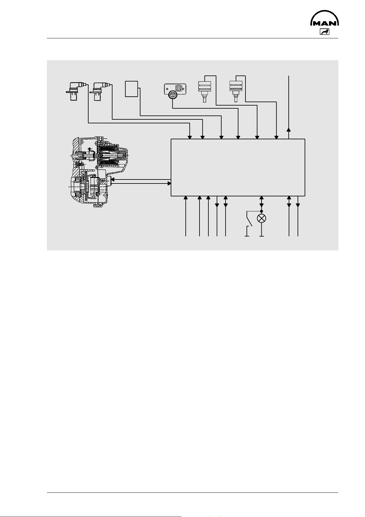
System description
Engine
speed 1
Engine
speed 2
Drive stage
selection
Boost
pressure
Power supply
Intermediate
engine speeds
Charge air intake
temperature
Coolant
temperature
Control unit
PWM signal
terminal 30
Terminal 15
ISO diagnosis
Diagnosis
request
EHAB
Electrohydraulic cut-out
Diagnosis
warning lamp
CAN bus
Engine speed
The controller contains
– the linear solenoid
– the control rod position transducer
The linear solenoid is actuated by the electronic control unit. The control unit processes information which it
receives via
– the control rod position transducer
– the drive position selection
– drive stage selection
– coolant temperature sensor
– charge-air temperature sensor
– intermediate engine speed setpoint
– and the rpm sensors.
The diagnosis request push button and the EDC indicator lamp are used in detecting faults and signalling
them through a code.
An ISO interface provides a communication with the MAN-cats test and diagnostic computer.
The control unit, with its program adapted to the engine model concerned, determines the optimum setting
of the control rod from all the measured values.
To ensure the vehicle can still be driven to the nearest workshop in the event of one or several sensors fail-
ing, an emergency drive function is integrated in the control unit which, depending on the situation, makes it
possible to continue driving with restricted functions.
When the brakes are applied, the system operates as an intermediate engine speed controller with a cyclic
irregularity (P-degree) of 0, i.e. a set intermediate engine speed is maintained exactly provided the engine
develops sufficient power output for this purpose.
7
Page 10

System description
The idle speed control operates in the same way as the intermediate engine speed control. The idle speed
is exactly maintained by means of the idle speed governor as long as the engine output is sufficient for this.
The regulated idle speed can be varied within certain limits.
Starting-fuel delivery is output when either a lower start recognition speed is exceeded. The starting fuel
volume and cold idle speed are limited as a function of the coolant temperature to avoid impermissible
smoke emission and unnecessary revving of the engine after starting.
8
Page 11
Component description
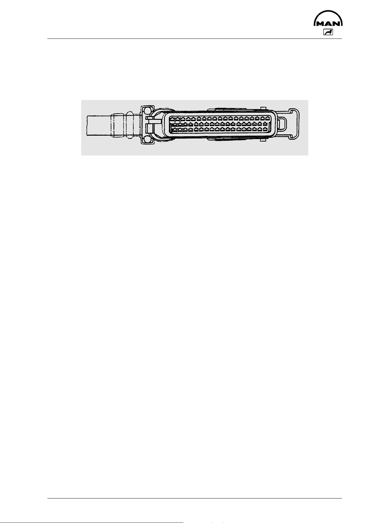
Control unit plug connector
Pin arrangement
19 1. . . . . . . . . . . . . . . . . . . . . . .
37 20. . . . . . . . . . . . . . . . . . . . . .
55 38. . . . . . . . . . . . . . . . . . . . . .
Pin assignments of control unit plug connector
EDC Pin Connection to component (O=Output, I=Input)
1 Injection pump controller pin 8 O
Jumper to pin 2 (activation of fuel volume regulator) O
2 Jumper to pin 1 (activation of fuel-delivery regulator) O
3 Not used
4 Not used
5 Not used
6 Not used
7 Not used
8 Not used
9 Injection pump controller pin 5 (control rod position sensor, instrument coil)
10 Injection pump controller pin 1 (control rod position sensor, reference coil)
11 Injection pump controller pin 6 (control rod position sensor, centre pick-off)
12 Not used
13 Negative from control unit for (Sensor ground)
– rpm sensor
– turbo pressure sensor
– drive stage selection
– turbo air temperature sensor
– coolant temperature sensor
– resistor bank
14 Electrohydraulic shut-off valve (EHAB) O
15 Control unit power supply battery + (via main relay and fuse) I
16 Control unit power supply battery + (via main relay and fuse) I
17 Ground for auxiliary rpm sensor
18 Power supply battery –
19 Power supply battery –
20 EDC indicator lamp and diagnostic lamp O
21 RPM sensor (twisted with cable pin 13) I
22 Auxiliary rpm sensor (twisted with cable pin 17) I
23 Intermediate engine speed control ZDR 1 I
24 Not used
25 Not used
9
Page 12

Component description
EDC Pin Connection to component (O=Output, I=Input)
26 Not used
27 Drive stage selection (signal) I
28 Engine speed signal output from control unit (square-wave pulses) O
29 Multiplex signal O
30 CAN-L
31 CAN-H
32 Not used
33 Turbo pressure sensor (supply) O
34 Turbo air temperature sensor I
35 Resistor bank
36 Turbo pressure sensor (signal) I
37 Not used
38 Not used
39 Empty fuel switch signal
40 External engine cut-out
41 Intermediate engine speed control ZDR 2 I
42 Not used
43 Not used
44 Speed control device I
45 Drive stage selection (supply)
46 Relay power supply batt.+ (main relay) O
47 Relay power supply n/o contact I
48 Diagnostic connection (K-link)
49 Diagnostic connection (L-link)
50 Not used
51 Resistor bank 3 kΩ
52 Assigned to batt.+ (to enable multiplex signal) I
53 Coolant temperature sensor I
54 Not used
55 Not used
10
Page 13
Component description
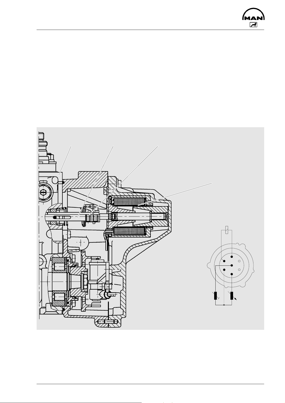
Injection pump
The EDC injection pump consists of a heavy-duty version of a conventional injection stage of the wellknown Bosch P-pumps and, instead of the mechanical regulator, a flange-mounted electromagnetic fueldelivery regulator with a control rod position transducer.
Electromagnetic fuel-delivery regulator
Description:
The fuel-delivery regulator operates in conjunction with the P-pump. The most important component of the
fuel-delivery regulator is a linear solenoid whose armature acts directly on the control rod thus determining
the injection volume by means of the control position. When no power is applied, the control rod is held in
the stop position by means of a spring.
The other important component in the regulator is a control rod position sensor.
Injection pump
Control rod Control rod position sensor
Fuel delivery regulator
(linear solenoid)
Fuel-delivery regulator
2
7
1
6
3
4
5
11
Control rod position sensor
Plug connection
Page 14
Component description
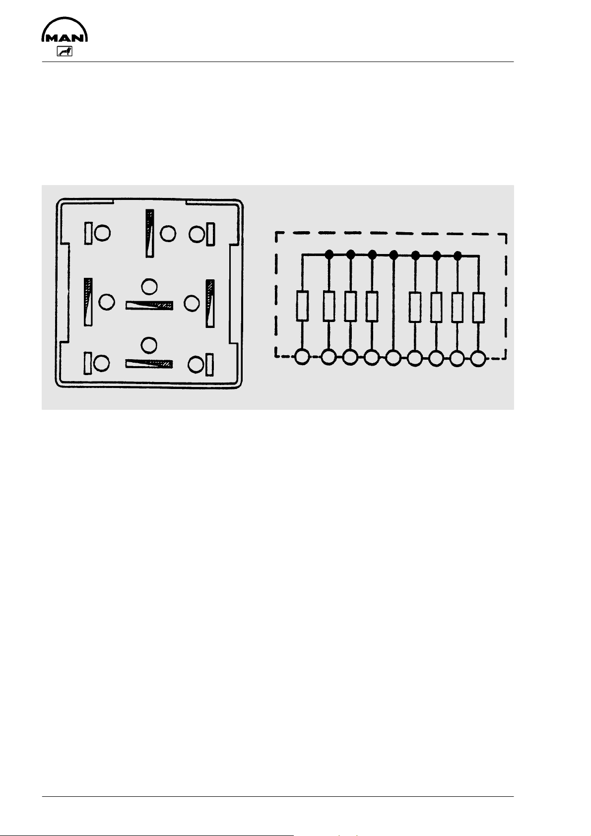
Resistor bank
On commercial vehicles, certain items of data are fed to the EDC which are not required for railway operation.
An example of such data is a signal from the tachograph (speedometer, tachograph) which is used for controlling or limiting the driving speed (see Page 36).
Some unused EDC connections must be closed by resistors since the EDC constantly conducts a signalrange check, as described on Page 21.
Interior circuit
3
1
2
5
6
4
R1 0.511 kOhm
R5 0.511 kOhm
R2 1.37 kOhm
R6 1.37 kOhm
R7 3.08 kOhm
R3 3.08 kOhm
R8 8.20 kOhm
R4 8.20 kOhm
8
9
7
2 84357691
12
Page 15
Component description
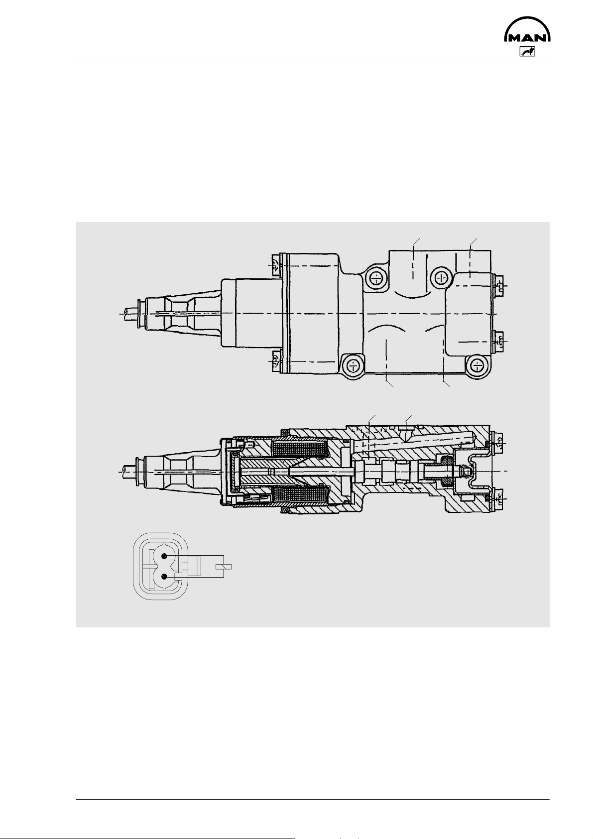
Electrohydraulic shut-off device EHAB
The EHAB (electrohydraulic shut-off device) is a safety-relevant component.
The EHAB shuts off the fuel supply to the injection pump in the event of certain faults occurring in the EDC
system. The EHAB is connected into the fuel supply system between the delivery pump and pump suction
chamber. The EHAB reverses the delivery direction of the delivery pump so that the pressure in the suction
chamber is reduced rapidly thus interrupting the filling procedure.
Power is always applied to the EHAB during operation. The power circuit is interrupted by the EDC control
unit in order to activate the EHAB (e.g. for emergency engine shut-down).
For this reason, the ignition must be turned on when bleeding the fuel system by means of the presupply pump.
21
TÜV
2
1
Plug connection
Fi FP
43
56
13
Page 16
Component description
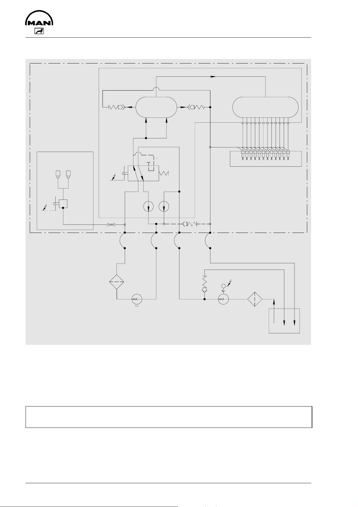
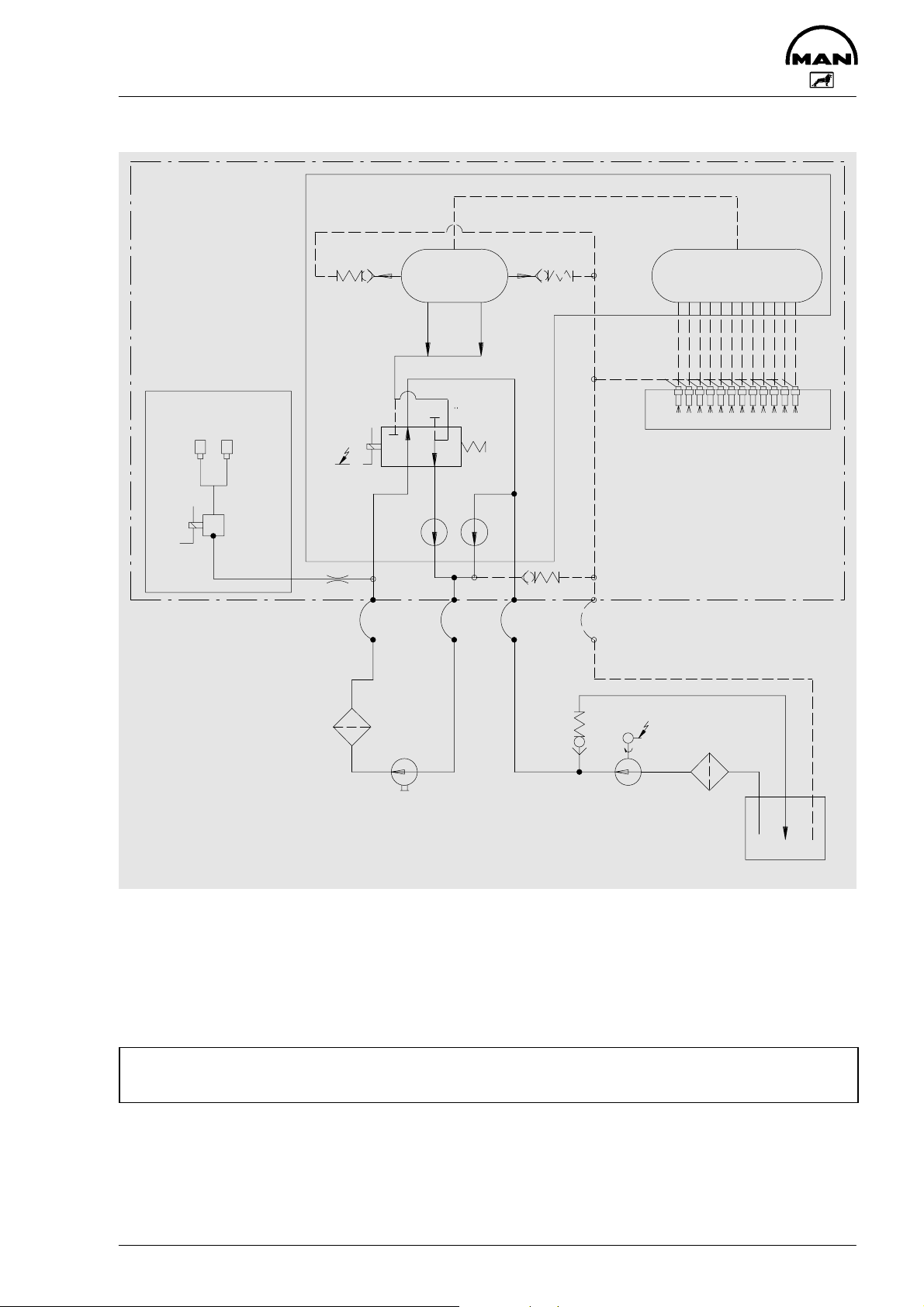
Fuel circuit diagram – Engine running
Injection pump
Flame starting
system
11 11
10
6
9999
Suction
chamber
TUV
3
Fi
Fp
44
6
7
Pressure chamber
Injection nozzles
Engine
5
8
1 Fuel tank 7 Overflow valve 3.7–4.3 bar
2 Prefilter 8 Pre-delivery pump (hand primer)
3 Electrohydraulic shut-off device (EHAB) 9 Fuel hose NW12
(overrevving protection) 10 Magneto valve
4 Delivery pump (double acting) 11 Flame heater plugs
5 Fuel filter 12 Electric fuel pump
6 Overflow valve 2.0–2.5 bar 13 Overflow valve 1.0 bar
Caution:
Presupply pump integration in the fuel circuit should be checked according to pump type.
13
M
12
2
1
14
Page 17
Component description
Fuel circuit diagram – engine shutoff using EHAB
Injection pump
Flame starting
system
11 11
10
6
Suction
chamber
T
UV3
Fi Fp
44
9999
6
7
Pressure chamber
Injection nozzles
Engine
5
8
1 Fuel tank 7 Overflow valve 3.7–4.3 bar
2 Prefilter 8 Pre-delivery pump (hand primer)
3 Electrohydraulic shut-off device (EHAB) 9 Fuel hose NW12
(overrevving protection) 10 Magneto valve
4 Delivery pump (double-acting) 11 Flame heater plug
5 Fuel filter 12 Electric fuel pump
6 Overflow valve 2.0–2.5 bar 13 Overflow valve 1.0 bar
Caution:
Presupply pump integration in the fuel circuit should be checked according to pump type.
13
M
12
2
1
15
Page 18
Component description
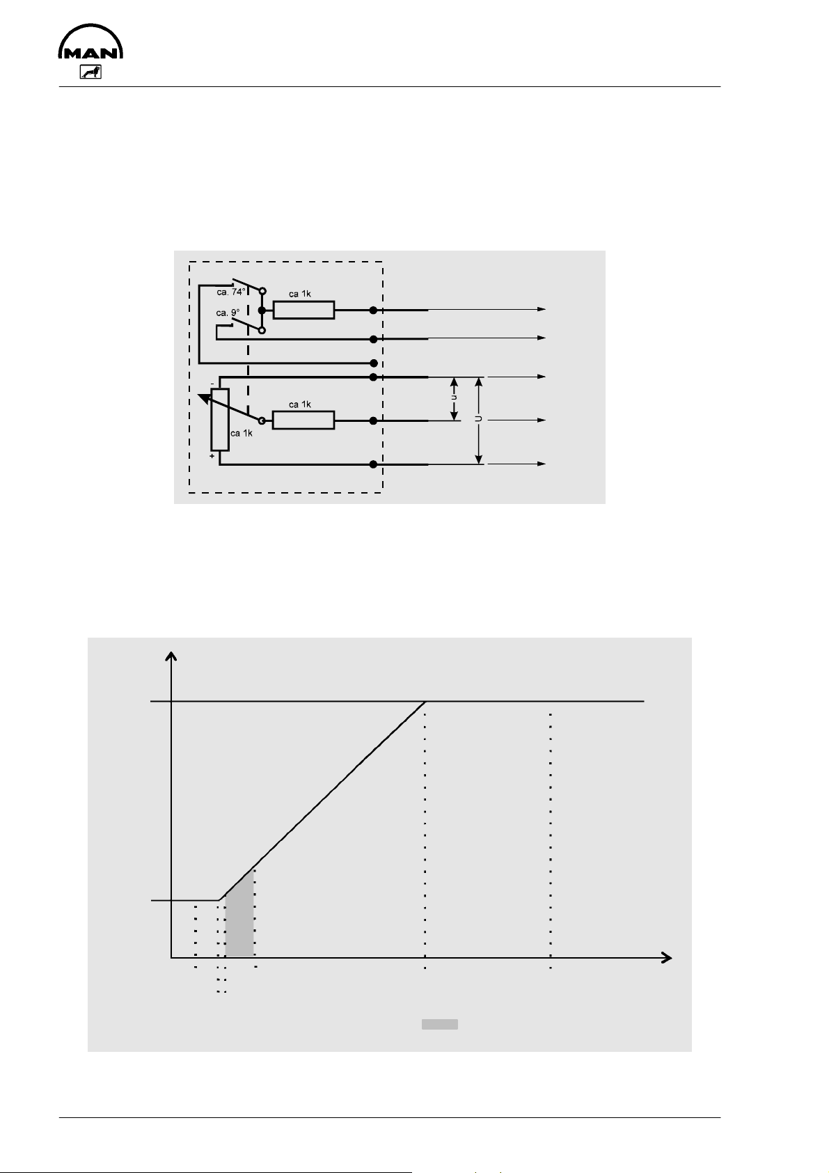
Drive stage selection
Function
The drive stage selection device transfers driver’s requests in the form of voltages to the control unit.
The control unit then derives the corresponding engine speed or volumetric charge from these voltages.
Block diagram
Pin 13
Pin 39
Pin 13
Pin 27
U = Reference voltage, approx. 5 V from the EDC control unit
u = Setpoint
Pedal travel sensor simulation values
Lower idle speed: 257–539 mV / upper idle speed: 2944–4501 mV
Empty fuel switch: switch-on point at 569–976 mV (typically 800 mV)
top idle
speed
Pin 45
lower idle
speed
257 mV 976 mV 2944 mV 4501 mV [ mV ]
539 mV 569 mV
Fault registration
Empty fuel switch range
(typically 880 mV)
Exceptionally, the voltage “u” is produced electronically as drive position selection, or the setpoint selection
(drive position selection) takes place via the CAN bus.
16
Page 19
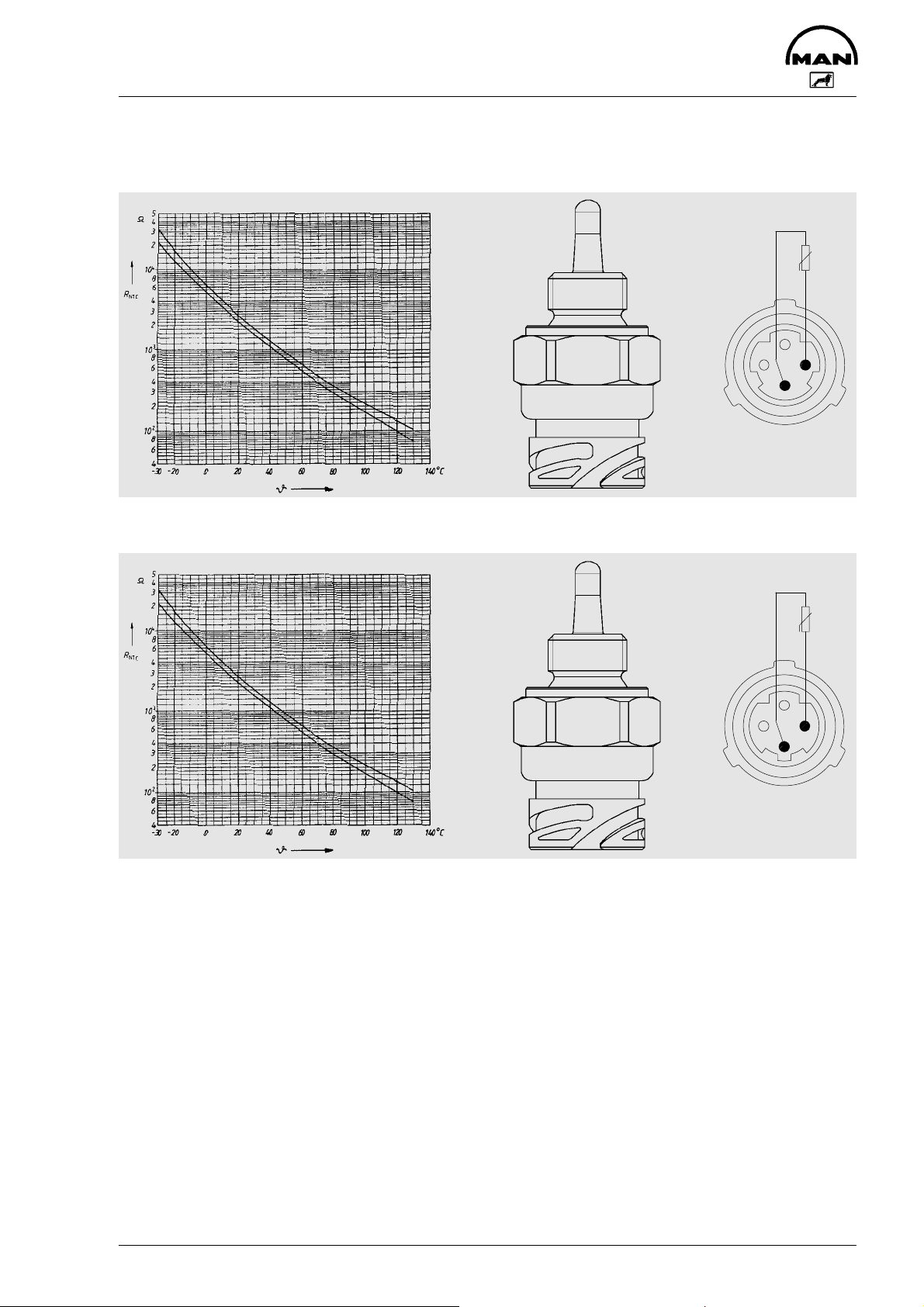
Turbo air and coolant temperature sensors
Turbo air B197 (51.27421–0165)
Characteristic R=f (-í )
Component description
2
4
3
1
Plug connection
Coolant B124 (51.27421–0172)
Characteristic R=f (-í )
2
4
3
1
Plug connection
Function
The turbo air and coolant temperature sensors are NTC resistors. The coolant temperature sensor is located in the coolant circuit and the turbo air temperature sensor in the turbo air circuit after the intercooler.
They supply the control unit with information relating to the coolant and turbo air temperature.
17
Page 20
Component description
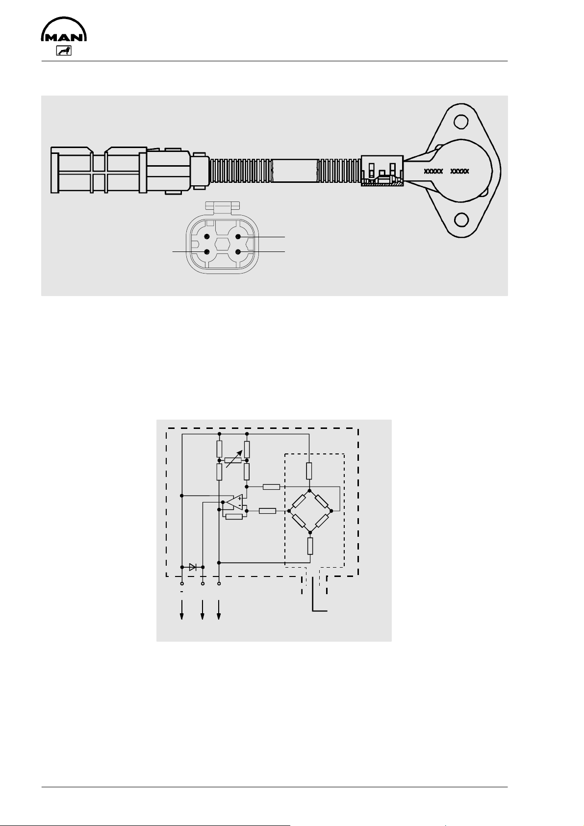
Turbo pressure sensor (51.27421–0181)
1
Ground – Supply +
4
32
Output
Plug connection
Function
The pressure sensor element consists of an Si diaphragm which contains several piezo-resistive (pressuresensitive) semiconductor resistors. The pressure to be measured “deflects” the sprung diaphragms. As a
result, extended or compressed zones are created on the surface of the diaphragms. The action of these
forces changes the electrical ratings of semiconductor resistor arrays arranged in these zones. These values are a measure for the pressure to be measured.
Circuit diagram
Output +5 V
Pin 13 3336
Pressure
connection
18
Page 21
Component description
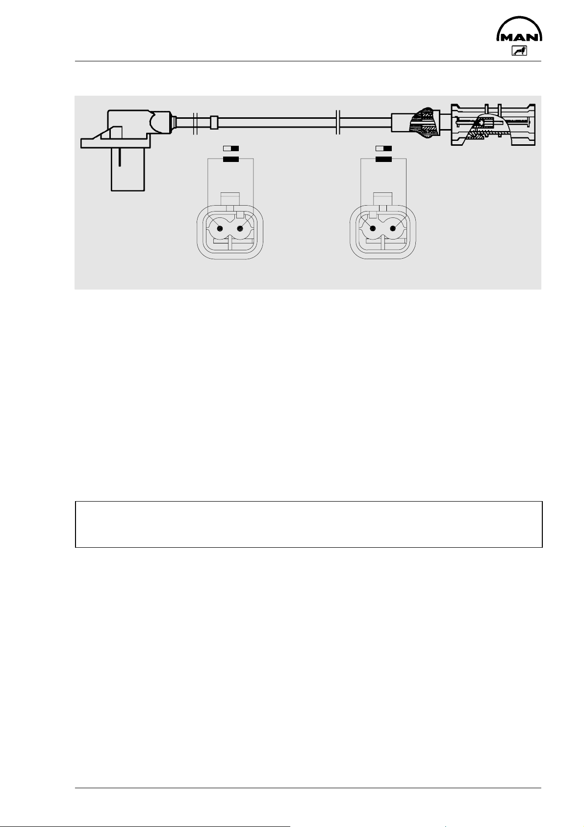
RPM sensor
Housing: grey
Coding A
Function
The rpm sensor consists of a permanent magnet and a coil with a high number of windings. The magnet
“touches” the rotaring component to be measured, normally a crown gear or grooved ring gear, with its
magnetic field.
With the EDC M(S) 5 system, there are 6 grooves on the flywheel.
When a groove passes the sensor, the magnetic current is reduced. This generates an induction voltage in
the sensor coil which is measured by the electronic control. The distance between the sensor and the
grooved ring gear is approx. 1 mm.
Two rpm sensors are required to ensure reliable operation of the EDC system.
Both rpm sensors are installed in the flywheel housing.
A distinction is made between the rpm sensor and the auxiliary rpm sensor.
The rpm sensor is installed in the flywheel housing such that an rpm pulse is triggered 10° after TDC.
The auxiliary rpm sensor is installed in the flywheel housing in such a way that an auxiliary speed pulse is
triggered 18° after TDC. The signals of the auxiliary rpm sensor are used only for redundant engine speed
sensing.
2
Plug connection
RPM sensor (1)
1
Auxiliary rpm sensor (2)
21
Plug connection
Housing: black
Coding B
Caution:
Do not confuse installation locations of the rpm sensor (1) and the auxiliary rpm sensor (2), nor the “+”
and “–” wires of the sensors.
19
Page 22

Notes on operation
Start procedure
The gear stage must be selected (idle speed request setpoint specification) to start the engine.
Changing idle speed
Idle speed setting is possible using EOL programming (MAN Cats), but this should only be performed by
MAN customer service personnel.
Intermediate engine speed control
Different intermediate engine speeds can be programmed by means of MAN-Cats:
D ZDR 1, ZDR 2 and ZDR 3
These intermediate engine speeds are set by corresponding pin connection.
The intermediate engine speeds can be changed using EOL programming (MAN-Cats), but this should only
be performed by MAN customer service personnel.
20
Page 23

Self-diagnosis
General
The EDC system continuously checks itself by means of a signal-range check. It does this by running a
signal-range check. During this check, all signals are scanned for presence and plausibility within a certain
time frame (determined by the software).
The control unit itself is also constantly checked the whole time the program is running. The first check is
always carried out when the ignition is turned on.
Any faults occurring during operation are stored for the purpose of subsequent diagnosis.
A maximum of 5 faults can be stored simultaneously in the fault memory. The faults are stored in the order
in which they occurred. If more than 5 faults occur, the least significant fault is deleted.
Fault storage includes
D allocation of fault priority,
D identification of the type of fault,
D recording of fault frequency.
Sporadic faults are recorded by a frequency counter the first time they occur. This means that a certain frequency number is set which is decremented by one during every start procedure. If the fault no longer occurs, it is deleted when the counter reaches zero.
To report the fault, the diagnostic lamp either comes on permanently or remains off, depending on the significance of the fault. If several faults are stored, the steady light has priority over OFF.
Only faults currently present are indicated. Faults which are stored but which are not currently present are
not indicated.
There are two fault memories:
D Fault memory for diagnosis via ISO interface. This memory can be read out and cleared with MAN-Cats
D Fault memory for diagnosis via flash code. The flash code memory can be read out and cleared with the
aid of the diagnosis button
Faults are always entered in both fault memories simultaneously and can be read out even after the ignition
has been switched off and back on again.
Indicator lamp check:
The EDC indicator lamp lights as a lamp test for approximately 2 seconds after the ignition is switched on.
21
Page 24

Self-diagnosis
The following measures are implemented automatically depending on the significance of the fault:
D Changeover to suitable substitute function to enable continued yet restricted operation
D Reduction of engine speed to idle speed (drive stage 0)
D Immediate shut-down of the engine if required for safety reasons. Depending on the type of fault, engine
shut-down is done by reducing the fuel delivery volume to zero or by way of an emergency shut-down
with EHAB
Flash code
To read out the fault memory
D With the engine stationary or running and the “ignition” switched on, press and hold the diagnosis re-
quest button for at least 2 seconds. The diagnosis lamp will not come on
D The flash procedure starts after a pause of approximately 3 seconds. The flash code is divided into long
and short pulses
D The diagnostic system always outputs only one fault at a time. In order to check whether several faults
are stored, the fault scanning procedure must be repeated until the fault that was shown first reappears
Example of a flash code output
On
Lamp
Off
20
18/19
49
0.5 sec
Fault 2x long, 5x short
OFF phase before output: 3 seconds.
ON duration of a long pulse: 2 seconds.
OFF phase between two long pulses: 1 second.
OFF phase between a long and short pulse: 5 seconds.
ON duration of a short pulse: 0.5 seconds.
OFF phase between two short pulses: 0.5 seconds.
To clear fault memory
1. Press request button
2. Switch on ignition
3. Press and hold request button for a further 3 seconds but not longer than 10 seconds
22
Page 25

Self-diagnosis
light
Fault code output MAN M(S) 5 EDC / MS 5 EDC
Overview of flash codes
Number of
flashes
Long Short
0 0 No fault stored
1 Drive stage selection yes b) 31
4 Engine speed sensing (rpm sensor) yes b) 32
5 Turbo pressure sensing yes b) 33
6 Control rod position sensing yes a) 34
7 Coolant temperature sensing yes b) 35
8 Resistor bank no b) 36
10 Fuel volume regulator monitoring yes a) 37
14 Engine speed sensing (auxiliary rpm sensor) yes b) 38
1 1 Turbo air temperature sensing yes b) 39
1 3 Battery voltage sensing no – 40
1 6 Processor coupling defective yes a) 41
1 7 Overrevving yes b) 42
1 12 Resistor bank yes a) 36
1 13 Control box no b) 43
1 15 CAN system yes b) 44
2 5 Main relay sticking no – 45
2 8 Atmospheric pressure sensing yes b) 46
2 13 TSC1-FM (setpoint selection) yes b) 47
3 2 EEPROM processor 1 error yes a) 48
3 3 EEPROM processor 2 error yes a) 49
3 8 Afterrunning not completed no – 50
3 9 Afterrunning watchdog error no b) 51
3 10 Control rod position sensor – loose contact no – 52
– – PBM interface no – 53
– – Redundant cut-out device (EHAB) no – 54
Fault path Steady
light fault
Main-
tained
light
Reset
a) / b)
see
page
a) Reset by “Ignition” Off / On (cold restart)
b) Reset takes place automatically once the fault is rectified
23
Page 26

List of checking procedures
List of checking procedures EDC MS 5
1. Resistance checks
– “Ignition” off, control unit not connected
– Engine temperature [ 25°C
– Socket box connected
– Measure resistance between PIN+ and PIN– with multimeter
PIN+ PIN– Set-point value Measured value
Control rod position sensor 11 9 18–25 Ohms Ohms. . . . . . . . . . . . . . .
11 10 18–25 Ohms Ohms. . . . . . . . . . . . . . .
18 9 >10 MOhms MOhms. . . . . . . . . . . . . . .
18 10 >10 MOhms MOhms. . . . . . . . . . . . . . .
RPM sensor (DZG) 21 13 0.8–1.0 kOhm kOhms. . . . . . . . . . . . . . .
Auxiliary rpm sensor (HZG) 22 17 0.8–1.0 kOhm kOhms. . . . . . . . . . . . . . .
Fuel-delivery regulator 15 1 0.7–1.3 Ohms Ohms. . . . . . . . . . . . . . .
18 1 >10 MOhms MOhms. . . . . . . . . . . . . . .
16 2 0.7–1.3 Ohms Ohms. . . . . . . . . . . . . . .
Ground 13 18 >10 MOhms MOhms. . . . . . . . . . . . . . .
17 19 >10 MOhms MOhms. . . . . . . . . . . . . . .
EHAB 14 18/19 30–70 Ohms Ohms. . . . . . . . . . . . . . .
Coolant temperature sensor 53 13 1.3–3.6 kOhms
Charge-air temperature sensor 34 13 1.3–3.6 kOhms kOhms. . . . . . . . . . . . . . .
Boost pressure sensor 33, 36 13 Resistance measurement not appropriate
Resistor bank 35 13 500–520 Ohms Ohms. . . . . . . . . . . . . . .
51 13 2.8–3.2 kOhms kOhms. . . . . . . . . . . . . . .
1)
Resistance approximately 230–460 W with engine at operating temperature (approximately 80°C)
1)
kOhms. . . . . . . . . . . . . . .
24
Page 27

List of checking procedures
Auxiliary rpm sensor (HZG)
47
18
46
18
2. Test for engine when running and vehicle stationary (gearbox neutral)
– Engine temperature approx. 30°C
– Control unit connected
– Corrective measures
Set-point value Measured value Remark MAN-Cats
RPM sensor (DZG) n-lower idle speed n= ................ rpm Min (low. idle sp.) Engine speed
n-top idle speed n= ................ rpm Max (top idle sp.) (Monitoring 2)
Auxiliary rpm sensor (HZG)
– Measure voltage between PIN+ and PIN– with multimeter
n-lower idle speed n= ................ rpm Min (low. idle sp.) Engine speed
n-top idle speed n= ................ rpm Max (top idle sp.) (Monitoring 2)
Control unit supply
(U-Batt)
Reference voltage
(Uref)
Idle speed switch
(LGS, NO contact)
Charge-air temperature
sensor (LTF)
Water temperature sensor
(WTF)
Boost pressure sensor
(LDF)
Resistor bank
PIN+PIN–Set-point
value [V]
154718
19
453313134.75–5.25
39 13 4.75–5.25
34 13 4.17–2.62 . . . . . . . . . 10–50°C Idle speed 10–50°C
53 13 3.46–1.22 . . . . . . . . . 30–90°C Idle speed 30–90°C
36 13 0.94–1.20
355113130.75–1.25
U-Batt
U-Batt
4.75–5.25
0–2.00
1.10–1.70
> 0.6
Measured
value [V]
. . . . . . . . .
. . . . . . . . .
. . . . . . . . .
. . . . . . . . .
. . . . . . . . .
. . . . . . . . .
. . . . . . . . .
. . . . . . . . .
. . . . . . . . .
. . . . . . . . .
Remark Engine
Throttle lever min.
Throttle lever max.
Throttle lever min.
Throttle lever max.
Pos 0 Idle speed
speed
Idle speed
Idle speed
idle speed
Top idle sp.
idle speed
Top idle sp.
– Check main relay
PIN+ PIN– Set-point value
Measured value [V] Remark
[V]
Main relay *
47 18
U-Batt . . . . . . . . . . . . . . Ignition on
0V . . . . . . . . . . . . . . Ignition off
46 18
0V . . . . . . . . . . . . . . Ignition on
U-Batt . . . . . . . . . . . . . . Ignition off
* Pin 46 must switch to U-Batt within 0.5 to 5 seconds after ignition has been switched off.
MAN-Cats
(Monitoring)
open
closed
0–100 mbar
300–600 mbar
25
Page 28

List of checking procedures
3. Flash code diagnosis check
– EDC control unit connected
– Socket box connected
– Engine running
Check procedure
– Short-circuit rpm sensor; connect pin 21 to pin 13 to do this
– Diagnosis lamp lights up
– Engine speed is measured by auxiliary rpm sensor
– Disconnect connection between pin 21 and pin 13
– Press diagnosis button for at least 3 seconds but no more than 10 seconds
– Check flash code (4x short = rpm sensor)
– Deleting the fault memory; do this by turning off ignition pressing diagnosis button, turning on ignition,
pressing and holding button for at least 3 seconds but not longer than 10 seconds
4. EHAB check
– Control unit connected
– Socket box connected
– Engine running
Check procedure
– Disconnect pin 14
– Engine should shut down after no more than 10 seconds
5. Capacitance reserve check
The power capacitance of the line leading to the control rod position transducer must not exceed the specified maximum capacitance. The capacitance increases if the line is dirty or moist. This check is designed to
establish how much capacitance reserve is still available.
– Control unit connected
– Socket box connected
Check procedure
– Connect capacitance decade between pin 11 and pin 13
– Connect additional capacitance until the engine no longer starts
– Record value
Setpoint:
>400 pF without wiring harness adapter (capacitance of wiring harness adapter approx. 100 pF),
(wiring harness dry at approx. 25_C)
– Deleting the fault memory
After the checks have been completed, the fault memory must be cleared with MAN-Cats.
No fault must be stored when the “ignition” is turned on again. If this is not the case, the fault must
be located and eliminated in accordance with the troubleshooting procedure.
26
Page 29

Troubleshooting chart
1. EDC self-diagnosis or flash code output
2. Starter turns over engine only slowly or not at all
3. Starter turns, engine does not start, engine does not start / difficult to start when cold
4. Engine stalls (dies) during operation, no longer starts (starter turns), engine does not start / starts with difficulty when hot
5. Sudden, temporary engine shut-down, engine does not reach full revs
6. Engine only runs at idle speed, no throttle response
7. Engine only runs at increased idle speed, no throttle response
8. Rated engine speed distinctly reduced (even under no load)
9. Reduced output in all ranges
10. Irregular engine operation, traction loss
11. Unstable idle speed, engine hunting, misfiring, knocking in engine
12. Engine judder
13. Unusual combustion noise
14. Excessive smoke emission: White smoke / blue smoke
15. Excessive smoke emission: Black smoke
16. Engine temperature too high (coolant loss)
17. Intermediate engine speed control cannot be activated / does not switch off,
engine revs too high
18. Fuel consumption too high
19. Lubricating oil pressure too low
20. Lubricating oil pressure too high
21. Lubricating oil consumption too high
22. Engine too loud / mechanical noise
Possible causes
x x Batteries discharged, battery lead connections loose or corroded, break in power
x Crank gear blocked
x x Starter solenoid switch sticks (clicks) / defective, cable connection loose or dam-
x x Starter / starter interlock relay defective (carbon brushes worked loose / worn,
x x x x Engine oil viscosity unsuitable, not suitable for ambient temperature, lubricating
x x Oil level in sump too high
x Oil level in sump too low, oil in sump too thin (mixed with condensate or fuel)
x Engine temperature too high
x Oil filter clogged
x x Oil pressure gauge faulty
x Safety valve in oil circuit defective (does not close, spring fatigued or broken)
x x Bearing wear
x Oil pump gears worn
x x x Engine cold
x Lubricating oil entering combustion chamber (piston rings worn, piston rings
x x Piston rings heavily worn, broken
x x Piston pin or crankshaft bearing worn
x x x Valve clearance not correct
x x Valves jam
x x x x Compression deficient, or more than 3–4 bar pressure difference between individ-
x x x Valve seats leaking
o x x Increased power consumption due to faulty secondary consumers such as hy-
x x x x x Air cleaner soiled or clogged, charge-air system leaking, air inlet / exhaust lines
x x x x x x x x x Fuel low pressure system: fuel tank, prefilter, water trap faulty / clogged / mould /
circuit
aged
winding defective, short to ground)
oil quality does not correspond to specifications
x Crankshaft timing gears worn, tooth flank backlash too great
broken) – valve stem guide worn – overpressure in crankcase (crankcase vent
clogged)
x Relief valve in oil circuit faulty (does not open), oil lines / oil galleries clogged
x Leaks in lubricating oil circuit, particularly at turbocharger and oil cooler
x Valve stems worn
ual cylinders
draulic pumps, fan, etc, power take-off engaged
clogged / leaking
fungal attack, fuel unsuitable / heavily contaminated (paraffin added)
x = Probable
o = Possible
27
Page 30

Troubleshooting chart
1. EDC self-diagnosis or flash code output
2. Starter turns over engine only slowly or not at all
3. Starter turns, engine does not start, engine does not start / difficult to start when cold
4. Engine stalls (dies) during operation, no longer starts (starter turns), engine does not start / starts with difficulty when hot
5. Sudden, temporary engine shut-down, engine does not reach full revs
6. Engine only runs at idle speed, no throttle response
7. Engine only runs at increased idle speed, no throttle response
8. Rated engine speed distinctly reduced (even under no load)
9. Reduced output in all ranges
10. Irregular engine operation, traction loss
11. Unstable idle speed, engine hunting, misfiring, knocking in engine
12. Engine judder
13. Unusual combustion noise
14. Excessive smoke emission: White smoke / blue smoke
15. Excessive smoke emission: Black smoke
16. Engine temperature too high (coolant loss)
17. Intermediate engine speed control cannot be activated / does not switch off,
engine revs too high
18. Fuel consumption too high
19. Lubricating oil pressure too low
20. Lubricating oil pressure too high
21. Lubricating oil consumption too high
22. Engine too loud / mechanical noise
Possible causes
x x x x x x x x Fuel low pressure system: Fuel lines leaking, broken, clogged
x x x x x x x Fuel low pressure system: AIR in the system
x x x x x x x x x Fuel low pressure system: delivery pump, overflow valve, main filter
x x x x x o x x Fuel high pressure system: nozzles faulty / clogged / leaking / coked
x x x x o Fuel high pressure system: pressure lines – constriction, cavitation, leaking
x x o x x x x o Fuel high pressure system: injection pump worn / incorrectly set
o x o o Fuel high pressure system: injection pump constant-pressure control valve / re-
x x x o x EHAB defective, drive faulty
o o o x o x x x Injection pump / engine synchronisation: start of delivery incorrect (basic installa-
x x x x o x o Injection pump controller: stiff movement – fuel volume regulator (control devi-
x x x x o Control rod position sensor in regulator: connection lines, break, short-circuit
o o o Control rod position sensor in regulator: set incorrectly
x x o Control rod position sensor in regulator: capacitance reserve of the wiring har-
x o x o o Injection pump: fuel volume set incorrectly / uniform delivery, lower idle speed set
x o x x x Delivery actuating solenoid in controller: Connection lines, break, short-circuit, or
x x x x x o Drive stage selection defective:Connection lines, short-circuit, break
x EDC rpm sensor defective, implausible with auxiliary rpm sensor, line defective
x o EDC rpm sensor, polarity reversed
x EDC auxiliary rpm sensor defective, implausible with rpm sensor, line defective
x x x x o o o o EDC detects incorrect engine speed (interference signal on rpm sensor line)
x x x x o Both rpm sensors faulty, line fault
x x x EDC boost pressure sensor: faulty, incorrect, implausible with atmospheric pres-
x x o x Exhaust turbocharger leaking or faulty
x Intercooler leaking, faulty
x x Flame starting system defective
x o x x o x EDC coolant temperature sensor: faulty, line fault
x x x EDC charge-air temperature sensor: faulty, line fault
o x x Radiator dirty or cooling system failure (temperatures too high)
x = Probable
o = Possible
(turn on ignition when bleeding the system)
turn flow constrictor faulty
tion), start of delivery set incorrectly
ation)
ness too low (e.g. water penetrated wiring harness)
too low
CAN-Bus
sure sensor, line fault
x Turbine and compressor rotor in turbocharger dirty (out-of-balance, irregular run-
ning)
28
Page 31

Troubleshooting chart
1. EDC self-diagnosis or flash code output
2. Starter turns over engine only slowly or not at all
3. Starter turns, engine does not start, engine does not start / difficult to start when cold
4. Engine stalls (dies) during operation, no longer starts (starter turns), engine does not start / starts with difficulty when hot
5. Sudden, temporary engine shut-down, engine does not reach full revs
6. Engine only runs at idle speed, no throttle response
7. Engine only runs at increased idle speed, no throttle response
8. Rated engine speed distinctly reduced (even under no load)
9. Reduced output in all ranges
10. Irregular engine operation, traction loss
11. Unstable idle speed, engine hunting, misfiring, knocking in engine
12. Engine judder
13. Unusual combustion noise
14. Excessive smoke emission: White smoke / blue smoke
15. Excessive smoke emission: Black smoke
16. Engine temperature too high (coolant loss)
17. Intermediate engine speed control cannot be activated / does not switch off,
engine revs too high
18. Fuel consumption too high
19. Lubricating oil pressure too low
20. Lubricating oil pressure too high
21. Lubricating oil consumption too high
22. Engine too loud / mechanical noise
Possible causes
x Coolant level too low, air in coolant circuit
x V-belt for water pump drive not tensioned correctly
x Incorrect V-belt tension
x Water pump leaking, faulty / thermostat faulty, does not open
x Coolant lines leaking, clogged or twisted
x Coolant entering combustion chamber (cylinder head / gasket leaking)
x Resistor bank EDC control unit pin 51
x x x o o Power supply to EDC control unit interrupted or battery voltage too low /
x x o o Line terminal 15 to EDC control unit (pin 47) interrupted / loose contact
x Line defective: Pin 23 or 41
x o o o EDC control unit faulty (internal fault)
x x x x o o o x Incorrect EDC control unit (check MAN part number)
x x o Intermediate engine speed activated
x EOL programming terminated / voltage interrupt
x Afterrunning not completed (e.g. shut-down via EMERGENCY STOP)
x EOL programming: configuration incorrect
x Engine bearings worn
Relay K1 faulty
x = Probable
o = Possible
29
Page 32

Troubleshooting program
The following troubleshooting program contains all faults which can be detected by the diagnostic system.
The order corresponds to the numerical sequence of the flash code, irrespective of the significance of the
fault.
It is therefore not arranged on the basis of “fault is indicated by EDC indicator lamp” or “fault is not indicated by EDC indicator lamp”.
The entire fault code memory should always be read out and all stored fault codes noted down before starting the engine test.
This is important because lines or components need to be disconnected when troubleshooting the
system and this can cause the corresponding fault codes to be set and stored.
For this reason, the fault memory should always be cleared after intermediate checks.
The “test lines” test stage must always be performed as follows:
– Break or contact resistance
Set-point value: approximately 0 Ω
– Short to negative
Set-point value: ∞ Ω
– Short to positive
Set-point value: ∞ Ω
– Short to adjacent lines
Set-point value: ∞ Ω
– Loose contacts
After rectifying faults and checking, repeat test and clear fault code memory.
All checks which refer to the control unit plug connector are conducted with the aid of the socket box.
The pin designations on the control unit plug connector are identical to those of the test sockets on the
socket box.
Note:
The connection to the control unit must be disconnected at the socket box when resistance measurements are being carried out.
30
Page 33

Test
Drive stage selection
Flash code: 1x short
Fault indication: Fault is indicated by the EDC indicator lamp coming on continuously
Fault path: Drive stage selection
– Signal too high
– Signal too low
– Signal implausible with idle speed switch
Effect of fault: Engine assumes lower idle speed
Possible cause: Line break, short-circuit, power supply interrupted, drive stage selection defec-
tive, control unit defective
Test precondition: Socket box connected
“Ignition” switched on
Test Measurement Corrective measures
Voltage supply Measure voltage at the socket box across
pin 45 (+) and pin 13 (–)
Setpoint: 4.75–5.25 V
Drive stage selection
PWG Min. 0 %
PWG Max. 100 %
Idle speed switch
Measure voltage at the socket box across
pin 27 (+) and pin 13 (–)
Setpoints:
Idle speed setting: 0.3–0.5 V
Full load setting: 2.9–3.1 V
Measure voltage on the socket box across
pin 39 (+) and pin 13 (–)
– Check lines
– Check plug connections
– If no fault found, replace control
unit (disconnect the control unit
only when the current is
switched off)
– Check lines
– Check plug connections
– Replace drive stage selection
– Check lines
– Check plug connections
PWG Min. 0 %
PWG Max. 100 %
Setpoints:
Idle speed setting: 4.75–5.25 V
Full load setting: 0.0–2.0 V
Switch open
Switch closed
31
Page 34

Test
RPM sensor
Flash code: 4x short
Fault indication: Fault is indicated by the EDC indicator lamp coming on continuously
Fault path: RPM sensor
– Statically implausible
– Dynamically implausible
– Implausible with auxiliary rpm sensor
Effect of fault: If the auxiliary rpm sensor also fails, the engine will be shut down by EHAB
Possible cause: Line break, short to ground, rpm sensor faulty, control unit faulty
Test precondition: Disconnect EDC control unit to ensure the engine cannot start up
Socket box connected
Test Measurement Corrective measures
Resistance Measure resistance at socket box across
pin 21 and pin 13
Setpoint: 800–1000 Ω
Engine speed signal Check signal at socket box at starting
speed across pin 21 (+) and pin 13 (–)
with oscilloscope
Setpoint: see diagram
– Check lines
– Check plug connections
– If no fault found, replace rpm
sensor
U > 2 V
32
Page 35

Test
Boost pressure sensor
Flash code: 5x short
Fault indication: Fault is indicated by the EDC indicator lamp coming on continuously
Fault path: Boost pressure sensor
– Signal too high
– Signal too low
– Signal implausible with atmospheric pressure sensor (in control unit)
Effect of fault: 60 to 70 % reduction in power
Possible cause: Line break, short-circuit, boost pressure sensor faulty, control unit faulty
Test precondition: EDC control unit connected
Socket box connected
“Ignition” switched on
Test Measurement Corrective measures
Power supply Measure voltage at socket box across pin
33 (+) and pin 13 (–)
Setpoint: 4.75–5.25 V
Signal voltage Measure voltage at socket box across pin
36 (+) and pin 13 (–)
Setpoints:
Lower idle speed: 0.94–1.20 V
Upper idle speed: 1.10–1.70 V
If all the values are OK, the atmospheric
pressure sensor in the control unit may be
faulty
– Check lines
– Check plug connections
– If no fault found, replace control
unit (disconnect the control unit
only when the current is
switched off)
– Replace control unit (only dis-
connect control unit once the
current is switched off)
33
Page 36

Test
Control rod position sensor
Flash code: 6x short
Fault indication: Fault is indicated by the EDC indicator lamp coming on continuously
Fault path: Control rod position tranducer
– Signal too high
– Signal too low
Effect of fault: This fault results in the engine being shut down by setting the control rod
travel to 0. The engine cannot be started if this fault is currently present (EDC
indicator lamp permanently on).
Possible cause: Line break, short-circuit, too little capacitance reserve (see page 26), control
rod position sensor set incorrectly, injection pump faulty
Test precondition: EDC control unit disconnected
Corrective measures
Test Measurement Corrective measures
Instrument coil Measure resistance at socket box across
pin 11 and pin 9
Setpoint: 18–25 Ω
Reference coil Measure resistance at socket box across
pin 11 and pin 10
Setpoint: 18–25 Ω
Measure resistance at socket box across
pin 18 and pin 9
Setpoint: > 10 MΩ
Measure resistance at socket box be-
tween pin 18 and pin 10
Setpoint: > 10 MΩ
In addition to the possibility of an electrical
fault, the fault described here may also be
caused by incorrect setting of the control
rod position sensor
– Check lines
– Check plug connections
– If no fault found, repair injection
pump
– Remove injection pump
– Adjust control rod position sen-
sor
34
Page 37

Test
Coolant temperature sensor
Flash code: 7x short
Fault indication: Fault is indicated by the EDC indicator lamp coming on continuously
Fault path: Coolant temperature sensor
Effect of fault: The substitute value provided in the control unit for such cases results in a
reduction in power output (e.g. in the event of radiator contamination or failure
of cooling system).
Possible cause: Line break, short-circuit, temperature sensor faulty, control unit faulty, failure or
contamination of cooling system
Test precondition: EDC control unit disconnected / connected
Socket box connected
Test Measurement Corrective measures
Sensor resistance
(control unit
disconnected)
Sensor voltage
(control unit connected)
Measure resistance at the socket box
across pin 53 and pin 13
Setpoints:
1.3–3.6 KΩ at 15–30°C
230–460 Ω at 75–80°C
Measure voltage at socket box between
pin 53 and pin 13
Setpoint: 3.46–1.22 V at 30–90°C
– Check lines
– Check plug connections
– Replace temperature sensor
– If no fault found, replace control
unit (disconnect the control unit
only when the current is
switched off)
35
Page 38

Test
Resistor bank
Driving speed
Flash code: 8x short
Fault indication: Fault is not indicated by the EDC indicator lamp
Torque limitation
Flash code: 1x long, 12x short
Fault indication: Fault is indicated by the EDC indicator lamp coming on continuously
Driving speed / Torque limitation
Fault path: Resistance for the sensors not present – speed of travel (pin 51) and torque
limit (pin 35)
Resistor bank defective,
Resistance values incorrect
Effect of fault: Reduced final engine speed
Possible cause: Line break, short-circuit, resistor bank defective
Test precondition: EDC control unit disconnected
Socket box connected
Test Measurement Corrective measures
Resistor bank Measure resistance across
Setpoint:
Pin 13 and Pin 35 500–520 Ω
Pin 13 and Pin 51 2.8–3.2 kΩ
– Check lines
– Check plug connections
– If no fault found, replace resistor
bank
36
Page 39

Test
Fuel volume regulator
Flash code: 10x short
Fault indication: Fault is indicated by the EDC indicator lamp coming on continuously
Fault path: Fuel volume regulator control deviation
Effect of fault: The setpoint – actual value comparison for activating the fuel volume regulator
has resulted in a control deviation which has exceeded a specified time
threshold. This fault results in the engine being shut down. The engine can
only be restarted when the fault is no longer present and the ignition is
switched off and on again once.
Possible cause: Line break, short-circuit, injection pump faulty (internal fault in regulator or stiff
movement), capacitance reserve of line leading to control rod position sensor
too low (see page 26)
Test precondition: EDC control unit disconnected
Socket box connected
Test Measurement Corrective measures
Actuating solenoid Measure resistance at socket box across
pin 15 and pin 1, pin 16 and pin 2
Setpoints: 0.7–1.3 Ω
Measure resistance at socket box between pin 18 and pin 1
Setpoint: > 10 MΩ
– Check lines
– Check plug connections
– If no fault found, replace injec-
tion pump
37
Page 40

Test
Auxiliary rpm sensor
Flash code: 14x short
Fault indication: Fault is indicated by the EDC indicator lamp coming on continuously
Fault path: Auxiliary rpm sensor
– Statically implausible
– Dynamically implausible
– Implausible with rpm sensor
Effect of fault: If the rpm sensor also fails, the engine will be shut down
Possible cause: Line break, short to ground, auxiliary rpm sensor faulty, control unit faulty
Test precondition: Disconnect EDC control unit to ensure the engine cannot start up
Socket box connected
Test Measurement Corrective measures
Resistance Measure the resistance at the socket box
between pin 22 and pin 17
Setpoint: 800–1000 Ω
Engine speed signal Check signal at socket box at starting
speed across pin 22 (+) and pin 17 (–)
with oscilloscope
Setpoint: see diagram
– Check lines
– Check plug connections
– If no fault found, replace auxili-
ary rpm sensor
U > 2 V
38
Page 41

Test
Charge-air temperature sensor
Flash code: 1x long, 1x short
Fault indication: Fault is not indicated by the EDC indicator lamp
Fault path: Charge-air temperature sensor
Effect of fault: The substitute value provided in the control unit for such cases results in a
reduction in power output (e.g. in the event of radiator contamination or failure
of cooling system).
Possible cause: Line break, short-circuit, turbo air temperature sensor defective, control unit
defective, failure or contamination of cooling system.
Test precondition: EDC control unit disconnected / connected
Socket box connected
Test Measurement Corrective measures
Sensor resistance
(control unit
disconnected)
Sensor voltage
(control unit connected)
Measure resistance at socket box across
pin 34 and pin 13
Setpoint: 1.3–3.6 KΩ at 15–30°C
Measure voltage at socket box across pin
34 and pin 13
Setpoint: 4.17–2.62 V at 10–50°C
– Check lines
– Check plug connections
– Replace temperature sensor
– Check cooling system
– If no fault found, replace control
unit (only disconnect the control
unit once the current is switched
off)
39
Page 42

Test
Undervoltage
Flash code: 1x long, 3x short
Fault indication: Fault is not indicated by the EDC indicator lamp
Fault path: Control unit power supply (battery voltage too low)
Effect of fault: The EDC system or the engine can behave in various ways depending on the
magnitude of the voltage drop:
– No power
– Highly irregular engine operation
– No engine operation
– Excessive smoke emission
– Contradictory fault memory entries
Possible cause: Battery discharged or faulty, alternator faulty, line break, short-circuit, main
relay faulty
Test precondition: EDC control unit disconnected
Socket box connected
“Ignition” switched on
Test Measurement Corrective measures
Voltage supply To activate the main relay K1, connect
jumper across pin 46 and pin 19
Measure voltage at socket box across
pins 15/16 (+) and pins 18/19 (–)
Setpoint: 24–28 V
– Check lines
– Check plug connections
– Replace main relay
40
Page 43

Test
Control unit
Flashcode: 1x long, 6x short
Fault indication: Fault is indicated by the EDC indicator lamp coming on continuously
Fault path: Control unit fault (processor coupling)
Effect of fault: Engine is shut down by “no power applied to fuel delivery output stage” and
control position set to 0
If this fault occurs only temporarily, the engine can be restarted after switching
the “ignition” off and on again
Possible cause: Undervoltage (loose contact), control unit fault
Test precondition: EDC control unit connected
Test Measurement Corrective measures
The controller contains This fault signal can also occur in the
event of extremely low power supply
(loose contacts or undervoltage)
Internal fault in control unit
– Check lines
– Check plug connections
– Replace control unit (only dis-
connect the control unit once the
current is switched off)
41
Page 44

Test
Engine overspeed
Flash code: 1x long, 7x short
Fault indication: Fault is indicated by the EDC indicator lamp coming on continuously
Fault path: Engine overspeed
Effect of fault: Fuel delivery is interrupted. EHAB is deactivated.
If no other fault is present, fuel delivery will continue once the engine overspeed range has been left.
Possible cause: Stiff control rod. Injection pump defective, control unit defective, wiring har-
ness defective, engine being towed
Test Measurement Corrective measures
If no other faults are present, no further
action is necessary
Injection pump If the fault occurs more frequently, check
injection pump, control unit and lines.
– Deleting the fault memory
– Replace lines
– Replace control unit (disconnect
control only when current is
switched off)
– Replace injection pump
42
Page 45

Test
EDC control box for idle speed adjustment
Flash code: 1x long, 13x short
Fault indication: Fault is not indicated by the EDC indicator lamp
Fault path: Operating unit defective
– Voltage values incorrect or implausible
Effect of fault: The idle position can no longer be activated.
If the fault was only temporary (e.g. operating unit activated several times) the
system will be ready for operation after switching the “ignition” off an on again.
Function: The operating unit is resistor-coded, i.e. the control unit recognizes each
switching state according to the voltage level supplied. Faults are detected
when incorrect values are output over a certain period of time; e.g. electrical
fault or multiple operation (incorrect operation) of the operating unit.
Possible cause: Line break, short-circuit, operating unit defective, incorrect operation
Test precondition: EDC control unit connected
socket box connected
ignition switched on
Test Measurement Corrective measures
Control box Measure voltage at the socket box across
pin 44 and pin 13
Switch through all settings of the operating unit and determine relevant voltage
value
Setpoints:
SET+: 0.65–0.97 V
SET–: 2.31–2.75 V
MEMORY: 1.41–1.81 V
OFF: 3.72–4.33 V
Not activated: 3.15–3.55 V
– Check lines
– Check plug connections
– Replace the control box
– If no fault found, replace control
unit as a check (disconnect the
control unit only when the current is switched off)
43
Page 46

Test
CAN system (control unit)
Flash code: 1x long, 15x short
Fault indication: Fault is indicated by the EDC indicator lamp coming on continuously
Fault path: Control unit faulty
Effect of fault: The data exchange has been interrupted. Some engine data (speed, tempera-
ture of water and charge air, boost pressure and fuel consumption) no longer
displayed.
Possible cause: Line break, short-circuit
Test Measurement Corrective measures
Control unit No further testing necessary – Replace control unit (only dis-
connect the control unit once the
current is switched off)
44
Page 47

Test
Main relay
Flash code: 2x long, 5x short
Fault indication: Fault is not indicated by the EDC indicator lamp
Fault path: Main relay
Contact sticks or jams (does not open)
Effect of fault: Under certain conditions, this fault may not be detected
Function: The negative side of the relay coil is triggered by the EDC control unit via the
control unit output pin 46. The main relay switch-off is delayed after the ignition is switched off (run-on).
During the afterrunning phase, various processor functions are checked and
any faults stored in the fault code memory.
Possible cause: Short to ground, main relay faulty
Test precondition: EDC control unit connected
Socket box connected
Test Measurement Corrective measures
Main relay Measure voltage at the socket box across
pin 47 and pin 18.
Setpoints:
0 V at “ignition” off
U-Batt at “ignition” on
Measure voltage at socket box across pin
46 and pin 18
Setpoints:
U-Batt at “ignition” off
0 V at “ignition” on
Note: Pin 46 must switch to U-Batt within 5 seconds of the ignition being switched off (processor
run-on).
– Check lines
– Check plug connections
– If line OK, replace main relay
45
Page 48

Test
Atmospheric pressure sensor (in control unit)
Flash code: 2x long, 8x short
Fault indication: Fault is indicated by the EDC indicator lamp coming on continuously
Fault path: Atmospheric pressure sensor in control unit faulty
Effect of fault: The power reduction at high altitudes for the protection of the exhaust turbo-
charger is not activated
Possible cause: Control unit faulty
Test Measurement Corrective measures
Control unit If only this fault code is stored in the
memory, testing is not possible, as the
sensor is located in the control unit.
If, however, a faulty boost pressure sensor is also detected, this should be
checked first in accordance with the boost
pressure sensor test (page 33).
– Replace control unit (only dis-
connect the control unit once the
current is switched off)
46
Page 49

Test
CAN system (TSC1-FM message)
Flash code: 2x long, 13x short
Fault indication: Fault is indicated by the EDC indicator lamp coming on continuously
Fault path: EDC – CAN communication is faulty
Effect of fault: Idle speed
Possible cause: Power interruption
Test precondition: EDC control unit and CAN computer disconnected
Socket box connected to EDC plug
Test Measurement Corrective measures
Resistance
Resistance measurement between pin 30
(CAN-L) on the socket box and a downstream computer
Setpoint: 0 Ω
Resistance measurement between pin 31
(CAN-H) on the socket box and a downstream computer
Setpoint: 0 Ω
– Check line
– Check plug connection
47
Page 50

Test
Replace control unit (only
Control unit, EEPROM processor 1 fault
Flash code: 3x long, 2x short
Fault indication: Fault is indicated by the EDC indicator lamp coming on continuously
Fault path: Processor 1 in control unit faulty (EEPROM 1)
Possible cause: Control unit faulty, EOL programming not completed (voltage supply inter-
rupted)
Effect of fault: Engine is shut down
Engine will not start
Test Measurement Corrective measures
Voltage supply
Control unit
No further testing necessary – Complete EOL program-
ming, clear fault codes
– Replace control unit (only
disconnect the control unit
once the current is switched
off)
48
Page 51

Test
Replace control unit (only
Control unit, EEPROM processor 2 fault
Flash code: 3x long, 3x short
Fault indication: Fault is indicated by the EDC indicator lamp coming on continuously
Fault path: Processor 2 in control unit faulty (EEPROM 2)
Possible cause: Control unit faulty, EOL programming not completed (voltage supply inter-
rupted)
Effect of fault: Engine is shut off
Engine will not start
Test Measurement Corrective measures
Voltage supply
Control unit
No further testing necessary – Complete EOL program-
ming, clear fault codes
– Replace control unit (only
disconnect the control unit
once the current is switched
off)
49
Page 52

Test
Control unit (processor run-on)
Flash code: 3x long, 8x short
Fault indication: Fault is not indicated by the EDC indicator lamp
Fault path: Control unit
– Processor run-on did not take place
Effect of fault: No direct effect
Function: Every time the engine is turned off, run-on takes place automatically for the
purpose of checking the various processor functions
Possible cause: Control unit faulty, main relay faulty, battery voltage switched off before “igni-
tion” off.
Test precondition: EDC control unit disconnected
Socket box connected
Test Measurement Corrective measures
Control unit Test same as for undervoltage (page 40) and
main relay (page 45)
Other possible causes
– Engine was shut down via battery + (e.g. by disconnecting the battery or actuating the main fuse switch)
– Power supply fault (e.g. undervoltage, main relay faulty, loose contact)
– Switch ignition on and off
again, clear fault code
– Same as pages 40 and 45
– Replace control unit (only
disconnect the control unit
once the current is switched
off)
50
Page 53

Test
Control unit watchdog run-on fault
Flash code: 3x long, 9x short
Fault indication: Fault is not indicated by the EDC indicator lamp
Fault path: Control unit faulty (watchdog test)
Effect of fault: None
Test Measurement Corrective measures
Control unit No further testing necessary – Replace control unit (only dis-
connect the control unit once the
current is switched off)
51
Page 54

Test
Control rod position sensor – loose contact
Flash code: 3x long, 10x short
Fault indication: Fault is not indicated by the EDC indicator lamp
Fault path: Control rod position tranducer
– Signal too high
– Signal too low
Effect of fault: None
Possible cause: Line break, short-circuit, too little capacitance reserve (see page 26), control
rod position sensor set incorrectly, injection pump faulty
Test precondition: EDC control unit disconnected
Socket box connected
Test Measurement Corrective measures
Instrument coil Measure resistance at socket box across
pin 11 and pin 9
Setpoint: 18–25 Ω
Reference coil Measure resistance at socket box across
pin 11 and pin 10
Setpoint: 18–25 Ω
Measure resistance at socket box across
pin 18 and pin 9
Setpoint: > 10 MΩ
Measure resistance at socket box be-
tween pin 18 and pin 10
Setpoint: > 10 MΩ
In addition to the possibility of an electrical
fault, the fault described here may also be
caused by incorrect setting of the control
rod position sensor
– Check lines
– Check plug connections
– If no fault found, repair injection
pump
– Remove injection pump
– Adjust control rod position sen-
sor
52
Page 55

Test
PBM interface
Flash code: No code
Fault indication: Fault is not indicated by the EDC indicator lamp
Fault path: Control unit input pin 52
– Faulty
– Interrupted
Effect of fault: No PBM signal at pin 29 (steady voltage U-Batt)
Possible cause: short to negative, line break
Test precondition: EDC control unit connected
Socket box connected
“Ignition” switched off
Test Measurement Corrective measures
Lines
Note: Battery voltage must be applied at pin 52 against pin 18/19 with the “ignition” switched on.
Measure resistance at socket box across pin
52 and pin 19
Setpoint: ∞ Ω
Measure resistance at socket box across pin
29 and pin 19
Setpoint: ∞ Ω
– Check line
– Replace control unit
53
Page 56

Test
Electrohydraulic shut-off device EHAB
Flash code: No code
Fault indication: Fault is not indicated by the EDC indicator lamp
Fault path: EHAB function
Effect of fault: Engine is shut down
Engine will not start (in this case it is assumed, that the fuel supply is OK)
Function: The EHAB performs an important safety function in its capacity as an indepen-
dent, higher-ranking (redundant) engine shut-off device
The EHAB is activated in certain emergency situations when the engine can
no longer be shut off by controlling fuel delivery to zero – e.g. when the control
rod has jammed.
The EHAB reduces the pressure in the suction chamber of the injection pump,
thus interrupting filling.
Possible cause: Line break, short-circuit, EHAB defective, faulty activation from control unit
(control unit defective)
Test precondition: EDC control unit connected
Socket box connected
Test Measurement Corrective measures
Coil resistance Switch off “ignition”
Disconnect control unit
Measure resistance at socket box across pin
14 and pin 19
Setpoint: 30–70 Ω
Voltage supply Switch on “ignition”
Measure voltage at socket box across pin 14
(+) and pin 19 (–)
Setpoint: U-Batt
Note:
When bleeding the fuel system using the presupply pump, power must be supplied to the EHAB, i.e. the
fuel system cannot be bled without the “ignition” being switched on.
See page 26 for function test.
– Check line
– Replace control unit
– Replace EHAB
– Check line
– Replace control unit
– Replace EHAB
If no fault found:
– Replace control unit (only
disconnect control unit
once the current is
switched off)
54
Page 57

Plug connections
Pin No. Abbreviation Description
1 MES O Activation for fuel-delivery actuator
– Output, fuel-delivery control circuit
–I
11 A temporarily, on average 4.5 A, against batt.+, pulsed f=variable, pulse-width modulated
max
2 MES O Activation for fuel-delivery actuator
– Output, fuel-delivery control circuit
3 VHS O Not used
4 VHS O Not used
5 MBR 1 Not used
6 LEB 1 Not used
7 WGS 1 Not used
8 LKS 1 Not used
9 RWG M Control rod position transducer measuring coil (RWG 2)
– Control rod position evaluator circuit
10 RWG R Control rod position transducer reference coil (RWG O)
– Control rod position evaluator circuit
11 RWG Y Control rod position transducer centre pick-off (RWG 1)
– Control rod position evaluator circuit
12 CAN O Not used
13 GND A Sensor ground
14 EAB 1 Electrical shut-down
– Output (switch)
–I
1 A, U
max
15 Bat + Batt.+ via main relay
– Input battery +
– I with engine stationary 0.9 A, idle speed 1.5 A, operation 4.5 A, temporarily 16 A
16 Bat + Batt.+ via main relay
– Input battery +
17 NBF 0, HZGO Needle movement sensor and auxiliary rpm sensor
– Reference ground
18 Bat – Battery negative
– Input battery –
– I same as batt.+ (terminals 15 and 16)
19 Bat – Battery negative
– Input battery
20 DIA-B Diagnosis lamp
– Output (switch)
–I
1 A, U
max
21 DZG 1 RPM sensor signal
– Input, dynamic
– Alternating voltage UPP idle speed approx. 2 V , max. 80 V, f=number of cyl. XN sec.
22 HZG 1 Auxiliary rpm sensor signal
– Input, dynamic
– Alternating voltage UPP idle speed approx. 2 V , max. 80 V, f=number of cyl. XN sec.
23 ZDR-E1 Intermediate engine speed control 1
– Input, static
– Batt. +
24 BRK-E Not used
25 FMS-E Not used
26 KUP-E Not used
27 PWG 1 Pedal travel sensor signal
– Input, analog
– Direct voltage, U approx. 0.4 to 4 V
28 TDS-A Engine speed signal
– Output
–U
against batt. –, square-wave signal, f=number of cyl. X N sec.
batt.
29 MPS-A Multiplex signal
– Interfaces
against batt. –,
batt.
against batt. –,
batt.
–1
–1
–1
55
Page 58

Plug connections
Pin No. DescriptionAbbreviation
30 CAN-L Controller Area Network
– Interfaces
31 CAN-H Controller Area Network
– Interfaces
32 NBF 1 Needle movement sensor
– Input, dynamic
–UPP approx. 2 V
33 LDF 2 Boost pressure sensor
– Output, supply
– Controlled direct voltage, U approx. 5 V
34 KTF 1 Fuel temperature sensor (used for turbo air temperature)
– Input, analog
35 MDB 1 Multi-stage input (torque limitation)
– Input, analog
– Input by change in resistance
36 LDF 1 Boost pressure sensor signal
– Input, analog
37 FGB 1 Not used
38 EOL E Not used
39 LGS-E Idle speed switch signal
– Input, static
– against GND-O (terminal 13)
40 MST-E External engine cut-out
41 ZDR-E2 Intermediate engine speed control 2
– Input, static
Batt.+
42 MBR-E Not used
43 BRE-E Not used
44 FGR 1 Speed control device
45 PWG 2 Pedal travel sensor
– Output, supply
– Controlled direct voltage, U approx. 5 V
46 HRL O Main relay
– Output (switch)
–I
0.3 A, batt. – against batt.+
max
47 K15-E Terminal 15, digit. Data for control unit
– Input, static
– Batt. +
48 ISO-K ISO-K link to ISO protocol
– Interfaces
49 ISO-L ISO-L link to ISO protocol
– Interfaces
50 TKS-E Door contact switch
– Input, static
– Batt. +
51 FGG 1 Driving speed sensor signal
– Input, dynamic
– Square-wave voltage UPP 8.5 V , f. variable
52 PB1-E Pulse-width modulated input signal 1
– Interface
53 WTF 1 Coolant temperature sensor
– Input, analog
54 HGB 1 Multi-stage input, maximum speed limitation
– Input, analog
– Input by change in resistance
55 LTF 1 Not used
56
Page 59

Rating data sheet
1. Revision list
Date Revisions
30.05.1994 First issue
26.04.1999 New edition
2. Scope
This data sheet comprises the specifications and tests for the electronic control unit EDC-MS5 re-
quired to guarantee the functions listed in the following under the specified ambient conditions.
3. General features
3.1 Place of installation Frame (chassis)
3.2 Electrical connection 55-pin plug connection
3.3 Weight approx. 1.4 kg
3.4 Degree of protection
Protection against shock-hazard
and foreign bodies in accordance with DIN 40 050, Part 9; IP 54 A
Protection against water ingress
with connector plugged in in accordance with DIN 40 050, Part 9; IP 54 A
without protecting sleeve in accordance with DIN 40 050, Part 9; IP 30
57
Page 60

Rating data sheet
4. Temperature range
Ta: Temperature of mounting surface
Tu: Temperature of ambient air
4.1 Storage temperature
Permanent, not installed –40°C ... +85°C
Temporary, max. 1h in installed position –40°C ... +100°C
4.2 Operating temperature
Still air
Ambient temperature Tu, permanent –40°C ... +65°C
Mounting surface Ta, permanent –40°C ... +65°C
Moving air
Ambient temperature Tu, permanent –40°C ... +70°C
Mounting surface Ta, permanent –40°C ... +70°C
Tu =Ta, temporary –40°C ... –85°C
See diagram:
Tu= Ta
85°C
70°C
*
*
–
0 5 t [min.]
Control unit switched off Control unit switched on
58
Page 61

Rating data sheet
5. Mechanical characteristics
5.1 Vibration stress
5.1.1 Sinusoidal vibration test in accordance with DIN 40046 Part 8 ,Fc (IEC 68-2-6)
Max. acceleration amplitude 50 m/s
Frequency range 10 Hz ... 200 Hz
Frequency change rate 1 okt./min.
Test duration 24 h per main coordinate
5.1.2 Broadband noise test in accordance with DIN 40046 Part 22, Fd (IEC 68-2-34)
Total acceleration (effective value) 45 m/s
Frequency range 10 Hz ... 1000 Hz
Test duration 24 h per main coordinate
5.2 Shock stress, test in accordance with DIN 40046 Part 7, (IEC 68-2-27)
Max. acceleration amplitude 1000 m/s
2
2
2
Shock form Semi-sinusoidal
Duration of nominal shock 6 ms
Test duration 3 shocks per main coordinate in
both directions (18 shocks)
The frequency and acceleration value specified in 5.1 and 5.2 apply to the vibration testing table.
59
Page 62

Rating data sheet
6. Electrical ratings
6.1 Supply voltage range
6.1.1 Rated voltage 24 V
6.1.2 Permissible supply voltage 7.0 ... 32 V normal operation
(measured at the batt.+, batt.– min. 16 V for 50 ms after switching on terminals
of the control unit) the control unit
The definition provided in Section 7 applies to the voltages U-batt+ ≤ 7 V or U-bat– ≥ 32 V.
6.1.3 Residual ripple of supply voltage (Operation without battery not permitted)
Effective value of supply voltage: U-batt eff = 500 mV max.
(Measured at the batt+, batt– terminals of the control unit with the control unit switched on and the
engine running. The value need not be maintained during the start procedure)
6.2 Power loss, control unit
(idle speed, engine at operating temperature) approx. 18 W
6.3 Polarity reversal protection By coded control unit connector, polarity reversal
of battery does not result in destruction of control
unit when the main relay is activated by the
control unit.
6.4 Short-circuit strength
– Conditions: Max. 1 short-circuit simultaneously For all plug connections against batt+, batt–
– Ta and Tu ≤ 65°C, and against one another except for BAT+, BAT–,
– U-Batt ≤ 28V GND 0. NBF 0. CAN H and L
– control unit is powered with U-batt.
Restricted:
RWGR. RWGM. RWGY short-circuit at
max. 26 V permissible for max. duration of 1 min.
60
Page 63

Rating data sheet
7. Immunity to interference
Pulses in accordance with ISO 7637-2 are permitted on the batt+/batt– line if they are within the fol-
lowing rated values.
The control unit can switch off as a precautionary measure in the case of supply voltages outside the
range 7V ≤ U-Bat+ ≤ 32V.
The function is resumed on returning to the permissible voltage range.
7.1 ISO pulses 1 to 4
Test pulse Vs [Volt] Ri [Ohm] tl [s] Number of
pulses
1a –200 10 5 5 000 –
2 +100 10 0.5 5 000 –
3a –200 50 100µ – 1
3b +200 50 100µ – 1
7.2 ISO pulse 5 (load dump)
Vs = 57 V Ri = 2 Ω td = 200ms (at +U-Batt = 28V)
Set-up temperature Ta ≤ 65°C
Ambient air Tu ≤ 65°C
Minimum wait time between subsequent pulses 1 min
Number of pulses 10
Voltage limitation by the internal load dump feature cuts in at min. 34 V.
7.3 EMV
7.3.1 Irradiation immunity
Frequency range 1 MHz ... 1000 MHz (measure up to 400 MHz)
Test duration [h]
Field strength 100 V/m sinusoidal, non-modulated
(stripline measurement)
Criterion Engine overrevving or shutting down
not permitted.
Accuracy deviation permissible.
7.4 Interference suppression In accordance with VDE 0879 Part 3,
interference suppression level 2.
61
Page 64

Rating data sheet
8. Resistance to motor vehicle-specific liquids / fluids
The control unit is resistant to diesel fuel, petrol, engine oil, engine cleaner, brake fluid, battery acid,
windscreen washer fluid, isooctane / toluene
9. Mechanical test data
9.1 Vibration stress As Point 5.1
9.2 Shock stress As Point 5.2
9.3 Alternating temperature Test Nb in accordance with DIN 40046 Part 14
Clause 3 (IEC 68-2-14 Nb)
Lower test temperature –40°C
Upper test temperature +85°C
Number of cycles 100
Temperature change rate < 10K/min
Holding time at upper stress temperature 15 minutes each
9.4 Moisture resistance
9.4.1 Test in accordance with DIN standard Test Db in accordance with FW 24 DIN 50016
(IEC 68-2-30)
Number of cycles 28
Function test after 7 cycles
9.4.2 Active moisture-alternating temperature test
Rel. humidity 95%
Normal temperature phase at 40°C
Duration 240 h
Low temperature phase at –10°C
Duration 2 h
Changeover time < 3 min
10. Service life test
The service life test comprises a mechanical test in accordance with Points 5.1 and 5.2 as well as a
climatic test in accordance with Points 9.3 and 9.4. Function measurements in accordance with the
test and adjustment specifications are conducted after the individual tests.
62
Page 65

Essential installation in the rail coach
Battery
Main relay
Switch-on relay
Diagnostic lamp
Push button
Flasher code requirement *
Diagnostic plug
MAN Cat
Resistor bank
6
–
+
15A
Terminal 15
Connection diagram
BAT –
LTF 1
FGB 1
BAT –
HGB 1
LFD 1
NBF 0
WTF 1
MDB 1
BAT +
PB1 E
KTF 1
BAT +
FGG 1
LDF 2
EAB 1
TKS E
NBF 1
GND 0
ISO L
CAN H
ISO K
CAN L
RWG Y
K15 E
MPS A
RWG R
HRL 0
TDS A
RWG M
PWG 2
PWG 1
LKS 1
FGR 1
KUP E
WGS 1
BRE E
FMS E
LEB 1
MBR E
BRK E
MBR 1
ZDR E2
ZDR E1
VHS 0
MST E
HZG 1
VHS 0
LGS E
DZG 1
MES 0
EOL E
DIA B
MES 0
46
52
53
54
55
36
Battery –
19
18
2
18/19
2
2.5
87
30
15/16
46
85
86
30
87
47
18/19
85
86
18/19
20
18/19
49
49
Z
18/19
–
A
48
a
15/16
+
D
5
13
54
2
511
1.37K
3
35
51
6
3K
Sensor –
13
Battery +
at Main relay
15
16
2
2
2.5
2.5
Electromagnetic interference suppression
37
17
18
19
2
2
2.5
2.5
51
34
35
16
15
2
2
2.5
2.5
49
50
32
33
13
14
2
2.5
47
48
30
31
12
11
45
44
28
29
27
8
9
10
42
43
25
26
6
7
40
41
23
24
5
4
38
39
22
20
21
EDC control unit
2
3
1
2
2
2.5
2.5
At Engine
X337
T
14
18/19
1/2
15/16
9
10
11
34
13
21
13
22
17
33
36
13
21
K
12
A
2
N
7
U
5
L
1
M
6
S
3
G
1
E
12
F
21
H
12
j
21
B
32
C
41
R
23
Electro-hyrdraulic shut-down
Y131
device (EHAB)
Actuator control rod travel
Y130
Control rod position sensor
Charge-air temperature sensor
B197
rpm sensor
B199
Auxiliary rpm sensor
B200
Boost pressure sensor
B125
Pedal travel sensor *
(Drive position selection setpoint controller)
* Interconnection only according to demand
(EOL programming)
3
13
1K
6
39
5
13
4
45
1K
2
27
1K
30
*31*
CAN-H
28
*
Speed against 13 (GND 0)
CAN-L
44
*
Speed control device
40
*23*41*
ZDR
External engine cut–out
53
13
D
P
Connector piece
Engine connector
3
1
Coolant temperature sensor
B124
Transposed lines approx. 20x/m
=
not designated lines 1 mm
2
8049
63
Page 66

Connection diagram
64
Page 67

Notes
.............................................................................................................................................
.............................................................................................................................................
.............................................................................................................................................
.............................................................................................................................................
.............................................................................................................................................
.............................................................................................................................................
.............................................................................................................................................
.............................................................................................................................................
.............................................................................................................................................
.............................................................................................................................................
.............................................................................................................................................
.............................................................................................................................................
.............................................................................................................................................
.............................................................................................................................................
.............................................................................................................................................
.............................................................................................................................................
.............................................................................................................................................
.............................................................................................................................................
.............................................................................................................................................
.............................................................................................................................................
.............................................................................................................................................
.............................................................................................................................................
.............................................................................................................................................
.............................................................................................................................................
.............................................................................................................................................
.............................................................................................................................................
.............................................................................................................................................
65
Page 68

Index
A
Atmospheric pressure sensor
(in control unit) 46. . . . . . . . . . . . . . . . . . . . . . . . . . . .
Auxiliary rpm sensor 38. . . . . . . . . . . . . . . . . . . . . . .
B
Boost pressure sensor 33. . . . . . . . . . . . . . . . . . . . .
C
CAN system (control unit) 44. . . . . . . . . . . . . . . . . .
CAN system (TSC1-FM message) 47. . . . . . . . . . .
Capacitance reserve check 26. . . . . . . . . . . . . . . . .
Charge-air temperature sensor 39. . . . . . . . . . . . . .
Component description 9–26. . . . . . . . . . . . . . . . . . .
Connection diagram 63. . . . . . . . . . . . . . . . . . . . . . .
Control box for idle speed adjustment 43. . . . . . . .
Control rod position sensor 34. . . . . . . . . . . . . . . . .
Control rod position sensor – loose contact 52. . .
Control rod position transducer 7. . . . . . . . . . . . . . .
Control unit 41. . . . . . . . . . . . . . . . . . . . . . . . . . . . . . .
Control unit (processor run-on) 50. . . . . . . . . . . . . .
Control unit plug connector –
pin arrangement 9–10. . . . . . . . . . . . . . . . . . . . . . . . .
Control unit watchdog run-on fault 51. . . . . . . . . . .
Control unit, EEPROM processor 1 fault 48. . . . . .
Control unit, EEPROM processor 2 fault 49. . . . . .
Controller 7. . . . . . . . . . . . . . . . . . . . . . . . . . . . . . . . .
Coolant temperature sensor 35. . . . . . . . . . . . . . . .
D
Drive stage selection 16, 31. . . . . . . . . . . . . . . . . . . .
E
EHAB check 26. . . . . . . . . . . . . . . . . . . . . . . . . . . . . .
Electrohydraulic shut-off device EHAB 13, 54. . . .
Electromagnetic fuel-delivery regulator 11. . . . . . .
Electronic diesel control – General 6. . . . . . . . . . . .
Engine overspeed 42. . . . . . . . . . . . . . . . . . . . . . . . .
F
Flash code 22. . . . . . . . . . . . . . . . . . . . . . . . . . . . . . .
Flash code diagnosis check 26. . . . . . . . . . . . . . . . .
Fuel volume regulator 37. . . . . . . . . . . . . . . . . . . . . .
I
Idle speed 20. . . . . . . . . . . . . . . . . . . . . . . . . . . . . . . .
Injection pump 11. . . . . . . . . . . . . . . . . . . . . . . . . . . .
L
Linear solenoid 7. . . . . . . . . . . . . . . . . . . . . . . . . . . . .
List of checking procedures EDC MS 5 24–26. . . .
M
Main relay 45. . . . . . . . . . . . . . . . . . . . . . . . . . . . . . . .
N
Notes on operation 20–21. . . . . . . . . . . . . . . . . . . . .
Intermediate engine speed control 20. . . . . . . . .
P
PBM interface 53. . . . . . . . . . . . . . . . . . . . . . . . . . . .
R
Rating data sheet 57–62. . . . . . . . . . . . . . . . . . . . . .
Resistance checks 24. . . . . . . . . . . . . . . . . . . . . . . .
Resistor bank 12, 36. . . . . . . . . . . . . . . . . . . . . . . . . .
RPM sensor 19, 32. . . . . . . . . . . . . . . . . . . . . . . . . . .
S
Safety instructions 4–5. . . . . . . . . . . . . . . . . . . . . . . .
Avoiding accidents likely to cause injury 4. . . . . .
Laying up or storage 5. . . . . . . . . . . . . . . . . . . . . .
Limitation of liability
for parts and accessories 5. . . . . . . . . . . . . . . . . .
Self-diagnosis 21–23. . . . . . . . . . . . . . . . . . . . . . . . . .
Start procedure 20. . . . . . . . . . . . . . . . . . . . . . . . . . .
System description EDC M(S) 5 7–8. . . . . . . . . . . .
T
Test 31–54. . . . . . . . . . . . . . . . . . . . . . . . . . . . . . . . . .
Troubleshooting chart 27–29. . . . . . . . . . . . . . . . . . .
Troubleshooting program 30. . . . . . . . . . . . . . . . . . .
Turbo air and coolant temperature sensors 17. . . .
Turbo pressure sensor 18. . . . . . . . . . . . . . . . . . . . .
U
Undervoltage 40. . . . . . . . . . . . . . . . . . . . . . . . . . . . .
66
Page 69

Page 70

 Loading...