

Page 1
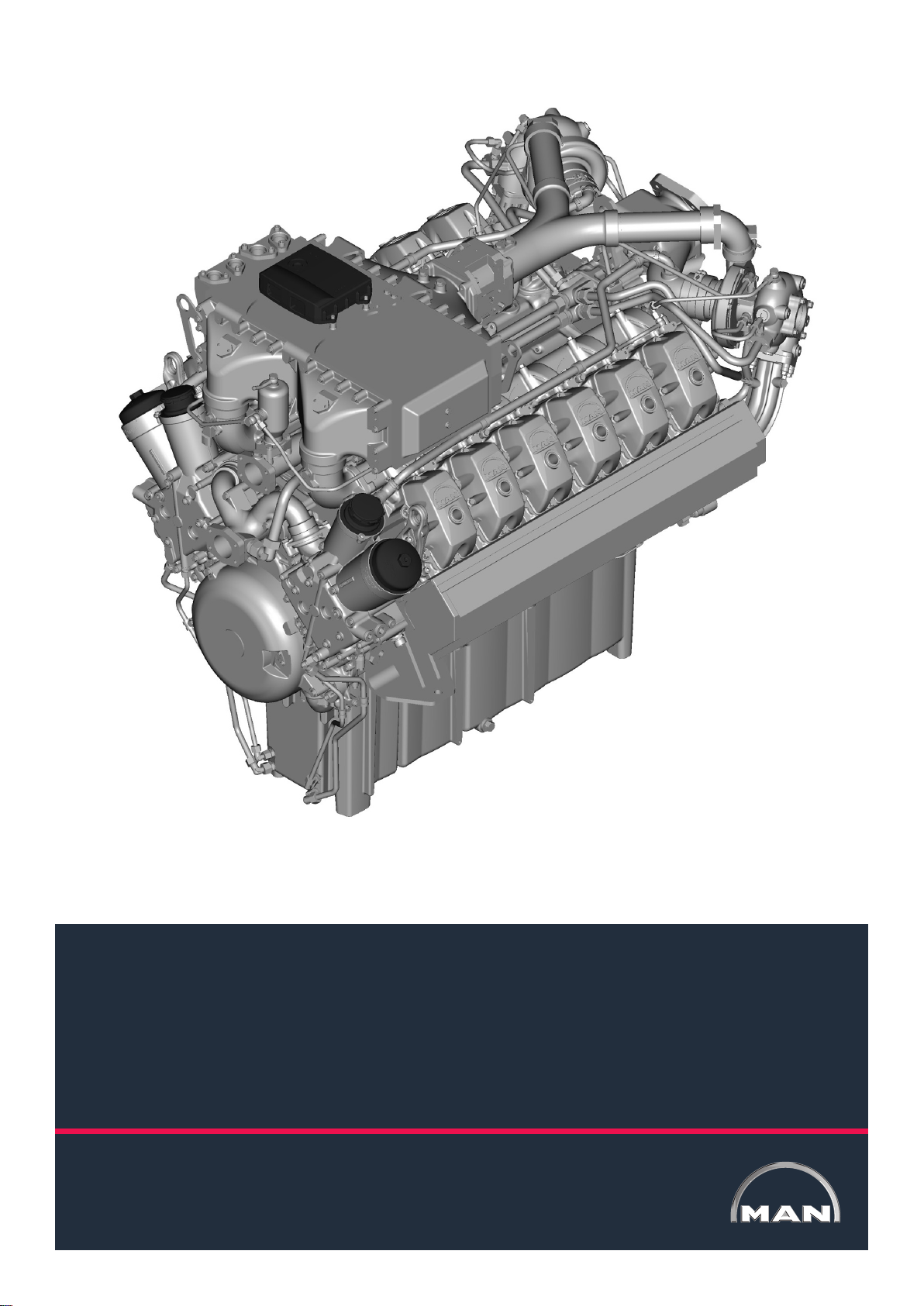
Operating Instruction
MAN Industrial Gas Engines
E3268 LE212/222 / E3262 LE202/212
MAN Engines
A Division of MAN Truck & Bus
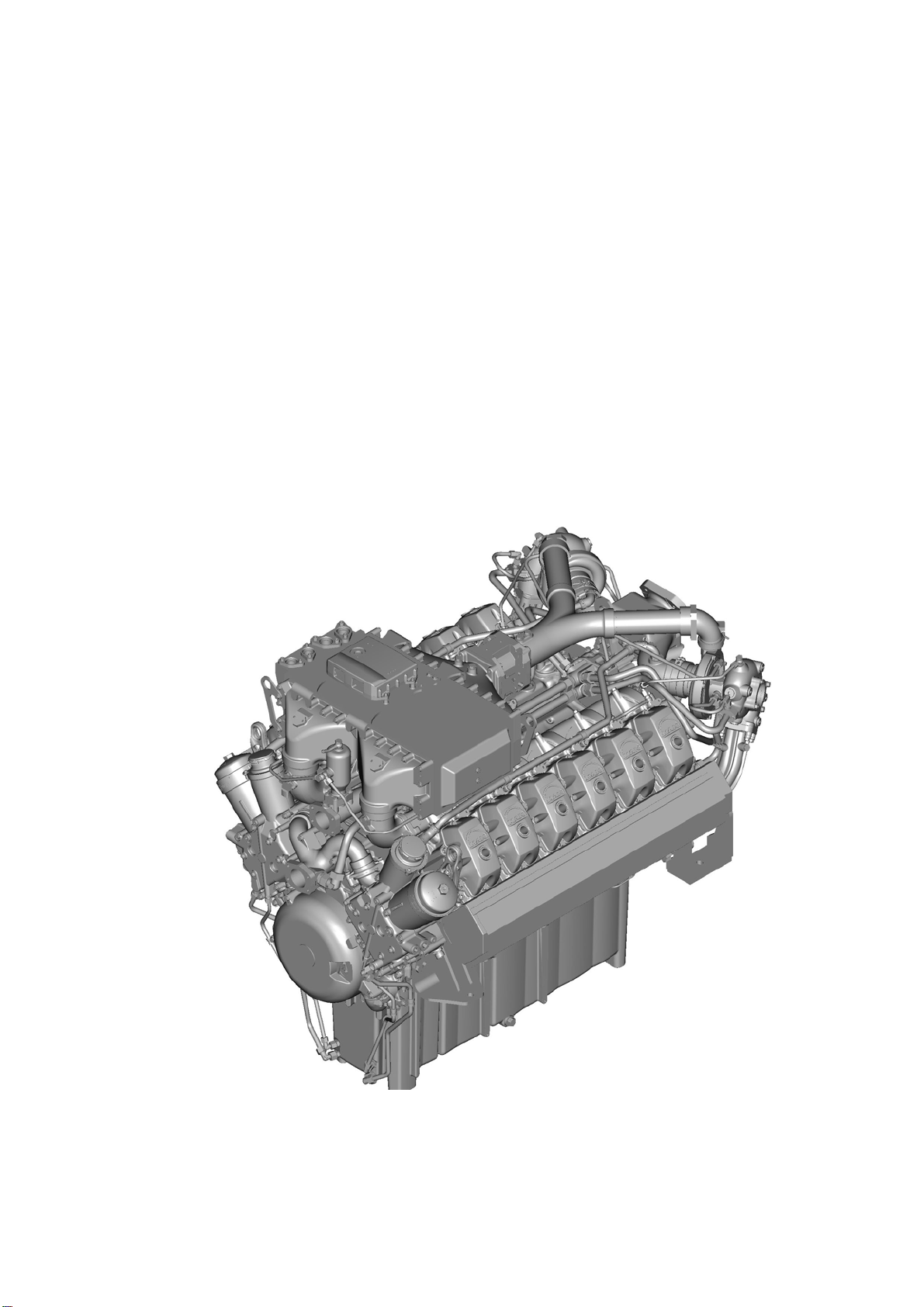
Page 2

Page 3
Operating Instruction
MAN Industrial Gas Engines
E3268 LE212, E3268 LE222
E3262 LE202, E3262 LE212
51.99587-8006
Version 05
Translation of the original instruction”
“
Page 4

Information and Copyright
Subject to change without notice.
Reprinting, copying or translation, even of extracts, is not allowed without written permission from MAN. All
rights under the copyright law are strictly reserved by MAN.
2016
MAN Truck & Bus AG
Vogelweiherstrasse 33
90441 Nürnberg
Germany
Tel.: +49 911 / 420-1745
Fax: +49 911 / 420-1932
email: Engine-Documentation@man.eu
internet: www.man-engines.com
Technical status: 03.2016
51.99587-8006
Carefully read these Operating Instructions before starting any work!
2
This is especially valid for the chapter on General Safety Instructions
and the safety instructions in each of the chapters.
Page 5

List of contents
Information and Copyright 2...............................................................
1 Foreword 7.........................................................................
1.1 Information about these instructions 7.............................................
1.1.1 Supplementary publications 7...............................................
1.1.2 Further publications 7......................................................
1.2 Symbol explanation 8...........................................................
1.3 Limitation of liability 9............................................................
1.4 Copyright protection 9...........................................................
1.5 Applicable documents 9.........................................................
1.6 Spare parts 10..................................................................
1.7 Disposal 10.....................................................................
1.8 Warranty provisions 11...........................................................
1.9 Product support 11...............................................................
2 General Safety Instructions 13........................................................
2.1 Intended use 13.................................................................
2.2 Content of the Installation and Operating Instructions 14..............................
2.3 Engine modifications and conversions 14...........................................
2.4 Operator's responsibility 14........................................................
2.5 Personnel requirements 15........................................................
2.5.1 Qualifications 15............................................................
2.5.2 Unauthorised personnel 15..................................................
2.5.3 Instruction 15..............................................................
2.6 Personal protective equipment 16..................................................
2.7 Particular dangers 17.............................................................
2.8 Safety equipment 20.............................................................
2.9 Response to danger and accidents 21..............................................
2.10 Signs 22........................................................................
2.11 Weight data E3268 LE212/LE222 23...............................................
2.12 Environmental protection 24.......................................................
3 Engine model plate 25................................................................
3.1 Explanation of Motor-Nr./Engine No. (engine identification number) 26..................
3.2 Explanation of model designation 26................................................
Carefully read these Operating Instructions before starting any work!
This is especially valid for the chapter on General Safety Instructions
and the safety instructions in each of the chapters.
3
Page 6

List of contents
4 Design and function 27...............................................................
4.1 Engine application fields 27.......................................................
4.2 Engine design and engine equipment 27............................................
4.3 Engine views E3262 LE202 29.....................................................
4.3.1 Front left view 29...........................................................
4.3.2 Front right view 30..........................................................
4.4 Engine views E3268 LE212 31.....................................................
4.4.1 Front left view 31...........................................................
4.4.2 Front right view 32..........................................................
5 Transport, packaging and storage 33..................................................
5.1 Requirements 33................................................................
5.2 Safety instructions 33............................................................
5.3 Transport inspection 35...........................................................
5.4 Transport 36....................................................................
5.5 Packaging 40....................................................................
5.6 Storage 40......................................................................
6 Installation and commissioning 41....................................................
6.1 Notes regarding installation and commissioning 41...................................
6.1.1 Requirements 41...........................................................
6.2 Safety instructions 41............................................................
6.3 Engine installation 42.............................................................
6.3.1 Interfaces between engine and plant 42.......................................
6.3.2 Installation Instructions 44...................................................
6.3.3 Installation drawing 44......................................................
6.3.4 Screw and bolt connections 44...............................................
6.4 Completion of the engine and assembly of the drive system 45.........................
6.4.1 Mounting an alternator on the flywheel housing 45..............................
6.4.2 Checking crankshaft axial clearance 46........................................
6.5 Connecting the cooling system 47..................................................
6.5.1 Connecting the engine cooling 47.............................................
6.6 Mounting the gas inlet 48.........................................................
6.7 Mounting the exhaust system 49...................................................
6.7.1 Exhaust gas outlet on engine 49..............................................
6.7.2 Connecting the exhaust system to the engine 50................................
6.8 Connecting the electrical system 51................................................
6.8.1 Starter 51.................................................................
6.9 Torques for screw and bolt connections to Works Standard M 3059 52..................
6.10 First commissioning 53...........................................................
6.11 Commissioning 54...............................................................
6.11.1 Gas system 54.............................................................
6.11.2 Adding coolant 55..........................................................
6.11.3 Filling Engine Oil 56.........................................................
Carefully read these Operating Instructions before starting any work!
4
This is especially valid for the chapter on General Safety Instructions
and the safety instructions in each of the chapters.
Page 7

List of contents
7 Operation and use 57.................................................................
7.1 Requirements 57................................................................
7.2 Safety instructions 57............................................................
7.3 Preparations prior to operation 58..................................................
7.3.1 Checking the gas quality, opening the gas supply 58............................
7.3.2 Checking the coolant 59.....................................................
7.3.3 Topping up the coolant 59...................................................
7.3.4 Check Engine Oil Level 60...................................................
7.3.5 Topping up the engine oil 61.................................................
7.4 Operation 62....................................................................
7.4.1 Starting 62.................................................................
7.4.2 Operation monitoring system 63..............................................
7.4.3 Emergency shutdown 63....................................................
7.4.4 Stopping 63................................................................
7.4.5 Data storage box 64........................................................
8 Maintenance and care 65..............................................................
8.1 Requirements 65................................................................
8.2 Safety instructions 65............................................................
8.3 Maintenance schedule 66.........................................................
8.3.1 Maintenance schedule for natural-gas operation 67.............................
8.3.2 Maintenance schedule for special gas operation 70.............................
8.4 Maintenance work 75.............................................................
8.4.1 Engine oil change 75........................................................
8.4.2 Changing the coolant 79.....................................................
9 Faults 81............................................................................
9.1 Requirements 81................................................................
9.2 Safety instructions 81............................................................
9.3 Troubleshooting chart 82..........................................................
10 Decommissioning and recommissioning 87............................................
10.1 Requirements 87................................................................
10.2 Safety instructions 87............................................................
10.3 Temporary decommissioning of an engine 88........................................
10.4 Recommissioning of decommissioned engines 89....................................
10.4.1 Commissioning of preserved engines to MAN Works Standard M 3069 89..........
10.4.2 Commissioning of non-preserved engines 89...................................
Carefully read these Operating Instructions before starting any work!
This is especially valid for the chapter on General Safety Instructions
and the safety instructions in each of the chapters.
5
Page 8

List of contents
11 Technical data 91....................................................................
11.1 Dimensions and weight 91........................................................
11.1.1 E3268 LE212/LE222 91.....................................................
11.1.2 E3262 LE202/LE212 91.....................................................
11.2 Installation location and space requirements 91......................................
11.3 Engine data 92..................................................................
11.3.1 E3268 LE212/LE222 92.....................................................
11.3.2 E3262 LE202/LE212 94.....................................................
12 Installation drawing 97...............................................................
12.1 Installation drawing E3268 LE212/LE222 97.........................................
12.2 Installation drawing E3262 LE202/LE212 103.........................................
13 Indices 111...........................................................................
13.1 Abbreviations 112.................................................................
13.2 List of keywords 113..............................................................
Carefully read these Operating Instructions before starting any work!
6
This is especially valid for the chapter on General Safety Instructions
and the safety instructions in each of the chapters.
Page 9

Foreword
1 Foreword
1.1 Information about these instructions
User tip
This provisional version of the instructions reflects the current development state of the engines.
These instructions therefore contain graphic representations of the MAN industrial gas engines on which
these instructions are based.
These instructions provide important information on handling engines. Safe working can only be assured if
all safety instructions and handling instructions are followed.
In addition to this, the local accident prevention regulations and general safety regulations applicable to the
engines' field of application must be followed.
Timely and proper maintenance and care of the engines according to the set maintenance intervals ensure
and maintain the operational safety and the reliable application of these engines.
Only use genuine MAN spare parts and accessories or ones that have been approved by MAN.
Only the genuine spare parts approved by us have been tested by us and therefore meet the requirements
for use of the engine.
A particular concern of MAN is to improve environmental protection.
This begins with the development and design of our engines. We make sure that no environmentally ha
zardous materials are used and, for example, that the emissions fulfil the highest requirements.
Economical operation helps to conserve our resources and our environment.
1.1.1 Supplementary publications
These instructions are supplemented by the following publications:
- Fuels, Lubricants and Coolants for MAN Industrial Gas Engines
Both publications are considered "parts of the product" and should always be kept in the immediate vicinity
of the engine for the personnel.
Carefully read the Installation and Operating Instructions before starting any work! This is especially valid
for the chapter on General Safety Instructions and the safety instructions in each of the chapters.
Failure to follow these instructions and any operating instructions provided by suppliers invalidates the war
ranty.
1.1.2 Further publications
The following publications supplement these instructions:
- Spare Parts Catalogue (included)
For the service personnel
- Repair Instructions
Carefully read these Operating Instructions before starting any work!
This is especially valid for the chapter on General Safety Instructions
and the safety instructions in each of the chapters.
7
Page 10

Foreword
1.2 Symbol explanation
Warnings
Warnings are indicated by symbols in these instructions. The warnings are preceded by signal
words which indicate the extent of the danger.
Always heed these warnings and act prudently to prevent accidents, injuries and property damage.
DANGER
Describes an immediately dangerous situation that will lead to serious injury or death if it is not avoided.
WARNING
Describes a possibly dangerous situation that can lead to serious injury or death if it is not avoided.
CAUTION
Describes a possibly dangerous situation that can lead to minor or moderate injury if it is not avoided.
NOTE
Describes a possibly dangerous situation that can lead to damage if it is not avoided.
Tips and Recommendations
User tip
Tips and recommendation as well as information for efficient and trouble-free operation.
ENVIRONMENTAL NOTE
Tips on how to deal with protection of the environment.
General Information
• This symbol indicates a list at the first level.
- This symbol indicates a list at the second level.
1. This symbol indicates a sequence of actions.
1
This symbol indicates a graphic item in the text.
Carefully read these Operating Instructions before starting any work!
8
This is especially valid for the chapter on General Safety Instructions
and the safety instructions in each of the chapters.
Page 11

Foreword
1.3 Limitation of liability
All of the information in these instructions have been prepared while taking into account the valid standards
and regulations, the state of the art, as well as our many years of experience and knowledge.
MAN is not liable for damages resulting from:
S Failure to follow these instructions
S Improper use
S Use of untrained personnel
S Customer conversions
S Technical modifications
S Use of non-approved spare parts and fuels, fluids and lubricants
The actual scope of delivery for special versions, additional ordering options or technical modifications may
deviate from what is described and illustrated in these instructions.
Valid are the commitments agreed upon in the delivery contract and the General Terms and Conditions of
MAN and the law applicable at the time of contracting arrangements.
1.4 Copyright protection
Treat the Installation and Operating Instructions confidentially. They are aimed solely at persons who deal
with the engine.
The instructions may not be passed to third parties without written approval from MAN.
User tip
The information, texts, drawings, illustrations and other depictions are all protected by copyright and are
subject to industrial property rights.
Any improper use is punishable by law.
1.5 Applicable documents
Supplier components are installed in the engine. Risk assessments have been carried out on these parts
by the suppliers.
The compliance of the design with the existing European and national legislation has been declared by the
respective suppliers of the components.
Carefully read these Operating Instructions before starting any work!
This is especially valid for the chapter on General Safety Instructions
and the safety instructions in each of the chapters.
9
Page 12

Foreword
1.6 Spare parts
Only use genuine MAN spare parts and accessories or ones that have been approved by MAN.
Only the spare replacement parts approved by us have been tested by us and therefore meet the require
ments for use of the engine.
Spare parts and accessories must either be MAN genuine parts or parts that have been specifically appro
ved by MAN. The reliability, safety and suitability of these parts have been established specifically for the
engines. We cannot assess and vouch for other non-MAN products, despite ongoing market observations.
WARNING
Risk of injury due to incorrect spare parts
Incorrect or faulty spare parts can lead to damage, malfunctions or total failures and interfere with
safety.
For this reason:
S Only use MAN genuine spare parts
User tip
Quote the engine type, engine number and order number in all enquiries and communications,
see page 25.
Order spare parts through authorised dealers or directly from MAN.
For address, see page 2.
1.7 Disposal
Dispose in accordance with national regulations.
If no return or disposal agreement has been made, recycle the disassembled components as follows:
S Sort metals before scrapping.
S Recycle the plastic parts.
S Dispose of all other parts according to their material composition.
10
Carefully read these Operating Instructions before starting any work!
This is especially valid for the chapter on General Safety Instructions
and the safety instructions in each of the chapters.
Page 13

Foreword
1.8 Warranty provisions
Valid are the commitments agreed upon in the delivery contract and the General Terms and Conditions of
MAN and the law applicable at the time of contracting arrangements.
Failure to follow these instructions and any operating instructions provided by suppliers invalidates the war
ranty.
The use of non-approved parts leads to the loss of warranty claims.
We recommend to use genuine parts even after the warranty period has expired. This will ensure the conti
nuous performance of the engine.
1.9 Product support
Our MAN product support is available for technical information.
User tip
Quote the engine type, engine number and order number in all enquiries and communications,
see page 25.
Information about contact persons can always be called up by telephone, fax, email or over the Internet.
For addresses see page 2.
Carefully read these Operating Instructions before starting any work!
This is especially valid for the chapter on General Safety Instructions
and the safety instructions in each of the chapters.
11
Page 14

Foreword
12
Carefully read these Operating Instructions before starting any work!
This is especially valid for the chapter on General Safety Instructions
and the safety instructions in each of the chapters.
Page 15

General Safety Instructions
2 General Safety Instructions
This chapter provides information on residual risks and hazards during proper use of the engine.
The generally valid safety instructions to be observed are listed here. They provide optimum protection for
personnel and for the safe and smooth operation of the engine.
In the following, specific, action and situation-related safety information is placed before the corresponding
step, or in the chapter described.
Failure to observe the Operating Instructions and Safety Instructions in this document can result in signifi
cant hazards.
2.1 Intended use
The engine is built exclusively to drive generators or for the coupling of heat exchangers within the limits of
technical data.
Any other use is considered as "non-intended".
MAN is not liable for any damage resulting from non-intended use. The risk is entirely borne by the opera
tor.
Intended use also includes compliance with the country-specific, local environmental regulations.
This in particular concerns the compliance with the applicable legal exhaust emission limits.
Furthermore, the engine operating parameters according to the technical data sheets currently in effect
must also be adhered to.
The mixture generating and control system, as well as - if needed - the exhaust aftertreatment system must
be prepared by the manufacturer of the complete machine to meet these criteria.
Intended use also includes compliance with the prescribed operating, maintenance and repair work.
The engine may only be used, maintained and repaired by persons who are familiar with the engine and
have been informed of the hazards.
Unauthorised modifications to the engine shall void any liability for any resulting property damage and per
sonal injury.
Similarly, tampering with the control system can affect engine performance and emission characteristics.
Compliance with statutory environmental protection requirements is therefore no longer guaranteed.
DANGER
Danger due to non-intended use
Any use that exceeds the intended use and/or any different use of the engine can lead to dangerous
situations which will invalidate the operating permit.
For this reason:
S Use the engine for its intended purpose only.
S Use the engine outside of hazardous areas where there is a risk of explosion.
S Use the engine with an overspeed limiting device installed.
User tip
Observe the following information when operating the engine:
S The safety instructions in these Operating Instructions and the suppliers' instructions.
S The “Technical data" section in these instructions and the suppliers' instructions.
S Country-specific regulations.
Carefully read these Operating Instructions before starting any work!
This is especially valid for the chapter on General Safety Instructions
and the safety instructions in each of the chapters.
13
Page 16

General Safety Instructions
2.2 Content of the Installation and Operating Instructions
Any person who is instructed to perform work on or with the engine, must have read and understood these
Operating Instructions before starting any work. This also applies if the person has worked with such an
engine or a similar engine, or has already been trained by MAN.
Familiarity with these instructions is therefore essential.
2.3 Engine modifications and conversions
In order to avoid hazards and to ensure optimum performance, no modifications or conversions to the en
gine may be made which are not expressly approved by MAN.
If changes are made without the written consent of MAN, the guarantee or warranty obligation for MAN is
no longer valid for damage and defects which are based on these unauthorised changes. Furthermore
MAN assumes no liability for any damage caused as a result of unauthorised changes.
2.4 Operator's responsibility
The engine operator is subject to the statutory requirements for workplace safety.
In addition to the Safety Instructions in these Operating Instructions, the safety regulations, accident pre
vention regulations and environmental protection regulations valid for the application area of this engine
must also be observed.
In particular:
S The operator must be knowledgeable about the valid occupational health and safety regulations and be
able to assess, in a risk analysis, the dangers that are present in the specific working conditions at the
operating site of the engine. He must then implement these safety regulations in the form of operating
instructions for the operation of the engine.
S During the entire period of operation of the engine the operator must check whether the operating in
structions he created meet the most current standards and regulations and revise them if necessary.
S The operator must clearly define and regulate the responsibilities for installation, operation, maintenance
and cleaning of the product.
S The operator must ensure that all staff who deal with the engine have read and understood the Opera
ting Instructions.
In addition, the operator must periodically train the staff and inform them about hazards.
S The operator must provide the personnel with the necessary protective equipment.
S The operator must limit access to the operating room.
S The operator must ensure proper ventilation of the operating room.
S These operating instructions must be kept in the immediate vicinity of the engine and be readily accessi
ble at any time to those persons working on and with the engine.
The operator is responsible for ensuring that the engine is always operated in perfect working condition and
working order.
In particular:
S Perform maintenance work as described in these instructions in full and at the
specified intervals or have it performed by a MAN Service workshop/authorised MAN partner.
S The operator must have all safety equipment checked regularly for function and integrity.
S The instructions must be followed in full and without restrictions!
14
Carefully read these Operating Instructions before starting any work!
This is especially valid for the chapter on General Safety Instructions
and the safety instructions in each of the chapters.
Page 17

General Safety Instructions
2.5 Personnel requirements
2.5.1 Qualifications
WARNING
Risk of injury if personnel is not sufficiently qualified
Improper handling can result in significant personal injury and property damage.
For this reason:
S Specific activities must only be performed by those persons who are named in the respective chapters
in these Operating Instructions.
The following qualifications are specified for various areas of activity in the instructions:
S Instructed Persons
Have been instructed in a briefing about the possible dangers of improper handling in their tasks.
S Qualified Personnel
Due to their technical training, knowledge and experience and knowledge of the relevant regulations
they can properly perform the tasks assigned to them.
S Electric Specialist
Is capable of performing work on electrical systems due to his/her technical education/training, know
ledge and experience as well as knowledge of the respective standards and regulations and can recog
nise and avoid any possible dangers.
The electric specialist is trained for the specific operating site in which he/she works and knows the rele
vant standards and regulations.
Only those people who can perform their work reliably should be considered as authorised personnel. Indi
viduals whose responsiveness is influenced, for example, by alcohol or drugs, are not permitted.
S When selecting personnel, observe the regulations regarding age and profession valid at the operating
site.
2.5.2 Unauthorised personnel
WARNING
Danger to unauthorised personnel
Unauthorised persons who do not fulfil the requirements described here do not realise the dangers that
exist in the working area.
For this reason:
S Keep unauthorised persons out of the working area.
S In case of doubt, address the person and remove him/her from the working area if necessary.
S Interrupt the work until all unauthorised persons are out of the working area.
2.5.3 Instruction
Personnel must be instructed on regular basis and this should be documented in a log to keep better track
of who and when.
Carefully read these Operating Instructions before starting any work!
This is especially valid for the chapter on General Safety Instructions
and the safety instructions in each of the chapters.
15
Page 18

General Safety Instructions
2.6 Personal protective equipment
Wearing personal protective equipment is necessary to minimise the health risks when working.
S The required personal protective equipment for the relevant job must always be worn while working.
S All signs pertaining to personal protective equipment in the working area must be followed.
Protective Clothing
Close-fitting clothing with low initial tear strength, with narrow sleeves and with no pro
truding parts. It is used primarily to protect against injury, weather and dirt.
No rings, bracelets, necklaces and other jewellery are to be worn while working.
Protective Helmet
To protect against falling and flying parts.
Safety Shoes
To protect against heavy falling parts and slipping on slippery surfaces.
Safety Gloves
To protect the hands from friction, scraping, punctures or deep injuries and to protect
from hot or caustic parts or fluids
To be worn when performing specific types of work
When performing certain types of work, special protective equipment is required. This will be specifically
mentioned in the relevant chapters.
Safety Glasses
To protect the eyes against flying parts and sprayed fluids.
Hearing Protection
To protect the ears from damage by loud noises.
16
Carefully read these Operating Instructions before starting any work!
This is especially valid for the chapter on General Safety Instructions
and the safety instructions in each of the chapters.
Page 19
General Safety Instructions
2.7 Particular dangers
The following section describes residual risks which have been identified.
S Observe the safety instructions listed here and the warnings in the other chapters of these instructions
in order to reduce health hazards and avoid dangerous situations.
Electrical Current
DANGER
Danger to life due to electrical voltage
Touching live parts endangers life.
Damaged insulation of components endanger life.
For this reason:
S If the insulation is damaged, immediately switch off the power supply and get the insulation repaired.
S Any work performed on the electrical system may only be made by a qualified electrician.
S When working on the electrical system the power supply must be switched off and then properly
checked to ensure no electrical current is present.
S Before starting any maintenance, cleaning or repair work the power supply must be switched off and
secured from being accidentally switched back on.
S Do not bridge or bypass any fuses. When replacing fuses, ensure to use the correct amperage.
S Keep moisture clear of parts conducting electrical current. This could cause a short-circuit.
Moving Parts
WARNING
Risk of injury due to moving parts
Rotating and/or linear-moving components can cause injuries.
For this reason:
S Do not touch or handle moving parts during operation.
S Do not open the covers during operation.
S Only perform checking and maintenance jobs when the engine is at a standstill.
S Observe the run-on time: before opening any covers ensure that no parts are still moving.
S Wear close-fitting clothing in the hazard area.
Flying components in the event of sudden engine damage
WARNING
Risk of injury due to running engines
In the event of engine damage, components can fly through the engine room at high speed and injure
people in the immediate vicinity.
For this reason:
S Do not remain in the engine room when the engine is running.
Carefully read these Operating Instructions before starting any work!
This is especially valid for the chapter on General Safety Instructions
and the safety instructions in each of the chapters.
17
Page 20

General Safety Instructions
Exhaust gases
WARNING
Health risk due to leaking exhaust system
Exhaust gases can damage health.
For this reason:
S Immediately stop and repair machines with leaking exhaust systems.
S Ensure sufficient ventilation.
Highly Flammable Substances - Gaseous Fuels, Oils and Grease
WARNING
Risk of injury due to highly inflammable materials
Highly inflammable materials, liquids or gases catch fire easily.
For this reason:
S Smoking, naked flames and sources of ignition are prohibited in the danger zone and immediate sur
roundings.
S Keep fire extinguishers at hand.
S Immediately report any suspicious substances, fluids or gases to the person in charge.
S Repair any leaks.
S In the case of fire, immediately stop working. Leave hazard area until the danger is over.
Coolants - Antifreeze, Anticorrosion Agents
WARNING
Risk of injury caused by coolants that are hazardous to health
Coolant contains substances that are hazardous to health.
For this reason:
S Observe the safety sheets from the manufacturer.
S Always wear protective clothing, chemical-resistant protective gloves and safety glasses.
S Avoid spilling or spraying these substances.
Hot Fluids and Lubricants
WARNING
Risk of burns due to hot fuels, lubricants and coolants
Fuels, lubricants and coolants get hot during operation and cause burns if touched.
For this reason:
S Before handling any fluids and lubricants, check whether they are hot. If necessary, let them cool
down first.
18
Carefully read these Operating Instructions before starting any work!
This is especially valid for the chapter on General Safety Instructions
and the safety instructions in each of the chapters.
Page 21

General Safety Instructions
Hot Surfaces
CAUTION
Risk of burns due to hot surfaces
Touching hot components causes burns.
For this reason:
S When performing any work in the vicinity of hot components always wear protective clothing and
protective gloves.
S Before starting any work ensure that all components have cooled down to ambient temperature.
Noise
WARNING
Hearing damage due to noise
The noise level in the working area can cause serious hearing damage.
For this reason:
S Always wear hearing protection when working.
S Do not unnecessarily remain in the hazard area. Leave hazard area when work is finished.
Sharp Edges and Corners
CAUTION
Risk of injury on edges and corners
Sharp edges and corners can cause skin grazes and cuts.
For this reason:
S Always work carefully and with caution in the vicinity of sharp edges and corners.
S In cases of doubt, wear protective gloves.
Dirt and Objects
CAUTION
Risk of tripping due to dirt and discarded objects
Dirt and discarded objects represent a tripping and slipping hazard and can cause serious injuries.
For this reason:
S Always keep the work area clean.
S Remove any objects that are no longer necessary.
S Mark areas where there is a danger of tripping with yellow and black striped tape.
Carefully read these Operating Instructions before starting any work!
This is especially valid for the chapter on General Safety Instructions
and the safety instructions in each of the chapters.
19
Page 22

General Safety Instructions
2.8 Safety equipment
The operator must have the following safety equipment in place:
Before the engine is placed into operation, install the emergency-off equipment and connect it into the
safety chain of the system.
Connect the emergency-off equipment so that dangerous situations to people and property are avoided in
case the its power supply is interrupted or is turned back on after an interruption.
The emergency-off equipment must always be freely accessible.
WARNING
Danger to life due to non-functioning safety equipment
For this reason:
S Before commencing work, check that all safety equipment is functioning and correctly installed.
S Before starting the engine, check that all safety equipment is functioning and correctly installed.
20
Carefully read these Operating Instructions before starting any work!
This is especially valid for the chapter on General Safety Instructions
and the safety instructions in each of the chapters.
Page 23

General Safety Instructions
2.9 Response to danger and accidents
Preventative Measures
S Always be prepared for an accident!
S Keep first aid equipment (first aid kit, blankets, etc.) and fire extinguishers at hand.
S Regularly check first-aid equipment and fire extinguishers for completeness and correct functioning.
S Familiarise the personnel with the emergency, first aid and rescue equipment.
S Instruct the personnel on safety on a regular basis.
S Always keep access lanes for rescue vehicles free of any obstructions.
In the case of an accident: Act accordingly
S Remain calm.
S Immediately shut down engine using the emergency-off button.
S Start first-aid measures.
S Alert rescue services and/or fire department.
S Move people out of the danger zone.
S Clear access lanes for rescue vehicles.
S Inform the person in charge.
CAUTION
Accidents despite preventative measures
Should an accident occur despite all preventative measures, e.g. due to one of the reasons listed below,
call a doctor immediately:
S Contact with caustic acids.
S Penetration of fuel into the skin.
S Scalding by hot oil or coolant.
S Antifreeze sprayed into the eyes, etc..
Carefully read these Operating Instructions before starting any work!
This is especially valid for the chapter on General Safety Instructions
and the safety instructions in each of the chapters.
21
Page 24

General Safety Instructions
2.10 Signs
WARNING
Risk of injury due to illegible symbols
Labels and symbols get dirty over time, rendering them illegible.
For this reason:
S Always keep the safety, warning and operational signs in good legible condition.
S Clean or replace illegible safety, warning and operational signs.
The following symbols should be installed in the immediate vicinity of the hazard area.
Access forbidden
Areas displaying this sign must not be entered.
Electric Voltage
Spaces marked with this symbol may only be accessed by qualified electricians.
Unauthorised persons may not enter these spaces.
Hot Surfaces
Hot surfaces such as hot engines and hot fluids may not always be recognisable. Do not
touch these surfaces without protective gloves.
Danger to life due to suspended loads
During lifting operations, loads can swing out and fall down. This can cause serious in
jury and even death.
Risk of injury
Failure to follow the instructions poses a risk of injury.
22
Carefully read these Operating Instructions before starting any work!
This is especially valid for the chapter on General Safety Instructions
and the safety instructions in each of the chapters.
Page 25

General Safety Instructions
2.11 Weight data E3268 LE212/LE222
Ensure that suitable lifting gear is used for handling the engine and the engine parts listed in the table.
Part Weight (kg)
Oil pan 95l 27
Crankcase 459
Crankshaft 131
Flywheel housing 30
Flywheel 66
Exhaust turbocharger 1500 rpm 38
Charge mixture cooler E3268 88
Engine carriage 107
Carefully read these Operating Instructions before starting any work!
This is especially valid for the chapter on General Safety Instructions
and the safety instructions in each of the chapters.
23
Page 26

General Safety Instructions
2.12 Environmental protection
ENVIRONMENTAL NOTE
Risk of environmental pollution due to incorrect handling of service products
Serious environmental damage can result.
For this reason:
S Follow the safety instructions.
S Take suitable measures immediately if environmentally hazardous substances escape into the envi
ronment.
S Inform the relevant local authorities of the damage.
The following environmentally hazardous substances are used:
Lubricants
Lubricants such as grease and oils contain poisons and environmentally hazardous substances. They must
not be allowed to be released into the environment. Disposal must be performed by a qualified disposal
company.
Coolants
Coolants can contain poisons and environmentally hazardous substances. They must not be allowed to be
released into the environment. Disposal must be performed by a qualified disposal company.
24
Carefully read these Operating Instructions before starting any work!
This is especially valid for the chapter on General Safety Instructions
and the safety instructions in each of the chapters.
Page 27
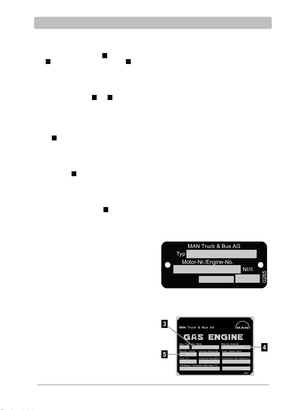
3 Engine model plate
Always quote the engine type 3, engine num
4
ber
and factory number/order number 5 in all
enquiries and communications.
Before the engine is first commissioned, you
should therefore check the relevant data on the
engine model plates and enter it below.
1
The engine model plates
the crankcase.
and 2 are attached to
Engine Model Plate
Model
......................................................................
Engine number
......................................................................
Factory number/order number
......................................................................
3
4
5
Carefully read these Operating Instructions before starting any work!
This is especially valid for the chapter on General Safety Instructions
and the safety instructions in each of the chapters.
25
Page 28

Engine Model Plate
3.1 Explanation of Motor-Nr./Engine No. (engine identification number)
Class identifier (assignment) 1 2 3 4
Motor-Nr./Engine No. XXX XXXX XXX XXXX
1 Model number after model code
2 Day of assembly (determined internally at factory)
3 Assembly sequence (consecutive number on day of assembly)
4 Production- and equipment-specific data
3.2 Explanation of model designation
Model designation Explanation Example
E Fuel type Natural gas/biogas
32 Figure + 100 132 mm bore
6 Stroke figure (rounded) 157 mm stroke
8 / 2 Number of cylinders 8, 12 cylinders
L Charging with charging and
charge mixture cooling
E Engine installation Installation engine
202/212/222 Model designation identification Development number
26
Carefully read these Operating Instructions before starting any work!
This is especially valid for the chapter on General Safety Instructions
and the safety instructions in each of the chapters.
Page 29

Design and Function
4 Design and function
4.1 Engine application fields
The 8- and 12-cylinder engines described here are liquid-cooled 4-stroke petrol engines with exhaust gas
turbocharger and mixture cooling.
4.2 Engine design and engine equipment
Engines E3268 LE212, E3268LE222 and E3262 LE202, E3262 LE212 are 8- or 12-cylinder gas engines
with turbocharger and mixture cooling.
Split crankcase, wet cylinder liners made of highly wear-resistant special centrifugal casting, aluminium
piston with cooling duct for piston cooling. Single cylinder heads with shrink-fitted valve seats and pressedin valve guides. 4 valves per cylinder. Valve control via central camshaft, roller tappets, tappet push rods
and rocker arms (OHV).
Charge mixture system
The charge mixture system consists of the charge mixture cooler, the charge mixture manifolds, the throttle
valve and the air distributor pipes.
Gas supply line
The gas supply line - consisting of ball cock, gas filter, solenoid valves, gas pressure regulator, gas mixer
and air filter - is not supplied by MAN.
Engine Lubrication
Force-feed lubrication with two lubrication oil pumps for crankshaft, conrod and camshaft bearings as well
as piston pin sockets, roller tappet and rocker arm.
Oil filtration through oil modules with integrated oil cooler and crankcase breather in main flow. Auxiliary
units such as turbocharger are connected to the engine lubrication oil circuit.
Intake and Exhaust System
Dry exhaust pipes.
For E3268, one exhaust turbocharger; for E3262, two exhaust turbochargers.
The exhaust turbochargers are lubricated via the engine's main flow oil circuit.
The intake air flows through the air filter to the gas mixer and then to the turbocharger(s). The now precom
pressed air/gas mixtures are supplied to the engine after mixture cooling.
Carefully read these Operating Instructions before starting any work!
This is especially valid for the chapter on General Safety Instructions
and the safety instructions in each of the chapters.
27
Page 30

Design and Function
Flywheel housing and flywheel
The flywheel housing as a connection to SAE1.
Different flywheel versions can be supplied, depending on the type of application.
Starter
The electric starter is of two-pin, insulated design. The starter can be mounted on the left or right of the en
gine.
28
Carefully read these Operating Instructions before starting any work!
This is especially valid for the chapter on General Safety Instructions
and the safety instructions in each of the chapters.
Page 31

4.3 Engine views E3262 LE202
4.3.1 Front left view
Design and Function
1 Vent housing for coolant
2
Data acquisition
3
Throttle valve
4
Exhaust turbocharger
5
Oil pan
Carefully read these Operating Instructions before starting any work!
This is especially valid for the chapter on General Safety Instructions
and the safety instructions in each of the chapters.
6 Oil drain plug
7
Protective cover for crankshaft
and vibration damper
8
Oil filter
9
Oil separator
29
Page 32

Design and Function
4.3.2 Front right view
1
Intake manifold
2
Charge mixture cooler
3
Coolant outlet
4
Coolant inlet
5
Oil drain plug
6
Heat protection cover
7
Oil filler neck
User tip
The gas supply line - consisting of ball cock, gas filter, solenoid valves, gas pressure regulator, gas mi
xer and air filter - is not supplied by MAN.
30
Carefully read these Operating Instructions before starting any work!
This is especially valid for the chapter on General Safety Instructions
and the safety instructions in each of the chapters.
Page 33

4.4 Engine views E3268 LE212
4.4.1 Front left view
Design and Function
1
Oil separator
2
Vent housing for coolant
3
Data acquisition
4
Throttle valve
5
Exhaust turbocharger
Carefully read these Operating Instructions before starting any work!
This is especially valid for the chapter on General Safety Instructions
and the safety instructions in each of the chapters.
6
Oil pan
7
Oil drain plug
8
Protective cover for crankshaft
and vibration damper
9
Oil filter
31
Page 34

Design and Function
4.4.2 Front right view
1
Intake manifold
2
Charge mixture cooler
3
Coolant outlet
4
Coolant inlet
5
Oil drain plug
6
Oil dipstick
7
Oil filler neck
User tip
The gas supply line - consisting of ball cock, gas filter, solenoid valves, gas pressure regulator, gas mi
xer and air filter - is not supplied by MAN.
32
Carefully read these Operating Instructions before starting any work!
This is especially valid for the chapter on General Safety Instructions
and the safety instructions in each of the chapters.
Page 35

Transport, Packaging and Storage
5 Transport, packaging and storage
It is absolutely necessary to observe the “Installation Instructions” for the installation and commissioning of
a new or reconditioned engine.
User tip
Installation and commissioning is only to be performed by the employees of the manufacturer of the
entire system or by manufacturer authorised personnel.
5.1 Requirements
Before starting any work read and observe the General Safety Instructions and the safety information in
this chapter.
Strictly observe these instructions and act prudently to avoid accidents, personal injury and property
damage.
Personal Protective Equipment
The following protective equipment must be worn:
S Protective Clothing
S Protective Helmet
S Safety Shoes
S Safety Gloves
5.2 Safety instructions
Heavy Suspended Loads
WARNING
Danger to life due to suspended loads
During lifting, loads can swing out and drop.
For this reason:
S Do not stand under or remain in the swivel range of the suspended load.
S Only move the load under supervision.
S Only use approved lifting equipment and accessories with sufficient load capacity.
S Never use torn or scuffed lifting equipment such as ropes or straps.
S Do not let lifting equipment such as rope or straps come into contact with sharp edges and corners
and do not twist or knot them.
S Before leaving the work area, lower load to ground.
Carefully read these Operating Instructions before starting any work!
This is especially valid for the chapter on General Safety Instructions
and the safety instructions in each of the chapters.
33
Page 36

Transport, Packaging and Storage
Off-Centre Point of Gravity
WARNING
Danger to life due to incorrect handling of transported item
Transported item can swing out, tilt and/or drop.
For this reason:
S Use the crane hook lugs solely for transporting the engine without attachments (without alternator).
S Observe the information and markings on the package concerning centre of gravity.
S When transporting with a crane, the hook must be placed so that it is directly above the package's
centre of gravity.
S Carefully raise the package and observe its movement. If necessary, change the position of the lifting
equipment.
S Handle transported items carefully and note the symbols and instructions on the packaging.
S Use lifting gear. Diagonal pull not permitted.
Swingout of Packages being Transported
WARNING
Risk of injury due to transported item swinging out
Transported item can cause injury and damage
For this reason:
S Ensure that during the transport of packages, no persons, objects or obstacles are in the swivel range
of the packages being transported.
Unauthorised Transport
NOTE
Risk of damage due to untrained personnel
For this reason:
S Only trained personnel are allowed to unload the transported items.
S Unauthorised transport or attachment/removal of transport aids is not permitted.
S No unauthorised removal of packaging permitted.
Improper Transport
NOTE
Damage due to improper transport
Improper transport can cause packages to fall or tip over. This could cause considerable property
damage.
For this reason:
S Carefully handle the packages when unloading during delivery and when transporting them within the
company. Observe the symbols and instructions on the packages.
S Only use the prescribed lifting points.
34
Carefully read these Operating Instructions before starting any work!
This is especially valid for the chapter on General Safety Instructions
and the safety instructions in each of the chapters.
Page 37

Transport, Packaging and Storage
5.3 Transport inspection
Check the delivery for missing items and for damage from transport.
If external signs of transport damage are apparent:
S Do not accept delivery or only accept under written protest.
S List scope of damage on the transport documents or on the transportation company's packaging slip.
S Initiate a claims process.
User tip
Make sure to claim each damage case as soon as it is discovered. Damage claims can only be claimed
within the applicable time limits.
During work on the engine, the engine 1 must not
be accessed!
Carefully read these Operating Instructions before starting any work!
This is especially valid for the chapter on General Safety Instructions
and the safety instructions in each of the chapters.
35
Page 38

Transport, Packaging and Storage
5.4 Transport
DANGER
Falling loads (weight 2000kg!) can lead to serious accidents
For this reason:
S Use sufficiently dimensioned crane lifting gear for lifting an engine!
Ropes and chains must exert vertical tension (tolerance 5_) on the crane hooks.
Crane lifting gear, ropes and chains must be in perfect condition.
WARNING
Danger to life due to incorrect handling of transported item
Transported item can swing out, tilt and/or drop.
For this reason:
S Use the crane hook lugs solely for transporting the engine with gearbox.
S Observe the information and markings on the package concerning centre of gravity.
S When transporting with a crane, the hook must be placed so that it is directly above the package's
centre of gravity.
S Carefully raise the package and observe its movement. If necessary, change the position of the lifting
equipment.
S Handle transported items carefully and note the symbols and instructions on the packaging.
S Use lifting gear. Diagonal pull not permitted.
36
Carefully read these Operating Instructions before starting any work!
This is especially valid for the chapter on General Safety Instructions
and the safety instructions in each of the chapters.
Page 39

Attachment points E3262 LE202, E3262 LE212
Transport, Packaging and Storage
For lifting the engine, 3 crane hook lugs 1 are attached to the engine.
Carefully read these Operating Instructions before starting any work!
This is especially valid for the chapter on General Safety Instructions
and the safety instructions in each of the chapters.
37
Page 40

Transport, Packaging and Storage
Attachment points E3268 LE212, E3268 LE222
For lifting the engine, 3 crane hook lugs 1 are attached to the engine.
Carefully read these Operating Instructions before starting any work!
38
This is especially valid for the chapter on General Safety Instructions
and the safety instructions in each of the chapters.
Page 41

Transport, Packaging and Storage
Transport with Crane
The engine can be transported with a crane under the following conditions.
S The crane and the lifting equipment must be designed for the weight of the engine.
S Ropes and chains must not exert diagonal pull on the crane hooks.
S The operator must be qualified for operating the crane.
1. Attach the ropes, straps or multipoint lifting equipment according to the picture.
2. Ensure that the package is hanging straight or compensate for the off-centre point of gravity.
3. Start the transport.
Transport with Forklift
The engine can be transported with a forklift under the following conditions.
S The forklift must be designed for the weight of the engine.
S The engine must be securely mounted on the pallet.
S The pallet must not be damaged.
S The forklift operator must be qualified and authorised to operate the forklift.
1. Insert the fork of the forklift between or under the pallet's struts.
2. The fork must be inserted into the pallet until it protrudes from the other side.
3. Ensure that the pallet cannot tip over if the centre of gravity of off-centre.
4, Lift the pallet and transport it to the desired location.
Carefully read these Operating Instructions before starting any work!
This is especially valid for the chapter on General Safety Instructions
and the safety instructions in each of the chapters.
39
Page 42

Transport, Packaging and Storage
5.5 Packaging
Packaging
The individual packages are packed in accordance with the expected conditions of transport.
The purpose of the packaging is to protect the components from transport damage, corrosion and other
damage. For this reason do not unpack components until shortly before they are to be assembled.
Handling Packing Material
Dispose of packing material according to the valid local and statutory regulations.
ENVIRONMENTAL NOTE
Incorrect disposal of packaging materials poses an environmental hazard
• Dispose of packing materials in an environmentally friendly manner.
• Observe the valid local regulations. If necessary, contact a professional disposal company.
5.6 Storage
Storage of packages
Store packages under the following conditions:
S Do not store in the open.
S Store in a dry and dust-free environment.
S Do not expose to damaging chemicals.
S Protect from sunlight.
S Avoid any physical shocks.
S Storage temperature: 15 to 35 °C.
S Relative air humidity: max. 60%.
S If stored for more than 3 months, regularly check the condition of the packaging. If necessary, renew or
replace the preservation.
User tip
Some of the packages may have information printed on them regarding their proper storage. Please
observe this information.
40
Carefully read these Operating Instructions before starting any work!
This is especially valid for the chapter on General Safety Instructions
and the safety instructions in each of the chapters.
Page 43

Installation and Commissioning
6 Installation and commissioning
6.1 Notes regarding installation and commissioning
6.1.1 Requirements
Before starting any work read and observe the General Safety Instructions and the safety information in
this chapter.
Strictly observe these instructions and act prudently to avoid accidents, personal injury and property
damage.
Personal Protective Equipment
The following protective equipment must be worn:
S Protective Clothing
S Safety Shoes
S Safety Gloves
6.2 Safety instructions
Personnel
S The installation and commissioning may only be performed by MAN employees or by MAN-trained quali
fied personnel.
WARNING
Danger caused by faulty installation and commissioning!
Installation and commissioning require trained qualified personnel with sufficient experience. Faulty in
stallation can cause life threatening situations and considerable property damage.
For this reason:
S Installation and commissioning may only be performed by expert personnel trained by MAN.
Ground Rules
WARNING
Risk of injury due to improper installation and commissioning
Improper installation and commissioning can cause serious personal injury or considerable property
damage.
For this reason:
S Ensure adequate work space before starting any work.
S Be careful when working with exposed parts with sharp edges.
S Make sure work space is kept clean and orderly!
S Install components in a correct manner.
S Observe the prescribed tightening torques.
S Secure components so that they do not fall or tip over.
S Before commissioning the engine, carefully read the Operating Instructions and familiarise yourself with
the “critical” subjects.
S It is absolutely necessary to observe the “Assembly Instructions” for the installation and commissioning
of a new or reconditioned engine.
S For safety reasons we recommend placing an off limits sign on the door to the engine room and to in
struct the operating personnel that they are responsible for the safety of people who enter the engine
room.
Carefully read these Operating Instructions before starting any work!
This is especially valid for the chapter on General Safety Instructions
and the safety instructions in each of the chapters.
41
Page 44

Installation and Commissioning
6.3 Engine installation
6.3.1 Interfaces between engine and plant
1
Coolant connections on charge mixture cooler
2
Exhaust turbocharger
3
Intake manifold
4
Exhaust turbocharger
2
and 4 Mount exhaust system, see page 49
3
Mount gas inlet, see page 48
6
and 7 Connect cooling system, see page 47
Carefully read these Operating Instructions before starting any work!
42
This is especially valid for the chapter on General Safety Instructions
5
Engine mounting
6
Coolant inlet
7
Coolant outlet
and the safety instructions in each of the chapters.
Page 45

Installation and Commissioning
1 Exhaust turbocharger
2
Exhaust turbocharger
When installing the engine, perform the following assembly work on the interfaces between engine and
plant:
1
and 2 Mount exhaust system, see Installation Instructions
3
Mount alternator, see page 45
4
Connect gas inlet, see page 48
3 Flywheel
4
Gas inlet
Carefully read these Operating Instructions before starting any work!
This is especially valid for the chapter on General Safety Instructions
and the safety instructions in each of the chapters.
43
Page 46

Installation and Commissioning
6.3.2 Installation Instructions
Only general engine installation instructions can be given in this chapter.
More detailed information can be found in the “Installation Instructions for MAN Industrial Gas Engines”.
These instructions can be obtained from MAN, see page 2 for contact address.
6.3.3 Installation drawing
The installation drawing provides information about the type of connections and the connection dimensions.
Depending on the scope of delivery, wiring diagrams, layout diagrams for the resilient engine mounts etc.
may be required. These can be obtained from MAN, see page 2 for contact address.
NOTE
Engine installation is based on the installation instructions and the installation drawing.
For this reason:
S Observe these sources of information for each of the assembly jobs listed hereafter.
6.3.4 Screw and bolt connections
Always tighten screw and bolt connections using a torque wrench.
The assembly tightening torques for all common screw and bolt connections are listed on page 52.
NOTE
Risk of damage due to incorrectly tightened screw and bolt connections
Components get damaged.
For this reason:
S Use impact wrench for pretightening to max. 50% of the specified final torque.
S Always use a torque wrench for final tightening.
44
Carefully read these Operating Instructions before starting any work!
This is especially valid for the chapter on General Safety Instructions
and the safety instructions in each of the chapters.
Page 47

Installation and Commissioning
6.4 Completion of the engine and assembly of the drive system
When installing the engine, ensure that there is enough space to perform the regular maintenance work
specified in the maintenance schedule.
6.4.1 Mounting an alternator on the flywheel housing
Flywheel
The connection dimensions of the flywheel 1 are
indicated on the installation drawing.
S Remove oil, grease and preservative from the
flywheel.
Flywheel housing
User tip
For screw and bolt tightening torques, see page
52.
Information regarding the dimensions of the fly
wheel housing 1 and the type of screw and bolt
connections for mounting the alternator can be
found on the installation drawing.
Carefully read these Operating Instructions before starting any work!
This is especially valid for the chapter on General Safety Instructions
and the safety instructions in each of the chapters.
45
Page 48

Installation and Commissioning
6.4.2 Checking crankshaft axial clearance
NOTE
The engines' crankshaft axial clearance specified in the design must not be reduced under any circum
stances as a result of mounting clutches or other attachments.
For this reason:
S It is essential to determine the crankshaft axial clearance using a dial gauge held on a magnetic stand
before and after flange-mounting any attachments.
S Remove V-belt protection.
S Position the dial gauge holder 1 with dial
gauge 2 on the engine mounting so that the
dial gauge tracer pin is resting on the vibration
damper with a preload.
S Push the crankshaft towards the flywheel hou
sing in axial direction until the stop is reached.
S Zero the dial gauge.
S Pull the crankshaft away from the flywheel hou
sing in axial direction until the stop is reached
S Check the reading on the dial gauge.
If the results of both measurements do not match,
or if the crankshaft springs back after being mo
ved, check the mounting.
Engines Crankshaft axial clea
rance
E3268LE202 /
E3262 LE202
0.20-0.40 mm
46
Carefully read these Operating Instructions before starting any work!
This is especially valid for the chapter on General Safety Instructions
and the safety instructions in each of the chapters.
Page 49

6.5 Connecting the cooling system
6.5.1 Connecting the engine cooling
The installation drawing provides information about
the connections.
Installation and Commissioning
S Connect the coolant outlet
S Connect the coolant inlet
1
2
Carefully read these Operating Instructions before starting any work!
This is especially valid for the chapter on General Safety Instructions
and the safety instructions in each of the chapters.
47
Page 50

Installation and Commissioning
6.6 Mounting the gas inlet
Both cylinder banks merge into a central gas inlet.
The dimensions of the flange 1 for connecting the
plant-side gas inlet can be found on the installation
drawing, see page 97.
48
Carefully read these Operating Instructions before starting any work!
This is especially valid for the chapter on General Safety Instructions
and the safety instructions in each of the chapters.
Page 51

6.7 Mounting the exhaust system
6.7.1 Exhaust gas outlet on engine
The dimensions of the flange 1 for connecting the
plant-side exhaust system can be found on the in
stallation drawing, see page 97.
S Connect the exhaust system to the flange 1 on
the exhaust turbocharger(s).
Installation and Commissioning
Carefully read these Operating Instructions before starting any work!
This is especially valid for the chapter on General Safety Instructions
and the safety instructions in each of the chapters.
49
Page 52

Installation and Commissioning
6.7.2 Connecting the exhaust system to the engine
Flexible connecting elements which allow engine
movements due to the flexible engine mounting
and decouple the engine from the exhaust system
in terms of vibration must be installed between the
engine and the exhaust system.
Example: compensator
1
NOTE
Component damage due to forces acting on the turbocharger.
For this reason:
S Exhaust gas lines must be fastened and supported so that no forces act on the turbocharger.
50
Carefully read these Operating Instructions before starting any work!
This is especially valid for the chapter on General Safety Instructions
and the safety instructions in each of the chapters.
Page 53

Installation and Commissioning
6.8 Connecting the electrical system
NOTE
Component damage due to corrosion
For this reason:
S The starter battery's negative lead must be fed back to starter terminal 31.
S Connect the engine and all pipe connections from and to the engine with the plant potential using
”ground cables”.
In the case of dual engine plants, independent wiring is required for each engine, i.e. the engines' circuits
must not be linked together.
Batteries
Separate batteries for the starter must be provided for each engine.
6.8.1 Starter
All MAN industrial gas engines have two-pole
starters. The starter battery's positive lead must
therefore be fed back to terminal 30 of the
starter 2, the starter battery's negative lead to
terminal 31 of the starter 1 .
The starter can be mounted either on the left or
the right of the engine.
Carefully read these Operating Instructions before starting any work!
This is especially valid for the chapter on General Safety Instructions
and the safety instructions in each of the chapters.
51
Page 54

Installation and Commissioning
6.9 Torques for screw and bolt connections to Works Standard M 3059
Screws and bolts / nuts with external‐ or internal hex, head without collar or flange
Thread size
x pitch
for 8.8 / 8 for 10.9 / 10 for 12.9 / 12
M4 2.5 4.0 4.5
M5 5.0 7.5 9.0
M6 9.0 13.0 15.0
M7 14.0 20.0 25.0
M8 22.0 30.0 35.0
M8x1 23.0 35.0 40.0
M10 45.0 65.0 75.0
M10x1.25 45.0 65.0 75.0
M10x1 50.0 70.0 85.0
M12 75.0 105.0 125.0
M12x1.5 75.0 110.0 130.0
M12x1.25 80.0 115.0 135.0
M14 115.0 170.0 200.0
M14x1.5 125.0 185.0 215.0
Strength classes / tightening torques in Nm
M16 180.0 260.0 310.0
M16x1.5 190.0 280.0 330.0
M18 260.0 370.0 430.0
M18x2 270.0 290.0 450.0
M18x1.5 290.0 410.0 480.0
M20 360.0 520.0 600.0
M20x2 380.0 540.0 630.0
M20x1.5 400.0 570.0 670.0
M22 490.0 700.0 820.0
M22x2 510.0 730.0 860.0
M22x1.5 540.0 770.0 900.0
M24 620.0 890.0 1040.0
M24x2 680.0 960.0 1130.0
M24x1.5 740.0 1030.0 1220.0
52
Carefully read these Operating Instructions before starting any work!
This is especially valid for the chapter on General Safety Instructions
and the safety instructions in each of the chapters.
Page 55

Installation and Commissioning
6.10 First commissioning
Correct first commissioning is essential for ensuring the operational safety and reliability of the
engines. If commissioning is performed incorrectly, engine damage is inevitable.
The procedure comprises several steps:
S Thorough inspection of the installation
S Filling of the engine with engine oil
S Filling of the engine with coolant, bleeding of the cooling system
S Starting of the engine
S A test run, with measurement and archiving of important data
In order to perform first commissioning, personnel require specific knowledge and skills as well as
special equipment.
First commissioning may therefore only be performed by persons or workshops authorised and certified by
MAN Nuremberg.
NOTE
Incorrectly performed first commissioning results in operating faults that lead to total loss of
the engine.
For this reason:
S Commissioning may only be performed by personnel authorised by MAN Nuremberg.
WARNING
Danger to life due to non-functioning safety equipment
For this reason:
S Before commencing work, check that all safety equipment is functioning and correctly installed.
S Before starting the engine, check that all safety equipment is functioning and correctly installed.
Carefully read these Operating Instructions before starting any work!
This is especially valid for the chapter on General Safety Instructions
and the safety instructions in each of the chapters.
53
Page 56

Installation and Commissioning
6.11 Commissioning
New or reconditioned engines must not be operated during the first operating hours at loads higher than 3/4
power.
After this time period the engine can be slowly brought up to full power.
NOTE
The liability for material defects no longer applies if non-approved fuels, lubricants and coo
lants are used
Liability of material defects is terminated if non-approved fluids and lubricants are used.
For this reason:
S Only use approved fluids and lubricants (see “Fuels, Lubricants and Coolants..." publication).
S The requirements on the quality of gas are specified in “MAN data sheet - Minimum requirement on
the quality of gas for MAN gas engines".
6.11.1 Gas system
User tip
The gas supply line is not included in MAN's scope of delivery. Commissioning, operation, monitoring of
operating conditions, and maintenance of the gas system are all to be performed as described in the
manufacturer's instructions.
Setting for commissioning
For commissioning the engine is to be set for the use of a suitable gas/air mixture. Any deviations from this
will negatively influence the output power, the engine efficiency and the exhaust emissions.
The requirements on the quality of gas are specified in “MAN data sheet - Minimum requirement on the
quality of gas for MAN gas engines".
The operating pressure of the natural gas in the gas line must be at least 20 mbar.
The gas pressure should be steady within this range.
In order to obtain a correct gas/air mixture, the intake air in the engine compartment must be at a tempera
ture of between 10_C and 30_C.
The gas must not contain any condensation when it enters the gas mixer, see “MAN data sheet - Minimum
requirement on the quality of gas for MAN gas engines".
Faults
We urgently recommend that you have faults rectified only at an authorised specialist workshop.
Air filter
The maximum pressure differential up and downstream of the filter may not exceed the following:
New w 10 hPA
Dirty x 30 hPA
.
The filter element must therefore be changed as stated in the maintenance instructions.
Gas filter
The gas filter must filter grain size x 6 mm.
Carefully read these Operating Instructions before starting any work!
54
This is especially valid for the chapter on General Safety Instructions
and the safety instructions in each of the chapters.
Page 57

Installation and Commissioning
6.11.2 Adding coolant
ENVIRONMENTAL NOTE
Risk of environmental pollution due to incorrect handling of service products
Incorrect handling of environmentally hazardous service products can cause serious damage to the en
vironment.
For this reason:
S Follow the safety instructions.
S Take suitable measures immediately if environmentally hazardous fuels, lubricants or coolants escape
into the environment.
S Inform the relevant local authorities of the damage.
The engine's cooling system is to be filled with a mixture of tap water and antifreeze (ethylene glycol or an
ticorrosion agent). Coolant must be filled according to the filling specifications of the BHKW (combined heat
and power plant) manufacturer.
For suitable antifreeze agents see approved Fuels, Lubricants and Coolants according to MAN 324 NF and
MAN 248.
Coolant may only be filled at the filler neck.
S Remove cap.
S Slowly fill coolant.
S Close expansion tank.
S Run engine for approx. 15 minutes at rated speed.
S Shut off engine and carefully unscrew cap with safety valve to the first stop to release pressure, then
carefully open. Add coolant if necessary.
S When adding coolant, do not add cold coolant to a warmed-up engine. Ensure that the proper mixing
ratio of “water/antifreeze" is maintained.
S Check coolant before the next commissioning (with engine cold). Add coolant if necessary.
S Repeat this procedure until coolant can no longer be added.
Carefully read these Operating Instructions before starting any work!
This is especially valid for the chapter on General Safety Instructions
and the safety instructions in each of the chapters.
55
Page 58

Installation and Commissioning
6.11.3 Filling Engine Oil
NOTE
Risk of damage due to incorrect oil quantity
Engine damage
For this reason:
S Never add more than the indicated oil quantity.
S Ensure that the oil level is correct.
S Observe the min./max. mark on the oil dipstick.
1. Unscrew the cap 1 .
2. Slowly fill engine oil into the filler neck.
For oil filling capacity, see “Technical Data” page
92.
3. Screw the cap 1 back on.
MAX
MIN
56
Carefully read these Operating Instructions before starting any work!
This is especially valid for the chapter on General Safety Instructions
and the safety instructions in each of the chapters.
Page 59

Operation
7 Operation and use
7.1 Requirements
Before starting any work read and observe the General Safety Instructions and the safety information in
this chapter.
Strictly observe these instructions and act prudently to avoid accidents, personal injury and property
damage.
Personal Protective Equipment
The following protective equipment must be worn:
S Protective Clothing
S Safety Shoes
S Safety Gloves
7.2 Safety instructions
Personnel
S Operation of the engine may only be performed by instructed personnel or by trained qualified per
sonnel.
Ground Rules
WARNING
Danger due to incorrect operation
Incorrect operation can lead to serious injury and damage.
For this reason:
S Perform all operating steps as indicated in these instructions.
S Before commencing work, ensure that all covers and safety equipment are functioning and installed
correctly.
S Never shut off any safety equipment while in operation.
S Make sure work space is kept clean and orderly.
Carefully read these Operating Instructions before starting any work!
This is especially valid for the chapter on General Safety Instructions
and the safety instructions in each of the chapters.
57
Page 60

Operation
7.3 Preparations prior to operation
Simple yet regularly performed engine inspections as part of the daily routine can prevent looming engine
damage and engine failure. These inspections require neither tools nor testing equipment. Simple visual
and functional checks are sufficient on a daily basis before starting the engine or after long periods of dow
ntime. Each inspection takes just a few minutes
Experience and expertise in dealing with gas engines allow minor errors to be detected at an early stage so
that major engine damage can be prevented.
User tip
Engine damage is caused by several smaller faults which, in a chain reaction, can lead to
serious engine damage or the engine becoming a total write-off.
For this reason:
S Simply perform visual and functional checks regularly.
S Remedy minor faults or malfunctions immediately.
A basic requirement for trouble-free operation is the provision of service products that have been approved
by MAN.
Prior to each operation, check the fuel level, coolant level and oil level.
Top up the diesel fuel, coolant and oil as necessary.
NOTE
The liability for material defects no longer applies if non-approved fuels, lubricants and coo
lants are used.
Liability of material defects is terminated if non-approved fluids and lubricants are used.
For this reason:
S Only use approved fuels, lubricants and coolants (see “Fuels, Lubricants and Coolants" publication“).
7.3.1 Checking the gas quality, opening the gas supply
DANGER
Danger to life due to highly inflammable materials
Fire risk due to highly inflammable materials, fluids and gases.
For this reason:
S No smoking is allowed in the danger zone.
S No naked flames or sources of ignition are allowed in the danger zone.
S Keep fire extinguishers at hand.
S Immediately report any suspicious substances, fluids or gases to the person in charge.
1. Check the gas quality, also see “MAN data sheet - Minimum requirements on gas quality for MAN gas
engines".
2. Open gas supply.
58
Carefully read these Operating Instructions before starting any work!
This is especially valid for the chapter on General Safety Instructions
and the safety instructions in each of the chapters.
Page 61

7.3.2 Checking the coolant
WARNING
Risk of injury due to hot fluid
Coolant gets hot during operation and causes scalding if touched.
For this reason:
S Undo the cap with safety valve carefully.
S Drain the pressure.
S Open the cap carefully.
User tip
The cooling system is not included in MAN's scope of delivery.
Check the coolant level as indicated in the manufacturer's operating instructions.
7.3.3 Topping up the coolant
WARNING
Operation
Risk of damage due to excessive temperature difference
Engine damage
For this reason:
S Do not fill with cold coolant.
S Allow the engine to cool down.
User tip
The cooling system is not included in MAN's scope of delivery.
Add coolant according to the manufacturer's operating manual.
ENVIRONMENTAL NOTE
Do not let coolant drip or leak out while refilling. Do not let coolant leak out onto the ground or into bo
dies of water otherwise this will cause damage to the environment.
Fill the cooling system of the engine with a mixture of tap water and ethylene glycol antifreeze agent or an
ticorrosion agent.
Carefully read these Operating Instructions before starting any work!
This is especially valid for the chapter on General Safety Instructions
and the safety instructions in each of the chapters.
59
Page 62

Operation
7.3.4 Check Engine Oil Level
NOTE
Ensure that all of the engine's oil supply has collected in the oil pan
For this reason:
S Perform the oil level check with the engine in a horizontal position, having waited around 5 minutes
after stopping the machine.
Stop the engine.
Perform the oil level check after around 5 minutes:
S Pull out the oil dipstick 1 .
S Wipe the oil dipstick 1 with a clean, lint-free
cloth.
S Reinsert the oil dipstick 1 as far as the stop.
S Pull the oil dipstick 1 back out.
The oil level should be between both of the marks
on the dipstick and should never drop below the
lower mark.
S Top up the oil as necessary.
Do not overfill.
MAX
MIN
60
Carefully read these Operating Instructions before starting any work!
This is especially valid for the chapter on General Safety Instructions
and the safety instructions in each of the chapters.
Page 63

Operation
7.3.5 Topping up the engine oil
NOTE
Risk of damage due to incorrect oil quantity
Engine damage
For this reason:
S Never add more than the indicated oil quantity.
S Ensure that the oil level is correct.
S Observe the min./max. mark on the oil dipstick.
ENVIRONMENTAL NOTE
Take care not to spill engine oil when adding it. Engine oil is not allowed to enter the ground or bodies of
water.
S Unscrew the cap 1 .
S Add fresh engine oil at the oil filler neck 1 .
The oil level should be between both marks on the
dipstick.
S Screw the cap 1 back on.
S Check the engine oil level.
MAX
MIN
Carefully read these Operating Instructions before starting any work!
This is especially valid for the chapter on General Safety Instructions
and the safety instructions in each of the chapters.
61
Page 64

Operation
7.4 Operation
WARNING
Risk of injury due to mechanical movements, gases and noise
During operation there is a risk of injury due to movements on the engine and the engine emissions.
For this reason:
S Access to operating room is only allowed for maintenance/repairs.
S Access to operating room is prohibited when engine is running.
S Ensure that no persons are in the operating room and secure it to prevent unauthorised access.
WARNING
Health risk due to leaking exhaust system
Exhaust gases can damage health.
For this reason:
S Immediately stop and repair machines with leaking exhaust systems.
S Ensure sufficient ventilation.
7.4.1 Starting
DANGER
Risk of injury due to moving parts
Rotating or linear moving parts can cause serious or fatal injuries.
For this reason:
S Before starting engine check whether all protective equipment has been properly installed.
S Remove tools and aids out of the hazard area.
S Before starting make sure that no-one is in the engine's danger area.
User tip
A starting sequence may consist of max. 3 successive starting attempts, each lasting
12 seconds.
If no engine speed signal is detected within 3 seconds, starting must be aborted.
There must be at least 30 seconds between 2 starting attempts.
There must be at least 5 minutes between 2 starting sequences.
The electronic ignition system is a high-voltage capacitor ignition system with microprocessor control based
on crankshaft revolutions.
The ignition system must be parameterised before commissioning. For further information please refer to
the operating manual of the ignition system and to the assembly instructions.
Turn on coolant pump before starting engine.
Turn on starter and run for at least 3 seconds to ensure engine is purged with air.
After purging engine with air the ignition system and the gas supply line can be turned on (this is usually
done automatically).
Carefully read these Operating Instructions before starting any work!
62
This is especially valid for the chapter on General Safety Instructions
and the safety instructions in each of the chapters.
Page 65

Operation
When the rated speed has been reached, the plant can then be operated under load.
Acceleration of the engine from 0% to 100% is made over a time interval of 3 minutes.
This minimises the thermal load on the engine block.
The oil gauge must display lubrication oil pressure. If this is not the case, stop the engine immediately.
7.4.2 Operation monitoring system
NOTE
Engine overload
Engine damage
For this reason:
S Determine and eliminate the cause of faults and malfunctions.
The oil pressure and the coolant temperature are constantly monitored during engine operation.
If the limits are exceeded or not reached, the engine will be automatically shut off.
7.4.3 Emergency shutdown
An emergency-off button, for shutting down the system in an emergency, must be installed for each engine.
7.4.4 Stopping
The load is reduced by means of ramp control from 100% to 0% over a period of at least 3 minutes, thus
minimising the thermal load on the engine block.
WARNING
Risk of injury due to highly inflammable materials
Unburnt gases can catch fire.
For this reason:
S If there is damage to the engine shutoff device, do not shut off engine by shutting off ignition system.
S Close main gas valve.
S Turn off ignition system after engine is at a standstill.
S Ensure that the engine cannot be started by unauthorised persons.
User tip
The coolant pump will run on for approx. 5 minutes after engine has stopped.
This minimises the thermal load on the engine block.
1. Shut off gas supply.
2. The engine stops running.
3. After waiting 5 seconds, turn off ignition system
and control system.
Carefully read these Operating Instructions before starting any work!
This is especially valid for the chapter on General Safety Instructions
and the safety instructions in each of the chapters.
63
Page 66

Operation
7.4.5 Data storage box
The data storage box supplies engine operating parameters that can be visualised on display devices via a
CAN interface. The display devices are not included in the scope of delivery. The engine operating parame
ters can be saved in an Excel file.
The following engine parameters can be called up via the CAN interface:
S Engine oil temperature left and right
S Engine oil pressure left and right
S Exhaust temperature upstream of turbine left
and right
S Coolant inlet temperature
S Coolant outlet temperature
S Charge mixture temperature
S Charge mixture pressure
64
Carefully read these Operating Instructions before starting any work!
This is especially valid for the chapter on General Safety Instructions
and the safety instructions in each of the chapters.
Page 67

Maintenance and Care
8 Maintenance and care
8.1 Requirements
Personal Protective Equipment
The following protective equipment must be worn:
S Protective Clothing
S Safety Shoes
S Safety Gloves
8.2 Safety instructions
Personnel
The engine maintenance items described in the Operating Instructions may only be performed by trained
qualified personnel.
Ground rules
WARNING
Risk of injury due to improperly performed maintenance
Improper maintenance can case serious injuries or considerable property damage.
For this reason:
S Ensure that the engine cannot be started by unauthorised persons.
S Perform all maintenance steps as indicated in these instructions.
S Ensure adequate work space before starting any work.
S Make sure work space is kept clean and orderly.
NOTE
The liability for material defects no longer applies if non-approved fuels, lubricants and coo
lants are used
Liability of material defects is terminated if non-approved fluids and lubricants are used.
For this reason:
S Only use approved fuels, lubricants and coolants (see “Fuels, Lubricants and Coolants for MAN Indus
trial and Marine Diesel Engines" publication).
Carefully read these Operating Instructions before starting any work!
This is especially valid for the chapter on General Safety Instructions
and the safety instructions in each of the chapters.
65
Page 68

Maintenance and Care
ENVIRONMENTAL NOTE
Coolants
S Antifreeze and mixtures of antifreeze and water are to be handled as hazardous waste. When dispo
sing of used coolant observe the regulations of the local authorities.
Engine Oil
S Oil is not allowed to enter bodies of water or the ground!
Collect use oil carefully and dispose of it at an approved collection point or depot.
Observe health protection precautions when handling used engine oil.
Filter inserts and filter cartridges
S Filter inserts and filter cartridges, e.g. oil and fuel filters, are hazardous waste and must be disposed of
properly. Observe the regulations issued by the responsible local authorities.
Batteries
S Used batteries contain hazardous substances. Batteries must be taken back by the distributor and
properly disposed of or be taken to a place of collection. Never dispose of used batteries in the house
hold refuse.
Please also observe the country-specific regulations.
8.3 Maintenance schedule
An engine maintenance manual is available to supplement these installation and operating instructions.
It includes a maintenance schedule for all routine maintenance work. The maintenance work is described in
this chapter.
66
Carefully read these Operating Instructions before starting any work!
This is especially valid for the chapter on General Safety Instructions
and the safety instructions in each of the chapters.
Page 69

8.3.1 Maintenance schedule for natural-gas operation
Maintenance and Care
Interval after
operating hours
at 1500 rpm
commissioning
1)
20-50
or after
and R2, R3
400
1600 x x
2400 x
3200 x x
4000 x
4800 x x
5600 x
6400 x x
7200 x
8000 x x
8800 x
9600 x x
10,400 x
11,200 x x
12,000 x
12,800 x x
13,600 x
14,400 x x
15,000 x
15,200 x
16,000 x x
16,800 x
17,600 x x
18,400 x
19,200 x x
20,000 x
20,800 x x
21,600 x
22,400 x x
23,200 x
24,000 x x
24,800 x
25,000 x
25,600 x x
26,400 x
Scope of maintenance operations
E1 E2 E3 R1 R2 R3
x
2)
800 x
Service
performed
Stamp/Signature
1) The maintenance intervals depend on the operating conditions and the quality of the gas. For scope of
maintenance work, see page 69.
2) The cylinder head bolts are to be retightened at 400 operating hours.
Carefully read these Operating Instructions before starting any work!
This is especially valid for the chapter on General Safety Instructions
and the safety instructions in each of the chapters.
67
Page 70

Maintenance and Care
Interval after
operating hours
at 1500 rpm
1)
27,200 x x
28,000 x
28,800 x x
29,600 x
30,000 x
30,400 x x
31,200 x
32,000 x x
32,800 x
33,600 x x
34,400 x
35,200 x x
36,000 x
36,800 x x
37,600 x
38,400 x x
39,200 x
40,000 x x
40,800 x
41,600 x x
42,400 x
43,200 x x
44,000 x
44,800 x x
45,000 x
45,600 x
46,400 x x
47,200 x
48,000 x x
48,800 x
49,600 x x
50,000 x x
50,400 x
51,200 x x
Scope of maintenance operations
E1 E2 E3 R1 R2 R3
Service
performed
Stamp/Signature
68
Carefully read these Operating Instructions before starting any work!
This is especially valid for the chapter on General Safety Instructions
and the safety instructions in each of the chapters.
Page 71

Maintenance and Care
E1 S Check for leaks
S Check threaded connections
S Change engine oil/analyse oil*
S Change oil filter*
)
S Record operation data
S Check start procedure
S Check/set throttle valve
S Clean/check gas filter
S Clean/check air filter
S Clean/check impulse sensor
S Check coolant concentration
S Check ignition timing
S Check cooling circuit/system pressure
S Measure crankcase pressure
S Measure exhaust back pressure inclu
ding catalytic converter
S Check/clean mixture cooler
S Check emissions and oxygen sensor
S Check external side of exhaust system
for dirt, clean if necessary
E2 S Check for leaks
S Check threaded connections
S Change engine oil/analyse oil*
S Change oil filter*
)
S Record operation data
S Check spark plugs
S Check start procedure
S Check intake vacuum
E3 S Check valve clearance, adjust if ne
cessary
)
S Change spark plugs
S Measure compression
S Check/set throttle valve
S Clean/check gas filter
S Clean/check air filter
S Clean/check impulse sensor
S Check coolant concentration
S Check/change oil separator
S Check ignition timing
S Check cooling circuit/system pressure
S Measure crankcase pressure
S Measure exhaust back pressure inclu
ding catalytic converter
S Check/clean mixture cooler
S Check emissions and oxygen sensor
S Check/calibrate sensors
S Check exhaust system threaded
connections
R1 S Replace coolant
S Measure crankshaft axial play
)
S Replace turbocharger
S Replace exhaust pipe
R2 S Replace cylinder liner
S Check/replace connecting rods
S Replace piston rings
S Replace cylinder heads
R3 S Recondition engine
*) The engine oil service life is to be determined according to MAN Works Standard M 3271-2 using regu
lar oil analysis depending on the operating conditions and the engine oil used.
Oil analysis table
Natural gas
Engine operating hours
Mineral oil Partial or full synthetic oil
50 oper. h 50 oper. h Oil change
Max. 400 oper. h Max. 800 oper. h Oil change with oil analysis
The oil service life can be increased in stages by analysing the oil (in stages up to a max. 100 oper. h) *
)
*
Only after consultation with MAN Diesel SE, Dept. SUEP
)
Carefully read these Operating Instructions before starting any work!
This is especially valid for the chapter on General Safety Instructions
and the safety instructions in each of the chapters.
69
Page 72

Maintenance and Care
8.3.2 Maintenance schedule for special gas operation
Interval after
operating hours
at 1500 rpm
commissioning
1)
20-50
or after
and R2, R3
400
1200 x
1600 x x
2000 x
2400 x
2800 x
3200 x x
3600 x
4000 x
4400 x
4800 x x
5200 x
5600 x
6000 x
6400 x x
6800 x
7200 x
7600 x
8000 x x
8400 x
8800 x
9200 x
9600 x x
10000 x
10400 x
10800 x
11200 x x
11600 x
12000 x
12400 x
12800 x x
13200 x
13600 x
14000 x
14400 x x
14800 x
15000 x
15200 x
Scope of maintenance operations
E1 E2 E3 R1 R2 R3
x
2)
800 x
Service
performed
Stamp/Signature
x
70
Carefully read these Operating Instructions before starting any work!
This is especially valid for the chapter on General Safety Instructions
and the safety instructions in each of the chapters.
Page 73

Maintenance and Care
Interval after
operating hours
at 1500 rpm
1)
15600 x
16000 x x
16400 x
16800 x
17200 x
17600 x x
18000 x
18400 x
18800 x
19200 x x
19600 x
20000 x
20400 x
20800 x x
21200 x
21600 x
22000 x
22400 x x
22800 x
23200 x
23600 x
24000 x x
24400 x
24800 x
25000 x
25200 x
25600 x x
26000 x
26400 x
26800 x
Scope of maintenance operations
E1 E2 E3 R1 R2 R3
Service
performed
Stamp/Signature
1) The maintenance intervals depend on the operating conditions and the quality of the gas. For scope of
maintenance work, see page 74.
2) The cylinder head bolts are to be retightened at 400 operating hours.
Carefully read these Operating Instructions before starting any work!
This is especially valid for the chapter on General Safety Instructions
and the safety instructions in each of the chapters.
71
Page 74

Maintenance and Care
Interval after
operating hours
at 1500 rpm
1)
27200 x x
27600 x
28000 x
28400 x
28800 x x
29200 x
29600 x
30000 x
30400 x x
30800 x
31200 x
31600 x
32000 x x
32400 x
32800 x
33600 x x
34000 x
34400 x
35200 x x
35600 x
36000 x
36800 x x
37600 x
38000 x
38400 x x
38800 x
39200 x
39600 x
40000 x x
40400 x
40800 x
41200 x
41600 x
41600 x x
42000 x
42400 x
42800 x
43200 x x
43600 x
44000 x
44400 x
44800 x x
45000 x
45200 x
Scope of maintenance operations
E1 E2 E3 R1 R2 R3
Service
performed
Stamp/Signature
72
Carefully read these Operating Instructions before starting any work!
This is especially valid for the chapter on General Safety Instructions
and the safety instructions in each of the chapters.
Page 75

Maintenance and Care
Interval after
operating hours
at 1500 rpm
1)
45600 x
46000 x
46400 x x
46800 x
47200 x
47600 x
48000 x x
48400 x
48800 x
49200 x
49600 x x
50000 x x
50400 x
50800 x
51200 x x
51600 x
52000 x
52400 x
52600 x x
53000 x
53400 x
53800 x
53200 x x
53600 x
54000 x
54400 x
54800 x x
55200 x
55600 x
56000 x
56400 x x
56800 x
57200 x
57600 x
58000 x x
59200 x
59600 x
60000 x x x x x
61400 x
61800 x
Scope of maintenance operations
E1 E2 E3 R1 R2 R3
Service
performed
Stamp/Signature
Carefully read these Operating Instructions before starting any work!
This is especially valid for the chapter on General Safety Instructions
and the safety instructions in each of the chapters.
73
Page 76

Maintenance and Care
E1 S Check for leaks
S Check threaded connections
S Change engine oil/analyse oil*
S Change oil filter*
)
S Record operation data
S Check start procedure
S Check/set throttle valve
S Clean/check gas filter
S Clean/check air filter
S Clean/check impulse sensor
S Check coolant concentration
S Check ignition timing
S Check cooling circuit/system pressure
S Measure crankcase pressure
S Measure exhaust back pressure inclu
ding catalytic converter
S Check emissions and oxygen sensor
S Check external side of exhaust system
for dirt, clean if necessary
E2 S Check for leaks
S Check threaded connections
S Change engine oil/analyse oil*
S Change oil filter*
)
S Record operation data
S Check spark plugs
S Check start procedure
S Check intake vacuum
E3 S Check valve clearance, adjust if ne
cessary
)
S Change spark plugs
S Measure compression
S Check/set throttle valve
S Clean/check gas filter
S Clean/check air filter
S Clean/check impulse sensor
S Check coolant concentration
S Check/change oil separator
S Check ignition timing
S Check cooling circuit/system pressure
S Measure crankcase pressure
S Measure exhaust back pressure inclu
ding catalytic converter
S Check/clean mixture cooler
S Check emissions and oxygen sensor
S Check/calibrate sensors
S Check exhaust system threaded
connections
R1 S Replace coolant
)
S Measure crankshaft axial play
S Replace turbocharger
S Replace exhaust pipe multi-piece ring
R2 S Replace cylinder liner
S Check/replace connecting rods
S Replace piston rings
S Replace cylinder heads
R3 S Recondition engine
*) The engine oil service life is to be determined according to MAN Works Standard M 3271-2 using regu
lar oil analysis depending on the operating conditions and the engine oils used.
- Regular analysis of the oil is to be made for fluctuating gas compositions
Oil analysis table
Special gases (biogas/landfill gas/sewage gas)
Engine operating hours Oil operating hours
50 oper. h 50 oper. h Oil change
up to max. 450 oper. h 400 oper. h Oil change with oil analysis
The oil service life can be increased in stages by analysing the oil (in stages up to a max. 50 oper. h) *
)
*
Only after consultation with MAN Diesel SE, Dept. SUEP
)
74
Carefully read these Operating Instructions before starting any work!
This is especially valid for the chapter on General Safety Instructions
and the safety instructions in each of the chapters.
Page 77

8.4 Maintenance work
8.4.1 Engine oil change
WARNING
Risk of injury due to hot oil
Engine oil gets hot during operation and causes scalding if touched.
For this reason:
S Only touch the oil drain screws using protective gloves.
User tip
Use a container with a capacity of at least 100 litres for the oil change.
User tip
Replace the oil filter inserts each time the engine oil is changed.
Drain engine oil
Maintenance and Care
Drain engine oil with engine at operating temperature.
1. Loosen the oil filter cover 1 and unscrew by
2-3 turns.
The engine oil then flows out of the oil module into
the oil pan.
3. Position the container below the oil drain plug
2
.
4. Unscrew the oil drain plug 2 at the oil pan
and allow all the oil to drain.
5. Screw the oil drain plug 2 back in with a new
sealing ring and tighten it.
Tightening torque 80 Nm.....................
Carefully read these Operating Instructions before starting any work!
This is especially valid for the chapter on General Safety Instructions
and the safety instructions in each of the chapters.
75
Page 78

Maintenance and Care
Change Oil Filter Element
1. Unscrew oil filter cover 1 with O-ring 2 and oil
3
filter insert
2. Remove oil filter insert 3 and O-ring 2 from oil
filter cover 1 .
3. Clean oil filter cover 1 .
4. Fit new O-ring 2 on oil filter cover 1 .
5. Insert new oil filter insert 3 into oil filter cover
1
.
and then remove.
6. Insert oil filter cover 1 with oil filter insert
into the oil module and then tighten.
Tightening torque 40-50 Nm..................
3
76
Carefully read these Operating Instructions before starting any work!
This is especially valid for the chapter on General Safety Instructions
and the safety instructions in each of the chapters.
Page 79

Maintenance and Care
Filling Engine Oil
NOTE
Risk of damage due to incorrect oil quantity
Engine damage
For this reason:
S Never add more than the indicated oil quantity.
S Ensure that the oil level is correct.
S Observe the min./max. mark on the oil dipstick.
NOTE
Risk of damage due to lack of oil pressure
Engine damage
For this reason:
S If the engine has been running for around 10 seconds and the oil is not pressurised, stop the engine
immediately.
S. Determine the cause of the problem.
ENVIRONMENTAL NOTE
Take care not to spill engine oil when adding it. Engine oil is not allowed to enter the ground or bodies of
water.
1. Unscrew cap 1 .
2. Add fresh engine oil at the oil filler neck 1 .
For oil filling capacity, see “Technical Data“ page
92.
3. Screw the cap 1 back on.
4 Start engine and let it run for a few minutes at
low speed.
5. Shut down the engine.
6. Check engine for leaks.
7. Check engine oil level after 20 minutes.
Carefully read these Operating Instructions before starting any work!
This is especially valid for the chapter on General Safety Instructions
and the safety instructions in each of the chapters.
MAX
MIN
77
Page 80

Maintenance and Care
Check Engine Oil Level
NOTE
Ensure that all of the engine's oil supply has collected in the oil pan
For this reason:
S Perform the oil level check with the engine in a horizontal position, having waited around 5 minutes
after stopping the machine.
Stop the engine.
Perform the oil level check after around 5 minutes:
S Pull the oil dipstick 1 out.
S Wipe the oil dipstick 1 with a clean, lint-free
cloth.
S Reinsert the oil dipstick 1 as far as the stop.
S Pull the oil dipstick 1 back out.
The oil level should be between both of the marks
on the dipstick and should never drop below the
lower mark.
S Top up the oil as necessary.
Do not overfill.
MAX
MIN
78
Carefully read these Operating Instructions before starting any work!
This is especially valid for the chapter on General Safety Instructions
and the safety instructions in each of the chapters.
Page 81

Maintenance and Care
8.4.2 Changing the coolant
WARNING
Risk of injury due to hot fluid
Coolant gets hot during operation and causes scalding if touched.
For this reason:
S Only touch the coolant drain screw using protective gloves.
User tip
Use a container with a capacity of at least 100 litres for the coolant change.
ENVIRONMENTAL NOTE
Risk of environmental pollution due to incorrect handling of service products
Coolant gets hot during operation and causes scalding if touched.
For this reason:
S Take suitable measures immediately if environmentally hazardous fuels, lubricants or coolants escape
into the environment.
S Inform the relevant local authorities of the damage.
Drain coolant
1. Briefly open and close cap (large cap) on the
filler neck of the expansion tank to compensate
for a difference in pressure.
2 Unscrew the cap on the drain valve 1 .
3. Screw the hose 2 onto the drain valve.
4. Drain coolant.
5. Unscrew the hose 2 from the drain valve.
5. Reinstall drain plugs.
6. Reinstall cap.
7. Fill and vent cooling system.
Carefully read these Operating Instructions before starting any work!
This is especially valid for the chapter on General Safety Instructions
and the safety instructions in each of the chapters.
79
Page 82

Maintenance and Care
Topping up/bleeding the coolant
WARNING
Risk of injury due to hot fluid
Coolant gets hot during operation and causes scalding if touched.
For this reason:
S Observe the safety instruction of the manufacturer of the combined heat and power plant.
WARNING
Risk of damage due to excessive temperature difference
Engine damage
For this reason:
S Do not fill with cold coolant.
S Allow the engine to cool down.
ENVIRONMENTAL NOTE
Risk of injury due to hot fluid
Serious environmental damage can result.
For this reason:
S Follow the safety instructions.
S Take suitable measures immediatelyif environmentally hazardous fuels, lubricants or coolants escape
into the environment.
S Inform the relevant local authorities of the damage.
Fill the cooling system of the engine with a mixture of tap water and ethylene glycol antifreeze agent or an
ticorrosion agent.
For suitable antifreeze agents see approved Fuels, Lubricants and Coolants according to MAN 324 NF and
MAN 248.
Coolant may only be filled at the filler neck.
1. Remove cap.
2. Slowly fill coolant.
3. Close expansion tank.
4. Run engine for approx. 15 minutes at rated speed.
5. Shut off engine and carefully unscrew cap with safety valve to the first stop to release pressure, then
carefully open. Add coolant if necessary.
6. When adding coolant, do not add cold coolant to a warmed-up engine. Ensure that the proper mixing
ratio of “water/antifreeze" is met.
7. Check coolant before the next commissioning (with engine cold). Add coolant if necessary.
8. Repeat this procedure until coolant can no longer be added.
Cooling system with membrane expansion reservoir
1. After filling the cooling system, run electric coolant pump for approx. 15 minutes and then vent cooling
system.
2. Observe cooling system pressure and check coolant level.
Carefully read these Operating Instructions before starting any work!
80
This is especially valid for the chapter on General Safety Instructions
and the safety instructions in each of the chapters.
Page 83

Faults
9 Faults
The following chapter describes the possible faults which can occur and the work to correct them.
For those faults that cannot be rectified by the following information, contact the manufacturer of the entire
system or MAN Service.
9.1 Requirements
Before starting any work read and observe the General Safety Instructions and the safety information in
this chapter.
Strictly observe these instructions and act prudently to avoid accidents, personal injury and property
damage.
9.2 Safety instructions
Personnel
Engine faults may only be rectified by specially trained qualified personnel or by the manufacturer of the
entire system.
Personal Protective Equipment
The following protective equipment must be worn:
S Protective Clothing
S Safety Shoes
S Safety Gloves
Ground Rules
WARNING
Risk of injury and damage due to untrained personnel
For this reason:
S Only trained personnel are allowed to remedy faults.
S Ensure that the engine cannot be started by unauthorised persons.
S Ensure adequate work space before starting any work.
S Make sure the work space is kept clean and orderly.
Carefully read these Operating Instructions before starting any work!
This is especially valid for the chapter on General Safety Instructions
and the safety instructions in each of the chapters.
81
Page 84

9.3 Troubleshooting chart
Fault Possible cause Remedy
Engine does not start D Shutoff solenoid valve of gas supply
closed/does not open
D Zero pressure regulator of gas supply
not correctly set or faulty
D Air filter clogged
D Exhaust clogged
(exhaust back pressure too high)
D Electric circuit interrupted
D Set main switch to "on"
D Replace faulty fuses
D Repair any loose, corroded and
broken wires and contacts
Faults
Engine starts but does
not reach idle speed or
stalls
Engine does not start
or poorly starts in war
med up condition
D Battery dead
D Starter/solenoid switch faulty
D Ignition system control unit faulty
D Impulse sensor faulty
D Spark plugs faulty or worn
D Spark plug connectors wet
D Ignition timing incorrect
D Gas inlets in gas mixer (venturi pipe)
clogged/oiled
D Valves do not close or are stuck
D Crank assembly is externally blocked
D Engaging lever/bearing pin of engaging
lever broken
D Internal engine damage (piston seizure,
maybe due to incorrect oil type)
D Quality of gas does not meet the speci
fications or is contaminated
D Throttle valve does not open/actuation
level sticks/actuator is de-energized or
faulty
D Air filter clogged
D Spark plug faulty
D Ignition cable faulty
D Ignition coil faulty
D Ignition timing incorrectly set
D Insufficient compression in cylinder or
more than 3-4 bar pressure difference
between the cylinders
D See information at "Starter"
D Clearance incorrectly set
D A faulty tank system can cause
oil to get into the pressure gas
system. Clean entire system.
D Remove objects that interfere
with the movement of the fan,
power output, alternator, etc.
D Remedy from manufacturer ser
vice
D See "Fuels, Lubricants and Coo
lants...."
D Remedy from manufacturer ser
vice
D Remedy from manufacturer ser
vice
82
Carefully read these Operating Instructions before starting any work!
This is especially valid for the chapter on General Safety Instructions
and the safety instructions in each of the chapters.
Page 85

Fault Possible cause Remedy
Engine does not start
or starts poorly in cold
condition
Rough idling with en
gine warm,
misfiring
Engine speed fluctua
tions during operation
Poor performance D Spark plug faulty
D Spark plug faulty
D Ignition cable faulty
D Ignition coil faulty
D Ignition timing incorrectly set
D Starter turns slowly
D Check quality of gas
D Spark plug faulty
D Ignition cable faulty
D Ignition coil faulty
D Ignition timing incorrectly set
D Valve clearance not OK
D Zero pressure regulator of gas supply
not correctly set or faulty
D Insufficient compression in cylinder or
more than 3-4 bar pressure difference
between the cylinders
D Spark plug faulty
D Ignition cable faulty
D Ignition coil faulty
D Ignition timing incorrectly set
D Shutoff solenoid valve of gas supply
closed/does not open
D Tachometer faulty
D Gas pressure regulator faulty
D Oxygen sensor faulty
D Ignition cable faulty
D Ignition coil faulty
D Ignition timing incorrectly set
D Throttle valve not in full throttle position,
D Remedy from manufacturer ser
vice
D Battery with insufficient charge
or damaged
D Voltage drop between battery
and starter too high
D Remedy from manufacturer ser
vice
D Remedy from manufacturer ser
vice
Faults
actuation linkage sticks,
throttle valve incorrectly adjusted
D Zero pressure regulator of gas supply
not correctly set or faulty
D Gas metering valve faulty
D Gas/air mixture too rich or too lean
D More power than the engine can pro
duce is demanded
D Gas quality does not meet the regu
lations
D Cross section of oxygen regulation
valve is not set to the current gas
quality
D Oil level in oil pan too high
Carefully read these Operating Instructions before starting any work!
This is especially valid for the chapter on General Safety Instructions
and the safety instructions in each of the chapters.
D See "Fuels, Lubricants and Coo
lants..."
D Remedy from manufacturer ser
vice
D Check whether the guide tube is
correctly installed and the cor
rect oil dipstick is being used
D If coolant is discovered in the
engine oil, check cylinder head
gasket, cylinder liner gasket and
piston rings
83
Page 86

Fault Possible cause Remedy
Poor performance D Air filter clogged
D Exhaust pipe clogged
D Air intake pipe leaks
D Charge mixture cooler dirty/leaks
D Charge mixture ducting leaks
D Turbocharger leaks, faulty, dirty
D Insufficient compression in cylinder or
Coolant temperature
too high, loss of coolant
more than 3-4 bar pressure difference
between the cylinders
D Coolant level too low
D Air in coolant circuit
D Radiator very dirty, fins clogged
D V-belt for coolant pump not correctly
tightened (slips)
D Cap with work valves on expansion
tank/radiator is faulty or leaks
D Temperature display faulty
D Coolant pump leaks, defective (bearing
damage)
D Thermostat faulty, does not open
D Coolant lines leak, clogged or twisted
D Remedy from manufacturer ser
vice
Faults
Lube-oil pressure too
low
Lube-oil pressure too
high
D Oil level in oil pan too low
D Engine temperature to high
D Oil pressure indicator faulty
D Selected oil viscosity is inappropriate for
ambient temperature (too thin)
D Oil in oil pan is too thin (contains con
densation)
D Bearing heavily worn
D Oil pump gears heavily worn
D Safety valve in oil circuit faulty (does not
close, spring is worn or broken)
D Engine cold
D Selected oil viscosity is inappropriate for
ambient temperature (too thick)
D Oil pressure indicator faulty
D Safety valve in oil circuit faulty (does not
open)
D Oil lines/oil ducts clogged
D Remedy from manufacturer ser
vice
D See "Fuels, Lubricants and Coo
lants..."
D Remedy from manufacturer ser
vice
D See "Fuels, Lubricants and Coo
lants..."
D Remedy from manufacturer ser
vice
84
Carefully read these Operating Instructions before starting any work!
This is especially valid for the chapter on General Safety Instructions
and the safety instructions in each of the chapters.
Page 87

Fault Possible cause Remedy
Lube-oil consumption
too high
Gas consumption too
high
D Lube-oil quality does not meet the regu
lations
D Oil level in oil pan too high
D Leaks in lube-oil circuit especially at the
turbocharger and oil cooler
D Piston rings heavily worn
D Valve stems heavily worn, bent
D Crankcase breather clogged
D Gas quality does not meet the regu
lations
D Ignition timing incorrectly set
D Charge mixture cooler dirty/leaks
D Charge mixture ducting leaks
D Valve seat leaks
D Air filter clogged
D Exhaust gas recirculation cooler dirty
D See "Fuels, Lubricants and Coo
lants..."
D Check whether the guide tube is
correctly installed and the cor
rect oil dipstick is being used
D If coolant is discovered in the
engine oil, check cylinder head
gasket, cylinder liner gasket and
piston rings
D Remedy from manufacturer ser
vice
D See "Fuels, Lubricants and Coo
lants..."
D Check intake vacuum
D Remedy from manufacturer ser
vice
Faults
Blue smoke D Lube oil penetrates into combustion
chamber (pistons/piston rings worn or
piston rings broken)
D Turbine and compressor impeller in tur
bocharger dirty (rough running, out of
balance)
D Valve stem/guide worn
White smoke D Coolant penetrates into combustion
chamber (cylinder head/gasket leaks)
Engine knocking D Ignition timing incorrectly set
D Valve clearance not OK
D Valves stick
D Piston pin or crankshaft bearing loose
D Piston ring broken
Engine too "loud" D Intake or exhaust pipe leaks
D Timing gears worn, gear backlash too
large
D Valve clearance too large
D Turbine and compressor impeller in tur
bocharger dirty (rough running, out of
balance)
D Poly-V-belt slips
D Engine bearing not suitable/worn
Exhaust temperature/
exhaust back pressure
too high (thermal over
load)
D Unsuitable exhaust piping; heat ex
changer and catalytic converter have
too high resistance
D Check exhaust back pressure
D Remedy from manufacturer ser
vice
D Check thermostat
D Remedy from manufacturer ser
vice
D Remedy from manufacturer ser
vice
D Remedy from manufacturer ser
vice
Carefully read these Operating Instructions before starting any work!
This is especially valid for the chapter on General Safety Instructions
and the safety instructions in each of the chapters.
85
Page 88

Starter
Faults
Fault
D Pinion gear does not
turn or turns slowly
D Pinion gear does not
engage
D Pinion gear
engages, but stops
turning
D Pinion gear conti
nues to turn after
starter switch is re
leased
D Pinion gear does not
disengage after en
gine starts
Possible cause Remedy
To be repaired by a vehicle elec
trician or by the manufacturer
service
D Battery has insufficient charge
D Terminal is loose, oxidised, poor
connection to ground
D Starter terminal or carbon brushes are
short circuited to ground
D Carbon brushes stick or have poor con
tact
D Pinion gear or starter ring gear are very
dirty or damaged
D Solenoid switch faulty
D Overrunning clutch slips
D Starter switch faulty
D Solenoid switch faulty
D Starter faulty
D Immediately shut down engine
86
Carefully read these Operating Instructions before starting any work!
This is especially valid for the chapter on General Safety Instructions
and the safety instructions in each of the chapters.
Page 89

Decommissioning and recommissioning
10 Decommissioning and recommissioning
10.1 Requirements
Personal Protective Equipment
The following protective equipment must be worn:
S Protective Clothing
S Safety Shoes
S Safety Gloves
10.2 Safety instructions
Personnel
Decommissioning and recommissioning of the engine may only be performed by trained and qualified per
sonnel.
Ground Rules
WARNING
Risk of injury and damage due to untrained personnel
For this reason:
S Ensure that the engine cannot be started by unauthorised persons.
S Perform all work steps as indicated in these instructions.
S Ensure adequate work space before starting any work.
S Make sure the work space is kept clean and orderly.
Carefully read these Operating Instructions before starting any work!
This is especially valid for the chapter on General Safety Instructions
and the safety instructions in each of the chapters.
87
Page 90

Decommissioning and recommissioning
10.3 Temporary decommissioning of an engine
Temporary anticorrosion protection according to MAN Works Standard M 3069 is required if an engine is
decommissioned, depending on the duration.
The Works Standard can be obtained from our After-Sales Service department at the Nuremberg plant.
User tip
A proper and careful recommissioning of new or operated engines has a great impact on the operating
safety and remaining life of the engines.
In general the goal is to preserve the decommissioned engines or new engines (after the factory tests).
If the engine is not preserved before decommissioning, there is a risk of corrosion on the cylinder liners,
piston rings and valves, especially if the intake and exhaust openings are not closed and the engine is
stored in the open. Ingress of foreign matter, rainwater and the like may necessitate complete di
sassembly of the engine.
88
Carefully read these Operating Instructions before starting any work!
This is especially valid for the chapter on General Safety Instructions
and the safety instructions in each of the chapters.
Page 91

Decommissioning and recommissioning
10.4 Recommissioning of decommissioned engines
10.4.1 Commissioning of preserved engines to MAN Works Standard M 3069
1. Remove external preservation. Never use a high pressure cleaner for this.
2. Remove caps from intake and exhaust openings.
3. Check cooling system; add antifreeze according to the Fuels, Lubricants and Coolants list (see “Fuels,
Lubricants and Coolants..."); check concentration and correct.
4. Check engine oil level and add fresh approved engine oil if necessary.
5. Check the operation of the monitoring and emergency shut off equipment.
6. Check condition and proper installation of elastic fasteners, such as V-belts, coolant hoses and charge
air hoses. Retighten if necessary.
7. With the gas supply shut off, crank the engine with the starter until the oil is pressurised. Do not actuate
the starter for any more than 12 seconds.
8. Open gas supply and start engine. After engine is running, operate engine above idle speed to avoid
insufficient lubrication of the cylinder liners.
9. Check engine for leaks, unusual noises and observe the oil pressure and all temperatures. Increase en
gine speed in steps.
10.After a max. of 25 operating hours, drain preservation oil from engine and change oil filter; fill engine
with fresh approve engine oil.
10.4.2 Commissioning of non-preserved engines
In addition to the work steps for a preserved engine, the commissioning of a non-preserved engine requires
the following extra work depending on the possible non-use damages.
1. Check combustion chambers with an endoscope, to do this, remove/install spark plugs.
Check valve for easy movement; check valve clearance and adjust if necessary.
Replace any damaged/corroded parts.
2. Drain old oil from engine and change oil filter. Fill engine with fresh approved engine oil.
3. Check cooling system for corrosion; check coolant for proper concentration; if in doubt, change coolant.
Before adding new coolant , clean coolant chambers and remove/install coolant pump and thermostat if
necessary; replace the slide ring seal of the coolant pump and thermostat elements; pressure test coo
ling system.
4. Check clean air system, air filter and turbocharger for dirt and corrosion. Clean or repair if necessary.
5. Clean/check/replace gas filter.
Carefully read these Operating Instructions before starting any work!
This is especially valid for the chapter on General Safety Instructions
and the safety instructions in each of the chapters.
89
Page 92

Decommissioning and recommissioning
90
Carefully read these Operating Instructions before starting any work!
This is especially valid for the chapter on General Safety Instructions
and the safety instructions in each of the chapters.
Page 93

11 Technical data
11.1 Dimensions and weight
11.1.1 E3268 LE212/LE222
Technical Data
Specification Value Unit
Weight (dry)
E3268
LE212/LE222
A 1372 mm
B 1245 mm
C 1470 mm
1432 kg
11.1.2 E3262 LE202/LE212
Specification Value Unit
Weight (dry)
E3262
LE202/LE212
A 1748 mm
B 1243 mm
C 1500 mm
11.2 Installation location and space requirements
Observe these installation instructions.
1849 kg
Carefully read these Operating Instructions before starting any work!
This is especially valid for the chapter on General Safety Instructions
and the safety instructions in each of the chapters.
91
Page 94

Technical Data
11.3 Engine data
11.3.1 E3268 LE212/LE222
Engine model E3268 LE212/LE222
Design V 90
Operating Principle 4-stroke petrol/gas engine charged with mixturecooling
Number of cylinders 8
Bore 132 mm
Stroke 157 mm
Displacement 17,188 cc
Compression
E3268 LE212 12 : 1
E3268 LE222 13,6 : 1
Output if German Technical In
structions on Air Quality Control
comply with
natural-gas mode
E3268LE212 370 kW bei 1500 1/min
The output figures apply to operation with natural gas with a calorific value of 10 kWh/m3 and a me
thane number > 80. If the calorific value is lower, the output will be reduced accordingly. Consultation
with MAN required.
Output if German Technical In
structions on Air Quality Control
comply with
biogas mode
E3268 LE222 370 kW bei 1500 1/min
The output figures apply to operation with biogas (60% CH4, 40% CO2) with a calorific value of
6 kWh/m3 and a methane number of 140.
Firing order 1-5-7-2-6-3-4-8
Valve clearance (cold engine)
Intake 0.50 mm
Exhaust 0.60 mm
Valve timing
Intake opens 12 before TDC
Intake closes 48 after BDC
Exhaust opens 61 before TDC
Exhaust closes 11 after TDC
92
Carefully read these Operating Instructions before starting any work!
This is especially valid for the chapter on General Safety Instructions
and the safety instructions in each of the chapters.
Page 95

Technical Data
Ignition timing - crank angle
before TDC
E3268 LE 212
1500 rpm - German Technical
Instructions on Air Quality Con
trol
E3268 LE 222
1800 rpm - German Technical
Instructions on Air Quality Con
trol
Engine lubrication Force feed lubrication
Lubrication oil pressure during ope
ration (depends on engine speed,
oil temperature and engine load)
Oil filter 2 oil filters Full-flow filters each with 1paper filter cartridge
Oil capacity in oil sump (litres)
Engine cooling system Liquid cooling
Coolant temperature 80 / 88C engine inlet/outlet
Coolant filling capacity in engine approx. 34 l
Natural gas operation Biogas operation
18$1
20 1
must be monitored via an oil pressure monitor or a display device
max.
95 l
Electrical equipment
Starter 24 V; 7 kW
Carefully read these Operating Instructions before starting any work!
This is especially valid for the chapter on General Safety Instructions
and the safety instructions in each of the chapters.
93
Page 96

Technical Data
11.3.2 E3262 LE202/LE212
Engine model E3262 LE202/LE212
Design V 90
Operating Principle 4-stroke petrol/gas engine charged with mixture cooling
Number of cylinders 12
Bore 132 mm
Stroke 157 mm
Displacement 25,782 cc
Compression
E3262 LE202 12 : 1
E3262 LE212 13,6 : 1
Output if German Technical In
structions on Air Quality Control
comply with
natural-gas mode
E3262LE202 550 kW bei 1500 1/min
580 kW bei 1800 1/min
The output figures apply to operation with natural gas with a calorific value of 10 kWh/m3 and a me
thane number > 80. If the calorific value is lower, the output will be reduced accordingly. Consultation
with MAN required.
Output if German Technical In
structions on Air Quality Control
comply with
biogas mode
E3262 LE202 550 kW bei 1500 1/min
580 kW bei 1800 1/min
E3262 LE212 550 kW bei 1500 1/min
580 kW bei 1800 1/min
The output figures apply to operation with biogas (60% CH4, 40% CO2) with a calorific value of
6 kWh/m3 and a methane number of 140.
Firing order 1-12-2-11-3-10-6-7-5-8-4-9
Valve clearance (cold engine)
Intake 0.50 mm
Exhaust 0.60 mm
Valve timing
Intake opens 12 before TDC
Intake closes 48 after BDC
Exhaust opens 61 before TDC
Exhaust closes 11 after TDC
94
Carefully read these Operating Instructions before starting any work!
This is especially valid for the chapter on General Safety Instructions
and the safety instructions in each of the chapters.
Page 97

Technical Data
Ignition timing - crank angle
before TDC
E3262 LE 202
1500 rpm - German Technical
Instructions on Air Quality Con
trol
1800 rpm - German Technical
Instructions on Air Quality Con
trol
E3262 LE 212
1500 rpm - German Technical
Instructions on Air Quality Con
trol
1800 rpm - German Technical
Instructions on Air Quality Con
trol
Engine lubrication Force feed lubrication
Lubrication oil pressure during ope
ration (depends on engine speed,
oil temperature and engine load)
Oil filter 2 oil filters Full-flow filters each with one filter cartridge
Natural gas operation Biogas operation
16 1 201
20 1 201
161 201
201 201
must be monitored via an oil pressure monitor or a display device
Oil capacity in oil sump (litres)
Engine cooling system Liquid cooling
Coolant temperature 80 / 88C engine inlet/outlet
Coolant filling capacity in engine approx. 50 l
Electrical equipment
Starter 24 V; 7 kW
max.
105 l
Carefully read these Operating Instructions before starting any work!
This is especially valid for the chapter on General Safety Instructions
and the safety instructions in each of the chapters.
95
Page 98

Technical Data
96
Carefully read these Operating Instructions before starting any work!
This is especially valid for the chapter on General Safety Instructions
and the safety instructions in each of the chapters.
Page 99

MAN Industrial Gas Engines E3268 LE212/LE222, E3262 LE202/LE212
12 Installation drawing
12.1 Installation drawing E3268 LE212/LE222
Installation drawing
Carefully read these Operating Instructions before starting any work!
This is especially valid for the chapter on General Safety Instructions
and the safety instructions in each of the chapters.
97
Page 100

MAN Industrial Gas Engines E3268 LE212/LE222, E3262 LE202/LE212
Installation drawing
98
Carefully read these Operating Instructions before starting any work!
This is especially valid for the chapter on General Safety Instructions
and the safety instructions in each of the chapters.
 Loading...