

Man E0834 LE302, E0834 LE312, E0834 LE322, E0836 LE202, E0836 LE302 Operating Instructions Manual
Page 1
Operating Instruction
MAN Industrial Gas Engines
834 LE302/312/322 / E0836 LE202/302
E0
MAN Engines
A Division of MAN Truck & Bus
Page 2

Page 3
Operating Instructions
MAN Industrial Gas Engines
E0834 LE302 / 312/ 322
E0836 LE202/ 302
51.99493-8538 “Translation of the original operating instructions”
Version 07
Page 4

Page 5

MAN-Industrial Gas Engines E0834 LE302 ; E0836LE202/302
Information and Copyright
Subject to change.
The information, text, drawings, pictures and other illustrations that it contains are protected by copyright
and are subject to industrial property rights. Any misuse is punishable by law.
It is not permitted to change the contents of this document. The same applies to changes to the context of
individual chapters and/or the whole document. MAN Truck & Bus AG assumes no liability for any
damages arising from non-compliance with the above provisions.
Reprinting, copying or translation, even of extracts, is not allowed without written permission from MAN. All
rights under the copyright law are strictly reserved by MAN.
2018
MAN Truck & Bus AG
Vogelweiherstraße 33
90441 Nuremberg
Germany
Tel.: +49 911 / 420-1745
Fax: +49 911 / 420-1932
Email: Engine-Documentation@man.eu
Internet: www.man-engines.com
Technical status: 08.2018
51.99493-8538
Carefully read the Operating Instructions before starting any work!
This is especially valid for the chapter on General Safety Instructions
and the safety instructions in each of the chapters.
3
Page 6

Table of Contents
1 Preface 8...........................................................................
1.1 Information about Operating Instructions 8.........................................
1.1.1 Publications belonging to the Operating Instructions 8..........................
1.1.2 Additional Publications for the Engines 8.....................................
1.2 Key to Symbols 9...............................................................
1.3 Limitation of Liability 10...........................................................
1.4 Copyright 10....................................................................
1.5 Other Applicable Documents 10...................................................
1.6 Spare Parts 11..................................................................
1.7 Disposal 11.....................................................................
1.8 Warranty Terms 12..............................................................
1.9 Service 12......................................................................
2 General Safety Instructions 13........................................................
2.1 Intended Use 13.................................................................
2.2 Contents of the Operating Instructions 14...........................................
2.3 Modifications and Conversions to the Engine 14.....................................
2.4 Responsibility of the Operator 14...................................................
2.5 Personnel Requirements 15.......................................................
2.5.1 Qualifications 15...........................................................
2.5.2 Unauthorised Persons 15....................................................
2.5.3 Instructions 15.............................................................
2.6 Personal Protective Equipment 16.................................................
2.7 Specific Dangers 17..............................................................
2.8 Safety Equipment 21.............................................................
2.9 Conduct in Dangerous Situations and When Accidents Occur 22.......................
2.10 Signs 23........................................................................
2.11 Environmental Protection 24.......................................................
3 Engine Model Plate 25................................................................
3.1 Explanation of the Motor-Nr./Engine-No. (Engine Identification Number) 26..............
3.2 Explanation of Model Designation 26...............................................
4 Design and Function 27..............................................................
4.1 Engine, General 27..............................................................
4.2 Engine Views E0834 LE302/ 312/ 322 28...........................................
4.2.1 Front Left View 28..........................................................
4.2.2 Front Right View 29........................................................
4.3 Engine Views E0836 LE202 30....................................................
4.3.1 Front Left View 30..........................................................
4.3.2 Front Right View 31........................................................
4.4 Engine Views E0836 LE302 32....................................................
4.4.1 Front Left View 32..........................................................
4.4.2 Front Right View 33........................................................
Carefully read the Operating Instructions before starting any work!
4
This is especially valid for the chapter on General Safety Instructions
and the safety instructions in each of the chapters.
Page 7

Table of Contents
5 Transport, Packaging and Storage 36..................................................
5.1 Prerequisite 36..................................................................
5.2 Safety Instructions 36............................................................
5.3 Transport Inspection 38...........................................................
5.4 Transport 39....................................................................
5.5 Packaging 41....................................................................
5.6 Storage 41......................................................................
6 Installation and Commissioning 42....................................................
6.1 Prerequisite 42..................................................................
6.2 Safety Instructions 42............................................................
6.3 Installation - Engine 43...........................................................
6.3.1 Safety Equipment 43.......................................................
6.3.2 Engine Model Plate Data 43.................................................
6.4 Commissioning 44...............................................................
6.4.1 Gas System 44............................................................
6.4.2 Filling Coolant 45...........................................................
6.4.3 Filling Engine Oil 46........................................................
7 Operation 48.........................................................................
7.1 Prerequisite 48..................................................................
7.2 Safety Instructions 48............................................................
7.3 Preparations before Operation 49..................................................
7.3.1 Check Gas Quality, Open Gas Supply 49......................................
7.3.2 Checking Coolant 49........................................................
7.3.3 Refilling Coolant 50.........................................................
7.3.4 Checking Engine Oil Level 51................................................
7.3.5 Refilling Engine Oil 52......................................................
7.4 Operation 53....................................................................
7.4.1 Starting Engine 53..........................................................
7.4.2 Monitoring Operation 54.....................................................
7.4.3 Stopping in an Emergency 54................................................
7.4.4 Engine Shut Off 54.........................................................
8 Maintenance and Care 55.............................................................
8.1 Maintenance instructions 55.......................................................
8.2 Maintenance Schedule 55.........................................................
8.3 Repair instructions 55............................................................
Carefully read the Operating Instructions before starting any work!
This is especially valid for the chapter on General Safety Instructions
and the safety instructions in each of the chapters.
5
Page 8

Table of Contents
9 Faults 57............................................................................
9.1 Prerequisite 57..................................................................
9.2 Safety Instructions 57............................................................
9.3 Fault Table 58...................................................................
10 Decommissioning and Recommissioning 63...........................................
10.1 Prerequisite 63..................................................................
10.2 Safety Instructions 63............................................................
10.3 Temporary Decommissioning of Engines 64.........................................
10.4 Recommissioning of Decommissioned Engines 65...................................
10.4.1Commissioning of Preserved Engines according to MAN-Werknorm M 3059 65.....
10.4.2Commissioning of Non-Preserved Engines 65..................................
11 Technical Data 67....................................................................
11.1 Dimensions and Weights 67.......................................................
11.1.1E0834 LE302 67...........................................................
11.1.2E0836 LE202 67...........................................................
11.1.2E0836 LE302 67...........................................................
11.2 Installation Location and Space Requirements 67....................................
11.3 Engine Data 68..................................................................
11.3.1E0834 LE302 68...........................................................
11.3.1E0834 LE312 70...........................................................
11.3.1E0834 LE322 72...........................................................
11.3.2E0836 LE202 74...........................................................
11.3.2E0836 LE202 76...........................................................
Carefully read the Operating Instructions before starting any work!
6
This is especially valid for the chapter on General Safety Instructions
and the safety instructions in each of the chapters.
Page 9

Table of Contents
12 Indices 79..............................................................................
12.1 Abbreviations 80.................................................................
12.2 Technical Terms 81..............................................................
12.3 Index 82........................................................................
13 Notes 84.............................................................................
Carefully read the Operating Instructions before starting any work!
This is especially valid for the chapter on General Safety Instructions
and the safety instructions in each of the chapters.
7
Page 10

Foreword
1 Preface
1.1 Information about Operating Instructions
These Operating Instructions provide important information on dealing with engines. Prerequisite for safe
operation is the compliance with all safety and handling instructions.
Furthermore, the local accident prevention regulations valid for the engine's area of application and the
general safety regulations must be observed.
Timely and proper maintenance and care of the engines according to the set maintenance intervals ensure
and maintain the operational safety and the reliable application of these engines.
Use only genuine MAN spare parts and accessories or those approved by MAN.
Only MAN approved genuine spare parts have been tested by us and thus suitable for use in our engines.
A particular concern of MAN is to improve environmental protection. This begins with the development and
design of our engines. We make sure that no environmentally hazardous materials are used and, for ex
ample, that the emissions fulfil the highest requirements.
Economical operation helps to conserve our resources and our environment.
1.1.1 Publications belonging to the Operating Instructions
The following publications belong to the Operating Instructions
- Fluids and Lubricants for MAN Gas Engines
- Assembly Instructions
Both publications are considered "parts of the product" and should always be kept in the immediate vicinity
of the engine for the personnel.
Carefully read the Operating Instructions before starting any work! This is especially valid for the chapter on
General Safety Instructions and the safety instructions in each of the chapters.
Failure to observe these Operating Instructions and any accompanying supplier operating instructions
leads to the loss of warranty claims.
1.1.2 Additional Publications for the Engines
The following instructions supplement the Operating Instructions for the engines:
For the operator, maintenance and service personnel
- Spare Parts Catalogue (included)
For the service personnel
- Repair Instructions
Carefully read the Operating Instructions before starting any work!
8
This is especially valid for the chapter on General Safety Instructions
and the safety instructions in each of the chapters.
Page 11
Foreword
1.2 Key to Symbols
Warnings
Warnings are identified in these Operating Instructions with symbols. These warnings are pre
ceded by signal words that express the magnitude of the risk.
Always heed these warnings and act prudently to prevent accidents, injuries and property damage.
DANGER!
... indicates an imminently hazardous situation, which leads to death or serious injuries if
not avoided.
WARNING!
... indicates a possible hazardous situation, which can lead to death or serious injuries if not
avoided.
CAUTION!
... indicates a possible hazardous situation, which can lead to minor or light injuries if not
avoided.
IMPORTANT!
indicates a possible dangerous situation that can lead to property damage if it is not
avoided.
Tips and Recommendations
NOTE!
highlights useful tips and recommendations as well as information for efficient and smooth
operation.
General Information
• This symbol indicates a list at the first level.
- This symbol indicates a list at the second level.
1. This symbol indicates a sequence of actions.
(1) In the text, this symbol indicates a position in a graphic.
Carefully read the Operating Instructions before starting any work!
This is especially valid for the chapter on General Safety Instructions
and the safety instructions in each of the chapters.
9
Page 12

Foreword
1.3 Limitation of Liability
All of the information in these instructions have been prepared while taking into account the valid standards
and regulations, the state of the art, as well as our many years of experience and knowledge.
MAN is not liable for damages resulting from:
SFailure to follow these instructions
S Improper use
S Use of untrained personnel
S Customer conversions
S Technical modifications
S Use of non-approved spare parts and fluids and lubricants
The actual scope of delivery for special versions, additional ordering options or technical modifications may
deviate from what is described and illustrated in these instructions.
Valid are the commitments agreed upon in the delivery contract and the General Terms and Conditions of
MAN and the law applicable at the time of contracting arrangements.
1.4 Copyright
Please handle these Operating Instructions as confidential. They are only to be used by the persons work
ing with the engine. Transfer to a third party without explicit written permission from MAN is strictly prohib
ited.
NOTE!
The information, texts, drawings, illustrations and other depictions are all protected by copy
right and are subject to industrial property rights. Any improper use is punishable by law.
1.5 Other Applicable Documents
Supplier components are installed in the engine. Risk assessments have been carried out on these parts
by the suppliers.
The compliance of construction with the existing European and national legislation has been declared by
the respective suppliers of the components.
10
Carefully read the Operating Instructions before starting any work!
This is especially valid for the chapter on General Safety Instructions
and the safety instructions in each of the chapters.
Page 13

Foreword
1.6 Spare Parts
Use only genuine MAN spare parts and accessories or those approved by MAN.
Only MAN approved genuine spare parts have been tested by us and thus suitable for use in our engines.
Spare parts and accessories must either be MAN genuine parts or parts that have been specifically ap
proved by MAN. The reliability, safety and suitability of these parts have been established specifically for
the engines. We cannot assess and vouch for other non-MAN products, despite ongoing market observa
tions.
WARNING!
Risk of injury from incorrect spare parts!
Incorrect or faulty spare parts can lead to damage, malfunctions or total failures and inter
fere with safety.
For this reason:
S Only use MAN genuine parts
NOTE!
Please always specify the engine model, engine number and order number when corres
ponding with MAN, see page 25.
Order spare parts through an authorised dealer or directly from MAN.
For addresses, see page 3.
1.7 Disposal
Dispose in accordance with national regulations.
If no return or disposal agreement has been made, recycle the disassembled components as follows:
S Sort metals before scrapping.
S Recycle the plastic parts.
S Dispose of all other parts according to their material composition.
Carefully read the Operating Instructions before starting any work!
This is especially valid for the chapter on General Safety Instructions
and the safety instructions in each of the chapters.
11
Page 14

Foreword
1.8 Warranty Terms
Valid are the commitments agreed upon in the delivery contract and the General Terms and Conditions of
MAN and the law applicable at the time of contracting arrangements.
Failure to observe these Operating Instructions and any accompanying supplier operating instructions
leads to the loss of warranty claims.
The use of non-approved parts leads to the loss of warranty claims.
We recommend to use genuine parts even after the warranty period has passed. This will ensure the con
tinuous performance of the engine.
1.9 Service
Our MAN product support is available for technical information.
NOTE!
Please always specify the engine model, engine number and order number when corres
ponding with MAN, see page 25.
Information about contact persons can always be called up by telephone, fax, email or over the Internet.
For addresses see page 3.
12
Carefully read the Operating Instructions before starting any work!
This is especially valid for the chapter on General Safety Instructions
and the safety instructions in each of the chapters.
Page 15

General Safety Instructions
2 General Safety Instructions
This chapter provides information on residual risks and hazards during proper use of the engine. The gen
erally valid safety instructions to be observed are listed here. They provide optimum protection for person
nel and for the safe and smooth operation of the engine.
In the following, specific, action and situation-related safety information is placed before the corresponding
step, or in the chapter described.
Failure to observe the Operating Instructions and Safety Instructions in this document can result in signific
ant hazards.
2.1 Intended Use
The engine is built exclusively to drive generators or for the coupling of heat exchangers within the limits of
technical data
Any other use is considered as "not intended".
MAN is not liable for any damage resulting from use that is not intended. The risk is entirely borne by the
operator.
Intended use also includes compliance with the country-specific, local environmental regulations.
This in particular concerns the compliance with the applicable legal exhaust emission limits.
Furthermore, the engine operating parameters according to the technical data sheets currently in effect
must also be adhered to.
The mixture generating and control system, as well as - if needed - the exhaust aftertreatment system must
be prepared by the manufacturer of the complete machine to meet these criteria.
Intended use also includes compliance with the prescribed operating, maintenance and repair work.
The engine may only be used, maintained and repaired by persons who are familiar with the engine and
have been informed of the hazards.
Unauthorised modifications to the engine shall void any liability for any resulting property damage and per
sonal injury.
Likewise, the manipulation of the control system could affect the performance and emission characteristics
of the engine. Compliance with the statutory environmental requirements can therefore no longer be guar
anteed.
DANGER!
Danger from not using the product as intended!
Any use that exceeds the intended use and/or any different use of the engine can lead to
dangerous situations which will invalidate the operating permit.
For this reason:
S Use the engine for its intended purpose only.
S Use the engine outside of hazardous areas where there is a risk of explosion.
S Use the engine with an overspeed limiting device installed.
NOTE!
Observe the following information when operating the engine:
S The safety information in these Operating Instructions and in the supplier's operating in
structions.
S The “Technical Data" chapter in these Operating Instructions and in the supplier's operat
ing instructions.
S Country-specific regulations.
Carefully read the Operating Instructions before starting any work!
This is especially valid for the chapter on General Safety Instructions
and the safety instructions in each of the chapters.
13
Page 16

General Safety Instructions
2.2 Contents of the Operating Instructions
Any person who is instructed to perform work on or with the engine, must have read and understood these
Operating Instructions before starting any work. This also applies if the person has worked with such an
engine or a similar engine, or has already been trained by MAN.
Reading and understanding the Operating Instructions is thus mandatory.
2.3 Modifications and Conversions to the Engine
In order to avoid hazards and to ensure optimum performance, no modifications or conversions to the en
gine may be made which are not expressly approved by MAN.
If changes are made without the written consent of MAN, the guarantee or warranty obligation for MAN is
not longer valid for damage and defects, which are based on these unauthorised changes. Furthermore
MAN assumes no liability for any damage caused as a result of unauthorised changes.
2.4 Responsibility of the Operator
The operator of the motor is subject to the statutory requirements for workplace safety.
In addition to the Safety Instructions in these Operating Instructions, the safety regulations, accident pre
vention regulations and environmental protection regulations valid for the application area of this engine
must also be observed.
In particular:
S The operator must be knowledgeable about the valid occupational health and safety regulations and be
able to assess, in a risk analysis, the dangers that are present in the specific working conditions at the
operating site of the engine. He must then implement these safety regulations in the form of operating
instructions for the operation of the engine.
S During the entire period of operation of the engine the operator must check whether the operating in
structions he created meet the most current standards for regulations and revise them if necessary.
S The operator must clearly define and regulate the responsibilities for installation, operation, maintenance
and cleaning of the product.
S The operator must ensure that all staff who deal with the engine have read and understood the Operat
ing Instructions.
In addition, the operator must periodically train the staff and inform them about hazards.
S The operator must provide the personnel with the necessary protective equipment.
S The operator must limit access to the operating room.
S The operator must ensure proper ventilation of the operating room.
S These operating instructions must be kept in the immediate vicinity of the engine and be readily access
ible at any time to those persons working on and with the engine.
The operator is responsible for ensuring that the engine is always operated in perfect working condition and
working order.
In particular:
S Maintenance work such as that described in the Maintenance Instructions are to be completely per
formed within the prescribed time intervals or are to be performed by a MAN service workshop/MAN
contract partner.
S The operator must have all safety equipment checked regularly for function and integrity.
S The instructions in the Operating Instructions are to be followed completely and fully!
14
Carefully read the Operating Instructions before starting any work!
This is especially valid for the chapter on General Safety Instructions
and the safety instructions in each of the chapters.
Page 17

General Safety Instructions
2.5 Personnel Requirements
2.5.1 Qualifications
WARNING!
Risk of injury caused by insufficient qualifications!
Improper handling can result in significant personal injury and property damage
For this reason:
S Specific activities must only be performed by those persons who are named in the re
spective chapters in these Operating Instructions.
The following qualifications will be designated in the Operating Instructions for various task areas.
S Instructed Persons
Have been instructed in a briefing about the possible dangers of improper handling in their tasks.
S Qualified Personnel
Due to their technical training, knowledge and experience and knowledge of the relevant regulations
they can properly perform the tasks assigned to them.
S Electric Specialist
Is capable of performing work on electrical systems due to his/her technical education/training, know
ledge and experiences as well as knowledge of the respective standards and regulations and can recog
nise and avoid any possible dangers.
The electric specialist is trained for the specific operating site in which he/she works and knows the rel
evant standards and regulations.
Only those people who can perform their work reliably should be considered as authorised personnel. Indi
viduals whose responsiveness is influenced, for example, by alcohol or drugs, are not permitted.
S When selecting personnel, observe the regulations regarding age and profession valid at the operating
site.
2.5.2 Unauthorised Persons
WARNING!
Danger for unauthorised persons!
Unauthorised persons who do not fulfil the requirements described here do not realise the
dangers that exist in the working area.
For this reason:
S Keep unauthorised persons out of the working area.
S In case of doubt, address the person and remove him/her from the working area if neces
sary.
S Interrupt the work until all unauthorised persons are out of the working area.
2.5.3 Instructions
Personnel must be instructed on regular basis and this should be documented in a log to keep better track
of who and when.
Carefully read the Operating Instructions before starting any work!
This is especially valid for the chapter on General Safety Instructions
and the safety instructions in each of the chapters.
15
Page 18

General Safety Instructions
2.6 Personal Protective Equipment
Wearing personal protective equipment is necessary to minimise the health risks when working.
S The required personal protective equipment for the relevant job must always be worn while working.
S All signs pertaining to personal protective equipment in the working area must be followed.
Protective Clothing
Close-fitting clothing with low initial tear strength, with narrow sleeves and with no pro
truding parts. It is used primarily to protect against injury, weather and dirt.
No rings, bracelets, necklaces and other jewellery are to be worn while working.
Protective Helmet
To protect the head from falling or flying objects.
Safety Shoes
To protect the feet from heavy falling objects and from slipping on slick surfaces.
Safety Gloves
To protect the hands from friction, scraping, punctures or deep injuries and to protect
from hot or caustic parts or fluids
To be worn when performing specific types of work
When performing certain types of work, special protective equipment is required. These will be specifically
mentioned in the relevant chapters.
Safety Glasses
To protect the eyes from flying objects and spraying fluids.
Hearing Protection
To protect the ears from damage by loud noises.
16
Carefully read the Operating Instructions before starting any work!
This is especially valid for the chapter on General Safety Instructions
and the safety instructions in each of the chapters.
Page 19

General Safety Instructions
2.7 Specific Dangers
The following section describes residual risks which have been identified.
S Observe the safety instructions listed here and the warnings in the other chapters of these instructions
in order to reduce health hazards and avoid dangerous situations.
Electrical Current
DANGER!
Risk of death caused by electrical current!
There is a risk of death when coming into contact with parts conducting electrical currents.
Damaged insulation or components can be life threatening.
For this reason:
S If the insulation is damaged, immediately switch off the power supply and get the insula
tion repaired.
S Any work performed on the electrical system may only be made by a qualified electrician.
S When working on the electrical system the power supply must be switched off and then
properly checked to ensure no electrical current is present.
S Before starting any maintenance, cleaning or repair work the power supply must be
switched off and secured from being accidentally switched back on.
S Do not bridge or bypass any fuses. When replacing fuses, ensure to use the correct am
perage.
S Keep moisture clear of parts conducting electrical current. This could cause a short-cir
cuit.
Moving Parts
DANGER!
Risk of death caused by electrical current!
Do not touch or pull on the following parts of the ignition system when the engine is in oper
ation:
S Ignition coils and caps
S Wires of the high voltage circuit
S Wires of the low voltage circuit
S Connectors of the output and input wires
WARNING!
Risk of injury caused by moving parts!
Rotating or linear moving parts can cause serious injuries.
For this reason:
S During operation do not reach into or tamper with moving parts.
S Do not open the covers during operation.
S Observe the run-on time: before opening any covers ensure that no parts are still moving.
S Wear close-fitting clothing in the hazard area.
Carefully read the Operating Instructions before starting any work!
This is especially valid for the chapter on General Safety Instructions
and the safety instructions in each of the chapters.
17
Page 20
General Safety Instructions
Multi-engine plants
WARNING!
Risk of injury caused by engines!
Persons in the operating room are at a risk if engine damage occurs.
For this reason:
S Limit the time spent in the operating room to the absolute minimum.
S Set up protective partitions to isolate running engines.
S Access to the operating room may only be made when engine is running at a light load.
Exhaust gases
WARNING!
Risk of health hazard caused by exhaust gases!
Leaks in the exhaust system can cause dangerous exhaust gases to leak into the engine
room.
For this reason:
S Ensure sufficient ventilation.
S Immediately shut down engines with exhaust leaks.
Highly Flammable Substances - Gaseous Fuels, Oils and Grease
WARNING!
Fire hazard caused by gaseous fuels!
For this reason:
S No smoking and no open flames.
S The regulations for gas installations must to be observed.
S Leaks in the gas supply system are an explosion hazard and are to be rectified
immediately.
Conduct when gas leaks
S Close shutoff valve for gas supply
S Switch off master switch for electrical system
S Block off the hazard area. Keep all uninvolved persons out of the hazard area
S If gas leaks, immediately notify those responsible and start repairs
Conduct in case of fires
S Alert fire department
S Administer first aid to the injured and, if necessary, notify the paramedics
S When gas leaks from a system and catches fire, the flames cannot be easily
extinguished. Try to cool the burning object (e.g. by reducing the surrounding oxygen:
close doors and windows).
Burning gas = Controlled gas!
S Prevent the flames from spreading to the surroundings
S If the flames spread to the surroundings, fight resulting fires using fire extinguishers
S Keep calm!
18
Carefully read the Operating Instructions before starting any work!
This is especially valid for the chapter on General Safety Instructions
and the safety instructions in each of the chapters.
Page 21
WARNING!
Risk of fire caused by highly flammable substances!
Highly flammable materials (lubricating oils, greases) can catch fire and cause serious to
deadly injuries.
For this reason:
S Do not smoke in the hazard area or in the vicinity.
No open fires or sources of ignition.
S Keep fire extinguishers at hand.
S Immediately report any suspicious substances, fluids or gases to the person in charge.
S In the case of fire, immediately stop working. Leave hazard area until the danger is over.
Coolants - Antifreeze, Anticorrosion Agents
WARNING!
Risk of injury caused by coolants that are hazardous to health
Coolants contain substances that are hazardous to your health. Contact with these sub
stances can lead to serious poisoning, allergies, skin irritations and damage to eyes.
For this reason:
S Observe the safety sheets from the manufacturer.
S Always wear protective clothing, chemical-resistant protective gloves and safety glasses.
S Avoid spilling or spraying these substances.
General Safety Instructions
Hot Fluids and Lubricants
WARNING!
Risk of burns caused by hot fluids and lubricants!
Fluids and lubricants can reach high temperature while in operation and cause burns when
coming into contact with them.
For this reason:
S Before handling any fluids and lubricants, check whether they are hot. If necessary, let
them cool down first.
Hot Surfaces
CAUTION!
Risk of burns caused by hot surfaces!
Contact with hot components can cause burns.
For this reason:
S When performing any work in the vicinity of hot components always wear protective cloth
ing and protective gloves.
S Before starting any work ensure that all components have cooled down to ambient tem
perature.
Carefully read the Operating Instructions before starting any work!
This is especially valid for the chapter on General Safety Instructions
and the safety instructions in each of the chapters.
19
Page 22
General Safety Instructions
Noise
WARNING!
Risk of hearing damage caused by noise!
The level of noise occurring in the working area can cause serious damage to hearing.
For this reason:
S Always wear hearing protection when working.
S Do not unnecessarily remain in the hazard area. Leave hazard area when work is fin
ished.
Sharp Edges and Corners
CAUTION!
Risk of injury cause by sharp edges and corners!
Sharp edges and corners can cause cuts and scrapes to the skin.
For this reason:
S Always work carefully and with caution in the vicinity of sharp edges and corners.
S In cases of doubt, wear protective gloves.
Dirt and Objects
CAUTION!
Risk of tripping caused by dirt and objects!
Dirt and objects can cause a person to slip or trip which can cause considerable injuries.
For this reason:
S Always keep the work area clean.
S Remove any objects that are no longer necessary.
S Mark areas where there is a danger of tripping with yellow and black striped tape.
Strong magnetic fields
WARNING!
Risk of death caused by strong magnetic fields!
Strong magnetic fields can cause serious injuries and death as well as considerable prop
erty damage.
For this reason:
S Persons with cardiac pacemaker must not remain in the vicinity of the engine.
The operation of the cardiac pacemaker could be negatively affected.
S Persons with metal implants must not remain in the vicinity of the engine. Metal implants
could heat up or be attracted to the magnetic source.
S Keep ferromagnetic materials and electromagnets away from magnetic sources. These
materials can be magnetically attracted and can fly through the room and injure people or
cause death. Keep a minimum distance of 3 m.
S Take off all metal objects (jewellery, watches, pens, etc.) before starting any maintenance
work.
S Do not take any electronic devices near the magnetic source. They could be damaged.
S Dot not take any memory devices, credit cards, etc. near the magnetic source. Data could
be erased.
20
Carefully read the Operating Instructions before starting any work!
This is especially valid for the chapter on General Safety Instructions
and the safety instructions in each of the chapters.
Page 23

General Safety Instructions
2.8 Safety Equipment
The operator must have the following safety equipment in place:
Before the engine is placed into operation, install the emergency-off equipment and connect it into the
safety chain of the system.
Connect the emergency-off equipment so that dangerous situations to people and property are avoided in
case the its power supply is interrupted or is turned back on after an interruption.
The emergency-off equipment must always be freely accessible.
WARNING!
Risk of death caused by non-operational safety equipment!
Safety equipment ensures maximum safety during operation. Even if they may make work
ing more complicated, they must not be overridden. Safety can only be guaranteed if the
safety equipment is intact and operational.
For this reason:
S Before starting any work, check whether all of the safety equipment is correctly installed
and in good operating order.
S Before starting the engine, check whether all of the safety equipment is correctly installed
and in good operating order.
Carefully read the Operating Instructions before starting any work!
This is especially valid for the chapter on General Safety Instructions
and the safety instructions in each of the chapters.
21
Page 24

General Safety Instructions
2.9 Conduct in Dangerous Situations and When Accidents Occur
Preventative Measures
S Always be prepared for an accident!
S Keep first aid equipment (first aid kit, blankets, etc.) and fire extinguishers at hand.
S Check first aid equipment and fire extinguishers regularly for completeness and proper operation.
S Familiarise the personnel with the emergency, first aid and rescue equipment.
S Instruct the personnel on safety on a regular basis.
S Always keep access lanes for rescue vehicles free of any obstructions.
In the case of an accident: Act accordingly
S Remain calm.
S Immediately shut down engine using the emergency-off button.
S Start first aid measures.
S Alert rescue services and/or fire department.
S Move people out of the danger zone.
S Clear access lanes for rescue vehicles.
S Inform the person in charge.
CAUTION!
Accidents despite preventative measures
If an accident occurs, e.g. from one of the listed points below, despite all of the preventative
measures, contact a physician immediately.
S Contact with caustic acids.
S Penetration of fuel into the skin.
S Scalding by hot oil or coolant.
S Antifreeze sprayed into the eyes, etc..
22
Carefully read the Operating Instructions before starting any work!
This is especially valid for the chapter on General Safety Instructions
and the safety instructions in each of the chapters.
Page 25
General Safety Instructions
2.10 Signs
The following symbols should be installed in the immediate vicinity of the hazard area.
WARNING!
Risk of injury caused by illegible symbols!
Stickers and symbols can become dirty or made otherwise illegible in the course of time!
For this reason:
S Always keep the safety, warning and operational signs in good legible condition.
S Clean or replace illegible safety, warning and operational signs.
Electric Voltage
Rooms marked with this symbol may only be accessed by qualified electricians.
Unauthorised persons may not enter these rooms.
Hot Surfaces
Hot surfaces such as hot engines and hot fluids may not always be recognisable. Do not
touch these surfaces without protective gloves.
Carefully read the Operating Instructions before starting any work!
This is especially valid for the chapter on General Safety Instructions
and the safety instructions in each of the chapters.
23
Page 26

General Safety Instructions
2.11 Environmental Protection
CAUTION!
Environmental hazard caused by incorrect handling!
Incorrect handling of environmentally hazardous substances, especially when incorrectly
disposed of, can cause considerable damage to the environment.
For this reason:
S Always heed the information below.
S If environmentally hazardous substances are accidentally released into the environment,
immediately take suitable measures to minimise this. If in doubt, inform the responsible
local authorities.
The following environmentally hazardous substances are used:
Lubricants
Lubricants such as grease and oils contain poisons and environmentally hazardous substances. They must
not be allowed to be released into the environment. Disposal must be performed by a qualified disposal
company.
Coolants
Coolants can contain poisons and environmentally hazardous substances. They must not be allowed to be
released into the environment. Disposal must be performed by a qualified disposal company.
24
Carefully read the Operating Instructions before starting any work!
This is especially valid for the chapter on General Safety Instructions
and the safety instructions in each of the chapters.
Page 27

3 Engine Model Plate
Always specify the engine typeand engine number
when sending messages and making queries.
For this reason before the engine is commis
sioned, read off and enter in the data from the en
gine model plates below.
Engine model plate (1) is installed on the crankcase.
Engine Model Plate
Carefully read the Operating Instructions before starting any work!
This is especially valid for the chapter on General Safety Instructions
and the safety instructions in each of the chapters.
25
Page 28

Engine Model Plate
3.1 Explanation of the Motor-Nr./Engine-No. (Engine Identification Number)
Motor-Nr./Engine-No. Class identifier (assignment)
711 Model number according to index of model codes
1234 Day of assembly (plant internal)
547 Assembly order (sequence number on day of assembly)
3.2 Explanation of Model Designation
Model designation Explanation Example
E Fuel type Natural gas (or biogas)
08 Figure + 100 108 mm bore
3 Stroke figure (rounded) 125 mm stroke
4 / 6 Number of cylinders 4, 6 cylinders
L Charging with charger and
charge air cooling
E Engine installation Installation engine for power
generation plants
202 / 302 Model designation identification 202 = Development number
302 = Development number
26
Carefully read the Operating Instructions before starting any work!
This is especially valid for the chapter on General Safety Instructions
and the safety instructions in each of the chapters.
Page 29

Design and Function
4 Design and Function
4.1 Engine, General
The 4 and 6 cylinder engines described here is liquid-cooled 4-cycle spark ignition engine with turbochar
ging and intercooling.
Engine Monitoring
Monitoring of the engine is made through various sensors. The sensors are designed, for example, as rpm
and temperature sensors, which report the various operating conditions of the engine to the engine control
unit. The engine control unit operates according to the EVA principle:
E = Eingang (Input)
V = Verarbeitung (Processing)
A = Ausgang (Output)
The engine control units process the information received from the sensors and control the output signals
which are sent to the actuators. The actuators convert the signals into mechanical factors.
Engine Lubrication
Pressure feed lubrication with one lube-oil pump for the bearings of the crankshaft, connecting rods and
camshafts as well as piston pin sockets, roller tappets and rocker arms.
Oil is filtered through a filter module with an integrated oil cooler and a crankcase breather in the main flow.
Ancillary assemblies such as turbocharger and PTOs are connected to the engine oil circuit.
Intake and Exhaust System
The dry exhaust pipes are mounted to the cylinder heads. From the high-pressure stage the exhaust is
guided through the turbochargers.
The turbochargers are lubricated by the engine's main-flow oil circuit connected to the pressure connec
tions onthe turbochargers.
The intake air is routed through the air filter to the turbochargers. The pre-compressed charge air isthen
routed to the engine.
Carefully read the Operating Instructions before starting any work!
This is especially valid for the chapter on General Safety Instructions
and the safety instructions in each of the chapters.
27
Page 30
Design and Function
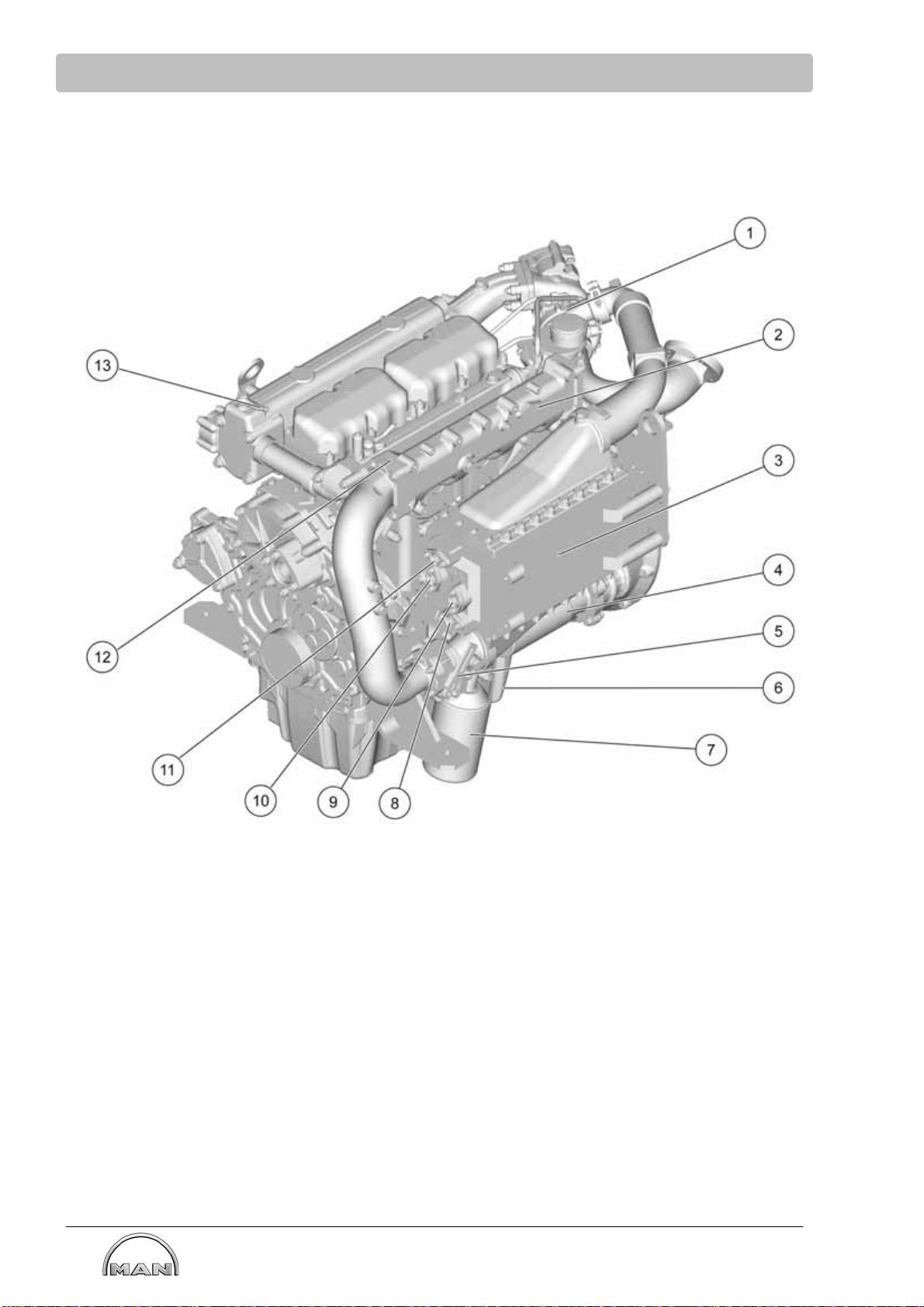
4.2 Engine Views E0834 LE302/ 312/ 322
4.2.1 Front Left View
(1) Turbocharger
(2) Intake manifold
(3) Charge mixture cooler
(4) Starter
(5) Throttle valve
(6) Oil drain screw
(7) Oil filter
(8) Coolant inlet, low‐temperature stage
(9) Coolant outlet, low‐temperature stage
(10) Coolant inlet, high‐temperature stage
(11) Coolant outlet, high‐temperature stage
(12) Flame protection filter
(13) Ventilation connection for coolant to separate ventilation reservoir
Carefully read the Operating Instructions before starting any work!
28
This is especially valid for the chapter on General Safety Instructions
and the safety instructions in each of the chapters.
Page 31
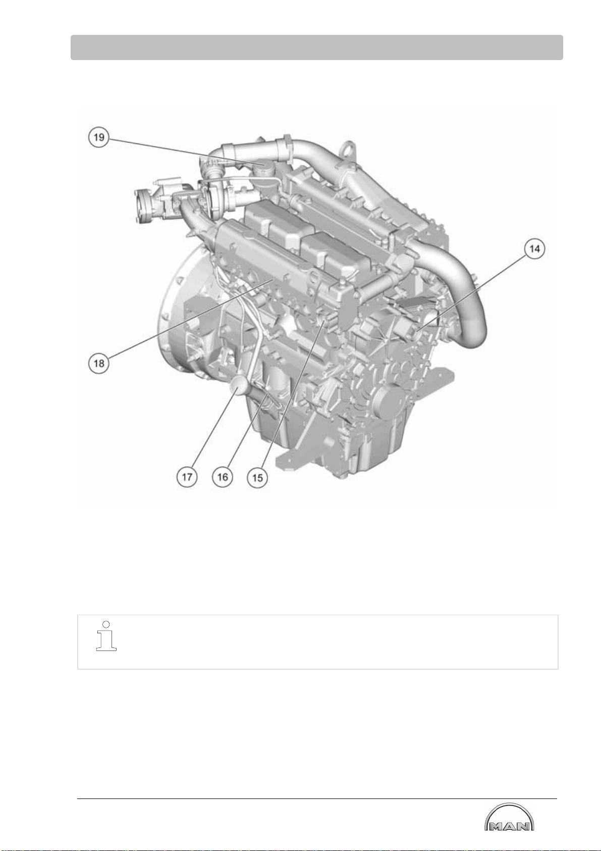
4.2.2 Front Right View
Design and Function
(14) Coolant inlet
(15) Coolant outlet
(16) Oil dipstick
(17) Oil filler neck
(18) Exhaust pipe
(19) Crankcase ventilation
NOTE!
The gas supply line consisting of the ball valve, gas filter, solenoid valves, gas pressure
regulator, gas mixer and air filter are not included in the MAN scope of delivery.
Carefully read the Operating Instructions before starting any work!
This is especially valid for the chapter on General Safety Instructions
and the safety instructions in each of the chapters.
29
Page 32

Design and Function
4.3 Engine Views E0836 LE202
4.3.1 Front Left View
(1) Turbocharger
(2) Intake manifold
(3) Charge mixture cooler
(4) Starter
(5) Throttle valve
(6) Oil drain screw
(7) Oil filter
(8) Oil cooler
(9) Flame protection filter
(10) Ventilation connection for coolant to separate ventilation reservoir
Carefully read the Operating Instructions before starting any work!
30
This is especially valid for the chapter on General Safety Instructions
and the safety instructions in each of the chapters.
Page 33

4.3.2 Front Right View
Design and Function
(5) Oil drain screw
(11) Coolant outlet
(12) Coolant inlet
(13) Oil dipstick
(14) Exhaust pipe
(15) Crankcase ventilation
NOTE!
The gas supply line consisting of the ball valve, gas filter, solenoid valves, gas pressure
regulator, gas mixer and air filter are not included in the MAN scope of delivery.
Carefully read the Operating Instructions before starting any work!
This is especially valid for the chapter on General Safety Instructions
and the safety instructions in each of the chapters.
31
Page 34

Design and Function
4.4 Engine Views E0836 LE302
4.4.1 Front Left View
(1) Turbocharger
(2) Intake manifold
(3) Charge mixture cooler
(4) Starter
(5) Throttle valve
(6) Oil drain screw
(7) Oil filter
(8) Oil cooler
(9) Flame protection filter
(10) Ventilation connection
32
Carefully read the Operating Instructions before starting any work!
This is especially valid for the chapter on General Safety Instructions
and the safety instructions in each of the chapters.
Page 35

4.4.2 Front Right View
Design and Function
(11) Coolant inlet
(12) Coolant outlet
(13) Oil filler neck
(14) Oil dipstick
(15) Oil separator
(16) Bleeder line
NOTE!
The gas supply line consisting of the ball valve, gas filter, solenoid valves, gas pressure
regulator, gas mixer and air filter are not included in the MAN scope of delivery.
Carefully read the Operating Instructions before starting any work!
This is especially valid for the chapter on General Safety Instructions
and the safety instructions in each of the chapters.
33
Page 36

Design and Function
34
Carefully read the Operating Instructions before starting any work!
This is especially valid for the chapter on General Safety Instructions
and the safety instructions in each of the chapters.
Page 37

Design and Function
Carefully read the Operating Instructions before starting any work!
This is especially valid for the chapter on General Safety Instructions
and the safety instructions in each of the chapters.
35
Page 38

Transport, Packaging and Storage
5 Transport, Packaging and Storage
It is absolutely necessary to observe the “Assembly Instructions” for the installation and commissioning of a
new or reconditioned engine.
NOTE!
Installation and commissioning is only to be made by the employees of the manufacturer of
the entire system or by manufacturer authorised personnel.
Nevertheless, as part of the installation and the use of the engine, situations will occur
where the operator or his maintenance personnel will have to be familiar with the handling
of packages. In these situations it is absolutely necessary to observe the following informa
tion.
5.1 Prerequisite
Before starting any work read and observe the General Safety Instructions and the safety information in this
chapter.
Strictly observe these instructions and act prudently to avoid accidents, personal injury and property damage.
Personal Protective Equipment
The following protective equipment must be worn:
S Protective Clothing
S Protective Helmet
S Safety Shoes
S Safety Gloves
5.2 Safety Instructions
Heavy Suspended Loads
WARNING!
Risk of death caused by heavy suspended loads!
During lifting operations, loads can swing out and fall down. This can cause serious injury
and even death.
For this reason:
S Do not stand under or remain in the swivel range of the suspended load.
S Only move the load under supervision.
S Only use approved lifting equipment and accessories with sufficient load capacity.
S Never use torn or scuffed lifting equipment such as ropes or straps.
S Do not let lifting equipment such as rope or straps come into contact with sharp edges
and corners and do not twist or knot them.
S Before leaving the work area, lower load to ground.
36
Carefully read the Operating Instructions before starting any work!
This is especially valid for the chapter on General Safety Instructions
and the safety instructions in each of the chapters.
Page 39

Off-Centre Point of Gravity
WARNING!
Risk of injury caused by falling or tipping packages!
Packages can have a centre of gravity that is off-centre. If the lifting equipment is not hoo
ked up properly, these packages could tip over and fall causing serious injuries.
For this reason:
S Observe the information and markings on the package concerning centre of gravity.
S When transporting with a crane, the hook must be placed so that it is directly above the
package's centre of gravity.
S Carefully raise the package and observe its movement. If necessary, change the position
of the lifting equipment.
Swingout of Packages being Transported
WARNING!
Risk of injury caused by packages swing out during transportation!
When transporting the packages with a crane, the packages can swing out and cause
serious injuries and significant property damage.
Transport, Packaging and Storage
For this reason:
S Ensure that during the transport of packages, no persons, objects or obstacles are in the
swivel range of the packages being transported.
Unauthorised Transport
IMPORTANT!
Risk of property damage if packages are transported by untrained personnel!
Unauthorised transport by untrained personnel can cause packages to fall or tip over. This
could cause considerable property damage.
For this reason:
S Unloading of packages during delivery and their in-house transport are only to be per
formed by trained personnel under the supervision of the manufacturer's employees.
S Refrain from any unauthorised transportation or removal of the transportation aids.
S No unauthorised removal of packaging permitted.
Improper Transport
IMPORTANT!
Risk of property damage caused by improper transport!
Improper transport can cause packages to fall or tip over. This could cause considerable
property damage.
For this reason:
S Carefully handle the packages when unloading during delivery and when transporting
them within the company. Observe the symbols and instructions on the packages.
S Only use the prescribed lifting points.
Carefully read the Operating Instructions before starting any work!
This is especially valid for the chapter on General Safety Instructions
and the safety instructions in each of the chapters.
37
Page 40

Transport, Packaging and Storage
5.3 Transport Inspection
Check the delivery for missing items and for damage from transport.
If external signs of transport damage are apparent:
S Do not accept delivery or only accept under written protest.
S List scope of damage on the transport documents or on the transportation company's packaging slip.
S Initiate a claims process.
S Get engine checked by an expert before it is placed into commission.
NOTE!
Make sure to claim each damage case as soon as it is discovered. Damage claims can only
be claimed within the applicable time limits.
38
Carefully read the Operating Instructions before starting any work!
This is especially valid for the chapter on General Safety Instructions
and the safety instructions in each of the chapters.
Page 41

5.4 Transport
Lifting Points
Transport, Packaging and Storage
There are 2 lifting lugs (1) and (2) for the crane installed on the engine.
WARNING!
Risk of death caused by the load falling!
During lifting operations, loads can fall down. This can cause serious injury and even death.
For this reason:
S The „crane lifting lugs“ are only to be used to transport the engine with no ancillary
assemblies attached.
Carefully read the Operating Instructions before starting any work!
This is especially valid for the chapter on General Safety Instructions
and the safety instructions in each of the chapters.
39
Page 42

Transport, Packaging and Storage
Transport with Crane
The engine can be transported with a crane under the following conditions.
S The crane and the lifting equipment must be designed for the weight of the engine.
S The operator must be qualified for operating the crane.
1. Attach the ropes, straps or multipoint lifting equipment according to the picture.
2. Ensure that the package is hanging straight or compensate for the off-centre point of gravity.
3. Start the transport.
Transport with Forklift
The engine can be transported with a forklift under the following conditions.
S The forklift must be designed for the weight of the engine.
S The engine must be securely mounted to the pallet.
S The pallet must not be damaged.
S The forklift operator must be qualified and authorised to operate the forklift.
1. Insert the fork of the forklift between or under the pallet's struts.
2. The fork must be inserted into the pallet until it protrudes from the other side.
3. Ensure that the pallet cannot tip over if the centre of gravity of off-centre.
4, Lift the pallet and transport it to the desired location.
40
Carefully read the Operating Instructions before starting any work!
This is especially valid for the chapter on General Safety Instructions
and the safety instructions in each of the chapters.
Page 43

Transport, Packaging and Storage
5.5 Packaging
Packaging
The individual packages are packed in accordance with the expected conditions of transport.
The purpose of the packaging is to protect the components from transport damage, corrosion and other
damage. For this reason do not unpack components until shortly before they are to be assembled.
Handling Packing Material
Dispose of packing material according to the valid local and statutory regulations.
IMPORTANT!
Risk of hazard to the environment caused by incorrect disposal!
Packaging materials are valuable raw materials and can in many cases continue to be used
or can be processed and recycled. Incorrect disposal of packaging materials may cause an
environmental hazard.
For this reason:
S Dispose of packing materials in an environmentally friendly manner.
S Observe the valid local regulations. If necessary, contact a professional disposal com
pany.
5.6 Storage
Storage of packages
Store packages under the following conditions:
S Do not store in the open.
S Store in a dry and dust-free environment.
S Do not expose to damaging chemicals.
S Protect from sun light.
S Avoid any physical shocks.
S Storage temperature: 15 to 35 °C.
S Relative humidity: max. 60 %.
S If stored for more than 3 months, regularly check the condition of the packaging. If necessary, renew or
replace the preservation.
NOTE!
Some of the packages may have information printed on them regarding their proper sto
rage. Please observe this information.
Carefully read the Operating Instructions before starting any work!
This is especially valid for the chapter on General Safety Instructions
and the safety instructions in each of the chapters.
41
Page 44

Installation and Commissioning
6 Installation and Commissioning
6.1 Prerequisite
Before starting any work read and observe the General Safety Instructions and the safety information in this
chapter.
Strictly observe these instructions and act prudently to avoid accidents, personal injury and property damage.
Personal Protective Equipment
The following protective equipment must be worn:
S Protective Clothing
S Safety Shoes
S Safety Gloves
6.2 Safety Instructions
Personnel
S The installation and commissioning may only be performed by MAN employees or by MAN-trained quali
fied personnel.
Ground Rules
WARNING!
Danger caused by faulty installation and commissioning!
Installation and commissioning require trained qualified personnel with sufficient experi
ence. Faulty installation can cause life threatening situations and considerable property
damage.
For this reason:
S Installation and commissioning are only to be performed by MAN employees.
S Installation and commissioning by MAN trained qualified personnel may only be per
formed with approval from MAN.
WARNING!
Risk of injury caused by improper installation and commissioning!
Improper installation and commissioning can cause serious personal injury or considerable
property damage.
For this reason:
S Ensure adequate work space before starting any work.
S Be careful when working with exposed parts with sharp edges.
S Make sure work space is kept clean and orderly!
S Install components in a correct manner.
S Observe the prescribed tightening torques.
S Secure components so that they do not fall or tip over.
S Before commissioning the engine, carefully read the Operating Instructions and familiarise yourself with
the “critical” subjects.
S It is absolutely necessary to observe the “Assembly Instructions” for the installation and commissioning
of a new or reconditioned engine.
Carefully read the Operating Instructions before starting any work!
42
This is especially valid for the chapter on General Safety Instructions
and the safety instructions in each of the chapters.
Page 45

Installation and Commissioning
S For safety reasons we recommend placing an off limits sign on the door to the engine room and to in
struct the operating personnel that they are responsible for the safety of people who enter the engine
room.
6.3 Installation - Engine
The installation of the engine, i.e. connection to the power supply, connection of the cooling system, are to
be performed in accordance with the manufacturer's instructions for the entire system and with the help of
the “Assembly Instructions”.
6.3.1 Safety Equipment
WARNING!
Risk of death caused by the absence of safety equipment!
An emergency-off button, for shutting down the system or engine in an emergency, must be
installed for each engine.
For this reason:
S Install an emergency stop button to shut down the system in an emergency.
S Check whether all of the safety equipment is correctly installed and in good operating or
der.
WARNING!
Risk of death caused by faulty operation!
At excessive loads or if malfunctions occur the engine can overheat and suddenly seize.
For this reason:
S The sensors which monitor the engine parameters must be connected to and evaluated
by the module manufacturer's monitoring equipment.
S If sensor values go outside the permissible limits or if there is a power loss, the engine
must be able to be immediately shut off by the monitoring equipment.
The following sensors are installed in the engine:
S Exhaust temperature
S Oil pressure
S Coolant temperature
6.3.2 Engine Model Plate Data
Please always specify the engine model, engine number and order number when corresponding with MAN,
see page .
For this reason, before commissioning the engine, read off the data from the engine model plate and enter
it into the Engine Model Plate chapter, see page 25.
Carefully read the Operating Instructions before starting any work!
This is especially valid for the chapter on General Safety Instructions
and the safety instructions in each of the chapters.
43
Page 46

Installation and Commissioning
6.4 Commissioning
New or reconditioned engines must not be operated during the first operating hours at loads higher than
3/4 power.
After this time period the engine can be slowly brought up to full power.
IMPORTANT!
Termination of liability for material defects by use of non-approved fluids and lubric
ants!
Liability of material defects is terminated if non-approved fluids and lubricants are used.
For this reason:
S Only use approved fluids and lubricants (see “Fluids and Lubricants ..." publication).
S The requirements on the quality of gas are specified in “MAN data sheet - Minimum re
quirement on the quality of gas for MAN gas engines"
6.4.1 Gas System
NOTE!
The gas supply line is not included in MAN's scope of delivery. Commissioning, operation,
monitoring of operating conditions, and maintenance of the gas system are all to be per
formed as described in the manufacturer's instructions.
Setting for commissioning
For commissioning the engine is to be set for the use of a suitable gas/air mixture. Any deviations from this
will negatively influence the output power, the engine efficiency and the exhaust emissions.
The requirements on the quality of gas are specified in ”MAN data sheet - Minimum requirement on the qu
ality of gas for MAN gas engines".
The operating pressure of the natural gas in the gas line must be at least 20 mbar.
The gas pressure should be steady within this range.
To get a correct gas/air mixture the air in the engine room must have a temperature of between 10_
and 30_C.
The gas must not contain any condensation when it enters the gas mixer, see “MAN data sheet - Minimum
requirement on the quality of gas for MAN gas engines".
Faults
We urgently recommend that you have faults rectified only at an authorised specialist workshop.
Air filter
The maximum pressure differential up and downstream of the filter may not exceed the following:
New w 10 hPA
Dirty x 30 hPA
The filter element must therefore be changed as stated in the maintenance instructions.
Gas filter
The gas filter must filter grain size x 6 mm.
Carefully read the Operating Instructions before starting any work!
44
This is especially valid for the chapter on General Safety Instructions
and the safety instructions in each of the chapters.
Page 47

Installation and Commissioning
6.4.2 Filling Coolant
NOTE!
Do not let coolant drip or leak out while filling. Do not let coolant leak out onto the ground or
into bodies of water. Otherwise, the environment will be damaged.
The engine's cooling system is to be filled with a mixture of tap water and antifreeze (ethylene glycol or an
ticorrosion agent). Coolant must be filled according to the filling specifications of the BHKW (combined heat
and power plant) manufacturer.
For suitable antifreeze agents see approved Fuels, Lubricants and Coolants according to MAN 324 NF and
MAN 248.
Coolant may only be filled at the filler neck.
S Remove cap.
S Slowly fill coolant.
S Close expansion reservoir.
S Run engine for approx. 15 minutes at rated speed.
S Shut off engine and carefully unscrew cap with safety valve to the first stop to release pressure, then
carefully open. Add coolant if necessary.
S When adding coolant, do not add cold coolant to a warmed-up engine. Ensure that the proper mixing
ratio of “water/antifreeze" is met.
S Check coolant before the next commissioning (with engine cold). Add coolant if necessary.
S Repeat this procedure until coolant can no longer be added.
Carefully read the Operating Instructions before starting any work!
This is especially valid for the chapter on General Safety Instructions
and the safety instructions in each of the chapters.
45
Page 48

Installation and Commissioning
6.4.3 Filling Engine Oil
IMPORTANT!
Component damage caused by
over filling!
Engine damage can occur if engine
oil is filled to above the max. mark
on the oil dipstick.
For this reason:
S Do not fill engine oil above the
max. mark on the oil dipstick
1. Remove cap.
2. Slowly fill engine oil into the filler neck.
For oil filling capacity, see “Technical Data”
page 68.
MAX
MIN
3. Reinstall cap.
46
Carefully read the Operating Instructions before starting any work!
This is especially valid for the chapter on General Safety Instructions
and the safety instructions in each of the chapters.
Page 49

Installation and Commissioning
Carefully read the Operating Instructions before starting any work!
This is especially valid for the chapter on General Safety Instructions
and the safety instructions in each of the chapters.
47
Page 50

Operation
7 Operation
7.1 Prerequisite
Before starting any work read and observe the General Safety Instructions and the safety information in this
chapter.
Strictly observe these instructions and act prudently to avoid accidents, personal injury and property damage.
Personal Protective Equipment
The following protective equipment must be worn:
S Protective Clothing
S Safety Shoes
S Safety Gloves
7.2 Safety Instructions
Personnel
S Operation of the engine may only be performed by instructed personnel or bytrained qualified personnel.
Ground Rules
WARNING!
Danger caused by faulty operation!
Improper operation can cause serious personal injury or considerable property damage.
For this reason:
S Perform all operating steps in accordance with the instructions in these Operating Instruc
tions.
S Before starting any work ensure that all covers and protective equipment have been in
stalled and are operating properly.
S Never shut off any safety equipment while in operation.
S Make sure work space is kept clean and orderly! Any unused parts or components lying
around are potential sources of accidents.
WARNING!
Risk of injury caused by vapours!
In the first operating hours of the engine the paint on hot engine parts will burn off produ
cing vapours that are hazardous to health.
For this reason:
S Ensure sufficient ventilation.
S Limit time spent in the engine area to the absolute minimum.
48
Carefully read the Operating Instructions before starting any work!
This is especially valid for the chapter on General Safety Instructions
and the safety instructions in each of the chapters.
Page 51
7.3 Preparations before Operation
DANGER!
Danger caused by damaged engines!
Damaged engines can be dangerous to persons.
For this reason:
S Check engine for damage and leaks before each operation.
S Do not operate engine if damage is found.
Before each operation check the engine's coolant and oil level.
If necessary add coolant and engine oil.
IMPORTANT!
Termination of liability for material defects by use of non-approved fluids and lubric
ants!
Liability of material defects is terminated if non-approved fluids and lubricants are used.
For this reason:
S Only use approved fluids and lubricants (see “Fluids and Lubricants ..." publication).
Operation
7.3.1 Check Gas Quality, Open Gas Supply
WARNING!
Risk of fire caused by highly flammable substances!
Highly flammable substances, fluids or gases can catch on fire and cause serious or deadly
injuries.
For this reason:
S Do not smoke in the hazard area or in the vicinity.
No open fires or sources of ignition.
S Keep fire extinguishers at hand.
S Immediately report any suspicious substances, fluids or gases to the person in charge.
S In the case of fire, immediately stop working. Leave hazard area until the danger is over.
1. Check the quality of the gas, see “MAN data sheet - Minimum requirement on the quality of gas for
MAN gas engines".
2. Open gas supply.
7.3.2 Checking Coolant
WARNING!
Risk of scalding!
The cooling system is under pressure and the coolant is hot.
For this reason:
S Let engine cool down.
NOTE!
The cooling system is not included in MAN's scope of delivery.
Check the coolant level according to the manufacturer's operating manual.
Carefully read the Operating Instructions before starting any work!
This is especially valid for the chapter on General Safety Instructions
and the safety instructions in each of the chapters.
49
Page 52

Operation
7.3.3 Refilling Coolant
NOTE!
Do not let coolant drip or leak out while refilling. Do not let coolant leak out onto the ground
or into bodies of water otherwise this will cause damage to the environment.
IMPORTANT!
Engine damage caused by excessive temperature difference!
When refilling with cold coolant in an engine at operating temperature there is a risk of en
gine damage caused by excessive temperature difference.
For this reason:
S Do not fill with cold coolant.
Fill the cooling system of the engine with a mixture of tap water and ethylene glycol antifreeze agent or an
ticorrosion agent.
NOTE!
The cooling system is not included in MAN's scope of delivery.
Add coolant according to the manufacturer's operating manual.
50
Carefully read the Operating Instructions before starting any work!
This is especially valid for the chapter on General Safety Instructions
and the safety instructions in each of the chapters.
Page 53

7.3.4 Checking Engine Oil Level
NOTE!
Check the oil level when the engine is horizontal and only after at least 20 minutes have
passed since the engine was switched off.
1. Pull out oil dipstick (1).
2. Wipe off oil dipstick (1) with a lint-free, clean
cloth.
3. Reinsert the oil dipstick (1) all the way.
4. Pull out oil dipstick (1) again and check oil level.
The oil level should be between both of the marks
on the dipstick and should never drop below the
lower mark.
5. Reinsert the oil dipstick (1) all the way.
If the oil level is too low, refill with new oil.
Operation
1
MAX
MIN
Carefully read the Operating Instructions before starting any work!
This is especially valid for the chapter on General Safety Instructions
and the safety instructions in each of the chapters.
51
Page 54
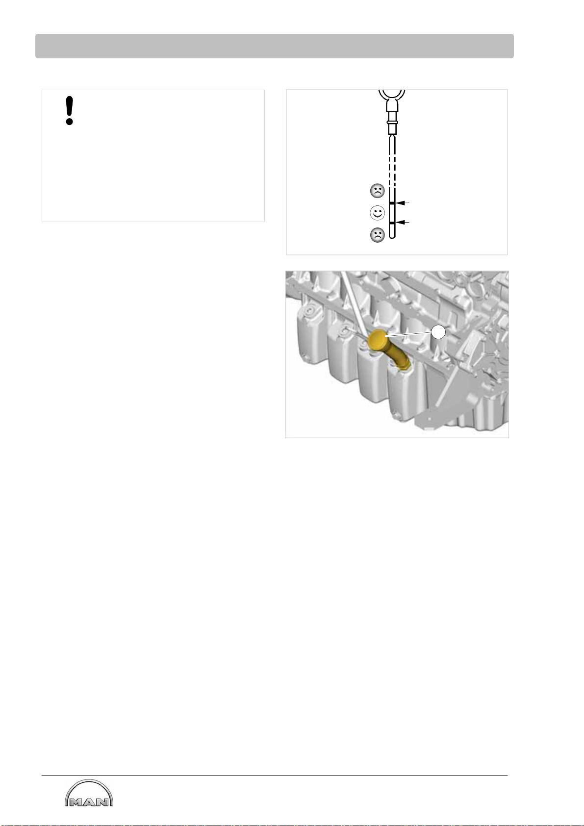
Operation
7.3.5 Refilling Engine Oil
IMPORTANT!
Component damage caused by
over filling!
Engine damage can occur if engine
oil is filled to above the max. mark
on the oil dipstick.
For this reason:
S Do not fill engine oil above the
max. mark on the oil dipstick
1. Remove cap (1).
2. Slowly fill engine oil into the filler neck.
The oil level should be between both marks on the
dipstick.
3. Reinstall cap (1).
MAX
MIN
1
4. Check engine oil level.
52
Carefully read the Operating Instructions before starting any work!
This is especially valid for the chapter on General Safety Instructions
and the safety instructions in each of the chapters.
Page 55

7.4 Operation
DANGER!
Risk of injury caused by mechanical movements, gases and noise.
There is a risk of injury during engine operation caused by moving engine parts and from
engine emissions.
For this reason:
S Access to operating room is only allowed for maintenance/repairs.
S Access to operating room is prohibited when engine is running.
S Ensure that no persons are in the operating room and secure it from unauthorised ac
cess.
7.4.1 Starting Engine
DANGER!
Risk of injury caused by moving parts!
Rotating or linear moving parts can cause serious or deadly injuries.
For this reason:
S Before starting engine check whether all protective equipment have been properly in
stalled.
S Remove tools and aids out of the hazard area.
S Before starting make sure that no-one is in the engine's danger area.
Operation
The electronic ignition system is a high-voltage condensator ignition system (based on crankshaft rotation)
with a microprocessor control.
The ignition system muss be parameterized before commissioning. For further information please refer to
the operating manual of the ignition system and to the assembly instructions.
Turn on coolant pump before starting engine.
Turn on starter and run for at least 3 seconds to ensure engine is purged with air.
After purging engine with air the ignition system and the gas supply line can be turned on (this is usually
done automatically).
NOTE!
A start phase consists of a maximum 3 consecutive start attempts each lasting 12 seconds.
If no rpm signal is detected within 3 seconds, the start process is to be cancelled. The
pauses between 2 start attempts must be at least 30 seconds. A pause of at least 300
seconds must be maintained until the initiation of the next start phase.
When the rated speed has been reached, the plant can then be operated under load.
Acceleration of the engine from 0% to 100% is made over a time interval of 3 minutes.
This minimises the thermal load on the engine block.
The oil-pressure gauge must indicate the lubrication oil pressure. If this is not the case, immediately shut
off engine.
Carefully read the Operating Instructions before starting any work!
This is especially valid for the chapter on General Safety Instructions
and the safety instructions in each of the chapters.
53
Page 56

Operation
7.4.2 Monitoring Operation
IMPORTANT!
Do not overload engine.
If faults occur, investigate and solve them immediately to prevent major damage from oc
curring!
The oil pressure and the coolant temperature are constantly monitored during engine operation.
If the limits are exceeded or gone below, the engine will be automatically shut off.
7.4.3 Stopping in an Emergency
An emergency-off button, for shutting down the system in an emergency, must be installed for each engine.
7.4.4 Engine Shut Off
Deceleration of the engine from 100% to 0% is made using a ramp in a time interval of at least 3 minutes.
This minimises the thermal load on the engine block.
DANGER!
Risk of fire caused by unburned gases!
The gas supply is always to be turned off before the ignition system is turned off. This en
sures that no unburned gas can reach the exhaust system.
For this reason:
S If there is damage to the engine shutoff device, do not shut off engine by shutting off igni
tion system.
S Close main gas valve.
S Turn off ignition system after engine is at a standstill.
S Ensure that the engine cannot be started by unauthorised persons.
1. Shut off gas supply.
2. The engine stops running.
3. After waiting 5 seconds, turn off ignition system and control system.
NOTE!
The coolant pump will run on for approx. 5 minutes after engine has stopped.
This minimises the thermal load to the engine block.
54
Carefully read the Operating Instructions before starting any work!
This is especially valid for the chapter on General Safety Instructions
and the safety instructions in each of the chapters.
Page 57

Maintenance and Care
8 Maintenance and Care
WARNING!
Risk of injury to incorrectly executed maintenance
Improper maintenance can case serious injuries or considerable property damage.
For this reason:
S Before carrying out maintenance work, read the maintenance instructions carefully.
S Perform all maintenance steps in accordance with the maintenance instruction.
8.1 Maintenance instructions
Maintenance instructions for the engines are available to supplement these operating instructions.
It contains a discription of all due turnaround maintenace work.
Maintenance instruction see leaflet “Maintenance Instruction MAN Industriel Gas Engines”
8.2 Maintenance Schedule
The Maintenance schedule for the engines are available to supplement the maintenance instructions.
The maintenance schedule contains all the maintenance work, which has to be carried out at specified time
intervals or on reaching a specified number of operating hours.
Maintenance Schedule see leaflet “Maintenance Record MAN Industriel Gas Engines”
8.3 Repair instructions
The repair instructions contain a detailed description of all installation and adjustment actions required on
the engine. This work must only be undertaken by specialist personnel trained for the repair work.
Carefully read the Operating Instructions before starting any work!
This is especially valid for the chapter on General Safety Instructions
and the safety instructions in each of the chapters.
55
Page 58

Maintenance and Care
56
Carefully read the Operating Instructions before starting any work!
This is especially valid for the chapter on General Safety Instructions
and the safety instructions in each of the chapters.
Page 59

Faults
9 Faults
The following chapter describes the possible faults which can occur and the work to correct them.
For those faults that cannot be rectified by the following information, contact the manufacturer of the entire
system or MAN Service.
9.1 Prerequisite
Before starting any work read and observe the General Safety Instructions and the safety information in this
chapter.
Strictly observe these instructions and act prudently to avoid accidents, personal injury and property damage.
9.2 Safety Instructions
Personnel
S Engine faults may only be rectified by specially trained qualified personnel or by the manufacturer of the
entire system.
Personal Protective Equipment
The following protective equipment must be worn:
S Protective Clothing
S Safety Shoes
S Safety Gloves
Ground Rules
WARNING!
Risk of injury caused by improper rectification of faults!
Improper rectification of faults can case serious injuries or considerable property damage.
For this reason:
S Ensure that the engine cannot be started be unauthorised persons.
S Ensure adequate work space before starting any work.
S Make sure work space is kept clean and orderly! Any unused parts or components lying
around are potential sources of accidents.
Carefully read the Operating Instructions before starting any work!
This is especially valid for the chapter on General Safety Instructions
and the safety instructions in each of the chapters.
57
Page 60

9.3 Fault Table
Fault Possible cause Remedy
Engine does not start D Shutoff solenoid valve of gas supply
closed/does not open
D Zero pressure regulator of gas supply
not correctly set or faulty
D Air filter clogged
D Exhaust clogged
(exhaust back pressure too high)
D Electric circuit interrupted
D Set main switch to "on"
D Replace faulty fuses
D Repair any loose, corroded and
broken wires and contacts
Faults
Engine starts but does
not reach idle speed or
stalls
Engine does not start
or poorly starts in war
med up condition
D Battery dead
D Starter/solenoid switch faulty
D Ignition system control unit faulty
D Impulse sensor faulty
D Spark plugs faulty or worn
D Spark plug connectors wet
D Ignition timing incorrect
D Gas inlets in gas mixer (venturi pipe)
clogged/oiled
D Valves do not close or are stuck
D Crank assembly is externally blocked
D Engaging lever/bearing pin of engaging
lever broken
D Internal engine damage (piston seizure,
maybe due to incorrect oil type)
D Quality of gas does not meet the specifi
cations or is contaminated
D Throttle valve does not open/actuation
level sticks/actuator is de-energized or
faulty
D Air filter clogged
D Spark plug faulty
D Ignition cable faulty
D Ignition coil faulty
D Ignition timing incorrectly set
D Insufficient compression in cylinder or
more than 3-4 bar pressure difference
between the cylinders
D See information at "Starter"
D Clearance incorrectly set
D A faulty tank system can cause
oil to get into the pressure gas
system. Clean entire system.
D Remove objects that interfere
with the movement of the fan,
power output, alternator, etc.
D Remedy from manufacturer ser
vice
D See "Fluids and Lubricants...."
D Remedy from manufacturer ser
vice
D Remedy from manufacturer ser
vice
58
Carefully read the Operating Instructions before starting any work!
This is especially valid for the chapter on General Safety Instructions
and the safety instructions in each of the chapters.
Page 61

Fault RemedyPossible cause
Engine does not start
or poorly starts in cold
condition
Rough idling with en
gine warm,
misfiring
Engine speed fluctua
tions during operation
Poor performance D Spark plug faulty
D Spark plug faulty
D Ignition cable faulty
D Ignition coil faulty
D Ignition timing incorrectly set
D Starter turns slowly
D Check quality of gas
D Spark plug faulty
D Ignition cable faulty
D Ignition coil faulty
D Ignition timing incorrectly set
D Valve clearance not OK
D Zero pressure regulator of gas supply
not correctly set or faulty
D Insufficient compression in cylinder or
more than 3-4 bar pressure difference
between the cylinders
D Spark plug faulty
D Ignition cable faulty
D Ignition coil faulty
D Ignition timing incorrectly set
D Shutoff solenoid valve of gas supply
closed/does not open
D Tachometer faulty
D Gas pressure regulator faulty
D Oxygen sensor faulty
D Ignition cable faulty
D Ignition coil faulty
D Ignition timing incorrectly set
D Throttle valve not in full throttle position,
actuation linkage sticks,
throttle valve incorrectly adjusted
D Zero pressure regulator of gas supply
not correctly set or faulty
D Gas metering valve faulty
D Gas/air mixture too rich or too lean
D Too much power is demanded from the
engine than it can produce
D Gas quality does not meet the regu
lations
D Cross section of oxygen regulation
valve is not set to the current gas quality
D Oil level in oil pan too high
Faults
D Remedy from manufacturer ser
vice
D Battery with insufficient charge
or damaged
D Voltage drop between battery
and starter too high
D Remedy from manufacturer ser
vice
D Remedy from manufacturer ser
vice
D See "Fluids and Lubricants..."
D Remedy from manufacturer ser
vice
D Check whether the guide tube is
correctly installed and the cor
rect oil dipstick is being used
D If coolant is discovered in the
engine oil, check cylinder head
gasket, cylinder liner gasket and
piston rings
Carefully read the Operating Instructions before starting any work!
This is especially valid for the chapter on General Safety Instructions
and the safety instructions in each of the chapters.
59
Page 62

Fault RemedyPossible cause
Poor performance D Air filter clogged
D Exhaust pipe clogged
D Air intake pipe leaks
D Charge mixture cooler dirty/leaks
D Charge mixture ducting leaks
D Turbocharger leaks, faulty, dirty
D Insufficient compression in cylinder or
more than 3-4 bar pressure difference
between the cylinders
Coolant temperature
too high, loss of coolant
Lube-oil pressure too
low
Lube-oil pressure too
high
D Coolant level too low
D Air in coolant circuit
D Radiator very dirty, fins clogged
D V-belt for coolant pump not correctly
tightened (slips)
D Cap with work valves on expansion
reservoir/radiator is faulty or leaks
D Temperature display faulty
D Coolant pump leaks, defective (bearing
damage)
D Thermostat faulty, does not open
D Coolant lines leak, clogged or twisted D Remedy from manufacturer ser
D Oil level in oil pan too low
D Engine temperature to high
D Oil pressure indicator faulty
D Selected oil viscosity is inappropriate for
ambient temperature (too thin)
D Oil in oil pan is too thin (contains con
densation)
D Bearing heavily worn
D Oil pump gears heavily worn
D Safety valve in oil circuit faulty (does not
close, spring is worn or broken)
D Engine cold
D Selected oil viscosity is inappropriate for
ambient temperature (too thick)
D Oil pressure indicator faulty
D Safety valve in oil circuit faulty (does not
open)
D Oil lines/oil ducts clogged
Faults
D Remedy from manufacturer ser
vice
vice
D See "Fluids and Lubricants..."
D Remedy from manufacturer ser
vice
D See "Fluids and Lubricants..."
D Remedy from manufacturer ser
vice
60
Carefully read the Operating Instructions before starting any work!
This is especially valid for the chapter on General Safety Instructions
and the safety instructions in each of the chapters.
Page 63

Fault RemedyPossible cause
Lube-oil consumption
too high
Gas consumption too
high
Blue smoke D Lube oil penetrates into combustion
White smoke D Coolant penetrates into combustion
Engine knocking D Ignition timing incorrectly set
Engine too "loud" D Intake or exhaust pipe leaks
Exhaust temperature/
exhaust back pressure
too high (thermal over
load)
D Lube-oil quality does not meet the regu
lations
D Oil level in oil pan too high
D Leaks in lube-oil circuit especially at the
turbocharger and oil cooler
D Piston rings heavily worn
D Valve stems heavily worn, bent
D Crankcase breather clogged
D Gas quality does not meet the regu
lations
D Ignition timing incorrectly set
D Charge mixture cooler dirty/leaks
D Charge mixture ducting leaks
D Valve seat leaks
D Air filter clogged
D Exhaust gas recirculation cooler dirty
chamber (pistons/piston rings worn or
piston rings broken)
D Turbine and compressor impeller in tur
bocharger dirty (rough running, out of
balance)
D Valve stem/guide worn
chamber (cylinder head/gasket leaks)
D Valve clearance not OK
D Valves stick
D Piston pin or crankshaft bearing loose
D Piston ring broken
D Timing gears worn, gear backlash too
large
D Valve clearance too large
D Turbine and compressor impeller in tur
bocharger dirty (rough running, out of
balance)
D Poly-V-belt slips
D Engine bearing not suitable/worn
D Unsuitable exhaust piping; heat ex
changer and catalytic converter have
too high resistance
Faults
D See "Fluids and Lubricants..."
D Check whether the guide tube is
correctly installed and the cor
rect oil dipstick is being used
D If coolant is discovered in the
engine oil, check cylinder head
gasket, cylinder liner gasket and
piston rings
D Remedy from manufacturer ser
vice
D See "Fluids and Lubricants..."
D Check intake vacuum
D Remedy from manufacturer ser
vice
D Check exhaust back pressure
D Remedy from manufacturer ser
vice
D Check thermostat
D Remedy from manufacturer ser
vice
D Remedy from manufacturer ser
vice
D Remedy from manufacturer ser
vice
Carefully read the Operating Instructions before starting any work!
This is especially valid for the chapter on General Safety Instructions
and the safety instructions in each of the chapters.
61
Page 64

Starter
Faults
Fault
D Pinion gear does not
turn or turns slowly
D Pinion gear does not
engage
D Pinion gear
engages, but stops
turning
D Pinion gear conti
nues to turn after
starter switch is re
leased
D Pinion gear does not
disengage after en
gine starts
Possible cause Remedy
To be repaired by a vehicle elec
trician or by the manufacturer
service
D Battery has insufficient charge
D Terminal is loose, oxidised, poor
connection to ground
D Starter terminal or carbon brushes are
short circuited to ground
D Carbon brushes stick or have poor con
tact
D Pinion gear or starter ring gear are very
dirty or damaged
D Solenoid switch faulty
D Overrunning clutch slips
D Starter switch faulty
D Solenoid switch faulty
D Starter faulty
D Immediately shut down engine
62
Carefully read the Operating Instructions before starting any work!
This is especially valid for the chapter on General Safety Instructions
and the safety instructions in each of the chapters.
Page 65

Decommissioning and Recommissioning
10 Decommissioning and Recommissioning
10.1 Prerequisite
Before starting any work read and observe the General Safety Instructions and the safety information in this
chapter.
Strictly observe these instructions and act prudently to avoid accidents, personal injury and property damage.
Personal Protective Equipment
The following protective equipment must be worn:
S Protective Clothing
S Safety Shoes
S Safety Gloves
10.2 Safety Instructions
Personnel
S Decommissioning and recommissioning of the engine may only be made be trained and qualified per
sonnel.
Ground Rules
WARNING!
Risk of injury caused by improper work.
Improper work can case serious injuries or considerable property damage.
For this reason:
S Ensure that the engine cannot be started be unauthorised persons.
S Perform all work steps in accordance with the instructions in these Operating Instructions.
S Ensure adequate work space before starting any work.
S Make sure work space is kept clean and orderly! Any unused parts or components lying
around are potential sources of accidents.
Carefully read the Operating Instructions before starting any work!
This is especially valid for the chapter on General Safety Instructions
and the safety instructions in each of the chapters.
63
Page 66

Decommissioning and Recommissioning
10.3 Temporary Decommissioning of Engines
Temporary anticorrosion protection according to MAN works norm M 3069 is required for engines which are
to be put out of service depending on the duration.
The works norm can be obtained from our After-Sales Service department Nuremberg works.
NOTE!
A proper and careful recommissioning of new or operated engines has a great impact on
the operating safety and remaining life of the engines.
In general the goal is to preserve the decommissioned engines or new engines (after the
factory tests).
If the engine was not preserved before decommissioning, there is a risk that the cylinder
liners, piston rings and valves will corrode, especially when the intake and exhaust opening
are not closed off or when the engine is stored in the open.
Foreign matter, rain water and similar conditions require a complete disassembly of the en
gine.
64
Carefully read the Operating Instructions before starting any work!
This is especially valid for the chapter on General Safety Instructions
and the safety instructions in each of the chapters.
Page 67

Decommissioning and Recommissioning
10.4 Recommissioning of Decommissioned Engines
10.4.1 Commissioning of Preserved Engines according to MAN-Werknorm M 3059
1. Remove external preservation. Never use a high pressure cleaner for this.
2. Remove caps from intake and exhaust openings.
3. Check cooling system; add antifreeze according to the Fluids and Lubricants list (see “Fluids and Lubric
ants ..."); check concentration and correct.
4. Check engine oil level and add fresh approved engine oil if necessary.
5. Check the operation of the monitoring and emergency shut off equipment.
6. Check condition and proper installation of elastic fasteners, such as V-belts, coolant hoses and charge
air hoses. Retighten if necessary.
7. Rotate engine with gas supply turned off until oil pressure builds up. Operate starter no more than 12
seconds for this.
8. Open gas supply and start engine. After engine is running, operate engine above idle speed to avoid
insufficient lubrication of the cylinder liners.
9. Check engine for leaks, unusual noises and observe the oil pressure and all temperatures. Increase en
gine speed in steps.
10.After a max. of 25 operating hours, drain preservation oil from engine and change oil filter; fill engine
with fresh approve engine oil.
10.4.2 Commissioning of Non-Preserved Engines
In addition to the work steps for a preserved engine, the commissioning of a non-preserved engine requires
the following extra work depending on the possible nonuse damages.
1. Check combustion chambers with an endoscope, to do this, remove/install spark plugs.
Check valve for easy movement; check valve clearance and adjust if necessary.
Replace any damaged/corroded parts.
2. Drain old oil from engine and change oil filter. Fill engine with fresh approved engine oil.
3. Check cooling system for corrosion; check coolant for proper concentration; if in doubt, change coolant.
Before adding new coolant , clean coolant chambers and remove/install coolant pump and thermostat if
necessary; replace the slide ring seal of the coolant pump and thermostat elements; pressure test cool
ing system.
4. Check clean air system, air filter and turbocharger for dirt and corrosion. Clean or repair if necessary.
5. Clean/check/replace gas filter.
Carefully read the Operating Instructions before starting any work!
This is especially valid for the chapter on General Safety Instructions
and the safety instructions in each of the chapters.
65
Page 68

Decommissioning and Recommissioning
66
Carefully read the Operating Instructions before starting any work!
This is especially valid for the chapter on General Safety Instructions
and the safety instructions in each of the chapters.
Page 69

11 Technical Data
11.1 Dimensions and Weights
11.1.1 E0834 LE302
Technical Data
Specification Value Unit
Weight (dry)
E0834 LE302 495 kg
A 1055 mm
B 809 mm
C 866 mm
11.1.2 E0836 LE202
11.1.2 E0836 LE302
Specification Value Unit
Weight (dry)
E0836 LE202 605 kg
A 1300 mm
B 740 mm
C 1030 mm
Specification Value Unit
Weight (dry)
E0836 LE202 605 kg
A 1300 mm
B 740 mm
C 1030 mm
11.2 Installation Location and Space Requirements
Observe the information in the Assembly Instructions.
Carefully read the Operating Instructions before starting any work!
This is especially valid for the chapter on General Safety Instructions
and the safety instructions in each of the chapters.
67
Page 70

Technical Data
11.3 Engine Data
11.3.1 E0834 LE302
Engine model E0834 LE302
Design Inline engine
Operating Principle 4-cycle spark ignition engine
Number of cylinders 4
Bore 108 mm
Stroke 125 mm
Displacement 4,580 cm
Compression 11:1
Rating
for natural gas operation 68 kW / 92 HP at 1500 rpm
The power output specifications are valid for operation with natural gas with a calorific value of
36,350 kJ/m3 and a methane number > 80. For higher calorific values, the engine is to be set so
that the specified engine power is not exceeded. For lower calorific values a correspondingly lower
engine power will be the result. A new engine setup will be needed to achieve the rated output.
3
Rating
for biogas operation 66 kW / 90 HP at 1500 rpm
The power output specifications are valid for operation with biogas (60% CH4, 40% CO2 with a calo
rific value of 17,600 kJ/m3 and a methane number 140. For higher calorific values, the engine is to
be set so that the specified engine power is not exceeded. For lower calorific values a correspondin
gly lower engine power will be the result. A new engine setup will be needed to achieve the rated
output.
Firing order 1-3-4-2
Valve clearance (cold engine)
Intake 0.50 mm
Exhaust 0.50 mm
Valve timing
Intake opens 6 before TDC
Intake closes 38 after BDC
Exhaust opens 56 before BDC
Exhaust closes 12 after TDC
Ignition timing in _ KW before TDC Natural gas operation Biogas operation
1500 rpm, 50C mixture temperature 16_ 18_
1800 rpm, 50C mixture temperature -- --
68
Carefully read the Operating Instructions before starting any work!
This is especially valid for the chapter on General Safety Instructions
and the safety instructions in each of the chapters.
Page 71

Engine lubrication Force feed lubrication
Technical Data
Lubrication oil pressure during ope
ration (depends on engine speed,
oil temperature and engine load)
Oil filter Single-use main flow filter (easy-change filter)
Oil capacity in oil sump (litres) min. max.
half deep 17 l 25 l
Oil change quantity (with filter) 26 l
Engine cooling system Liquid cooling
Coolant temperature
Inlet temperature min. 80_C
Outlet temperature max. 88°C
Coolant filling capacity in engine approx. --
Electrical equipment
Starter 24 V; 4 KW
Test values
Lambda (oxygen) 1.62 1.42
must be monitored via an oil pressure monitor or a display device
Natural gas operation Biogas operation
Carefully read the Operating Instructions before starting any work!
This is especially valid for the chapter on General Safety Instructions
and the safety instructions in each of the chapters.
69
Page 72

Technical Data
11.3.1 E0834 LE312
Engine model E0834 LE312
Design Inline engine
Operating Principle 4-cycle spark ignition engine
Number of cylinders 4
Bore 108 mm
Stroke 125 mm
Displacement 4,580 cm
Compression 11:1
Rating
for natural gas operation 68 kW / 92 HP at 1500 rpm
The power output specifications are valid for operation with natural gas with a calorific value of
36,350 kJ/m3 and a methane number > 80. For higher calorific values, the engine is to be set so
that the specified engine power is not exceeded. For lower calorific values a correspondingly lower
engine power will be the result. A new engine setup will be needed to achieve the rated output.
3
Firing order 1-3-4-2
Valve clearance (cold engine)
Intake 0.50 mm
Exhaust 0.50 mm
Valve timing
Intake opens 6 before TDC
Intake closes 38 after BDC
Exhaust opens 56 before BDC
Exhaust closes 12 after TDC
Ignition timing in _ KW before TDC Natural gas operation Biogas operation
1500 rpm, 50C mixture temperature 16_ 18_
1800 rpm, 50C mixture temperature -- --
70
Carefully read the Operating Instructions before starting any work!
This is especially valid for the chapter on General Safety Instructions
and the safety instructions in each of the chapters.
Page 73

Engine lubrication Force feed lubrication
Technical Data
Lubrication oil pressure during ope
ration (depends on engine speed,
oil temperature and engine load)
Oil filter Single-use main flow filter (easy-change filter)
Oil capacity in oil sump (litres) min. max.
half deep 17 l 25 l
Oil change quantity (with filter) 26 l
Engine cooling system Liquid cooling
Coolant temperature
Inlet temperature min. 80_C
Outlet temperature max. 88°C
Coolant filling capacity in engine approx. --
Electrical equipment
Starter 24 V; 4 KW
Test values
Lambda (oxygen) 1.62 1.42
must be monitored via an oil pressure monitor or a display device
Natural gas operation Biogas operation
Carefully read the Operating Instructions before starting any work!
This is especially valid for the chapter on General Safety Instructions
and the safety instructions in each of the chapters.
71
Page 74

Technical Data
11.3.1 E0834 LE322
Engine model E0834 LE322
Design Inline engine
Operating Principle 4-cycle spark ignition engine
Number of cylinders 4
Bore 108 mm
Stroke 125 mm
Displacement 4,580 cm
Compression 11:1
Rating
for natural gas operation 80 kW / 109 HP at 1500 rpm
The power output specifications are valid for operation with natural gas with a calorific value of
36,350 kJ/m3 and a methane number > 80. For higher calorific values, the engine is to be set so
that the specified engine power is not exceeded. For lower calorific values a correspondingly lower
engine power will be the result. A new engine setup will be needed to achieve the rated output.
3
Firing order 1-3-4-2
Valve clearance (cold engine)
Intake 0.50 mm
Exhaust 0.50 mm
Valve timing
Intake opens 6 before TDC
Intake closes 38 after BDC
Exhaust opens 56 before BDC
Exhaust closes 12 after TDC
Ignition timing in _ KW before TDC Natural gas operation Biogas operation
1500 rpm, 50C mixture temperature 16_ 18_
1800 rpm, 50C mixture temperature -- --
72
Carefully read the Operating Instructions before starting any work!
This is especially valid for the chapter on General Safety Instructions
and the safety instructions in each of the chapters.
Page 75

Engine lubrication Force feed lubrication
Technical Data
Lubrication oil pressure during ope
ration (depends on engine speed,
oil temperature and engine load)
Oil filter Single-use main flow filter (easy-change filter)
Oil capacity in oil sump (litres) min. max.
half deep 17 l 25 l
Oil change quantity (with filter) 26 l
Engine cooling system Liquid cooling
Coolant temperature
Inlet temperature min. 80_C
Outlet temperature max. 88°C
Coolant filling capacity in engine approx. --
Electrical equipment
Starter 24 V; 4 KW
Test values
Lambda (oxygen) 1.62 1.42
must be monitored via an oil pressure monitor or a display device
Natural gas operation Biogas operation
Carefully read the Operating Instructions before starting any work!
This is especially valid for the chapter on General Safety Instructions
and the safety instructions in each of the chapters.
73
Page 76

Technical Data
11.3.2 E0836 LE202
Engine model E0836 LE202
Design Inline engine
Operating Principle 4-cycle spark ignition engine
Number of cylinders 6
Bore 108 mm
Stroke 125 mm
Displacement 6,870 cm
Compression 11:1
Rating
for natural gas operation 110 kW / 150 HP at 1500 rpm and 1800 rpm
The power output specifications are valid for operation with natural gas with a calorific value of
36,350 kJ/m3 and a methane number > 80. For higher calorific values, the engine is to be set so
that the specified engine power is not exceeded. For lower calorific values a correspondingly lower
engine power will be the result. A new engine setup will be needed to achieve the rated output.
3
Rating
for biogas operation 110 kW / 150 HP at 1500 rpm
The power output specifications are valid for operation with biogas (60% CH4, 40% CO2 with a calo
rific value of 17,600 kJ/m3 and a methane number 140. For higher calorific values, the engine is to
be set so that the specified engine power is not exceeded. For lower calorific values a correspondin
gly lower engine power will be the result. A new engine setup will be needed to achieve the rated
output.
Firing order 1-5-3-6-2-4
Valve clearance (cold engine)
Intake 0.50 mm
Exhaust 0.50 mm
Valve timing
Intake opens 18 before TDC
Intake closes 32 after BDC
Exhaust opens 63 before BDC
Exhaust closes 1 after TDC
Ignition timing in _ KW before TDC Natural gas operation Biogas operation
1500 rpm, 50C mixture temperature 17_ 17_
1500 rpm, 80C mixture temperature 13_ 14_
1800 rpm, 50C mixture temperature 17_ 17_
1800 rpm, 80C mixture temperature 17_ 17_
74
Carefully read the Operating Instructions before starting any work!
This is especially valid for the chapter on General Safety Instructions
and the safety instructions in each of the chapters.
Page 77

Engine lubrication Force feed lubrication
Technical Data
Lubrication oil pressure during ope
ration (depends on engine speed,
oil temperature and engine load)
Oil filter Single-use main flow filter (easy-change filter)
Oil capacity in oil sump (litres) min. max.
half deep 24 l 34 l
Oil change quantity (with filter) 35 l
Engine cooling system Liquid cooling
Coolant temperature
Inlet temperature min. 80_C
Outlet temperature max. 88°C
Coolant filling capacity in engine approx. 16 l
Electrical equipment
Starter 24 V; 4 KW
Test values
Lambda (oxygen) 1.6 1.4
must be monitored via an oil pressure monitor or a display device
Natural gas operation Biogas operation
Carefully read the Operating Instructions before starting any work!
This is especially valid for the chapter on General Safety Instructions
and the safety instructions in each of the chapters.
75
Page 78

Technical Data
11.3.2 E0836 LE202
Engine model E0836 LE302
Design Inline engine
Operating Principle 4-cycle spark ignition engine
Number of cylinders 6
Bore 108 mm
Stroke 125 mm
Displacement 6,870 cm
Compression 11:1
Rating
for natural gas operation 110 kW / 150 HP at 1500 rpm and 1800 rpm
The power output specifications are valid for operation with natural gas with a calorific value of
36,350 kJ/m3 and a methane number > 80. For higher calorific values, the engine is to be set so
that the specified engine power is not exceeded. For lower calorific values a correspondingly lower
engine power will be the result. A new engine setup will be needed to achieve the rated output.
3
Rating
for biogas operation 110 kW / 150 HP at 1500 rpm
The power output specifications are valid for operation with biogas (60% CH4, 40% CO2 with a calo
rific value of 17,600 kJ/m3 and a methane number 140. For higher calorific values, the engine is to
be set so that the specified engine power is not exceeded. For lower calorific values a correspondin
gly lower engine power will be the result. A new engine setup will be needed to achieve the rated
output.
Firing order 1-5-3-6-2-4
Valve clearance (cold engine)
Intake 0.50 mm
Exhaust 0.50 mm
Valve timing
Intake opens 18 before TDC
Intake closes 32 after BDC
Exhaust opens 63 before BDC
Exhaust closes 1 after TDC
Ignition timing in _ KW before TDC Natural gas operation Biogas operation
1500 rpm, 50C mixture temperature 17_ 17_
1500 rpm, 80C mixture temperature 13_ 14_
1800 rpm, 50C mixture temperature 17_ 17_
1800 rpm, 80C mixture temperature 17_ 17_
76
Carefully read the Operating Instructions before starting any work!
This is especially valid for the chapter on General Safety Instructions
and the safety instructions in each of the chapters.
Page 79

Engine lubrication Force feed lubrication
Technical Data
Lubrication oil pressure during ope
ration (depends on engine speed,
oil temperature and engine load)
Oil filter Single-use main flow filter (easy-change filter)
Oil capacity in oil sump (litres) min. max.
half deep 24 l 34 l
Oil change quantity (with filter) 35 l
Engine cooling system Liquid cooling
Coolant temperature
Inlet temperature min. 80_C
Outlet temperature max. 88°C
Coolant filling capacity in engine approx. 16 l
Electrical equipment
Starter 24 V; 4 KW
Test values
Lambda (oxygen) 1.6 1.4
must be monitored via an oil pressure monitor or a display device
Natural gas operation Biogas operation
Carefully read the Operating Instructions before starting any work!
This is especially valid for the chapter on General Safety Instructions
and the safety instructions in each of the chapters.
77
Page 80

Technical Data
78
Carefully read the Operating Instructions before starting any work!
This is especially valid for the chapter on General Safety Instructions
and the safety instructions in each of the chapters.
Page 81

Indices
12 Indices
Carefully read the Operating Instructions before starting any work!
This is especially valid for the chapter on General Safety Instructions
and the safety instructions in each of the chapters.
79
Page 82

12.1 Abbreviations
Indices
AAmps.........
Ah Amp hours........
bzw. Respectively......
C Celsius.........
3
cm
evtl. Possibly......
Fa. Company.......
ggf. If necessary.......
h Hours.........
Chap. Chapter.....
kg Kilogram........
kW Kilowatt.......
m Metre........
MAX Maximum......
min Minutes.......
MIN Minimum......
mm Millimetre.......
Nm Newton meter.......
TDC Top dead centre......
Cubic centimetre......
Pot Potentiometer.......
Prio Priority......
usw. and so on (etc.)......
BDC Bottom dead centre......
V Volt.........
W Watt........
e.g. For example.......
zul. Permitted (per.).......
> Greater than.........
< Less than.........
rpm Revolutions per minute.......
80
Carefully read the Operating Instructions before starting any work!
This is especially valid for the chapter on General Safety Instructions
and the safety instructions in each of the chapters.
Page 83

12.2 Technical Terms
Indices
Carefully read the Operating Instructions before starting any work!
This is especially valid for the chapter on General Safety Instructions
and the safety instructions in each of the chapters.
81
Page 84

12.3 Index
Indices
A
Air filter, 44
C
Check Gas Quality, 49
Checking Coolant, 49
Checking Engine Oil Level, 51
Commissioning, 44
Conduct in Dangerous Situations, 22
Contents of the Operating Instructions, 14
Copyright, 10
D
Decommissioning and Recommissioning, 63
Design and Function, 27
Dimensions and Weights, 67
Disposal, 11
E
Engine Data
Engine Lubrication, 27
Engine Model Plate, 25
Engine Model Plate Data, 43
Engine Monitoring, 27
Engine Shut Off, 54
Engine Views
Engine, General, 27
Environmental Protection, 24
F
Fault Table, 58
Faults, 57
Filling Coolant, 45
Filling Engine Oil, 46
I
Information about Operating Instructions, 8
Installation - Engine, 43
Installation and Commissioning, 42
Installation Location and Space Requirements, 67
Intake and Exhaust System, 27
Intended Use, 13
K
Key to Symbols, 9
L
Limitation of Liability, 10
M
Maintenance and Care, 55
Model plate, 25
Modifications and Conversions, 14
Monitoring Operation, 54
Motoransichten, E0836 LE202, 32
O
Open Gas Supply, 49
Operation, 48, 53
Other Applicable Documents, 10
P
Packaging, 41
Personal Protective Equipment, 16
Personnel Requirements, 15
Preface, 8
Preparations before Operation, 49
G
Gas filter, 44
Gas System, 44
82
Carefully read the Operating Instructions before starting any work!
This is especially valid for the chapter on General Safety Instructions
and the safety instructions in each of the chapters.
Page 85

Indices
R
Recommissioning of Decommissioned Engines, 65
Refilling Coolant, 50
Refilling Engine Oil, 52
Responsibility of the Operator, 14
S
Safety Equipment, 21, 43
Service, 12
Signs, 23
Spare Parts, 11
Specific Dangers, 17
Starting Engine, 53
Stopping in an Emergency, 54
Storage, 41
T
Technical Data, 67
Temporary Decommissioning, 64
Transport, 39
Transport Inspection, 38
Transport, Packaging and Storage, 36
W
Warranty Terms, 12
Carefully read the Operating Instructions before starting any work!
This is especially valid for the chapter on General Safety Instructions
and the safety instructions in each of the chapters.
83
Page 86

Notes
13 Notes
.....................................................................................................................................................................
.....................................................................................................................................................................
.....................................................................................................................................................................
.....................................................................................................................................................................
.....................................................................................................................................................................
.....................................................................................................................................................................
.....................................................................................................................................................................
.....................................................................................................................................................................
.....................................................................................................................................................................
.....................................................................................................................................................................
.....................................................................................................................................................................
.....................................................................................................................................................................
.....................................................................................................................................................................
.....................................................................................................................................................................
.....................................................................................................................................................................
.....................................................................................................................................................................
.....................................................................................................................................................................
.....................................................................................................................................................................
.....................................................................................................................................................................
.....................................................................................................................................................................
.....................................................................................................................................................................
.....................................................................................................................................................................
.....................................................................................................................................................................
.....................................................................................................................................................................
Carefully read the Operating Instructions before starting any work!
84
This is especially valid for the chapter on General Safety Instructions
and the safety instructions in each of the chapters.
Page 87

Page 88

MAN Truck & Bus AG
Vogelweiherstraße 33
90441 Nürnberg
Germany
A member of the MAN Group
Printed in Germany 51.99493-8538
Page 89

Page 90

MAN Truck & Bus AG
Vogelweiherstraße 33
90441 Nuremberg
Germany
man-engines@man.eu
www.man-engines.com
MAN Truck & Bus – a member of the MAN Group
 Loading...