


B
XTM-XSM POWER UP 2007
ELECTRIC SYSTEM
TROUBLESHOOTING
WORKSHOP MANUALS

B
08.06 3
Introduction
CHAPTER
PAGEISSUE
ELECTRIC SYSTEM TROUBLESHOOTING
ENGLISH
SECTION 1
B - TROUBLESHOOTING
B ELECTRICAL SYSTEM TROUBLESHOOTING
INTRODUCTION............................................................................................................................................... 4
Manual updates................................................................................................................................ 4
Notes for easy consultation .............................................................................................................. 4
Page layout ...................................................................................................................................... 4
Modified pages ................................................................................................................................. 5
Additional pages............................................................................................................................... 5
Editing symbols................................................................................................................................ 5
Abbreviations .................................................................................................................................... 7
TROUBLESHOOTING ...................................................................................................................................... 8
Wiring diagram ................................................................................................................................. 8
Key to general wiring diagram .......................................................................................................... 9
Colour key........................................................................................................................................ 9
Key to electrical components ......................................................................................................... 10
Connector test............................................................................................................................... 1 1
Switch tests .................................................................................................................................. 12
Connection of the switches described in this manual ..................................................................... 12
Key to ignition system................................................................................................................... 13
Troubleshooting ............................................................................................................................. 14
Recharging system key................................................................................................................. 18
Troubleshooting ............................................................................................................................. 19
Lighting system key ...................................................................................................................... 21
Troubleshooting ............................................................................................................................. 22
Lighting system check .................................................................................................................. 24
Signalling system key ................................................................................................................... 29
Troubleshooting ............................................................................................................................. 30
Signalling system check ............................................................................................................... 32

B
4 08.06
Introduction
CHAPTER
PAGE ISSUE
ELECTRIC SYSTEM TROUBLESHOOTING
ENGLISH
SECTION 1
B - TROUBLESHOOTING
FIRST EDITION: 08/06
Y Chapter
X Section title
W Page N°
Z Date of issue
•MALAGUTI reserves the right to make any and all changes to its vehicles as it deems fit and appropriate at
any time without prior notice.
•No part of this publication, whether text or illustrations, may be reproduced or circulated. MALAGUTI
reserves all rights over this publication. Reasons must be given for any request for permission (written) thereto.
INTRODUCTION
•This publication describes all necessary steps for troubleshooting concerning the electrical system (of the
models indicated on the front page) and of the possible service operations, which are necessary for their
solution. It supplies the trade technicians (Authorised Service Centres) with the necessary information for
operating in compliance with the modern concepts of “good practice” and “safety at work”
•Further information can be derived from the “Chassis” workshop manual, from the “Engine” workshop
manual and from the Spare Parts catalogue.
•All described operations must be performed by technicians with the necessary skill and experience.
•The steps for the removal of body parts and of electric and mechanical components, to allow access to wiring
or electric components to service, can be taken from the Chassis Workshop Manual.
•We recommend you follow the information given in this publication with care.
•For any further information you may need, refer to the MALAGUTI Service Centre.
MANUAL UPDATES
•Updated pages of this publication will be delivered by us (in a reasonable time) already punched and therefore
ready to be incorporated in the Manual. The superseded sheets should not be removed from the manual as they
remain applicable to the servicing of pre-modified models.
•The table of contents will be duly updated in the event that new pages are inserted, which render the consultation
of the manual difficult.
•IMPORTANT! The Electrical System Troubleshooting Manual is to be considered as an essential tool to be
properly kept up-to-date so as to maintain its “validity” over time.
NOTES FOR EASY CONSULTATION
P AGE LA YOUT

B
08.06 5
Introduction
CHAPTER
PAGEISSUE
ELECTRIC SYSTEM TROUBLESHOOTING
ENGLISH
SECTION 1
B - TROUBLESHOOTING
W
Z
Y
X
MODIFIED PAGES
•Modified pages shall bear the same number as those in the previous edition /pre-modified ones,
followed by the letter M, with the new date of issue appearing in the appropriate box.
•Modified pages may contain new illustrations; in this case, the added illustration (or illustrations) will bear the
number of the illustration on the former page, followed by a letter.
ADDITIONAL P AGES
•Any additional pages shall bear the last number of the section to which they belong, followed by the letter A and
the new date of issue.
EDITING SYMBOLS
•Symbols have been provided for quick and easy reference (see page 6), identifying situations requiring
utmost attention or providing practical suggestions or simple information.
•These symbols may appear next to a text (in which case they refer solely to the text itself), next to a figure
(in which case they refer to the topic illustrated in the figure and to the relative text), or at the top of the page
(in which case they refer to all the topics dealt with in the page).
Note:
The meaning of the symbols should be duly memorised as their scope is to avoid having to repeat basic
technical concepts or safety recommendations. They are therefore to be considered as veritable “memory
tags”. In case of any doubt as to their meaning, consult the page in which they are fully described.
P AGE DX

B
6 08.06
Introduction
CHAPTER
PAGE ISSUE
ELECTRIC SYSTEM TROUBLESHOOTING
ENGLISH
SECTION 1
B - TROUBLESHOOTING
R
M
L
H
F
A
B
D
C
I
G
E
A) CAUTION! Recommendations and precautions regarding rider
safety and motor vehicle integrity
.
B) WARNING! Situations entailing the risk of personal injury to
maintenance or repair mechanics, other workshop personnel or
third parties, or damage to environment, vehicle or equipment.
C) FIRE HAZARD
Indicates operations which may constitute a fire hazard.
D) RISK OF EXPLOSION Indicates operations which may
constitute a risk of explosion.
E ) TOXIC FUMES
Indicates a possibility of intoxication or inflammation of the upper
respiratory tract.
F) MECHANICAL MAINTENANCE Operations to be performed only
by an expert mechanic.
G) ELECTRICAL MAINTENANCE
Operations be performed only by an expert electrical/electronic
technician
H) NO! Operations to be absolutely avoided
I) ENGINE SERVICE MANUAL Indicates information which may
be obtained by referring to said manual.
L) SPARE P ARTS CA T ALOGUE
Indicates information which may be obtained by referring to said
catalogue

B
08.06 7
Introduction
CHAPTER
PAGEISSUE
ELECTRIC SYSTEM TROUBLESHOOTING
ENGLISH
SECTION 1
B - TROUBLESHOOTING
F4
A
F Figure
Cs Tightening torque
P Page
Pr Paragraph
S Section
Sc Diagram
T Table
V Screw
ABBREVIATIONS
Note:
the letter V in the illustrations refers to retaining or adjusting screws. The number following this letter refers to
the number of the same type of screw in the unit or component described and illustrated. Letters not followed
by a number indicate a single screw. In case of different screws being referred to in the illustration, the letter
V is followed by a number and a small letter, for instance: (V4a).
Unless otherwise specified, units and components are reassembled by proceeding in the reverse order of
removal.
Before any servicing, make sure that the vehicle is perfectly stable.
The front wheel should preferably be anchored to the equipment (A - F. 4) integral with the lif ting board.

B
8 08.06
CHAPTER
PAGE
ELECTRIC SYSTEM TROUBLESHOOTING
ENGLISH
SECTION 2
Electrical System
SECTION 2
B - TROUBLESHOOTING
EDIZIONE
M
BL
AR
BL
BB
N
M
VR
VL
AR
N
M
VR
VL
GR
N
K A
B
R
+
-
N
LOCK
OFF
ON
VR
GR
VL
M-N
GL-R
GR-R
vuoto
vuoto
vuoto
1
18
LUCI
BL
VR-N
VR
GL
AR
VL-GL
RS
BL-R
BL-R
N
R
VL-GL
GL-R
B
BL-B
B-R
MODE
R
ENGINE
STOP
ON
OFF
ON
OFF
BL
R
10W
ID
SX
VL
10W
ID
DX
N
VR
35W
FARO
10W
ID
SX
N
VL
10W
ID
DX
N
VR
N
21W
STOP
5W
POS
RS
R
AR
HT
1
16
+
ON
OFF
HORN
GR
R
L
VL
M
VR
TURN
N
+
+
N
RS
F 10A
N
GL-R
Vuoto
BL
GR-R
GL-B
AR
B-R
Vuoto
BL-B
GL-VR
BL-N
M-N
RS-N
/ /
BL
R
R-N
N
GR
M-N
B-R
RS-N
B-R
BL-N
GL-VR
B-R
VL-GL
B
R
N
VL-GL
B
R
N
vuoto
vuoto
B-R
BL
VR/N
VR
GL
AR
vuoto
vuoto
R
B
N
B
BL-B
B-R
B-R
N
N
VL-GL
BL-R
B-N
N
VR-N
B-VR
N
GR
M
GR
VR-N
B-VR
B-N
N
BL
BL
BL
Vuoto
BL
B-GL
TPS
B-VL
R-N
B-VL
R-N
R-N
1
2
3
4
5
6 7
8
9
10
11
12
13
14
15
18
19
20
21
22
23
24
25
26
27
28
29
30
31
16
17
WIRING DIAGRAM

B
08.06 9
CHAPTER
PAGEISSUE
ELECTRIC SYSTEM TROUBLESHOOTING
ENGLISH
SECTION 2
Electrical System
SECTION 2
B - TROUBLESHOOTING
KEY TO GENERAL WIRING DIAGRAM
1) BA TTERY
2) 10 A FUSE
3) CONTROL UNIT
4) FL YWHEEL MAGNETO
5) HORN
6) CHASSIS GROUNDING
7) FLASHLIGHT
8) TURN INDICA TOR BUTTON
9) HORN BUTTON
10) FRONT LEFT TURN INDICATO R
11 ) LOW BEAM / HIGH BEAM LIGHT
12) FRONT RIGHT TURN INDICA TOR
13) INSTRUMENT BOARD
14 ) KEY SWITCH
15) “MODE” BUTTON
16) “ENGINE STOP” BUTTON
17) FRONT STOP SWITCH
18) SOLENOID
19) REGULATOR
20) COIL
21 ) MIXER OIL PROBE
22 ) FUEL PROBE
23) REAR RIGHT TURN INDICAT OR
24 ) TAIL AND STOP LIGHT
25) REAR LEFT TURN INDICAT OR
26) GROUND
27 ) SIDE ST AND SWITCH
28 ) REAR STOP SWITCH
29 ) SPEEDOMETER SENSOR
30 ) WA TER TEMPERA TURE SENSOR
31 ) AIR TEMPERA TURE SENSOR
COLOUR KEY
This table lists the abbreviations used to identify the colour of the electrical connection cables on the wiring
diagram.
Abbreviations are given on the diagram, near the component
AR
AZ
B
BL
GL
GR
M
N
R
RS
VL
VR
AZ-B
B-M
B-N
B-R
B-VL
B-VR
BL-B
BL-GL
BL-N
BL-R
GL-B
GL-N
GL-R
GL-VR
GR-R
M-N
R-N
RS-N
VL-GL
VR-N
Orange
Light blue
White
Blue
Yellow
Grey
Brown
Black
Red
Pink
Purple
Green
Light blue White
White Brown
White Black
White Red
White Purple
White Green
Blue White
Blue Y ellow
Blue Black
Blue Red
Y ellow White
Yellow Black
Y ellow Red
Y ellow Green
Grey Red
Brown Black
Red Black
Pink Black
Purple Y ellow
Green Black

B
10 08.06
CHAPTER
PAGE ISSUE
ELECTRIC SYSTEM TROUBLESHOOTING
ENGLISH
SECTION 2
Electrical Components
SECTION 2
B - TROUBLESHOOTING
1
2
3
4
5
6
7
8
910111213
14
15
16
17
KEY TO ELECTRICAL COMPONENTS
1) FRONT STOP SWITCH
2) REGULA T OR
3) CONTROL UNIT
4) 10 A FUSE
5) BA TTERY
6) FLASHLIGHT
7) SIDE ST AND SWITCH
8) COIL
9) REAR STOP SWITCH
10 ) MIXER OIL PROBE
1 1 ) SOLENOID
12 ) FUEL PROBE
13) H2O TEMPERATURE SENSOR
14) HORN
15) DIGITAL INSTRUMENT BOARD
16 ) KEY SWITCH
17 ) AIR TEMPERA TURE SENSOR
B
08.06 11
CHAPTER
PAGEISSUE
ELECTRIC SYSTEM TROUBLESHOOTING
ENGLISH
SECTION 2
Checking the Connections
SECTION 2
B - TROUBLESHOOTING
A
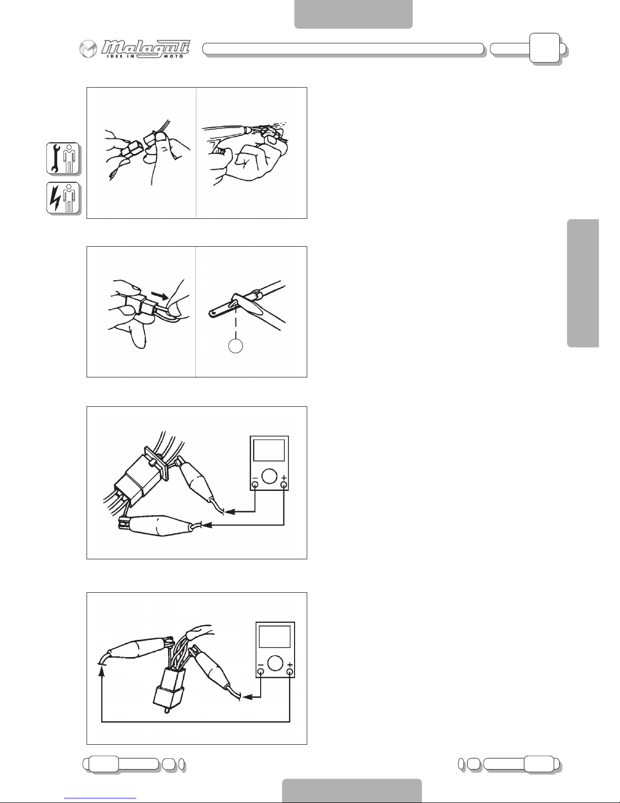
CHECKING CONNECTORS
Check connectors for corrosion and damp.
1. Disconnect
connectors
2. Dry terminals with compressed air .
3. Connect and disconnect connector two or
three times.
4. Pull connector to make sure it is correctly
plugged in.
5. If terminal comes loose, bend stop (A) and
refit terminal in connector.
6. Connect
connectors
NOTE:
The “click” sound means that all
connector parts are correctly assembled.
7. Check continuity with a Tester.
NOTE:
If there is no continuity, clean terminals.
Follow the instructions from step 1 to 7 to
check the electrical equipment.
As a temporary solution, use a contact
cleaner.
Use Tester as shown in the illustration.

B
12 08.06
CHAPTER
PAGE ISSUE
ELECTRIC SYSTEM TROUBLESHOOTING
ENGLISH
SECTION 2
Checking the Switches
SECTION 2
B - TROUBLESHOOTING
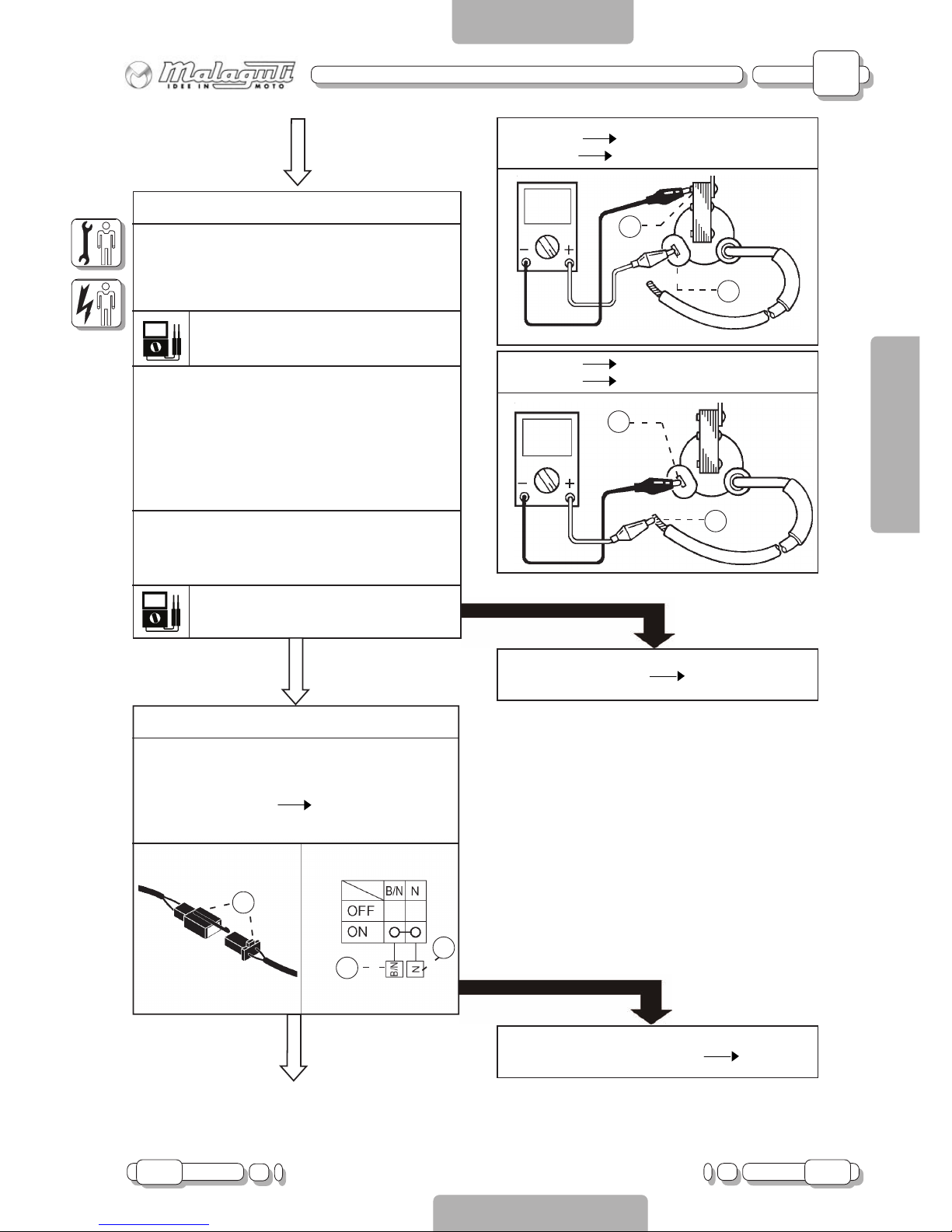
CHECKING SWITCHES
Use a Tester to check continuity between terminals
and make sure these are correctly connected. If one of
the combinations does not give the requested result,
replace the component.
NOTE:
Operate the “ON-OFF” switch several times.
Put T ester selector on “W”.
Put indicator on “0”.
CONNECTION OF THE SWITCHES
DESCRIBED IN THIS MANUAL
This manual contains connection diagrams, like the one
illustrated on the left, which illustrate how switch
terminals should be connected (key switch, brake
switch, light switch, etc.).
The column on the left indicates the different positions
of the switches; the first line indicates the colours of
the wires connected to the switch terminals.
“•” means that there is continuity between the terminals;
namely a closed circuit in a certain position of the switch.
In this example, there is continuity between “Br” and
“R” when the switch is “ON”.

B
08.06 13
CHAPTER
PAGEISSUE
ELECTRIC SYSTEM TROUBLESHOOTING
ENGLISH
SECTION 2
Ignition System
SECTION 2
B - TROUBLESHOOTING
M
BL
AR
BL
BB
N
M
VR
VL
AR
N
M
VR
VL
GR
N
K
A
B
R
+
-
N
LOCK
OFF
ON
VR
GR
VL
M-N
GL-R
GR-R
vuoto
vuoto
vuoto
1
18
LUCI
BL
VR-N
VR
GL
AR
VL-GL
RS
BL-R
BL-R
N
R
VL-GL
GL-R
B
BL-B
B-R
MODE
R
ENGINE
STOP
ON
OFF
ON
OFF
BL
R
10W
ID
SX
VL
10W
ID
DX
N
VR
35W
FARO
10W
ID
SX
N
VL
10W
ID
DX
N
VR
N
21W
STOP
5W
POS
RS
R
AR
HT
1
16
+
ON
OFF
HORN
GR
R
L
VL
M
VR
TURN
N
+
+
N
RS
F 10A
N
GL-R
Vuoto
BL
GR-R
GL-B
AR
B-R
Vuoto
BL-B
GL-VR
BL-N
M-N
RS-N
//
BL
R
R-N
N
GR
M-N
B-R
RS-N
B-R
BL-N
GL-VR
B-R
VL-GL
B
R
N
VL-GL
B
R
N
vuoto
vuoto
B-R
BL
VR/N
VR
GL
AR
vuoto
vuoto
R
B
N
B
BL-B
B-R
B-R
N
N
VL-GL
BL-R
B-N
N
VR-N
B-VR
N
GR
M
GR
VR-N
B-VR
B-N
N
BL
BL
BL
Vuoto
BL
B-GL
TPS
B-VL
R-N
B-VL
R-N
R-N
Vuoto
3
4
6
14
20
27
16
KEY TO IGNITION SYSTEM
3) CONTROL UNIT
4) FL YWHEEL MAGNETO
6) CHASSIS GROUNDING
14 ) KEY SWITCH
16) “ENGINE STOP” BUTTON
20) COIL
27 ) SIDE ST AND SWITCH

B
14 08.06
CHAPTER
PAGE ISSUE
ELECTRIC SYSTEM TROUBLESHOOTING
ENGLISH
SECTION 2
Ignition System
SECTION 2
B - TROUBLESHOOTING
TROUBLESHOOTING
THE IGNITION SYSTEM DOES NOT WORK
(NO SPARKING OR INTERMITTENT SP ARKING)
1. Spark plug
2. Spark plug cap resistance
3. HV coil resistance
4. “ENGINE STOP” button
5. Side stand switch
6. Key switch
7. Pick-up resistance
8. System connections
1. Spark plug
- Check condition of spark plug
- Check type of spark plug
Gap between electrodes:
0.7 mm
COMPLIANT
2. Spark plug cap resistance
- Remove spark plug cap
NOTE
Never pull spark plug cable to remove cap
- Connect the T ester (K
) as shown in the figure
T o remove, turn anti-clockwise
To connect, turn clockwise
- When connecting, check spark plug cable and
if necessary replace it with a new one.
Cap resistance:
5K
± 20% a 20°C
COMPLIANT
Sample spark plug:
NGK BR9ES
Spark plug not in working order Replace or
adjust gap between electrodes
NOT COMPLIANT
T erminal (+) Spark plug side (1)
T erminal (-) Spark plug cable side (2)
2
1
Faulty spark plug cap Replace
NOT COMPLIANT
B
08.06 15
CHAPTER
PAGEISSUE
ELECTRIC SYSTEM TROUBLESHOOTING
ENGLISH
SECTION 2
Ignition System
SECTION 2
B - TROUBLESHOOTING
3. HV coil resistance
- Disconnect orange cable
- Connect T ester “
” to HV coil
- Check resistance of coil’s primary winding
Primary winding resistance:
0,23
± 20% a 20°C
- Connect Tester “
” to HV coil
- Check resistance of coil’s secondary winding
Primary winding resistance:
7,9
± 20% a 20°C
COMPLIANT
1
2
3
4. “Engine Stop” button
- Disconnect four-way connector (1)
- Connect Tester “
” and check continuity
between cables
White-black cable (2) Black cable (3)
See “Checking connectors” on page 1 1
COMPLIANT
T erminal (+) T erminal (1)
T erminal (-) Grounded (2)
1
2
1
2
T erminal (+) Spark plug cable (1)
T erminal (-) T erminal (2)
NOT COMPLIANT
Faulty HV coil Replace
NOT COMPLIANT
Faulty “Engine Stop” button Replace

B
16 08.06
CHAPTER
PAGE ISSUE
ELECTRIC SYSTEM TROUBLESHOOTING
ENGLISH
SECTION 2
Ignition System
SECTION 2
B - TROUBLESHOOTING
5. Side stand switch
- Disconnect two-way connector (1) of side stand
- Connect T ester “
” to connector, as follows:
T erminal (+) T erminal (2)
T erminal (-) T erminal (3)
1
3
2
COMPLIANT
6. Key switch
- Disconnect connector (1) of key switch
- Turn key “ON”
- Connect Tester “
” and check continuity as
follows:
T erminal (+) Orange cable (2)
T erminal (-) Green cable (3)
See “Checking connectors” on page 1 1
1
2
3
COMPLIANT
NOT COMPLIANT
Faulty side stand switch Replace
NOT COMPLIANT
Faulty key switch Replace

B
08.06 17
CHAPTER
PAGEISSUE
ELECTRIC SYSTEM TROUBLESHOOTING
ENGLISH
SECTION 2
Ignition System
SECTION 2
B - TROUBLESHOOTING
7. Pick-up resistance
- Disconnect four-way connector (1) of flywheel
magneto (2)
- Connect T ester “
” to connector, as follows:
T erminal (+) White-Red T erminal (3)
T erminal (-) Blue-White T erminal (4)
- Check pick-up resistance
Pick-up resistance:
350
± 20% a 20°C
COMPLIANT
8. Connections
- Check connections of ignition system
See “Circuit Diagram”.
COMPLIANT
Replace “CDI” control unit
1
4
3
2
NOT COMPLIANT
Replace stator
NOT COMPLIANT
Resume system’s connections
 Loading...