

Page 1

Page 2

2
T A B L E O F C O N T E N T S
TABLE OF CONTENTS
Page
Introduction 3
Manual updates 3
Notes for easy consultation 4
Page layout 4
Modifi ed pages 4
Additional pages 4
Editing symbols 4
Abbreviations 6
Technical term dictionary 7
General wiring diagram 8
Key to general wiring diagram 9
Colour key 10
Instrument board connector confi guration 11
Continuity of contacts 12
Location of electrical components 13
Checking connectors 15
Checking switches 16
Connection of switches described in this manual 16
Checking fuses 17
Checking fuses 17
Ignition system 18
Faulty ignition 18
Page
Electrical starting system 22
Faulty electrical starting system 22
Recharging system 27
Battery cannot be charged 27
Lighting system 30
The entire lighting system does not work 30
The low beam light, high beam light and relative indicator lights do not come on
33
Rear light does not come on 35
Signalling system 36
Horn is not working 36
Stop light does not work 38
Turn indicators and relative indicator lights do not work 40
Right/left turn indicators do not work 42
Neutral indicator light does not come on 43
Display functions cannot be changed 44
Rev counter is not working 46
Reserve warning light does not come on 47
Heat sensor circuit system 49
General matters 49
Checking “PTC” heater circuit and heat sensor 49
Page 3
3
I N T R O D U C T I O N
INTRODUCTION
Malaguti reserves the right to make any and all changes to its vehicles as it deems fi t and appropriate at any time without prior notice.
No part of this publication, whether text or illustrations, may be reproduced or circulated either totally or partially. Malaguti reserves all rights over this publication.
Reasons must be given for any request for permission (written) thereto.
FIRST EDITION: 04/08
INTRODUCTION
This publication describes all necessary steps for troubleshooting concerning the electrical system (Electronic Injection System) and of the possible service operations,
which are necessary for their solution. It supplies the trade technicians (Authorised Service Centres) with the necessary information for operating in compliance with the
modern concepts of “good practice” and “safety at work”.
Further information can be derived from the “Chassis” workshop manual, from the “Engine” workshop manual and from the Spare Parts catalogue.
All described operations must be performed by technicians with the necessary skill and experience.
The steps for the removal of body parts and of electric and mechanical components, to allow access to wiring or electric components to service, can be taken from the
“Chassis” Workshop Manual.
We recommend you follow the information given in this publication with care.
For any further information you may need, refer to the Malaguti S.p.A. Technical Department.
It is essential to follow the instructions with great care. Work carried out carelessly or, worse still, work that has not been accomplished, can cause injuries and damage or,
in the less serious cases, tiresome complaints.
MANUAL UPDATES
Any subsequent updates applying to this Manual will be sent in a reasonable time.
The table of contents will be duly updated in the event that new pages are inserted, which render the consultation of the manual diffi cult.
The Electrical System Troubleshooting Manual is to be considered as an essential tool to be properly kept up-to-date so as to maintain its “validity”
over time.
•
•
•
•
•
•
•
•
•
•
•
Page 4
4
NUMERO DI PAGINA
TI T OL O S EZ IO NE
TITOLO SEZIONE
X
W
I N T R O D U C T I O N
INTRODUCTION
NOTES FOR EASY CONSULTATION
PAGE LAYOUT
MODIFIED PAGES
Modifi ed pages shall bear the same number as those in the previous edition, followed by the letter M, with the new date of issue appearing in the appropriate box.
Modifi ed pages may contain new illustrations; in this case, the added illustration (or illustrations) will bear the number of the illustration on the former page, followed by a
letter.
ADDITIONAL PAGES
Any additional pages shall bear the last number of the section to which they belong, followed by the letter A and the new date of issue.
EDITING SYMBOLS
Symbols have been provided for quick and easy reference (P. 5), identifying situations requiring utmost attention or providing practical suggestions or simple
information.
These symbols may appear next to a text (in which case they refer solely to the text itself), next to a fi gure (in which case they refer to the topic illustrated in the fi gure
and to the relative text), or at the top of the page (in which case they refer to all the topics dealt with in the page).
The meaning of the symbols should be duly memorised as their scope is to avoid having to repeat basic technical concepts or safety recommendations. They
are therefore to be considered as veritable “memory tags”. In case of any doubt as to their meaning, consult the Page in which they are fully described.
•
•
•
•
•
X
SECTION TITLE
W
PAGE NUMBER
Page 5
5
I N T R O D U C T I O N
INTRODUCTION
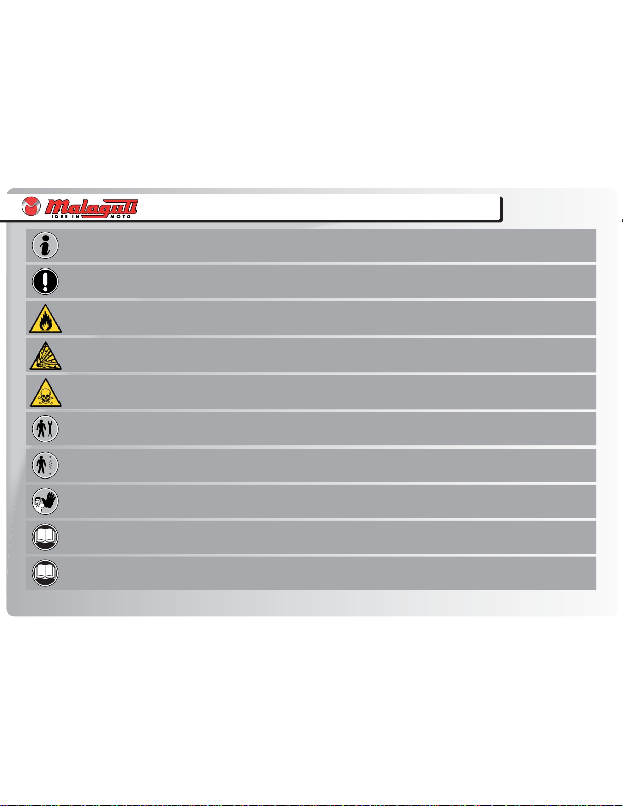
NOTE
Recommendations and precautions regarding rider safety and motor vehicle integrity.
CAUTION!
Situations entailing the risk of personal injury to maintenance or repair mechanics, other workshop personnel or third parties, or damage to environment,
vehicle or equipment.
FIRE HAZARD
Indicates operations which may constitute a fi re hazard.
DANGER OF EXPLOSION
Indicates operations which may constitute a risk of explosion.
TOXIC FUMES
Indicates a possibility of intoxication or infl ammation of the upper respiratory tract.
MECHANICAL MAINTENANCE
Operations to be performed only by an expert mechanic.
ELECTRICAL MAINTENANCE
Operations be performed only by an expert electrical/electronic technician.
NO!
Operations to be absolutely avoided.
M
ENGINE WORKSHOP MANUAL
Indicates information which may be obtained by referring to said document.
R
SPARE PARTS CATALOGUE
Indicates information which may be obtained by referring to said document.
Page 6
6
A
I N T R O D U C T I O N
INTRODUCTION
ABBREVIATIONS
F Figure
Cs Tightening torque
P Page
Pr Paragraph
S Section
Sc Diagram
T Table
V Screw
The letter V in the illustrations refers to retaining or adjusting screws.
The number following this letter refers to the number of the same type
of screw in the unit or component described and illustrated. Letters not
followed by a number indicate a single screw. In case of different
screws being referred to in the illustration, the letter V is followed by a
number and a small letter, for instance: (V4a).
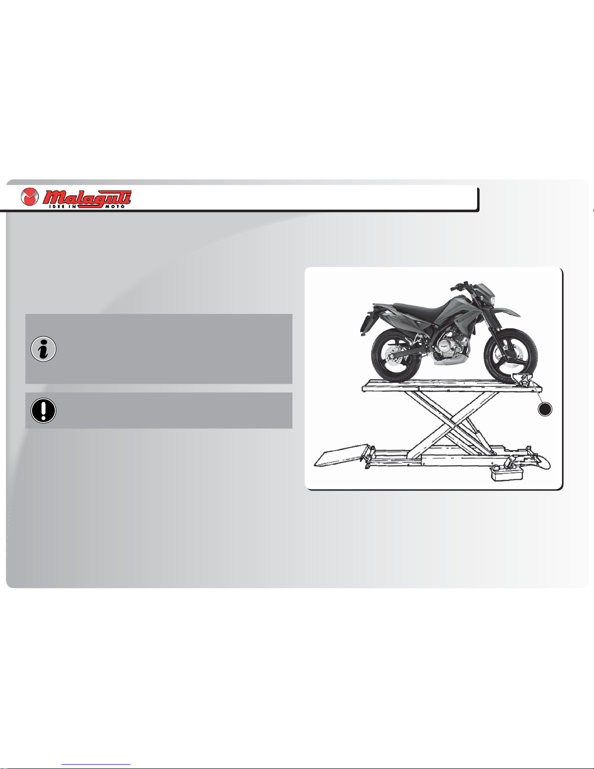
Unless otherwise specifi ed, units and components are reassembled by
proceeding in the reverse order of removal.
Before any servicing, make sure that the vehicle is perfectly
stable.
The front wheel should preferably be anchored to the equipment
integral with the lifting board (A).
•
•
•
•
•
•
•
•
Page 7
7
I N T R O D U C T I O N
INTRODUCTION
TECHNICAL TERM DICTIONARY
V = (DC) : direct current (supply from battery)
V ~ (AC) : alternating current (supply from fl ywheel)
A: Ampere: the unit of electric current
W: Watt: the unit of electric power
(result of Volts by Amps A x V = W)
: OHM: the unit of electrical resistance
Infi nite OHM: tester prods disconnected or cable interrupted
OHM = 0: continuity with tester prods connected and cable not interrupted
PIN: connector terminal
Line: cable between two PINS
< : less than
<: less than or equal to
> : greater than
> : greater than or equal to
KPa (or bar): the unit of pressure (100 KPa = 1 bar)
÷ : from - to
~ : approximately
•
•
•
•
•
•
•
•
•
•
•
•
•
•
•
•
Page 8
8
4
3
2
1
41 40 33353739 34 32 29 2728
26
25
24
23
21191816159 131110
5
7
8
12 14 17 20
36
6
38 30
31
22
G E N E R A L W I R I N G D I A G R A M
GENERAL WIRING DIAGRAM
Page 9

9
G E N E R A L W I R I N G D I A G R A M
GENERAL WIRING DIAGRAM
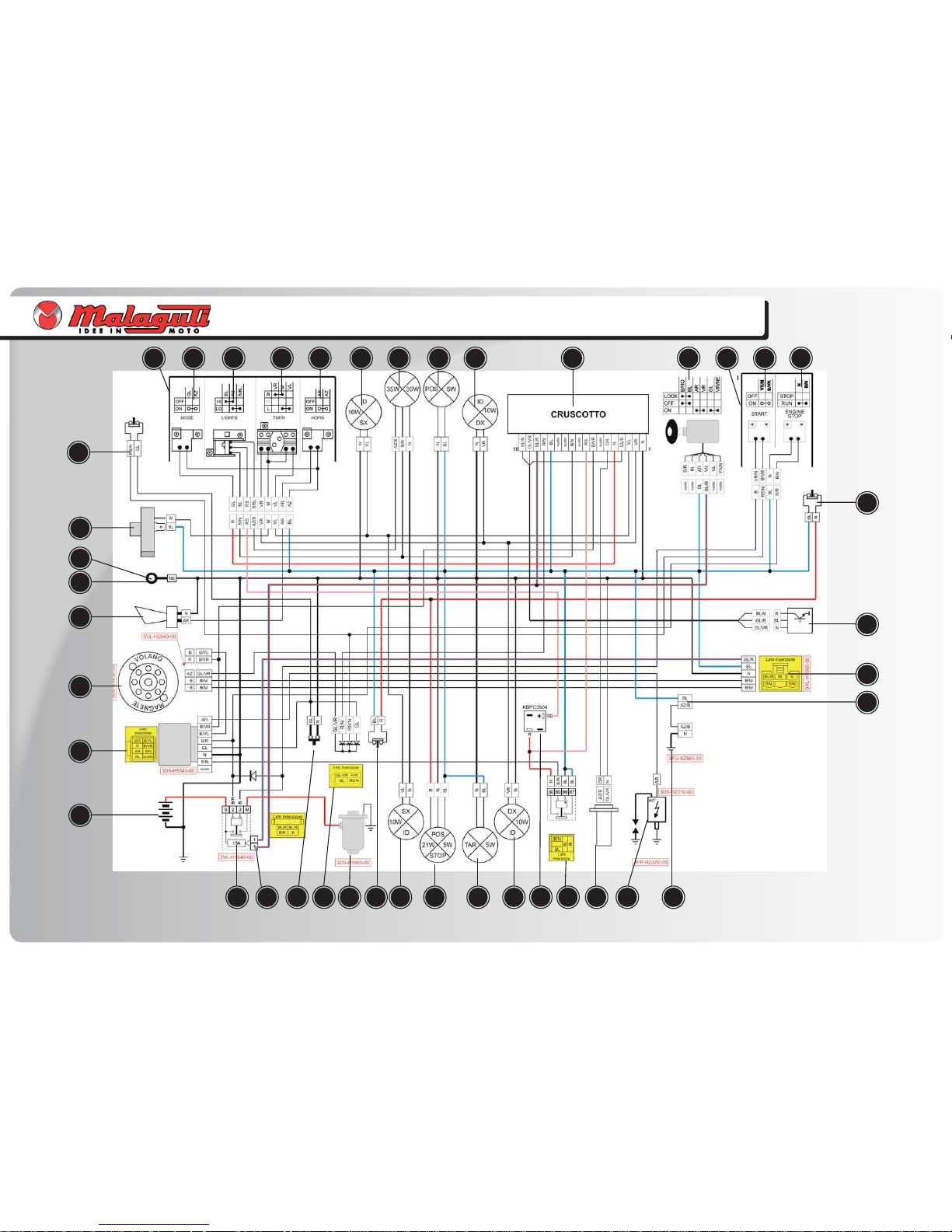
KEY TO GENERAL WIRING DIAGRAM
1) BATTERY
2) “CDI” CONTROL UNIT
3) FLYWHEEL MAGNETO
4) HORN
5) CHASSIS GROUND CONNECTION
6) REGULATOR GROUND CONNECTION
7) FLASHLIGHT
8) CLUTCH SWITCH
9) LEFT HAND CONTROL UNIT
10) “MODE” BUTTON
11) LIGHT CONTROL
12) TURN INDICATOR CONTROL
13) HORN CONTROL
14) FRONT LEFT TURN INDICATOR
15) LOW BEAM / HIGH BEAM LIGHT
16) PARKING LIGHT
17) FRONT RIGHT TURN INDICATOR
18) INSTRUMENT BOARD
19) KEY SWITCH
20) RIGHT HAND CONTROL UNIT
21) START BUTTON
22) “ENGINE STOP” BUTTON
23) FRONT STOP SWITCH
24) SPEEDOMETER SENSOR
25) REGULATOR
26) HEAT SENSOR
27) “PTC” FUEL HEATER
28) COIL
29) FUEL RESERVE SENSOR
30) LIGHT RELAY
31) DIODE BRIDGE
32) REAR RIGHT TURN INDICATOR
33) NUMBER PLATE LIGHT
34) TAIL AND STOP LIGHT
35) REAR LEFT TURN INDICATOR
36) REAR STOP SWITCH
37) STARTER MOTOR
38) DIODE SET
39) SIDE STAND SWITCH
40) STARTER RELAY
41) FUSE, 15 A
Page 10

10
G E N E R A L W I R I N G D I A G R A M
GENERAL WIRING DIAGRAM
COLOUR KEY
AR ORANGE
AZ LIGHT BLUE
AZ-B LIGHT BLUE - WHITE
AZ-GR LIGHT - BLUE GREY
B WHITE
B-N WHITE - BLACK
B-VR WHITE - GREEN
B-M WHITE - BROWN
B-R WHITE - RED
B-VL WHITE - PURPLE
BL BLUE
BL-B BLUE - WHITE
BL-GL BLUE - YELLOW
BL-N BLUE - BLACK
BL-R BLUE - RED
GL YELLOW
GL-B YELLOW - WHITE
GL-N YELLOW - BLACK
GL-VR YELLOW - GREEN
GL-R YELLOW - RED
GR GREY
GR-R GREY - RED
M BROWN
M-N BROWN - BLACK
N BLACK
R RED
RS PINK
VL PURPLE
VR GREEN
VR-GL PURPLE - YELLOW
VR-N GREEN - BLACK
R-N RED - BLACK
RS-N PINK - BLACK
Page 11

11
G E N E R A L W I R I N G D I A G R A M
GENERAL WIRING DIAGRAM
INSTRUMENT BOARD CONNECTOR CONFIGURATION
PIN CABLE COLOUR FUNCTION PIN CABLE COLOUR FUNCTION
1N NEGATIVE (-) 10 - -
2VRRIGHT HAND TURN INDICATOR 11 B-N HIGH BEAM LIGHT
3VLLEFT HAND TURN INDICATOR 12 - -
4 GL-R HALL SENSOR INPUT 13 - -
5R MODE BUTTON SIGNAL 14 BL + 12 V WITH KEY ON
6GR FUEL WARNING LIGHT 15 R-N NEUTRAL WARNING LIGHT
7- - 16 BL-R +12 V WITH KEY OFF
8 B-VR RPM 17 GL-VR HALL SENSOR CDD
9RS PARKING LIGHTS 18 BL-N HALL SENSOR VDC
Page 12
12
6
10
7
8
4
3
2
1
1 42 3
5
6
107 8 9
5
9
11
11
CLOSE
OPEN
C H E C K I N G S W I T C H E S
CHECKING SWITCHES
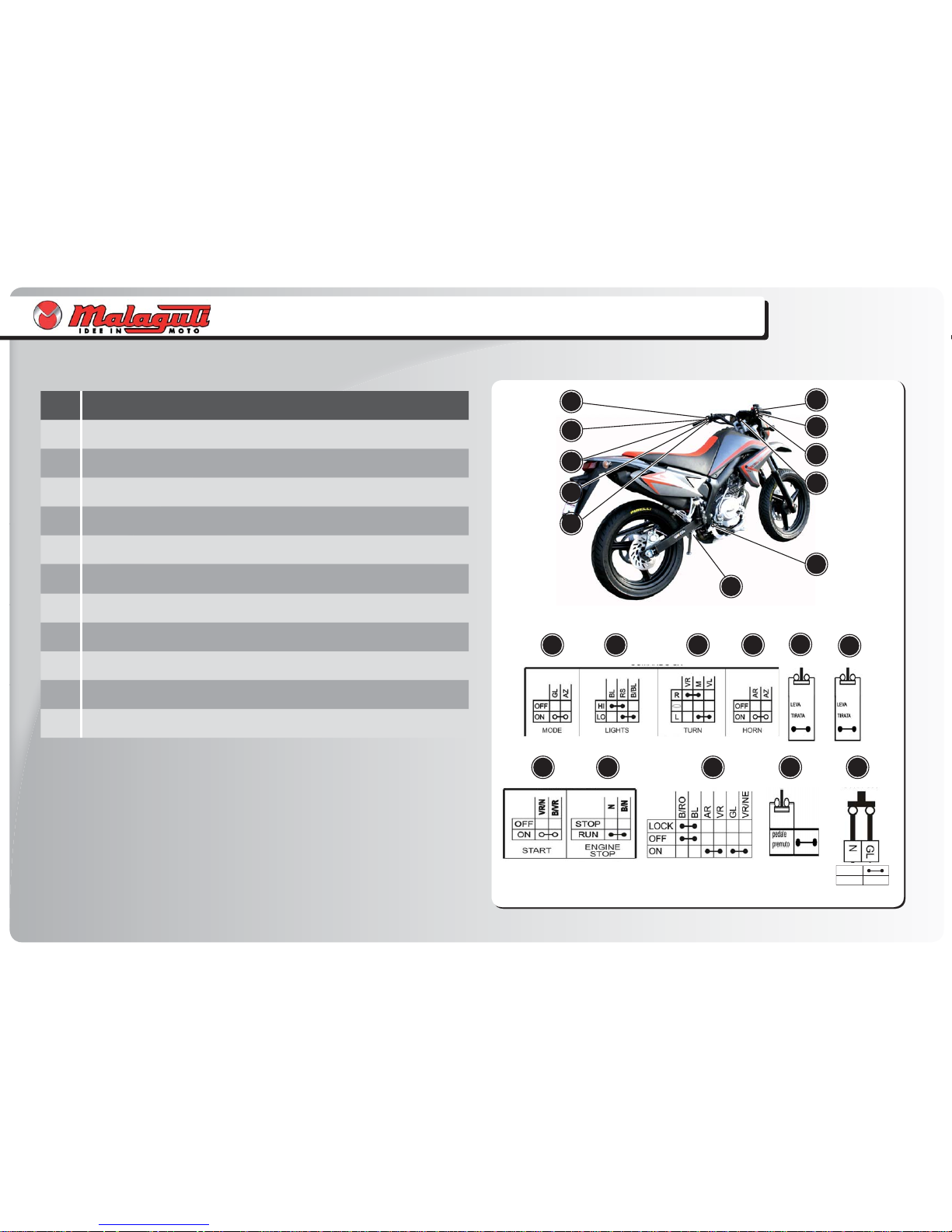
CONTINUITY OF CONTACTS
POS. SWITCHES
1 MODE BUTTON
2 LIGHT SWITCH
3 TURN INDICATOR SWITCH
4 HORN CONTROL
5 CLUTCH SWITCH
6 FRONT STOP SWITCH
7 ENGINE START SWITCH
8 ENGINE STOP SWITCH
9 KEY SWITCH
10 REAR STOP SWITCH
11 SIDE STAND SWITCH
Page 13
13
1
2
3
4
5
6
9
3
4
2
5
8
6
7
8
9
10
11
1
10
11
7
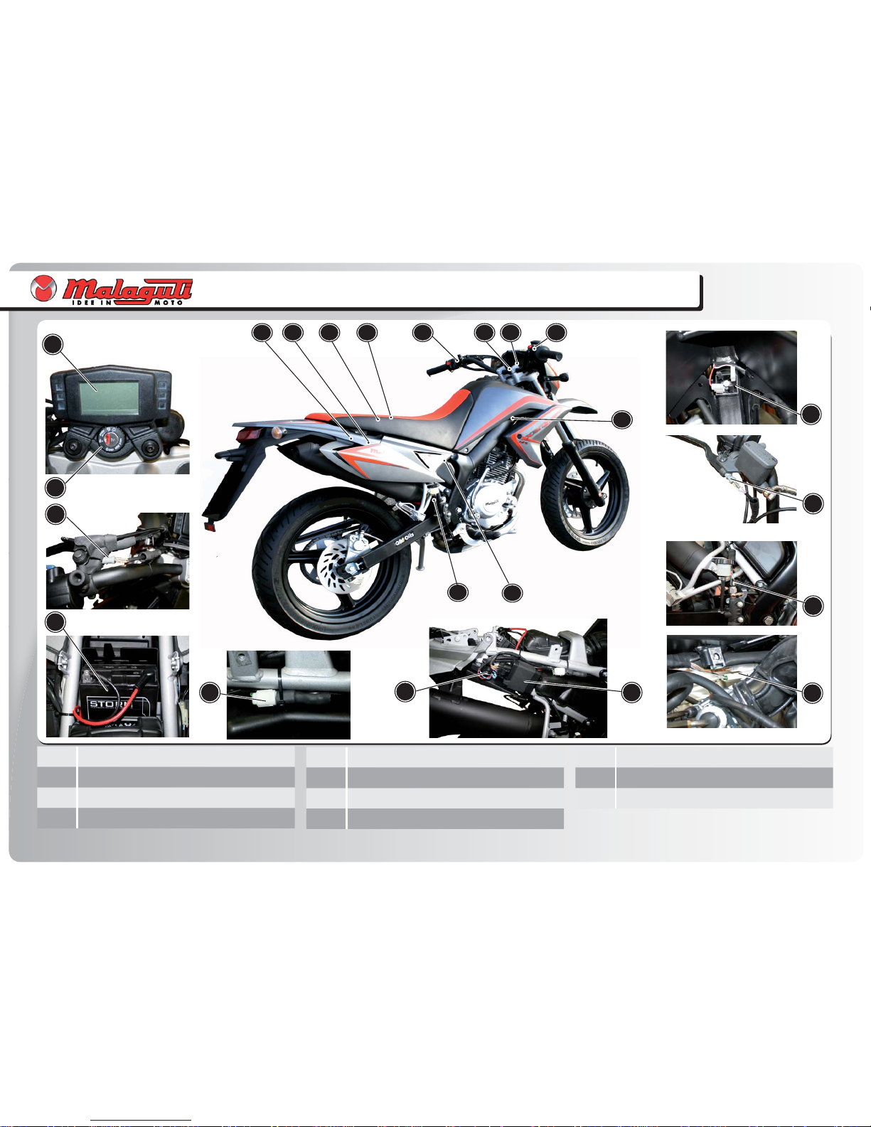
L O C A T I O N O F E L E C T R I C A L C O M P O N E N T S
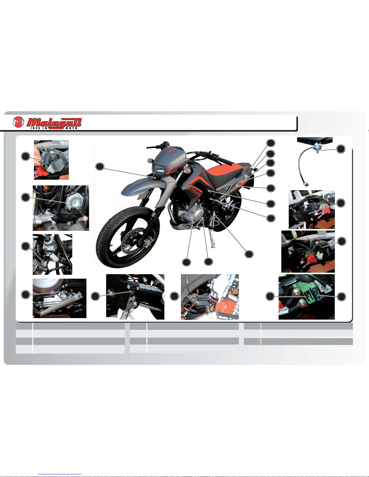
LOCATION OF ELECTRICAL COMPONENTS
1 Thermal switch
2 Horn
3 “PTC” fuel heater
4 Neutral switch
5 Side stand switch
6 HV coil
7 Starter relay
8 Fuse 15 A
9 Flashlight
10 Regulator
11 Fuel probe
Page 14
14
131415
21
12
13
17
18
19
20
16
15
161718
19
21
22
2012
22
14
L O C A T I O N O F E L E C T R I C A L C O M P O N E N T S
LOCATION OF ELECTRICAL COMPONENTS
12 Digital instrument board
13 Key switch
14 Clutch switch
15 Battery
16 Diode set
17 Light relay
18 CDI control unit
19 Diode bridge
20 Front stop switch
21 Rear stop switch
22 Stator connectors
Page 15
15
C H E C K I N G C O N N E C T O R S
CHECKING CONNECTORS
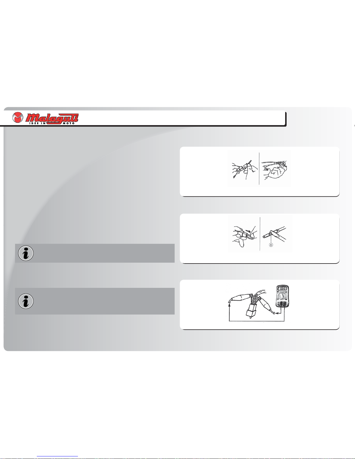
CHECKING CONNECTORS
Check connectors for corrosion and damp.
Disconnect connectors.
Dry terminals with compressed air.
Connect and disconnect connector two or three times.
Pull connector to make sure it is correctly plugged in.
If terminal is disconnected, bend stop (A) and refi t terminal in connector.
The “click” sound means that all connector parts are correctly
assembled.
Plug in connectors.
Check continuity (Tester ).
If there is no continuity, clean terminals.
As a temporary solution, use a contact cleaner.
Follow the instructions provided above to check the electrical
equipment.
Use Tester as shown in the illustration
•
•
•
•
•
•
•
•
Page 16

16
C H E C K I N G S W I T C H E S
CHECKING SWITCHES
CHECKING SWITCHES
CHECKING PROCEDURES
Using a tester (Code n°08611200), check the switches by making sure that there is
continuity between terminals and that they are correctly connected.
Replace the switch, even if only one of the possible combinations does not give the
requested result.
Select “Ω” (ohm) function of tester; sound-emitting function.
Using the tester in “” mode, you can also check integrity of the lamps.
CONNECTION OF THE SWITCHES DESCRIBED IN THIS MANUAL
This manual contains connection diagrams, like the one illustrated hereby, which
illustrate how switch terminals should be connected (key switch, brake switch,
MODE button, etc.).
The fi rst column from the left indicates the different positions of the switches; the
top line indicates the colour of the wires connected to the switch terminals.
The “ ” symbol identifi es terminals in which there is a condition of continuity, i.e.
a closed circuit, in a certain position of the switch.
In this diagram:
“BL-B” and “R”: there is continuous contact when the switch is “ON”.
•
•
•
•
Page 17

17
F. 1
F. 2
C H E C K I N G F U S E S
CHECKING FUSES
CHECKING FUSES
When checking or replacing fuses, always turn the main switch
“OFF” or short-circuits may occur.
Checking procedure:
Connect Tester (code n°08611200) to fuse and check continuity.
Put the Tester on “Ω” (sound-emitting function).
If the tester is showing “I” and no sound is given, replace the fuse.
Replacing procedure:
Turn key “OFF”.
Fit a new fuse with a correct amperage rating.
Turn key “ON”
Turn all switches on to check operation of the relative electrical systems.
If the fuse blows again, check the relative circuit.
Never use fuses with an amperage rating differing from that
indicated. Use only fuses and never other materials. An unsuitable
fuse can cause extensive damage to the electrical system,
malfunctioning of the ignition and light systems and even fi res
to break out.
•
•
•
•
•
•
•
Page 18

18
NO
OK
OK
NO
2
2
1
Tester ()
F. 3
F. 4
1
I G N I T I O N S Y S T E M
IGNITION SYSTEM
FAULTY IGNITION
Check:
1. Fuse, 15 A
2. Battery
3. Spark plug
4. Spark plug cap resistance
5. HV coil resistance
6. Key switch
7. Pick-up resistance
8. Ignition system connections
1. Fuse 15 A
Remove relative fuse.
Connect Tester () to fuse.
Check continuity of fuse.
•
•
•
Eliminate short-circuit.
Replace fuse.
•
•
2. Battery
Check condition of battery:
Terminal (+) of Tester Battery (+) pole (1).
Terminal (-) of Tester Battery (-) pole (2).
If voltage level is lower than 12.4 V, recharge using a suitable battery charger.
After charging the battery, do not use it for approximately 30 minutes; now measure voltage level again.
12.8 V or more Battery is charged.
12,5 V Battery needs to be recharged.
12,0 V or less Replace battery.
Density of electrolytic solution: 1280 g/dm3.
•
•
•
•
•
•
•
•
•
Clean terminals.
Top up with distilled water.
Recharge or replace battery.
•
•
•
Page 19

19
NO
OK
NO
OK
Tester ()
2
1
OK
F. 5
I G N I T I O N S Y S T E M
IGNITION SYSTEM
3. Spark plug
Check condition of spark plug.
Check type of spark plug.
Check gap between electrodes.
•
•
•
Gap between electrodes: 0.7 mm.•
Replace spark plug:
NGK CR7HSA or DENSO U22 FSR-U.
4. Spark plug cap resistance
Remove spark plug cap.
To remove, turn anti-clockwise.
To connect, turn clockwise.
•
•
•
Connect tester ().
Terminal (+) of Tester Spark plug cable side (1).
Terminal (-) of Tester Spark plug side (2).
When connecting, check spark plug cable and if necessary replace it with a new one.
•
•
•
•
Spark plug cap resistance: 5k ± 20% at 20°C.•
Replace spark plug cap.
Page 20

20
NO
OK
NO
OK
5
6
Tester ()
OK
Tester ()
1
2
Tester k
1
3
Tester
F. 6
F. 7
F. 8
I G N I T I O N S Y S T E M
IGNITION SYSTEM
5. HV coil resistance
Disconnect orange cable.
Connect Tester () to HV coil.
Check resistance of coil’s primary winding: 0.9 ± 10% at 20°C.
Terminal (+) of Tester Terminal (1).
Terminal (-) of Tester Ground (2).
•
•
•
•
•
Check resistance of coil’s secondary winding: 7.30 K ± 10% at 20°C.
Terminal (+) of Tester Terminal (1).
Terminal (-) of Tester Spark plug cable (3).
•
•
•
Replace ignition coil.
6. Key switch
Disconnect key switch from system.
Turn key “ON”.
•
•
Connect Tester () and check continuity of key switch as follows:
Terminal (+) of Tester Orange cable (5).
Terminal (-) of Tester Green cable (6).
•
•
•
Replace key switch.
Page 21

21
NO
OK
NO
OK
2
Tester ()
1
OK
F. 9
I G N I T I O N S Y S T E M
IGNITION SYSTEM
7. Pick-up resistance
Disconnect two-way connector of fl ywheel magneto.
Connect Tester () to connector as follows:
Terminal (+) of Tester Red terminal (1).
Terminal (-) of Tester White terminal (2).
•
•
•
•
Check pick-up resistance: 240 ± 10% at 20°C.•
Replace stator.
8. Connections
Check connections of ignition system.
See “Wiring Diagram”.
•
•
Resume system’s connections.Replace “CDI” control unit.
Page 22

22
NO
OK
NO
OK
2
1
Tester ()
2
F. 11
1
F.10
F. 11
E L E C T R I C A L S T A R T I N G S Y S T E M
ELECTRICAL STARTING SYSTEM
FAULTY ELECTRICAL STARTING SYSTEM
Check:
1. Fuse, 15 A
2. Battery
3. Starter motor
4. Starter relay
5. Key switch
6. Neutral switch
7. Clutch switch
8. Start button
9. “Engine stop” button
10. Side stand switch
11. Connections
1. Fuse, 15 A
Remove relative fuse.
Connect Tester () to fuse.
Check continuity of fuse.
•
•
•
Eliminate short-circuit.
Replace fuse.
•
•
2. Battery
Check condition of battery.
Connect Tester (V) as follows:
Terminal (+) of Tester Battery positive (1).
Terminal (-) of Tester Battery negative (2).
Minimum voltage: 12.5 V.
Density of electrolytic solution: 1280 g/dm3.
Level of electrolytic solution.
•
•
•
•
•
•
•
Page 23

23
BATTERIA
BATTERIA
+
-
N
12 V
NO
OK
NO
OK
NO
OK
Tester ()
BATTERIA
BATTERIA
+
-
N
12 V
2
1
3
4
M
B
F. 12
F. 13
E L E C T R I C A L S T A R T I N G S Y S T E M
ELECTRICAL STARTING SYSTEM
Clean terminals.
Top up with distilled water.
Recharge or replace battery.
•
•
•
3. Starter motor
Connect a 12 V battery to starter motor:
Battery (+) pole Terminal (+) of starter motor (1).
Battery (-) pole Terminal (-) of starter motor (2).
•
•
•
Check operation of the starter motor.•
To connect, use cables that are compatible with the power draw of the starter motor.
Replace starter motor.
4. Starter relay
Disconnect starter relay.
Connect a 12 V battery to the starter relay:
Battery (+) pole Terminal (3).
Battery (-) pole Terminal (4).
•
•
•
•
Connect tester () to terminals (B) and (M) of starter relay.
Check continuity.
•
•
B: Battery cable Starter relay.
M: Starter relay cable Starter motor.
Replace starter relay.
Page 24

24
NO
OK
NO
OK
Tester ()
4
3
1
2
Tester ()
OK
F. 15
F. 14
E L E C T R I C A L S T A R T I N G S Y S T E M
ELECTRICAL STARTING SYSTEM
5. Key switch
Disconnect key switch.
Turn key “ON”.
Connect Tester () as follows:
Terminal (+) of Tester Orange cable (1).
Terminal (-) of Tester Green cable (2).
Check continuity.
•
•
•
•
•
•
Replace key switch.
6. Neutral switch
Connect Tester () as follows.
Terminal (+) of Tester Neutral switch (3).
Terminal (-) of Tester Chassis grounding (4).
Check continuity:
Transmission in neutral Continuity.
Vehicle in gear No continuity.
•
•
•
•
•
•
Replace neutral switch.
Page 25

25
NO
OK
NO
OK
1
Tester ()
3 4
2
OK
F. 16
F. 17
E L E C T R I C A L S T A R T I N G S Y S T E M
ELECTRICAL STARTING SYSTEM
7. Clutch switch
Disconnect clutch switch (1).
Connect Tester () as follows.
Terminal (+) of Tester T1 clutch switch.
Terminal (-) of Tester T2 clutch switch.
Check continuity between terminals.
Clutch lever not pulled (1) No continuity.
Clutch lever pulled (2) Continuity.
•
•
•
•
•
•
•
Replace clutch switch.
8. Start button
SDisconnect four-way connector (2).
Connect Tester () as follows.
Terminal (+) of Tester White/black cable (2).
Terminal (-) of Tester White - green cable (4).
Check continuity between terminals.
•
•
•
•
•
Replace right hand switch.
Page 26

26
NO
OK
NO
OK
NO
Tester ()
4
5 6
Tester ()
3 2
1
OK
CLOSE
OPEN
F. 18
F. 19
E L E C T R I C A L S T A R T I N G S Y S T E M
ELECTRICAL STARTING SYSTEM
9. “Engine stop” button
Disconnect four-way connector of right hand switch (1) .
Connect Tester () as follows.
Terminal (+) of Tester White/black cable (2).
Terminal (-) of Tester Black cable (3).
Check continuity between terminals.
•
•
•
•
•
Replace right hand switch
10. Side stand switch
Disconnect two-way connector (4).
Connect Tester () as follows.
Terminal (+) of Tester Terminal (5).
Terminal (-) of Tester Terminal (6).
Check continuity between terminals.
•
•
•
•
•
Replace side stand switch.
11. Connections
Check connections of starting system.
See “Circuit Diagram”.
•
•
Resume connections.
Page 27

27
NO
OK
2
1
Tester ()
F. 20
R E C H A R G I N G S Y S T E M
RECHARGING SYSTEM
BATTERY CANNOT BE CHARGED
Check:
1. Fuse, 15 A
2. Battery
3. Recharging voltage
4. Resistance of recharging coil
5. Starter relay
6. Connection of recharging system
1. Fuse, 15 A
Remove relative fuse.
Connect Tester () to fuse.
Check continuity of fuse.
•
•
•
Eliminate short-circuit.
Replace fuse.
•
•
Clean terminals.
Top up with distilled water.
Recharge or replace battery.
•
•
•
NO
OK
2. Battery
Check condition of battery.
Connect Tester (20 V DC) as follows:
Terminal (+) of Tester Battery positive.
Terminal (-) of Tester Battery negative.
Minimum voltage: 12.5 V.
Density of electrolytic solution: 1280 g/dm3.
Level of electrolytic solution.
•
•
•
•
•
•
•
Page 28

28
NO
OK
Tester ()
NO
OK
3
4
OK
2
F. 111 F. 21
F. 22
R E C H A R G I N G S Y S T E M
RECHARGING SYSTEM
3. Recharging voltage
Connect Tester (20 V DC) as follows:
Terminal (+) of Tester Battery positive (1).
Terminal (-) of Tester Battery negative (2).
Run engine at ~ 5000 RPM.
Check battery voltage.
Battery charging voltage: 12.5 ÷ 14.5 V.
•
•
•
•
•
•
Use a fully charged battery.
Recharging circuit is in working order.
4. Charging coil resistance
Disconnect three-way connector of fl ywheel magneto.
Connect Tester (200) as follows:
Terminal (+) of Tester White cable (3).
Terminal (-) of Tester White cable (4).
•
•
•
•
Measure resistance of charging coil: 1.20 ± 10% at 20°C.•
Replace stator.
Page 29

29
NO
OK
NO
OK
B
3
B
4
12
OK
Tester ()
F. 23
F. 24
R E C H A R G I N G S Y S T E M
RECHARGING SYSTEM
5. Starter relay
Test A.
Remove starter relay.
Connect Tester () as follows:
Terminal (+) of Tester Terminal (1).
Terminal (-) of Tester Terminal (2).
•
•
•
•
•
Check continuity.•
This check must be performed with the 15 A fuse inserted
Test B.
Connect Tester () as follows:
Terminal (+) of Tester Pole (B).
Terminal (-) of Tester Terminal (3).
Terminal (-) of Tester Terminal (4).
During both tests a condition of continuity must be recorded.
•
•
•
•
•
•
Replace starter relay.
6. Recharging system connections
Check connections of recharging system.
See “Wiring Diagram”.
•
•
Resume system’s connections.
Replace voltage regulator.
Page 30

30
NO
OK
NO
OK
2
1
Tester ()
2
F. 26
1
F. 25
L I G H T I N G S Y S T E M
LIGHTING SYSTEM
THE ENTIRE LIGHTING SYSTEM DOES NOT WORK
Check:
1. Fuse, 15 A
2. Battery
3. Key switch
4. Light relay
5. Connection to lighting system
1. Fuse, 15 A
Remove relative fuse.
Connect Tester () to fuse.
Check continuity of fuse.
•
•
•
Eliminate short-circuit.
Replace fuse.
•
•
2. Batteria
Check condition of battery.
Connect Tester (V) as follows:
Terminal (+) of Tester Battery positive (1).
Terminal (-) of Tester Battery negative (2).
Minimum voltage: 12.5 V.
Density of electrolytic solution: 1280 g/dm3.
Level of electrolytic solution.
•
•
•
•
•
•
•
Clean terminals.
Top up with distilled water.
Recharge or replace battery.
•
•
•
Page 31

31
NO
OK
NO
OK
BATTERIA
BATTERIA
+
-
N
12 V
Tester ()
86 85
87
30
Tester ()
2
1
OK
F. 28
F. 27
L I G H T I N G S Y S T E M
LIGHTING SYSTEM
3. Key switch
Disconnect key switch.
Turn key “ON”.
Connect Tester () as follows:
Terminal (+) of Tester Orange cable (1).
Terminal (-) of Tester Green cable (2).
Check continuity.
•
•
•
•
•
•
Replace key switch.
4. Light relay
Disconnect light relay.
Connect Tester () and battery (12V) to relay terminals, as follows:
Terminal (+) of battery Terminal (86).
Terminal (-) of battery Terminal (85).
Terminal (+) of Tester Terminal (87).
Terminal (-) of Tester Terminal (30).
Check continuity.
•
•
•
•
•
•
•
Never invert battery connections on relay terminals.
Replace light relay.
Page 32

32
NO
OK
OK
OK
1
2
F. 29
L I G H T I N G S Y S T E M
LIGHTING SYSTEM
5. Connection of lighting system
Check all connections of lighting system.
See “Wiring Diagram”.
•
•
Resume system’s connections.
Make sure that connection of pink (1) and red (2) cables
to diode bridge is correct (see photo).
”Replace the C.D.I. control unit
Page 33

33
NO
OK
NO
OK
Tester (DC 20 V)
A B
C
1
2
2
3
F. 31
F. 30
L I G H T I N G S Y S T E M
LIGHTING SYSTEM
THE LOW BEAM LIGHT, HIGH BEAM LIGHT AND RELATIVE INDICATOR LIGHTS DO NOT COME ON
Check:
1. Light bulb and relative coupling
2. Voltage level of lamp socket and instrument board
3. Left hand light switch (3)
1. Light bulb and relative coupling
Check continuity of light bulb and its coupling.•
Replace light bulb or coupling.
2. Check voltage level of lamp socket and instrument board
Connect Tester (20 V DC) to headlight and instrument board connectors.
Test A.
Check low beam light.
Terminal (+) of Tester Light blue - white cable (1).
Terminal (-) of Tester Black cable (2).
Test B.
Check high beam light.
Terminal (+) of Tester White - black cable (3).
Terminal (-) of Tester Black cable (2).
Test C.
Check high beam and lights indicator light.
Terminal (+) of Tester White - Black cable (PIN 11).
Terminal (+) of Tester Pink cable (PIN 9).
Terminal (-) of Tester Black cable (PIN 1).
Run the engine and press the button to turn on the low beam/high beam lights.
Voltage recorded during tests (A-B-C) must be > 12V.
•
•
•
•
•
•
•
•
•
•
•
•
•
•
•
•
Circuit is in working order.
Page 34

34
NO
OK
NO
L I G H T I N G S Y S T E M
LIGHTING SYSTEM
3. Light switch
Check continuity of light switch (see Checking switches on P.16).•
Replace left hand switchRepair wiring of headlight and/or instrument
board.
See “Wiring Diagram”.
•
•
Page 35

35
Tester (DC 20 V)
NO
OK
NO
OK
2
1
F. 32
L I G H T I N G S Y S T E M
LIGHTING SYSTEM
REAR LIGHT DOES NOT COME ON
Check:
1. Light bulb and relative coupling
2. Voltage level of lamp socket
1. Light bulb and relative coupling
Check continuity of light bulb and its coupling.•
Replace light bulb or coupling.
2. Check voltage level of lamp socket
Connect Tester (20 V DC) to terminals of light bulb coupling, as follows:
Terminal (+) of Tester Blue cable (1).
Terminal (-) of Tester Black cable (2).
Turn key “ON”.
Power measured must be > 12 V.
•
•
•
•
•
Resume connections between key switch and tail
lamp.
See “Wiring diagram” (P.8).
•
•
Circuit is in working order.
Page 36

36
Tester ()
1
2
3
Tester (DC 20 V)
4
5
NO
OK
NO
OK
F. 34
F. 33
S I G N A L L I N G S Y S T E M
SIGNALLING SYSTEM
HORN IS NOT WORKING
Check:
1. Light bulb and relative coupling
2. Voltage level
3. Ground connection
1. Horn switch
Disconnect nine-way connector of left hand switch (1).
Connect Tester () as follows:
Terminal (+) of Tester Orange cable (2).
Terminal (-) of Tester Light blue cable (3).
Press Horn button to activate horn.
Check continuity as follows:
Button pressed Continuity.
Button not pressed No continuity.
•
•
•
•
•
•
•
•
Replace left hand switch
2. Check voltage level
Connect Tester (20 V DC) as follows:
Terminal (+) of Tester Orange cable (4).
Terminal (-) of Tester Chassis grounding (5).
Turn key “ON”.
Press Horn button to activate horn.
Power measured must be > 12 V.
•
•
•
•
•
•
Repair power supply line of horn (orange cable).
See “Wiring diagram” (P.8).
•
•
If there is no power entering switch (blue cable),
the Mode button will not work (see point 2 on
P.44).
Page 37

37
NO
OK
2
3
4
1
OK
F. 35
S I G N A L L I N G S Y S T E M
SIGNALLING SYSTEM
3. Check ground connection
Disconnect black cable from terminal on horn (1).
Using a bridge cable (2), connect horn terminal (3) to chassis ground connection (4).
Turn key “ON”.
Press Horn button to activate horn.
Check operation of horn.
•
•
•
•
•
Replace horn.
Resume connection between black cable and chassis
ground connection.
See “Wiring Diagram” .
Page 38

38
Tester ()
4
3
NO
OK
NO
OK
1
2
F. 37
F. 36
S I G N A L L I N G S Y S T E M
SIGNALLING SYSTEM
STOP LIGHT DOES WORK
Check:
1. Light bulb and relative coupling
2. Brake switch
3. Voltage level
1. Light bulb and relative coupling
Check continuity of light bulb and its coupling.•
Replace light bulb or coupling.
2. Front and rear brake switch
Disconnect switch cables.
Connect Tester () as follows:
Terminal (+) of Tester Terminal (3).
Terminal (-) of Tester Terminal (4).
Check continuity of front brake (1) as follows:
Front brake lever pulled Continuity.
Front brake lever not pulled No continuity.
Check continuity of rear brake (2) as follows:
Rear brake pedal pressed Continuity.
Rear brake pedal not pressed No continuity.
•
•
•
•
•
•
•
•
•
•
Replace front and/or rear stop switch.
Page 39

39
Tester (DC 20 V)
2
1
NO
OK
OK
F. 38
S I G N A L L I N G S Y S T E M
SIGNALLING SYSTEM
3. Check voltage level
Connect Tester (20 V DC) as follows:
Terminal (+) of Tester Red cable (1).
Terminal (-) of Tester Black cable (2).
Turn key “ON”.
Pull brake lever or press brake pedal.
Power measured must be > 12 V.
•
•
•
•
•
•
Red cable is interrupted: resume connection.
See “Wiring diagram” (P.8).
•
•
Circuit is in working order.
If black cable (ground) is interrupted,
the tail lamp will not work.
Page 40

40
Tester ()
1
3
2
NO
OK
F. 39
S I G N A L L I N G S Y S T E M
SIGNALLING SYSTEM
TURN INDICATORS AND RELATIVE INDICATOR LIGHT DO NOT WORK
Check:
1. Turn indicator switch
2. Voltage level of fl ashlight
3. Continuity of brown cable
1. Turn indicator switch
Disconnect nine-way cable of left hand switch.
Flick switch to activate right hand turn indicators.
Connect Tester () as follows:
Terminal (+) of Tester Brown cable (1).
Terminal (-) of Tester Green cable (2).
Check continuity.
Flick switch to activate left hand turn indicators.
Connect Tester () as follows:
Terminal (+) of Tester Brown cable (1).
Terminal (-) of Tester Purple cable (3).
Check continuity.
•
•
•
•
•
•
•
•
•
•
•
Turn switch is faulty.
Replace left hand switch
•
•
Page 41

41
Tester (DC 20 V)
2
1
Tester ()
4
3
NO
OK
NO
OK
OK
F. 41
F. 40
S I G N A L L I N G S Y S T E M
SIGNALLING SYSTEM
2. Voltage level of fl ashlight
Detach fl ashlight connector.
Connect Tester (20 V DC) as follows:
Terminal (+) of Tester Blue cable (1).
Terminal (-) of Tester Chassis grounding (2).
Turn key “ON”.
Power measured must be > 12 V
•
•
•
•
•
•
Blue cable between key switch and fl ashlight is
interrupted
Resume connection.
See “Wiring diagram” (P.8).
•
•
•
3. Continuity of brown cable
Disconnect fl ashlight connector.
Disconnect left hand switch connector.
Connect Tester () as follows:
Terminal (+) of Tester Brown cable of left hand control (3).
Terminal (-) of Tester Brown cable of fl ashlight (4).
Check continuity.
•
•
•
•
•
•
Brown cable between left hand connector and
fl ashlight is interrupted.
Resume connection.
See “Wiring diagram” (P.8).
•
•
•
Replace fl ashlight.
Page 42

42
NO
OK
Tester (DC 20 V)
2
1
Tester (DC 20 V)
2
3
S
L
F. 43
F. 42
S I G N A L L I N G S Y S T E M
SIGNALLING SYSTEM
L’INDICATORE DI DIREZIONE DESTRO O SINISTRO NON FUNZIONA
1. Turn indicator
Left hand turn indicator:
Connect Tester (20 V DC) to connector of light bulb coupling, as follows:
Terminal (+) of Tester Purple cable (1).
Terminal (-) of Tester Chassis grounding (2).
Turn key “on”.
Operate switch to activate left turn indicators.
Right hand turn indicator:
Connect Tester (20 V DC) to connector of light bulb coupling, as follows:
Terminal (+) of Tester Green cable (3).
Terminal (-) of Tester Chassis grounding (2).
Turn key “on”.
Operate switch to activate right turn indicators.
Power measured must be > 12V in both cases.
•
•
•
•
•
•
•
•
•
•
•
•
•
Wiring between left hand switch and light bulb
coupling connector is interrupted.
Resume connection.
See “Wiring diagram” (P.8).
•
•
•
Circuit is in working order.
Page 43

43
2
Tester ()
1
3
NO
OK
Tester ()
2
1
F.45
F. 44
S I G N A L L I N G S Y S T E M
SIGNALLING SYSTEM
NEUTRAL INDICATOR LIGHT DOES NOT COME ON
Check:
1. Neutral switch
2. Instrument board
1. Neutral switch
Connect Tester () as follows:
Terminal (+) of Tester Neutral switch (1).
Terminal (-) of Tester Chassis grounding (2).
Check continuity as follows:
Transmission in neutral Continuity.
Vehicle in gear No continuity.
•
•
•
•
•
•
Replace neutral switch.
Cable interrupted between neutral switch and
instrument board connector
Resume connection.
See “Wiring diagram” (P.8).
•
•
•
Replace Instrument board
After removing the lead terminal,
make sure the neutral switch is fi rmly
screwed in place.
NO
OK
2. Instrument board
Disconnect instrument board connector (1).
Disconnect lead terminal (2) of neutral switch.
Connect Tester () as follows:
Terminal (+) of Tester Lead terminal (2).
Terminal (-) of Tester Red - black cable PIN 15 (3).
Check continuity.
•
•
•
•
•
•
Page 44

44
3
4
Tester (DC 20 V)
Tester ()
21
F. 46
F. 47
S I G N A L L I N G S Y S T E M
SIGNALLING SYSTEM
NO
OK
NO
OK
DISPLAY FUNCTIONS CANNOT BE CHANGED
Check:
1. “Mode” button
2. Power supply
3. Continuity of red cable
1. Check “Mode” button
Disconnect nine-way connector of left hand switch.
Connect Tester () as follows:
Terminal (+) of Tester Yellow cable (1)
Terminal (-) of Tester Light blue cable (2).
Press “Mode” button.
Check continuity.
See “checking switches”.
•
•
•
•
•
•
•
Faulty “Mode” button.
Replace left hand switch
•
•
2. Check power supply
Disconnect nine-way connector of left hand switch.
Connect Tester (20 V DC) to connector (system side) as follows:
Terminal (+) of Tester Blue cable (3).
Terminal (-) of Tester Chassis grounding (4).
Turn key “ON”.
Power measured must be > 12 V.
•
•
•
•
•
•
Page 45

45
1
2
Tester ()
3
4
F. 48
S I G N A L L I N G S Y S T E M
SIGNALLING SYSTEM
NO
OK
3. Check continuity of red cable
Connect Tester () as follows:
Terminal (+) of Tester Red cable PIN 5 (3).
Terminal (-) of Tester Red cable (4).
Check continuity of red cable between left hand switch (1) and instrument board connector (2).
See “checking switches”.
•
•
•
•
•
Red cable is interrupted.
Resume connection.
See “Wiring diagram” (P.8).
•
•
•
Replace instrument board.
OK
“Mode” button is not powered; blue cable is
interrupted.
Resume connection.
See “Wiring diagram” (P.8).
•
•
•
If blue cable is interrupted, horn will
not work.
NO
Page 46

46
1
2
Tester ()
4
3
F. 49
S I G N A L L I N G S Y S T E M
SIGNALLING SYSTEM
NO
OK
REV COUNTER IS NOT WORKING
1. Check rev counter power supply
Connect Tester () as follows:
Terminal (+) of Tester White - green cable PIN 8 (3).
Terminal (-) of Tester White - green cable (4).
Check continuity of white - green cable between fl ywheel magneto connector (1) and instrument board connector (2).
•
•
•
•
White - green cable is interrupted.
Resume connection.
See “Wiring diagram” (P.8).
•
•
•
Replace instrument board.
Page 47

47
2
Tester ()
3
4
1
F. 50
S I G N A L L I N G S Y S T E M
SIGNALLING SYSTEM
Replace fuel cock (with built-in probe).
LIGHT IS OFF
LIGHT IS ON
FUEL RESERVE WARNING LIGHT DOES NOT COME ON
Check:
1. Fuel probe
2. Continuity of grey cable
3. Ground connection
1. Check fuel probe
Detach connector of probe.
Provide jumper between grey cable and black cable of connector on system side.
Turn key on and a wait a few seconds for the fuel warning light to come on.
•
•
•
Grey cable is interrupted.
Resume connection.
See “Wiring diagram” (P.8).
•
•
•
NO
OK
2. Check continuity of grey cable
Connect Tester () as follows:
Terminal (+) of Tester Grey cable PIN 6 (3).
Terminal (-) of Tester Grey cable (4).
Check continuity of grey cable between probe connector (1) and instrument board connector (2).
•
•
•
•
Page 48

48
Tester ()
2
1
F. 51
S I G N A L L I N G S Y S T E M
SIGNALLING SYSTEM
Black cable between probe connector and
ground connection point is interrupted.
Resume connection.
See “Wiring diagram” (P.8).
•
•
•
Replace instrument board.
NO
OK
3. Check ground connection (black cable)
Connect Tester () as follows:
Terminal (+) of Tester Black cable (system side) (1).
Terminal (-) of Tester Chassis grounding (2).
Check continuity.
•
•
•
•
OK
Page 49

49
1
2
F.52
H E A T S E N S O R C I R C U I T S Y S T E M
HEAT SENSOR CIRCUIT SYSTEM
Blue cable between key switch and heat sensor
connector is interrupted.
Resume connection.
See “Wiring diagram” (P.8).
•
•
•
NO
OK
GENERAL MATTERS
The carburettor is fi tted with a heater called “PTC”. It is activated when the “heat sensor” under the left hand side
casing is reading a temperature of < 3°C.
The “PTC” heater keeps the temperature of the carburettor constant, hence facilitating movement of the throttle valve.
CHECKING “PTC” HEATER CIRCUIT AND HEAT SENSOR
1. Check voltage level of “heat sensor”
2. Check voltage level of “PTC” heater
3. Check resistance of “PTC” heater
1. Check voltage level of “heat sensor”
Disconnect two-way connector (1) of heat sensor (2).
Connect Tester (20 V DC) as follows:
Terminal (+) of Tester Blue cable.
Terminal (-) of Tester Chassis grounding.
Turn key “ON”.
Power measured must be > 12 V.
•
•
•
•
•
•
Page 50

50
3
1
2
Tester ()
F. 54
F. 53
H E A T S E N S O R C I R C U I T S Y S T E M
HEAT SENSOR CIRCUIT SYSTEM
Check:
A) Continuity of white - light blue cable between
heat sensor and “PTC” heater.
If cable is interrupted, resume connection.
B) Black cable (ground connection).
If cable is interrupted, resume connection between
“PTC” heater (1) and chassis ground connection.
See “Wiring diagram” (P.8).
•
•
•
•
•
Circuit is in working order.
NO
OK
2. Check voltage level of “PTC” heater
Provide jumper between blue cable and light blue - white cable of heat sensor connector.
Connect Tester (DC 20V) to cables of “PTC” heater (1) as follows:
Terminal (+) of Tester White - light blue (2).
Terminal (-) of Tester Black cable (3).
Turn key “ON”.
Power measured must be > 12 V.
•
•
•
•
•
•
OK
OK
3. Check resistance of “PTC” heater
Unscrew “PTC” heater.•
Connect tester () to two ends of heater.•
Resistance: ~ 11.2 at 20°C.•
NO
Replace “PTC” heater.
 Loading...