

Page 1
Page 2
1 02/08
MALAGUTI S.p.A.
Via Emilia 498, 40068 - San Lazzaro di Savena (BO) - ITALY
Tel. 051.62.24.811 - F ax 051.69.47.782
e-mail: info@malaguti.com - http: // www .malaguti.com
FOREWORD
• The present manual specifically addresses to specialised technical personnel (MALAGUTI authorised service centres and single motor mechanics) and contains all the
service interventions indicated by the Manufacturer until the publishing of this document.
• Some basic technical information has been intentionally omitted as it is considered to be common knowledge.
• Additional information is available in the SPARE P ARTS CAT ALOGUES of each model.
• It is important to read all the general information before going through the manual to the specific topics and the maintenance operations to be carried out on the motor-bike in
order to make sure the topics, the technical and safety concepts are clearly understood and the manual can be used as a sure reference text.
• All checks, maintenance, repairs or replacements of spare parts in our motor-bikes are to be performed by skilled and e xpert technical personnel with specific experience
in state-of-the-art technology and full knowledge of the quickest and most rational procedures, technical characteristics, setting values , tightening torques and information as
to which may only be properly and exhaustively pro vided by the manufacturer.
• It is important to adhere strictly to the following instructions. Any oper ation carried out carelessly or not carried out at all may lead to personal injury , damage to the motorcycle
or simply to complaints.
MALAGUTI S.p.A. reserves the right to make any changes and modifications hereto it deems necessary without prior notice.
For further information and details, please contact MALAGUTI S.p .A. Servicing or Engineering Division.
Page 3
2 02/08
NOTES FOR EASY CONSULTATION
ABBREVIATIONS
EDITING SYMBOLS:
• Symbols have been provided for quick and easy reference, identifying situations requiring utmost attention or providing practical suggestions or simple information.
• These symbols may appear next to a text (in which case they refer solely to the text itself), next to a figure (in which case they refer to the topic illustrated in the figure and
to the relative text), or at the top of the page (in which case they refer to all the topics dealt with in the page).
NOTE - The meaning of the symbols should be duly memorised as their scope is to avoid having to repeat basic technical concepts or safety recommendations.
Cs T orque wrench setting
D Nut
Dx Right
F Picture
G Gasket
P Page
R Washer
Sx Left
T Table
V Screw
TECHNICAL DICTIONARY
V = (DC) Direct current (battery supply)
V ~ (A C) Alternating current (flywheel supply)
A : Ampere Unit of measurement of the electrical current
W : Watt Unit of measurement of the electrical power (product of V olts and Amperes; A x V = W)
ΩΩ
ΩΩ
Ω : OHM Unit of measurement of the electrical resistance
< Lower
≤≤
≤≤
≤ Lower or equal
> Higher
≥≥
≥≥
≥ Higher or equal
bar Unit of measurement of pressure
N * m Newton/metre Unit of measurement of the tightening torque
Page 4
3 02/08
M
R
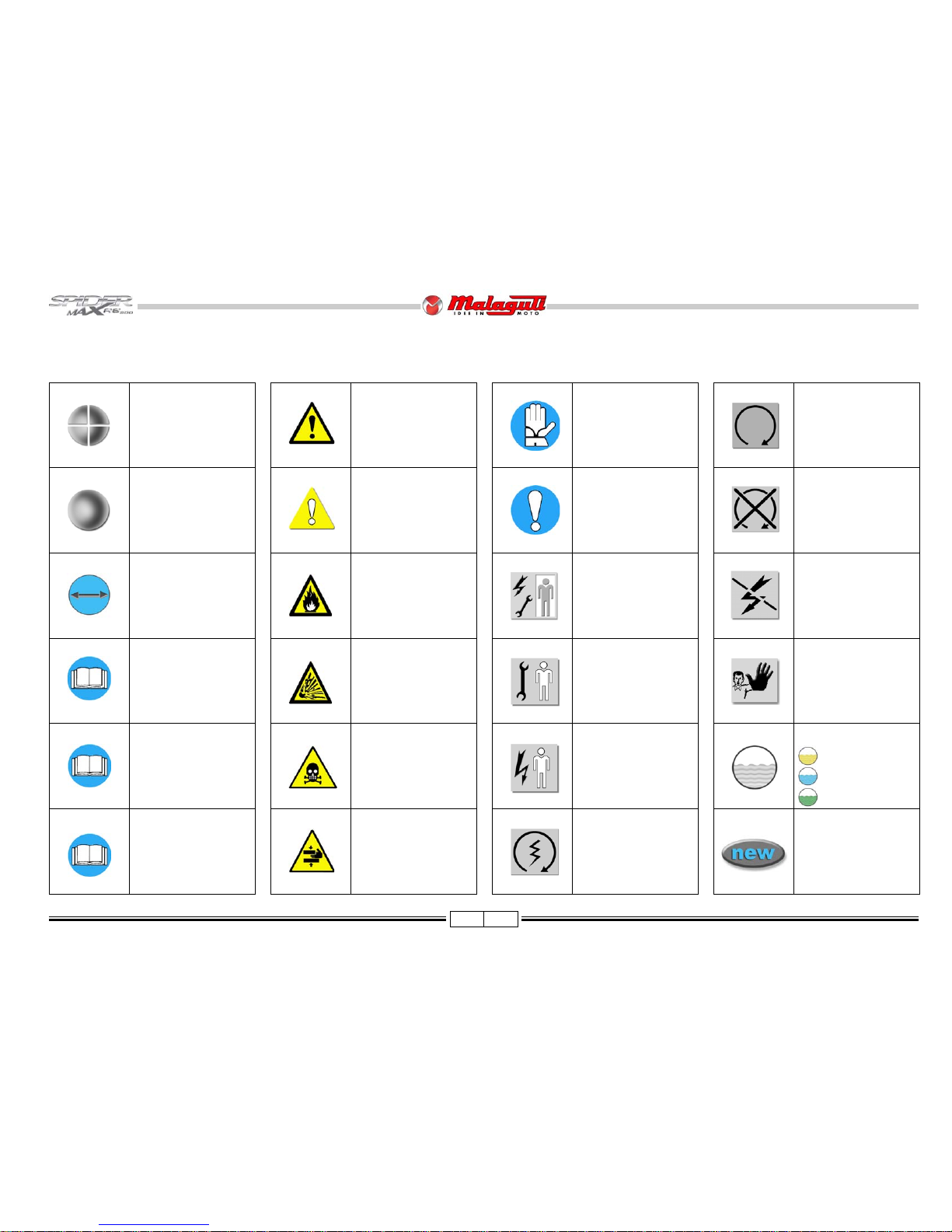
SYMBOL LIST
CAUTION!
Recommendations and
precautions regarding rider
safety and motor vehicle
integrity.
WARNING! Situations entailing
the risk of personal injury to
maintenance or repair
mechanics, other workshop
personnel or third parties, or
damage to environment,
vehicle or equipment
FIRE HAZARD.
Indicates operations which
may constitute a fire
hazard
RISK OF
EXPLOSION
Indicates operations
which may constitute a
risk of explosion
TOXIC FUMES
Indicates a possibility of
intoxication or inflammation
of the upper respiratory
tract
WARNING!
Danger of crashing
arms
SAFETY GLOVES
These operations require
the use of safety gloves
IMPORTANT
This topic requires special
attention
GENERAL SERVICE
PERSONNEL
Skilled electronic or
mechanical technician.
MECHANICAL
MAINTENANCE
Operations to be performed
only by an expert mechanic
ELECTRICAL
MAINTENANCE
Operations be performed
only by an expert electrical/
electronic technician
IGNITION KEY ON
(ON position)
PRESENT MANUAL
Information on the
present manual
“ENGINE” SERVICE
MANUAL
Indicates information which
may be obtained by
referring to said catalogue
SP ARE PARTS
CATALOGUE
Indicates information which
may be obtained by
referring to said catalogue
DISASSEMBL Y
OPERATIONS
ASSEMBL Y
OPERATIONS
SYMMETRICAL
OPERATIONS
Operations that must be
carried out also on the other
side of the unit or
component.
EMPTY THE CIRCUIT
REPLACE WITH NEW,
ORIGINAL SPARE
PARTS
IDLING ENGINE
Switch on the engine, at
idling speed, to perfom
these interventions.
ENGINE OFF
Indicates operations to
be performed with
engine off
POWER OFF
Indicates that negative
pole is to be disconnected
from the battery before
performing the operation
NO!
Operations to be
absolutely avoided
OIL
COOLANT
FUEL
Page 5
4 02/08
Before any servicing, make sure that the vehicle is perfectly stable.
The front wheel should preferably be anchored to fixture, which is integral with the lift platform.
GENERAL WORK PROCEDURES
• The recommendations given hereafter are aimed at ensuring maximum work safety as well as at considerably reducing the risk of accidents, personal injury, equipment
damage and idle times, and should therefore be strictly adhered to.
• Always listen with attention to the customer’ s opinion and complaints about the motor-bike operation, asking specific questions in order to ha ve a complete understanding of
all the symptoms and identify with good approximation the real causes of the trouble. The present man ual provides the technical information and the basic indications on the
intervention procedures but these have to be integrated with the personal e xpertise.
• We suggest planning the service interventions in order to avoid any waste of time or downtime. Try to reduce as much as possible the operations necessary to reach the
components that needs repairing.
• Prepare the components that are likely to be replaced and all the original spare parts you may need.
• Use only the original spare parts.
• Mark the components that may be mis-placed during re-assembly operations.
• Only use quality tools and equipment.
• Only use equipment conforming to EU Directives for lifting the vehicle.
• During operations, always keep tools and equipment at hand, possibly laying them out according to the sequence in which they are to be used. Absolutely avoid putting them on the
vehicle itself, out-of-sight or in poorly accessible places.
• Always keep the work area neat and clean.
• When tightening screws or nuts, start with the larger diameter or inner fasteners, and tighten them in progressive “pulls” using a “criss-cross” pattern.
• The torque settings specified in the manual refer to the “final torque”, which must be attained progressively by steps.
• Preferably use open-end box wrenches by “pulling” and not “pushing”.
Page 6
5 02/08
• Before carrying out any operation, wait f or all parts to cool down.
• For operations requiring two mechanics, make sure that the various steps to be performed by each of them are clearly defined and co-ordinated beforehand.
• Make sure that each component has been properly mounted before proceeding with assembling the next one.
• Always replace gaskets, O-rings, circlips and split pins at every refitting.
• Only use screwdrivers with sizes suitable to the screws to be loosened or tightened.
Never use open flames for any reason.
Never leave open containers or containers not suitable for holding fuel in passageways, close to heat sources, etc.
Never use petrol to clean the vehicle or the floor of the workshop. Always use low flash point solvents to clean the vehicle components.
When welding, make sure that there are no flammable liquids in the vicinity.
Never suck from or blow into the fuel pipe.
Never leave the engine running in closed or poorly ventilated areas.
Do not use fuses with a higher rated capacity than indicated: this may cause se v ere damages to the electrical system and burn a fire as a conse-quence of short circuit.
• Make sure that the vehicle is stable and not to have to take on awkward working positions.
• Never reuse old gaskets or circlips.
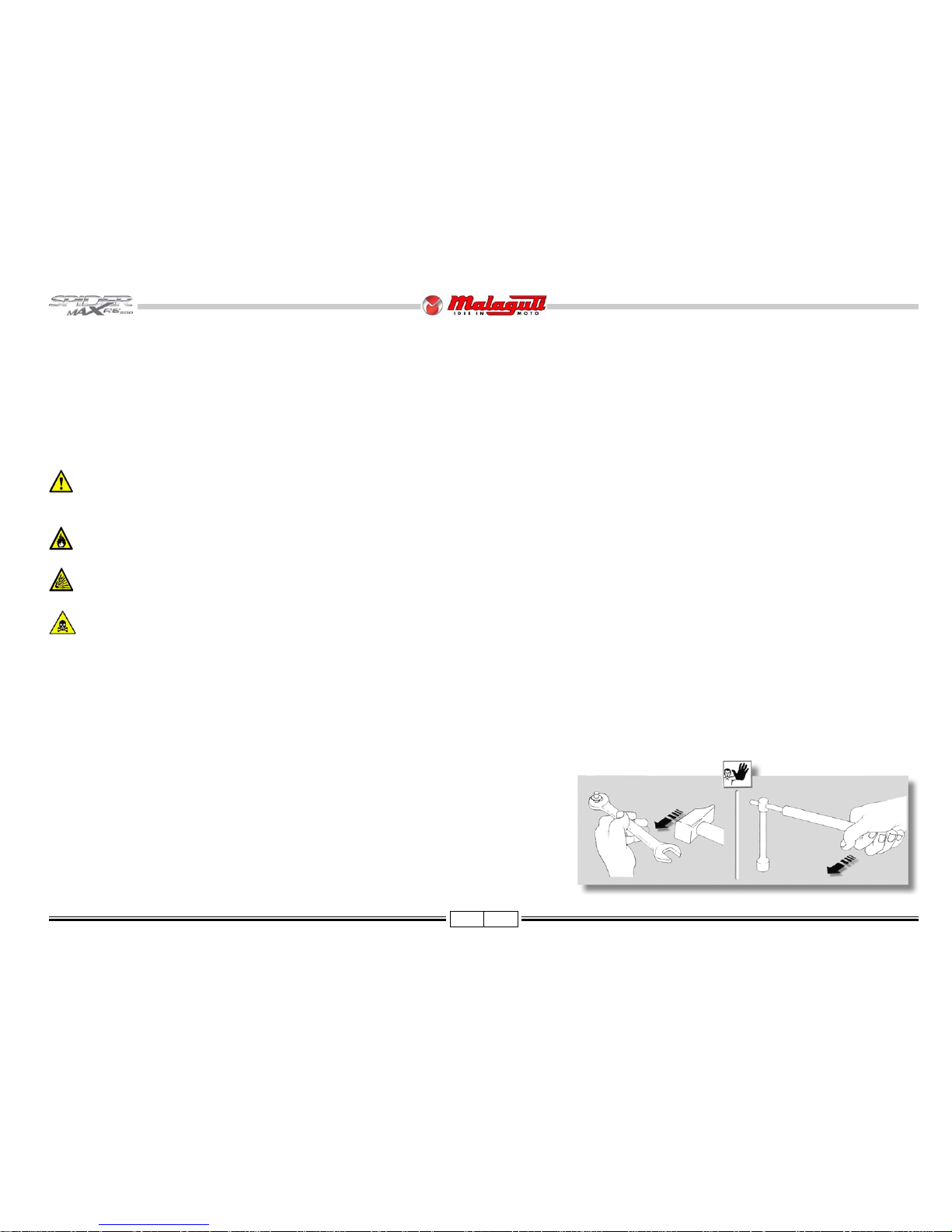
• Never use a screwdriver as a lever or chisel.
• Never use pincers to loosen or tighten screws or nuts because, in addition to not providing a sufficient clamping force, they may also damage the screw head or nut hexagon.
• Never tap the wrench with a hammer or other similar tool to loosen or tighten screws and nuts.
• Never attempt to increase the lever arm by fitting a tube into the wrench.
Page 7
6 02/08
CONTENTS
DESCRIPTION P.
RIGHT RADIA T OR - LEFT RADIA T OR 38
ELECTRICAL FAN RADIA TOR - EXP ANSION RESER VOIR - THERMAL EXP ANSION VAL VE 39
KEY SWITCH - DASHBO ARD P ANEL 40
LEG PROTECTOR 41
UPPER HANDLEBAR COVER - ACCESSES 43
FRONT AND REAR HANDLEBAR COVER - ACCESSES 44
HANDLEBAR - BRAKE MASTER CYLINDERS 45
DRIVER SEAT - ACCESSES 46
P ASSANGER SEA T - CUSHION DRIVER SEA T - GRAB HANDLE 47
HELMET COMP ARTMENT 48
ACCESSES - DIRECTION INDICA TORS AND T AIL LIGHTS 48
REAR FAIRING 49
TAIL LIGHTS 50
SIDE REACH - VOL T A GE RECTIFIER 51
COOLANT PUMP - COIL 51
RELA Y HOLDER 52
ACCESSES - ELECTRONIC INJECTION ECU THRO TTLE BODY 53
BA TTERY COMP AR TMENT - ACCESSES 54
FUEL TANK 55
AIRBOX 57
FRONT MUDGUARD - FRONT WHEEL - WHEEL SPINDLE 58
(FRONT BRAKE) DISCS - FRONT WHEEL - REASSEMBLY 59
BRAKE CALLIPERS - FRONT CALLIPER REPLACEMENT AND DISASSEMBL Y 60
LOWER F AIRING MUDGU ARD - FORK 63
ST ANCHION GROUP - STANCHION DISASSEMBL Y - CHECK THE OIL LEVEL IN THE ST ANCHION 63
FRONT FORK OIL REPLACEMENT 64
COMPLETE FORK 64
EXHAUST - EXHA UST MANIFOLD 65
LAMBDA SENSOR - REMOV AL - REASSEMBLING 66
REAR SHOCK ABSORBERS 67
REAR ARM - SHOCK ABSORBER SUPPORTING PLA TE 68
REAR CALLIPER - REAR CALLIPER DISASSEMBL Y 69
REAR WHEEL - (REAR BRAKE) DISC ENGINE 71
ENGINE REASSEMBL Y - ENGINE MOUNT 72
ANTI-VIBRATION CONNECTING RODS - ENGINE MOUNT 73
SUBFRAME 74
UPPER SUBFRAME - SIDE SUBFRAMES - CENTRAL ALUMINIUM FRAME 75
FRAME DIMENSION CHECK 76
CABLE POSITIONING, “PIPE SYSTEM” AND ANCHORING TIES 77
23
4
23
4
23
4
23
4
23
4
23
4
23
4
23
4
23
4
23
4
23
4
23
4
23
4
23
4
23
4
23
4
23
4
23
4
23
4
23
4
23
4
23
4
23
4
23
4
23
4
23
4
23
4
23
4
23
4
23
4
23
4
23
4
23
4
23
4
23
4
23
4
23
4
23
4
23
4
23
4
23
4
23
4
23
4
23
4
23
4
23
4
23
4
23
4
23
4
23
4
23
4
23
4
23
4
23
4
23
4
23
4
23
4
23
4
23
4
23
4
23
4
23
4
23
4
23
4
23
4
23
4
23
4
23
4
23
4
23
4
23
4
23
4
23
4
23
4
23
4
23
4
23
4
23
4
23
4
23
4
23
4
23
4
23
4
23
4
23
4
23
4
23
4
23
4
23
4
23
4
23
4
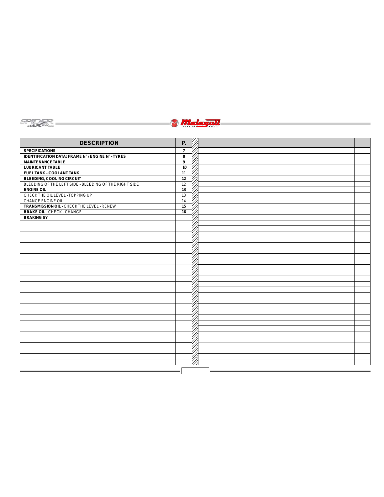
DESCRIPTION P.
SPECIFICATIONS 7
IDENTIFICATION D A T A: FRAME N° / ENGINE N° - TYRES 8
MAINTENANCE TABLE 9
LUBRICANT TABLE 10
FUEL TANK - COOLANT T ANK 11
BLEEDING, COOLING CIRCUIT 12
BLEEDING OF THE LEFT SIDE - BLEEDING OF THE RIGHT SIDE 12
ENGINE OIL 13
CHECK THE OIL LEVEL - TOPPING UP 13
CHANGE ENGINE OIL 14
TRANSMISSION OIL - CHECK THE LEVEL - RENEW 15
BRAKE OIL - CHECK - CHANGE 16
BRAKING SYSTEM BLEEDING - INTEGRAL SYSTEM 17
CHECK THE LEVEL OF THE BRAKE LIQUID - FR ONT LEFT CALLIPER 17
CHECKING BRAKE PADS AND DISCS - BRAKE P ADS 18
REPLACING THE BRAKE P ADS - DISCS 18
FORK - CHECK THE OIL LEVEL IN THE ST ANCHION 19
FRONT FORK OIL REPLACEMENT 19
REAR SHOCK ABSORBER ADJUSTMENT - STEERING 2 0
HANDLEBAR ADJUSTMENT 2 0
LOCATION OF THE MAIN ELECTRICAL ELEMENTS 21
INSTRUMENT BOARD 23
KEY SWITCH - HANDLEBAR LOCK 24
LOCKING - DISENGAGING 24
STAR TING THE ENGINE 24
LIGHTING SYSTEM - LAMPS 25
ADJUSTING THE BEAM LIGHT 26
FUSES - GENERAL PROTECTION FUSE AND CHARGE PROTECTION FUSE 27
BA TTERY ASSEMBLY - CHARGE BA TTERY 28
SP ARK PLUG - REMPLACE 29
PROCEDURES FOR DISMANTLING AND REMOVING COMPONENTS 30
REASSEMBL Y NOTE - CENTRAL F AIRING - REAR VIEW MIRRORS 30
FRONT DIRECTION INDICA TORS (BULB CHANGE) 30
ACCESSES - REPLACING THE FRONT PARKING LIGHT 31
DASHBOARD - BRAKING DISTRIB UTOR - HORN 32
AIR GRID - WINDSCREEN - FRONT F AIRING 33
ACCESSES - IMMOBILIZER ECU 35
SIDE STAND SWITCH - FUEL SUPPLY PUMP 36
RADIATORS 37
Page 8
7 02/08
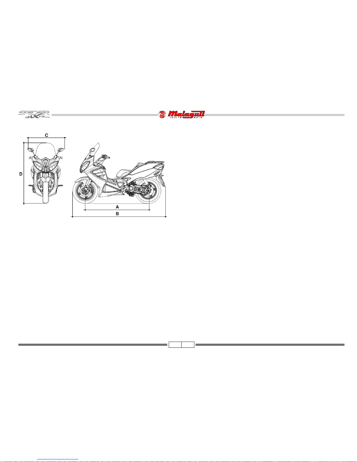
DIMENSIONS
Wheel base (A) m .......................................................................................1,490
Max. length (B) m........................................................................................2,200
Max. width (C) m.........................................................................................0,930
Max. height (D) m........................................................................................1,470
Kerb weight kg ...............................................................................................230
Max. load with rider , passenger and luggage kg..............................................180
CAP ACITY
Engine oil cm3 ........................................................................................... 1700*
T ransmission oil cm3 ................................................................................... 250*
Fuel tank (total).............................................................................................. 14 *
ENGINE: single-cylinder , f our-valve
Valves type............................................................................. PIAGGIO M34CM
n° Cylinders ...................................................................................................... 1
Bore x stroke mm .................................................................................. Ø 94x71
Capacity cm3.................................................................................................493
Compression ratio ............................................................................... 10.5 ± 0.5
Cooling........................................................................................................ liquid
Starting system ............................................................................electric starter
Greasing system.................................................................................. wet sump
SP ARK PLUGS
Type.............................................................................................. NGK CR7EKB
TRANSMISSION
Automatic speed variator with expandab le pulleys, V-belt, automatic
dry centrifuge clutch, reduction gear and transmission
compartment with forced circulation cooling system.
FUEL SYSTEM
Electronic injection with electrical fuel pump.
Fuel: unleaded petrol.
ELECTRONIC IGNITION
High efficiency , inductive type coupled with the injection system,
variable advance and separate HV coil.
BRAKES
The braking system is hydraulically operated and features double front disc (2
discs with a diam. of 270 mm) and rear disc (260 mm diam. disc) with braking
distribution system. The brak es are operated as follows:
Left lever: rear lever + front lever (right hand side of the vehicle)
Right lever: front brake (left hand side of the vehicle)
CHASSIS
“V-Bo x” type, composed of a double pressure die cast shell made of aluminium,
coupled, on the front and rear sides, to a steel pipe frame.
SUSPENSIONS
Fr o n t: hydraulically controlled fork with two Ø 41 mm rods.
Stroke: 120 mm
Rear: 2 hydraulic shock absorbers with adjustable preloading spring.
BA TTER Y
12V , 14Ah, maintenance-free.
TIRES
Fr on t: 120/80 - 16 60 S
Rear: 150/70 - 16 68 S
*
Indicative V alue
SPECIFICATIONS
F. 1
Page 9
8 02/08
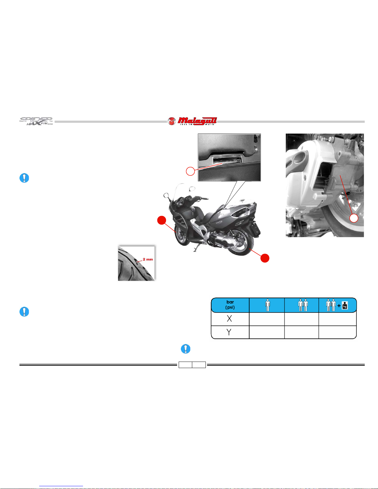
TYRES
Type: T ubeless (without inner tube)
It is possible to use tyres with load and speed indexes that are higher
than or identical to those indicated.
It is however necessary for speed indexes to be identical for both
tyres. Use only tyres with the relevant type approval.
Tyre inflation pressure must be adjusted while the tyre is at ambient
temperature.
150/70 - 16” - 68S
120/80 - 16” - 60S
2.3 2.3 2.3
(33.4) (33.4) (33.4)
2.3 2.3 2.3
(33.4) (33.4) (33.4)
B
F. 2
F. 3
A
• To read the vehicle’s identification number (VIN) (A) lift the saddle
and remove the cover located in front of the helmet compartment.
• Engine identification data are located on the left-hand engine crankcase (B).
Any alteration to the vehicle identification data is pursued
by the Law.
Minimum tread depth is 2 mm.
• There are T.W.I. marks all around the tyre
sides. These correspond to tyre wear
indicators situated in the tyre’s tread; if
there is no difference between the
thickness of the tyre wear indicators and
the tread depth, the tyre must be replaced.
F. 4
X
Y
IDENTIFICATION DATA: FRAME N° / ENGINE N°
Page 10
9 02/08
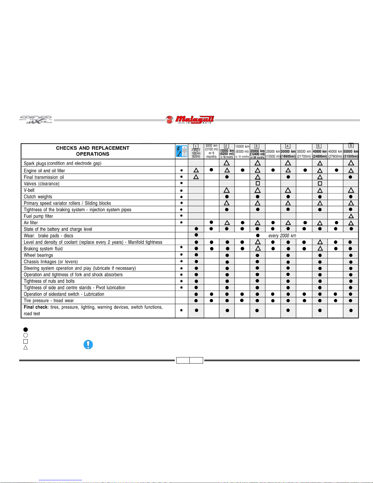
MAINTENANCE TABLE
NOTE - Maintenance operations should be performed more frequently if the vehicle is used in rainy weather, in dusty places or on rough
terrain.
Due to their simplicity, checks with no asterisk CAN also be carried out b y technicians not authorised by MALA GUTI, b ut under
their direct responsibility.
Nr. : coupon
: check
: clean
: adjust
: replace
Page 11
10 02/08
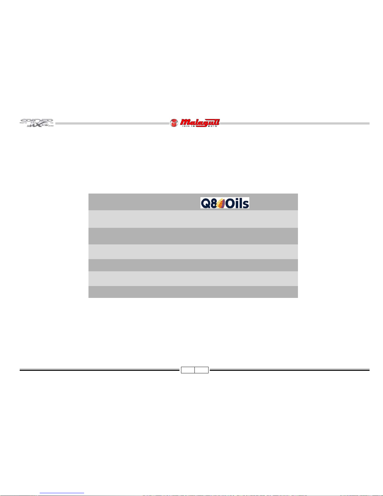
LUBRICANT TABLE
NOTE - Use only recommended products.
LUBRICANTS
ENGINE OIL (4-STROKE TYPE) FORMULA EXCEL SAE 5W40
ENGINE TRANSMISSION OIL ZC 90
AIR FILTER LUBRICANT AIR FILTER OIL
RADIATOR FLUID Q8 LONG-LIFE RED
BRAKE CIRCUIT FLUID BRAKE FLUID DOT 4
FORK ROD OIL FORK OIL
Page 12
11 02/08
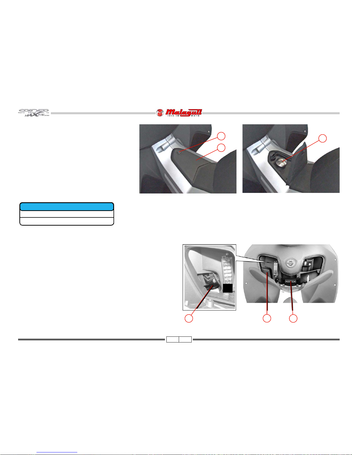
FUEL TANK
To access the fuel tank, proceed as follows:
• Place the vehicle on the centre stand.
• Remove the ignition key from the ignition block.
• Open the door (A) in front of the seat, by acting on the lever
(B).
• Insert the ignition key, remove the cap (B) and refuel the
tank.
• After refuelling, immediately remove any possible traces
of fuel from the vehicle body, since fuel may deteriorate
the vehicle’s outer surfaces.
Use UNLEADED PETROL.
F. 5
F. 7
COOLANT TANK
• T o access the engine coolant tank, open the glov e compartment (A) located at the
centre of the lower fairing and remove the plastic co ver (B). Owing to the particular
position of the tank, the level of coolant, with respect to the minimum and maximum
level marks, can be checked through the grid under the upper fairing, on the front
side of the vehicle. Use the coolant prescribed in this manual - or one having
identical characteristics - for any topping up. Never unscrew the tank cap (T) when
the engine is warm, so as to avoid burnings. Do not top up with water, except in
emergency situations and in this case, have the entire contents of the tank replaced
by a suitable product as soon as possible.
A
*
Indicative V alue
B
T
14*
3*
F. 6
A
B
C
FUEL TANK Litres
TOTAL TANK CAPACITY
RESERVE
Page 13
12 02/08
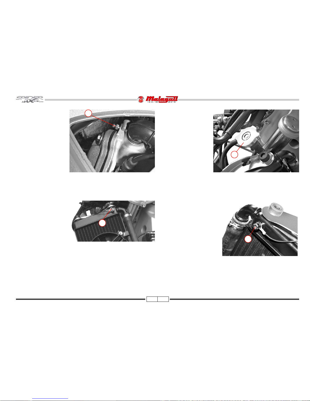
BLEEDING, COOLING
CIRCUIT
T o bleed the air , with the
circuit completely drained
from the coolant, proceed as
follows:
BLEEDING OF THE LEFT
SIDE
• Remove the cap on the
bleeding coupling (A).
• Fit a tube in the coupling
(A) of the bleed nipple on
the cylinder head.
• Refill the expansion reser-
voir with coolant, as described: (P. 11).
• Release and remove the
filler (B).
• Pour some coolant in the
main radiator (left).
• Slacken the coupling (A)
and go on refilling the main
radiator until some liquid
would drip off the tube (with
regular flow).
• Now, close the b leed nipple
(coupling - A) and fill in up
to the rim of the main
radiator.
• Slacken the bleed screw (C),
until some liquid drips off with
regular flow.
• Close the screw and top up
the liquid.
• Open the bleed nipple on the
cylinder head and check the
tubes for liquid dripping,
showing that the bleeding
has been correctly carried
out.
• Close the coupling (A) back.
F . 7/a
F . 7/c
BLEEDING OF THE RIGHT
SIDE
• Slacken the bleed screw (D),
until some liquid drips off with
regular flow.
• Close the screw and top up the
liquid in the main radiator.
• With the help of an assistant,
slightly tilt the vehicle on the right side and, keeping it in this
position, slightly slacken the
screw (D), to let any remaining
air out of the right radiator.
• Tighten the bleed screw (D),
F . 90/a
which act as the ground screw .
• Open the bleed nipple on the cylinder head and check the tubes for liquid dripping,
showing that the bleeding has been correctly carried out.
• Close the coupling (A), remove the tube and fit the cap.
• Check the main radiator is completely refilled with coolant; top up and refit the filler
(B), if necessary.
F . 7/d
F . 7/b
C
A
B
D
Page 14
13 02/08
ENGINE OIL
• As far as four-stroke engines are concerned, engine oil is used to lubricate distribution components, base bearings
and thermal unit. An insufficient amount of oil can seriously damage the engine.
• In all four-stroke engines, deterioration of the oil and a certain consumption are to be considered normal.
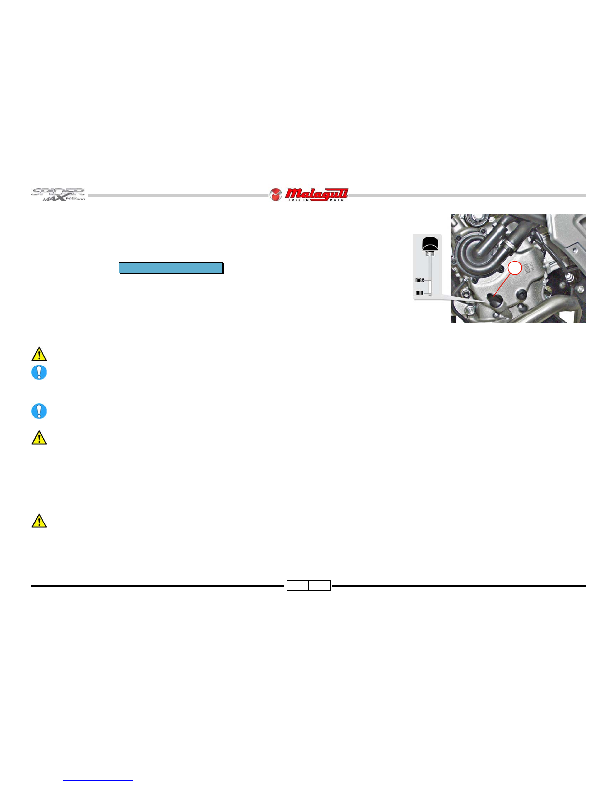
CHECK THE OIL LEVEL
This check should be performed when the engine is cold, as described below:
1) Park the vehicle on flat ground and put it on its centre stand (e v en a slight inclination ma y alter results).
2) Unscrew the cap/dipstick (A), dry it with a clean cloth and refit it, wrenching it firmly in place.
3) Remove the cap/dipstick and make sure the le vel falls betwe en the MAX and MIN notches; if necessary, top up
with Q8 FORMULA EXCEL SAE 5W40 oil.
The MAX level notch corresponds to quantity of about 1700 cm3 of oil in the engine.
If you need to check the level when the engine is warm, remember that the level line will be lo wer . It is best to wait at least 10 minutes fr om stopping the
engine in order to have a correct reading.
The vehicle features a control system that activates the “LO W OIL PRESSURE” alarm signal of the digital instrument boar d in the event of trouble.
TOPPING UP
Before topping up, check the oil level and in no case allow the level to rise above the MAX notch.
• T opping up to le v el falling betw een the MIN and MAX marks means using about 400 cm3 of oil.
Never allow the level to rise above the MAX mark! This may seriously damage the engine, due to excessive internal pressure.
• Every 3000 km, it is recommended to have the engine oil checked.
ALARM MESSAGE (LO W OIL PRESSURE)
The digital instrument board features a control system displaying a “LOW OIL PRESSURE” message (B - § 3.11.6). The message appears when the vehicle is turned on to
signal that the check function is working. The message disappears automatically after a f e w seconds . It will only reappear during vehicle use if there is actually a low oil
pressure problem.
If the message appears when you are braking, when the engine is idling or when curving, stop the vehicle, check the oil le vel and top up if necessary .
Every 3,000 km, the message OIL is displayed on the digital instrument board. This warning light indicates that it is time to change the engine oil. This
warning light is displayed on the instrument board until the indicated operation is carried out.
Waste oil is toxic f or the environment, therefore we suggest you contact an A uthorised Service Centre for disposal according to the rules in for ce.
every 3000 km or 6 months
F. 8
A
Page 15
14 02/08
every 6000 km or 12 months
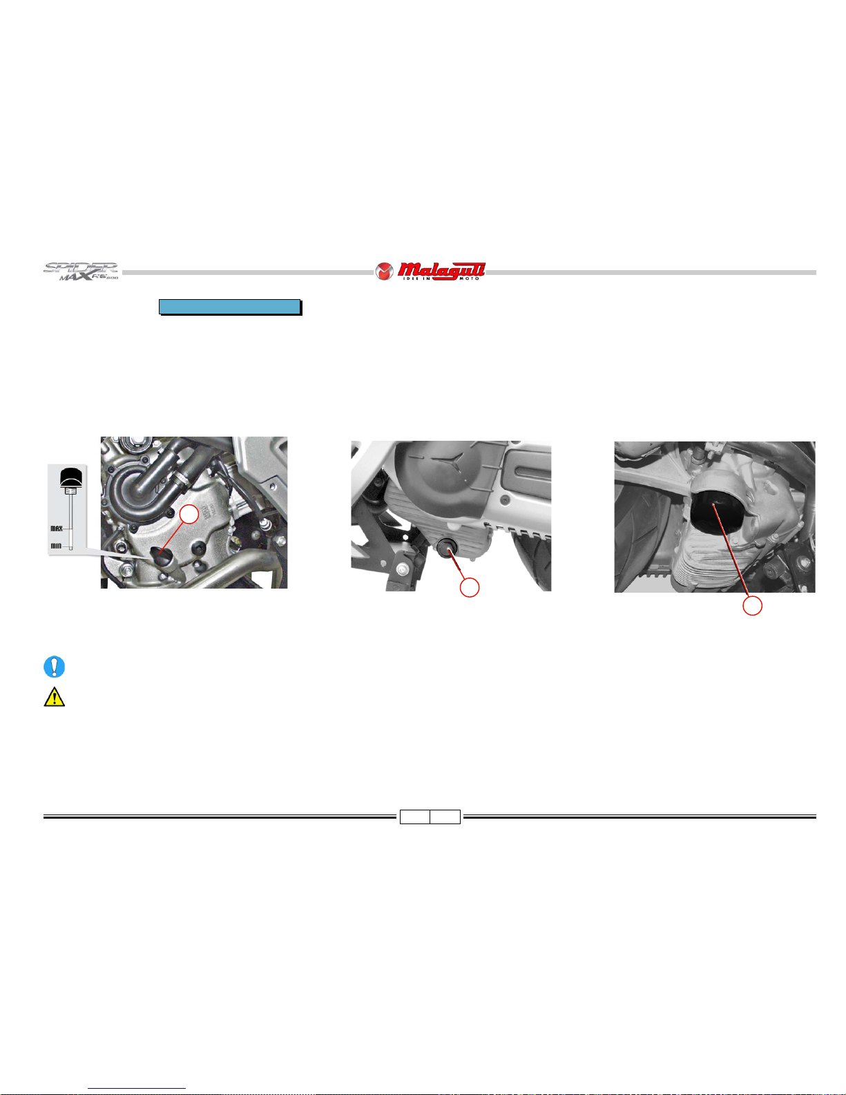
CHANGE ENGINE OIL
• The engine must be emptied by letting the oil flow from the drainage cap (B) of the filter beside the transmission. To facilitate drainage, loosen the cap/dipstick (A F. 8/a).
• Unscrew the cartridge filter (C) and remove it. Fit a ne w filter , and lubricate the O-rings with engine oil. Since a certain amount of oil remains in the circuit, fill through the cap
(A) using about 1500 cm3 of oil. Start the vehicle, let it run for a few minutes and turn it off: after 5 minutes, check the level and top up b ut never above the MAX mark.
F. 9
B
F . 9/a
C
The cartridge filter must be replaced every time the oil is changed. For topping up and replacement use Q8 FORMULA EXCEL SAE 5W40 oil.
Letting the engine run with an insufficient amount of lubricant or with the wrong types of lubricant causes wear to moving parts and can in the long run
cause serious damage.
Waste oil contains polluting substances. Ha ve oil replaced by an Authorised Service Centre that will also dispose of waste oil in accordance to the la w.
F . 8/a
A
Page 16
15 02/08
Max
Min
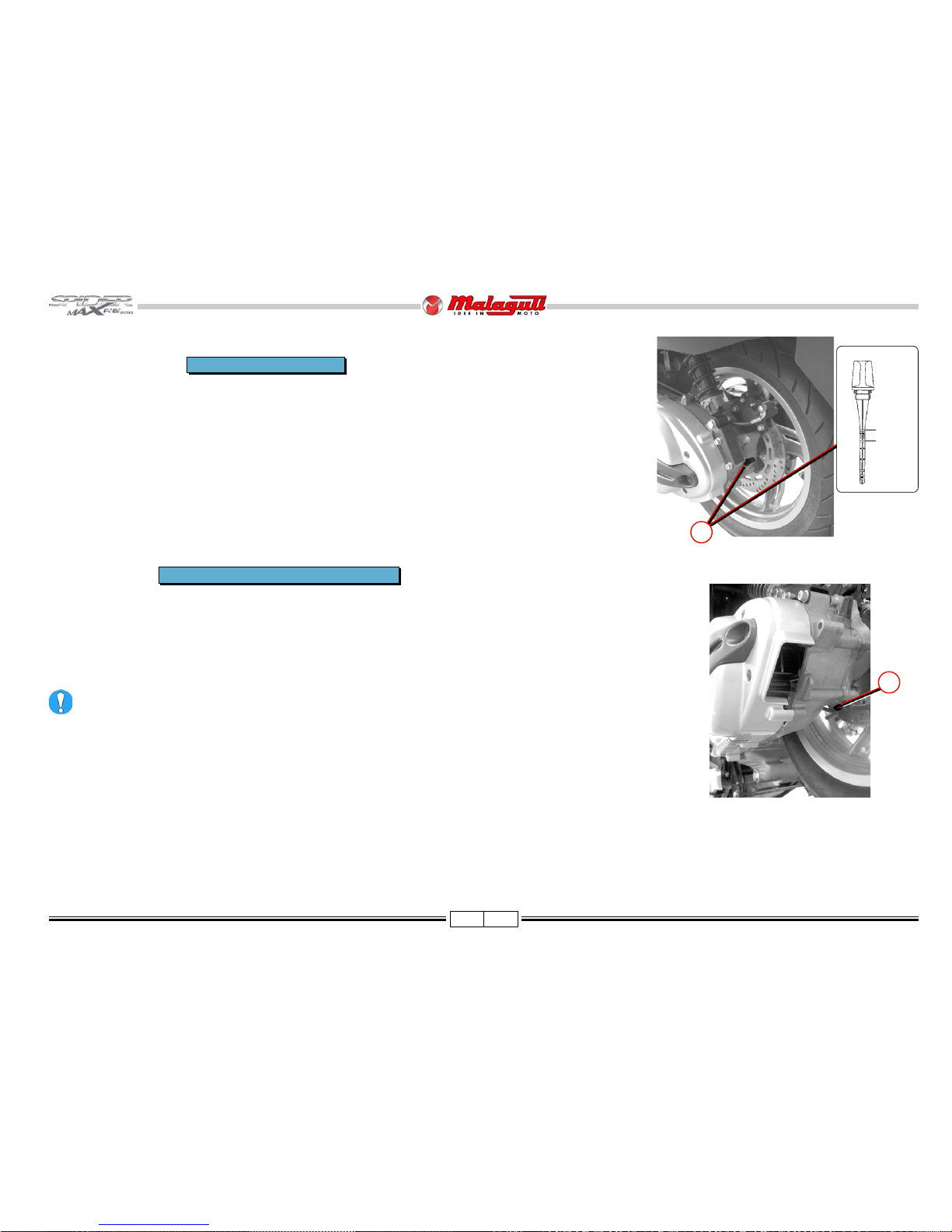
TRANSMISSION OIL
CHECK THE LEVEL
1) Place the vehicle on a level surface on its centre stand.
2) Unscrew the dipstick (A), clean it and refit it, wrenching it tightly.
3) Pull it out again and check that the oil level is between the MIN and MAX notches.
4) If the level is insufficient, top up until you almost reach the MAX notch.
5) Fill the crankcase with this type of oil: Q8 ZC 90
Crankcase capacity approx.: 250 cm3
RENEW
• Carry out the operations described above at points 1-2, without refitting the dipstick; then put a container under the
engine crankcase and unscrew the drainage screw (B), paying attention to the gasket.
• Let oil flow into the container (pay attention to avoid scorching).
• Refit the drain plug with gasket and fill with approximately 250 cm3 of new oil (Q8 ZC 90), then refit the cap and
dipstick (A).
• Now repeat checks 3-4-5. If the drainage screw gasket is damaged, replace it.
Regularly check for oil leakages near the drain plug at the rear wheel.
every 6000 km or 12 months
after the first 1,000 km and every 24,000 km
F. 1 0
F. 1 1
A
B
Page 17
16 02/08
MIN
S
CHANGE
If the fluid features traces of dirt, debris or water, it m ust be replaced. A soft and spongy feeling in the brake le ver can indicate the presence of air in the
circuit.
CHECK
• The visual check should be made through the sight glass (S) of the tanks: front
brake (A) and rear brake (B), when the vehicle is on level ground and perfectly
upright.
• The oil should be at 3 mm from the bottom edge of the sight glass.
BRAKE OIL
When topping up, never use more than one oil.
F. 1 2
every 30 days
every 12.000 Km or 24 months
A
B
MIN
S
F. 1 3
Page 18
17 02/08
BRAKING SYSTEM BLEEDING
INTEGRAL SYSTEM
Put the vehicle on firm and level ground.
• Remove the cover of the oil pump tank (left-hand side), releasing the two screws, so as to top up the liquid.
NOTE - The left brake lever allows the front right brake calliper and the rear brake calliper to be controlled interlockedly
at the same time.
To b leed the circuit of the integral system, fir st bleed the rear brake calliper .
• Fill in the left brake liquid tank up to the maximum level.
• Remove the rubber cap (A) from the bleed screw (B) and fit the rubber hose to collect the brake liquid.
• Operating the left brake lever , charge and pressurise.
• Keeping the left brake le ver oper ating, slack en the bleed scre w to let the air out. Then, tighten the bleed screw (B).
• Repeat the operation until only brake liquid is let out of rubber hose.
• These operations should be repeated for the front right calliper.
• Restore the level of the brake liquid in the sump.
During the bleeding, av oid the contact between the brake liquid and the bodywork, to avoid dama ges. Moreover , during the bleeding of the brake callipers,
avoid the contact between the liquid and the brake discs or the brake pads. Failure to observe this rule may affect the functions and the efficiency of the
braking system. If, during the bleeding, more air would come out, check all of the couplings: if they do not show any malfunctioning, look for the entrance
of the air in the different seals of the pump and in the pistons of the calliper.
During this operation, oil may leak from the bleed screw on the calliper and on the disc: if so, carefully dry the calliper and degrease the disc.
CHECK THE LEVEL OF THE BRAKE LIQUID (P. 16)
FRONT LEFT CALLIPER
• T o bleed the front left calliper, operate the right brake lever.
F. 1 4
B
A
B
12 ÷ 16
Page 19
18 02/08
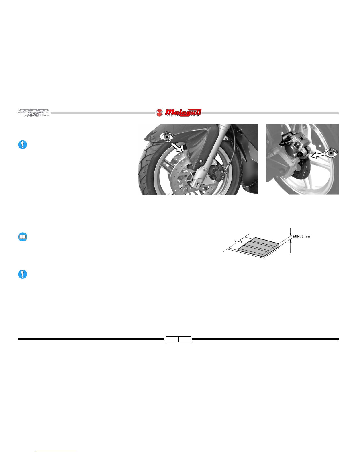
CHECKING BRAKE PADS AND DISCS
BRAKE P ADS
Check front and rear brake pads and discs for wear
every 2,000 Km.
• Visually check the thickness of the brake pads as shown
in the picture.
The minimum thickness of the brake pad lining should
not be thinner than 2 mm.
• Replace the brake pads in case their thickness is below
the allowed limit or they are damaged.
REPLACING THE BRAKE PADS
F. 17
F. 1 5
F. 16
DISCS
Check the discs for wear and replace if necessary (service limit 4.5 mm).
In case of abnormal wear or signs of scoring, carry out grinding.
For instructions on how replacing the front and rear brake pads please refer
to pages 60 and 61.
Page 20
19 02/08
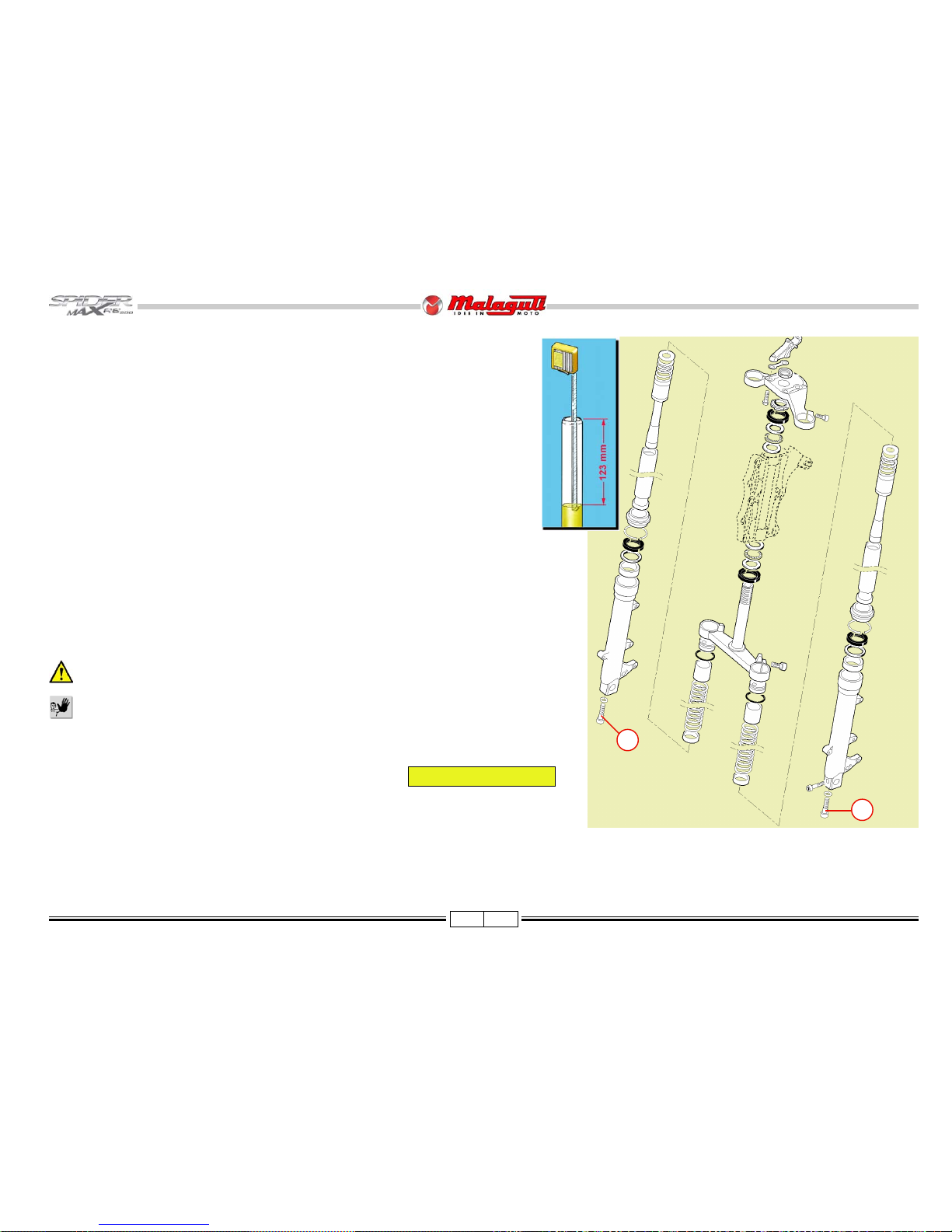
FORK
CHECK THE OIL LEVEL IN THE STANCHION
• In there case if the “limit switch” of the front fork or irregular noise, check the oil
level inside the fork stems by removing the stems, as shown in the picture, and
follow the instructions at page 63.
• Bring to the limit (downwards) the leg, keeping it in perfect vertical position.
• Using a meter or the stick of a gauge, check the proper oil level, which should be at
mm 123 from the upper edge of the leg.
• If necessary, top up with oil: Q8 FORK OIL
F. 1 8
V
V
FRONT FORK OIL REPLACEMENT
• Place a suitable container under the stanchion and remove the screw (V).
• Allow as much oil as possible to drain out.
• Disassemble the stanchions, as previously described.
• T urn ov er the stanchion, to let the remaining oil drain out.
The hydraulic oil is corrosive and may cause personal damages.
Do not dispose of spent oil in the environment.
• Refit the drain screw (V).
• Carefully pour the new oil in the leg.Carefully pour the new oil in the leg.
• Check the oil level, as previously described.
• Refit the components of the legs and the legs themselves on the motorcycle.
Quantity per leg 385 cc.
Page 21
20 02/08
REAR SHOCK ABSORBER ADJUSTMENT
• The rear shock absorbers can be adjusted on the spring pre-load allowing to adapt the motorcycle behaviour
according to the load, the type of ride and the road.
• Use the supplied wrench on the ring nut placed in the shock absorber lower part; rotating it counterc lockwise to
increase the spring power.
• In case of an exceeding friction, use force tube and the shock absorber wrench.
Four adjustments are possible:
1) Driver only
2) Driver and luggage compartment
3) Driver and passenger
4) Driver, passenger and luggage compartment
F. 1 9
F. 2 0
STEERING
PLA Y CHECK
• Place the motorcycle on the central stand.
• Rotate the handlebar repeatedly in both directions, to check that the ball bearings can slide smoothly .
• In case of (a light) friction during rotation or exceeding smooth sliding, adjust it by means of the appropriate wrench.
HANDLEBAR ADJUSTMENT
T o adjust the handlebar , proceed as follows:
• Remove the handlebar upper cover .
• Slacken moderately the screws (V4).
• Adjust the handlebar position, lifting or lowering it with both hands.
• After finding the right adjustment tighten the screws (V4), in a criss-cross pattern, until reaching the specified
torque.
V4
30 ± 20%
V4
Page 22
21 02/08
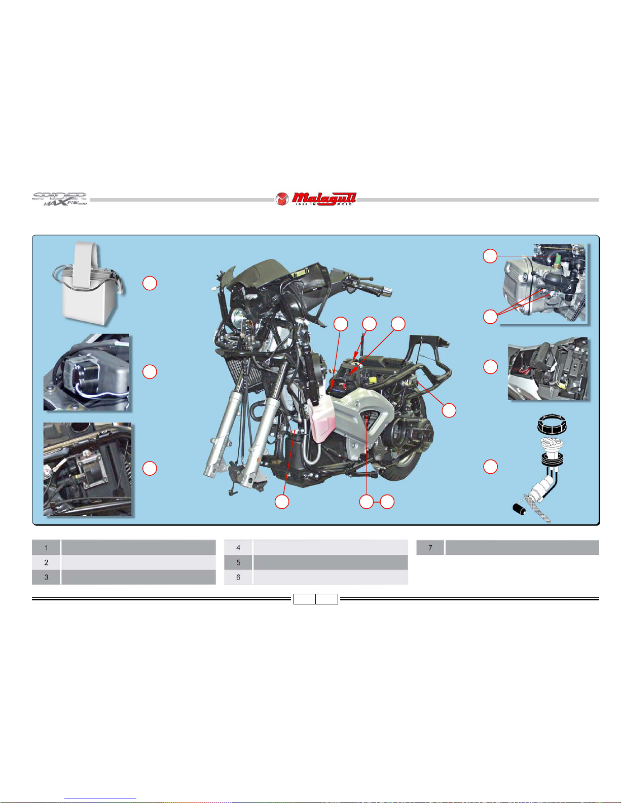
LOCATION OF THE MAIN ELECTRICAL ELEMENTS
F. 21
Battery
Rollover sensor
Ignition coil
Spark plugs
Temperature sensor
Relays and flasher
Fuel pump
1
3
1
2
3
6
7
26
7 4 5
5
4
Page 23
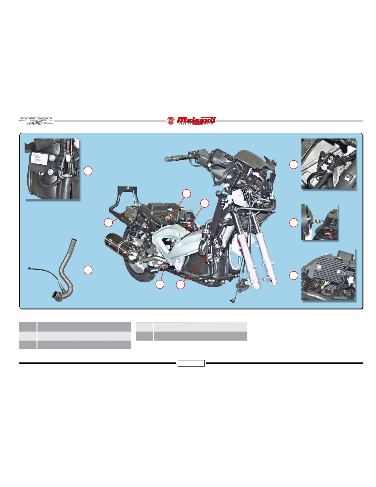
22 02/08
F. 22
8 Immobilizer control unit
9 Lambda sensor
10 Fuel injector
11 Regulator
8
9
10
11
11
8
10
9
12 Diagnostic plug
12
12
Page 24
23 02/08
F. 2 3
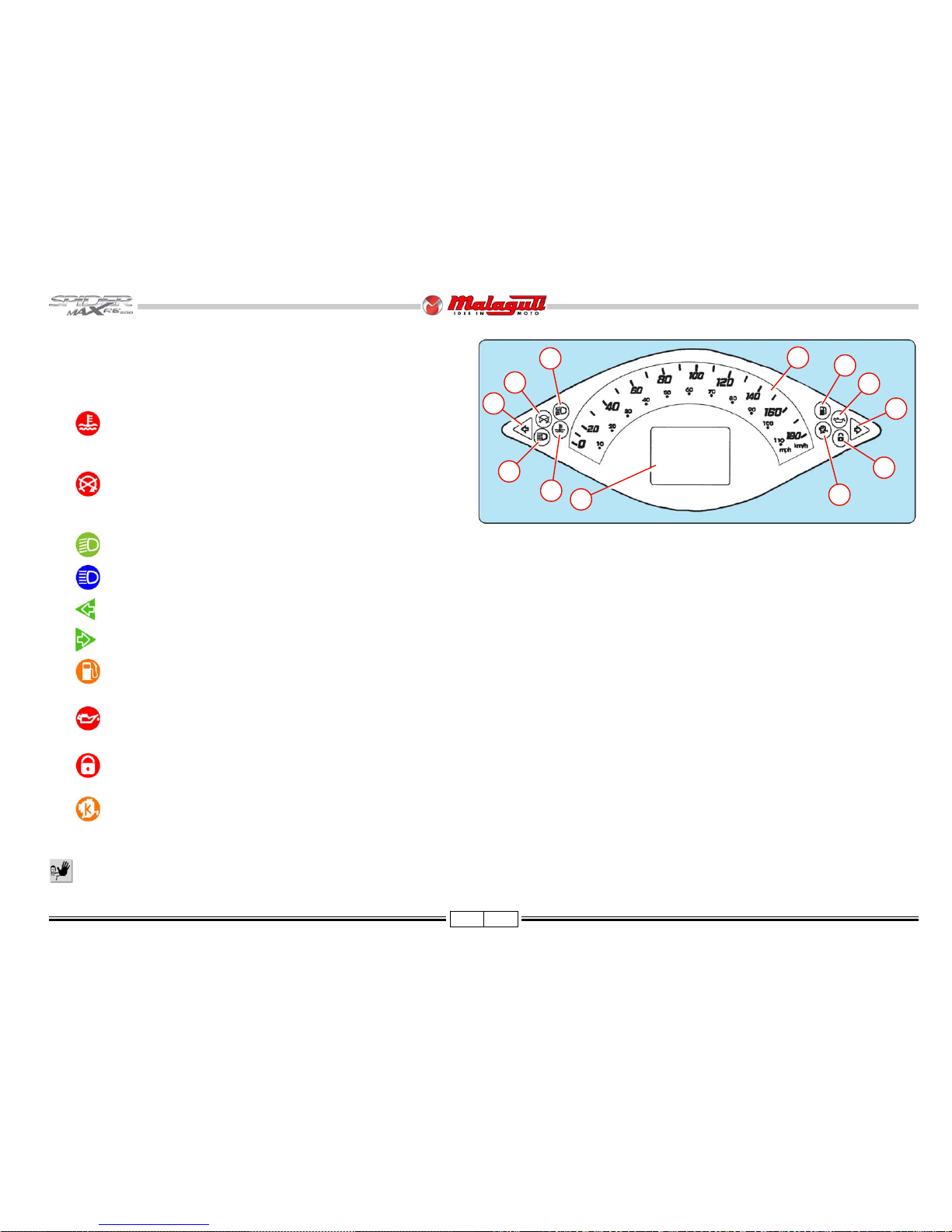
INSTRUMENT BOARD
1) Multifunction digital instrument board
2) Analogue instruments, Speedometer
This indicates the current speed in km/h or mph.
3) Coolant temperature
The warning light comes on to indicate that the coolant temperature is
too high.
4) Sidestand / engine stop
This light comes on to indicate that the sidestand is down and that the
“Engine Stop” button is OFF.
5) Low beam
6) High beam
7) Left hand turn
8) Right hand turn
9) Fuel level
The warning light comes on to indicate that the reserve amount has been reached.
10) Oil
This light comes on while the engine is running to indicate that engine oil pressure is insufficient.
11) Immobilizer
After about 20 days, the light stops flashing in order not to discharge the battery. However the immobiliz er function is still active.
12) Injection
This light comes on while the engine is running to indicate that the injection system is not functioning correctly; contact an Authorised MALAGUTI Service Centre.
Avoid cleaning the instruments with pressurised c leaning systems in order to prevent any dama ge.
9
10
11
12
5
6
7
8
1
2
3
4
Page 25
24 02/08
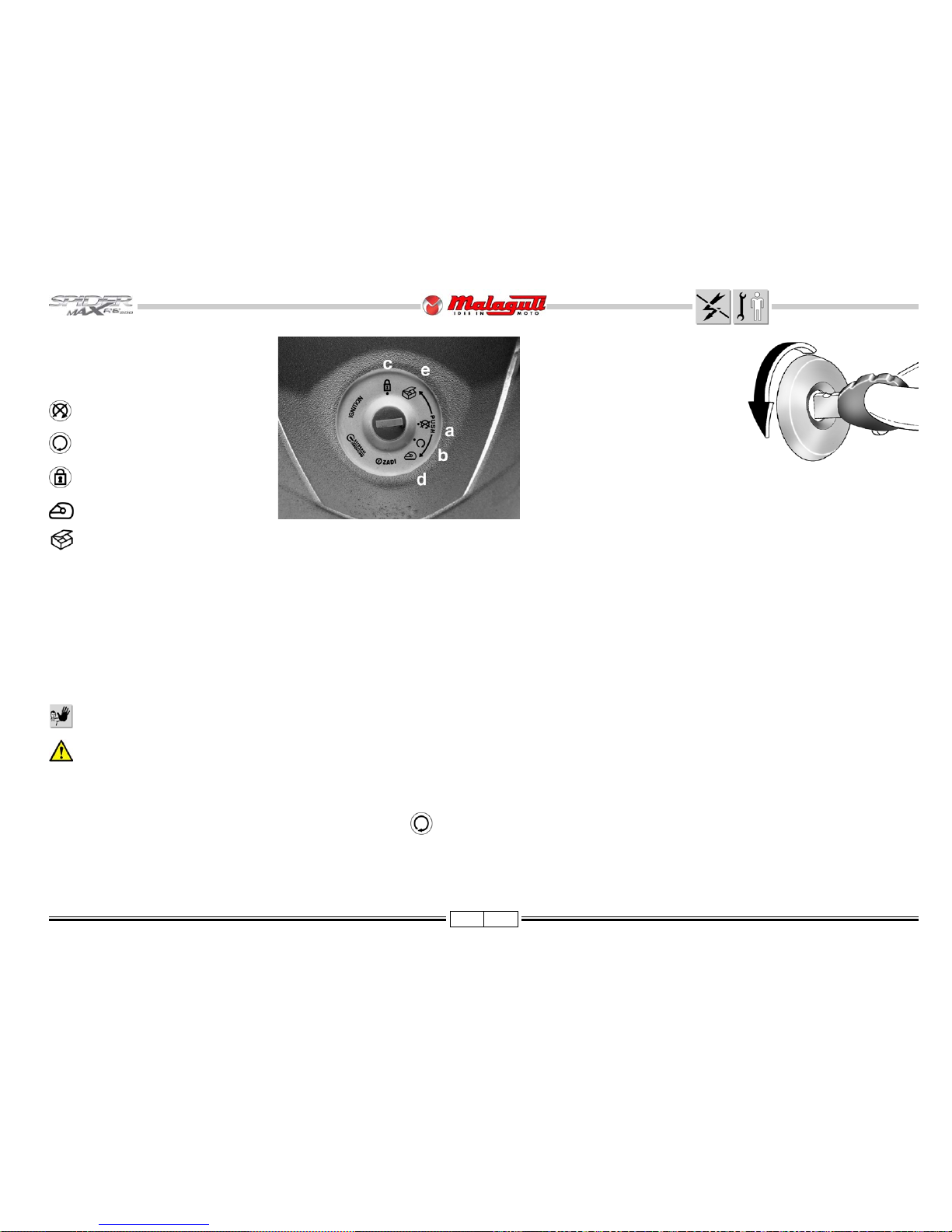
KEY SWITCH
• This switch controls the ignition circuit and
the handlebar lock.
Ignition disabled (the key can be
removed).
Ready to start’ position (the key
cannot be emoved).
Handlebar lock activated (ignition is
disabled. The ke y can be remov ed)
Helmet compartment opening position
Glove compartment opening position
HANDLEBAR LOCK
LOCKING
Turn the handlebar all the way to
the right or left, push the key in
and turn it counter-clockwise (F. 8).
DISENGAGING
Turn the key clockwise.
NOTE - The motor-bike is not
equipped with kick starter.
F. 24
F. 25
NOTE - The vehicle is supplied with two keys. If you lose both ke ys, you will have to replace the entire key block and ‘Immobilizer’ system.
ST AR TING THE ENGINE
• The engine cannot be started if the sidestand is down or if the emergency stop button is turned OFF.
• Before pressing the ignition button, pull the front or rear brake le ver and keep it pulled to start the engine, since this lever acts on a special ignition consent switch.
If the tank is empty, do not operate the «START» button and do not turn the key «ON» as this would damage the injection system.
If the engine does not turn on, release the ignition switch, wait a few seconds, then try again. Do not operate the ignition system for more than 10 seconds
at each attempt.
CHECKING THE WARNING LIGHT OF THE ENGINE OIL PRESSURE SENSOR (AUT OMA TIC)
• When turning the ignition key inserted in the ignition block to position ( ), without starting the vehicle, the displa y should show the message LOW OIL PRESSURE f or
about 8 seconds, to signal that the engine oil pressure sensor is working; the LOW OIL PRESSURE message must disappear when the vehicle sets off. Should the message
not appear on the display, check the engine oil level before starting the vehicle.
Page 26

25 02/08
C
B
A
B
C
D
E
G
F
G
F
E
F. 2 6
LIGHTING SYSTEM
LAMPS
Functions Specifications Replacing (page)
A (F ront) parking light 12V - 5W (W5W) 31
B Low beams/high beams 12V - 35/35W (HS1) 35
C Front direction indicators 12V - 21W (PY21) 30
D Number plate light 12V - 5W (W5W) -
E Rear direction indicators 12V - 16W (W16W) 48
F (Rear) parking lights 12V - 5W (R5W) 50
G (Rear) parking and stop lights 12V - 21/5W (P21/5W) 50
Always replace burnt bulbs by ne w, identical ones
and test them before reassembling all the
components previously removed.
Page 27

26 02/08
ADJUSTING THE BEAM LIGHT
• The adjusting knobs (A) of the two headlamp beam light are located inside the central shield,
as indicated in the picture. To adjust the beam light it is not necessary to remov e the central
shield.
To c heck/adjust the beam, proceed as follows:
• Put the vehicle in running conditions at 10 metres from a wall.
• T urn on the low beam headlights and keep the vehicle balanced without
a stand (lean it against a wall for instance).
• Turn the adjustment knobs of the two projectors (A) one at a time,
bearing in mind that turning clockwise lowers the beam, and anticlockwise raises it.
Adjust the beam so that its bottom line projected on the wall is at
about 78 cm from the floor .
F. 2 7
F. 2 8
A
Page 28

27 02/08
FUSES
• The electrical wiring includes eight fuses,
protecting the main components from
possible malfunctioning and are placed
in the luggage compartment.
A - 15 A Lights
B - 7.5 A Stop + Direction
indicators
C - 5 A ECU under the panel
D - 5 A Relay
E - 25 A Main fuse
F - 10 A Coil - Pump fuel -
Injector
G - 7.5 A Electrical fan
H - 3 A ECU supply support
GENERAL PROTECTION FUSE
NOTE - Inside the battery compartment,
is located the general protection
fuse (A) (30 A).
CHARGE PROTECTION FUSE
• Remove the battery holder to access the charge protection fuse (30 Amp.).
Do not replace the fuses with ones having higher capacities, since that may seriously damage the
electrical system and set on fire the vehicle, in case of short circuit.
F. 2 9
F. 3 0
• To replace one or more fuses, simply
open the central door of the leg protector
and extract the burnt out fuse, replacing
it with one having the same specifications.
F. 3 1
Page 29

28 02/08
BATTERY ASSEMBLY
• The battery is placed in the central tunnel.
• To access the battery compartment, first remove the seat (P. 46).
• After suitably charging the battery, apply some adhesiv e tape, taking off the two protection films placed on the edges
on the adhesive part (P).
• Extract from the battery compartment the wiring with the red cables (+) and the two black cables (-).
• Connect the wiring cable ends to the battery terminals.
Never invert the cables connection.
• Fit the battery inside the compartment.
• Place properly the wiring cables.
Before refitting the removed parts, we suggest to test the “control panel” in order to chec k the connections are
properly fitted.
• Refit:
- Battery compartment cover
- Dripproofing protection (fuel) and drain hose.
- Fuel filler cap
- Seat
The original battery, supplied by “Malaguti”, is a hermetic type (12V - 14A). If replaced, install a battery having the same specifications. In fact, the battery
compartment cannot host a battery with a drain hose.
While checking, servicing, repairing the vehicle, absolutely avoid starting the engine with the electrical system connected (even if only temporarily or for
ignition) to a battery having specifications different from those indicated by “Malaguti”.
CHARGE BA TTERY
To carry out this operation, we suggest to remove the battery from its compartment and disconnect the cables.
It is advisable to use gloves and protectiv e ey ew ear , when the battery must be remov ed from its housing; f or e xample, when it needs to be recharged.
• We recommend recharging with an amperage of 1/10 of the power of the charged battery.
• Refit the battery, taking care to connect the positive cable to the positive pole and the negative cables to the negative pole.
It is important to keep the battery always completely charged; therefore, in winter or when the v ehicle is not used, it should be recharged at least once a month.
Danger of explosion! Do not use open flames (lighters, matchsticks, etc.).
The battery contains highly toxic sulphuric acid. Av oid contact with the e y es , skin, and clothes. Keep the battery out of reach from children.
F. 3 2
P
Page 30

29 02/08
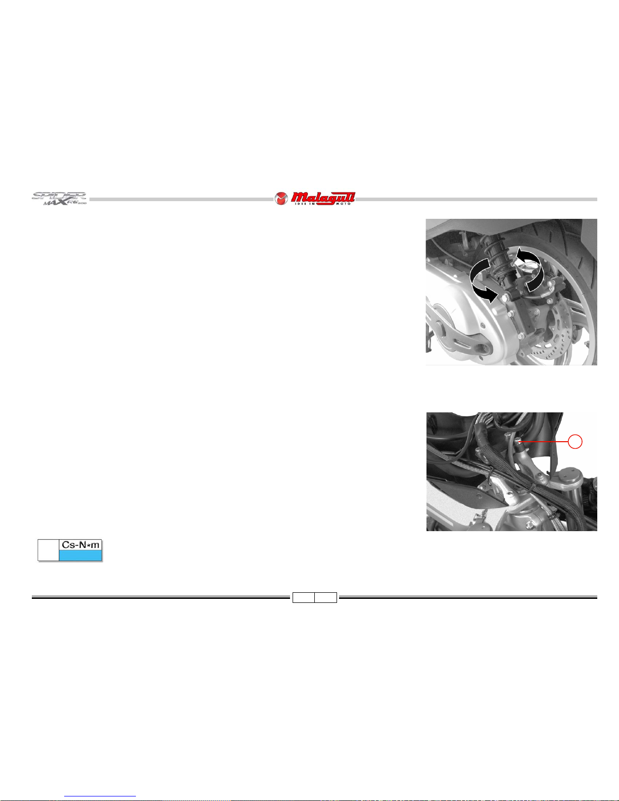
SPARK PLUG
REMPLACE
The spark plug is an essential component: NGK CR7EKB
Spark plugs with a heat degree different from the
recommended one may seriously damage the engine.
• The SpiderMax engine features an ignition system with a doub le spark
plug (C).
• For maintenance, remove the side partition (P), carefully remove the
cap by turning it clockwise and anticlockwise alternatively . Now , unscrew
the spark plug using the special wrench supplied with the vehicle.
Remove the spark plug when the engine is cold.
• Examine the spark plug conditions after a reasonably long drive (10-15
km) and after letting the engine cool down (at least 10-15 minutes),
since the sediments and the colour of the insulator can provide useful
information about the heat degree of the spark plug, carburetion,
lubrication and general conditions of the engine. If the insulator is
light brown around the central electrode, it indicates good working
order.
• Black, dry (to touch), sooty and tarnished deposits show that the
functioning temperature is too low (the heat rating of the spark plug is
too high), carburetion too rich or faulty ignition.
every 10.000 km
• Whitish insulating material shows an “e xtremely light” mixture or the heat rating of the spark plug too low (spark plug
too “hot”).
Check and clean every 6.000 km.
• After disassembling the spark plug, carefully clean the electrodes and the insulating material, using a metal brush. Adjust
the distance between the electrodes (operating only on the ground electrode), using a gauged shim: the distance should be
0.7 : 0.9 mm.
• Blow out energetically , to prev ent possible residues from entering the engine and refit it by tightening it by hand all the wa y
in; then, tighten it to the prescribed torque.
F . 33/a
12 ÷ 14
F. 3 3
Page 31

30 02/08
• Release the screws lower
(V3).
• Carefully remove the
central shield, paying
special attention in order
not to damage the locking
teeth.
• Disconnect the connector
(B) (parking light).
• Release the cable from the
bracket (C) and remove the
shield completely .
V2
A
V
V3
B
C
CENTRAL
FAIRING
• Release the screw upper (V)
PROCEDURES FOR DISMANTLING AND
REMOVING COMPONENTS
REASSEMBLY NOTE
REAR VIEW
MIRRORS
• Lift the rubber part (A) and
release the fastening screws
of the rear view mirror (V).
• Remove the rear view
mirror, complete.
V2
10 ± 20%
V3
1,5 ± 15%
V
1,5 ± 15%
F. 3 4
F. 3 5
F. 3 6 F. 3 7
FRONT DIRECTION
INDICA T ORS
(BULB CHANGE)
• The bulb holders of the front
direction indicators are integrated in the front headlights.
• To access the bulbs of the
front direction indicators, remove the inserted side covers (A).
A
Page 32

31 02/08
ACCESSES
(after removng the
central shield)
A) Control panel
B) Antilock
bracking
system
C) Beam light
adjusting
knobs
D) Horn
NOTE - The parking light bulb
is located inside the
central shield
• Remove the bulb and
replace by another of the
same type.
Reconnect the
connectors to test
the new bulb before
reassembling all
components.
• Remove the bulb
holder.
F. 3 8
F. 4 0 F. 4 1
REPLACING THE FRONT PARKING LIGHT
• Release the screws (V5).
• Release the screws (V2).
• Remove the cover (A).
D
C
B
A
F. 3 9
A
V2
V5
Page 33

32 02/08
F. 42
DASHBOARD
• Undo the screws (V4) and remove the control
panel carefully .
HORN
• Disconnect the two clamps (B).
• Release the screw (V) and remove the horn.
F. 43
V2
10 ± 20%
1,5 ± 15%
BRAKING DISTRIBUTOR
NOTE - To access the braking distributor (A),
remove the central fairing (P. 30).
Drain completely the circuit.
• Release the screws (V2).
V
10 ± 20%
• Undo the connectors (B).
• Remove pipes (C) and
gaskets (D).
B
20 ± 10%
F. 4 4
B
V
While reassembling, take care not to in vert the fitting of the Faston connectors. Blue
cable (+)lower terminal - Orange cable (-) upper terminal.
V2
A
C
B
D D
C
B
C
D
Page 34

33 02/08
AIR GRID
• After removing the cover of
the front parking light bulb,
you can remove the air grid
in order to clean it.
F. 4 5
WINDSCREEN
• Remove the central fairing
(p. 30).
• Release the screws(V3)
and remove the windscreen.
FRONT
FAIRING
NOTE - The front fairing is
made of two parts,
one right and one
left. The following
instructions apply
to the whole
fairing.
• Release the screws (V2).
• Release and remove the
lower screw (V1) and its
washer.
F. 47
V2
F. 4 6
F. 4 8
V3
V
V1
V1
1,5 ± 15%
• Release the screws (V4).
V4
1,5 ± 15%
V3
1,5 ± 15%
V2
1,5 ± 15%
• Release the central upper
screew (V).
V
5 ± 20%
Page 35

34 02/08
• Release the screws (V2)
and remove the passenger
footpeg.
• Remove the rubber mat.
V2
40 ± 15%
F. 5 0
F. 5 2
F. 4 9
F. 5 1
V2
• Release the screws
(V8).
• Release the half-fairing
upper part from the mirror mount, opening it up
carefully.
V8
1,5 ± 15%
Page 36

35 02/08
• Disconnect the two connectors (A) (direction
indicators).
• Disconnect the connector
(B) (front headlight).
• Remove the fairing.
ACCESSES
(after removing the two
front half-fairings)
Right half-fairing:
A) Immobilizer ECU
B) Side stand switch
connector
C) Fuel pump
- Right radiator
- Key switch
F. 5 3
F. 54
B
A
C
A
B
H
V2
Left half-fairing:
D) Expansion reservoir
E) Left radiator
F) Radiator fan
F. 5 5
E
F
D
IMMOBILIZER ECU
• Disconnect the three connectors (H).
• Release the screws (V2).
• Remove the Immobilizer ECU (A).
V2
10 ± 20%
If the Immobilizer ECU is replaced, store two or more ignition keys.
(please refer: DIA GNOSTICS MANUAL of the ELECTRICAL SYSTEM AND
EMS INJECTION SYSTEM, chapter “Immobilizer”).
Before refitting the different connectors, make sure if the inside sealing
rubbers (yellow) are worn out, and if the external ones are in the right
place. If these checks are not observed, in case of rain, the dashboard
may indicate improper warnings.
Page 37

36 02/08
SIDE STAND
SWITCH
• Release the screws (V2).
• Remove the switch (A).
• Open the front fairing.
• Disconnect the connector (B)
and detach the whole wiring
(if necessary), after releasing
its clips.
NOTE - While assembling a
new complete wiring,
refit new clips, placed
and fixed as before.
F. 5 7
F. 5 6
V2
V2
A
V2
5 ± 20%
B
C
F. 5 8
FUEL SUPPLY PUMP
• Disconnect the connector
(C - F. 57)
• The procedure to remove the
fuel supply pump (A) and its
float (B), can be understood
from the picture on the side.
• Check the conditions of the
gasket (C) and replace it, if
necessary.
• Carefully clean the mesh filter
(D).
NOTE - All of the inf ormation
on the pump can be
deducted by reading
the Manual “Injection”.
A
C
D
B
Page 38

37 02/08
F. 6 2
F. 5 9
F. 6 0
F. 6 1
RADIATORS
(including lines
and expansion
reservoir)
• Wait for the engine to cool
down completely .
• Put a suitable container
under the coolant pump (A).
• Remove the clip (B).
• Detach the tube (C) and fit
it in the container.
• Remove the cap (D - F. 60)
from the expansion
reservoir.
• In case radiators have to be
removed together with
lines, slacken the clip (B1)
and detach the tube (C1).
• Let the liquid completely drain into the container. Pour the spent
liquid in a container
suitable for its ecological disposal.
The coolant is
potentially polluting,
therefore it should
not be released in the
environment.
• Disconnect the connector of
the electrical fan wiring.
Release the bleed
screws (V) on both
the radiators,
releasing both
ground cable ends
(M).
• Cut all the clips securing the
lines composing the cooling
system circuit.
V
M
In case the pump (A) has to be removed, release the screws (V6).
• Cut the clip (E) securing the electrical fan wiring.
After refitting any of the components of the cooling system, fix the lines with new clips, in the same position as before, and fix the ground cable end
(M - F . 62) again, both to the right radiator as well as to the left radiator .
D
V6 CBA
B1
C1
E
Page 39

38 02/08
• Release and remove the
screws (V2) and their
washers.
• Remove the right
radiator.
RIGHT RADIATOR
• Release the lower securing
screw (V) of the right radiator (A).
• While reassembling,
first fit the radiators
on the upper silent
blocks.
NOTE - The radiators are fit-
ted on Silent blocks
(B); first release them
from the lower ones,
and then extract them
from above.
• Release and remove the
screws (V2) and their
washers.
F. 6 6
• Remove the left radiator ,
including the electrical fan.
LEFT RADIATOR (including
the electrical fan)
F. 6 3
F. 6 5
F. 64
V
10 ± 20%
V2
10 ± 20%
V2
10 ± 20%
B
B
A
V
V2
B
V2
Page 40

39 02/08
F. 6 7
F. 6 9
EXPANSION
RESERVOIR
Drain the coolant from
the circuit, as previously
described.
• Disconnect the tube (C) from the
expansion reservoir.
• Release the screws (V2).
THERMAL
EXPANSION VALVE
NOTE - The cooling system
includes two thermal
expansion valves:
A - Thermal expansion
valve for the right
radiator
adjustment
• To remove it, release it
from the clips (F) and slide
it from the support (S).
ELECTRICAL FAN
RADIATOR
• Release the screw (V) and
remove the expansion
reservoir.
V2
10 ± 20%
V
10 ± 20%
V2
C
F. 6 8
V
A
S
F
F. 70
B - Thermal expansion valve on the engine
• T o remove it, release it from the clips of the rubber hoses and slide it from the support
(S).
S B
Page 41

40 02/08
F. 7 1
KEY
SWITCH
• Disconnect the seat opening
transmission cable (A).
• Disconnect the helmet compartment opening transmission cable (B).
• The key switch (C) is fitted
by two nuts (D) and two “antitampering” screws (V2), that
can be accessed from the
lower part of the switch body .
To disassemb le the
key switch, use the
special insert: “T orks
t 30” for special
screws.
cod. 08606600
F. 7 2
Take care not to
damage the cables
during the operation.
Squeezing or cuts of
some of the fibres of
the cables imply their
complete
replacement.
• Disconnect the two-way connector connected to the Immobilizer.
DASHBOARD
PANEL
• Release the screws (V2).
• Remove the dashboard
panel (A), releasing it from
the locking tabs.
F. 7 3
V2
V2
B
A
V2
C
D
V2
If the key switch is replaced, or all of the stored keys are lost, replace the
Immobilizer ECU as well, and store new keys. To store a third key, use the
“Master key” (cod. 09007000) (please ref er: DIAGNOSTICS MANU AL of the
ELECTRICAL SYSTEM AND EMS INJECTION SYSTEM).
Page 42

41 02/08
F. 7 4 F. 7 5
F. 7 6 F. 7 7
LEG
PROTECTOR
• Remove the key switch ring
nut (A) rotating it counterclockwise.
• Release the retaining
screws (V2) of the fusebox.
• Remove the transparent
cover.
• Push forward the fusebox
• Release the screw (V).
• Release the three screws
(V) inside the luggage
compartment.
• Release the screw underneath (V1).
V1
5 ± 20%
V
5 ± 20%
V
V1
V
V2
Page 43

42 02/08
F. 7 8 F. 7 9
F. 8 0
V3
5 ± 20%
F. 8 1
• Release the screws (V3). • Unlock the luggage compartment closing transmission cable from its seat (A).
• Open slightly the footpeg
until the plastic locking tabs
are released.
• Extract the leg protector
assembly , together with the
footpegs.
V3
Page 44

43 02/08
• Remove the footpeg if
necessary, release the
screws (V2).
ACCESSES
(after removing the upper
handlebar cover)
B) Main wiring end
V4) Handlebar inclination
adjusting screws.
V2
1,5 ± 15%
V2
1,5 ± 15%
F. 8 4
F. 8 2 F. 8 3
UPPER HANDLEBAR
COVER
• Release the screws (V2) and remove
the upper handlebar cover (A).
F. 8 5
V2
V2
A
B
V4
Page 45

44 02/08
F. 8 6
F. 8 8
• Release the outside screws
(B2) and remove the front
handlebar cover (A).
• Release the remaining four
inside screws and remove
the rear handlebar cover
(P).
FRONT AND REAR
HANDLEBAR
COVER
• Release the upper screws
(V2).
ACCESSES
• Removing the front handlebar
cover allows to reach the two
brake liquid pumps (A) and
the two stop switches (B).
V2
V2
1,5 ± 15%
B2
1,5 ± 15%
F. 8 7
P
B2
A
B
A
B
A
Page 46

45 02/08
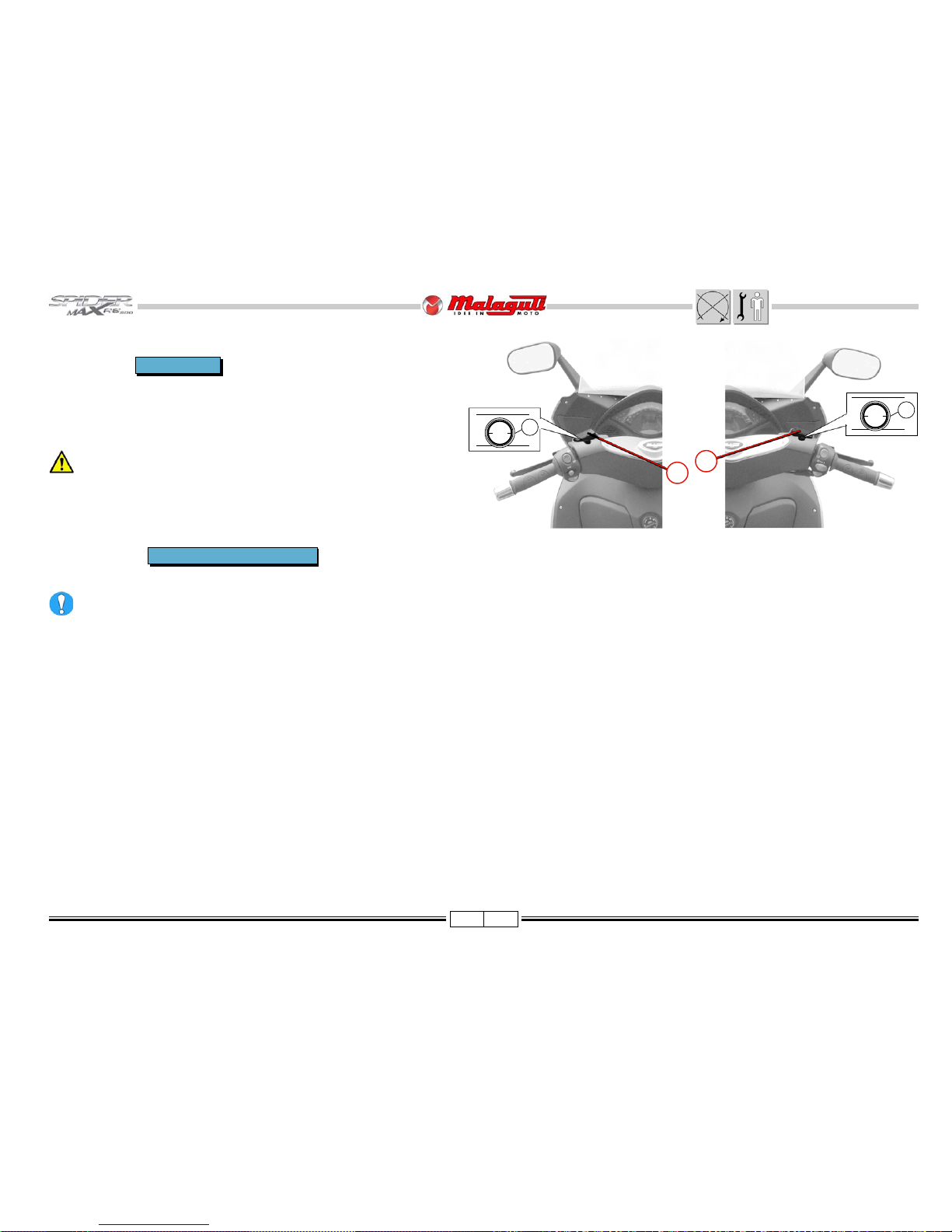
BRAKE MASTER
CYLINDERS
Empty the hydraulic
system and dispose of
the liquid in compliance
with the law in force.
Ensure that there are
no leaks or splashes
of brake liquid, as it is
corrosive and may
cause personal injury
or damage the
motorcycle painted
parts.
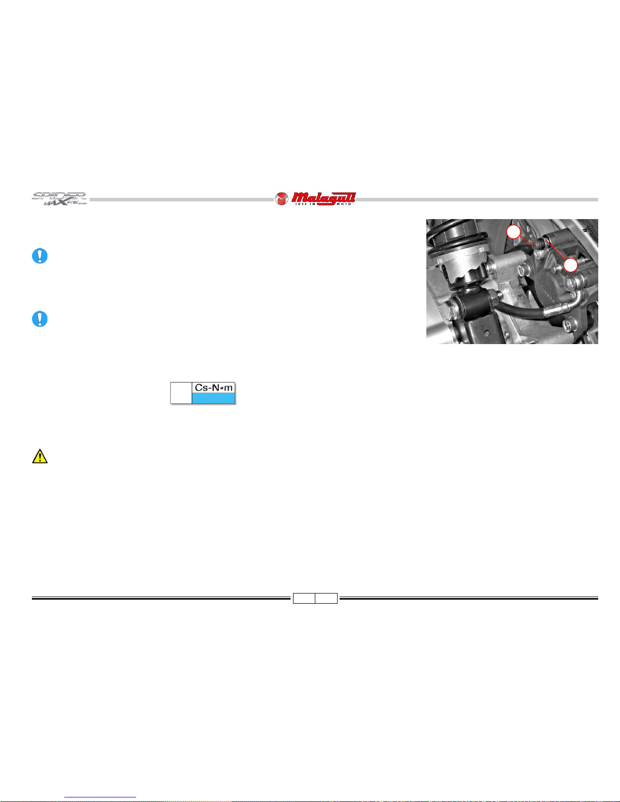
• Release the screws (V2) and
remove the clamp (D).
• Remove the pump unit (E).
• In order to reassemble the
unit lock (by means of a long
T-wrench) the lower screw,
without tightening it, and then
the upper screw; finally tighten both of them to the
specified torque.
NOTE- After reassembling the hydraulic pump, always refill the system with new
liquid.
V2
28 ± 15%
A
20 ± 10%
F. 9 1
• Release and extract the coupling (A).
• Remove the tube (B) and the gaskets (C).
• Disconnect the Stop switch (S).
NOTE - Repeat the same procedure for both brake pumps.
S
B
A
C
HANDLEBAR
To remo ve the handlebar:
• Remove the handlebar cover: upper, front and rear
(P. 4 4).
• Cut the clips securing wiring, tubes, and cables.
• Remove the (right and left) brake master cylinders.
• Release the transmissions from the accelerator con-
trol (B).
• Release the two counterweights (P).
• Detach the two twistgrips (M).
• Release the two switches (D).
• Release the screws (V4).
• Remove the plate securing the handlebar (A).
• Remove the handlebar (C).
Tighten in a criss-cross pattern.
V4
30 ± 20%
After assembling the
(front/rear) brake
master cylinder, fit
the tube (B) between
two new gaskets (C)
And tighten the
coupling A to the
specified torque.
F. 9 2
V2
E
A
B
D
C
F. 8 9
V4
F. 9 0
B
P
M
D
P
M
D
A
V4
C
Page 47

46 02/08
F. 9 3
F. 9 4
DRIVER
SEAT
• Release the screws (V2) on
the rear part.
• Remove the driver seat (A),
releasing it form the locking
tab (B).
V2
5 ± 20%
V2 A
ACCESSES
• Removing the driver seat,
allows reaching the following
electronic components:
A) Relay (black) - Starter
B) Relay (yellow) - Electric
fan
C) Relay (red) - Injection
system
D) Tilt sensor connector
E) Tilt sensor
F) Flasher
B
NOTE - In order to access the
tilt sensor (E) it is necessary
to remove the rubber protection (G).
When reassembling the
sensor, make sure that
the cable (H) is facing
downwards.
F. 9 6
G
A
B
F. 9 5
E
F
CD
H
Page 48

47 02/08
F. 97
F. 9 8
PASSANGER
SEAT
(including
movable support)
• Remove the Benzing ring (C)
and release the passenger
seat shock absorbers.
• Release the screws (V2)
from the front supports.
• Remove the seat together
with the grab handle and
movable support.
• In order to release the
passenger seat (F . 49) from
the movable support, first
release the screws (V6).
CUSHION DRIVER SEAT
• Release the screws (V2).
Slackening the screws (V2) allows adjusting
the cushion travel according to the user’ s
requirements.
GRAB HANDLE
• Release the screws (V5) and remove the grab handle
(D).
D
C
V2
V5
30 ± 15%
V2
10 ± 20%
V6
10 ± 20%
V5
V2
V5
V6
F. 9 9
Page 49

48 02/08
F. 100
F. 1 01
F. 102
F. x x
• Disconnect the 12V plug cable from the back of the helmet compartment.
HELMET
COMPARTMENT
• Extract (without any tool) the
compartment inside coating.
• Release the screws (V).
• Release the screws (V2a).
V2a
F. 1 03
DIRECTION INDICATORS AND TAIL LIGHTS (BULB CHANGE)
• Lift the seat.
• Removing the inserted side covers (A), allows reaching the rear direction indicator
bulbs.
• Removing the inserted rear covers (B), allows reaching the tail light bulbs.
V2
5 ± 15%
V4
10 ± 20%
V2a
5 ± 15%
• Release and extract carefully the helmet compartment without removing it
completely.
V2a
• Release the screws (V2).
• Release the screws (V4).
V2
V4
V4
B
A
V
1,5 ± 15%
V
Page 50

49 02/08
REAR
FAIRING
• Release the two screws (V2).
• Release the screw (V).
F. 104
• Lift the helmet compartment,
disconnect the connector (A)
and release the cable from
the clamp (B).
• Remove the helmet compartment completely .
F. 105
V
5 ± 15%
V2
5 ± 15%
Page 51

50 02/08
F. 106
F. 1 07
F. 108 F. 109
• Release the screws (V4). • Extract the entire fairing to-
gether with the tail lights.
TAIL LIGHTS
• Tail lights can be accessed by
removing the helmet compartment and the rear fairing.
• Disconnect the wiring.
• Release the screws (V3).
• Remove the cable clamps (A).
• Remove the headlight
concerned.
While reassembling,
refit the cable clamps
as before.
The tail lights glass
cannot be replaced.
If it is broken, replace
the whole headlight.
A
V3
V4
1,5 ± 15%
• Keep the rear fairing
components far from heat
sources, in a clean place
where they cannot be
accidentally damaged.
V4V4
Page 52

51 02/08
SIDE REACH (after
removing the rear
fairing)
• Removing the rear fairing
allows reaching the following
components:
Right-hand side
A) Voltage regulator
B) Coolant pump
C) (T ree-phase) stator
connector
D) Ground ends
F. 110
Left side
A) Coil
B) Ground ends
F. 1 11
C
B
A
B
C
V4
VOLTAGE REGULATOR
• Release the screws (V2).
• Remove the wiring cable ends from the right
screw.
• Remove the voltage rectifier (A).
• Disconnect the flywheel connector (C) and the
connector (F) located underneath the wiring
protection sheaths
COIL
• Disconnect the connector (C).
• Release the screws (V4).
• Remove the coil (A).
COOLANT PUMP
See Service Manual (Section “C”).
M
DA V2
F
Page 53

52 02/08
• Disconnect the connector of the
anti-tilting device.
F. 112
• Release the rear screw (V1).
F. 1 13
• Release the two front screws (V2).
V2
RELAY HOLDER
• Extract the starting relay (C), including the
30A fuse (battery recharge protection).
If the starting relay is replaced, take
special care to the assembly of the
red and blue cable (Please refer:
DIAGNOSTICS MANU AL of the
ELECTRICAL SYSTEM AND EMS
INJECTION SYSTEM).
F. 114
V1
V2
C
F. 1 15
C
Page 54

53 02/08
ACCESSES
A) Injection ECU
B) Injector
C) Motor temperature sensor
NOTE - All of the information concerning these com-
ponents can be deducted by reading the DIAGNOSTICS MANUAL of the ELECTRICAL
SYSTEM AND EMS INJECTION SYSTEM.
ELECTRONIC
INJECTION ECU
THROTTLE BODY
• T o remo v e the ECU see the Electric
System Diagnostics Manual
(Section“B”).
F. 116
B
C
1
A
•After disconnecting all
connectors, remove the relay
holder (1) on one side or
remove it completely.
F. 1 17
Page 55

54 02/08
BATTERY
COMPARTMENT
• Remove the fuel filler cap
(A).
• Release the screws (V2).
• Extract the dripproofing
protection (B) and the drain
hose.
• Remove the battery compartment cover.
• Release the screw (V) at the bottom of the battery compartment and remove the
compartment, extracting the battery cables and fusebox.
ACCESSES
• Removing the battery compartment, allows reaching the starting relay and the
corresponding 30 A fuse (recharge protection).
F. 118
F. 121
F. 120
NOTE - Inside the battery com-
partment, is located
the general protection
fuse (F) (30 A).
• Release the battery cables.
• Extract the battery.
F. 1 19
V
10 ± 20%
F
B
A V2
V
Page 56

55 02/08
F. 1 25F. 124
• Release the screws (V4).
To remo ve the tank,
proceed as follows:
• Remove the battery and the
whole compartment (P. 54).
• Remove the cap (A).
• Extract the dripproofing protection (B) and its tube (C).
• Refit the original cap on the
fuel filler, to prev ent dirt from
entering the fuel tank, during
the frame removal operations.
FUEL TANK
NOTE - To access the fuel tank, first remove the front fairing (P. 33).
Fuel fumes are highly toxic, and therefore harmful to your health. V entilate
the room before proceeding and, if necessary , wear a protection mask.
Do not remove the tank, unless the latter has been previously emptied.
Do not smoke, nor use bare flames. Do not carry out any the operation while
working and producing sparks (such as welding, grinding, etc.).
• Remove the connector (1)
from the fuel pump,
pressing by two fingers at
the base of the connector.
F. 1 23
F. 122
T V4
V
A
C
B
To drain the tank, w ait
for the engine to cool
down completely and
use a manual pump.
1
V4
10 ± 20%
Page 57

56 02/08
• Disconnect the tube (C).
• After extracting the tank, release the screw (V), releasing
it from the support (T).
• Extract the tank, sliding it
from the front side of the
frame, downwards.
• Disconnect the connector (A)
of the fuel pump.
• The fuel tank is blocked, in
its rear side, by the two
Silent Blocks (B).
A
T
V
C
F. 126
F. 128
F. 1 27
F. 129
C
B
Page 58

57 02/08
AIRBOX
• Release the screws (V8) and
remove the cover (A).
• Release the hose (B) from
the throttle body .
• Extract the airbox.
• Release the gas recovery
hose (C).
F. 130
F. 1 31
F. 132
A
V8
C
C
B
Page 59

58 02/08
WHEEL SPINDLE
• Slacken the screw (V1)
from the wheel spindle
clamp.
• Release the wheel spindle
(B) and extract it, taking
care not to damage spacer
(C) and the spacer (B1).
FRONT WHEEL
REMOVAL
Before removing the
front wheel, check for
the perfect stability of
the motorcycle. If necessary, place one suitable support under
the engine.
FRONT
MUDGUARD
• Release the screws
(Va)
• Release the screws
(Vb) and corresponding
nuts (A).
F. 133
Vb
3,5 ± 10%
Va
3,5 ± 10%
F. 1 34
F. 135 F. 136
Do not actuate the
brake levers without
the wheel, as the pads
would close.
• Release the screws (V2) and release the entire callipers.
• Release the screw (V) and extract the odometer sprocket (A).
B1
B
C
V1
B
Va
A
Vb
Va
V
V2
A
V2
30 ± 20%
Vb
Page 60

59 02/08
FRONT WHEEL
REASSEMBLY
When reassembling the wheel, observe
rotation direction, which can be determined
by the position of the spokes of the rim (see
previous pictures).
T o reassemble the wheel, proceed as f ollows:
• Insert the wheel in the fork (in the proper direction).
• Insert the wheel spindle (B) and the spacer (B1).
• Insert the spacer (C).
Do not exchange the spacer (B1) with the
spacer (C).
Tighten the spindle (B) to the specified torque.
(FRONT BRAKE)
DISCS
• T o separate the discs (D) from the front wheel,
release and remove the screws (V6) and the
washers (E).
Check the discs (D) for wear and replace if
necessary (service limit 4.5 mm). In case of
abnormal wear or signs of scoring, carry out
grinding.
When reassembling the (right and left
brake) discs observe disc rotation
direction, which can be determined by
the position of the slots.
B
45 ± 15%
V6
11 ± 10 %
F. 137
D
V6
E
E
V6
D
• Tighten the screw
(V1) of the wheel
spindle clamp.
F. 141
• Refit the odometer
sprocket (pick-up)
(A) and secure it by
means of the screw
(V).
V
10 ± 15%
V1
20 ± 15%
F. 138
F. 140
B1
B
C
F. 139
A
V
V1
Page 61

60 02/08
BRAKE
CALLIPERS
An abnormal resistance
or an excessive travel
of the brake levers may
indicate the braking
system malfunctioning.
• Open up the clamp (F).
• Undo the screws (V2) in order
to release the fork clipper.
FRONT CALLIPER
REPLACEMENT
NOTE - The front callipers
have the same technical
specifications but are one
right and one left.
• After removing the front
brake callipers, release
the screw/coupling (V) and
extract the swinging
coupling (A) and the
gaskets (B).
Do not use the brake lever after removing the callipers: the piston may
jump off, causing brake liquid leaks. The liquid is corrosive and may
cause serious personal damage.
After removing the callipers from their housing, place a container
underneath in order to let the liquid drain from the hydraulic system and
dispose of it in compliance to the law in force.
V2
30 ± 20%
FRONT CALLIPER
DISASSEMBLY
In order to extract the pads:
• Release and remove the
screw (V).
• Shift downward the stop
plate (A), in order to release
the pins (B) and extract
them from the other side of
the calliper unit.
V
20 ± 10%
F. 142
V
F. 144 F. 145
A
B
F. 1 43
A
V
B
B
V2
F
V
A
Page 62

61 02/08
• Remove the stop plate. • Extract the pins (B).
• Extract the pads.
NOTE - It is possible to
remove and replace
the pads without
removing the brake
callipers from the
vehicle.
• Release the nut (D - F. 146).
• Remove the floating support (S) from the calliper
body , including the two
slide pins.
During reassembly ,
lubricate the slide pins
must rubber gasket
grease.
D
20 ± 20%
F. 1 47
F. 146
F. 148
F. 1 49
D
S
B
B
Page 63

62 02/08
• Check the dust seals (P - P1)
for wear. In case of signs of
(even light) wear or damage,
replace them.
• Open by means of a screwdriver (or any other similar tool),
the bracket (B) fins (A). Remember to wear safety gloves.
• Release the screws (V2).
• Remove the plate (C).
After refitting the plate
(C) and the bracket
and tightening the
screws (V2) to the
specified torque, lean
the fins (A) as before
(Please refer: F. 144).
• Blow with a small compressed air flow to extract the
two pistons from the
calliper body .
An excessive pressure may cause
the two pistons (E) to jump off
violently .
After servicing the braking system, always check that:
• The brake liquid tubes are not damaged, squeezed or twisted.
• The brake discs and pads are not soiled with oil or grease;
• All the screws and couplings are properly tightened.
• There are no leaks from the couplings.
• Remove the dust seal (A) and the seal ring (B) from both the
pistons.
During this operation, take care not to damage the dust
seal and seal ring housing.
• Make sure there are no signs of scoring on the pistons and their
housing.
• Clean carefully and wash only with alcohol.
Always use new dust seals and seal rings.
Refit the pistons, the seal rings (B) and the dust seals (A),
greasing with brake liquid.
Complete the check, clean, replace and refit all the
components repeating the disassembly operations in the
reverse order .
F. 1 53F. 152
F. 150
F. 1 51
B
A
C
A
P
V2
P1
E
E
Page 64

63 02/08
V
30 ± 25%
FORK
STANCHION GR OUP
Make sure that the motorcycle is really stable; in case, put a suitable support
under the engine. The front wheel will ha ve to protrude over the runawa y
edge of the lift.
ST ANCHION DISASSEMBL Y
Lock the stanchion
group in a suitable
vice, carefully
protecting the slider
side with soft jaws, as
to avoid squeezing or
scoring.
• Release the upper screw (V2).
• Detach downwards the fork leg
(A), rotating it in the two directions.
NOTE - To remove one or both of the legs
of the front fork, completed with
stanchion, first remove:
• front fairing
• (front/rear) handlebar cover
• (right-hand side) odometer sprocket
• Front wheel
• brake callipers
• front mudguard
• Release the screw (V).
NOTE - The disassemb ly of the
stanchion can be deducted
from the picture shown hereafter.
CHECK THE OIL LEVEL IN THE
ST ANCHION
If there is the “limit switch” of the front
fork, or irregular noise, check the oil level
inside the legs of the fork, proceeding as
follows:
• Release the upper cap (A).
• Remove the O-Ring (B).
• Carefully remove the spring (C) and let
it drip off completely the oil in which it
was previously plunged.
• Bring to the limit (downwards) the leg,
keeping it in perfect vertical position.
F. 156
F. 154
LOWER FAIRING
MUDGUARD
NOTE - T o remove the lo wer
fairing mudguard, first
remove the front
wheel and the front
mudguard.
F. 155
V2
A
V2
20 ± 15%
A
20 ± 15%
F. 157
V
C
B
A
V
The stanchion group contains oil. Therefore, do not turn it over or tilt it
while it is removed or its internal components are disassembled.
The hydraulic oil is corrosive and may cause serious personal
damages.
Page 65

64 02/08
COMPLETE FORK
Place a suitable support under the engine. The front wheel will have to pr otrude over the runa way edge of the lift , so
that the fork can be removed, together with the wheel, if necessary (in order to remove the front fork, the front wheel does
not have to be removed).
NOTE - To remove the complete fork, first remov e:
• front fairing (P. 33)
• front mudguard (P. 58)
• Front wheel (optional) (P. 58)
• brake callipers (optional) (P. 60)
• handlebar (P. 46).
•
Release the nut (D), release the screws (V2) and detach the unit (T).
•
Release the ring nut (E).
•
Detach the complete fork, holding it to avoid its falling.
•
T ak e care not to let the upper (F) and lower (G) ball bearings f all off.
V
30 ± 15%
• Using a meter or the stick of a gauge,
check the proper oil level, which should
be at mm 123 from the upper edge of
the leg.
• If necessary, top up with oil:
Q8 FORK OIL
• Before refitting the front fork, clean all the components, eliminating any sign of grease.
• Check the conditions of the components, and replace them, if necessary .
• Grease the ball bearings and their seats and reassemble the front fork.
Quantity per leg 385 cc
F. 160
D
T
V2
E
F
G
Sfere superiori C = n° ... Ø ...
Sfere inferiori D = n° ... Ø ...
Upper ball bearings F = n° 18 Ø 1/4”
Lower ball bearings G = n° 18 Ø 1/4”
D
18 ÷ 20
F. 158
F. 159
V
V
E
53 ± 15%
FRONT FORK OIL REPLACEMENT
• Place a suitable container under the stanchion and remove
the screw (V).
• Allow as much oil as possible to drain out.
• Disassemble the stanchions, as previously described.
• T urn ov er the stanchion, to let the remaining oil drain out.
The hydraulic oil is corrosive and may cause personal
damages.
• Do not dispose of spent oil in the environment.
• Refit the drain screw (V).
• Carefully pour the new oil in the leg.Carefully pour the new oil in the leg.
• Check the oil level, as previously described.
• Refit the components of the legs and the legs themselves on the
motorcycle.
Page 66

65 02/08
EXHAUST
Before operating on
the exhaust and on
the exhaust manifold,
wait for the
components to cool
down and wear,
always and in any
case, suitable safety
gloves.
•Vb.
• Release the clamp (F)
and remove the exhaust
pipe.
• Slacken the screw (V) of
the clip securing the
exhaust/exhaust manifold.
•Va.
Vb
14 ÷ 15
F. 161
F. 1 62
F. 163 F. 164
Va
V
Vb
B
• Release the Lambda sensor
cable from the clamp (B).
V3
A
Va
25 ± 15%
F
EXHAUST
MANIFOLD
• Undo the screws (V3)
of the heat guard (A).
• Remove the grid.
Page 67

66 02/08
• First remove the relay
holder (P. 52).
• Disconnect the Lambda
sensor connector.
• Release the two nuts (C).
• Remove the exhaust
manifold (D).
• Remove the gasket.
F. 165
While reassembling,
always use a new
gasket.
F. 1 66
C
30 ± 10%
C
D
LAMBDA SENSOR
Removal
• Slacken the Lambda sensor
(A) from the exhaust
manifold using a suitable
locking system in order not
to damage the manifold.
F. 168F. 167
A
Reassembling
• Screw the Lambda sensor
down with along cable and
connector.
• Tighten to the prescribed
torque.
A
45 ± 15%
Page 68

67 02/08
REAR SHOCK
ABSORBERS
Before carrying out any
operation in the rear
shock absorbers,
prepare a system
ensuring the vehicle
perfect stability even
without shock
absorbers.
F. 169
•V2I
•V2S
F. 171
F. 170
During both the removal and the
reassembly of the rear shock absorbers,
remember that the lower and the upper
screws have washers (R) and nuts (D).
V2I
V2S
V2I
V2S
V2S
R
D
D
D
D
R
R
R
R
V2I
V2I
30 ± 15%
V2S
45 ± 15%
V2I
Page 69

68 02/08
Remove:
• Exhaust pipe (P . 65)
• Right shock absorber (P . 67)
• Right abosorber upper plate
(P - F. 176).
•B2
REAR ARM
Before removing the rear arm (A), check that the vehicle is in perfectly
stable conditions.
Remove:
• Anti-vibration O -Ring (1)
• Spilt pin (2)
• Cover (3)
• Release the underlying nut
(D).
• Remove the shim (S) and
release the arm (A - F . 175).
B2
33 ÷ 41
D
100 ± 15%
When removing and
reassembling the
upper arm, make sure
the spacer (E)
orientation is correct.
SHOCK ABSORBER
SUPPORTING
PLATE
Right plate
• Release the right shock
absorber (P. 67).
• V2.
• Remove the plate (P).
F. 172
F. 175 F. 176
E
F. 173
F. 1 74
1
2
3
S
D
1
2
3
B2
P
A
V2
30 ± 10%
V2
Page 70

69 02/08
B
A
C
D
D
B
Left plate
• Release the left shock
absorber (P. 67).
• V2.
• Remove the plate (P).
F. 179
F. 178
V2
30 ± 10%
V2a
30 ± 20%
V
20 ± 10%
REAR CALLIPER
• Release the screws (V2a).
• Extract the calliper unit (A), including the brake liquid
feed tubes.
• Release the coupling screw (V) and extract the coupling
(A) and the gaskets.
After removing the callipers from their
housing, place a container underneath to let
the hydraulic system liquid drain, and dispose
of it in compliance with the law in force.
V2
V2a
A
V
F. 177
• Let a little compressed air in, so as to let the two pistons
out of their seats in the two housing halves composing
the calliper.
C
D
REAR CALLIPER
DISASSEMBLY
• Remove the retaining ring (A)
of the spindle securing the
brake pads (B).
• Detach the spindle securing
the brake pads (B).
• Extract the clip (C) and the
two brake pads (D).
P
Page 71

70 02/08
F. 180
• Release and remove the
screws (V2).
• Separate the two housing
halves, taking care not to
let the two pistons fall.
• Remove the two pistons (D).
• Remove the two O-Rings (E).
F. 181
V2
20 ± 20%
D
E
D
E
V2
F. 182
Always fit new seal
rings and dust seals.
Refit the pistons, the
O-Rings, the seal rings
and the dust seals,
lubricating with brake
liquid.
• Remove the dust seal (A) and the seal ring (B) in both the housing halves, taking care
not to damage their seats.
• Check that the pistons and their seats are in perfect conditions.
At the end of each operation on the braking SYSTEM, always check that:
• The brake liquid lines are not damaged, squeezed or twisted.
• The disc and the brake pads are not soiled with oil or grease.
• All the screws and couplings are properly tightened.
• There are no leaks from the couplings.
Page 72

71 02/08
F. 185
ENGINE
NOTE - To remove the
engine from the
frame, first remove
rear fairing (P . 49),
exhaust (P. 65),
rear arm (P . 68),
rear brake calliper (P. 69).
• Drain completely the
coolant circuit.
• Disconnect all the wirings
connected to the engine.
• Release the screws (V2)
(double ground screws on
the starter motor).
F. 186
Do not cut nor damage the transmission cables of the accelerator control,
since they are not to be replaced during the reassembly of the engine.
V2
B
A
REAR WHEEL
NOTE - To extr act the rear
wheel, first remove
the brake calliper,
and the exhaust.
• Release and remove the
screw (V) securing the right
shock absorber, on the rear
arm.
• Remove the washers and the
nut.
• Once the shock absorber has
been released, move it
upwards and hold it, so that it
will not impede the subsequent operations.
F. 183
V
(REAR BRAKE) DISC
During the check and the
service on the rear brake
calliper, check the disc
conditions (C). If the disc is
too worn out, (service limit
3.5 mm), replace it,
releasing and removing the
screws (V6), including their
washers (D). In case of
irregular wear or scoring,
carry out the grinding.
• Disconnect the
accelerator transmission cables
(A).
• Disconnect the
manifold linked to
the connector (B)
from the thermal
expansion valve.
V6
11 ± 10%
V6C
D
F. 1 84
During the disc reassembly , observe the rotation direction of the disc,
understandable from the orientation of the lightening holes (as shown in
pictures).
• Remove the rear arm, as described in the previous page 68.
• Extract the rear wheel.
Page 73

72 02/08
• Slacken the clips (A) and
release the coolant manifolds from the pump.
F. 187
D
65 ± 15%
D
P
A
F. 190
B
A
C
D
ENGINE MOUNT
T o remov e the engine
mount (A) (after removing the
engine), proceed as follows:
• Release the self-locking nut
(B).
• Slacken the lock nut (D).
• Release the threaded
bushing (C).
While reassembling, do not exchange spacer (B) with spacer (C).
F. 189
B
C
F. 1 88
• Release the nut (D) of the engine shaft.
• Detach the engine shaft (P).
• Extract carefully the engine, using safety gloves and an assistant.
Support suitably the
engine with systems
ensuring both the
top safety for the
operators during the
removal, as well as
the perfect stability
of the vehicle, before,
during and after the
operation. Bear in
mind that only the
left shock absorber
will be kept “active”,
once the engine will
be removed.
Place the coolant
manifolds so that
they will not
impede the
engine removal,
taking care not to
bend nor damage
them.
ENGINE
REASSEMBLY
• Lubricate the spacers
(B - C) and the shaft
(P - F . 187) with bearing
grease
• Align the engine to the
engine shaft (P).
• Fit the engine shaft (P).
• Fit the nut (D) up to get
to the prescribed torque.
Page 74

73 02/08
B
35 ± 15%
F. 191
F. 1 92
C
10 ± 15%
V
65 ± 15%
• Detach the (upper)
mount shaft (E).
• Remove the engine
mount and the spacers.
While
reassembling,
take care not to
interfere and
exchange the
spacers, which
will have to be
lubricated with
bearing grease.
ANTI-VIBRATION
CONNECTING RODS
• After removing the
engine and its
mount, release the
nut (F - F. 193).
• Remove the screw (V) and
the washer (G).
• Remove the anti-vibration
connecting rods (H).
ENGINE MOUNT
• Place the mount (A) inside the frame.
• Fit the shaft (E).
• Fit the threaded bushing (C) including the lock nut (D) to the frame, taking care to
observe the prescribed torque.
• Fit the lock nut (D), tightening it completely to the frame.
• Fit the self-locking nut (B), tightening it to the prescribed torque.
If the bushing (C) was tightened too much, it may cause annoying
vibrations to the vehicle and irreparable damages to the bearing (U).
V
F. 193
X
Y
X
Y
G
V
H
F
A
C
D
B
U
E
E
Page 75

74 02/08
SUBFRAME
NOTE - The subframe is
made up of three
parts:
1 - Upper subframe
2 - Right-hand side subframe
3 - Left-hand side subframe
• T o remov e the subframe
from the central aluminium
frame, first remove all the
components described up
to this paragraph.
• Cut all the clips from the
subframe and release the
different wirings.
• Disconnect the connectors
of the electrical components to be removed.
• Disconnect the connector
(A) from the switch placed
on the side stand.
• Remove the immobilizer
ECU (B) (P . 35).
• Release the screw (V) and release the lines of the
brake oil (D - E).
• Remove the braking distributor (F) ( P. 32).
F. 194 F. 195
A
B
V
10 ± 20%
V
F
ED
Page 76

75 02/08
UPPER SUBFRAME
• Release and remove the two screws (V) and their washers.
• Release and remove the screws (V2) and their washers.
• Separate and extract the upper subframe (1) from the two side subframes.
SIDE SUBFRAMES
• Release and remove the lower screw (M8) and its w asher.
• Release and remove the lower scre w (M10) and its washer.
• Release and remove the screws (V3) and their washers.
• Remove the side subframes.
NOTE - The left subframe can be removed together with its side stand.
CENTRAL ALUMINIUM FRAME
NOTE - The aluminium frame (4), is made up of the two symmetrical parts.
• Release (on both sides) the screws (V4) securing the aluminium frame to the rear
frame.
• Release the central screws (V2a) and remove the spacer between the two half-frames.
• Release the lower screws (V2b) and remove the spacer (A).
• Release and remove the upper screws (V6) with their washers and nuts. Moreover these
screws secure the headstock (B).
• Separate the two aluminium “half-frames“.
F. 196
V2a
V2
B
4
V
V4
V2b
V3
V3
M10M8
A
V6
1
2
3
V
10 ± 15%
V2
10 ± 15%
V2a
60 ± 15%
V2b
60 ± 15%
V3
25 ± 15%
V4
60 ± 15%
V6
25 ± 15%
M8
25 ± 15%
M10
55 ± 15%
Page 77

76 02/08
FRAME DIMENSION CHECK
• If the motorcycle has had an accident, which “appear” to ha ve caused a distortion, even light of the frame, carry out a dimension check, bef ore any other “restor ation and set up”.
• The pictures hereafter show the check dimensions.
The dimension measured may have a ± 2 mm tolerance. Otherwise, replace completely the frame.
Do not distort the frame to restore the original dimensions.
F. 197
Page 78

77 02/08
CABLE POSITIONING, “PIPE SYSTEM” AND ANCHORING TIES
F. 198 F. 199
Page 79

78 02/08
F. 200
Page 80

79 02/08
F. 201
Page 81

80 02/08
F. 202
 Loading...