

Page 1
EM2650UH/EM2650LH
GB Brushcutter & String Trimmer
F Débroussailleuse Thermique
E Desbrozadora
INSTRUCTION MANUAL
MANUEL D’INSTRUCTIONS
MANUAL DE INSTRUCCIONES
EM2650UH EM2650LH
Important:
Read this instruction manual carefully before putting the Brushcutter & String Trimmer into operation and strictly
observe the safety regulations!
Preserve instruction manual carefully!
Important :
Lisez attentivement les instructions du présent manuel avant de vous servir de la débroussailleuse thermique
pour la première fois, et respectez à la lettre les consignes de sécurité!
Conservez précieusement ce manuel d’instructions!
Importante:
Lea esta manual de instrucciones con atención antes de utilizar la desbrozadora y ¡observe estrictamente las
regulaciones de seguridad!
¡Conserve cuidadosamente su manual de instrucciones!
Page 2
English
(Original instructions)
Thank you very much for purchasing the MAKITA Outdoor Power Equipment.
We are pleased to recommend to you the MAKITA product which is the result of
a long development program and many years of knowledge and experience.
Please read this booklet which refers in detail to the various points that will
demonstrate its outstanding performance. This will assist you to obtain the best
possible result from your MAKITA product.
SYMBOLS
You will note the following symbols when reading the instructions manual.
Read instruction manual and follow
the warnings and safety precautions!
Table of Contents Page
Symbols .........................................................................2
Safety instructions .........................................................3
Technical data................................................................7
Designation of parts.......................................................8
Mounting of handle ........................................................9
Mounting of protector...................................................11
Mounting of cutter blade or nylon cutting head............12
Before start of operation ..............................................13
Correct handling of machine........................................15
Points in operation and how to stop ............................15
Resharpening the cutting tool ......................................17
Servicing instructions...................................................19
Storage ........................................................................22
Keep the area of operation clear of all
persons and pets!
Take Particular care and attention!
Forbidden!
Keep distance!
Flying object hazard!
No smoking!
No open ame!
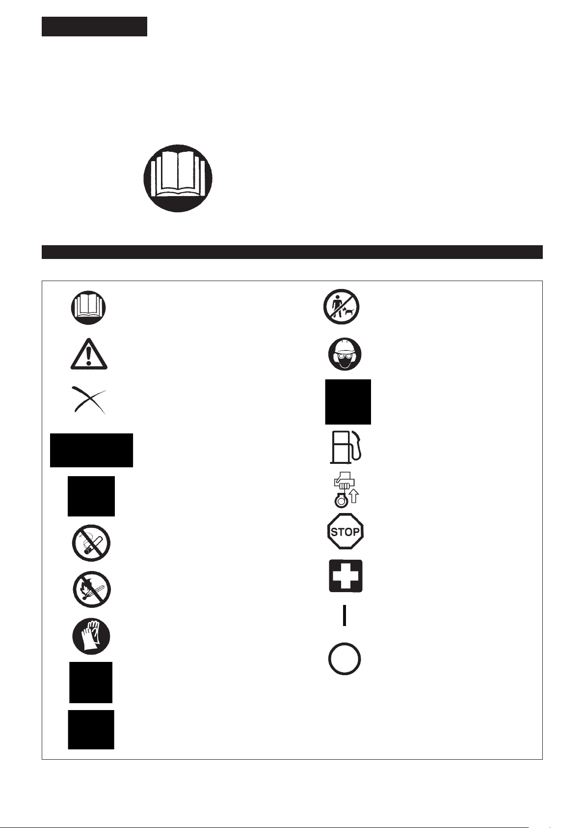
Wear protective helmet, eye and ear
protection!
Top permissible tool speed
Fuel (Gasoline)
Engine-manual start
Emergency stop
First Aid
ON/START
Protective gloves must be worn!
OFF/STOP
Wear sturdy boots with nonslip soles.
Steeltoed safety boots are recommended!
Kickback!
2
Page 3
SAFETY INSTRUCTIONS
General Instructions
Read this instruction manual to become familiar with handling of the –
equipment. Users insufciently informed will risk danger to themselves as
well as others due to improper handling.
It is recommended only to lend the equipment to people who have proven to –
be experienced.
Always hand over the instruction manual.
First users should ask the dealer for basic instructions to familiarize oneself –
with the handling of an engine powered cutter.
Children and young persons aged under 18 years must not be allowed to –
operate this equipment. Persons over the age of 16 years may however
use the device for the purpose of being trained while under supervision of a
qualied trainer.
Use with the utmost care and attention. –
Operate only if you are in good physical condition. Perform all work calmly –
and carefully. The user has to accept liability for others.
Never use this equipment after consumption of alcohol or drugs, or if feeling –
tired or ill.
National regulation can restrict the use of the machine. –
Intended use of the machine
This equipment is only intended for cutting grass, weeds, bushes, –
undergrowth. It should not be used for any other purpose such as edging or
hedge cutting as this may cause injury.
Personal protective equipment
The clothing worn should be functional and appropriate, i.e. it should be tight- –
tting but not cause hindrance. Do not wear either jewelry or clothing which
could become entangled with bushes or shrubs.
In order to avoid either head-, eye-, hand-or foot injuries as well as to protect –
your hearing the following protective equipment and protective clothing must
be used during operation.
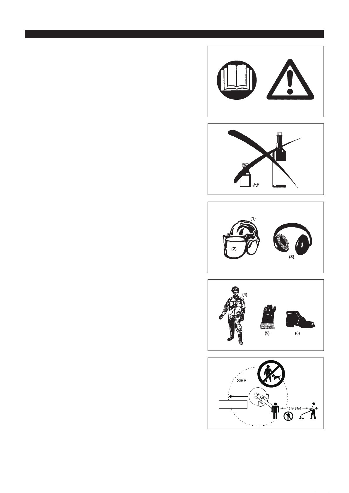
Always wear a helmet where there is a risk of falling objects. The protective –
helmet (1) is to be checked at regular intervals for damage and is to be
replaced at the latest after 5 years. Use only approved protective helmets.
The visor (2) of the helmet (or alternatively goggles) protects the face from –
ying debris and stones. During operation always wear goggles, or a visor to
prevent eye injuries.
Wear adequate noise protection equipment to avoid hearing impairment (ear –
muffs (3), ear plugs etc.).
The work overalls (4) protect against ying stones and debris. –
We strongly recommend that the user wears work overalls.
Gloves (5) are part of the prescribed equipment and must always be worn –
during operation.
When using the equipment, always wear sturdy shoes (6) with a non-slip –
sole. This protects against injuries and ensures a good footing.
Starting up the Brushcutter & String Trimmer
Please make sure that there are no children or other people within a working –
range of 15 meters (50 ft), also pay attention to any animals in the working
vicinity.
Before use always check the equipment is safe for operation: –
Check the security of the cutting tool, the throttle lever for easy action and
check for proper functioning of the throttle lever lock.
Rotation of the cutting tool during idling speed is not allowed. Check with your –
dealer for adjustment if in doubt. Check for clean and dry handles and test
the function of the start/stop switch.
Diagrammatic gure
15 Meters
3
Page 4
Start the Brushcutter or String Trimmer only in accordance with the instructions.
Do not use any other methods for starting the engine! –
Use the Brushcutter/String Trimmer and the tools only for such applications –
as specied.
Only start the engine, after the entire assembly is done. Operation of the –
device is only permitted after all the appropriate accessories are attached!
Before starting make sure that the cutting tool has no contact with hard –
objects such as branches, stones etc. as the cutting tool will revolve when
starting.
The engine is to be switched off immediately in case of any engine problems. –
Should the cutting tool hit stones or other hard objects, immediately switch off –
the engine and inspect the cutting tool.
Inspect the cutting tool at short regular intervals for damage (detection of –
hairline cracks by means of tapping-noise test).
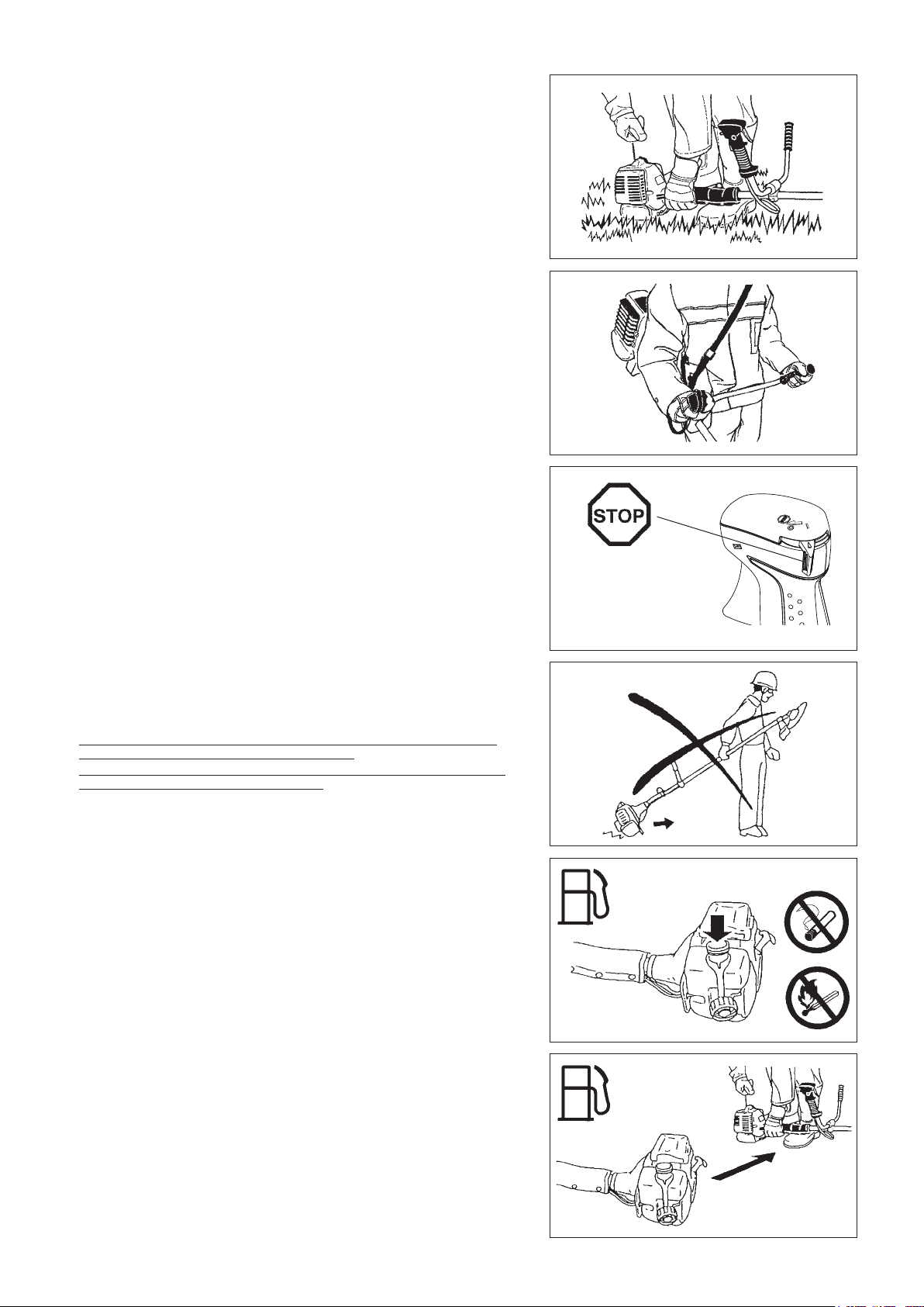
Operate the equipment only with the shoulder strap attached which is to –
be suitably adjusted before putting the Brushcutter or String Trimmer into
operation. It is essential to adjust the shoulder strap according to the user
size to prevent fatigue occurring during use. Never hold the cutter with one
hand during use.
During operation always hold the Brushcutter or String Trimmer with both –
hands.
Always ensure a safe footing.
Operate the equipment in such a manner as to avoid inhalation of the exhaust –
gases. Never run the engine in enclosed rooms (risk of gas poisoning).
Carbon monoxide is an odorless gas.
Switch off the engine when resting and when leaving the equipment –
unattended, and place it in a safe location to prevent danger to others or
damage to the machine.
Never put the hot Brushcutter or String Trimmer onto dry grass or onto any –
combustible materials.
The cutting tool has to be equipped with it appropriate guard. –
Never run the cutter without this guard!
All protective installations and guards supplied with the machine must be –
used during operation.
Never operate the engine with faulty exhaust mufer. –
Shut off the engine during transport. –
During transport over long distances the tool protection included with the –
equipment must always be used.
Ensure safe position of the equipment during car transportation to avoid fuel –
leakage.
When transporting, ensure that the fuel tank is completely empty. –
When unloading the equipment from the truck, never drop the Engine to the –
ground or this may severely damage the fuel tank.
Except in case of emergency, never drop or cast the equipment to the ground –
or this may severely damage the equipment.
Remember to lift the entire equipment from the ground when moving the –
equipment. Dragging the fuel tank is highly dangerous and will cause damage
and leakage of fuel, possibly causing re.
Resting•
Transport•
Refueling•
Maintenance•
Tool replacement•
Refueling
Shut off the engine during refueling, keep away from open ames and do not –
smoke.
Avoid skin contact with mineral oil products. Do not inhale fuel vapor. Always –
wear protective gloves during refueling. Change and clean protective clothing
at regular intervals.
Take care not to spill either fuel or oil in order to prevent soil contamination –
(environmental protection). Clean the brushcutter or string trimmer
immediately after fuel has been spilt.
Avoid any fuel contact with your clothing. Change your clothing instantly if –
fuel has been spilt on it (to prevent clothing catching re).
Inspect the fuel cap at regular intervals making sure that it can be securely –
fastened and does not leak.
Carefully tighten the fuel tank cap. Change location to start the engine (at –
least 3 meters away from the place of refueling).
Never refuel in closed rooms. Fuel vapors accumulate at ground lever (risk of –
explosions).
Only transport and store fuel in approved containers. Make sure the fuel –
stored is not accessible to children.
4
3 meters
Page 5
Method of operation
Only use in good light and visibility. During the winter season beware of –
slippery or wet areas, ice and snow (risk of slipping). Always ensure a safe
footing.
Never cut above waist height. –
Never stand on a ladder. –
Never climb up into trees to perform cutting operation. –
Never work on unstable surfaces. –
Remove sand, stones, nails etc. found within the working range. –
Foreign particles may damage the cutting tool and can cause dangerous
kick-backs.
Before commencing cutting, the cutting tool must have reached full working –
speed.
When using metal blades, swing the tool evenly in half-circle from right to left, –
like using a scythe.
Cutting Tools
Use an applicable cutting tool for the job in hand. –
Nylon cutting heads (nylon line) are suitable for trimming lawn grass.
Metal blades are suitable for cutting weeds, high grasses, bushes, shrubs,
underwood, thicket, and the like.
When using metal blades, always use the approved protector, handle (with –
barrier bar) and harness for use of metal blades. Otherwise blade contact
may cause serious injury. See the section “Approved combination of cutting
tool, protector, handle and harness.”
When using metal blades, avoid “kickback” and always prepare for an –
accidental kickback. See the section “Kickback” and “Kickback prevention.”
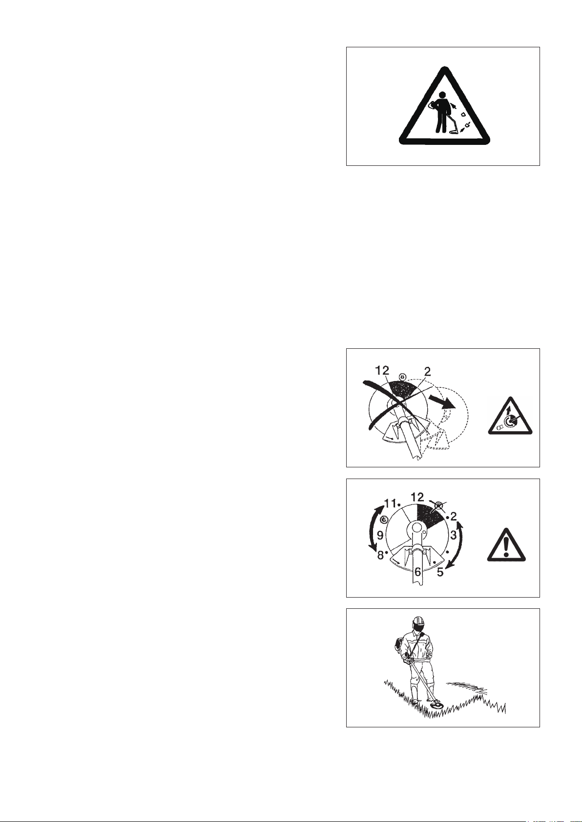
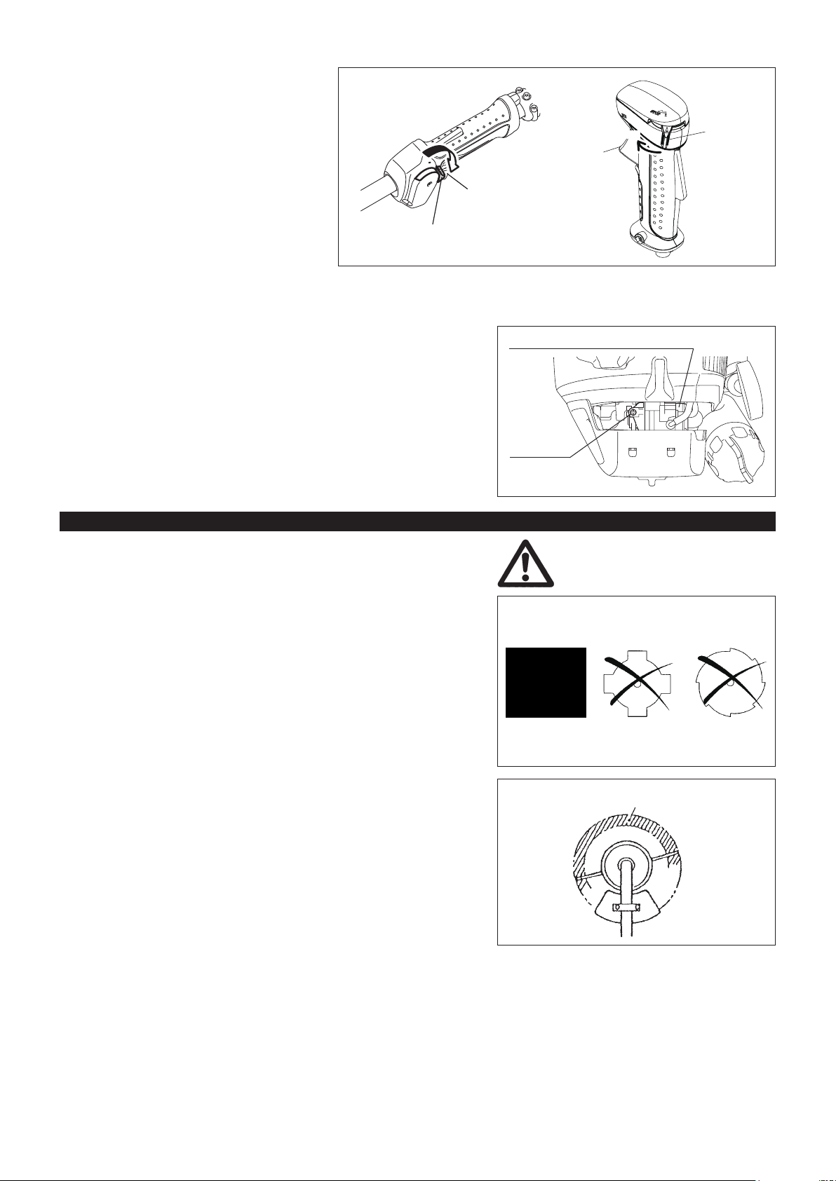
Kickback
When operating the Brushcutter, uncontrolled kickback may occur. –
This is particularly the case when attempting to cut within a blade segment –
between 12 and 2 o’clock.
Never apply the Brushcutter within a segment between 12 and 2 o’clock. –
Never apply this segment of the Brushcutter blade to solids, such as bushes –
and trees, etc., having a diameter in excess of 3 cm or the Brushcutter will be
deected at great force with the risk of injuries.
Kickback prevention
To avoid kickbacks, observe the following:
Operating 12 and 2 o’clock presents a hazard, especially when using metal –
blades.
Cutting 11 and 12 o’clock, and between 2 and 5 o’clock, must be performed –
by trained and experienced operators, and then only at their own risk.
Easy cutting with almost no kickback is possible between 8 and 11 o’clock.
Maintenance instructions
The condition of the cutter, in particular of the cutting tool of the protective –
devices and also of the shoulder strap must be checked before commencing
work. Particular attention is to be paid to the cutting blades which must be
correctly sharpened.
Turn off the engine and remove spark plug connector when replacing or –
sharpening cutting tools, and also when cleaning the cutter or cutting tool.
Caution:
Kickback
Diagrammatic
gure
Diagrammatic
gure
5
Page 6

Never straighten or weld damaged cutting tools.
Pay attention to the environment. Avoid unnecessary throttle operation for –
less pollution and noise emissions. Adjust the carburetor correctly.
Clean the equipment at regular intervals and check that all screws and nuts –
are well tightened.
Never service or store the equipment in the vicinity of naked ames. –
Always store the equipment in locked rooms and with an emptied fuel tank. –
Observe the relevant accident prevention instructions issued by the relevant trade associations and by the insurance companies.
Do not perform any modications to the equipment as this will endanger your safety.
The performance of maintenance or repair work by the user is limited to those activities as described in the instruction manual. All other work is
to be done by an Authorized Service Agent. Use only genuine spare parts and accessories released and supplied by MAKITA.
Use of non-approved accessories and tools means increased risk of accidents.
MAKITA will not accept any liability for accidents or damage caused by the use of non-approved cutting tools and xing devices of cutting tools,
or accessories.
First Aid
In case of accident make sure that a rst-aid box is available in the vicinity of
the cutting operations. Immediately replace any item taken from the rst aid box.
When asking for help, please give the following
information:
Place of accident –
What happened –
Number of injured persons –
Kind of injuries –
Your name –
6
Page 7

TECHNICAL DATA EM2650UH, EM2650LH
Model
Dimensions: length x width x height (without cutting
blade)
Mass (without plastic guard and cutting blade) lbs (kg) 12.11 (5.5) 10.8 (4.9)
Volume (fuel tank) .oz (L) 20.3 (0.6)
Volume (oil tank) .oz (L) 2.7 (0.08)
Engine displacement cu.in (cm
Maximum engine performance hp (kw) 1.1 (0.77) at 7,000 rpm
Engine speed at recommended max. spindle speed RPM (1/min) 10,000
Maximum spindle speed (corresponding) RPM (1/min) 7,400
Idling speed RPM (1/min) 3,000
Clutch engagement speed RPM (1/min) 3,900
Carburetor type WALBRO WYL
Ignition system type Solid state ignition
Spark plug type NGK CMR4A
Electrode gap inch (mm) 0.028” - 0.032” (0.7 - 0.8)
Fuel Automobile gasoline
Engine Oil
Cutting tools (cutter blade dia.) inch (mm) 9 - 1/16” (230) —
Gear ratio 14/19
inch (mm)
69 - 1/2” X 24 - 3/8” X 18 - 2/3”
3
) 1.5 (25.4)
EM2650UH EM2650LH
Bike handle Loop handle
69 - 1/2” X 13 - 3/8” X 13 - 5/8”
(1,765 x 620 x 474)
SAE 10W-30 oil of API Ciassication,
Class SF or higher (4-stroke engine for automobile)
(1,765 x 339 x 347)
7
Page 8
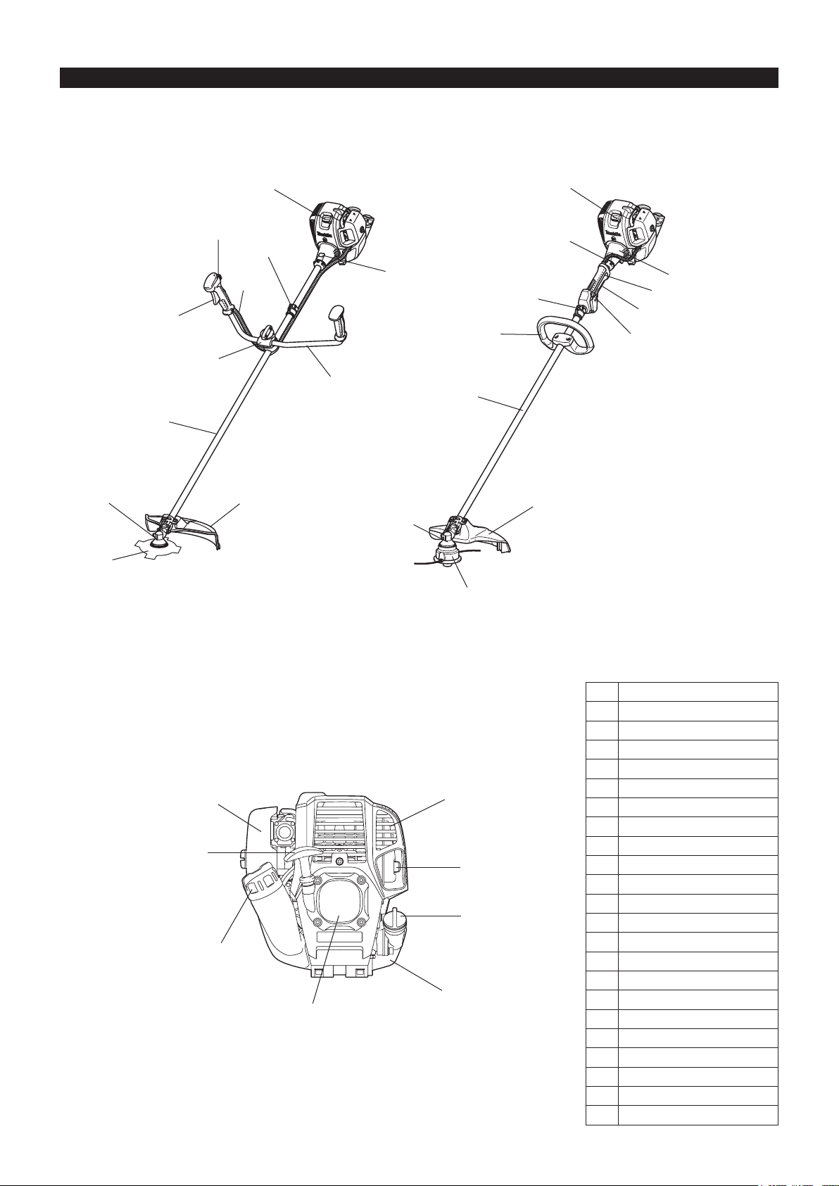
DESIGNATION OF PARTS
5
5
7
9
10
4
12
11
16
15
17
14
13
7
12
4
8
11
9
10
13
15
14
18
EM2650UH
EM2650LH
GB DESIGNATION OF PARTS
1 Fuel tank
2 Rewind starter
3
6
20
21
22
19
1
2
3 Air cleaner
4 I-O switch (on/off)
5 Spark plug
6 Exhaust mufer
7 Clutch case
8 Rear grip
9 Hanger
10 Handle
11 Throttle lever
12 Control cable
13 Shaft
14 Protector
15 Gear Case/Head case
16 Handle holder
17 Cutter blade
18 Nylon cutting head
19 Fuel ller cap
20 Starter knob
21 Exhaust pipe
22 Oil cap
8
Page 9

MOUNTING OF HANDLE
(1)
(2)
(3)
(4)
(5)
CAUTION: Before doing any work on the equipment, always stop the engine
and pull the spark plug connector off the spark plug.
Always wear protective gloves!
CAUTION: Start the engine only after having assembled it completely.
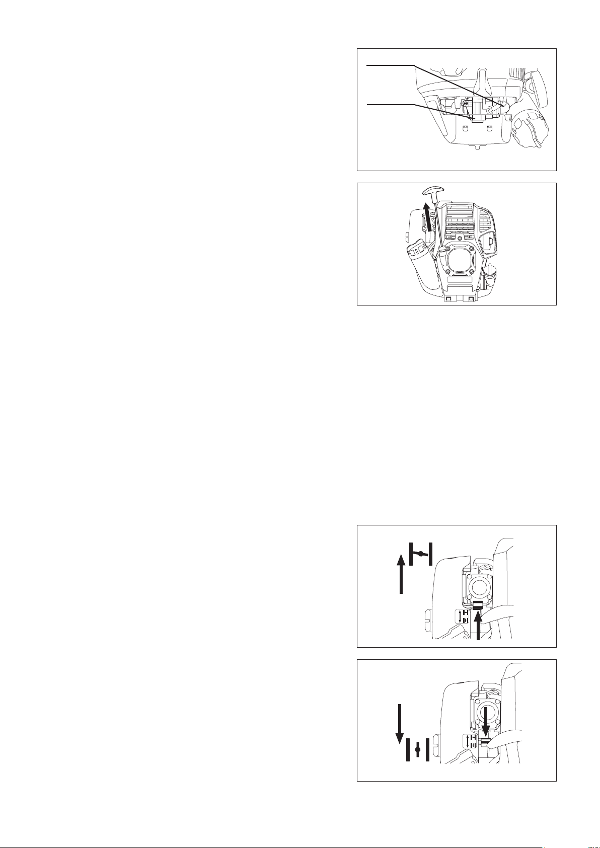
For machines with bike handle models
Loosen knob (1). –
Place handle (4) between handle clamp (2) and handle holder (3). –
Adjust handle (4) to an angle that provides a comfortable working position –
and then secure by rmly hand-tightening knob (1).
CAUTION: Do not forget to mount spring (5).
For machines with loop handle
Fix the loop handle on the shaft as shown. –
To keep a proper distance between the grips, set the loop handle ahead of –
the arrows.
Engine
Engine
9
Page 10
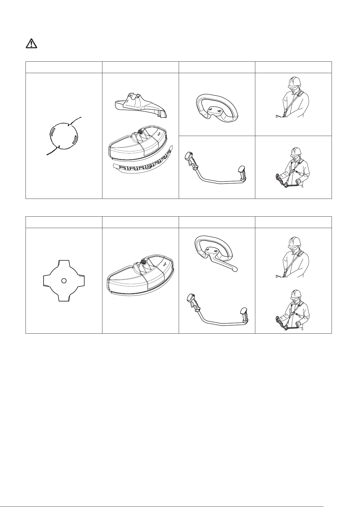
Approved combination of cutting tool, protector, handle and harness
6
7
7
7
8
9
9
10
WARNING: Always use the tool with the approved combination of the safety equipments.
Use of nylon cutting head (EM2650UH, EM2650LH)
Nylon cutting head Protector Handle Harness
Otherwise contact with a cutting tool may cause serious injury.
(With or without barrier bar) (With or without shoulder strap)
(With protector extension)
Use of metal blade (EM2650UH, optional accessory for EM2650LH)
Metal blade Protector Handle Harness
(Without protector extension)
(With barrier bar)
10
Page 11
(1)
(2)
(3)
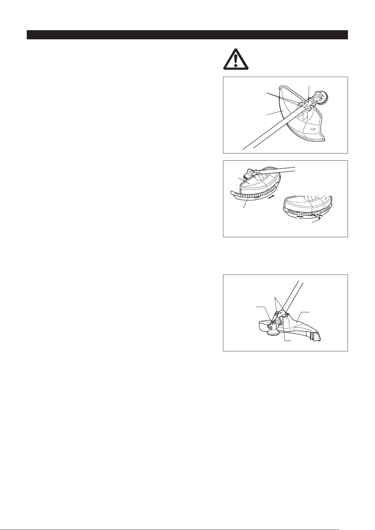
MOUNTING OF PROTECTOR
(3)
(4)
(1)
(2)
(4)
(3)
To meet the applicable safety provisions, only the tool/
protector combinations as indicated in the table must be used.
For EM2650UH
In use of the metal blade, x the protector (3) to the clamp (2) with two bolts –
M6 x 30 (1).
NOTE: Tighten the right and left bolts evenly so that the gap between the clamp
(2) and the protector (3) will be constant.
Otherwise, the protector sometimes may not function as specied.
In cases where the nylon cord cutter is to be used, be sure to mount the –
protector extension (4) onto the metal blade protector (3).
Mount the protector extension (4) by sliding it into place from the ank of the –
metal blade protector (3) as shown.
Remove tape adhered to cutter, which cuts nylon cord, on protector extension –
(4).
CAUTION: Be sure to push in protector extension (4) until it is fully inserted.
Take care not to injure yourself on the cutter for cutting the nylon
cord.
To remove the protector extension (4), apply a hex wrench into the notch on –
the metal blade protector (3), push it in and meanwhile slide the protector
extension (4).
For EM2650LH
Install the clamp (3) on the shaft so that the projection of the clamp (3) is –
inserted into the opening between the gear case (1) and the shaft.
Secure the protector (4) with the installation bolts M6 x 30 (2).
Hex wrench
11
Page 12
(4)
(3)
(2)
(1)
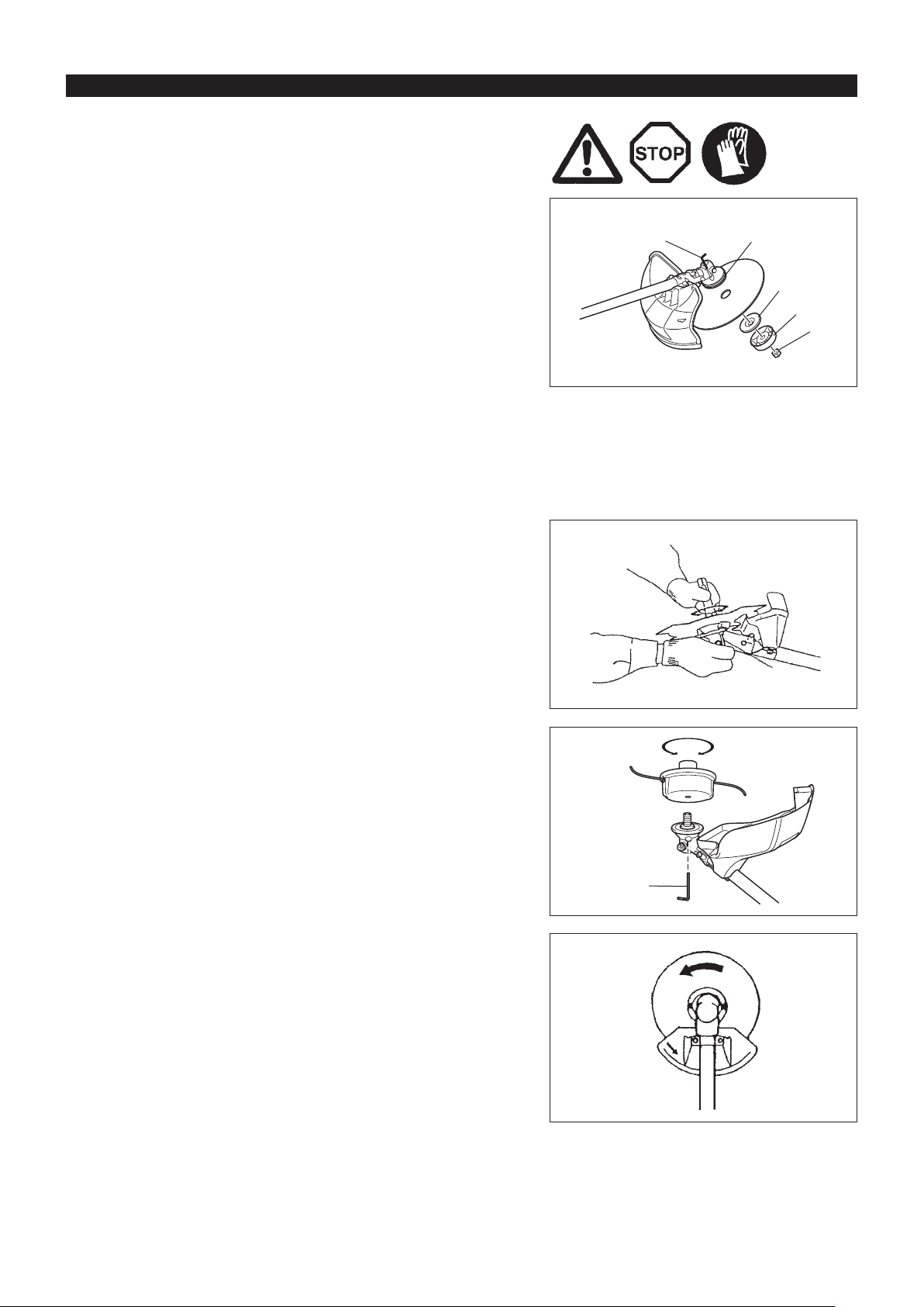
MOUNTING OF CUTTER BLADE OR NYLON CUTTING HEAD
Be sure to use genuine MAKITA cutter blades or nylon
cutting head.
The cutter blade must be well polished, free of cracks or breakage. If the –
cutter blade hits against a stone during operation, stop the engine and check
the blade immediately.
Polish or replace the cutter blade every three hours of operation. –
If the nylon cutting head hits against a stone during operation, stop the –
engine and check the nylon cutting head immediately.
Hex wrench
CAUTION: The appropriate protector must always be installed, for your own
safety and in order to comply with accident-prevention regulations.
Operation of the equipment without the guard being in place is not
permitted.
The outside diameter of the cutter blade must be 230 mm (9 1/16”). Never use any blades surpassing 230 mm (9 - 1/16”) in
outside diameter.
Turn the machine upside down, and you can replace the cutter blade or nylon
cutting head easily.
Insert the hex wrench through the hole in the gear case and rotate the –
receiver washer (4) until it is locked with the hex wrench.
Loosen the nut (1) (left-hand thread) with the socket wrench and remove the –
nut (1), cup (2), and clamp washer (3).
Mounting of cutterblade with the hex wrench still in place
Mount the cutter blade onto the shaft so that the guide of the receiver washer –
(4) ts in the arbor hole in the cutter blade. Install the clamp washer (3), cup
(2), and secure the cutter blade with the nut (1).
[Tightening torque: 13 - 23 N-m]
NOTE: Always wear gloves when handling the cutter blade.
NOTE: The cutter blade-fastening nut (with spring washer) is a consumable
part. If there appears any wear or deformation on the spring washer,
replace the nut.
Mounting of nylon cutting head
The clamp washer (3), cup (2), and nut (1) are not necessary for mounting –
the nylon cutting head. The nylon cutting head should go on top of the
receiver washer (4).
Insert the hex wrench through the hole in the gear case and rotate the –
receiver washer (4) until it is locked with the hex wrench.
Then screw the nylon cutting head onto the shaft by turning it counter- –
clockwise.
Remove the hex wrench. –
Hex wrench
Loosen Tighten
Hex wrench
Rotation
12
Page 13
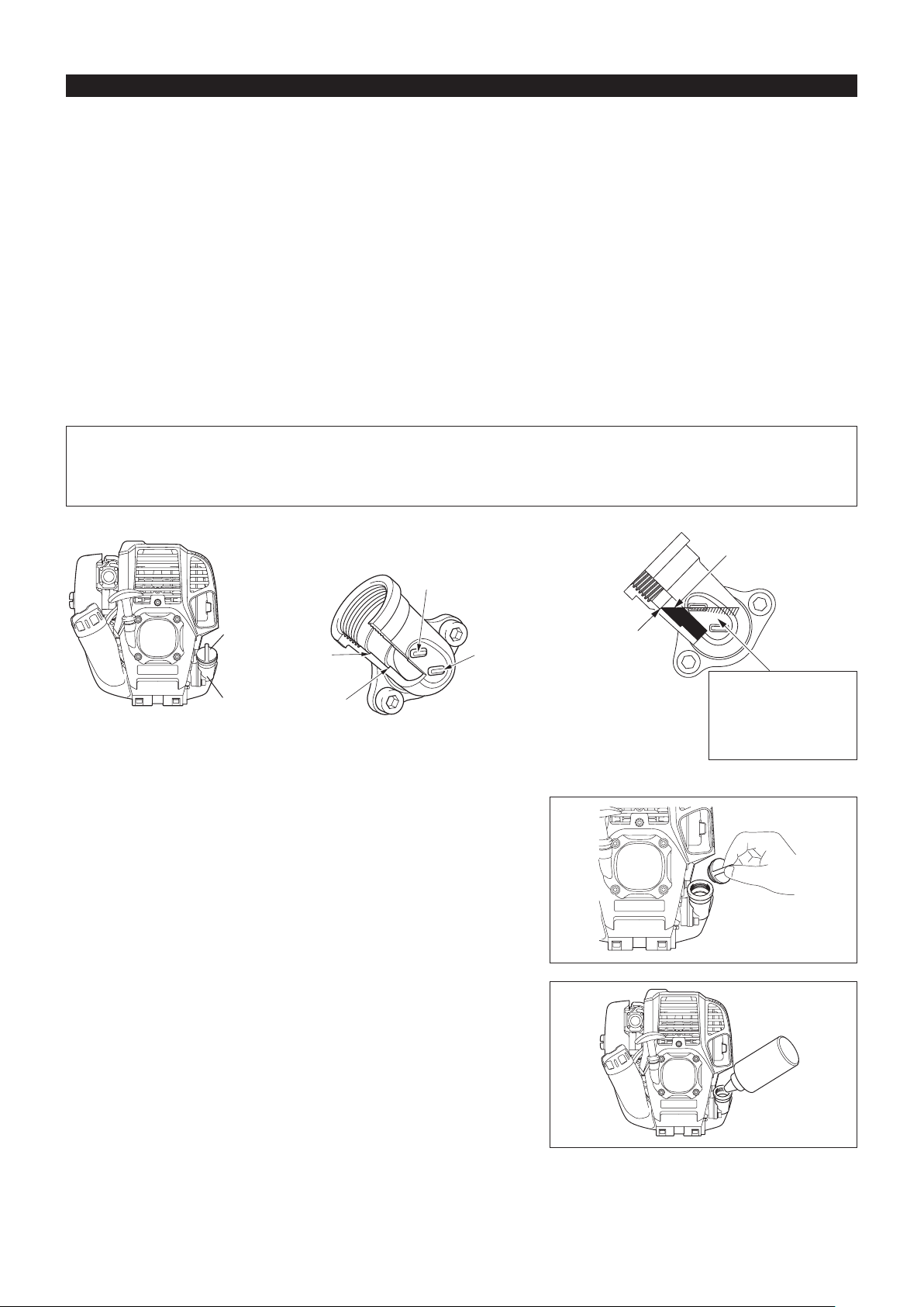
BEFORE START OF OPERATION
Inspectionandrellofengineoil
Perform the following procedure, with the engine cooled down. –
Set the engine level, remove oil cap (Fig. 1), and check to see whether or not there is oil in the range between the upper limit and lower limit –
marks of the oil pipe (Fig. 2).
Fill with oil to upper limit mark if oil is insufcient (oil level is close to lower limit mark) (Fig. 3). –
The area surrounding the external marks is transparent, so the amount of oil inside can be checked without having to remove the oil cap. –
However, if oil pipe becomes extremely dirty, visibility may be lost, and oil level will have to be checked against stepped section on inside of
oil pipe.
For reference, the oil rell time is about 10h (10 times or 10 tanks of gas before oil needs to be relled). –
If the oil changes in color or mixes with dirt, replace it with new one. (For the interval and method of replacement, refer to P 19)
Recommended oil: SAE 10W-30 oil of API Classication, Class SF or higher (4-stroke engine for automobile)
Oil volume: Approx. 0.08L
NOTE: If the engine is not kept upright, oil may pool in other parts of the engine. The oil levelgauge may give an incorrect reading for oil level.
Do not ll with oil if engine is not upright. If the oil is lled above the limit, the oil may be contaminated or may catch re with white
smoke.
Point 1 in Replacement of oil: “Oil cap”
Remove dust or dirt near the oil rell port, and detach the oil cap. –
Keep the detached oil cap free of sand or dust. Otherwise, any sand or dust adhering to the oil cap may cause irregular oil circulation or –
wear on the engine parts, which will result in troubles.
Oil cap
Internal stepped
section (upper
limit)
Oil pipe
Fig. 1
(1) Keep the engine level, and detach the oil cap.
(2) Fill with oil to upper limit mark. (see Fig. 3)
Use oil bottle when lling.
Internal stepped
section (lower
limit)
External mark
(upper limit)
External mark
(lower limit)
Fig. 2 Oil pipe Fig. 3
Top up with oil until
oil level reaches
internal stepped
section (upper
limit).
Oil
The area between the
external upper and lower
limits is transparent, so
oil level can be checked
externally against these
marks.
(3) Securely tighten the oil cap. Insufcient tightening may cause oil leakage.
13
Page 14
Note
Do not replace oil with the engine in a tilted position.•
Filling with oil while engine is tilted leads to overlling which causes oil contamination and/or white smoke.•
Point 2 in Replacement of oil: “If oil spills out”
If oil spills out between the fuel tank and engine main unit, the oil is sucked into through the cooling air intake port, which will contaminate –
the engine. Be sure to wipe out spilt oil before start of operation.
REFUELING
Handling of fuel
It is necessary to handle fuel with utmost care. Fuel may contain substances similar to solvents. Refueling must be performed in a sufciently
ventilated room or in the open air. Never inhale fuel vapor, and keep fuel away from you. If you touch fuel repeatedly or for a long time, the
skin becomes dry, which may cause skin disease or allergy. If fuel enters into the eye, clean the eye with fresh water. If your eye remains still
irritated, consult your doctor.
Storage period of fuel
Fuel should be used within a period of 4 weeks, even if it is kept in a special container in a well-ventilated and shaded area.
Otherwise, fuel may deteriorate in one day.
STORAGE OF MACHINE AND REFILL TANK
Keep the machine and tank at a cool place free from direct sunshine. –
Never keep the fuel in a car. –
Fuel
The engine is a four-stroke engine. Be sure to use an unleaded automobile gasoline 87 or higher octane ((R+M)/2). It may contain no more than
10% alcohol (E-10).
Points for fuel
Never use a gasoline mixture which contains engine oil. Otherwise, it will cause excessive carbon accumulation or mechanical troubles. –
Use of deteriorated oil will cause irregular start-up. –
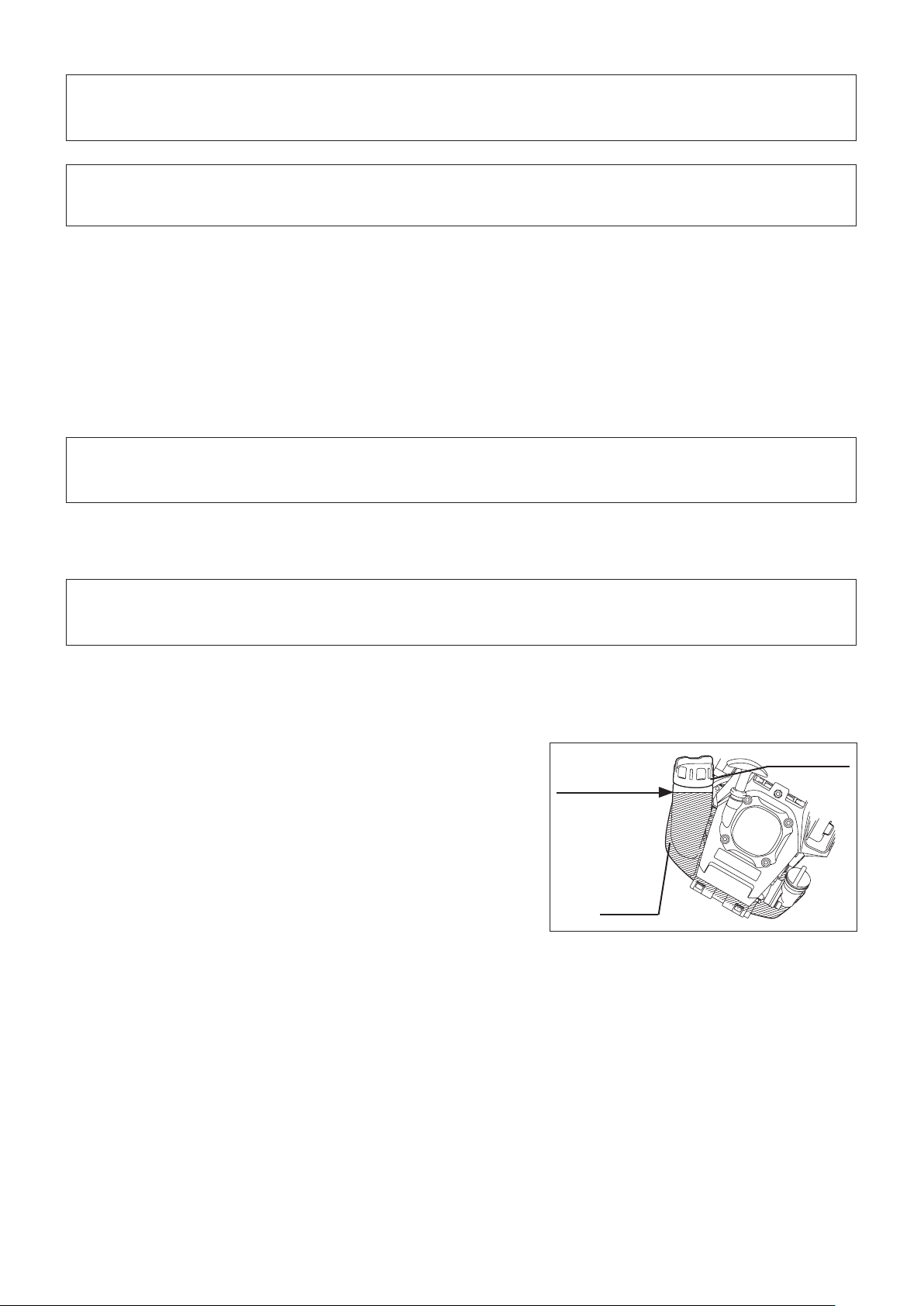
Refueling
WARNING: Shut off the engine before refueling, keep away from
openamesanddonotsmoke.
Gasoline used: Unleaded automobile gasoline, 87 or higher octane. No more
than 10% alcohol (E-10).
Loosen the tank cap a little to release the tank pressure. –
Detach the tank cap, and refuel, discharging air by tilting the fuel tank so that –
the refuel port will be oriented upward. DO NOT ll fuel up to the top of the
tank.
Wipe the outside of the tank cap to prevent debris from entering into the fuel –
tank.
After refueling, securely tighten the tank cap. –
If there is any aw or damage on the tank cap, replace it.•
The tank cap wears out in course of time. Replace it every two to three years.•
DO NOT put fuel in the oil ll port.•
Fuel tank cap
Fuel upper limit
Fuel tank
14
Page 15
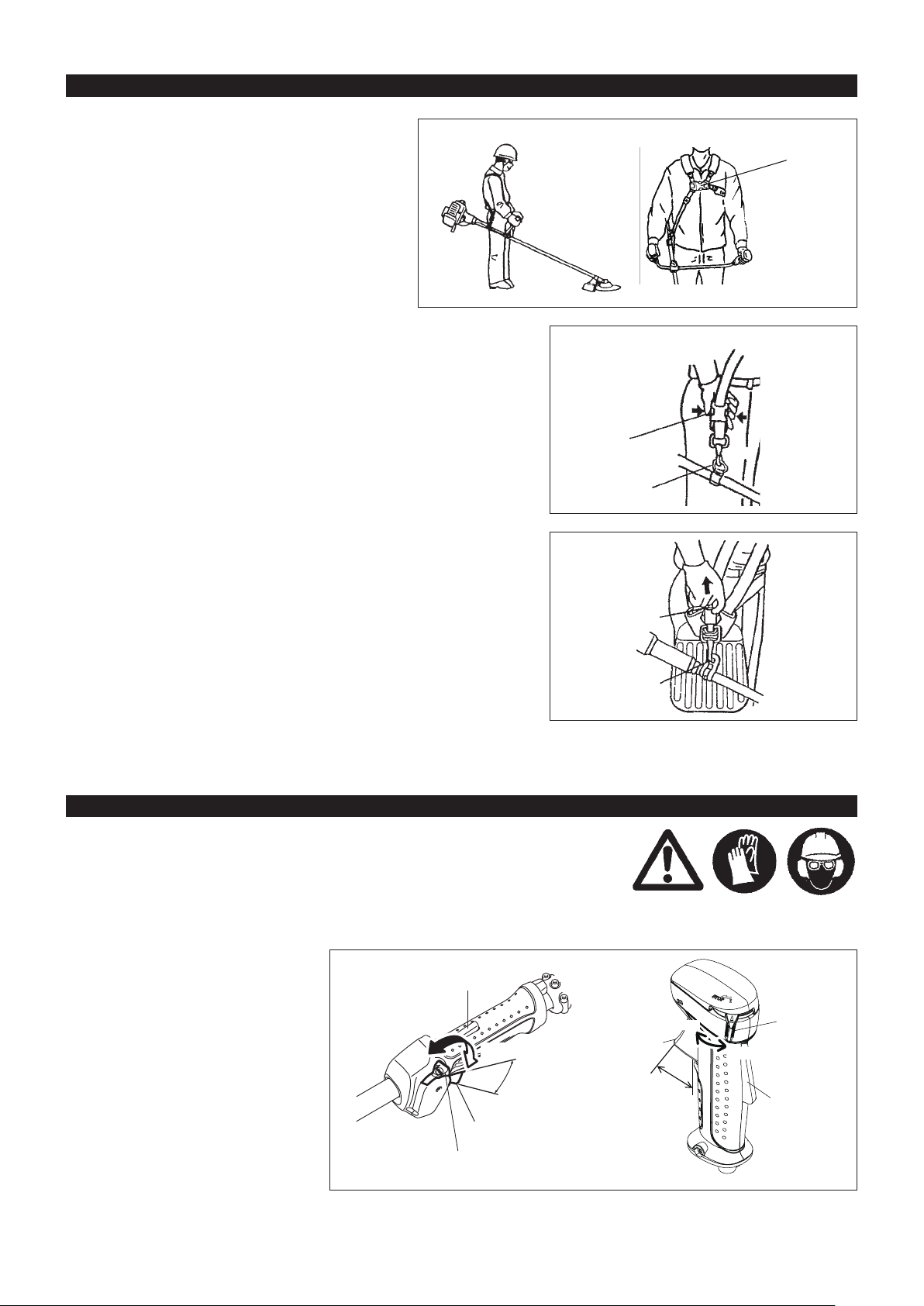
CORRECT HANDLING OF MACHINE
Attachment of shoulder strap
Adjust the strap length so that the cutter blade will be –
kept parallel with the ground.
For EM2650UH
NOTE: Be careful not to trap clothing, etc., in the buckle.
Detachment
For EM2650LH (Optional accessory)
In an emergency, push the notches (1) at both sides, and you can detach the –
machine from you.
Be extremely careful to maintain control of the machine at this time. Do not
allow the machine to be deected toward you or anyone in the work vicinity.
WARNING: Failure to maintain complete control of the machine at all could
result in serious bodily injury or DEATH.
Buckle
EM2650UH
(1)
Hanger
For EM2650UH
In case of emergency, remove the emergency detachment lever (2) by pulling –
strongly with a nger. The machine sill detach from body.
Be extremely careful to maintain control of the machine at this time. Do not
allow the machine to be deected toward you or anyone in the work vicinity.
WARNING: Failure to maintain complete control of the machine at all could
result in serious bodily injury or DEATH.
(2)
Hanger
POINTS IN OPERATION AND HOW TO STOP
Observe the applicable accident prevention regulations!
STARTING
Move at least 3 m away from the place of refueling. Place the unit on the ground taking care that the cutting tool does not come into contact with
the ground or any other objects.
A: Cold start
1) Set this machine on a at space.
2) Set the I-O switch (1) to OPERATION.
OPERATION
Lock-off lever
STOP
Throttle lever
High speed
Low speed
Throttle lever
Low speed
High speed
STOP
(1)
OPERATION
Lock-off lever
(1)
15
EM2650LH EM2650UH
Page 16
3) Primer pump
Continue to push the primer pump until fuel enters into the primer pump. (In
general, fuel enters into the primer pump by 7 to 10 pushes.)
If the primer pump is pushed excessively, an excess of gasoline returns to
the fuel tank.
4) Recoil starter
Pull the start knob gently until it is hard to pull (compression point). Then,
return the start knob, and pull it strongly.
Never pull the rope to the full. Once the start knob is pulled, never release
your hand immediately. Hold the start knob until it returns to its original
point.
5) Warm-up operation
Continue warm-up operation for 2 to 3 minutes.
NOTE:
In case of excessive fuel intake (ooding), remove the spark plug and pull the starter handle slowly to remove excess fuel. Also, dry the •
electrode section of the spark plug.
When operating the tool with a metal blade, don’t open the throttle fully. Operating the tool with the appropriate engine speed for use of metal •
blades (around 6,000 to 8,500 rpm) will save the fuel.
On the other hand, nylon cutting heads requires full throttle for clean cut.
Primer Pump
Carburetor
B: Startup after warm-up operation
1) Push the primer pump repeatedly.
2) Keep the throttle lever at the idling position.
3) Pull the recoil starter strongly.
4) If it is difcult to start the engine, open the throttle by about 1/3.
Pay attention to the cutter blade which may rotate.
At times, such as winter, when starting the engine
is difcult
Operate choke lever with the following procedure when starting engine.
After implementing startup steps 1) to 3), set choke lever to the CLOSE •
position.
Implement startup step 4) and start engine.•
Once engine starts, set choke lever to the OPEN position.•
Implement startup step 5) and complete warm up.•
CAUTION: If a bang (explosive sound) is heard and the engine stops, or the
just-started engine stalls before the choke lever is operated, return
the choke lever to the OPEN position, and pull the starter knob a
few times again to start the engine.
CAUTION: If the choke lever is left in the CLOSE position, and the starter knob
merely pulled repeatedly, too much fuel will be sucked in, and the
engine will become difcult to start.
CLOSE
16
OPEN
Page 17
STOPPING
1) Release the throttle lever (2) fully, and when the
engine rpm has lowered, set the I-O switch to
STOP the engine will now stop.
2) Be aware that the cutting head may not stop
immediately and allow it to slow down fully.
STOP
(2)
(1)
EM2650LH EM2650UH
ADJUSTMENT OF LOW-SPEED ROTATION (IDLING)
When it is necessary to adjust the low-speed rotation (idling), perform it by the carburetor adjusting screw.
(2)
STOP
(1)
CHECKUP OF LOW-SPEED ROTATION
Set the low-speed rotation to 3,000 min –
If it is necessary to change the low speed rotation (idle) speed, use a phillips
head screw driver on the screw illustrated on the right.
Turn the adjusting screw to the right, and the engine rotation will increase. –
Turn the adjusting screw to the left, and the engine rotation will drop.
The carburetor is generally adjusted before shipment. After several tanks of –
gasoline the idle rpm may need to be readjusted.
-1
.
RESHARPENING THE CUTTING TOOL
CAUTION: The cutting tools shown in the illustration are not to be sharpened.
NOTE: To increase the service life of the cutter blade it may be turned over
Manual resharpening will result in imbalances of the cutting tool
causing vibrations and damage to the equipment.
once, until both cutting edges have become blunt.
Carburetor
Adjusting
screw
NYLON CUTTING HEAD
The grass trimmer cutting head is a dual line trimmer head that has bump &
feed mechanism.
The nylon cutting head will feed out the proper length of nylon line after tapping
the trimmer head on the ground by changes in centrifugal force caused by
increasing or decreasing rpms.
Operation
Increase the nylon cutting head speed to approx. 6,000 min –
Bump the trimmer head lightly on the ground.
The most effective cutting area is shown by the shaded area. –
If the nylon cord does not feed out, rewind/replace the nylon cord by following –
the procedures described under “Replacing the nylon cord.”
-1
.
17
Most effective cutting area
Page 18
100 mm
80 mm
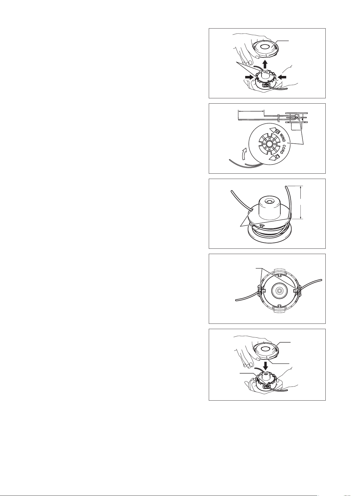
Replacing the nylon cord
WARNING: Make sure that the cover of the nylon cutting head is secured
to the housing properly as described below. Failure to properly
secure the cover may cause the nylon cutting head to y apart
resulting in serious personal injury.
Press inward on the housing latches and lift upward to remove the cover.
Discard any of the remaining nylon cord.
Hook the middle of the new nylon cord to the notch located at the center of the
spool between the 2 channels provided for the nylon cord. One side of the cord
should be about 80 mm longer than the other side.
Wind both ends rmly around the spool in the direction marked on the head for
left hand direction indicated by LH.
Latches
Press
Cover
Press
Wind all but about 100 mm of the cords, leaving the ends temporarily hooked
through a notch on the side of the spool.
Mount the spool in the housing so that the grooves and protrusions on the
spool match up with those in the housing. Keep the side with letters on the
spool visible on the top. Now, unhook the ends of the cord from their temporary
position and feed the cords through the eyelets to come out of the housing.
For left hand
rotation
Notches
Spool
Eyelets
Align the protrusion on the underside of the cover with the slots of the eyelets.
Then push cover rmly onto the housing to secure it. Make sure the latches fully
spread in the cover.
Cover
Protrusion
(Not shown)
Slot of
eyelet
18
Page 19
SERVICING INSTRUCTIONS
CAUTION: Before doing any work on the equipment, always stop the engine and pull the plug cap off the spark plug (see “checking the spark
To ensure a long service life and to avoid any damage to the equipment, the following servicing operations should be performed at regular
intervals.
plug”).
Always wear protective gloves!
Daily checkup and maintenance
Before operation, check the machine for loose screws or missing parts. Pay particular attention to the tightness of the cutter blade or nylon –
cutting head.
Before operation, always check for clogging of the cooling air passage and the cylinder ns. –
Clean them if necessary.
Perform the following work daily after use: –
Clean the equipment externally and inspect for damage.•
Clean the air lter. When working under extremely dusty conditions, clean the lter the several times a day.•
Check the blade or the nylon cutting head for damage and make sure it is rmly mounted.•
Check that there is sufcient difference between idling and engagement speed to ensure that the cutting tool is at a standstill while the •
engine is idling (if necessary reduce idling speed).
If under idling conditions the tool should still continue to run, consult your nearest Authorized Service Agent.
Check the functioning of the I-O switch, the lock-off lever, the throttle lever, and the lock button. –
REPLACEMENT OF ENGINE OIL
Deteriorated engine oil will shorten the life of the engine. Be sure to check the oil and level regularly.
ATTENTION: In general, the engine main unit and engine oil still remain hot just after the engine is stopped. In replacement of oil,
make sure that the engine main unit and engine oil are sufciently cooled down. Otherwise, there may remain a risk
of scald.
NOTE:Iftheoillledabovethelimit,itmaybecontaminatedormaycatchrewithwhitesmoke.
Interval of replacement: After rst 20 operating hours, followed by every 50 operating hours.
Recommended oil: SAE10W-30 oil of API Classication SF Class or higher (4-stroke engine oil for automobile)
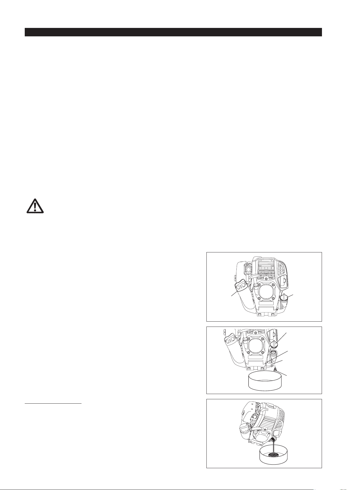
In replacement, perform the following procedure.
1) Make sure that the fuel tank cap is tightened securely.
2) Place large container (pan, etc.) under drain hole.
Fuel tank cap
3) Remove drain bolt and then remove oil cap to drain out oil from drain hole.
At this time, be sure not to lose drain bolt’s gasket, or get dirty any of the
removed components.
4) Once all the oil has been drained, install gasket and drain bolt, and tightly
secure drain bolt, so that it will not loosen and cause leaks.
* Use cloth to fully wipe off any oil attached to bolt and equipment.
Oil cap
Oil cap
Drain hole
Gasket
Drain bolt
Alternative draining method
Remove oil cap, tilt the equipment toward oil ller hole, and drain out oil.
Collect oil in container.
19
Page 20
5) Set the engine level, and gradually ll up to upper limit mark with new oil.
6) After lling, tightly secure oil cap, so that it will not loosen and cause leaks.
If oil cap is not tightly secured, it may leak.
Internal stepped
section (upper
limit)
Internal stepped
section (lower
limit)
Upper limit mark
POINTS ON OIL
Never discard replaced engine oil in garbage, earth or sewage ditch. Disposal of oil is regulated by law. In disposal, always follow the –
relevant laws and regulations. For any points remaining unknown, contact Authorized Service Agent.
Oil will deteriorate even when it is kept unused. Perform inspection and replacement at regular intervals (replace with new oil every –
6 months).
External mark
(upper limit)
External mark
(lower limit)
Oil
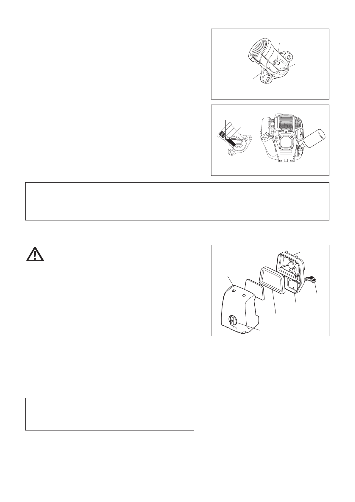
CLEANING OF AIR CLEANER
WARNING: Shutofftheengine,keepawayfromopenames
and do not smoke.
Interval of Cleaning and Inspection: Daily (every 10 operating hours)
Turn the choke lever to the full close side, and keep the carburetor off from –
dust or dirt.
Loosen xing bolt. –
Pull the cover and detach the air cleaner cover. –
If oil adheres to the element (sponge), squeeze it rmly. –
For heavy contamination: –
1) Remove the element (sponge), immerse it in warm water or in waterdiluted neutral detergent, and dry it completely.
2) Clean the element (felt) with gasoline, and dry it completely.
Before attaching the element, be sure to dry it completely. Insufcient drying –
of the element may lead to difcult start-up.
Fit the element (sponge) into the element (felt). –
Fit the elements into the plate so that the sponge faces the air cleaner cover.
Wipe out with waste cloth, oil adhering around the air cleaner cover and plate –
breather part.
Immediately after cleaning is nished, attach the cleaner cover and tighten it –
with xing bolts. (In remounting, rst place the upper hook, and then the lower
hook.)
Points in Handling Air Cleaner Element
Clean the element several times a day, if excessive dust adheres to it. –
If operation continues with the element remaining not cleared of oil, oil in –
the air cleaner may fall outside, resulting in oil contamination.
Plate
Element (sponge)
Air cleaner
cover
Choke
lever
Breather Part
Element (felt)
Fixing bolt
20
Page 21
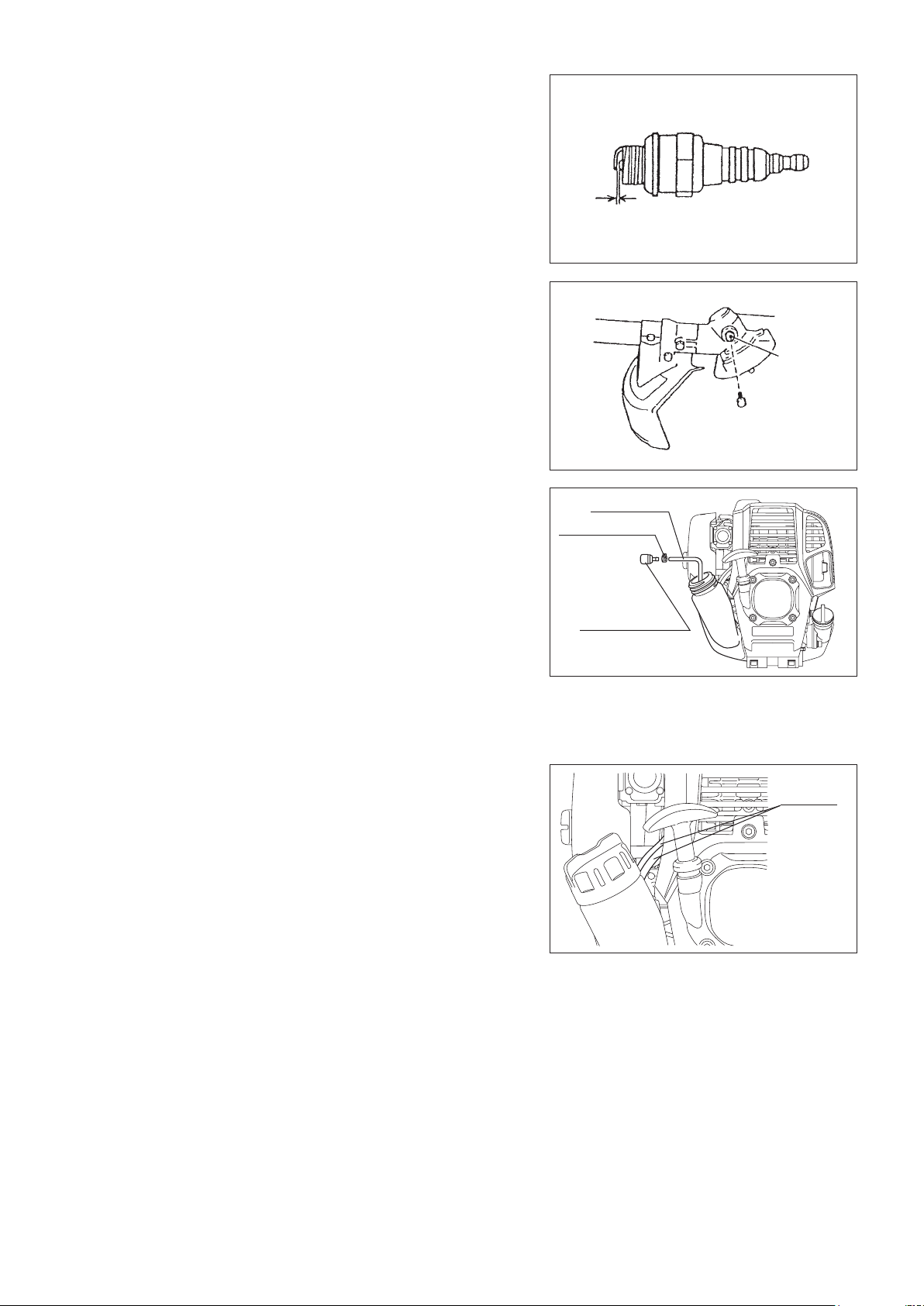
CHECKING THE SPARK PLUG
Only use the supplied universal wrench to remove or to install the spark plug. –
The gap between the two electrodes of the spark plug should be 0.7 - 0.8 mm –
(0.028” - 0.032”). If the gap is too wide or too narrow, adjust it. If the spark
plug is clogged or contaminated, clean it thoroughly or replace it.
CAUTION: Never touch the spark plug connector while the engine is running
(danger of high voltage electric shock).
SUPPLY OF GREASE TO GEAR CASE
Supply grease (Shell Alvania 2 or equivalent) to the gear case through the –
grease hole every 30 hours. (Genuine MAKITA grease may be purchased
from your MAKITA dealer.)
CLEANING OF FUEL FILTER
WARNING: INFLAMMABLES STRICTLY PROHIBITED
Interval of Cleaning and Inspection: Monthly (every 50 operating hours)
Suction head in the fuel tank
The fuel lter (1) of the suction head is used to lter the fuel required by the –
carburetor.
A periodical visual inspection of the fuel lter is to be conducted. Open the –
tank cap, use a wire hook and pull out the suction head through the tank
opening. If the lter is hard or clogged up, replace it.
Replace the fuel lter at least quarterly to ensure an enough fuel supply to the –
carburetor. Otherwise an insufcient fuel supply will cause the engine start
failure and limited maximum speed.
0.7 mm - 0.8 mm
(0.028” - 0.032”)
Gear case
Grease hole
Fuel pipe
Hose clamp
Fuel lter (1)
REPLACEMENT OF FUEL PIPE
CAUTION: INFLAMMABLES STRICTLY PROHIBITED
Interval of Cleaning and Inspection: Daily (every 10 operating hours)
Replacement: Annually (every 200 operating hours)
Replace the fuel pipe every year, regardless of operating frequency. Fuel
leakage may lead to re.
If any leakage is detected during inspection, replace the fuel pipe immediately.
Fuel pipe
INSPECTION OF BOLTS, NUTS AND SCREWS
Retighten loose bolts, nuts, etc. –
Check the fuel cap and oil cap for tightness. Check for fuel and oil leakage. –
Replace damaged parts with new ones for safety operation. –
CLEANING OF PARTS
Always keep the engine clean. –
Keep the cylinder ns free of dust or dirt. Dust or dirt adhering to the ns will –
cause piston seizure.
REPLACEMENT OF GASKETS AND PACKINGS
In reassembling the engine, be sure to replace the gaskets and packings with new ones.
Any maintenance or adjustment work that is not included and described in this manual is only to be performed by Authorized Service Agents.
21
Page 22
STORAGE
WARNING: When draining the fuel, be sure to stop the engine and make sure that the engine
cools down.
Just after stopping the engine, it may still be hot with possibility of burns,
inammabilityandre.
ATTENTION: When the machine is kept out of operation for a long time, drain up all fuel from the
fuel tank and carburetor, and keep it at a dry and clean place.
Drain fuel from the fuel tank and carburetor according to the following –
procedure:
1) Remove the fuel tank cap, and drain fuel completely.
If there is any foreign matter remaining in the fuel tank, remove it
completely.
2) Pull out the fuel lter from the rell port using a wire.
3) Push the primer pump until fuel is drained from there, and drain fuel
coming into the fuel tank.
4) Put the lter to the fuel tank, and securely tighten the fuel tank cap.
5) Then, continue to operate the engine until it stops.
Remove the spark plug, and drip several drops of engine oil through the –
spark plug hole.
Gently pull the starter handle so that engine oil will spread over the engine, –
and attach the spark plug.
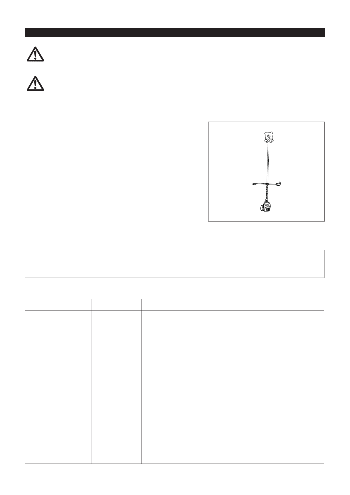
Attach the cover to the cutter blade. –
During storage, keep the rod horizontal or keep the machine upright with the –
blade edge oriented upward. (In this case, pay full attention to prevent the
machine from falling.)
Never store the machine with the cutter blade edge oriented downward.
Lubricating oil may spill out.
Keep the drained fuel in a special container in a well-ventilated shade. –
Attention after long-time storage
Before startup after long-time shutdown, be sure to replace oil (refer to P 19). Oil will deteriorate while the machine is kept out of –
operation.
Fault location
Fault System Observation Cause
Engine not starting or with
difculty
Warm start problems Tank lled ignition spark
Engine starts but dies Fuel supply Tank lled Incorrect idling adjustment, carburetor contaminated
Ignition system Ignition spark O.K. Fault in fuel supply or compression system, mechanical
defect
No ignition spark STOP-switch operated, wiring fault or short circuit, spark
plug or connector defective, ignition module faulty
Fuel supply Fuel tank lled Incorrect choke position, carburetor defective, fuel supply
line bent or blocked, fuel dirty
Compression No compression when
pulled over
Mechanical fault Starter not engaging Broken starter spring, broken parts inside of the engine
existing
Cylinder bottom gasket defective, crankshaft seals
damaged, cylinder or piston rings defective or improper
sealing of spark plug
Carburetor contaminated, have it cleaned
Fuel tank vent defective, fuel supply line interrupted,
cable or STOP-switch faulty
Insufcient performance Several systems may
simultaneously be
affected
Engine idling poor Air lter contaminated, carburetor contaminated, mufer
clogged, exhaust duct in the cylinder clogged
22
Page 23

Item
Operating time
Before
operation
After
lubrication
Daily
(10h)
30h 50h 200h
Shutdown/
rest
Corres-
ponding P
Engine oil
Inspect/clean
Replace
Tightening parts
(bolt, nut)
Inspect
Clean/inspect
Fuel tank
Drain fuel
Throttle lever Check function
Stop switch Check function
Cutting blade Inspect
Low-speed rotation Inspect/adjust
Air cleaner Clean
Ignition plug Inspect
Cooling air duct Clean/inspect
Inspect
Fuel pipe
Replace
Gear-case grease Rell
13
1
*
19
21
—
3
*
22
—
17
11
17
20
21
21
21
2
*
—
21
Fuel lter Clean/replace
Clearance between air intake
valve and air discharge valve
Adjust
Engine overhaul
Carburetor Drain fuel
*1 Perform initial replacement after 20h operation.
*2 For the 200 operating hour inspection, request Authorized Service Agent or a machine shop.
*3 After emptying the fuel tank, continue to run the engine and drain fuel in the carburetor.
21
2
*
2
*
3
*
—
—
22
23
Page 24

TROUBLESHOOTING
Before making a request for repairs, check for trouble by yourself. If any abnormality is found, control your machine according to the description
of this manual. Never tamper or dismount any part contrary to the description. For repairs, contact Authorized Service Agent or local dealership.
State of abnormality Probable cause (malfunction) Remedy
Failure to operate primer pump Push 7 to 10 times
Low pulling speed of starter rope Pull strongly
Lack of fuel Feed fuel
Clogged fuel lter Clean
Broken fuel tube Straighten fuel tube
Deteriorated fuel Deteriorated fuel makes starting more difcult.
Replace with new fuel. (Recommended
replacement: 1 month)
Excessive suction of fuel Set throttle lever from medium speed to high
speed, and pull starter handle until engine
starts. Once engine starts, cutter blade
Engine does not start
Engine stops soon
Engine speed does not increase
Cutter blade does not rotate
Stop engine immediately
Main unit vibrates abnormally
Stop engine immediately
Cutter blade does not stop immediately
Stop engine immediately
Engine does not stop
Run engine at idling, and set choke lever
to CLOSE
Detached plug cap Attach securely
Contaminated spark plug Clean
Abnormal clearance of spark plug Adjust clearance
Other abnormality of spark plug Replace
Abnormal carburetor Make request for inspection and maintenance.
Starter rope cannot be pulled Make request for inspection and maintenance.
Abnormal drive system Make request for inspection and maintenance.
Insufcient warm-up Perform warm-up operation
Choke lever is set to “CLOSE” although
engine is warmed up.
Clogged fuel lter Clean
Contaminated or clogged air cleaner Clean
Abnormal carburetor Make request for inspection and maintenance.
Abnormal drive system Make request for inspection and maintenance.
Loosened cutter blade-tightening nut Tighten securely
Twigs caught by cutter blade or dispersion-
preventing cover.
Abnormal drive system Make request for inspection and maintenance.
Broken, bent or worn cutter blade Replace cutter blade
Loosened cutter blade-tightening nut Tighten securely
Shifted convex part of cutter blade and cutter
blade support tting.
Abnormal drive system Make request for inspection and maintenance.
High idling rotation Adjust
Detached throttle wire Attach securely
Abnormal drive system Make request for inspection and maintenance.
Detached connector Attach securely
Abnormal electric system Make request for inspection and maintenance.
starts rotating. Pay full attention to cutter
blade.
If engine will not start still, remove spark plug,
dry the electrode, and reassemble them as
they originally are. Then, start as specied.
Set to “OPEN”
Remove foreign matter
Attach securely
When the engine does not start after warm-up operation:
If there is no abnormality found for the check items, open the throttle by about 1/3 and start the engine.
24
Page 25

EMISSION COMPLIANCE PERIOD
For handheld engine: The Emissions
Compliance Period referred to on the Emissions
Compliance label indicates the number of operating hours for which the engine has been shown to meet Federal emission
requirements.
Category C=50 hours, B=125 hours, and A=300 hours.
AIR INDEX
An Air Index Information hang tag was supplied to this engine in accordance with the emission regulations of the California Air
Resources Board.
The bar graph on the hang tag shows the emissions performance of this engine.
The bar graph can be used to compare the emissions performance with other available engine.
The lower the Air Index, the less pollution.
The following durability description is to provide you with information relating to the emission durability period of the engine.
Descriptive Term Applicable to Emissions Durability Period
Moderate – 50 hours (0-65 cc)
Intermediate – 125 hours (0-65 cc)
Extended – 300 hours (0-65 cc)
Notice: The Air Index Information hang tag must remain on the engine or on the equipment until it is sold to the ultimate
purchaser. Remove the hang tag before operating the engine.
25
Page 26

CALIFORNIA EMISSIONS CONTROL WARRANTY STATEMENT
YOUR WARRANTY RIGHTS AND OBLIGATIONS
The California Air Resources Board and Makita USA, Inc are pleased to explain the emissions control system’s warranty on your 2007 and
later small off-road engine. In California, new equipment that use small off-engines must be designed, built, and equipped to meet the State’s
stringent anti-smog standards. Makita USA, Inc must warrant the emissions control system on your small off-road engine for the period listed
below provided there has been no abuse, neglect or improper maintenance of your equipment.
Your emissions control system may include parts such as: carburetors or fuel injection system, ignition system, catalytic converters, fuel tanks,
valves, lters, clamps, connectors, and other associated components. Also, included may be hoses, belts, connectors, sensors, and other
emission-related assemblies.
Where a warrantable condition exists, Makita USA, Inc will repair your small off-road engine at no cost to you including diagnosis, parts and
labor.
MANUFACTURER’S WARRANTY COVERAGE:
This emissions control system is warranted for two years. If any emissions-related part on your equipment is defective, the part will be repaired
or replaced by Makita USA, Inc.
OWNER’S WARRANTY RESPONSIBILITIES:
As the small off-road engine owner, you are responsible for performance of the required maintenance listed in your owner’s manual. • Makita
USA, Inc recommends that you retain all receipts covering maintenance on your small off-road engine, but Makita USA, Inc cannot deny
warranty solely for the lack of receipts or your failure to ensure the performance of all scheduled maintenance.
As the small off-road engine owner, you should however be aware that • Makita USA, Inc may deny you warranty coverage if your small off-
road engine or a part has failed due to abuse, neglect, or improper maintenance or unapproved modications.
You are responsible for presenting your small off-road engine to a • Makita Factory Service Center as soon as the problem exists. The
warranty repairs should be completed in a reasonable amount of time, not to exceed 30 days. If you have a question regarding your warranty
coverage, you should contact:
* For the nearest Makita service center, please visit www.makitatools.com
* For technical support or questions regarding operation of our tools and accessories call: 1-800-4-MAKITA
*MakitaUSAInc.CorporateOfce:14930NorthamSt.LaMirada,CA90638-5753
DEFECTS WARRANTY REQUIREMENTS:
(a) The warranty period begins on the date the engine or equipment is delivered to an ultimate purchaser.
(b) General Emissions Warranty Coverage. Makita USA, Inc must warrant to the ultimate purchaser and each subsequent owner that the engine
or equipment is:
(1) Designed, built, and equipped so as to conform with all applicable regulations adopted by the Air Resources Board; and
(2) Free from defects in materials and workmanship that causes the failure of a warranted part for a period of two years.
(c) The warranty on emissions-related parts will be interpreted as follows:
(1) Any warranted part that is not scheduled for replacement as required maintenance in the written instructions required by subsection (d)
must be warranted for the warranty period dened in Subsection (b) (2). If any such part fails during the period of warranty coverage,
it must be repaired or replaced by the manufacturer according to Subsection (4) below. Any such part repaired or replaced under the
warranty must be warranted for the remaining warranty period.
(2) Any warranted part that is scheduled only for regular inspection in the written instructions required by subsection (d) must be
warranted for the warranty period dened in Subsection (b) (2). A statement in such written instructions to the effect of “repair or
replace as necessary” will not reduce the period of warranty coverage. Any such part repaired or replaced under warranty must be
warranted for the remaining warranty period.
(3) Any warranted part that is scheduled for replacement as required maintenance in the written instructions required by subsection
(d) must be warranted for the period of time prior to the rst scheduled replacement point for that part. If the part fails prior to the
rst scheduled replacement, the part must be repaired or replaced by the engine manufacturer according to Subsection (4) below.
Any such part repaired or replaced under warranty must be warranted for the remainder of the period prior to the rst scheduled
replacement point for the part.
(4) Repair or replacement of any warranted part under the warranty must be performed at no charge to the owner at a warranty station.
(5) Notwithstanding the provisions of Subsection (4) above, warranty services or repairs must be provided at all manufacturer distribution
centers that are franchised to service the subject engines.
(6) The owner must not be charged for diagnostic labor that leads to the determination that a warranted part is in fact defective, provided
that such diagnostic work is performed at a warranty station.
(7) The manufacturer is liable for damages to other engine components proximately caused by a failure under warranty of any warranted
part.
(8) Throughout the emissions warranty period dened in Subsection (b) (2), the manufacturer must maintain a supply of warranted parts
sufcient to meet the expected demand for such parts.
(9) Any replacement part may be used in the performance of any warranty maintenance or repairs and must be provided without charge to
the owner. Such use will not reduce the warranty obligations of the manufacturer.
(10) Add-on or modied parts that are not exempted by the Air Resources Board may not be used. The use of any non-exempted add on
or modied parts will be grounds for disallowing a warranty claim. The manufacturer will not be liable to warrant failures of warranted
parts caused by the use of a non-exempted add-on or modied part.
(11) The manufacturer issuing the warranty shall provide any documents that describe that manufacturer’s warranty procedures or policies
(d) Emission Warranty Parts List.
within ve working days of request by the Air Resources Board.
(1) Fuel Metering System
(i) Carburetor and internal parts
(ii) Fuel Filter
(iii) Fuel Tank.
26
Page 27

(2) Air Induction System
(i) Air cleaner plate (including choke system)
(ii) Air cleaner cover
(iii) Air cleaner element
(3) Ignition System
(i) Spark Plugs.
(ii) Magneto or electronic ignition system.
(iii) Spark advance/retard system.
(4) Miscellaneous Items Used in Above Systems
(i) Hoses, Sealing gaskets, belts, connectors, and assemblies.
Makita USA, Inc will furnish with each new engine written instructions for the maintenance and use of the engine by the owner.
(e) MAINTENANCE STATEMENTS
It is your responsibility to have all scheduled inspection and maintenance services performed at the times recommended in the 2007 and
later Owner’s Manual and to retain proof that inspection and maintenance services are performed at the times when recommended. Makita
USA, Inc will not deny a warranty claim solely because you have no record of maintenance; however, Makita USA, Inc may deny a warranty
claim if your failure to perform required maintenance resulted in the failure of warranted part. The proof, which you maintain, should be given
to each subsequent owner of the engine. You are responsible for performing the scheduled maintenance described below based on the
procedures specied in the 2007 and later Owner’s Manual. The scheduled maintenance below is based on the normal engine-operating
schedule.
PROCEDURE INTERVAL
1) Clean engine and check bolts and nuts. Retighten if
: Every 8 hours (daily)
necessary.
2) Check and rell engine oil (4 stroke engine only) : Every 8 hours (rell daily up to upper limit)
3) Change engine oil (4 stroke engine only) : Initial 20 hours and every 50 hours afterward
4) Check clogging of cooling air passage and cylinder
: Every 8 hours (daily)
ns. Remove and clean if necessary.
5) Clean air cleaner. : Every 8 hours (daily)
6) Check spark plug. Clean and adjust if necessary. : Every 8 hours (daily)
7) Check mufer exhaust outlet (or port). Clean if
: Every 50 hours (monthly)
necessary.
8) Check fuel lter. If clogged, replace with new one. : Every 50 hours (monthly)
9) Adjust valve clearance, if applicable (4 stroke
: Every 200 hours (yearly)
engine only).
10) Replace fuel lines. : Every 200 hours (yearly)
11) Clean and inspect the complete engine. Replace
: Every 200 hours
any damaged or worn out parts.
12) Replace packings and gaskets with new ones. : Every reassembling
27
Page 28

FEDERAL EMISSION COMPONENT DEFECT WARRANTY
EMISSION COMPONENT DEFECT WARRANTY COVERAGE - This emission warranty is applicable in all States,
except the State of California
Makita U.S.A., Inc., (herein “Makita”) warrant to the initial retail purchaser and each subsequent owner, that this
utility equipment engine (herein “engine”) was designed, built, and equipped to conform at the time of initial sale to
all applicable regulations of the U.S. Environmental Protection Agency (EPA), and that the engine is free of defects
in materials and workmanship which would cause this engine to fall to conform with EPA regulations during its
warranty period.
For the components listed under PARTS COVERED, the dealer or service center authorized by Makita will, at no
cost to you, make the necessary diagnosis, repair, or replacement necessary to ensure that the engine complies
with applicable U.S. EPA regulations.
EMISSION COMPONENT DEFECT WARRANTY PERIOD
The warranty period for this engine begins on the date of sale to the initial purchaser and continues for a period of
2 years.
PARTS COVERED
Listed below are the parts covered by the Emission Component Defect Warranty. Some of the parts listed below
may require scheduled maintenance and are warranted up to the rst scheduled replacement point for that part.
1) Fuel Metering System
(i) Carburetor and internal parts
(ii) Fuel lter, if applicable
(iii) Throttle stopper, if applicable
(iv) Choke System, if applicable
2) Air Induction System
(i) Air cleaner plate
(ii) Air cleaner case
(iii) Air cleaner element
3) Ignition System
(i) Spark plug
(ii) Flywheel Magneto
(iii) Ignition Coil
4) Miscellaneous Items Used in Above Systems
(i) Fuel hoses, clamps and sealing gaskets
28
Page 29

OBTAINING WARRANTY SERVICE
To obtain warranty service, take your engine to the nearest MAKITA Factory Service Center authorized by
MAKITA. Bring your sales receipts indicating date of purchase for this engine. The dealer or service center
authorized by Makita will perform the necessary repairs or adjustments within a reasonable amount of time and
furnish you with a copy of the repair order. All parts and accessories replaced under this warranty become the
property of Makita.
WHAT IS NOT COVERED
* Conditions resulting from tampering, misuse, improper adjustment (unless they were made by the dealer
or service center authorized by Makita during a warranty repair), alteration, accident, failure to use the
recommended fuel and oil, or not performing required maintenance services.
* The replacement parts used for required maintenance services.
* Consequential damages such as loss of time, inconvenience, loss of use of the engine of equipment, etc.
* Diagnosis and inspection charges that do not result in warranty-eligible service being performed.
* Any non-authorized replacement part, or malfunction of authorized parts due to use of non-authorized parts.
OWNER’S WARRANTY RESPONSIBILITIES
As the engine owner, you are responsible for the performance of the required maintenance listed in your owner’s
manual, Makita recommends that you retain all receipts covering maintenance on your engine, but Makita can
not deny warranty solely for the lack of receipts or for your failure to ensure the performance of all scheduled
maintenance.
As the engine owner, you should however be aware that the Makita may deny your warranty coverage if your
engine or a part has failed due to abuse, neglect, improper maintenance or unapproved modications.
You are responsible for presenting your engine to the nearest dealer or service center authorized by Makita when a
problem exists.
If you have any questions regarding your warranty rights and responsibilities, you should contact the Followings:
* For the nearest Makita service center, please visit www.makitatools.com
* For technical support or questions regarding operation of our tools and accessories call: 1-800-4-MAKITA
* Makita USA Inc. Corporate Ofce: 14930 Northam St. La Mirada, CA 90638-5753
(For Canada)
* For the authorized service center nearest you please refer to the local yellow pages directory under “tools”, or
contact our customer service department Tel 1-800-263-3734 (Canada only), or visit our web site www.makita.ca
* Makita Canada Inc. Head Ofce & Plant: 1950 Forbes Street, Whitby, ON L1N7B7.
29
Page 30

THINGS YOU SHOULD KNOW ABOUT THE EMISSION CONTROL SYSTEM WARRANTY
MAINTENANCE AND REPAIRS
You are responsible for the proper use and maintenance of the engine. You should keep all receipts and
maintenance records covering the performance of regular maintenance in the event questions arise. These receipts
and maintenance records should be transferred to each subsequent owner of the engine. Makita reserves the
rights to deny warranty coverage if the engine has not been properly maintained. Warranty claims will not be
denied, however, solely because of the lack of required maintenance or failure to keep maintenance records.
MAINTENANCE, REPLACEMENT OR REPAIR OF EMISSION CONTROL DEVICES AND
SYSTEMS MAY BE PERFORMED BY ANY REPAIR ESTABLISHMENT OR INDIVIDUAL;
HOWEVER, WARRANTY REPAIRS MUST BE PERFORMED BY A DEALER OR SERVICE
CENTER AUTHORIZED BY Makita. THE USE OF PARTS THAT ARE NOT EQUIVALENT
IN PERFORMANCE AND DURABILITY TO AUTHORIZED PARTS MAY IMPAIR THE
EFFECTIVENESS OF THE EMISSION CONTROL SYSTEM AND MAY HAVE A BEARING ON
THE OUTCOME OF A WARRANTY CLAIM.
If other than the parts authorized by Makita are used for maintenance replacements or for the repair of components
affecting emission control, you should assure yourself that such parts are warranted by their manufacturer to be
equivalent to the parts authorized by Makita in their performance and durability.
HOW TO MAKE A CLAIM
All repairs qualifying under this limited warranty must be performed by a service dealer authorized by MAKITA.
In the event that any emission-related part is found to be defective during the warranty period, you shall notify
MAKITA at the following contacts and you will be advised of the appropriate warranty service dealer or
service providers where the warranty repair can be performed.
* For the nearest Makita service center, please visit www.makitatools.com
* For technical support or questions regarding operation of our tools and accessories call: 1-800-4-MAKITA
* Makita USA Inc. Corporate Ofce: 14930 Northam St. La Mirada, CA 90638-5753
(For Canada)
* For the authorized service center nearest you please refer to the local yellow pages directory under “tools”, or
contact our customer service department Tel 1-800-263-3734 (Canada only), or visit our web site www.makita.ca
* Makita Canada Inc. Head Ofce & Plant: 1950 Forbes Street, Whitby, ON L1N7B7.
30
Page 31

Français
(Mode d’emploi original)
Merci d’avoir acheté l’équipement de jardinage motorisé MAKITA. Nous
sommes heureux de vous recommander ce produit MAKITA qui est le fruit
d’un long programme de développement et de nombreuses années de
connaissances et d’expérience.
Veuillez lire ce document, il décrit en détail les performances remarquables de
cette machine. Il vous aidera à obtenir les meilleurs résultats possibles de votre
produit MAKITA.
PICTOGRAMMES
Vous verrez les pictogrammes suivants en lisant le manuel d’instructions.
Lire le manuel d’instructions et respecter
les avertissements et mesures de
sécurité!
Table des matières Page
Pictogrammes..............................................................31
Consignes de sécurité .................................................32
Données techniques ....................................................36
Désignation des pièces ...............................................37
Montage de la poignée ................................................38
Montage du protecteur ................................................40
Montage de la lame de coupe ou de la tête à ls
nylon ............................................................................41
Avant utilisation ...........................................................42
Manipulation correcte de la machine ...........................44
Remarques concernant le fonctionnement et l’arrêt
de la machine ..............................................................44
Réaffûtage de l’outil de coupe .....................................46
Instructions d’entretien ................................................48
Entreposage ................................................................51
Zone de travail interdite aux individus et
aux animaux!
Faire particulièrement attention!
Interdit!
Ne pas s’approcher!
Danger de projections!
Défense de fumer!
Flamme nue interdite!
Casque de protection, protections oculaire
et auditive obligatoires!
Vitesse d’outil maximale autorisée
Carburant (essence)
Démarrage manuel du moteur
Arrêt d’urgence
Premiers soins
MARCHE/DÉMARRAGE
Gants de protection obligatoires!
ARRÊT/COUPURE MACHINE
Portez des chaussures solides avec
semelle antidérapante.
Il est conseillé de porter des chaussures
avec embout de sécurité!
Mouvement de recul!
31
Page 32

CONSIGNES DE SÉCURITÉ
Consignes générales
Lisez ce manuel d’instructions an de vous familiariser avec le –
fonctionnement de l’équipement. S’ils ne sont pas sufsamment informés, les
utilisateurs qui manipulent la machine de façon incorrecte représentent un
danger pour eux-mêmes comme pour les autres.
Il est recommandé de ne prêter cet équipement qu’à des personnes –
expérimentées.
Fournissez toujours le manuel d’instructions.
Les utilisateurs inexpérimentés doivent demander des instructions de base –
au vendeur an de se familiariser avec la manipulation de la débroussailleuse
motorisée.
N’autorisez pas les enfants et les personnes de moins de 18 ans à utiliser –
cet équipement. Les personnes âgées de plus de 16 ans peuvent toutefois
utiliser la machine en vue d’apprentissage si elles sont toujours sous la
surveillance d’un adulte qualié.
Utilisez la machine avec le maximum de soin et d’attention. –
N’utilisez la machine que si vous êtes en bonne condition physique. –
Manipulez délicatement et soigneusement la machine. L’utilisateur doit
accepter d’assumer la responsabilité pour les autres.
N’utilisez jamais cet équipement après avoir consommé de l’alcool ou de la –
drogue, ou si vous vous sentez fatigué ou malade.
La réglementation nationale peut limiter l’utilisation de cette machine. –
Utilisation normale de la machine
Cet équipement est conçu pour couper de l’herbe, des buissons et des –
broussailles. Il ne doit en aucun cas être utilisé dans un autre but, comme
le dressage de bordures ou la taille de haies. Cela représente un risque de
blessure.
Équipement de protection personnel
La tenue portée doit être fonctionnelle et appropriée, autrement dit elle doit –
être ajustée et ne pas entraver les mouvements. Ne portez pas de bijoux ni
de vêtements qui pourraient s’accrocher dans les buissons ou les arbustes.
An d’éviter les blessures à la tête, aux yeux, aux mains ou aux pieds et –
de protéger votre ouïe, vous devez porter l’équipement et les vêtements de
protection indiqués ci-dessous lorsque vous utilisez l’équipement.
Portez toujours un casque s’il y a un risque de chute d’objets. Le casque de –
protection (1) doit être inspecté fréquemment en vue d’éventuels dommages
et doit être remplacé au moins tous les 5 ans. Utilisez uniquement des
casques de protection homologués.
La visière-écran (2) du casque (ou à défaut les lunettes étanches) protège le –
visage des projections de débris et de pierres. Portez toujours des lunettes
étanches ou une visière lorsque vous utilisez l’équipement, an de prévenir
les blessures aux yeux.
Portez un équipement anti-bruit adéquat an d’éviter une perte auditive –
(protège-oreilles (3), bouchons d’oreilles, etc.).
La combinaison de travail (4) protège contre les projections de débris et de –
pierres.Il est vivement recommandé à l’utilisateur de porter une combinaison
de travail.
Les gants (5) font partie de l’équipement recommandé et doivent toujours –
être portés pendant l’utilisation de la machine.
Lorsque vous utilisez la machine, portez toujours des chaussures renforcées –
(6) dotées de semelles antidérapantes. Cela vous préservera des blessures
et vous assurera une bonne stabilité.
Démarrage de la débroussailleuse thermique
Veillez à éloigner les enfants ou toute autre personne dans un périmètre de –
travail de 15 mètres (50 pieds) et faites également attention aux animaux
présents dans cette zone.
Avant utilisation, vériez toujours que l’équipement est en bon état de –
fonctionnement :
Contrôlez l’état de l’outil de coupe, puis vériez que le levier d’accélérateur
peut être actionné facilement et que la sécurité du levier d’accélérateur
fonctionne correctement.
L’outil de coupe ne doit pas tourner lorsque la machine est au ralenti. –
Vériez le réglage auprès de votre vendeur en cas de doute. Vériez
que les poignées sont propres et sèches, et testez le fonctionnement du
commutateur marche/arrêt.
Schéma de
représentation
15 mètres
32
Page 33

Suivez strictement les instructions pour démarrer la débroussailleuse thermique.
Ne démarrez pas le moteur d’une autre façon. –
N’utilisez la débroussailleuse thermique et ses outils que pour l’utilisation à –
laquelle ils sont destinés.
Ne démarrez le moteur qu’une fois que la machine est totalement montée. Le –
fonctionnement de la machine n’est possible qu’une fois tous les accessoires
correctement xés!
Avant le démarrage, veillez à ce que l’outil de coupe ne soit pas en contact –
avec des objets durs tels que des branches, des pierres, etc., étant donné
qu’il amorcera la rotation au démarrage.
Vous devez couper immédiatement le moteur s’il présente un –
dysfonctionnement.
Si l’outil de coupe heurte des pierres ou des objets durs, coupez –
immédiatement le moteur et inspectez l’outil de coupe.
Inspectez fréquemment l’outil de coupe en vue d’éventuels dommages –
(détection de craquelures grâce à un test de bruit de battement).
Utilisez l’équipement seulement après avoir mis la sangle d’épaule; celle- –
ci doit être réglée adéquatement avant que la débroussailleuse thermique
ne soit mise en marche. La sangle d’épaule doit être ajustée à la taille de
l’utilisateur an d’éviter une fatigue à l’utilisation. Ne saisissez jamais l’outil de
coupe à la main lorsque la machine est en marche.
Lorsque vous utilisez la débroussailleuse thermique, tenez-la toujours avec –
les deux mains.
Assurez-vous toujours de votre stabilité.
Utilisez l’équipement de manière à éviter l’inhalation des gaz d’échappement. –
Ne faites jamais fonctionner le moteur dans une pièce fermée (risque
d’asphyxie au gaz).
Le monoxyde de carbone est un gaz inodore.
Coupez le moteur lorsque vous faites une pause ou que vous laissez –
l’équipement sans surveillance et placez-le dans un endroit sûr an de ne pas
mettre les autres en danger et de ne pas l’endommager.
Ne posez jamais la débroussailleuse thermique chaude sur de l’herbe sèche –
ou sur un matériau combustible.
L’outil de coupe doit être équipé de la gaine prévue à cet effet. –
N’utilisez jamais les ls nylon sans cette gaine.
Toutes les installations de protection et gaines fournies avec la machine –
doivent être utilisées lors de son utilisation.
N’utilisez jamais le moteur si le silencieux d’échappement est défectueux. –
Coupez le moteur pendant le transport. –
Pendant les transports sur de longues distances, la protection d’outil fournie –
avec l’équipement doit toujours être utilisée.
Placez l’équipement dans une position sûre lors de transports en voiture an –
d’éviter toute fuite d’essence.
Lors des transports, assurez-vous que le réservoir d’essence est –
complètement vide.
Lors du déchargement de l’équipement d’un camion, ne laissez jamais tomber –
le moteur par terre, cela pourrait sérieusement endommager le réservoir
d’essence.
Sauf en cas d’urgence, ne faites jamais tomber l’équipement ou ne le lancez –
pas par terre; cela risquerait de provoquer des dommages graves.
Ne traînez pas l’équipement sur le sol lorsque vous le transportez. Il est très –
dangereux de faire traîner le réservoir d’essence, cela pourrait l’endommager,
provoquer une fuite d’essence, voire même déclencher un incendie.
Pause•
Transport•
Remplissage•
Entretien•
Remplacement d’outil•
Remplissage
Coupez le moteur pendant le remplissage du réservoir, éloignez-vous de toute –
amme et ne fumez pas.
Évitez tout contact des produits pétroliers avec la peau. N’inhalez pas les –
vapeurs d’essence. Portez toujours des gants de protection pendant le
remplissage du réservoir. Changez et nettoyez souvent les vêtements de
protection.
Veillez à ne pas renverser l’essence ou l’huile an de ne pas contaminer les –
sols (protection de l’environnement). Nettoyez la débroussailleuse thermique
immédiatement si de l’essence a été renversée.
Évitez les projections d’essence sur vos vêtements. Changez immédiatement –
vos vêtements en cas de projection d’essence (pour éviter qu’ils ne
s’enamment).
Inspectez régulièrement le bouchon du réservoir d’essence pour vous assurer –
qu’il se ferme correctement et qu’il ne fuit pas.
Serrez bien le bouchon du réservoir d’essence. Déplacez-vous pour démarrer –
le moteur (à au moins 3 mètres du lieu de remplissage du réservoir).
Ne remplissez jamais le réservoir dans une pièce fermée. Les vapeurs –
d’essence s’accumulent au ras du sol (risque d’explosions).
Ne transportez et ne conservez l’essence que dans des conteneurs –
appropriés. Veillez à conserver l’essence hors de portée des enfants.
33
3 mètres
Page 34

Mode de fonctionnement
Utilisez l’équipement seulement avec un bon éclairage et dans de bonnes –
conditions de visibilité. En hiver, faites attention aux sols glissants et aux
zones humides, à la glace et à la neige (risque de glissade). Assurez-vous
toujours de votre stabilité.
Ne réalisez jamais de coupe en tenant la machine plus haut que votre taille. –
Ne montez jamais sur une échelle. –
Ne réalisez jamais de coupe en étant perché dans un arbre. –
Ne travaillez pas sur des surfaces instables. –
Retirez le sable, les pierres, les clous, etc. trouvés dans le périmètre de –
travail.
Les corps étrangers peuvent endommager l’outil de coupe et entraîner des
mouvements de recul dangereux.
Avant de commencer la coupe, l’outil de coupe doit avoir atteint sa vitesse –
maximale.
Lorsque vous utilisez des lames métalliques, déplacez l’outil régulièrement –
en demi cercle de droite à gauche, comme si vous utilisiez une faux.
Outils de coupe
Utilisez un outil de coupe approprié pour le travail à effectuer. –
Les têtes à ls nylon (ls nylon) conviennent pour couper le gazon.
Les lames métalliques conviennent pour couper les herbes hautes, les
buissons, les arbustes, les broussailles, les fourrés, etc.
Lorsque vous utilisez des lames métalliques, utilisez toujours le protecteur, –
la poignée (avec barre de protection) et la sangle homologués et prévus à
cet effet. Si vous ne le faites pas, un contact avec la lame peut entraîner des
blessures graves. Consultez la section « Ensemble outil de coupe, protecteur,
poignée et sangle homologué ».
Lorsque vous utilisez des lames métalliques, évitez les « mouvements –
de recul » et préparez-vous au cas où il s’en produirait un de manière
accidentelle. Consultez la section « Mouvement de recul » et « Prévention
des mouvements de recul ».
Mouvement de recul
Lorsque vous utilisez la débroussailleuse thermique, un mouvement de recul –
incontrôlable peut se produire.
Cela arrive notamment lorsque vous essayez de couper avec un segment de –
lame compris entre 12 et 2 heures.
N’appliquez jamais la débroussailleuse thermique avec un segment compris –
entre 12 et 2 heures.
N’appliquez jamais ce segment de lame de la débroussailleuse thermique sur –
des corps solides, tels que des buissons, des arbres, etc., ayant un diamètre
de plus de 3 cm sans quoi la débroussailleuse thermique serait violemment
détournée, et vous risqueriez de vous blesser.
Prévention des mouvements de recul
And’éviterlesmouvementsderecul,observezlesconsignes
suivantes :
Utiliser un segment compris entre 12 et 2 heures représente un danger, en –
particulier si vous utilisez des lames métalliques;
Les coupes en appliquant les segments entre 11 et 12 h et 2 et 5 h doivent –
être réalisées par des utilisateurs formés et expérimentés, à leurs risques et
périls.
Une coupe aisée presque sans aucun mouvement de recul est possible en
appliquant le segment entre 8 et 11 h.
Consignes d’entretien
Vous devez vérier l’état de l’outil de coupe, des protections et de la sangle –
d’épaule, avant de commencer à travailler. Prêtez particulièrement attention
aux lames de coupe qui doivent être correctement affûtées.
Coupez le moteur et retirez le connecteur de la bougie d’allumage lorsque –
vous remplacez ou affûtez les outils de coupe, et également lorsque vous les
nettoyez.
Attention :
Mouvement de recul
Schéma
dereprésentation
Schéma
dereprésentation
34
Page 35

Ne réparez ni ne soudez jamais des outils de coupe
endommagés.
Pensez à protéger l’environnement. Évitez d’utiliser l’accélérateur de –
manière excessive pour réduire les émissions de gaz et de bruit. Réglez le
carburateur correctement.
Nettoyez l’équipement à intervalles réguliers et vériez que toutes les vis et –
tous les écrous sont bien serrés.
Ne réparez ou n’entreposez jamais l’équipement à proximité de ammes –
nues.
Entreposez toujours l’équipement dans une pièce fermée à clé avec le –
réservoir d’essence vide.
Respectez les consignes de prévention des accidents fournies par les associations professionnelles ainsi que par les compagnies d’assurance
concernées.
N’apportez aucune modication à l’équipement, cela vous mettrait en danger.
L’entretien ou les réparations réalisables par l’utilisateur sont ceux décrits dans le manuel d’instructions. Tout autre travail doit être réalisé par un
technicien agréé. N’utilisez que des pièces de rechange et accessoires fabriqués et vendus par MAKITA.
L’utilisation d’accessoires et outils non agréés accroît le risque d’accidents.
MAKITA décline toute responsabilité en cas d’accidents ou de dommages du fait de l’utilisation d’outils de coupe, de dispositifs de xation
d’outils de coupe ou d’accessoires non agréés.
Premiers soins
En cas d’accident, veillez à avoir une trousse de premiers soins non loin de
la zone de travail. Remplacez sans délai tout article utilisé dans la trousse de
premiers soins.
Si vous demandez de l’aide, veillez à donner les
informations suivantes :
lieu de l’accident; –
conditions de l’accident; –
nombre de personnes blessées; –
le type de blessure; –
votre nom. –
35
Page 36

DONNÉES TECHNIQUES EM2650UH, EM2650LH
Modèle
Dimensions : longueur x largeur x hauteur (hors
lame de coupe)
Poids (hors gaine plastique et lame de coupe) lb (kg) 12,11 (5,5) 10,8 (4,9)
Volume (réservoir d’essence) oz liq (l) 20,3 (0,6)
Volume (réservoir d’huile) oz liq (l) 2,7 (0,08)
Cylindrée
Rendement maximal du moteur hp (kW) 1,1 (0,77) à 7 000 tr/min
Vitesse moteur à la vitesse de broche maximale
recommandée
Vitesse de broche maximale (correspondante) TR/MIN (1/min) 7 400
Vitesse au ralenti TR/MIN (1/min) 3 000
Vitesse d’embrayage TR/MIN (1/min) 3 900
Carburateur type WALBRO WYL
Système d’allumage type Allumage transistorisé
Bougie d’allumage type NGK CMR4A
Distance entre les électrodes pouce (mm) 0,028” - 0,032” (0,7 - 0,8)
Carburant Essence automobile
Huile moteur
Outils de coupe (diamètre de la lame de coupe) pouce (mm) 9 - 1/16” (230) —
Rapport de transmission 14/19
pouce (mm)
pouce cube
(cm
TR/MIN (1/min) 10 000
69 - 1/2” X 24 - 3/8” X 18 - 2/3”
3
)
EM2650UH EM2650LH
Guidon Poignée arceau
69 - 1/2” X 13 - 3/8” X 13 - 5/8”
(1 765 x 620 x 474)
1,5 (25,4)
SAE 10W-30 huile de classication API,
classe SF ou supérieure (moteur automobile à 4 temps)
(1 765 x 339 x 347)
36
Page 37

DÉSIGNATION DES PIÈCES
5
5
7
9
10
4
12
11
16
15
17
14
13
7
12
4
8
11
9
10
13
15
14
18
EM2650UH
EM2650LH
F DÉSIGNATION DES PIÈCES
1 Réservoir d’essence
2 Démarreur à rappel
3
6
20
21
22
19
1
2
3 Filtre à air
4 Commutateur (marche/arrêt)
5 Bougie d’allumage
6 Silencieux d’échappement
7 Carter d’embrayage
8 Poignée arrière
9 Étrier de xation
10 Poignée
11 Levier d’accélérateur
12 Câble de commande
13 Axe
14 Protecteur
15 Carter d’engrenage/Carter de la tête
16 Support de la poignée
17 Lame de coupe
18 Tête à ls nylon
19 Bouchon du réservoir d’essence
20 Poignée de démarrage
21 Tuyau d’échappement
22 Bouchon d’huile
37
Page 38

MONTAGE DE LA POIGNÉE
(1)
(2)
(3)
(4)
(5)
ATTENTION : Avant d’effectuer tout travail sur l’équipement, coupez toujours le
moteur et retirez le connecteur de la bougie d’allumage.
Portez toujours des gants de protection.
ATTENTION : Ne démarrez le moteur qu’après l’avoir entièrement assemblé.
Pour les machines avec guidon
Desserrez la molette (1). –
Placez le guidon (4) entre la pièce de serrage (2) et le support (3). –
Réglez le guidon (4) à un angle qui permet une position de travail confortable –
et xez-le solidement en serrant la molette (1) à la main.
ATTENTION : N’oubliez pas de monter le ressort (5).
Pour les machines avec poignée arceau
Fixez la poignée arceau sur l’axe comme indiqué. –
Pour conserver une distance correcte entre les poignées, placez la poignée –
arceau devant les èches.
Moteur
Moteur
38
Page 39

Ensemble outil de coupe, protecteur, poignée et sangle homologué
6
7
7
7
8
9
9
10
AVERTISSEMENT : Utilisez toujours l’outil avec l’ensemble d’équipements de sécurité homologué.
Utilisationd’unetêteàlsnylon(EM2650UH,EM2650LH)
Tête à ls nylon Protecteur Poignée Sangle
Si vous ne le faites pas, un contact avec l’outil de coupe peut entraîner des blessures graves.
(avec ou sans barre de
protection) (avec ou sans sangle d’épaule)
(avec extension de protecteur)
Utilisation d’une lame métallique (EM2650UH, accessoire en option pour EM2650LH)
Lame métallique Protecteur Poignée Sangle
(avec barre de protection)
(sans extension de protecteur)
39
Page 40

MONTAGE DU PROTECTEUR
(1)
(2)
(3)
(3)
(4)
(1)
(2)
(4)
(3)
An de respecter les consignes de sécurité en vigueur, vous ne devez utiliser
que les ensembles outil/protecteur indiqués dans le tableau.
Pour le EM2650UH
Si vous utilisez une lame métallique, xez le protecteur (3) à la pièce de –
serrage (2) avec deux boulons M6 x 30 (1).
REMARQUE : Serrez de la même façon les boulons droit et gauche an qu’il y
ait le même écart entre la pièce de serrage (2) et le protecteur
(3).
Sinon le protecteur peut parfois ne pas fonctionner comme
spécié.
Si vous devez utiliser des ls nylon, veillez à monter l’extension de protecteur –
(4) sur le protecteur des lames métalliques (3).
Montez l’extension de protecteur (4) en la faisant glisser à sa place depuis le –
côté du protecteur des lames métalliques (3) comme illustré.
Retirez l’adhésif des ls nylon, sur l’extension de protecteur (4). –
ATTENTION : Veillez à appuyer sur l’extension de protecteur (4) jusqu’à ce
qu’elle soit complètement insérée.
Faites attention à ne pas vous blesser sur la lame servant à
couper les ls nylon.
Pour retirer l’extension de protecteur (4), placez une clé hexagonale dans –
l’entaille sur le protecteur des lames métalliques (3), appuyez dessus tout en
faisant glisser l’extension de protecteur (4).
Pour le EM2650LH
Placez la pièce de serrage (3) sur l’axe de manière à ce que la partie –
saillante de la pièce de serrage (3) soit insérée dans l’ouverture entre le
carter d’engrenage (1) et l’axe.
Fixez le protecteur (4) à l’aide des boulons de xation M6 x 30 (2).
Clé hexagonale
40
Page 41

MONTAGE DE LA LAME DE COUPE OU DE LA TÊTE À FILS NYLON
(4)
(3)
(2)
(1)
Veillezàutiliserdeslamesdecoupeouunetêteàlsnylon
MAKITA.
La lame de coupe doit être correctement polie, et n’être ni craquelée, ni –
brisée. Si la lame de coupe heurte une pierre en cours de fonctionnement,
coupez le moteur et vériez immédiatement l’état de la lame.
Polissez ou remplacez la lame de coupe toutes les trois heures. –
Si la tête à ls nylon heurte une pierre en cours de fonctionnement, coupez le –
moteur et vériez immédiatement l’état de la tête à ls nylon.
Clé hexagonale
ATTENTION : Le protecteur approprié doit toujours être installé, pour
votre propre sécurité, mais également an de répondre à la
réglementation sur la prévention des accidents.
L’utilisation de l’équipement sans que la gaine ne soit installée
n’est pas autorisée.
Le diamètre extérieur de la lame de coupe doit être de 230 mm
(9 - 1/16”). N’utilisez jamais de lames de plus de 230 mm
(9 - 1/16”) de diamètre extérieur.
Retournez la machine pour remplacer facilement la lame de coupe ou la tête à
ls nylon.
Insérez la clé hexagonale dans le trou du carter d’engrenage et serrez la –
rondelle d’appui (4) jusqu’à ce qu’elle se bloque.
Desserrez l’écrou (1) (vers la gauche) avec la clé à douille puis retirez l’écrou –
(1), le manchon (2) et la rondelle de serrage (3).
Montage de la lame de coupe avec la clé hexagonale restée
en place
Montez la lame de coupe sur l’axe de façon à ce que le guide de la rondelle –
d’appui (4) s’insère dans l’alésage central de la lame de coupe. Placez la
rondelle de serrage (3), le manchon (2) et xez la lame de coupe à l’aide de
l’écrou (1).
[Couple de serrage : 13 - 23 N-m]
REMARQUE : Portez toujours des gants lorsque vous manipulez la lame de
coupe.
REMARQUE : L’écrou de xation de la lame de coupe (avec rondelle frein) est
une pièce consommable. En cas d’usure ou de déformation de
la rondelle frein, remplacez l’écrou.
Clé hexagonale
Montagedelatêteàlsnylon
La rondelle de serrage (3), le manchon (2) et l’écrou (1) ne sont pas –
nécessaires pour le montage de la tête à ls nylon. La tête à ls nylon doit
être placée au-dessus de la rondelle d’appui (4).
Insérez la clé hexagonale dans le trou du carter d’engrenage et serrez la –
rondelle d’appui (4) jusqu’à ce qu’elle se bloque.
Puis vissez la tête à ls nylon sur l’axe dans le sens inverse des aiguilles –
d’une montre.
Retirez la clé hexagonale. –
Desserrer Serrer
Clé hexagonale
Rotation
41
Page 42

AVANT UTILISATION
Inspection et remplissage de l’huile moteur
Procédez comme suit, une fois le moteur refroidi. –
Placez le moteur de niveau, retirez le bouchon d’huile (Fig. 1) et vériez si le niveau d’huile est entre les repères de limite supérieure et –
inférieure sur le tuyau d’huile (Fig. 2).
Remplissez d’huile jusqu’au repère de limite supérieure si le niveau est insufsant (proche du repère de limite inférieure) (Fig. 3). –
La zone entre les repères externes est transparente, le niveau d’huile à l’intérieur peut donc être contrôlé sans avoir à retirer le bouchon –
d’huile. Cependant, si le tuyau d’huile devient très sale, la visibilité peut être altérée et le niveau d’huile doit être comparé à la section crantée
à l’intérieur du tuyau d’huile.
Pour informations, le temps de remplissage de l’huile est d’environ 10 heures (10 remplissages ou un remplissage de 10 réservoirs d’essence –
avant d’avoir besoin de remettre de l’huile).
Si l’huile change de couleur ou se mélange à des impuretés, changez-la. (Pour connaître la fréquence et la méthode de remplacement,
reportez-vous à la page 48)
Huile recommandée : SAE 10W-30 huile de classication API, classe SF ou supérieure (moteur automobile à 4 temps)
Quantité d’huile : Environ 0,08 l
REMARQUE : Si le moteur n’est pas maintenu à la verticale, de l’huile peut s’inltrer dans d’autres parties du moteur. La jauge de niveau d’huile
peut indiquer un niveau d’huile incorrect. Ne pas remplir d’huile si le moteur n’est pas placé à la verticale. Si vous mettez trop
d’huile, elle peut être souillée ou s’enammer en dégageant une fumée blanche.
Remarque 1 concernant le changement d’huile : « Bouchon d’huile »
Retirez la poussière ou les impuretés au niveau de l’orice de remplissage d’huile, puis détachez le bouchon d’huile. –
Veillez à ce que le bouchon d’huile n’entre pas en contact avec du sable ou de la poussière. Le sable ou la poussière adhérant au –
bouchon d’huile pourrait perturber la circulation de l’huile ou entraîner une usure des pièces moteur, provoquant des problèmes.
Huile
Repère externe
(limite supérieure)
Bouchon d’huile
Section crantée
interne (limite
supérieure)
Tuyau d’huile
Fig. 1
(1) Maintenez le moteur de niveau et détachez le bouchon d’huile.
Section crantée
interne (limite
inférieure)
Fig. 2 Tuyau d’huile
Repère externe
(limite inférieure)
Remplissez avec
de l’huile jusqu’à
atteindre la section
crantée interne
(limite supérieure).
Fig. 3
La zone entre la limite
externe supérieure
et la limite externe
inférieure est
transparente, le niveau
d’huile peut donc être
comparé à ces repères
depuis l’extérieur.
(2) Remplissez d’huile jusqu’au repère de limite supérieure. (Voir Fig. 3)
Utilisez la bouteille d’huile pour effectuer le remplissage.
(3) Serrez bien le bouchon d’huile. Une jauge d’huile insufsamment serrée
peut fuir.
42
Page 43

Remarque
Ne versez pas d’huile lorsque le moteur est incliné.•
Verser de l’huile alors que le moteur est incliné entraîne un remplissage excessif, causant une contamination de l’huile et/ou une fumée •
blanche.
Remarque 2 concernant le changement d’huile : « Si l’huile déborde »
Si l’huile déborde entre le réservoir d’essence et le corps du moteur, elle sera aspirée par l’orice d’admission d’air de refroidissement et –
contaminera le moteur. Veillez à essuyer l’excédent d’huile avant de démarrer la machine.
REMPLISSAGE
Manipulation de l’essence
Vous devez manipuler l’essence avec une extrême précaution. L’essence peut contenir des substances telles que des solvants. Vous devez
procéder au remplissage dans une pièce sufsamment ventilée ou en plein air. Tenez-vous éloigné de l’essence et évitez d’en inhaler les
vapeurs. Si l’essence entre en contact plusieurs fois ou pendant longtemps avec votre peau, vous pourriez souffrir de sécheresse cutanée,
entraînant maladies de peau ou allergies. En cas de projection d’essence dans les yeux, rincez à l’eau claire. Si vos yeux restent irrités,
consultez un médecin.
Entreposage de l’essence
Vous devez utiliser l’essence dans un délai de 4 semaines, même si vous la conservez dans un conteneur spécial, dans un endroit ombragé et
bien ventilé.
Sinon l’essence peut se détériorer en une journée.
ENTREPOSAGE DE LA MACHINE ET REMPLISSAGE DU RÉSERVOIR
Entreposez la machine et son réservoir dans un endroit frais non soumis à la lumière directe du soleil. –
Ne laissez jamais l’essence dans une voiture. –
Carburant
Le moteur est un moteur à quatre temps. Veillez à utiliser de l’essence automobile sans plomb, indice d’octane 87 ou plus ((R+M)/2). Elle ne
doit pas contenir plus de 10 % d’alcool (E-10).
Remarques concernant l’essence
N’utilisez jamais une essence mélangée avec de l’huile moteur. Cela pourrait entraîner une accumulation excessive de carbone ou des –
problèmes mécaniques.
L’utilisation d’une huile altérée entraînera un démarrage difcile. –
Remplissage
AVERTISSEMENT : Coupez le moteur avant le remplissage du
réservoir,éloignez-vousdetouteammeetnefumezpas.
Essence utilisée : essence automobile sans plomb, indice d’octane 87 ou plus.
Pas plus de 10 % d’alcool (E-10).
Desserrez un peu le bouchon du réservoir pour libérer la pression. –
Retirez le bouchon du réservoir, remplissez ce dernier et évacuez l’air en –
inclinant le réservoir pour que l’orice de remplissage soit orienté vers le
haut. NE remplissez PAS le réservoir d’essence jusqu’en haut.
Essuyez l’extérieur du bouchon du réservoir pour éviter que des débris ne –
pénètrent à l’intérieur du réservoir d’essence.
Après le remplissage, veillez à bien serrer le bouchon du réservoir. –
Si le bouchon du réservoir présente un défaut ou est endommagé, •
remplacez-le.
Le bouchon du réservoir s’use au l du temps. Remplacez-le tous les deux à •
trois ans.
NE versez PAS d’essence dans l’orice de remplissage d’huile.•
Limite supérieure
d’essence
Réservoir
d’essence
Bouchon
du réservoir
d’essence
43
Page 44

MANIPULATION CORRECTE DE LA MACHINE
Fixation de la sangle d’épaule
Réglez la longueur de la sangle de façon à ce que la –
lame de coupe reste parallèle au sol.
Pour le EM2650UH
REMARQUE : Veillez à ne pas coincer de vêtement, etc.
dans la boucle.
Détachement
Pour le EM2650LH (accessoire en option)
En cas d’urgence, appuyez sur les entailles (1) de chaque côté pour détacher –
la machine.
Faites très attention à garder le contrôle de la machine à ce moment-là. Ne
laissez pas la machine se retourner vers vous ou vers une personne proche
de vous.
AVERTISSEMENT : Si le contrôle de la machine venait à vous échapper
totalement, vous pourriez vous blesser très grièvement ou
même trouver la MORT.
Boucle
EM2650UH
(1)
Étrier de xation
Pour le EM2650UH
En cas d’urgence, ôtez le levier de libération d’urgence (2) en le tirant –
fermement avec un doigt. La machine se détache de la bandoulière.
Faites très attention à garder le contrôle de la machine à ce moment-là. Ne
laissez pas la machine se retourner vers vous ou vers une personne proche
de vous.
AVERTISSEMENT : Si le contrôle de la machine venait à vous échapper
totalement, vous pourriez vous blesser très grièvement ou
même trouver la MORT.
Étrier de xation
(2)
REMARQUES CONCERNANT LE FONCTIONNEMENT ET L’ARRÊT DE LA MACHINE
Respectez la réglementation en vigueur sur la prévention des accidents.
DÉMARRAGE
Allez à au moins 3 mètres du lieu de remplissage du réservoir. Placez la machine sur le sol en veillant à ce que l’outil de coupe n’entre pas en
contact avec le sol ou tout autre objet.
A : démarrage à froid
1) Posez la machine sur une surface
plane.
2) Basculez le commutateur marche/
arrêt (1) sur FONCTIONNEMENT.
FONCTIONNEMENT
Levier de sécurité
ARRÊT
Levier d’accélérateur
Vitesse
élevée
Vitesse
basse
Levier
d’accélérateur
Vitesse
basse
ARRÊT
Vitesse
élevée
(1)
FONCTIONNEMENT
Levier de
sécurité
(1)
44
EM2650LH EM2650UH
Page 45

3) Pompe d’amorçage
Continuez à appuyer sur la pompe d’amorçage jusqu’à ce que l’essence
pénètre à l’intérieur. (En général, l’essence pénètre dans la pompe
d’amorçage après 7 à 10 pressions.)
Si vous appuyez trop sur la pompe d’amorçage, un excédent d’essence
retourne dans le réservoir.
4) Lanceur à rappel
Tirez délicatement sur la poignée de démarrage jusqu’à ce que cela
devienne difcile (point de compression). Relâchez la poignée de
démarrage puis tirez dessus fermement.
Ne tirez jamais la corde à fond. Une fois la poignée de démarrage tirée, ne
la relâchez pas immédiatement. Raccompagnez la poignée de démarrage
jusqu’à sa position d’origine.
5) Réchauffage
Poursuivez le réchauffage pendant 2 à 3 minutes.
REMARQUE :
En cas d’admission d’essence excessive (noyage du moteur), retirez la bougie d’allumage et tirez lentement sur la poignée de démarrage •
an de supprimer l’excédent d’essence. Vous pouvez aussi sécher l’électrode de la bougie d’allumage.
Lorsque vous utilisez l’outil avec une lame métallique, n’ouvrez pas complètement l’étrangleur. Utiliser l’outil avec un régime moteur approprié •
aux lames métalliques (environ 6 000 à 8 500 tr/min) permet d’économiser de l’essence.
Par contre, la tête à ls nylon requiert toute la puissance pour une coupe nette.
Pompe
d’amorçage
Carburateur
B : démarrage après le réchauffage
1) Appuyez plusieurs fois sur la pompe d’amorçage.
2) Maintenez le levier d’accélérateur en fonctionnement de ralenti.
3) Tirez fermement sur le lanceur à rappel.
4) Si le démarrage du moteur est difcile, ouvrez l’étrangleur d’environ 1/3.
Faites attention à la lame de coupe qui peut tourner.
Pendant les périodes, telles que l’hiver, où
démarrer le moteur est difcile
Actionnez le levier d’étrangleur de la manière suivante lorsque vous démarrez
le moteur.
Après avoir effectué les étapes de démarrage 1) à 3), basculez le levier •
d’étrangleur sur FERMER.
Effectuez l’étape de démarrage 4) et démarrez le moteur.•
Une fois le moteur démarré, basculez le levier d’étrangleur sur OUVRIR.•
Effectuez l’étape de démarrage 5) et terminez le réchauffage.•
ATTENTION : Si le bruit d’une explosion retentit et le moteur s’arrête, ou si le
moteur à peine démarré cale avant que le levier d’étrangleur
ne soit actionné, rebasculez le levier d’étrangleur sur OUVRIR
et tirez de nouveau sur la poignée de démarrage quelques fois
pour démarrer le moteur.
ATTENTION : Si le levier d’étrangleur est laissé sur la position FERMER et
la poignée de démarrage seulement tirée plusieurs fois, une
quantité excessive d’essence est aspirée et le moteur devient
difcile à démarrer.
FERMER
45
OUVRIR
Page 46

ARRÊT
1) Relâchez complètement le levier d’accélérateur
(2), puis une fois que le régime moteur a
baissé, basculez le commutateur marche/arrêt
sur ARRÊT, cela coupe le moteur.
2) La tête de coupe peut ne pas s’arrêter
immédiatement, attendez qu’elle s’arrête
complètement.
ARRÊT
(2)
(1)
EM2650LH EM2650UH
RÉGLAGE DE LA ROTATION À FAIBLE VITESSE (RALENTI)
Si vous devez régler la rotation à faible vitesse (ralenti), utilisez la vis de réglage du carburateur.
ARRÊT
(2)
(1)
VÉRIFICATION DE LA ROTATION À FAIBLE VITESSE
Réglez la rotation à faible vitesse à 3 000 min –
S’il est nécessaire de modier la rotation à faible vitesse (ralenti), réglez la vis
de réglage (illustrée à droite) à l’aide d’un tournevis cruciforme.
Tournez la vis de réglage vers la droite et la vitesse de rotation du moteur –
augmente. Tournez la vis de réglage vers la gauche et la vitesse de rotation
du moteur diminue.
Le carburateur est généralement réglé avant expédition. Après plusieurs –
réservoirs d’essence, le régime moteur au ralenti doit être réajusté.
-1
.
RÉAFFÛTAGE DE L’OUTIL DE COUPE
ATTENTION : Les outils de coupe indiqués sur l’illustration ne doivent pas être
REMARQUE : An de réduire le délai entre deux réparations, vous pouvez
affûtés. Le réaffûtage manuel déséquilibrera l’outil de coupe,
entraînant vibrations et dommages au niveau de l’équipement.
retourner la lame de coupe, jusqu’à ce que les deux tranchants
soient abîmés.
Carburateur
Vis de
réglage
TÊTE À FILS NYLON
La tête de coupe de la débroussailleuse est une tête de coupe à ligne double
équipée d’un mécanisme de sélection de longueur de l.
La tête à ls nylon déploie la longueur de l nylon adéquate après avoir tapé
la tête de coupe au sol en fonction des changements de force centrifuge
provoqués par l’augmentation ou la diminution du régime moteur.
Fonctionnement
Augmentez la vitesse de la tête à ls nylon jusqu’à environ 6 000 min –
Cognez légèrement la tête de coupe au sol.
La zone de coupe la plus efcace est grisée. –
Si le l nylon ne se déploie pas, rembobinez/remplacez-le en suivant les –
procédures décrites dans « Remplacement du l nylon ».
-1
.
46
Zone de coupe la plus efcace
Page 47

100 mm
80 mm
Remplacementdulnylon
AVERTISSEMENT : Assurez-vous que le cache de la tête à ls nylon est
solidement installé dans le logement, comme décrit
ci-dessous. Si vous ne xez pas le cache correctement,
la tête à ls nylon peut être projetée, entraînant des
blessures corporelles graves.
Pour retirer le couvercle, appuyez sur les languettes du boîtier et relevez-le.
Jetez le l nylon restant.
Accrochez le milieu du l nylon neuf dans l’entaille au centre de la bobine, entre
les deux canaux prévus pour le l nylon. Un côté du l doit dépasser l’autre
d’environ 80 mm.
Enroulez fermement les deux extrémités autour de la bobine, dans le sens
indiqué sur la tête par les lettres LH.
Ergots de
verrouillage
Appuyer
Cache
Appuyer
Laissez environ 100 mm de l non enroulés, les extrémités dépassant
temporairement des entailles sur le côté de la bobine.
Montez la bobine dans le logement de sorte que les rainures et les saillies de
la bobine correspondent à celles du logement. Orientez le côté de la bobine
doté de lettres vers le haut. Enn, retirez les extrémités du l nylon de leur
position temporaire et engagez-les dans les œillets pour que le l nylon sorte du
logement.
Pour rotation
vers la gauche
Entailles
Bobine
Œillets
Alignez la saillie de la partie inférieure du cache avec les encoches des œillets.
Puis enfoncez à fond le cache sur le logement pour le xer. Assurez-vous que
les ergots de verrouillage sont bien xés au cache.
Cache
Saillie (n’est
pas illustrée)
Encoche
d’œillet
47
Page 48

INSTRUCTIONS D’ENTRETIEN
ATTENTION : Avant d’effectuer tout travail sur l’équipement, coupez toujours le moteur et retirez l’embout de la bougie d’allumage (voir
An de garantir un long délai entre deux réparations et d’éviter tout dommage à l’équipement, effectuez régulièrement les procédures de
réparation suivantes.
« Vérication de la bougie d’allumage »).
Portez toujours des gants de protection.
Véricationetentretienquotidiens
Avant utilisation, vériez s’il y a des vis desserrées ou des pièces manquantes sur la machine. Soyez particulièrement vigilant avec la lame –
de coupe ou la tête à ls nylon qui doit être bien serrée.
Vériez toujours que les passages d’air de refroidissement et les ailettes du cylindre ne sont pas obstrués avant de démarrer la machine. –
Nettoyez-les au besoin.
Effectuez les tâches suivantes quotidiennement après utilisation : –
Nettoyez l’extérieur de l’équipement et vériez qu’il n’a pas été endommagé.•
Nettoyez le ltre à air. Lorsque vous travaillez dans une atmosphère très poussiéreuse, nettoyez le ltre plusieurs fois par jour.•
Vériez d’éventuels dommages au niveau de la lame de coupe ou de la tête à ls nylon et veillez à ce qu’elles soient correctement •
montées.
Vériez que la différence est sufsante entre le ralenti et la vitesse d’embrayage an de garantir que l’outil de coupe est immobilisé lorsque •
le moteur est au ralenti (réduire la vitesse de ralenti au besoin).
Si l’outil continue de fonctionner au ralenti, contactez le technicien agréé le plus proche.
Vériez le fonctionnement du commutateur marche/arrêt, du levier de sécurité, du levier d’accélérateur et du bouton de verrouillage. –
REMPLACEMENT DE L’HUILE MOTEUR
De l’huile moteur détériorée réduit la durée de vie du moteur. Veillez à contrôler l’état de l’huile et son niveau régulièrement.
ATTENTION : En général, le corps du moteur et l’huile moteur restent chauds immédiatement après l’arrêt du moteur. Lorsque vous
remplacez l’huile moteur, vériez que le corps du moteur et l’huile ont sufsamment refroidi. Sinon, vous risquez de
vous brûler.
REMARQUE:sivousmetteztropd’huile,ellepeutêtresouilléeous’enammerendégageantunefuméeblanche.
Intervalle entre les remplissages : Après les 20 premières heures de fonctionnement, puis toutes les 50 heures de fonctionnement.
Huile recommandée : SAE10W-30 huile de classication API, classe SF ou supérieure (moteur automobile à 4 temps)
Pour le remplacement, procédez comme suit.
1) Assurez-vous que le bouchon du réservoir d’essence est bien serré.
2) Placez un grand récipient (cuvette, etc.) sous l’orice de vidange.
Bouchon
d’huile
3) Retirez le boulon de vidange puis le bouchon d’huile pour vidanger l’huile
via l’orice de vidange. À cette étape, veillez à ne pas perdre le joint du
boulon de vidange et à ne pas salir les composants retirés.
4) Une fois que l’huile a été vidangée, placez le joint et le boulon de vidange
et serrez fermement ce dernier de manière à ce qu’il ne puisse pas se
desserrer et causer des fuites.
* Utilisez un chiffon pour essuyer complètement l’huile sur le boulon et
l’équipement.
Bouchon
du réservoir
d’essence
Bouchon d’huile
Orice de vidange
Joint
Boulon de vidange
Autre méthode de vidange
Retirez le bouchon d’huile, inclinez l’équipement en direction de l’orice de
remplissage d’huile et vidangez l’huile.
Récupérez l’huile dans un récipient.
48
Page 49

5) Placez le moteur de niveau et remplissez progressivement jusqu’au repère
de limite supérieure avec l’huile neuve.
6) Après le remplissage, serrez fermement le bouchon d’huile, de manière
à ce qu’il ne puisse pas se desserrer et causer des fuites. Si le bouchon
d’huile n’est pas serré fermement, il peut fuir.
Section crantée
interne (limite
supérieure)
Section crantée
interne (limite
inférieure)
Repère de limite
supérieure
Huile
Repère externe
(limite supérieure)
REMARQUES CONCERNANT L’HUILE
Ne déversez jamais l’huile usagée dans une poubelle, sur le sol ou dans une canalisation. La mise au rebut de l’huile usagée est –
réglementée par la loi. Vous devez vous conformer aux lois et réglementations en vigueur. En cas de doute, contactez un technicien
agréé.
L’huile se détériore même si elle n’est pas utilisée. Procédez fréquemment à une inspection et à un remplacement (remplacez-la tous les –
6 mois).
Repère
externe (limite
inférieure)
NETTOYAGE DU FILTRE À AIR
AVERTISSEMENT : Coupez le moteur, éloignez-vous de toute
ammeetnefumezpas.
Fréquence de nettoyage et d’inspection : quotidienne (toutes les
10 heures de fonctionnement)
Fermez complètement le levier d’étrangleur et tenez le carburateur loin de –
toute poussière ou impureté.
Desserrez le boulon de xation. –
Tirez le cache et ôtez le cache du ltre à air. –
Si de l’huile adhère à l’élément (éponge), pressez-le bien. –
En cas de contamination importante : –
1) Retirez l’élément (éponge), plongez-le dans de l’eau chaude ou de l’eau
additionnée d’un détergent neutre, puis séchez-le complètement.
2) Nettoyez l’élément (feutre) avec de l’essence, puis séchez-le
complètement.
Avant de replacer l’élément, veillez à le sécher complètement. Un séchage –
insufsant de l’élément peut entraîner des problèmes de démarrage.
Placez l’élément (éponge) dans l’élément (feutre). –
Placez les éléments dans la plaque de manière à ce que l’éponge soit face
au cache du ltre à air.
À l’aide d’un chiffon usagé, essuyez l’huile sur le cache du ltre à air et la –
plaque du reniard.
Immédiatement après le nettoyage, xez le cache du ltre et serrez-le à l’aide –
des boulons de xation. (Lorsque vous le remontez, engagez d’abord le
crochet supérieur puis le crochet inférieur.)
Plaque
Élément (éponge)
Cache du
ltre à air
Levier
d’étrangleur
Pièce du reniard
Élément (feutre)
Boulon de xation
Remarques concernant la manipulation de l’élément du
ltreàair
En cas d’adhérence excessive de poussière, nettoyez l’élément plusieurs –
fois par jour.
Si vous continuez à utiliser l’élément sans nettoyer l’huile qui se trouve –
dessus, l’huile pourrait déborder du ltre à air et être contaminée.
49
Page 50

VÉRIFICATION DE LA BOUGIE D’ALLUMAGE
Utilisez uniquement la clé universelle fournie pour retirer ou installer la bougie –
d’allumage.
L’écart entre les deux électrodes de la bougie d’allumage doit être de 0,7 - –
0,8 mm (0,028” - 0,032”). Si l’écart est trop important ou pas assez, ajustezle. Si la bougie d’allumage est obstruée ou encrassée, nettoyez-la bien ou
remplacez-la.
ATTENTION : Ne touchez jamais le connecteur de la bougie d’allumage
lorsque le moteur fonctionne (danger de choc électrique à haute
tension).
LUBRIFICATION DU CARTER D’ENGRENAGE
Lubriez le carter d’engrenage (Shell Alvania 2 ou équivalent) par l’orice de –
lubrication toutes les 30 heures. (Le lubriant MAKITA est disponible auprès
de votre vendeur MAKITA.)
NETTOYAGE DU FILTRE À CARBURANT
AVERTISSEMENT : PRODUITS INFLAMMABLES
STRICTEMENT INTERDITS
Fréquence de nettoyage et d’inspection : mensuelle (toutes les 50 heures de
fonctionnement)
Hauteur d’aspiration dans le réservoir d’essence
Le ltre à carburant (1) de la hauteur d’aspiration permet de ltrer l’essence –
nécessaire au carburateur.
Une inspection visuelle périodique du ltre à carburant doit être effectuée. –
Ouvrez le bouchon du réservoir et tirez la hauteur d’aspiration par l’orice du
réservoir à l’aide d’un crochet métallique. Si le ltre est solidié ou obstrué,
replacez-le.
Remplacez le ltre à carburant au moins une fois tous les trois mois pour –
garantir un approvisionnement en essence sufsant vers le carburateur.
Sinon, un approvisionnement en essence insufsant entraînera un problème
de démarrage du moteur et une réduction de la vitesse maximale.
0,7 mm - 0,8 mm
(0,028” - 0,032”)
Carter d’engrenage
Orice de
lubrication
Tuyau d’alimentation
en essence
Collier de
serrage du tuyau
Filtre à carburant (1)
REMPLACEMENT DU TUYAU D’ALIMENTATION EN
ESSENCE
ATTENTION : PRODUITS INFLAMMABLES STRICTEMENT
INTERDITS
Fréquence de nettoyage et d’inspection : quotidienne (toutes les 10 heures de
fonctionnement)
Remplacement : annuelle (toutes les 200 heures de fonctionnement)
Remplacez chaque année le tuyau d’alimentation en essence,
indépendamment de la fréquence de fonctionnement. Une fuite d’essence peut
provoquer un embrasement.
Si vous détectez une fuite lors de l’inspection, remplacez immédiatement le
tuyau d’alimentation en essence.
INSPECTION DES BOULONS, ÉCROUS ET VIS
Resserrez les boulons, écrous, etc. desserrés. –
Vériez que les bouchons du réservoir d’essence et d’huile sont bien serrés. –
Vériez d’éventuelles fuites d’essence et d’huile.
Remplacez les pièces endommagées pour un fonctionnement en toute –
sécurité.
NETTOYAGE DES PIÈCES
Gardez toujours le moteur propre. –
Veillez à ce que les ailettes du cylindre ne soient pas salies par de la –
poussière ou des impuretés. La poussière ou les impuretés adhérant aux
ailettes entraîneront un grippage du piston.
REMPLACEMENT DES JOINTS ET GARNITURES
Lorsque vous réassemblez le moteur, veillez à replacer les joints et les garnitures.
Tout entretien ou réglage non mentionné et décrit dans le présent manuel ne doit être effectué que par un technicien agréé.
Tuyau
d’alimentation
en essence
50
Page 51

ENTREPOSAGE
AVERTISSEMENT : Pour vidanger l’essence, coupez le moteur et attendez qu’il refroidisse.
Le moteur reste chaud après l’arrêt, il y a des risques de brûlures et
d’embrasement.
ATTENTION : Lorsque la machine demeure inutilisée pendant une période prolongée,
vidangez entièrement le réservoir d’essence et le carburateur, puis
entreposez-les dans un endroit propre et sec.
Vidangez le réservoir d’essence et le carburateur en procédant comme suit : –
1) Retirez le bouchon du réservoir d’essence et vidangez totalement le
réservoir.
Retirez tout matériau étranger resté éventuellement dans le réservoir.
2) Ôtez le ltre à carburant par l’orice de remplissage à l’aide d’un câble.
3) Appuyez sur la pompe d’amorçage jusqu’à ce que l’essence soit vidangée
puis vidangez l’essence entrant dans le réservoir.
4) Placez le ltre sur le réservoir d’essence et serrez bien le bouchon du
réservoir.
5) Puis continuez à faire fonctionner le moteur jusqu’à ce qu’il s’arrête.
Retirez la bougie d’allumage et versez quelques gouttes d’huile moteur dans –
l’orice de la bougie.
Tirez doucement sur la poignée de démarrage pour que l’huile moteur se –
répande dans le moteur, et placez la bougie d’allumage.
Fixez le cache de la lame de coupe. –
Lorsque vous entreposez la machine, maintenez la tige à l’horizontale ou la –
machine à la verticale avec le bord de la lame orienté vers le haut. (Dans ce
cas, veillez à ce que la machine ne tombe pas.)
N’entreposez jamais la machine avec le bord de la lame de coupe orienté
vers le bas.
L’huile de graissage peut déborder.
Conservez l’essence vidangée dans un conteneur spécial, dans un endroit –
ombragé et bien ventilé.
Attention après un entreposage de longue durée
Avant de démarrer la machine après un arrêt prolongé, veillez à remplacer l’huile (reportez-vous à la page 48). L’huile se détériore –
lorsque la machine demeure inutilisée.
Emplacement des défaillances
Défaillance Système Observation Cause
Le moteur ne démarre pas
ou difcilement
Problèmes de démarrage à
chaud
Le moteur démarre mais se
coupe ensuite
Performances insufsantes Plusieurs systèmes
Système d’allumage L’allumage produit une
Alimentation en
essence
Compression Aucune compression au
Défaut mécanique Démarreur non engagé Ressort du démarreur cassé, pièces cassées à l’intérieur
Alimentation en
essence
peuvent être
concernés
étincelle (ce qui est
normal).
Pas d’allumage Commutateur basculé sur ARRÊT, défaut de câblage
Réservoir plein Position d’étranglement incorrecte; carburateur
démarrage.
Réservoir plein, allumage
correct
Réservoir plein Réglage du ralenti incorrect, carburateur encrassé
Faible vitesse de rotation
à vide
Défaillance au niveau de l’alimentation en essence ou du
système de compression, défaut mécanique
ou court-circuit, bougie d’allumage ou connecteur
défectueux, module d’allumage défectueux
défectueux; tuyau d’alimentation en carburant plié ou
obstrué; carburant encrassé.
Joint inférieur du cylindre défectueux; joints du
vilebrequin endommagés; garnitures du cylindre ou du
piston endommagées; mauvaise étanchéité de la bougie
d’allumage.
du moteur
Carburateur encrassé, doit être nettoyé
Évent du réservoir d’essence défectueux, tuyau
d’alimentation en essence sectionné, défaut de câblage
ou commutateur basculé sur ARRÊT
Filtre à air encrassé, carburateur encrassé, silencieux
obstrué, tuyau d’échappement du cylindre obstrué
51
Page 52

Élément
Huile moteur
Temps de
fonctionnement
Inspecter/
Nettoyer
Remplacer
Avant
fonctionnement
Après
lubrication
Quotidien
(10 h) 30 h 50 h 200 h
1
*
Arrêt/
pause
P correspondante
42
48
Serrage des pièces
(boulon, écrou)
Inspecter
Nettoyer/
Inspecter
Réservoir d’essence
Vidange de
l’essence
Levier d’accélérateur
Commutateur d’arrêt
Vérier
fonctionnement
Vérier
fonctionnement
Lame de coupe Inspecter
Rotation à faible vitesse
Inspecter/
Régler
Filtre à air Nettoyer
Bougie d’allumage Inspecter
Tuyau d’air de
refroidissement
Tuyau d’alimentation en
essence
Nettoyer/
Inspecter
Inspecter
Remplacer
50
—
3
*
51
—
46
40
46
49
50
50
50
2
*
—
Lubrication du carter
d’engrenage
Filtre à carburant
Remplir
Nettoyer/
Remplacer
Écart entre la valve
d’admission d’air et la valve
Ajuster
2
*
d’évacuation d’air
2
Révision du moteur
Carburateur
Vidange de
l’essence
*
*1 Procédez à un premier remplacement après 20 heures de fonctionnement.
*2 Pour l’inspection des 200 heures de fonctionnement, consultez un technicien agréé ou un vendeur.
*3 Après la vidange du réservoir d’essence, continuez à faire fonctionner le moteur et vidangez l’essence du carburateur.
50
50
—
—
3
*
51
52
Page 53

DÉPANNAGE
Avant de demander une réparation, procédez vous-même à une vérication. En cas d’anomalie, contrôlez votre machine conformément à la
description du présent manuel. Ne modiez ni de démontez jamais une pièce d’une autre façon. Pour les réparations, contactez un technicien
agréé ou un détaillant.
Anomalie Cause probable (dysfonctionnement) Solution
Impossible d’actionner la pompe d’amorçage Appuyez de 7 à 10 fois
Le moteur ne démarre pas
Le moteur s’arrête rapidement
La vitesse du moteur n’augmente pas
La lame de coupe de tourne pas
Arrêt immédiat du moteur
Le corps de l’outil vibre de façon anormale
Arrêt immédiat du moteur
La lame de coupe ne s’arrête pas
immédiatement
Vitesse insufsante de tirage de la corde du
lanceur
Pas assez de carburant Ajoutez du carburant
Filtre à carburant obstrué Nettoyez
Tuyau de carburant sectionné Réparez le tuyau de carburant
Carburant détérioré L’essence usagée perturbe le démarrage.
Aspiration de carburant excessive Basculez la manette des gaz de la vitesse
Embout de la bougie détaché Fixez-le fermement
Bougie d’allumage encrassée Nettoyez
Écartement anormale des électrodes de la
bougie d’allumage
Autre anomalie de la bougie d’allumage Remplacez
Anomalie du carburateur Demandez une inspection et un entretien.
Impossible de tirer la corde du lanceur Demandez une inspection et un entretien.
Anomalie du système d’entraînement Demandez une inspection et un entretien.
Réchauffage insufsant Réchauffez le moteur
Levier d’étrangleur basculé sur « FERMER »
même si le moteur est réchauffé.
Filtre à carburant obstrué Nettoyez
Filtre à air encrassé ou obstrué Nettoyez
Anomalie du carburateur Demandez une inspection et un entretien.
Anomalie du système d’entraînement Demandez une inspection et un entretien.
Écrou de serrage de la lame de coupe
desserré
Brindilles prises dans la lame de coupe ou
dans le capot anti-projection.
Anomalie du système d’entraînement Demandez une inspection et un entretien.
Lame de coupe brisée, tordue ou usée Remplacez la lame de coupe
Écrou de serrage de la lame de coupe
desserré
Ajustage de la pièce convexe de la lame de
coupe décalée et du support de la lame de
coupe.
Anomalie du système d’entraînement Demandez une inspection et un entretien.
Vitesse de rotation à vide trop élevée Ajustez
Câble de l’étrangleur détaché Fixez-le fermement
Tirez fermement
Remplacez-la. (Remplacement recommandé :
chaque mois)
moyenne à la grande vitesse, puis tirez le
lanceur jusqu’au démarrage du moteur. Une
fois le moteur démarré, la rotation de la
lame de coupe commence. Faites très
attention à la lame de coupe.
Si le moteur ne démarre toujours pas, retirez
la bougie d’allumage, séchez l’électrode, puis
réinsérez la bougie. Démarrez ensuite comme
indiqué.
Réglez l’écartement des électrodes
Basculez sur « OUVRIR »
Resserrez le boulon fermement
Retirez le corps étranger
Resserrez le boulon fermement
Fixez-les fermement
Arrêt immédiat du moteur
Le moteur ne s’arrête pas
Faire fonctionner le moteur au ralenti et
basculer le levier d’étrangleur sur FERMER
Si le moteur ne démarre pas après le réchauffage :
Si vous ne trouvez aucune anomalie après vérication, ouvrez l’étrangleur d’environ 1/3 et démarrez le moteur.
Anomalie du système d’entraînement Demandez une inspection et un entretien.
Connecteur détaché Fixez-le fermement
Anomalie du système électrique Demandez une inspection et un entretien.
53
Page 54

Español
(Instrucciones originales)
Muchas gracias por la adquisición de su equipo motorizado MAKITA para
uso en exteriores. Nos complace recomendarle nuestro producto MAKITA, el
cual es el resultado de un gran programa de desarrollo y de muchos años de
conocimiento y experiencia.
Por favor lea este folleto el cual reere en detalle los varios puntos que se
demostrarán sobre su sobresaliente desempeño. Esto le ayudará a obtener un
óptimo resultado en el uso de su equipo MAKITA.
Índice Página
Símbolos......................................................................54
Instrucciones de seguridad..........................................55
Especicaciones técnicas............................................59
Identicación de las piezas..........................................60
Colocación del mango .................................................61
Colocación del protector ..............................................63
Colocación del disco cortador o cabeza cortadora
de nailon ......................................................................64
Antes de iniciar la operación .......................................65
Manejo correcto del equipo .........................................67
Puntos en la operación y cómo detener la
operación .....................................................................67
Realado de la pieza cortadora ...................................69
Instrucciones de servicio .............................................71
Almacenamiento ..........................................................74
SÍMBOLOS
Durante la consulta de este manual de instrucciones observará el uso de los siguientes símbolos.
¡Lea el manual de instrucciones y observe
las advertencias y precauciones de
seguridad!
¡Conserve el área de operación
despejada de personas y mascotas!
¡Tenga particular cuidado y atención!
¡Prohibido!
¡Mantenga una distancia prudente!
¡Peligro de objeto volador!
¡No fumar!
¡No exponer al fuego!
¡Use casco protector, así como equipo
protector para los ojos y los oídos!
Velocidad máxima permitida de la
herramienta
Combustible (Gasolina)
Encendido manual del motor
Paro de emergencia
Primeros auxilios
ENCENDIDO / INICIAR
¡Se debe usar guantes protectores!
APAGADO / PARAR
Use botas resistentes con suelas
antiderrapantes.
¡Se recomienda el uso de bota de
seguridad con punta de acero!
¡Retroceso brusco!
54
Page 55

INSTRUCCIONES DE SEGURIDAD
Instrucciones generales
Lea este manual de instrucciones para familiarizarse con el manejo del –
equipo. Los usuarios sin suciente conocimiento se arriesgarán así mismos y
a otras personas poniéndose en una situación de peligro debido a un manejo
inadecuado.
Se recomienda sólo prestar el equipo a personas que cuenten con –
experiencia demostrada.
Siempre incluya el manual al prestar el equipo.
Los usuarios primerizos deberán solicitar instrucciones básicas en el manejo –
con su distribuidor para familiarizarse con el manejo de una cortadora
motorizada.
No se debe permitir a los niños ni a las personas menores de 18 años usar –
este equipo. Sin embargo, las personas mayores de 16 años podrán usar la
herramienta con nes de entrenamiento mientras estén bajo la supervisión
de un instructor calicado.
Use con máxima precaución y atención. –
Opere el equipo sólo si se encuentra en buena condición física. Realice –
todo el trabajo tranquila y cuidadosamente. El usuario tiene que aceptar la
obligación de responsabilidad por los demás.
Nunca utilice este equipo tras haber consumido bebidas con alcohol, drogas –
o fármacos, ni cuando se sienta cansado o enfermo.
La reglamentación de las leyes nacionales puede restringir el uso de la –
herramienta.
Uso intencionado de la herramienta
Este equipo está diseñado para cortar césped, maleza, arbustos, cizaña. No –
deberá usarse para ningún otro propósito como el reborde o podar cercos de
setos, lo cual puede que resulte en lesiones.
Equipo protector personal
La vestimenta a ser usada debe ser funcional y adecuada, es decir, debe –
quedar ajustada pero sin que estorbe. Evite el uso de joyas o prendas de
vestir que podrían enredarse con las ramas o arbustos.
Para evitar lesiones ya sea en la cabeza, ojos, manos o pies, así como para –
proteger su audición, se requiere el uso del siguiente equipo protector y
prendas protectoras durante la operación.
Use siempre casco en donde haya riesgo de caída de objetos. El casco –
protector (1) debe ser revisado durante intervalos periódicos para ver si tiene
daños y debe reemplazarse a los 5 años a más tardar. Use sólo cascos
protectores aprobados.
El visor (2) del casco (o gafas protectoras como alternativa) protege la cara –
del arrojamiento de piedras y otros residuos. Use siempre gafas protectoras
o visor para evitar lesiones en los ojos durante la operación.
Use equipo adecuado de protección auditiva para evitar daño auditivo –
(orejeras (3), tapones para los oídos, etc.).
Los overoles de trabajo (4) ofrecen protección contra piedras y residuos que –
se arrojen durante la operación.
Recomendamos rmemente que el operador use overol de trabajo.
Los guantes (5) forman parte del equipo prescrito y deben usarse siempre –
durante la operación.
Al usar el equipo, use siempre calzado resistente (6) con suela –
antiderrapante. Esto le protegerá de lesiones y asegura que pise rmemente.
Encendido de la desbrozadora
Asegúrese que no haya niños ni otras personas en un rango de 15 metros –
(50 pies), y también ponga atención de que no haya animales alrededor del
área de trabajo.
Antes de usar la herramienta, revísela siempre para una operación segura: –
Verique la seguridad de la pieza cortadora, la activación sencilla de la
palanca de aceleración, así como el funcionamiento adecuado del bloqueo
de la palanca de aceleración.
La rotación de la pieza cortadora durante la velocidad de marcha pasiva –
no es permitida. Consulte con su distribuidor para un ajuste en caso de
tener duda. Revise que los mangos estén limpios y secos, y pruebe el
funcionamiento del interruptor de activación.
Esquema ilustrativo
15 metros
55
Page 56

Encienda la desbrozadora sólo como se describe en las instrucciones.
¡No utilice ningún otro método para arrancar el motor! –
Use la desbrozadora y las herramientas sólo para las aplicaciones para las –
que fueron diseñadas.
Sólo arranque el motor tras haber realizado el ensamble completo del –
equipo. ¡La operación de la herramienta sólo se debe permitir tras la
colocación de los accesorios según corresponda!
Antes de arrancar el motor asegúrese que la pieza cortadora no esté –
haciendo contacto con objetos duros como ramas, piedras, etc. ya que esto
podría ocasionar rotación de la herramienta al iniciarse.
El motor debe apagarse de inmediato en caso de cualquier problema con el –
mismo.
En caso de que la herramienta golpee piedras u otros objetos duros, apague –
el motor de inmediato y haga una inspección de la pieza cortadora.
Inspeccione la pieza cortadora durante intervalos periódicos frecuentes para –
revisar si hay daños (nos agrietamientos que pueden identicarse mediante
la prueba de sonido mediante golpeteos).
Use el equipo sólo con la correa de hombro colocada, la cual debe ajustarse –
adecuadamente antes de poner la desbrozadora en operación. Es esencial
ajustar la correa de hombro de acuerdo al tamaño del usuario para prevenir
el cansancio durante la operación. Nunca sostenga la herramienta con una
mano durante la operación.
Durante la operación, sujete siempre la desbrozadora con ambas manos. –
Siempre asegúrese de pisar rmemente.
Use el equipo de tal forma que evite la inhalación de los gases de escape. –
Nunca active el motor en lugares cerrados (riesgo de intoxicación).
El monóxido de carbono es un gas inoloro.
Apague el motor al estar tomando un descanso, así como al no tener su –
atención sobre el equipo, y colóquelo en un lugar seguro para prevenir
peligros para otras personas o daños para el equipo en sí.
Nunca coloque la desbrozadora cuando esté caliente sobre el césped ni –
sobre materiales que pudieran prender fuego.
La pieza cortadora está equipada con su protector apropiado. –
¡Nunca accione la pieza cortadora sin este protector!
Todos los aditamentos de protección incluidos con la herramienta deben –
usarse durante la operación del equipo.
Nunca accione el motor con un moe de escape defectuoso. –
Apague el motor mientras desplaza la herramienta de un lugar a otro. –
Durante el transporte de la herramienta por grandes distancias, se deberá –
usar siempre la protección incluida con el equipo.
Asegure una posición segura del equipo durante su transportación en un –
vehículo para evitar fugas del combustible.
Al transportar el equipo, asegúrese de que el tanque de combustible se –
encuentre completamente vacío.
Al descargar el equipo del vehículo, nunca deje caer el motor al suelo ya que –
podría dañarse el tanque de combustible severamente.
Salvo en caso de emergencia, nunca deje caer ni arroje el equipo al suelo ya –
que podría dañarse severamente.
Recuerde levantar el equipo por completo del suelo al moverlo de lugar. –
Arrastrar el tanque de combustible es altamente peligroso y puede causar
daños y fuga de combustible, y posiblemente un incendio.
Descansar•
Transporte•
Reabastecimiento de •
combustible
Mantenimiento•
Reemplazo de la •
herramienta
Resuministro de combustible
Apague el motor al estar reabasteciendo el combustible, así mismo –
manténgase alejado de llamas y no fume.
Evite el contacto de la piel con productos de aceite mineral. No inhale los –
vapores o emisiones del combustible. Use siempre guantes protectores
durante el reabastecimiento de combustible. Cambie y limpie la vestimenta
protectora de forma periódica.
Tenga la precaución de no derramar combustible ni aceite para prevenir la –
contaminación del suelo (protección ambiental). Limpie la desbrozadora de
inmediato tras un derrame de combustible.
Evite cualquier contacto del combustible con su vestimenta. Cambie su –
vestimenta de inmediato si se ha derramado combustible en ella (para evitar
el riesgo de incendio).
Inspeccione la tapa del depósito de combustible de forma periódica para –
asegurarse que quede bien sellada al cerrar y que no tenga fugas.
Apriete a conciencia la tapa del tanque de combustible. Cambie de lugar –
para arrancar el motor (al menos a 3 metros de donde reabasteció el
combustible).
Nunca reabastezca el combustible en lugares cerrados. Las emisiones –
pueden acumularse al nivel del suelo (riesgo de explosión).
Transporte y almacene el combustible solamente en contenedores diseñados –
para ello. Asegúrese de que el combustible almacenado no esté al alcance
de los niños.
56
3 metros
Page 57

Método de operación
Use sólo en condiciones de buena iluminación y visibilidad. Durante la época –
invernal, tenga especial cuidado con las áreas resbalosas y mojadas, así
como con el hielo y la nieve (riesgo de resbalones). Siempre asegúrese de
pisar suelo rme.
Nunca corte por encima de la altura de su cintura. –
Nunca use al estar sobre andamios o escaleras. –
Nunca trepe los árboles para realizar una operación de corte. –
No trabaje nunca sobre supercies inestables. –
Despeje el área quitando la arena, las piedras, los clavos, etc. que encuentre –
dentro del rango trabajo.
Las partículas de materiales ajenos pueden dañar la pieza cortadora y
causar retrocesos bruscos peligrosos.
Tiene que permitir que la pieza cortadora alcance velocidad completa antes –
de comenzar a cortar.
Al usar discos metálicos, oscile la herramienta con movimientos –
semicirculares uniformes de derecha a izquierda, como al usar una
segadera, hoz o guadaña.
Piezas cortadoras
Use la pieza cortadora que corresponda con la operación a ser realizada. –
Las cabezas cortadoras de nailon (cordón de nailon) son apropiadas para
hacer recortes en el césped. Los discos metálicos son apropiados para cortar
maleza, césped muy tupido, arbustos, broza, cizaña, matorrales y similares.
Al usar discos metálicos, use siempre protector, mango (con barra –
delimitadora) y arnés aprobados para uso con discos metálicos. De lo
contrario, puede que ocurran graves lesiones con el contacto con el disco.
Reérase a la sección “Combinación aprobada de pieza cortadora, protector,
mango y arnés”.
Al usar discos metálicos, evite el “retroceso brusco” y esté siempre –
preparado para un retroceso brusco accidental. Reérase a las secciones
“Retrocesos bruscos” y “Prevención de retrocesos bruscos”.
Retrocesos bruscos
Puede que se generen retrocesos bruscos de forma descontrolada al estar –
operando la desbrozadora.
Esto sucede particularmente cuando se intenta colocar el disco cortador a –
un ángulo que en un reloj se ilustraría que quedaría entre las 12 y las 2 en
punto.
Nunca aplique la desbrozadora dentro de un segmento angular visualizado –
entre las 12 y las 2 en punto.
Nunca aplique este ángulo con el disco cortador de la desbrozadora en –
materiales gruesos como ramas y árboles entre otros, ya que al tener un
diámetro mayor a los 3 cm la desbrozadora se vería desviada por una gran
fuerza, lo cual generaría un riesgo de lesiones.
Prevención de retrocesos bruscos
Para evitar retrocesos bruscos, siga las siguientes indicaciones:
Aplicar un ángulo dentro del segmento que en un reloj se representaría –
entre las 12 y 2 en punto impone un peligro, especialmente al usar discos
metálicos.
Los cortes a un ángulo que en un reloj se representaría entre las 11 y 12 en –
punto, así como entre las 2 y 5 en punto, deben realizarse por un usuario
experimentado y sólo bajo su propio riesgo.
El corte sencillo casi sin un potencial de retrocesos bruscos se obtiene con
un ángulo que en un reloj se representaría entre las 8 y 11 en punto.
Instrucciones de mantenimiento
La condición de la herramienta, en particular de la pieza cortadora, de los –
dispositivos protectores y también de la correa de hombro deben revisarse
antes de comenzar cualquier trabajo. Se requiere dar especial atención a los
discos cortadores los cuales deben estar alados adecuadamente.
Apague el motor y quite la bujía de encendido de su enchufe al reemplazar –
o alar las herramientas de corte, al igual que al limpiar la herramienta o la
pieza cortadora.
Precaución:
Retroceso brusco
Esquema ilustrativo
Esquema ilustrativo
57
Page 58

Nunca trate de enderezar o doblar las piezas cortadoras
dañadas.
Tenga consideración con el entorno. Evite la operación innecesaria del –
acelerador para una menor emisión de contaminantes y ruido. Ajuste
correctamente el carburador.
Limpie el equipo periódicamente y revise que todas la tuercas y tornillos –
estén bien apretados.
Nunca dé servicio ni almacene el equipo en cercanía de las llamas de algún –
fuego.
Almacene siempre el equipo en lugares bajo llave y con el tanque de –
combustible vacío.
Siga las indicaciones relevantes para la prevención de accidentes emitidas por las asociaciones comerciales competentes y compañías
aseguradoras.
No haga ninguna modicación sobre el equipo puesto que esto pondría en riesgo su seguridad.
Llevar a cabo el servicio de mantenimiento o reparación por el usuario se limita a aquellas actividades que aparecen descritas en el manual de
instrucciones. Todo lo demás debe ser realizado por un agente de servicio autorizado. Use sólo piezas de repuesto y accesorios originales que
sean suministrados y comercializados por MAKITA.
El uso de accesorios y herramientas no aprobados implica un aumento del riesgo de accidentes.
MAKITA no aceptará responsabilidad alguna por accidentes o daños causados por el uso de piezas de corte y aditamentos no aprobados, ni
por los accidentes al jar las piezas de corte o accesorios.
Primeros auxilios
En caso de accidentes, asegúrese de contar con un botiquín de primeros
auxilios a su alcance durante las operaciones de corte. Reponga
inmediatamente cualquier artículo que haya utilizado de su botiquín.
Al solicitar ayuda, por favor proporcione la siguiente
información:
Lugar del accidente –
Lo sucedido –
Número de personas lesionadas –
Tipo de lesiones –
Su nombre –
58
Page 59

ESPECIFICACIONES TÉCNICAS - EM2650UH, EM2650LH
Modelo
Dimensiones: longitud x amplitud x altura
(sin disco cortador)
Peso (sin protector plástico ni disco cortador) lbs (kg) 12,11 (5,5) 10,8 (4,9)
Volumen (tanque de combustible) .oz (L) 20,3 (0,6)
Volumen (tanque de aceite) .oz (L) 2,7 (0,08)
Desplazamiento del motor pulg. cúb. (cm
Máximo rendimiento del motor hp (kw) 1,1 (0,77) a 7 000 rpm
Velocidad del motor a velocidad máxima
recomendada del eje
Velocidad máxima del eje (correspondiente) RPM (1/min) 7 400
Velocidad en estado de marcha sin carga RPM (1/min) 3 000
Velocidad con accionamiento del embrague RPM (1/min) 3 900
Carburador tipo WALBRO WYL
Sistema de encendido tipo Encendido de estado sólido
Bujía de encendido tipo NGK CMR4A
Separación de electrodos pulgada (mm) 0,028” - 0,032” (0,7 - 0,8)
Combustible Gasolina para automóvil
Aceite para motor
Piezas cortadoras (diámetro del disco cortador) pulgada (mm) 9 - 1/16” (230) —
Relación de cambios 14/19
pulgada (mm)
RPM (1/min) 10 000
69 - 1/2” × 24 - 3/8” × 18 - 2/3”
3
) 1,5 (25,4)
EM2650UH EM2650LH
Mango tipo bicicleta Mango tipo redondo
69 - 1/2” × 13 - 3/8” × 13 - 5/8”
(1 765 × 620 × 474)
Aceite SAE 10W-30 de clasicación API,
Clase SF o superior (para motor de automóvil de cuatro tiempos)
(1 765 × 339 × 347)
59
Page 60

IDENTIFICACIÓN DE LAS PIEZAS
5
5
7
9
10
4
12
11
16
15
17
14
13
7
12
4
8
11
9
10
13
15
14
18
EM2650UH
EM2650LH
E IDENTIFICACIÓN DE LAS PIEZAS
1 Tanque de combustible
2 Bobina del arrancador
3
6
20
21
22
19
1
2
3 Filtro de aire
4 Interruptor I-O (encendido / apagado)
5 Bujía de encendido
6 Moe de escape
7 Carcasa del embrague
8 Empuñadura trasera
9 Colgador
10 Mango
11 Palanca de aceleración
12 Cable de control
13 Eje
14 Protector
15 Caja de cambios / Caja de la unidad
16 Sujetador del mango
17 Disco cortador
18 Cabeza cortadora de nailon
19 Tapa de abastecimiento de combustible
20 Perilla del arrancador
21 Tubo de escape
22 Tapa del aceite
60
Page 61

COLOCACIÓN DEL MANGO
(1)
(2)
(3)
(4)
(5)
PRECAUCIÓN: Siempre antes de realizar cualquier servicio sobre el equipo,
apague el motor y quite la bujía de encendido de su enchufe.
¡Use siempre guantes protectores!
PRECAUCIÓN: Accione el motor sólo tras haberlo ensamblado por completo.
Para modelos equipados con mango tipo bicicleta
Aoje la perilla (1). –
Coloque el mango (4) entre la prensa del mango (2) y el sujetador del mango –
(3).
Ajuste el mango (4) a un ángulo que ofrezca una posición cómoda para la –
operación y luego fíjelo rmemente apretando la perilla con la mano (1).
PRECAUCIÓN: No olvide la colocación del resorte (5).
Para modelos equipados con mango tipo redondo
Fije el mango redondo sobre el eje como se ilustra. –
Para mantener una distancia apropiada entre las empuñaduras, ajuste el –
mango redondo adelante de las echas.
Motor
Motor
61
Page 62

Combinación aprobada de pieza cortadora, protector, mango y arnés
6
7
7
7
8
9
9
10
ADVERTENCIA: Use siempre el equipo con la combinación apropiada de los equipos de seguridad.
Uso de la cabeza cortadora de nailon (EM2650UH, EM2650LH)
Cabeza cortadora de nailon Protector Mango Arnés
Uso de disco metálico (EM2650UH, accesorio opcional para EM2650LH)
De lo contrario, el contacto con la pieza cortadora puede resultar en graves lesiones.
(Con o sin barra delimitadora) (Con o sin correa de hombro)
(Con extensión protectora)
Disco metálico Protector Mango Arnés
(Con barra delimitadora)
(Sin extensión protectora)
62
Page 63

COLOCACIÓN DEL PROTECTOR
(1)
(2)
(3)
(3)
(4)
(1)
(2)
(4)
(3)
Para cumplir con las provisiones de seguridad correspondientes, sólo deben
usarse las siguientes combinaciones de la herramienta y sus protectores según
se indican en la tabla.
Para EM2650UH
Al usar el disco metálico, je el protector (3) a la prensa (2) con dos pernos –
M6 × 30 (1).
NOTA: Apriete los pernos izquierdo y derecho uniformemente de tal forma que
el espacio entre la prensa (2) y el protector (3) sea constante.
De lo contrario, puede que el protector no funcione como debiera.
En los casos en los que se requiera usar el cordón cortador de nailon, –
asegúrese colocar la extensión protectora (4) en el protector del disco
metálico (3).
Coloque la extensión protectora (4) al deslizarla a su lugar desde el costado –
del protector del disco metálico (3) como se muestra.
Retire la cinta adherida a la pieza cortadora, la cual corta el cordón de nailon, –
en la extensión protectora (4).
PRECAUCIÓN: Asegúrese de empujar la extensión protectora (4) hasta que
quede insertada completamente.
Tenga cuidado de no lesionarse con el cortador para cortar el
cordón de nailon.
Para quitar la extensión protectora (4), coloque la llave hexagonal en la –
muesca del protector del disco metálico (3), y presiónela mientras desliza la
extensión protectora (4).
Para EM2650LH
Coloque la prensa (3) en el eje de tal forma que la protuberancia de la –
prensa (3) quede insertada en la apertura entre la caja de cambios (1) y el
eje. Fije el protector (4) con los pernos de instalación M6 × 30 (2).
Llave hexagonal
63
Page 64

COLOCACIÓN DEL DISCO CORTADOR O CABEZA CORTADORA DE NAILON
(4)
(3)
(2)
(1)
Asegúrese de usar discos cortadores o cabezas cortadoras
de nailon originales de MAKITA.
El disco cortador debe estar bien pulido y libre de grietas o roturas. Si el –
disco cortador golpea contra una piedra durante la operación, detenga el
motor y revise de inmediato el disco.
Pula o reemplace el disco cortador por cada tres horas de uso. –
Si la cabeza cortadora de nailon golpea contra una piedra durante la –
operación, detenga el motor y revísela de inmediato.
Llave hexagonal
PRECAUCIÓN: El protector apropiado debe siempre estar instalado por su
propia seguridad para cumplir con las regulaciones sobre
prevención de accidentes. No se permite usar equipo sin que
el protector esté colocado en su lugar.
El diámetro exterior del disco cortador debe ser de 230 mm
(9 - 1/16”). Nunca utilice discos que excedan los 230 mm
(9 - 1/16”) de diámetro exterior.
Voltee la herramienta al revés para que pueda reemplazar con facilidad el disco
cortador o la cabeza cortadora de nailon.
Inserte la llave hexagonal a través del oricio en la caja de cambios y gire la –
arandela receptora (4) hasta que quede asegurada en la llave hexagonal.
Aoje la tuerca (1) (de rosca izquierda) con la llave de tubo y quite la tuerca –
(1), el cono (2) y la arandela de la prensa (3).
Colocación del disco cortador con la llave hexagonal aún
puesta.
Coloque el disco cortado sobre el astil de tal forma que la guía de la arandela –
receptora (4) encaje con el oricio del eje del disco cortador. Coloque la
arandela de la prensa (3), el cono (2) y je el disco cortador con la tuerca (1).
[Torsión de apretado: 13 - 23 N-m]
NOTA: Use siempre guantes al manipular el disco cortador.
NOTA: La tuerca de sujeción del disco cortador (con arandela de resorte) es
una pieza que se desgasta. Si se puede apreciar cualquier desgaste o
deformación de la arandela de resorte, reemplace la tuerca.
Colocación de la cabeza cortadora de nailon
La arandela de la prensa (3), cono (2) y tuerca (1) no se necesitan para la –
colocación de la cabeza cortadora de nailon. La cabeza cortadora de nailon
debe quedar por encima de la arandela del receptor (4).
Inserte la llave hexagonal a través del oricio en la caja de cambios y gire la –
arandela receptora (4) hasta que quede asegurada en la llave hexagonal.
Luego atornille la cabeza cortadora de nailon en el eje al girarla en dirección –
contraria a las agujas del reloj.
Retire la llave hexagonal. –
Llave hexagonal
Aojar Apretar
Llave hexagonal
Rotación
64
Page 65

ANTES DE INICIAR LA OPERACIÓN
Inspeccione y resuministre el aceite del motor
Realice el siguiente procedimiento, con el motor frío. –
Ajuste el nivel del motor, quite la tapa del aceite (Fig. 1) y verique si el aceite se encuentra o no dentro del rango entre las marcas de los –
límites superior e inferior del conducto del aceite (Fig. 2).
Llene con aceite hasta la marca del límite superior en caso de que no haya suciente aceite (cuando el nivel de aceite se aproxime a la –
marca del límite inferior) (Fig. 3).
El área alrededor de las marcas externas es transparente, por lo que es posible vericar la cantidad de aceite que hay adentro sin tener que –
quitar la tapa del aceite. Sin embargo, cuando el conducto del aceite se ensucia demasiado, puede que no sea posible tener visibilidad y el
nivel de aceite tendrá que vericarse contra la sección escalonada por dentro del conducto del aceite.
Para referencia, el tiempo de resuministro de aceite es de alrededor de 10h (10 veces o 10 reabastecimientos de combustible en el tanque –
antes de que se requiera hacer un resuministro de aceite).
Si el aceite cambia de color o se mezcla con partículas de polvo o mugre, reemplace con aceite nuevo (para el intervalo y método de
reemplazo, consulte la P 71) .
Aceite recomendado: Aceite SAE 10W-30 de Clasicación API, clase SF o superior (para motor de automóvil de 4 tiempos)
Volumen de aceite: Aprox. 0,08L
NOTA: Si el motor no se mantiene en posición recta, puede que el aceite se acumule en otras partes del motor. Puede que el indicador del
nivel de aceite ofrezca una lectura incorrecta del nivel de aceite. Evite llenar con aceite cuando el motor no se encuentre en posición
recta. Si el aceite es suministrado por encima del límite, puede que el aceite esté contaminado o que se prenda en llamas con el humo
blanco.
Punto 1 en el reemplazo del aceite: “Tapa del aceite”
Elimine el polvo o mugre cerca del puerto de resuministro de aceite y quite la tapa del aceite. –
Mantenga la tapa del aceite que ha retirado libre de polvo, tierra o arena. De lo contrario, puede que cualquier partícula de polvo o tierra –
adherida a la tapa del aceite cause una circulación irregular o que desgaste las piezas del motor, lo cual resultaría en problemas.
Marca externa
Tapa del aceite
Sección
escalonada
interna (límite
superior)
Conducto
del aceite
Fig. 1
(1) Mantenga el nivel de aceite y retire la tapa del aceite.
(2) Llene con aceite hasta la marca del límite superior (ver Fig. 3)
Use la botella de aceite al verterlo.
Sección
escalonada
interna (límite inferior)
Fig. 2 Conducto del aceite Fig. 3
(límite superior)
Marca externa
(límite inferior)
Llene con aceite
hasta que
alcance el nivel
de la sección
escalonada interna
(límite superior).
Aceite
El área entre los límites
externos superior e
inferior es transparente,
por lo que es posible
vericar el nivel de aceite
externamente contra
estas marcas.
(3) Apriete rmemente la tapa del aceite. Puede que un apretado insuciente
cause una fuga de aceite.
65
Page 66

Nota
No cambie el aceite estando el motor en una posición inclinada.•
Suministrar aceite con el motor inclinado resultará en un suministro excesivo lo cual causará contaminación de aceite y/o humo blanco.•
Punto 2 en el cambio de aceite: “Si hay derrame de aceite”
Si el aceite se derrama entre el tanque de combustible y la unidad principal, el aceite se absorbe a través del puerto de la rejilla de –
ventilación, con lo cual se contaminará el motor. Asegúrese de limpiar con un paño el derrame antes de iniciar la operación.
REABASTECIMIENTO DE COMBUSTIBLE
Manejo del combustible
El manejo de combustible requiere del máximo cuidado. Puede que el combustible contenga sustancias similares a los disolventes. El
resuministro de combustible debe realizarse en un lugar con suciente ventilación o al aire libre. Nunca inhale el vapor y manténgase alejado
del combustible. Si su piel llega a tener contacto con el combustible en repetidas o prolongadas ocasiones, la piel se resecará con lo cual
puede que se desarrolle una alergia o enfermedad de la piel. Si los ojos llegan a tener contacto con el combustible, lávelos con agua fresca. Si
persisten las molestias con los ojos, consulte a su médico.
Periodo de almacenamiento del combustible
El combustible deberá usarse dentro de un periodo de 4 semanas, aún cuando éste sea almacenado en un contenedor especial en un lugar
bien ventilado sin exposición al sol.
De lo contrario, puede que el combustible se deteriore en un día.
ALMACENAMIENTO DEL EQUIPO Y RESUMINISTRO DEL TANQUE
Conserve el equipo y tanque en un lugar fresco y sin exposición directa a la luz del sol. –
Nunca guarde combustible en un automóvil. –
Combustible
El motor es de cuatro tiempos. Asegúrese de usar gasolina sin plomo para automóvil con nivel de octanaje 87 o superior ((R+M)/2). Puede que
contenga no más de 10% de alcohol (E-10).
Puntos para el combustible
Nunca use gasolina mezclada que contenga aceite para motor. De lo contrario, se producirá un exceso en la acumulación de carbono o –
se ocasionarán problemas mecánicos.
El uso de aceite deteriorado causará un arranque irregular. –
Reabastecimiento de combustible
ADVERTENCIA: Apague el motor antes de proceder con el
reabastecimiento de combustible, manténgase alejado de llamas
y no fume.
Gasolina a ser usada: Gasolina sin plomo para automóvil con nivel de
octanaje 87 o superior. Con no más de 10% de alcohol (E-10).
Aoje un poco la tapa del tanque para liberar la presión del tanque. –
Luego quite la tapa del tanque y reabastezca el combustible, eliminando –
el aire al inclinar el tanque de combustible de tal forma que el puerto para
resuministro quede orientado hacia arriba. EVITE llenar hasta el tope del
tanque.
Limpie bien con un paño el exterior de la tapa del tanque para prevenir que –
residuos se introduzcan al tanque de combustible.
Apriete jamente la tapa del tanque tras reabastecer el combustible. –
Si observa cualquier desperfecto o daño en la tapa del tanque, reemplácela.•
Con el transcurso del tiempo, la tapa del tanque se desgasta. Reemplácela •
cada dos a tres años.
NO reabastezca el combustible por el puerto de suministro de aceite. •
Límite superior de
combustible
Tanque de
combustible
Tapa del
tanque de
combustible
66
Page 67

MANEJO CORRECTO DEL EQUIPO
Colocación de la correa de hombro
Ajuste la longitud de la correa de tal forma que el disco –
cortador quede paralelo con el suelo.
Para EM2650UH
NOTA: Tenga precaución de que no se enganche alguna
prenda de vestir, etc. en la hebilla.
Desprendimiento
Para EM2650LH (accesorio opcional)
En una emergencia, presione las muescas (1) a ambos lados para que el –
equipo pueda desprenderse de usted.
Tenga extremo cuidado en mantener control sobre el equipo durante este
momento. No deje que el equipo se desvíe hacia usted ni hacia otra persona
alrededor.
ADVERTENCIA: No tener un completo control del equipo puede resultar en
serias lesiones al cuerpo o incluso la MUERTE.
Hebilla
EM2650UH
(1)
Colgador
Para EM2650UH
En caso de emergencia, quite la palanca de desprendimiento de emergencia –
(2) al jalarla con fuerza con un dedo.
El equipo se desprenderá del cuerpo. Tenga extremo cuidado en mantener
control sobre el equipo durante este momento. No deje que el equipo se
desvíe hacia usted ni hacia otra persona alrededor.
ADVERTENCIA: No tener un completo control del equipo puede resultar en
serias lesiones al cuerpo o incluso la MUERTE.
(2)
Colgador
PUNTOS EN LA OPERACIÓN Y CÓMO DETENER LA OPERACIÓN
Siga las normas correspondientes para la prevención de accidentes.
ARRANQUE DEL MOTOR
Aléjese al menos 3 metros del lugar en donde realizó el reabastecimiento de combustible. Coloque la unidad sobre el suelo cuidando que la
pieza cortadora no tenga contacto con el suelo ni con ningún otro objeto.
A: Arranque en frío
1) Coloque este equipo sobre una
supercie plana.
2) Ajuste el interruptor I-O (1) en modo
de OPERACIÓN.
Palanca de desbloqueo
OPERACIÓN
Palanca de
aceleración
(1)
PARAR
Velocidad
baja
PARAR
Velocidad
alta
EM2650LH EM2650UH
Palanca de
aceleración
Velocidad
baja
Velocidad
alta
OPERACIÓN
(1)
Palanca de
desbloqueo
67
Page 68

3) Bomba cebadora
Continúe bombeando el cebador hasta que el combustible ingrese
a la bomba (en general, el combustible ingresa a la bomba tras 7 a
10 bombeos).
Si la bomba cebadora es bombeada excesivamente, se retornará un
exceso de combustible al tanque.
4) Arrancador de retroimpacto
Jale la perilla del arrancador suavemente hasta el primer indicio de
resistencia (punto de compresión). Luego, regrese la perilla y vuelva a
jalarla con fuerza.
Nunca jale el cordón hasta el máximo. Una vez que se jale la perilla de
arranque, no la suelte de inmediato; continúe sujetándola mientras la
regresa a su posición original.
5) Operación de calentamiento
Continúe la operación de calentamiento de 2 a 3 minutos.
NOTA:
En caso de una entrada excesiva de combustible (desbordamiento), quite la bujía de encendido y jale el mango del arrancador lentamente •
para eliminar el exceso de combustible. También, seque la sección del electrodo de la bujía de encendido.
No abra el acelerador por completo al operar la herramienta con un disco metálico. Operar la herramienta con una velocidad apropiada del •
motor para el uso de discos metálicos (alrededor de 6 000 a 8 500 rpm) ahorrará combustible.
Por otro lado, las cabezas cortadoras de nailon requieren de una aceleración completa para hacer cortes limpios.
Bomba
cebadora
Carburador
B: Arranque tras la operación de calentamiento
1) Bombee el cebador repetidamente.
2) Mantenga la palanca de aceleración en la posición pasiva.
3) Jale el arrancador de retroimpacto con fuerza.
4) Si se diculta arrancar el motor, abra el acelerador alrededor de 1/3.
Esté atento del disco cortador el cual puede girar.
En ciertas ocasiones, como en el invierno, cuando
se diculta echar a andar el motor
Opere la palanca dosicadora con el siguiente procedimiento al echar a andar
el motor.
Tras ejecutar los pasos de arranque del 1 al 3, ajuste la palanca dosicadora •
a la posición CERRADA.
Ejecute el paso 4 de arranque y eche a andar el motor.•
Una vez que el motor arranque, ajuste la palanca dosicadora en la posición •
ABIERTA.
Ejecute el paso 5 de arranque y complete la fase de calentamiento del motor.•
PRECAUCIÓN: Si se genera un sonido explosivo y el motor se detiene, o
si el motor se detiene justo después de echarse a andar
antes de haber operado la palanca dosicadora, retorne la
palanca dosicadora a la posición ABIERTA, y jale la perilla
del arrancador algunas cuantas veces para echar a andar de
nuevo el motor.
PRECAUCIÓN: Si la palanca dosicadora se deja en la posición CERRADA,
y la perilla del arrancador apenas se jala repetidamente,
se suministrará demasiado combustible que dicultará el
arranque del motor.
CERRADO
68
ABIERTO
Page 69

PARO DE LA OPERACIÓN
1) Libere la palanca de aceleración (2) por
completo y al disminuir la velocidad del motor,
ajuste el interruptor I-O a la posición PARAR y
el motor parará.
2) Tenga en cuenta que puede que la cabeza
cortadora no se detenga inmediatamente y
permita que se desacelere por completo.
PARAR
(2)
(1)
EM2650LH EM2650UH
PARAR
(2)
AJUSTE DE LA ROTACIÓN DE BAJA VELOCIDAD (ESTADO PASIVO)
Cuando sea necesario, ajuste la rotación de baja velocidad (estado pasivo) mediante el tornillo de ajuste del carburador.
(1)
REVISIÓN DE LA ROTACIÓN DE BAJA VELOCIDAD
Ajuste la rotación de baja velocidad a 3 000 min –
Si es necesario cambiar la rotación de baja velocidad (estado pasivo), use
un destornillador Phillips sobre el tornillo que se indica en la ilustración a la
derecha.
Gire el tornillo de ajuste a la derecha para aumentar la rotación del motor. –
Gire el tornillo de ajuste a la izquierda para disminuir la rotación del motor.
Por lo general, el carburador viene ajustado de fábrica. Puede que la –
velocidad pasiva requiera ser reajustada tras varios reabastecimientos de
combustible en el tanque.
-1
.
REAFILADO DE LA PIEZA CORTADORA
PRECAUCIÓN: Las piezas cortadoras que se muestran en la ilustración no
NOTA: Para aumentar la vida útil del disco cortador puede que sea volteado de
lado, hasta que ambos bordes de corte se desalen.
requieren ser aladas. El realado manual resultará en una
descalibración de la pieza cortadora causando vibraciones y
daños al equipo.
Carburador
Tornillo de
ajuste
CABEZA CORTADORA DE NAILON
La cabeza cortadora de la desbrozadora consiste de una cabeza de recorte de
doble cordón que cuenta con un mecanismo de golpeteo y alimentación.
La cabeza cortadora de nailon alimentará la longitud apropiada del cordón de
nailon tras golpetear la cabeza cortadora con suelo mediante los cambios en
la fuerza centrífuga causados por el incremento en las revoluciones por minuto
(rpm).
Operación
Incremente la velocidad de la cabeza cortadora de nailon a –
6 000 min
Golpetee la cabeza cortadora levemente sobre el suelo.
El área de corte más eciente se muestra con el área sombreada. –
Si el cordón de nailon no reacciona al proceso de alimentación, retracte / –
reemplace el cordón de nailon siguiendo los procedimientos descritos en
“Reemplazo del cordón de nailon”.
-1
aproximadamente.
69
Área cortadora más ecaz
Page 70

100 mm
80 mm
Reemplazo del cordón de nailon
ADVERTENCIA: Asegúrese que la cubierta de la cabeza cortadora de nailon
quede ja en la carcasa de forma correcta como se describe
a continuación. No asegurar que la cubierta haya quedado
correctamente ja puede que cause que la cabeza cortadora
de nailon salga arrojada resultando en graves lesiones a la
persona.
Presione hacia adentro sobre las aldabillas de la carcasa y levante para quitar
la cubierta. Deseche cualquier residuo del cordón de nailon que haya quedado.
Enganche la sección media del nuevo cordón de nailon a la ranura ubicada en
el centro del carrete entre los 2 canales designados para el cordón de nailon.
Un extremo del cordón deberá quedar alrededor de 80 mm más largo que el
otro extremo.
Enrolle ambos extremos rmemente alrededor del carrete en la dirección
marcada sobre la cabeza para dirección a mano izquierda indicada por “LH”.
Embobine todo, dejando alrededor de 100 mm de los cordones, dejando los
extremos temporalmente enganchados a través de la muesca en el costado del
carrete.
Aldabillas
Presionar
Para rotación
a mano
izquierda
Cubierta
Presionar
Carrete
Coloque el carrete en la carcasa de tal forma que las ranuras y protuberancias
en el carrete encajen con los de la carcasa. Mantenga el costado con las
letras en el carrete visibles sobre la parte superior. Y ahora desenganche los
extremos del cordón de su posición temporal e introdúzcalos por los ojales para
que salgan de la carcasa.
Alinee la protuberancia sobre el lado inferior de la cubierta con las ranuras
de los ojales. Luego empuje la cubierta con rmeza en la carcasa para jarla.
Asegúrese que las aldabillas queden completamente extendidas en la cubierta.
Muescas
Ojales
Cubierta
Protuberancia
(no se muestra)
Ranura
del ojal
70
Page 71

INSTRUCCIONES DE SERVICIO
PRECAUCIÓN: Siempre antes de realizar cualquier servicio sobre el equipo, apague el motor y quite la bujía de encendido de su enchufe
Para asegurar una extensa vida útil y evitar daños al equipo, las siguientes operaciones de servicio de mantenimiento deben realizarse de
forma rutinaria.
(remítase a “Revisión de la bujía de encendido”).
¡Use siempre guantes protectores!
Revisión y mantenimiento diarios
Antes de la operación, revise el equipo para ver si hay tornillos sueltos o piezas ausentes. Ponga especial atención a qué tan bien apretado –
está el disco cortador o la cabeza cortadora de nailon.
Antes de la operación, revise siempre si hay congestión por residuos en el conducto de aire para el enfriamiento, así como en las rendijas del –
cilindro.
Limpie de ser necesario.
Realice la siguiente labor diaria tras el uso: –
Limpie el equipo externamente e inspeccione para ver si hay daños. •
Limpie el ltro del aire. Al trabajar en condiciones con demasiado polvo, limpie el ltro varias veces al día. •
Revise si el disco o la cabeza cortadora de nailon tiene daños y asegúrese que esté rmemente colocado(a). •
Revise que haya suciente diferencia entre las velocidades en estado pasivo y en estado de operación para asegurar que la pieza •
cortadora se detenga por completo mientras el motor esté en estado pasivo (reduzca la velocidad en estado pasivo en caso de ser
necesario).
Si la ejecución en la herramienta continúa mientras se encuentra en estado pasivo, acuda a su Agente de Servicio Autorizado más
cercano.
Revise que el funcionamiento del interruptor I-O, la palanca de desbloqueo, la palanca de aceleración y el botón de bloqueo. –
REEMPLAZO DEL ACEITE DEL MOTOR
El aceite del motor que se haya deteriorado acortará la vida del motor. Asegúrese de revisar el aceite y el nivel de éste de forma habitual.
ATENCIÓN: En general, el motor de la unidad principal y el aceite del motor permanecen calientes tras haber apagado el motor.
En el reemplazo de aceite, asegúrese que el motor de la unidad principal y el aceite del motor se haya enfriado lo
suciente. De lo contrario, puede que quede un riesgo de quemaduras.
NOTA: Si el aceite es suministrado por encima del límite, puede que éste se contamine o que se prenda en llamas con el humo blanco.
Intervalo de cambio: Tras las primeras 20 horas de operación, seguido por cada 50 horas de operación.
Aceite recomendado: Aceite SAE 10W-30 de Clasicación API, clase SF o superior (para motor de automóvil de 4 tiempos)
En el reemplazo, realice el siguiente procedimiento.
1) Asegúrese que la tapa del tanque de combustible esté apretada
rmemente.
2) Coloque un contenedor grande (cazuela, etc.) bajo el oricio de drenado.
Tapa del
aceite
3) Quite el perno de drenado y luego la tapa del aceite para drenar el
aceite desde el oricio de drenado. En este momento, asegúrese de no
extraviar la junta del empaque del perno, ni de ensuciar cualquiera de los
componentes que se quitaron.
4) Una vez que se haya drenado todo el aceite, vuelva a colocar la junta del
empaque con el perno de drenado y coloque en la herramienta apretando
rmemente para que no quede suelto ni se generen fugas.
* Use un paño para limpiar cualquier residuo de aceite en el perno y la
herramienta.
Tapa del
tanque de
combustible
Tapa del aceite
Oricio de drenado
Junta del empaque
Perno de drenado
Método alternativo de drenado
Quite la tapa del aceite e incline la herramienta hacia el oricio de suministro de
aceite para drenarlo.
Recolecte el aceite en un contenedor.
71
Page 72

5) Ajuste el nivel del motor y gradualmente llene con aceite hasta la marca del
límite superior.
Marca externa
(límite superior)
6) Tras el suministro, coloque la tapa del aceite y apriétela con rmeza de tal
forma que no quede suelta y se generen fugas. Puede que haya fugas si la
tapa del aceite no queda bien apretada.
Sección
escalonada
interna (límite
superior)
Sección escalonada
interna (límite inferior)
Marca del límite
superior
Aceite
Marca externa
(límite inferior)
PUNTOS SOBRE EL ACEITE
Nunca deseche el aceite viejo del motor en la basura, ni lo tire al suelo o drenaje. El desecho de aceite está reglamentado por la ley. Al –
desechar, siempre acate las leyes y reglamentaciones correspondientes. Para cualquier otro punto desconocido, póngase en contacto
con un Agente de Servicio Autorizado.
El aceite se deteriora incluso si se conserva sin usar. Realice la inspección y el reemplazo a intervalos periódicos (reemplace con nuevo –
aceite cada 6 meses).
LIMPIEZA DEL FILTRO DE AIRE
ADVERTENCIA: Apague el motor, manténgase alejado de
llamas y no fume.
Intervalo de limpieza e inspección: Diario (cada 10 horas de operación)
Gire la palanca dosicadora completamente al lado cerrado y mantenga el –
carburador libre de polvo y residuos.
Aoje el perno de jación. –
Quite la cubierta y desprenda la cubierta del limpiador de aire. –
Si hay aceite que se adhiere al elemento (esponja), exprima con rmeza. –
Para la contaminación profunda: –
1) Retire el elemento (esponja), sumerja en agua tibia o en agua diluida con
un detergente neutro y luego seque por completo.
2) Limpie el elemento (eltro) con gasolina, y seque completamente.
Antes de colocar el elemento, asegúrese de haberlo secado por completo. –
De lo contrario, puede que el secado insuciente del elemento diculte el
arranque del equipo.
Acomode el elemento (esponja) dentro del elemento (eltro). –
Acomode los elementos en la placa de tal forma que la esponja quede
orientada hacia la cubierta del ltro de aire.
Limpie con un paño el aceite que se haya adherido alrededor de la cubierta –
del limpiado de aire y de la pieza de la placa de ventilación.
Inmediatamente tras terminar la limpieza, coloque la cubierta del ltro y –
apriete con los pernos de jación (al reinstalar, primero coloque la pinza
superior y luego la inferior).
Placa
Elemento (esponja)
Cubierta del
ltro de aire
Palanca
dosicadora
Pieza de ventilación
Elemento (eltro)
Perno de jación
Puntosenelmanejodelelementodelltrodeaire
Limpie el elemento varias veces al día en caso de que adhiera polvo en –
exceso.
Si la operación continúa sin haber eliminado el aceite en el elemento, –
puede que el aceite en el limpiador de aire se salga, resultando en la
contaminación de aceite.
72
Page 73

REVISIÓN DE LA BUJÍA DE ENCENDIDO
Use sólo la llave universal incluida para quitar o poner la bujía de encendido. –
El espacio entre los dos electrodos de la bujía de encendido deberá ser de –
0,7 - 0,8 mm (0,028” - 0,032”). Si el espacio está muy amplio o muy estrecho,
ajústelo. Si la bujía de encendido está congestionada o contaminada,
límpiela bien o reemplácela.
PRECAUCIÓN: Nunca toque el conector de la bujía de encendido mientras
el motor está corriendo (peligro de descarga eléctrica de alto
voltaje).
ENGRASADO DE LA CAJA DE CAMBIOS
Aplique grasa (Shell Alvania 2 o equivalente) al contenedor de grasa por –
el oricio de suministro cada 30 horas (la grasa original MAKITA puede
adquirirse con su distribuidor de productos MAKITA).
LIMPIEZA DEL FILTRO DE COMBUTIBLE
ADVERTENCIA: EL USO DE SUSTANCIAS O MATERIAL
INFLAMABLE QUEDA ESTRICTAMENTE PROHIBIDO
Intervalo de limpieza e inspección: Mensual (cada 50 horas de operación)
Cabeza de succión en el tanque de combustible
El ltro de combustible (1) de la cabeza de succión se utiliza para ltrar el –
combustible requerido por el carburador.
Se debe realizar una revisión visual periódica del ltro de combustible. Abra –
la tapa del tanque y utilice un gancho de alambre para jalar la cabeza de
succión a través de la abertura del tanque. Cambie el ltro si éste se ha
endurecido o congestionado.
Reemplace el ltro de combustible al menos una vez cada tres meses –
para asegurar un suministro suciente de combustible al carburador. De lo
contrario, un suministro insuciente de combustible causará que el motor
comience a fallar y se desempeñe a una velocidad máxima limitada.
0,7 mm - 0,8 mm
(0,028” - 0,032”)
Caja de cambios
Oricio para
el engrasado
Manguera del
combustible
Prensa de la
manguera
Filtro de
combustible (1)
REEMPLAZO DE LA MANGUERA DEL COMBUSTIBLE
PRECAUCIÓN: EL USO DE SUSTANCIAS O MATERIAL
Manguera del
combustible
INFLAMABLE QUEDA ESTRICTAMENTE PROHIBIDO
Intervalo de limpieza e inspección: Diario (cada 10 horas de operación)
Reemplazo: Anual (cada 200 horas de operación)
Reemplace la manguera del combustible cada año, independientemente de la
frecuencia de uso. La fuga de combustible puede ocasionar incendios.
Si se detecta cualquier fuga durante la inspección, reemplace la manguera del
combustible inmediatamente.
INSPECCIÓN DE PERNOS, TUERCAS Y TORNILLOS
Reapriete los pernos, tuercas, etc. –
Compruebe que la tapa del tanque de combustible y la tapa del aceite estén –
bien apretadas. Revise si hay fugas de combustible o aceite.
Reemplace las piezas dañadas con repuestos nuevos para una operación –
segura.
LIMPIEZA DE LAS PIEZAS
Mantenga siempre el motor limpio. –
Mantenga las aspas del cilindro libres de polvo y mugre. El polvo o la mugre –
que se adhieren a las aspas causarán atascamiento al pistón.
REEMPLAZO DE SELLOS Y EMPAQUES
Al reensamblar el motor, asegúrese de reemplazar los sellos y empaques viejos con nuevos.
Cualquier servicio de mantenimiento o ajuste que no esté incluido o descrito en este manual sólo deberá realizarse por un Agente de Servicio
Autorizado.
73
Page 74

ALMACENAMIENTO
ADVERTENCIA: Al drenar el combustible, asegúrese de apagar el motor y cerciórese que éste se
haya enfriado.
Justo tras apagar el motor, puede que permanezca caliente con la posibilidad de
causarquemadurasoquepuedaocasionarincendioamaterialinamable.
ATENCIÓN: Cuando el equipo permanecerá sin usarse por un tiempo prolongado, drene todo
el combustible del tanque y del carburador, y almacene en un lugar seco y limpio.
Drene el combustible del tanque de combustible y carburador como se indica –
a continuación:
1) Quite la tapa del tanque y drene el combustible por completo.
Elimine por completo cualquier materia ajena que pueda quedar en el
tanque de combustible.
2) Saque con un alambre el ltro de combustible del puerto de
reabastecimiento.
3) Bombee el cebador hasta que el combustible se drene de ahí y drene el
combustible hacia el tanque.
4) Coloque el ltro en el tanque de combustible y apriete con rmeza la tapa
del tanque de combustible.
5) Luego, continúe dejando el motor corriendo hasta que éste se apague.
Retire la bujía de encendido y escurra varias gotas de aceite de motor a –
través del oricio de la bujía de encendido.
Jale suavemente el mango del arrancador de tal forma que el aceite se –
propague a través del motor y coloque la bujía de encendido.
Coloque la cubierta para el disco cortador. –
Durante el almacenamiento, mantenga la barra en posición horizontal o –
almacene el equipo en posición recta con el borde de la cuchilla orientado
hacia arriba (en este caso, tenga la completa precaución de evitar que el
equipo se caiga).
Nunca almacene el equipo con el borde del disco cortador orientado hacia
abajo.
Puede que el aceite lubricante se derrame.
Conserve el combustible drenado en un contenedor especial en un lugar bien –
ventilado sin exposición al sol.
Atención tras el almacenamiento de largo plazo
Antes de arrancar el motor tras un prolongado tiempo de estar sin usarse, asegúrese de cambiar el aceite (consulte la P 71). El aceite –
tiende a deteriorarse cuando el equipo se deja sin usar.
Determinación de fallas
Falla Sistema Observación Causa
El motor no arranca o
arranca con dicultad
Problemas al arrancar el
motor ya calentado
El motor arranca pero se
apaga
Rendimiento deciente Puede que varios
Sistema de encendido Sí hay chispa de
Suministro de
combustible
Compresión No hay compresión al dar
Falla mecánica Arrancador no embraga Resorte del arrancador roto; piezas rotas dentro del
Suministro de
combustible
sistemas del equipo se
vean afectados a la vez
encendido
No hay chispa de
encendido
Tanque de combustible
lleno
el jalón
Existencia de chispa de
encendido con el tanque
lleno
Tanque lleno Ajuste incorrecto del estado pasivo; carburador
Ineciencia de estado
pasivo del motor
Falla en el suministro de combustible o sistema de
compresión; problema mecánico
Operación del interruptor; falla en el cableado o corto
circuito; defecto en la bujía de encendido o su enchufe;
problema en el módulo de encendido
Posición incorrecta del dosicador; carburador
defectuoso; línea de suministro de combustible doblada o
bloqueada; combustible impuro
Empaque defectuoso en el fondo del cilindro; daños
en el sellado del cigüeñal; cilindro o anillos de pistones
defectuosos o sellado inadecuado de la bujía de
encendido
motor
Carburador contaminado, límpielo
contaminado
Respiradero del tanque defectuoso; obstrucción de la
línea de suministro de combustible; falla en el cable
interruptor de encendido
Filtro de aire contaminado; carburador contaminado;
congestión del moe; congestión del conducto de escape
en el cilindro
74
Page 75

Artículo
Aceite para motor
Tiempo de
operación
Inspeccionar /
limpiar
Reemplazar
Antes
de la
operación
Tras la
lubricación
Diario
(10h)
30h 50h 200h
1
*
Apagado /
en reposo
Acción
correspondiente (P)
65
71
Apretar de piezas
(perno, tuerca)
Inspeccionar
Limpiar /
inspeccionar
Tanque de combustible
Drenar
combustible
Palanca de aceleración
Interruptor
Vericar
funcionamiento
Vericar
funcionamiento
Disco cortador Inspeccionar
Rotación a baja velocidad
Inspeccionar /
ajustar
Filtro de aire Limpiar
Bujía de encendido Inspeccionar
Conducto del aire de
enfriamiento
Limpiar /
inspeccionar
Inspeccionar
Manguera del combustible
Reemplazar
73
—
3
*
74
—
69
63
69
72
73
73
73
2
*
—
Grasa para la caja de
cambios
Filtro de combustible
Resuministrar
Limpiar /
reemplazar
Área despejada entre la
válvula de ingreso del aire y
Ajustar
2
*
válvula de escape del aire
2
Reparación del motor
Carburador
Drenar
combustible
*
3
*
*1 Realice un reemplazo inicial tras 20 horas de operación.
*2 Para la inspección tras 200 horas de operación, acuda a un Agente de Servicio Autorizado o taller de servicios de mantenimiento.
*3 Tras vaciar el tanque de combustible, continúe dejando el motor corriendo y drene el combustible del carburador.
73
73
—
—
74
75
Page 76

RESOLUCIÓN DE PROBLEMAS
Antes de hacer una solicitud de servicio de reparación, verique usted primero el problema. Si se encuentra cualquier anomalía, controle el
equipo según la descripción de este manual que se indica. Nunca altere o desarme ninguna pieza que no se indique en la descripción. Para
servicios de reparación, póngase en contacto con un Agente de Servicio Autorizado o con su distribuidor local.
Estado de anomalía Causa probable (falla) Solución
Falla en la operación de la bomba cebadora Bombee de 7 a 10 veces
Poca fuerza al jalar el cordón del arrancador Jale con fuerza
Falta de combustible Suministre combustible
Filtro de combustible congestionado Limpiar
Manguera de combustible doblada Enderece la manguera de combustible
El motor no arranca
El motor se apaga en poco tiempo
La velocidad del motor no aumenta
El disco cortador no gira
Apague el motor de inmediato
La unidad principal vibra de forma
anormal
Apague el motor de inmediato
El disco cortador no se detiene
inmediatamente
Apague el motor de inmediato
El motor no se apaga
Active el motor y que corra en
estado pasivo y ajuste la palanca
dosicadora a la posición CERRADA
Combustible deteriorado El combustible deteriorado diculta que el equipo
Succión excesiva de combustible Ajuste la palanca aceleradora de velocidad media
Tapa de la bujía suelta Fije con rmeza
Bujía de encendido contaminada Limpiar
Irregularidad del área de despeje de la bujía de
encendido
Otra anomalía con la bujía de encendido Reemplazar
Anomalía con el carburador
La cuerda del arrancador no puede jalarse
Irregularidad con el sistema de propulsión
Falta de calentamiento del motor Realice la operación de calentamiento
Palanca dosicadora está en “CERRADO”
aunque el motor ya está caliente.
Filtro de combustible congestionado Limpiar
Filtro de aire contaminado o congestionado Limpiar
Anomalía con el carburador
Irregularidad con el sistema de propulsión
La tuerca de jación del disco cortador está
suelta
Ramas enganchadas en el disco cortador o en
la cubierta de prevención de dispersión.
Irregularidad con el sistema de propulsión
Rotura, doblez o desgaste del disco cortador Reemplace disco cortador
La tuerca de jación del disco cortador está
suelta
La parte convexa del disco cortador y el
adaptador del soporte del disco se han movido.
Irregularidad con el sistema de propulsión
Rotación a alta velocidad en marcha sin carga Ajustar
Cable del acelerador suelto Fije con rmeza
Irregularidad con el sistema de propulsión
Conector suelto Fije con rmeza
Irregularidad con el sistema eléctrico
arranque. Reemplace con combustible nuevo
(reemplazo recomendado: una vez al mes)
a velocidad alta y jale el mango del arrancador
hasta que el motor se encienda. Una vez que el
motor arranque, el disco cortador comienza
a girar. Este completamente atento del disco
cortador.
Si el motor sigue sin arrancar, quite la bujía
de encendido, seque el electrodo y vuelva a
ensamblar como se encontraban originalmente.
Luego arranque el equipo como se indica.
Ajuste el área de despeje
Solicite un servicio de inspección y
mantenimiento.
Solicite un servicio de inspección y
mantenimiento.
Solicite un servicio de inspección y
mantenimiento.
Ajuste a la posición en “ABIERTO”
Solicite un servicio de inspección y
mantenimiento.
Solicite un servicio de inspección y
mantenimiento.
Apriete con rmeza
Retire los residuos y materia ajena
Solicite un servicio de inspección y
mantenimiento.
Apriete con rmeza
Fije con rmeza
Solicite un servicio de inspección y
mantenimiento.
Solicite un servicio de inspección y
mantenimiento.
Solicite un servicio de inspección y
mantenimiento.
Cuando el equipo no arranca tras la operación de calentamiento:
Si no se detecta alguna anomalía en las piezas revisadas, abra el acelerador alrededor de 1/3 y arranque el motor.
76
Page 77

PERIODO DE CONFORMIDAD SOBRE EMISIONES
Para motor portátil: Las Emisiones
Periodo de conformidad que se reere sobre las emisiones.
La etiqueta de conformidad indica el número de horas de operación para las cuales el motor ha demostrado cumplir con los
requisitos federales sobre emisiones.
Categoría C = 50 horas, B = 125 horas y A = 300 horas.
ÍNDICE DE AIRE
Una etiqueta adjunta con la información del índice de aire se incluye con este motor en cumplimiento con las regulaciones
sobre emisiones del Departamento de los Recursos del Aire de California.
El gráco de barras en la etiqueta adjunta muestra el desempeño sobre las emisiones de este motor.
El gráco de barras puede usarse para comparar el desempeño sobre las emisiones con respecto a la información disponible
de otros motores.
Entre menor sea el índice de aire, menor es la contaminación.
La descripción de durabilidad a continuación ofrece información en relación al periodo de durabilidad de las emisiones del
motor.
Término descriptivo Aplicable al periodo de durabilidad de las emisiones
Moderado – 50 horas (0-65 cc)
Intermedio – 125 horas (0-65 cc)
Extendido – 300 horas (0-65 cc)
Aviso: La etiqueta adjunta con la Información de Índice de Aire debe permanecer en el motor o en el equipo hasta que éste sea
adquirido por su comprador nal. Quite la etiqueta adjunta antes de utilizar el motor.
77
Page 78

DECLARACIÓN DE LA GARANTIÍA PARA EL CONTROL DE EMISIONES DE CALIFORNIA
SU GARANTÍA, DERECHOS Y OBLIGACIONES
El Departamento de los Recursos del Aire de California y Makita USA, Inc se complacen en explicar la garantía del sistema de control de
emisiones de su motor pequeño para todo terreno de 2007 o posterior. En California, el equipo nuevo que use motores pequeños para todo
terreno debe estar diseñado, construido y equipado para cumplir con los rigurosos estándares contra el humo contaminante de este Estado.
Makita USA, Inc debe garantizar el sistema de control de emisiones de su motor pequeño para todo terreno durante el periodo que se lista a
continuación, con tal que no haya un abuso, negligencia o mantenimiento inadecuado de su equipo.
Su sistema de control de emisiones puede que incluya piezas como: carburadores o sistema de inyección de combustible, sistema de
encendido, convertidores catalíticos, tanques de combustible, válvulas, ltros, prensas y conectores, entre otros componentes relacionados.
Además, puede que se incluyan mangueras, bandas, conectores, sensores y otros ensambles asociados con las emisiones.
En donde exista una condición garantizable, Makita USA, Inc reparará su motor pequeño para todo terreno sin costo para usted, incluyendo el
diagnóstico, las piezas y mano de obra.
COBERTURA DE LA GARANTÍA DEL FABRICANTE:
Este sistema de control de emisiones esta garantizado por dos años. Si cualquiera de las piezas asociadas a este sistema presenta algún
defecto en su equipo, la pieza será reparada o reemplazada por Makita USA, Inc.
RESPONSABILIDADES DEL PROPIETARIO PARA LA GARANTÍA:
Como propietario de un motor pequeño para todo terreno, usted es responsable de llevar a cabo el mantenimiento necesario como se indica •
en su manual para el propietario. Makita USA, Inc recomienda que conserve todos los recibos que cubran el mantenimiento de su motor
pequeño para todo terreno pero Makita USA, Inc no puede negarle la garantía únicamente por carecer de dichos recibos, o por falla en
asegurar la realización de todo el programa de mantenimiento.
Sin embargo, como propietario de un motor pequeño para todo terreno, usted debe estar consciente que • Makita USA, Inc puede que
niegue la cobertura de garantía si su motor pequeño para todo terreno o una pieza ha fallado debido al abuso, negligencia o mantenimiento
inapropiado, o por alteraciones no aprobadas en el equipo.
Usted es responsable de presentarse con su motor pequeño para todo terreno en un • Centro de Servicio de Fábrica Makita tan pronto surja
el problema. Las reparaciones por la garantía deberán completarse en una cantidad de tiempo razonable, y no excederán los 30 días. Si
tiene alguna pregunta respecto a la cobertura de su garantía, deberá ponerse en contacto:
* Para el centro de servicio Makita más cercano, viste www.makitatools.com
* Para servicio de apoyo técnico o para preguntas respecto a la operación de nuestras herramientas y accesorios llámenos al:
1-800-4-MAKITA
*MakitaUSAInc.SedeCorporativa:14930NorthamSt.LaMirada,CA90638-5753
REQUISITOS DE GARANTÍA POR DEFECTOS:
(a) El periodo de garantía comienza en la fecha en que el motor o el equipo es entregado al comprador nal.
(b) Cobertura de la Garantía de Emisiones Generales. Makita USA, Inc debe garantizar al comprador nal y a cada propietario subsecuente
que el motor o el equipo está:
(1) Diseñado, construido y equipado de tal forma que cumple con todas las regulaciones aplicables adoptadas por el Departamento de
los Recursos del Aire; y
(2) Libre de defectos en los materiales y mano de obra que causen el fallo de una pieza garantizada durante un periodo de dos años.
(c) La garantía sobre las piezas asociadas a las emisiones será interpretada de la siguiente manera:
(1) Cualquier pieza garantizada que no esté programada para ser reemplazada como sea requerido en el mantenimiento de acuerdo a
las instrucciones por escrito que se requiere en la Subsección (d) deberá estar bajo garantía durante el periodo de garantía que se
dene en la Subsección (b) (2). Si cualquiera de dichas piezas falla durante el periodo de cobertura de la garantía, ésta deberá ser
reparada o reemplazada por el fabricante de acuerdo a la Subsección (4) a continuación. Cualquier pieza reparada o reemplazada
bajo la garantía debe estar garantizada por el tiempo restante del periodo de la garantía.
(2) Cualquier pieza garantizada que esté programada sólo para ser inspeccionada de acuerdo a las instrucciones por escrito que se
requiere en la Subsección (d) deberá estar bajo garantía durante el periodo de garantía que se dene en la Subsección (b) (2). La
declaración en dichas instrucciones por escrito para el efecto de “reparar o reemplazar según sea necesario” no reducirá la cobertura
del periodo de garantía. Cualquier pieza reparada o reemplazada bajo garantía debe estar garantizada por el tiempo restante del
periodo de la garantía.
(3) Cualquier pieza garantizada que esté programada para ser reemplazada como mantenimiento requerido en las instrucciones por
escrito que se requiere por la Subsección (d) deber estar garantizada por el periodo del tiempo previo al primer punto de reemplazo
programado para dicha pieza. Si la pieza falla antes del primer reemplazo programado, la pieza deberá ser reparada o reemplazada
por el fabricante del motor de acuerdo a la Subsección (4) a continuación. Cualquier pieza reparada o reemplazada bajo garantía
deberá estar garantizada por el tiempo restante del periodo previo al punto del primer reemplazo programado para dicha pieza.
(4) La reparación o reemplazo de cualquier pieza garantizada bajo la garantía deberá realizarse sin costo para el propietario por una
estación donde se cumpla la garantía.
(5) No obstante las disposiciones de la Subsección (4) anterior, los servicios o reparaciones de garantía deberán proporcionarse en todos
los centros de distribución del fabricante que estén bajo franquicia para dar servicio a los motores en cuestión.
(6) El propietario no deberá ser facturado por el trabajo de diagnóstico que resulte en la determinación de que efectivamente hay un
defecto en una pieza garantizada, siempre y cuando dicho trabajo de diagnóstico se haya realizado en una estación donde se cumpla
la garantía.
(7) El fabricante es responsable por los daños de otros componente del motor causados por la proximidad de la falla bajo garantía de
cualquiera de las piezas garantizadas.
(8) Durante todo el periodo de garantía de las emisiones que se dene en la Subsección (b) (2), el fabricante deber mantener un
suministro suciente de piezas garantizadas para cumplir con la demanda esperada por dichas piezas.
(9) Puede que cualquier pieza de repuesto sea usada en el cumplimiento de cualquier mantenimiento o reparación por garantía y debe
incluirse sin costo para el propietario. Dicho uso no reducirá las obligaciones de la garantía por parte del fabricante.
(10) La piezas de anexo o modicadas que no estén exentas por el Departamento de los Recursos del Aire no podrán ser utilizadas.
78
Page 79

El uso de cualquier pieza de anexo o modicada será motivo para rechazar una reclamación de la garantía. El fabricante no será
responsable de garantizar por fallas de piezas garantizadas debido al uso de una pieza anexa o modicada.
(11) El fabricante que emite la garantía deberá proporcionar cualquier documento que describa los procedimientos de la garantía del
(d) Lista de Piezas de la Garantía de Emisiones
Makita USA, Inc proporcionará con cada motor nuevo instrucciones por escrito para el mantenimiento y uso del motor por el propietario.
(e) DECLARACIONES DE MANTENIMIENTO
fabricante o las políticas dentro de cinco días hábiles tras la petición del Departamento de los Recursos del Aire.
(1) Sistema de medición del combustible
(i) Carburador y piezas internas
(ii) Filtro de combustible
(iii) Tanque de combustible
(2) Sistema de inducción de aire
(i) Placa del ltro de aire (incluyendo sistema dosicador)
(ii) Cubierta del ltro de aire
(iii) Elemento del ltro de aire
(3) Sistema de encendido
(i) Bujías de encendido
(ii) Sistema de encendido electrónico o magnético
(iii) Sistema de chispa anticipada / demorada
(4) Artículos misceláneos usados en los sistemas antes mencionados
(i) Mangueras, empaques de sellado, bandas, conectores y ensamblados
Es su responsabilidad que el equipo reciba todas las inspecciones y servicios de mantenimiento programados en los momentos
recomendados en el Manual del Propietario de 2007 o posterior, y conservar pruebas de las inspecciones y servicios de mantenimiento que
fueron realizadas en los momentos recomendados. Makita USA, Inc no negará una reclamación de la garantía únicamente debido a que
no cuente con un registro del mantenimiento; sin embargo, Makita USA, Inc puede que niegue un reclamo de la garantía si su falla por no
realizar el mantenimiento requerido resultó en una falla de una pieza garantizada. La prueba, que deberá conservar, deberá proporcionarse
a cada propietario subsecuente del motor. Usted es responsable de realizar el mantenimiento programado descrito a continuación en
función de los procedimientos especicados en el Manual del Propietario de 2007 o posterior. El mantenimiento programado a continuación
está en función de un programa de operación normal del motor.
PROCEDIMIENTO INTERVALO
1) Limpie el motor, y compruebe los pernos y las
: Cada 8 horas (diariamente)
tuercas. Vuelva a apretar en caso necesario.
2) Cambie y reabastezca el aceite para motor (motor a
4 tiempos solamente)
3) Cambie el aceite para motor (motor a 4 tiempos
solamente)
4) Revise si hay congestión por residuos en el
: Cada 8 horas (reabastezca diariamente al límite
superior)
: Inicialmente a las 20 horas y cada 50 horas
posteriormente
: Cada 8 horas (diariamente)
conducto de aire para el enfriamiento, así como en
las rendijas del cilindro. Elimine y limpie en caso de
ser necesario.
5) Limpieza del ltro de aire. : Cada 8 horas (diariamente)
6) Compruebe la bujía de encendido. Limpie y ajuste
: Cada 8 horas (diariamente)
en caso de ser necesario.
7) Compruebe el moe y la salida (o puerto) del
: Cada 50 horas (mensualmente)
escape. Limpie en caso de ser necesario.
8) Compruebe el ltro de combustible. Si está
: Cada 50 horas (mensualmente)
congestionado, reemplace con uno nuevo.
9) Ajuste la válvula de despeje, en caso de aplicar
: Cada 200 horas (anualmente)
(motor a 4 tiempos solamente).
10) Reemplazo de las línea de combustible. : Cada 200 horas (anualmente)
11) Limpie e inspeccione todo el motor. Reemplace
: Cada 200 horas
cualquier pieza dañada o gastada.
12) Reposición de los empaques y los sellos con otros
: Cada vez que se haga un reensamble
nuevos.
79
Page 80

GARANTÍA FEDERAL POR DEFECTOS DE COMPONENTES DE EMISIONES
COBERTURA DE LA GARANTÍA POR DEFECTOS DE COMPONENTES DE EMISIONES - Esta garantía de
emisiones aplica para todos los Estados, excepto para el Estado de California.
Makita U.S.A., Inc., (referido aquí como “Makita”) garantiza al comprador minorista inicial y a cada propietario
subsecuente, que este motor del equipo de utilidad (referido aquí como “motor”) fue diseñado, construido y
equipado para cumplir en el momento de la venta inicial con todas las regulaciones correspondientes de la
Agencia de Protección Ambiental (Environmental Protetcion Agency o EPA) de los EE.UU., y que el motor
está libre de defectos en sus materiales y mano de obra que provocarían que este motor no cumpliera con las
regulaciones de la EPA durante su periodo de garantía.
Para los componentes que se listan bajo las PIEZAS CUBIERTAS, el distribuidor o centro de servicio autorizado
por Makita ofrecerá, sin costo para usted, el diagnóstico, reparación o reemplazo necesario para asegurar que el
motor cumpla con las regulaciones correspondientes de la EPA de los EE.UU.
PERIODO DE GARANTÍA POR DEFECTOS DE COMPONENTES DE EMISIONES
El periodo de garantía para este motor comienza en la fecha de venta del comprador inicial y continúa por un
periodo de 2 años.
PIEZAS CUBIERTAS
A continuación se listan las piezas cubiertas por la Garantía por Defectos de Componentes de Emisiones. Algunas
de las piezas a continuación puede que requieran de un programa de mantenimiento y están garantizadas hasta el
punto del primer reemplazo programado para dicha pieza.
1) Sistema de medición del combustible
(i) Carburador y piezas internas
(ii) Filtro de combustible, en caso de aplicar
(iii) Tope del acelerador, en caso de aplicar
(iv) Sistema de dosicación, en caso de
aplicar
2) Sistema de inducción de aire
(i) Placa del ltro de aire
(ii) Caja del ltro de aire
(iii) Elemento del ltro de aire
3) Sistema de encendido
(i) Bujía de encendido
(ii) Magneto de rueda volante
(iii) Bobina de encendido
4) Artículos misceláneos usados en los sistemas antes
mencionados
(i) Mangueras de combustible, prensas y empaques de
sellado
80
Page 81

OBTENCIÓN DE SERVICIO DE GARANTÍA
Para recibir servicio de garantía, acuda con su motor al Centro de Servicio de Fábrica MAKITA autorizado
por MAKITA más cercano. Traiga consigo sus recibos de compra indicando la fecha de compra de ese motor.
El distribuidor o centro de servicio autorizado por Makita realizará las reparaciones o ajustes necesarios dentro
de una cantidad razonable de tiempo y le proporcionará una copia de la orden de reparación. Todas las piezas y
accesorios reemplazados bajo esta garantía serán propiedad de Makita.
LO QUE NO ESTÁ CUBIERTO
* Condiciones que resulten del intento de forcejeo, abuso, ajuste inadecuado (salvo haya sido realizado por el
distribuidor o centro de servicio autorizado por Makita durante una reparación de garantía), alteración, accidente,
omisión del uso de combustible y aceite adecuados, o no realizar los servicios de mantenimiento necesarios.
* Las piezas de repuesto usadas por los servicios de mantenimiento requeridos y programados.
* Daños consecuentes como pérdida del tiempo, inconveniencia, pérdida de uso del motor del equipo, etc.
* Cargos por diagnóstico e inspección que no resulten de un servicio que sea elegible para ser realizado bajo la
garantía.
* Cualquier pieza de repuesto no autorizada, o funcionamiento defectuoso de piezas autorizadas debido al uso de
piezas no autorizadas.
RESPONSABILIDADES DEL PROPIETARIO PARA LA GARANTÍA
Como el propietario, usted es responsable de llevar a cabo el mantenimiento necesario como se indica en su
manual para el propietario. Makita recomienda que conserve todos los recibos que cubran el mantenimiento de su
motor, pero Makita no puede negarle la garantía únicamente por carecer de dichos recibos o por falla en asegurar
la realización de todo el programa de mantenimiento.
Sin embargo, como propietario del motor, usted debe estar consciente que Makita puede que niegue la cobertura
de garantía si su motor o una pieza ha fallado debido al abuso, negligencia o mantenimiento inapropiado, o por
alteraciones no aprobadas en el equipo.
Usted es responsable de presentarse a su distribuidor o centro de servicio autorizado por Makita más cercano con
su motor cuando surja algún problema.
Si tiene cualquier pregunta respecto a sus derechos y responsabilidades de la garantía, deberá ponerse en
contacto:
* Para el centro de servicio Makita más cercano, viste www.makitatools.com
* Para servicio de apoyo técnico o para preguntas respecto a la operación de nuestras herramientas y accesorios
llámenos al: 1-800-4-MAKITA
* Makita USA Inc. Sede Corporativa: 14930 Northam St. La Mirada, CA 90638-5753
(Para Canadá)
* Para el centro de servicio autorizado más cercano a usted, reérase a las páginas amarillas de su guía telefónica
bajo el término “tools” (herramientas), o póngase en contacto con nuestro departamento de atención a clientes
llamando al teléfono 1-800-263-3734 (sólo para Canadá), o visite nuestro sitio Web www.makita.ca
* Makita Canada Inc. Ocina y Planta Principal: 1950 Forbes Street, Whitby, ON L1N7B7.
81
Page 82

COSAS QUE DEBE SABER SOBRE LA GARANTIA DEL SISTEMA DEL CONTROL DE EMISIONES
MANTENIMIENTO Y REPARACIONES
Usted es responsable del uso correcto y del mantenimiento del motor. Usted deberá conservar todos los recibos
y registros del mantenimiento que cubran la realización del mantenimiento habitual en el evento de que surjan
preguntas. Estos recibos y registros de mantenimiento deberán ser transferidos a cada propietario subsecuente
del motor. Makita se reserva el derecho de negar la cobertura de la garantía si el motor no ha sido sometido a un
mantenimiento adecuado. Sin embargo, las reclamaciones de garantía no se negarán únicamente por carecer de
los recibos o falta por no conservar los registros del mantenimiento.
EL MANTENIMIENTO, REEMPPLAZO O REPARACIÓN DE DISPOSITIVOS Y SISTEMAS
DE CONTROL DE EMISIONES PUEDE SER REALIZADO POR CUALQUIER INDIVIDUO
O ESTABLECIMIENTO DE REPARACIÓN; SIN EMBARGO, LAS REPARACIONES DE
GARANTÍA DEBEN SER REALIZADAS POR UN DISTRIBUIDOR O CENTRO DE SERVICIO
AUTORIZADO POR Makita. PUEDE QUE EL USO DE PIEZAS DE REPUESTO QUE NO
SEAN EQUIVALENTES EN EL DESEMPEÑO Y DURABILIDAD A LAS PIEZAS AUTORIZADAS
AFECTE LA EFICACIA DEL SISTEMA DE CONTROL DE EMISIONES, Y PUEDE QUE
INFLUYA EN EL RESULTADO DE UNA RECLAMACIÓN DE LA GARANTÍA.
Si se utilizan piezas distintas a las autorizadas por Makita para repuestos de mantenimiento o para componentes
de reparación que afecten el control de emisiones, usted deberá asegurar por sí mismo que dichas piezas están
garantizadas por su fabricante y que son equivalentes a las piezas autorizadas por Makita tanto en rendimiento
como en durabilidad.
CÓMO PREPARAR UNA RECLAMACIÓN
Todas las reparaciones que caliquen bajo esta garantía limitada deben ser realizadas por un distribuidor de
servicio autorizado por MAKITA. En el evento de que cualquiera de las piezas asociadas a las emisiones
presente un defecto durante el periodo de garantía, usted deberá noticarlo a MAKITA usando la información
de contacto que se indica a continuación, y se le orientará sobre el distribuidor apropiado de servicio de
garantía o sobre los proveedores de servicio en donde se puedan realizar las reparaciones de garantía.
* Para el centro de servicio Makita más cercano, viste www.makitatools.com
* Para servicio de apoyo técnico o para preguntas respecto a la operación de nuestras herramientas y accesorios
llámenos al: 1-800-4-MAKITA
* Makita USA Inc. Sede Corporativa: 14930 Northam St. La Mirada, CA 90638-5753
(Para Canadá)
* Para el centro de servicio autorizado más cercano a usted, reérase a las páginas amarillas de su guía telefónica
bajo el término “tools” (herramientas), o póngase en contacto con nuestro departamento de atención a clientes
llamando al teléfono 1-800-263-3734 (sólo para Canadá), o visite nuestro sitio Web www.makita.ca
* Makita Canada Inc. Ocina y Planta Principal: 1950 Forbes Street, Whitby, ON L1N7B7.
82
Page 83

83
Page 84

<USA only>
WARNING
The engine exhaust from this product contains chemicals known to the State of California to cause cancer, birth
defects or other reproductive harm.
<USA solamente>
ADVERTENCIA
Los gases de escape del motor de este producto contienen sustancias químicas conocidas en el Estado de
California como causantes de cáncer, defectos genéticos y otros problemas relacionados con la reproducción.
884951-899
ALA
Makita Corporation
3-11-8, Sumiyoshi-cho,
Anjo, Aichi 446-8502 Japan
www.makita.com
 Loading...