


Makita DDF483Z Manual
|
EN |
Cordless Driver Drill |
INSTRUCTION MANUAL |
4 |
|
|
|
|
|
|
|
Perceuse-Visseuse sans Fil |
MANUEL D’INSTRUCTIONS |
10 |
|
FR |
|||
|
|
|
|
|
|
|
Akku-Bohrschrauber |
BETRIEBSANLEITUNG |
16 |
|
DE |
|||
|
|
|
|
|
|
|
Trapano avvitatore a batteria |
ISTRUZIONI PER L’USO |
23 |
|
IT |
|||
|
|
|
|
|
|
|
Accuschroefboormachine |
GEBRUIKSAANWIJZING |
30 |
|
NL |
|||
|
|
|
|
|
|
|
Atornillador Taladro |
MANUAL DE |
37 |
|
ES |
|||
|
Inalámbrico |
INSTRUCCIONES |
||
|
|
|
||
|
|
Parafusadeira/Furadeira a |
MANUAL DE INSTRUÇÕES |
44 |
|
PT |
|||
|
Bateria |
|||
|
|
|
|
|
|
|
Akku skrue-/boremaskine |
BRUGSANVISNING |
50 |
|
DA |
|||
|
|
|
|
|
|
|
Δραπανοκατσάβιδο |
ΕΓΧΕΙΡΙΔΙΟ ΟΔΗΓΙΩΝ |
56 |
|
EL |
|||
|
μπαταρίας |
|||
|
|
|
|
|
|
|
Akülü Matkap Tornavida |
KULLANMA KILAVUZU |
63 |
|
TR |
|||
|
|
|
|
|
DDF483
DDF083

|
1 |
2 |
|
|
1 |
|
3 |
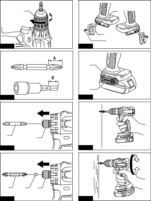
Fig.1 |
Fig.5 |
|
1 |
|
|
A |
B |
|
2 |
1 |
|
|
|
Fig.2 |
Fig.6 |
|
|
1 |
|
|
|
1 |
Fig.3 |
|
Fig.7 |
|
|
1 |
|
|
2 |
|
1 |
3 |
|
|
|
Fig.4 |
|
Fig.8 |
2
1 |
3 |
1 |
|
|
|
|
2 |
|
|
|
2 |
|
|
3 |
Fig.9 |
|
Fig.13 |
|
1 |
|
2 |
Fig.10 |
Fig.14 |
1 |
2 |
|
|
Fig.11 |
|
|
|
Fig.15 |
1 |
2 |
3 |
Fig.12 |
|
Fig.16 |
3

ENGLISH (Original instructions)
SPECIFICATIONS
Model: |
|
DDF483 |
DDF083 |
||
Drilling capacities |
Steel |
|
13 mm |
|
|
|
Wood |
|
36 mm |
|
|
Fastening capacities |
Wood screw |
|
6 mm x 75 mm |
|
|
|
Machine screw |
|
M6 |
|
|
No load speed |
High (2) |
|
0 - 1,700 min-1 |
|
|
|
Low (1) |
|
0 - 500 min-1 |
|
|
Overall length |
|
162 mm |
124 mm |
||
Rated voltage |
|
|
D.C. 18 V |
|
|
Battery cartridge |
|
BL1815N, BL1820, |
BL1830, BL1830B, |
BL1815N, BL1820, |
BL1830, BL1830B, |
|
|
BL1820B |
BL1840, BL1840B, |
BL1820B |
BL1840, BL1840B, |
|
|
|
BL1850, BL1850B, |
|
BL1850, BL1850B, |
|
|
|
BL1860B |
|
BL1860B |
Net weight |
|
1.3 kg |
1.5 kg |
1.1 kg |
1.3 kg |
•Due to our continuing program of research and development, the specifications herein are subject to change without notice.
•Specifications and battery cartridge may differ from country to country.
•Weight, with battery cartridge, according to EPTA-Procedure 01/2003
Intended use
The tool is intended for drilling and screw driving in wood, metal and plastic.
Noise
The typical A-weighted noise level determined according to EN60745:
Sound pressure level (LpA) : 77 dB(A) Uncertainty (K) : 3 dB(A)
The noise level under working may exceed 80 dB (A).

 WARNING: Wear ear protection.
Vibration
The vibration total value (tri-axial vector sum) determined according to EN60745:
Work mode: drilling into metal
Vibration emission (ah,D) : 2.5 m/s2 or less Uncertainty (K) : 1.5 m/s2
NOTE: The declared vibration emission value has been measured in accordance with the standard test method and may be used for comparing one tool with another.
NOTE: The declared vibration emission value may also be used in a preliminary assessment of exposure.
 WARNING: The vibration emission during actual use of the power tool can differ from the declared emission value depending on the ways in which the tool is used.
 WARNING: Be sure to identify safety measures to protect the operator that are based on an estimation of exposure in the actual conditions of use (taking account of all parts of the operating cycle such as the times when the tool is switched off and when it is running idle in addition to the trigger time).
EC Declaration of Conformity
For European countries only
The EC declaration of conformity is included as Annex A to this instruction manual.
SAFETY WARNINGS
General power tool safety warnings
 WARNING: Read all safety warnings and all instructions. Failure to follow the warnings and instructions may result in electric shock, fire and/or serious injury.
Save all warnings and instructions for future reference.
The term "power tool" in the warnings refers to your mains-operated (corded) power tool or battery-operated
(cordless) power tool.
4 ENGLISH

Cordless driver drill safety warnings
1.Use auxiliary handle(s), if supplied with the tool. Loss of control can cause personal injury.
2.Hold power tool by insulated gripping surfaces, when performing an operation where the cutting accessory may contact hidden wiring. Cutting accessory contacting a "live" wire may make exposed metal parts of the power tool "live" and could give the operator an electric shock.
3.Hold power tool by insulated gripping surfaces, when performing an operation where the fastener may contact hidden wiring.
Fasteners contacting a "live" wire may make exposed metal parts of the power tool "live" and could give the operator an electric shock.
4.Always be sure you have a firm footing. Be sure no one is below when using the tool in high locations.
5.Hold the tool firmly.
6.Keep hands away from rotating parts.
7.Do not leave the tool running. Operate the tool only when hand-held.
8.Do not touch the drill bit or the workpiece immediately after operation; they may be extremely hot and could burn your skin.
9.Some material contains chemicals which may be toxic. Take caution to prevent dust inhalation and skin contact. Follow material supplier safety data.
SAVE THESE INSTRUCTIONS.
 WARNING: DO NOT let comfort or familiarity with product (gained from repeated use) replace strict adherence to safety rules for the subject product. MISUSE or failure to follow the safety rules stated in this instruction manual may cause serious personal injury.
Important safety instructions for battery cartridge
1.Before using battery cartridge, read all instructions and cautionary markings on (1) battery charger, (2) battery, and (3) product using battery.
2.Do not disassemble battery cartridge.
3.If operating time has become excessively shorter, stop operating immediately. It may result in a risk of overheating, possible burns and even an explosion.
4.If electrolyte gets into your eyes, rinse them out with clear water and seek medical attention right away. It may result in loss of your eyesight.
5.Do not short the battery cartridge:
(1)Do not touch the terminals with any conductive material.
(2)Avoid storing battery cartridge in a container with other metal objects such as nails, coins, etc.
(3)Do not expose battery cartridge to water or rain.
A battery short can cause a large current flow, overheating, possible burns and even a breakdown.
6.Do not store the tool and battery cartridge in locations where the temperature may reach or exceed 50 °C (122 °F).
7.Do not incinerate the battery cartridge even if it is severely damaged or is completely worn out. The battery cartridge can explode in a fire.
8.Be careful not to drop or strike battery.
9.Do not use a damaged battery.
10.The contained lithium-ion batteries are subject to the Dangerous Goods Legislation requirements.
For commercial transports e.g. by third parties, forwarding agents, special requirement on packaging and labeling must be observed.
For preparation of the item being shipped, consulting an expert for hazardous material is required. Please also observe possibly more detailed national regulations.
Tape or mask off open contacts and pack up the battery in such a manner that it cannot move around in the packaging.
11.Follow your local regulations relating to disposal of battery.
SAVE THESE INSTRUCTIONS.
 CAUTION: Only use genuine Makita batteries.
Use of non-genuine Makita batteries, or batteries that have been altered, may result in the battery bursting causing fires, personal injury and damage. It will also void the Makita warranty for the Makita tool and charger.
Tips for maintaining maximum battery life
1.Charge the battery cartridge before completely discharged. Always stop tool operation and charge the battery cartridge when you notice less tool power.
2.Never recharge a fully charged battery cartridge. Overcharging shortens the battery service life.
3.Charge the battery cartridge with room temperature at 10 °C - 40 °C (50 °F - 104 °F). Let a hot battery cartridge cool down before charging it.
4.Charge the battery cartridge if you do not use it for a long period (more than six months).
5 ENGLISH

FUNCTIONAL
DESCRIPTION
 CAUTION: Always be sure that the tool is switched off and the battery cartridge is removed before adjusting or checking function on the tool.
Installing or removing battery cartridge
 CAUTION: Always switch off the tool before installing or removing of the battery cartridge.
 CAUTION: Hold the tool and the battery cartridge firmly when installing or removing battery cartridge. Failure to hold the tool and the battery cartridge firmly may cause them to slip off your hands and result in damage to the tool and battery cartridge and a personal injury.
► Fig.1: 1. Red indicator 2. Button 3. Battery cartridge
To remove the battery cartridge, slide it from the tool while sliding the button on the front of the cartridge.
To install the battery cartridge, align the tongue on the battery cartridge with the groove in the housing and slip it into place. Insert it all the way until it locks in place with a little click. If you can see the red indicator on the upper side of the button, it is not locked completely.
 CAUTION: Always install the battery cartridge fully until the red indicator cannot be seen. If not, it may accidentally fall out of the tool, causing injury to you or someone around you.
 CAUTION: Do not install the battery cartridge forcibly. If the cartridge does not slide in easily, it is not being inserted correctly.
Indicating the remaining battery capacity
Only for battery cartridges with "B" at the end of the model number
► Fig.2: 1. Indicator lamps 2. Check button
Press the check button on the battery cartridge to indicate the remaining battery capacity. The indicator lamps light up for few seconds.
|
|
|
Indicator lamps |
|
|
|
Remaining |
|||||||
|
|
|
|
|
|
|
|
|
|
|
|
|
|
capacity |
|
|
|
|
|
|
|
|
|
|
|
|
|
|
|
Lighted |
|
|
|
|
Off |
|
||||||||
|
|
|
|
|
|
|
|
|
|
|
|
|
|
75% to 100% |
|
|
|
|
|
|
|
|
|
|
|
|
|
|
|
|
|
|
|
|
|
|
|
|
|
|
|
|
|
|
|
|
|
|
|
|
|
|
|
|
|
|
|
|
|
|
|
|
|
|
|
|
|
|
|
|
|
|
|
50% to 75% |
|
|
|
|
|
|
|
|
|
|
|
|
|
|
|
|
|
|
|
|
|
|
|
|
|
|
|
|
|
|
|
|
|
|
|
|
|
|
|
|
|
|
|
|
|
|
|
|
|
|
|
|
|
|
|
|
|
|
|
25% to 50% |
|
|
|
|
|
|
|
|
|
|
|
|
|
|
|
|
|
|
|
|
|
|
|
|
|
|
|
|
|
|
|
|
|
|
|
|
|
|
|
|
|
|
|
|
|
|
|
|
|
|
|
|
|
|
|
|
|
|
|
0% to 25% |
|
|
|
|
|
|
|
|
|
|
|
|
|
|
|
|
|
|
|
|
|
|
|
|
|
|
|
|
|
|
|
|
|
|
|
|
|
|
|
|
|
|
|
|
|
NOTE: Depending on the conditions of use and the ambient temperature, the indication may differ slightly from the actual capacity.
Tool / battery protection system
The tool is equipped with a tool/battery protection system. This system automatically cuts off power to the motor to extend tool and battery life. The tool will automatically stop during operation if the tool or battery is placed under one of the following conditions:
Overload protection
When the tool/battery is operated in a manner that causes it to draw an abnormally high current, the tool automatically stops without any indication. In this situation, turn the tool off and stop the application that caused the tool to become overloaded. Then turn the tool on to restart.
Overheat protection
When the tool/battery is overheated, the tool stops automatically. In this situation, let the tool/battery cool before turning the tool on again.
Overdischarge protection
When the battery capacity is not enough, the tool stops automatically. In this case, remove the battery from the tool and charge the battery.
NOTE: Overheat protection (for battery) will work only with batteries with star marking.
► Fig.3: 1. Star marking
Switch action
► Fig.4: 1. Switch trigger
 CAUTION: Before installing the battery cartridge into the tool, always check to see that the switch trigger actuates properly and returns to the "OFF" position when released.
To start the tool, simply pull the switch trigger. Tool speed is increased by increasing pressure on the switch trigger. Release the switch trigger to stop.
NOTE: The tool automatically stops if you keep pulling the switch trigger for about 6 minutes.
Lighting up the front lamp
► Fig.5: 1. Lamp
 CAUTION: Do not look in the light or see the source of light directly.
Pull the switch trigger to light up the lamp. The lamp keeps on lighting while the switch trigger is being pulled. The lamp goes out approximately 10 seconds after releasing the switch trigger.
6 ENGLISH

NOTE: When the tool is overheated, the tool stops automatically and the lamp starts flashing. In this case, release the switch trigger. The lamp turns off in one minute.
NOTE: Use a dry cloth to wipe the dirt off the lens of the lamp. Be careful not to scratch the lens of lamp, or it may lower the illumination.
Reversing switch action
► Fig.6: 1. Reversing switch lever
 CAUTION: Always check the direction of rotation before operation.
 CAUTION: Use the reversing switch only after the tool comes to a complete stop. Changing the direction of rotation before the tool stops may damage the tool.
 CAUTION: When not operating the tool, always set the reversing switch lever to the neutral position.
This tool has a reversing switch to change the direction of rotation. Depress the reversing switch lever from the A side for clockwise rotation or from the B side for counterclockwise rotation.
When the reversing switch lever is in the neutral position, the switch trigger cannot be pulled.
Speed change
► Fig.7: 1. Speed change lever
 CAUTION: Always set the speed change lever fully to the correct position. If you operate the
tool with the speed change lever positioned halfway between the "1" side and "2" side, the tool may be damaged.
 CAUTION: Do not use the speed change lever while the tool is running. The tool may be damaged.
Displayed |
Speed |
Torque |
Applicable |
Number |
|
|
operation |
1 |
Low |
High |
Heavy load- |
|
|
|
ing operation |
2 |
High |
Low |
Light loading |
|
|
|
operation |
To change the speed, switch off the tool first. Push the speed change lever to display "2" for high speed or "1" for low speed but high torque. Be sure that the speed change lever is set to the correct position before operation.
If the tool speed is coming down extremely during the operation with display "2", push the lever to display "1" and restart the operation.
Adjusting the fastening torque
► Fig.8: 1. Adjusting ring 2. Graduation 3. Arrow
The fastening torque can be adjusted in 21 levels by turning the adjusting ring. Align the graduations with the arrow
on the tool body. You can get the minimum fastening torque at 1 and maximum torque at  marking. The clutch will slip at various torque levels when set at the number 1 to 20. The clutch does not work at
the |
marking. |
|
|
|
|
|
|
|
|
|
|
|
|
|
|
|
|
|
|
|
|
|
|
|
|
Before actual operation, drive a trial screw into your material or a piece of duplicate material to determine which |
|
||||||||||||||||||||||||
torque level is required for a particular application. |
|
|
|
|
|
|
|
|
|
|
|
|
|
|
|
|
|||||||||
The following shows the rough guide of the relationship between the screw size and graduation. |
|
|
|
|
|
||||||||||||||||||||
|
|
|
|
|
|
|
|
|
|
|
|
|
|
|
|
|
|
|
|
|
|
|
|
|
|
Graduation |
|
1 |
2 |
|
3 |
4 |
5 |
6 |
7 |
8 |
|
9 |
10 |
11 |
12 |
13 |
14 |
15 |
16 |
17 |
18 |
|
19 |
20 |
|
Machine screw |
|
|
M4 |
|
|
|
|
|
|
M5 |
|
|
|
|
|
|
|
M6 |
|
|
|
|
|||
|
Wood |
Soft wood |
|
|
|
– |
|
|
|
ɸ3.5 x 22 |
|
ɸ4.1x 38 |
|
|
|
|
– |
|
|
|
|
||||
|
screw |
(e.g. pine) |
|
|
|
|
|
|
|
|
|
|
|
|
|
|
|
|
|
|
|
|
|
|
|
|
|
Hard wood |
|
|
|
– |
|
|
|
|
|
ɸ3.5 x 22 |
|
|
|
ɸ4.1x 38 |
|
|
|
– |
|
||||
|
|
(e.g. lauan) |
|
|
|
|
|
|
|
|
|
|
|
|
|
|
|
|
|
|
|
|
|
|
|
ASSEMBLY
 CAUTION: Always be sure that the tool is switched off and the battery cartridge is removed before carrying out any work on the tool.
Installing or removing driver bit/ drill bit
For Model DDF483 (optional accessory)
► Fig.9: 1. Sleeve 2. Close 3. Open
Turn the sleeve counterclockwise to open the chuck jaws. Place the driver bit/drill bit in the chuck as far as it will go. Turn the sleeve clockwise to tighten the chuck. To remove the driver bit/drill bit, turn the sleeve counterclockwise.
7 ENGLISH
 Loading...