


SCH-I-O Rev A
Installation & Operation
Manual
SCH Collectors
WARNING:
This manual must only be used by a qualified heating installer/service technician. Read all instructions before installing. Perform steps in the order given. Failure to comply could result in severe personal injury, death, or substantial property damage.
Contents
HAZARD DEFINITIONS . . . . . . . . . . . . . . . . . . . . . . . . . . 2 1. INTRODUCTION. . . . . . . . . . . . . . . . . . . . . . . . . . . . 3-6 Technical Data . . . . . . . . . . . . . . . . . . . . . . . . . . . . . . . . . . 3 How It Works . . . . . . . . . . . . . . . . . . . . . . . . . . . . . . . . . . . 4 Components . . . . . . . . . . . . . . . . . . . . . . . . . . . . . . . . . . . . 4 Descriptions . . . . . . . . . . . . . . . . . . . . . . . . . . . . . . . . . . . . 4
2. LOCATION
Array Options . . . . . . . . . . . . . . . . . . . . . . . . . . . . . . . . . . . 7 Installation Positions . . . . . . . . . . . . . . . . . . . . . . . . . . . . . 8 Handling and Storing . . . . . . . . . . . . . . . . . . . . . . . . . . . . . 9 What to Avoid. . . . . . . . . . . . . . . . . . . . . . . . . . . . . . . . . . . 9
3. ROOF ATTACHMENT INSTALLATION
Roof Attachment Types . . . . . . . . . . . . . . . . . . . . . . . . . . 10 Roof Attachment Quantities for SCH Collectors . . . . . . . 11 Roof Attachment Spacing Distance . . . . . . . . . . . . . . . . . 12 Installation of Roof Attachment Types . . . . . . . . . . . . 13-27
4. COLLECTION INSTALLATION
Horizontal Bar Lengths. . . . . . . . . . . . . . . . . . . . . . . . . . . 28 Spacing Information . . . . . . . . . . . . . . . . . . . . . . . . . . . . . 28 SCH Parallel Mounting Instructions . . . . . . . . . . . . . . 29-31 SCH Inclined / Non-South Facing Mounting Instructions 32-34 SCH Frame Dimensions . . . . . . . . . . . . . . . . . . . . . . . . . 35 SCH Mounting Hardware + Hydraulic Connection Kits . . 36
5. HYDRAULIC CONNECTIONS
SCH Connections Kits . . . . . . . . . . . . . . . . . . . . . . . . . . . 37
Hydraulic Expansion Kits . . . . . . . . . . . . . . . . . . . . . . 37-38
Pressure Drop Chart . . . . . . . . . . . . . . . . . . . . . . . . . . . . 39
6. SYSTEM STARTUP
Startup . . . . . . . . . . . . . . . . . . . . . . . . . . . . . . . . . . . . . . . 40
Filling, Flushing and Bleeding . . . . . . . . . . . . . . . . . . . . . 40
Clamp Ring Screw Connections . . . . . . . . . . . . . . . . . . . 41
Flat Seal Screw Connections. . . . . . . . . . . . . . . . . . . . . . 41
Operation, Multi-function Ball Valve & Check Valve . . . . 41
7. MAINTENANCE
Fluid Installation . . . . . . . . . . . . . . . . . . . . . . . . . . . . . . . . 42
System Design Considerations . . . . . . . . . . . . . . . . . . . . 42
Technical Data . . . . . . . . . . . . . . . . . . . . . . . . . . . . . . . . . 42
Solar Circuit . . . . . . . . . . . . . . . . . . . . . . . . . . . . . . . . . . . 43
Collector . . . . . . . . . . . . . . . . . . . . . . . . . . . . . . . . . . . . . . 43
Pump / Control Function . . . . . . . . . . . . . . . . . . . . . . . . . 43
Control Settings . . . . . . . . . . . . . . . . . . . . . . . . . . . . . . . . 43
Revision Notes . . . . . . . . . . . . . . . . . . . . . . . . . Back Cover
Hazard definitions
The following defined terms are used throughout this manual to bring attention to the presence of hazards of various risk levels or to important information concerning the life of the product.
DANGER
WARNING
CAUTION
CAUTION
NOTICE
DANGER indicates an imminently hazardous situation which, if not avoided, will result in death or serious injury.
WARNING indicates a potentially hazardous situation which, if not avoided, could result in death or serious injury.
CAUTION indicates a potentially hazardous situation which, if not avoided, may result in minor or moderate injury.
CAUTION used without the safety alert symbol indicates a potentially hazardous situation which, if not avoided, may result in property damage.
NOTICE indicates special instructions on installation, operation, or maintenance that are important but not related to personal injury or property damage.
2

SCH Collectors Installation & Operation Manual
1 Introduction
The SCH collector is suitable for parallel installations and inclined installations on pitched and flat roofs as well as freestanding on the ground. It is available as a single-piece large collector in sizes ranging from 65 to 130 ft2 with inlet and outlet connections of
.86" in diameter. Suitable mounting systems are available for various types of roofing. The SCH collector is delivered in standard lengths of 9'-10" to 19'-7" and a height of 6'-7", resulting in gross surface areas between 65 and 130 ft².
Area of use: Parallel, inclined, on roof mounting, on tiles, plain tiles, slate, Spanish tiles, tin roofing, flat roofs, and as a freestanding unit
Technical data
|
|
|
|
SCH Collector |
|
|
|
|
|
|
|
|
|
||
Type |
|
|
SCH065 |
|
SCH090 |
|
|
SCH110 |
|
|
SCH130 |
||||
|
|
|
|
|
|
|
|
|
|
|
|
|
|
|
|
Quantity of Glass Panels |
|
3 |
|
4 |
|
|
5 |
|
|
|
6 |
|
|||
Gross area |
|
|
65.66 ft2 |
|
87.19 ft2 |
|
108.72 ft2 |
|
|
130.24 ft2 |
|||||
Aperture surface area |
|
58.45 ft2 |
|
77.93 ft2 |
|
97.95 ft2 |
|
|
116.90 ft2 |
||||||
Absorber surface area |
|
59.85 ft2 |
|
79.76 ft2 |
|
99.67 ft2 |
|
|
119.59 ft2 |
||||||
External Dimensions (L x W)1 |
|
6'-7" x 9'-10" |
|
6'-7" x 13'-2" |
|
6'-7" x 16'-4" |
|
6'-7" x 19'-7" |
|||||||
Weight Ratings |
|
|
309 lbs. |
|
411 lbs. |
|
|
513 lbs. |
|
|
614 lbs. |
||||
|
|
|
|
|
|
|
|
|
|
|
|
|
|
||
SCH mounting hardware + hydraulic connection kits |
|
|
|
|
|
|
|
|
|
||||||
|
|
|
|
|
|
|
|
|
|
|
|
|
|||
|
Part-number |
Description |
|
|
|
|
Needed quantities for: |
|
|||||||
|
|
|
|
SCH065 |
|
SCH090 |
|
SCH110 |
SCH130 |
|
|||||
|
|
|
|
|
|
|
|
|
|
||||||
|
Parallel installation: |
|
|
|
|
|
|
|
|
|
|
|
|
||
|
SCA20001 |
Horizontal aluminum bar 10 ft |
|
2 |
|
|
|
|
|
|
|
||||
|
SCA20002 |
Horizontal aluminum bar 13 ft |
|
|
|
|
2 |
|
|
|
|
|
|||
|
SCA20003 |
Horizontal aluminum bar 16 ft |
|
|
|
|
|
|
2 |
|
|
||||
|
SCA20004 |
Horizontal aluminum bar 20 ft |
|
|
|
|
|
|
|
|
2 |
|
|||
|
SSK20004 |
End bracing kit |
|
|
|
2 |
|
2 |
|
2 |
2 |
|
|||
|
SSK20005 |
Z-hook kit |
|
|
|
2 |
|
3 |
|
3 |
3 |
|
|||
|
|
|
|
|
|
|
|
|
|
|
|
|
|||
|
Inclined (20°,40°,60°) installation: |
|
|
|
|
|
|
|
|
|
|
||||
|
SCA20001 |
Horizontal aluminum bar 10 ft |
|
2 |
|
|
|
|
|
|
|
||||
|
SCA20002 |
Horizontal aluminum bar 13 ft |
|
|
|
|
2 |
|
|
|
|
|
|||
|
SCA20003 |
Horizontal aluminum bar 16 ft |
|
|
|
|
|
|
2 |
|
|
||||
|
SCA20004 |
Horizontal aluminum bar 20 ft |
|
|
|
|
|
|
|
|
2 |
|
|||
|
SCA20005 |
Aluminum U-channel 10 ft |
|
3 |
|
|
|
|
|
|
|
||||
|
SCA20006 |
Aluminum U-channel 13 ft |
|
|
|
|
3 |
|
|
|
|
|
|||
|
SCA20007 |
Aluminum U-channel 16 ft |
|
|
|
|
|
|
3 |
|
|
||||
|
SCA20008 |
Aluminum U-channel 20 ft |
|
|
|
|
|
|
|
|
3 |
|
|||
|
SSK20001 |
A-frame 20° inclined |
|
2 |
|
3 |
|
3 |
4 |
|
|||||
|
SSK20002 |
A-frame 40° inclined |
|
2 |
|
3 |
|
3 |
4 |
|
|||||
|
SSK20003 |
A-frame 60° inclined |
|
2 |
|
3 |
|
3 |
4 |
|
|||||
|
|
|
|
|
|
|
|
|
|
|
|
|
|||
|
Hydraulic connection kits: (1 array is max. 2 SCH’s!) |
|
|
|
|
|
|
|
|
|
|
||||
|
HYK20001 |
Hydr. conn. kit 2x 6.5' + plug + sensor well |
|
1x per collector or array |
|
||||||||||
|
HYK20002 |
Hydr. conn. kit 1x 6.5'/1x 13' + plug + sensor well |
|
1x per collector or array |
|
||||||||||
|
HYK20003 |
Serial hydr. exp. kit for stacked installation |
|
|
|
1x per array |
|
|
|||||||
|
HYK20004 |
Parallel hydr. exp. kit for side by side installation |
|
|
|
1x per array |
|
|
|||||||
|
HYK20005 |
Serial hydr. exp. kit for side by side installation |
|
|
|
1x per array |
|
|
|||||||
|
|
|
|
|
|
|
|
|
|
|
|
||||
|
Mechanical connection kits: (optional for installation!) |
|
|
|
|
|
|
|
|
|
|||||
|
MCK20001 |
Mechanical conn. kit for side by side installation |
|
|
|
1x per array |
|
|
|||||||
|
MCK20002 |
Mechanical conn. kit for stacked installation |
|
|
|
1x per array |
|
|
|||||||
|
MCK20003 |
Cover for piping (for side by side installations) |
|
|
|
1x per array |
|
|
|||||||
|
|
|
|
|
|
|
|
|
|
|
|
||||
|
Gable bracing kits: (required for non-south facing installation!) |
|
|
|
|
|
|
|
|
|
|||||
|
GBK20003 |
Bracing kit w/ diagonal support |
|
|
|
|
1x per collector |
|
|
||||||
3
1 Introduction
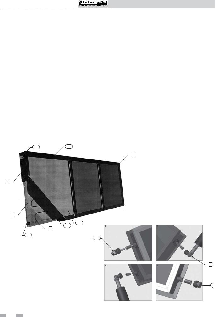
How it works...
1.Housing
Powder coated (RAL7016)aluminum frame structure with PU rigid foam and an aluminum rear wall.
2.Cover
Prismatic solar safety glass, .15" thick, for maximum light transmission.
3.Insulation
.76" heat resistant, special PU rigid foam and 1.57" mineral wool with high pressure resistance, emission free, nonflammable.
4.Absorber
Full surface absorber, laser welded with highly-selective PVD coating (PVD = Physical Vapor Deposition), serpentine flow.
5.Collector seal
Aluminum profile system with double temperature and UVresistant silicone seals, emission free.
SCH Collector
7 |
1 |
 5
5 

 3
3 


 2 4
2 4
 8
8 
6
10
SCH Collectors Installation & Operation Manual
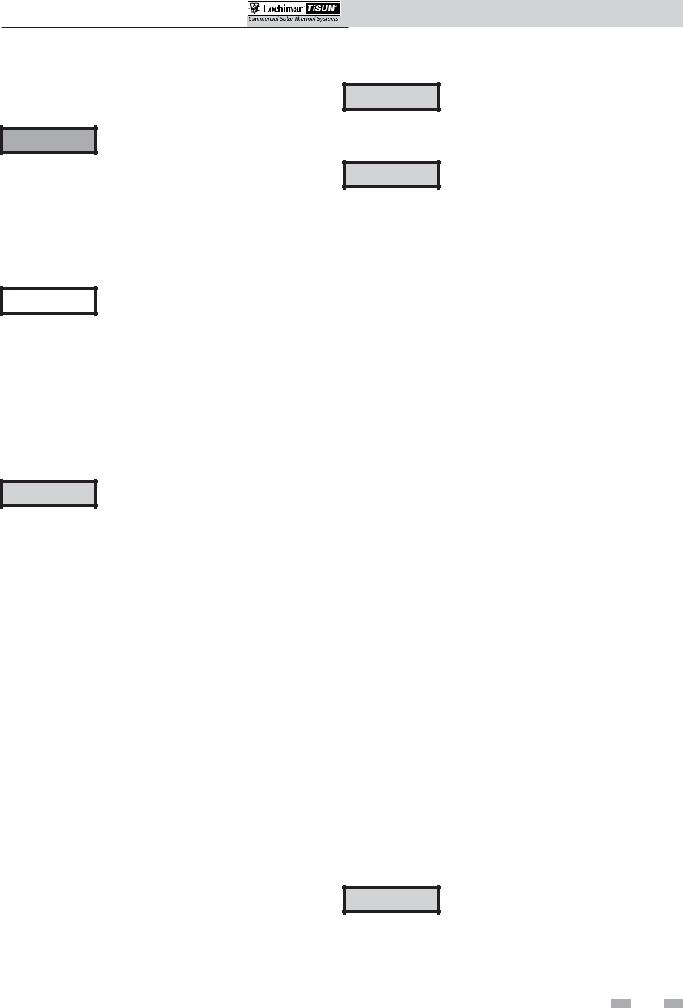
6.Inlet connection
Copper pipes, .86" diameter.
7.Outlet connection
Copper pipes, .86" diameter.
8.Absorber coils
10 mm copper, serpentine arrangement.
9.Hydraulic connection kit
Connection set with stainless steel corrugated pipe. For connecting the collector supply and return to the riser. The corrugated pipes are available in kits with 2 x 6'-7" or 2 x 13'1" length including sensor well and plug.
10.Sensor well
For measuring the collector outlet temperature directly in the fluid. The sensor well can be installed on the outlet connection as shown on the collector label. The sensor must be inserted up to the end of the sensor well.
11.Plug
This plug is used on the end collector of each array to complete the water flow path.
 7
7
 9
9 
11
4
1 Introduction (continued)
Before getting started on your installation be sure to carefully read the preparation instructions in this section.
WARNING
NOTICE
CAUTION
Installer – Read all instructions, including this manual before installing. Perform steps in the order given.
Have your collector(s) serviced/inspected by a qualified service technician, at least annually.
Failure to comply with the above could result in severe personal injury, death or substantial property damage.
When calling or writing about the collector
– Please have the collector model and serial number.
Any claims for damage or shortage in shipment must be filed immediately against the transportation company by the consignee.
Factory warranty (shipped with the collector) does not apply to collectors improperly installed or improperly operated.
•You must comply with local regulations, laws and standards of the local governing authority.
•The frame must be capable of withstanding the local snow and wind loads and permit the correct anchoring of the collectors in accordance with all applicable local regulations.
•The load bearing capacity of the roofing and the frame shall be specially checked or analyzed by a structural engineer.
•The number of mounting brackets specified by the Lochinvar/TiSun manuals and parts sheets is based on an average collector load bearing per square foot. The maximum permissible collector loading per square foot may be calculated from the number of mounting brackets, taking into consideration the permissible loading on the mounting brackets. If a higher collector wind and snow loading (including snow sliding off the roof) per square foot is required, additional mounting brackets will have to be used. Roof pitches in excess of 30° also represent increased loading; additional mounting brackets must also be used for this variant.
SCH Collectors Installation & Operation Manual
Lochinvar/TiSun Solar Thermal CollectorsCAUTION are not specifically designed for drain back
installations. Consult the factory if drain back utilization is necessary.
CAUTION • The mounting substructure must be capable of withstanding the local
snow and wind loads and permit correct anchoring of the collectors.
•To avoid damage to the collectors and mounting frames from snow sliding off the roof, additional snow guards must be placed in sufficient numbers around the collectors and above the collectors.
•The collectors must be linked with a lightning arrester system and/or the building’s ground system by a licensed electrician.
•Hydraulic connection of the collectors must be performed according to Lochinvar/TiSun specifications.
•The collector connections must not be damaged,soiledormisaligned. Takecare during transport, installation, and connection of the modules. Do not remove the header protection caps at the top and bottom connections of the collector until just before installation.
•When connecting the modules to the riser, the Hydraulic Connection Kit (corrugated pipe) supplied must be installed. Otherwise, the warranty is invalidated.
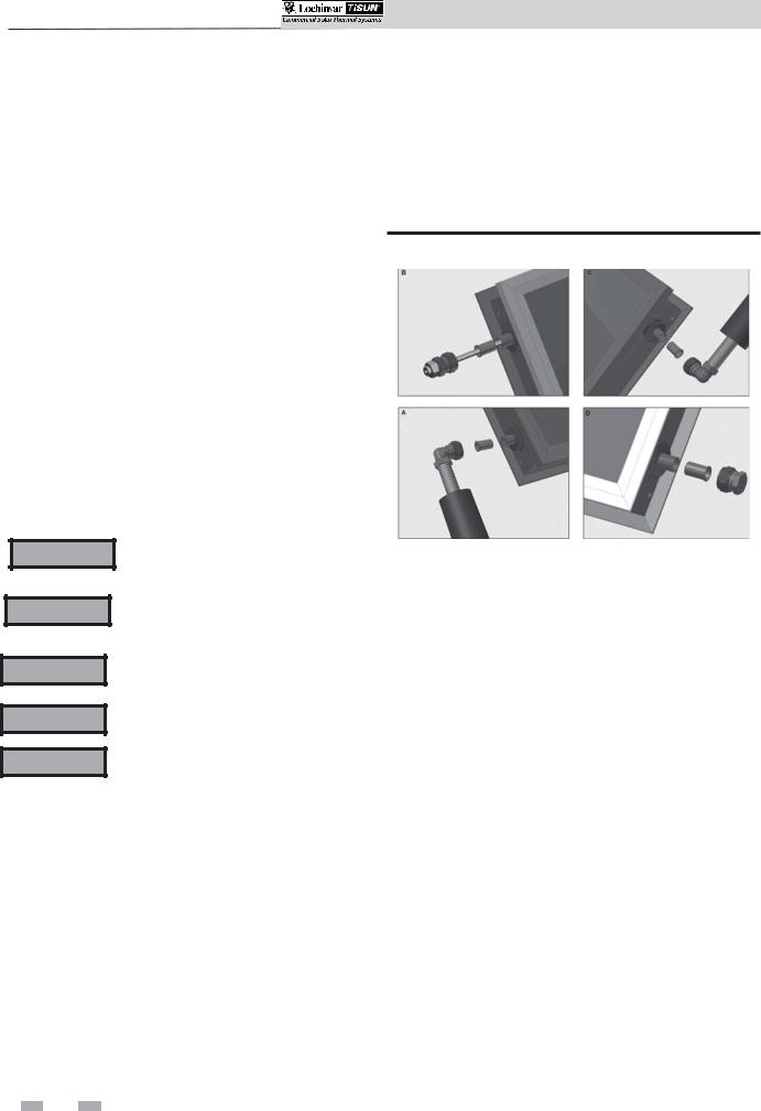
•Always connect the collector outlet and inlet flow to each other diagonally,
|
please |
follow |
the |
connection |
|
example (see FIG. 1-1 on page 6). |
|||
• |
Do not twist the headers when screwing |
|||
|
theconnectionstogether. Holdthreaded |
|||
|
connection in the desired position and |
|||
|
tighten clamping ring union nut to |
|||
|
torque. |
|
|
|
• |
Roof penetrations for solar piping must |
|||
|
be adequately sealed against water ingress. |
|||
• |
Use only the original sensor well |
|||
|
supplied. |
|
|
|
• |
Use only high temperature and glycol |
|||
|
pipe sealing materials. |
|
||
CAUTION All piping should be properly insulated to avoid freezing and/or burn potential.
5
SCH Collectors Installation & Operation Manual
1 Introduction
NOTICE |
• Check the materials for any damage |
sustainedintransportanddescribeany |
|
|
damage in writing on the packing slip |
|
where necessary. This is important to |
|
process any needed freight or delivery |
|
damage claims. |
• Carefully read through the relevant installation instructions before starting the installation and follow each step.
• Use only the original mounting components.
• Stainless steel screws may not be used again once they have been removed (because of the possibility of breaking).
• Any conversion or modification of the Lochinvar/TiSun product not expressly approved in writing by the manufacturer shall void the warranty.
• No liability can be accepted for damage resulting from failure to observe the installation instructions.
WARNING Only authorized solar companies familiar with our products may handle them.
There is a risk of injury when handlingWARNING collectors and mounting accessories as
these have sharp edges.
WARNING
WARNING
WARNING
The collector becomes very hot in the sunlight. There is a risk of burn.
Comply with all safety regulations and applicable OSHA requirements.
Check the load bearing capacity and stability of the substructure onto which the collector is to be installed and will need to be accessed during the installation process.
|
WARNING |
A properly sized expansion tank must be |
|
used to avoid damage to the Solar Thermal |
|
|
|
System. |
|
|
If copper pipe is being used, all joints |
|
WARNING |
|
|
|
MUST BE brazed, no soldering allowed. |
Figure 1-1 Connection Diagram
Dismantling and Disposal
•The units are dismantled in the reverse sequence of installation.
•The roofing shall be properly sealed after the mounting brackets have been removed.
•Materials shall be disposed of in an environmentally conscious manner.
6
SCH Collectors Installation & Operation Manual
2 Location
Array options
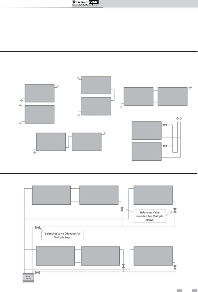
For series and parallel connection of multiple collectors, it is advisable to calculate the pressure drop over the entire system with the aid of the enclosed documents and to install an appropriate pump if necessary. The maximum collector area per collector array connected in series is 260 ft2. Be aware of pressure drop, reference the array options (FIG.’s 2-1 and 2-2).
Figure 2-1 Array Piping
SERIES STACKED
SINGLE COLLECTOR
PARALLEL SIDE BY SIDE
PARALLEL WITH BALANCING VALVES
(ON ROOF ONLY)
SERIES SIDE BY SIDE
Figure 2-2 Multiple Array Piping
7
SCH Collectors Installation & Operation Manual
2 Location
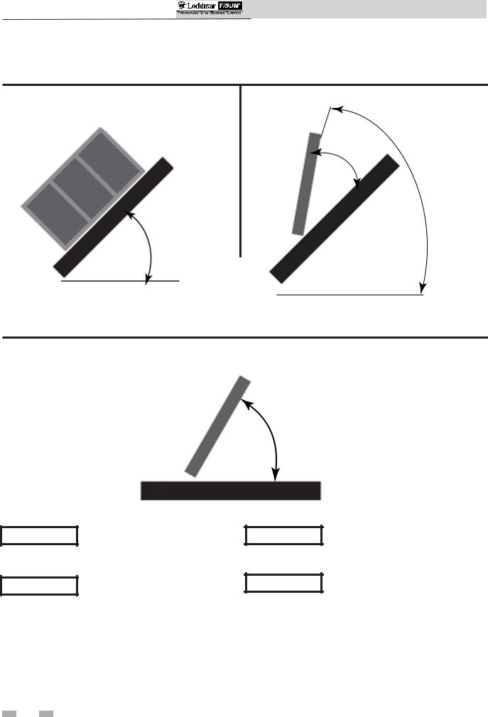
Installation positions
Figure 2-3 SCH Parallel Installations |
Figure 2-4 SCH Inclined Installations |
20°/40°/60°
min. 15° - max. 70°
min. 15° - max. 70°
Figure 2-5 SCH Freestanding Installations
min. 15° - max. 70°
NOTICE
NOTICE
For best performance, it is recommended that the collectors face true south.
It is not recommended for the collector field to deviate any further than 45° from true south.
NOTICE
NOTICE
Collector incline should be at least 15° and no more than 70° for best performance.
Avoid installation in shaded areas. Shaded areas will reduce the performance of the solar collectors.
8
SCH Collectors Installation & Operation Manual
2 Location (continued) |
|
|
|
|
|
|
|
|
|
|
|
||||
Handling and storing |
|
|
|
|
|
• |
Only loosen |
the |
crane connection |
||||||
|
|
|
|
WARNING |
|||||||||||
WARNING |
|
|
|
|
|
|
|
|
|
when the collectors are completely |
|||||
|
• |
Installation of LOCHINVAR/TiSun |
|
|
|||||||||||
|
|
|
fixed to the substructure. |
|
|
||||||||||
|
|
|
SCH collectors is only allowed for |
|
|
• |
Pay special |
attention to |
roof-work |
||||||
|
|
|
professional staff. |
|
|
|
|||||||||
|
|
|
|
|
|
|
near an electric grid. If need be, the |
||||||||
|
|
• Local instructions, laws and standards |
|
|
|||||||||||
|
|
|
|
constructor |
must |
take |
security |
||||||||
|
|
|
are to be kept. |
|
|
|
|
|
|||||||
|
|
|
|
|
|
|
|
precautions |
such |
as |
isolation, |
||||
|
|
• |
Collectors |
are |
to be |
located |
so |
|
|
||||||
|
|
|
|
covering, etc. |
|
|
|
|
|||||||
|
|
|
falling of |
snow |
and ice does |
not |
|
|
|
|
|
|
|||
|
|
|
|
• Inspect the roof surface in the area of |
|||||||||||
|
|
|
endanger any person or property. |
|
|
||||||||||
|
|
|
|
|
|
the installation |
for |
cracks, |
water |
||||||
|
|
• |
Use personal protection |
equipment |
|
|
|||||||||
|
|
|
|
leakage, and roofing material quality |
|||||||||||
|
|
|
(helmet, belt, security shoes) when on |
|
|
||||||||||
|
|
|
|
|
and uniformity. |
This is |
especially |
||||||||
|
|
|
the roof. |
|
|
|
|
|
|
||||||
|
|
|
|
|
|
|
|
|
important if the roof is more than 10 |
||||||
|
|
• Secure tools and materials against |
|
|
|
||||||||||
|
|
|
|
|
years old. |
|
|
|
|
|
|||||
|
|
|
falls. |
|
|
|
|
|
|
|
|
|
|
|
|
|
|
|
|
|
|
|
|
• |
Inspect the roof for sags and other |
||||||
|
|
• It is forbidden to stand under |
|
|
|||||||||||
|
|
|
|
|
abnormalities. |
A |
sag |
or |
deep |
||||||
|
|
|
hanging load. |
|
|
|
|
|
|||||||
|
|
|
|
|
|
|
|
depression in the roof may indicate a |
|||||||
|
|
|
|
|
|
|
|
|
|
||||||
|
|
• |
Danger area has to be closed. |
|
|
|
structural weakness |
in the support |
|||||||
CAUTION |
|
|
|
|
|||||||||||
|
|
|
|
system that may require correction. |
|||||||||||
|
|
• Put ladders up |
properly |
and check |
|
|
|||||||||
|
|
|
|||||||||||||
|
|
|
stability. |
|
|
|
|
|
• Check that all rafters, trusses and |
||||||
|
|
|
|
|
|
|
|
|
|
other materials are in good condition. |
|||||
|
|
• Check the under roof construction on |
|
|
|
|
|
|
|
|
|||||
NOTICE |
|
|
|
|
|
|
|
|
|
||||||
|
|
the building before installation. |
|
|
|
|
|
|
|
|
|
||||
WARNING • Avoid rotating movements of the load through wind. Secure load
before lifting.
•Only move collectors on the given fixing loops.
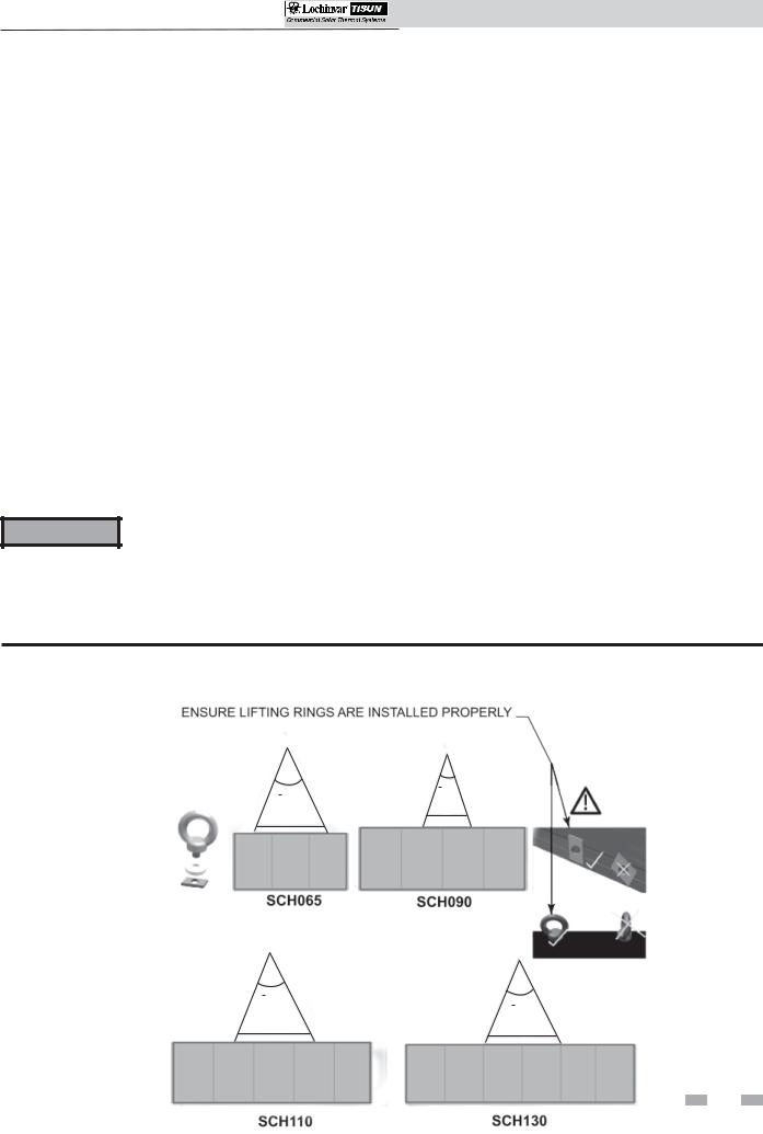
What to avoid
CAUTION |
• Collectors are to be located such that |
|
|
eventual sliding of snow and ice does |
|
|
not endanger any person. |
|
|
• See FIG. 2-6 for crane transportation |
|
NOTICE |
||
connection points and positioning. |
||
|
Figure 2-6 Crane Transportation Connection Points and Positioning
< 30°
< 30°
6.5 ft.
6.5 ft.
< 30°
6.5 ft.
<30°
8.5ft.
9
SCH Colllectorsrs Instalst llation & Operationti Manuall
3 Roof Attachment Installation
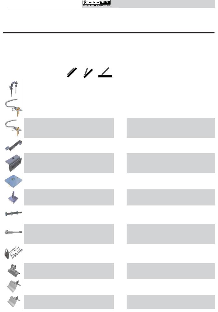
Roof attachment types
Table 3A Roof Fastenings - Parts
|
|
|
SOLAR ROOF MOUNTS |
|
Installation Type |
|
|
|
|
|
|
|
|
|
|
|
|
||||||||||||||
|
|
|
|
|
|
|
|
|
|
|
|
|
|
|
|
|
|
|
|
|
|
|
|||||||||
|
|
|
|
|
|
|
|
|
|
|
|
|
Parallel |
|
Inclined |
|
Free- |
See |
|
|
Description |
|
|
|
|
|
|
||||
|
|
|
|
|
|
|
|
|
|
|
Lochinvar |
|
|
|
|
|
|
standing |
Page |
|
|
|
|
|
|
|
|
||||
|
|
|
|
|
|
|
|
|
|
|
|
|
|
|
|
|
|
|
|
|
|
|
|
|
|
|
|
||||
|
|
|
Part # |
|
|
|
|
|
|
|
|
|
|
|
|
|
|
|
|
|
|
|
|
||||||||
|
|
|
Name |
|
|
|
|
|
|
|
|
|
|
|
|
|
|
|
|
|
|
|
|
||||||||
|
|
|
|
|
|
|
|
|
|
|
|
|
|
|
|
|
|
|
|
|
|
|
|
|
|
|
|
|
|
|
|
|
|
|
|
|
|
|
|
|
|
|
|
|
|
|
|
|
|
|
|
|
|
||||||||||
|
|
|
|
|
|
|
|
|
|
|
BOLT, |
|
|
|
|
|
|
|
|
|
Stainless steel attachment for universal heavy duty |
||||||||||
|
|
|
|
|
|
|
|
|
|
|
|
|
|
|
|
|
|
|
|
||||||||||||
|
|
|
|
|
|
|
|
|
|
|
|
X |
|
X |
|
X |
13 |
installations, |
on parallel |
and |
inclined |
roofs |
and |
||||||||
|
|
|
|
|
|
|
|
SRM20001 |
DOUBLE |
|
|
|
|||||||||||||||||||
|
|
|
|
|
|
|
|
|
|
|
freestanding |
installations |
on |
sufficiently |
anchored |
||||||||||||||||
|
|
|
|
|
|
|
|
|
|
|
HANGER |
|
|
|
|
|
|
|
|
|
|||||||||||
|
|
|
|
|
|
|
|
|
|
|
|
|
|
|
|
|
|
|
|
bases. |
|
|
|
|
|
|
|
|
|
|
|
|
|
|
|
|
|
|
|
|
|
|
|
|
|
|
|
|
|
|
|
|
|
|
|
|
|
|
|
|
|
|
|
|
|
|
|
|
|
|
|
|
|
|
|
|
|
|
|
|
|
|
|
|
|
|
|
|
|
|
|
|
|
|
|
|
|
|
|
|
|
|
|
|
|
|
ANCHOR, |
|
|
|
|
|
|
|
|
|
Stainless steel attachment |
for |
parallel |
and |
inclined |
||||||
|
|
|
|
|
|
|
|
|
|
|
|
|
|
|
|
|
|
|
|
||||||||||||
|
|
|
|
|
|
|
|
|
|
|
|
X |
|
X |
- |
15 |
installations on various types of tiled roofs. Standard |
||||||||||||||
|
|
|
|
|
|
|
|
SRM20003 |
RAFTER, STD |
|
|
||||||||||||||||||||
|
|
|
|
|
|
|
|
|
|
installations for tile heights of up to 1.5". Package is |
|||||||||||||||||||||
|
|
|
|
|
|
|
|
|
|
|
ROOF TILE |
|
|
|
|
|
|
|
|||||||||||||
|
|
|
|
|
|
|
|
|
|
|
|
|
|
|
|
|
|
|
|
complete with fasteners and spacers. |
|
|
|
|
|||||||
|
|
|
|
|
|
|
|
|
|
|
|
|
|
|
|
|
|
|
|
|
|
|
|
|
|||||||
|
|
|
|
|
|
|
|
|
|
|
|
|
|
|
|
|
|
|
|
|
|
|
|
|
|
|
|
|
|
|
|
|
|
|
|
|
|
|
|
|
|
|
ANCHOR, |
|
|
|
|
|
|
|
|
|
Stainless steel attachment |
for |
parallel |
and |
inclined |
||||||
|
|
|
|
|
|
|
|
|
|
|
|
|
|
|
|
|
|
|
|
||||||||||||
|
|
|
|
|
|
|
|
|
|
|
|
X |
|
X |
- |
15 |
installations on various types of tiled roofs. Standard |
||||||||||||||
|
|
|
|
|
|
|
|
SRM20004 |
RAFTER, TALL |
|
|
||||||||||||||||||||
|
|
|
|
|
|
|
|
|
|
installations for tile heights of up to 2". Package is |
|||||||||||||||||||||
|
|
|
|
|
|
|
|
|
|
|
ROOF TILE |
|
|
|
|
|
|
|
|||||||||||||
|
|
|
|
|
|
|
|
|
|
|
|
|
|
|
|
|
|
|
|
complete with fasteners and spacers. |
|
|
|
|
|||||||
|
|
|
|
|
|
|
|
|
|
|
|
|
|
|
|
|
|
|
|
|
|
|
|
|
|||||||
|
|
|
|
|
|
|
|
|
|
|
|
|
|
|
|
|
|
|
|
|
|
|
|
|
|
|
|
|
|
|
|
|
|
|
|
|
|
|
|
|
|
|
HOOK, FLAT |
|
|
|
- |
|
- |
|
Stainless steel attachment for parallel installations on |
||||||||||||
|
|
|
|
|
|
|
|
|
|
|
|
|
|
|
|
||||||||||||||||
|
|
|
|
|
|
|
|
SRM20005 |
|
X |
|
16 |
plain tile, slate, and flat cement tiled roofs with pitches |
||||||||||||||||||
|
|
|
|
|
|
|
|
TILE |
|
|
|||||||||||||||||||||
|
|
|
|
|
|
|
|
|
|
|
|
|
|
|
|
|
|
|
|
|
in excess of 30 degrees. |
|
|
|
|
|
|
|
|
||
|
|
|
|
|
|
|
|
|
|
|
|
|
|
|
|
|
|
|
|
|
|
|
|
|
|
|
|
|
|
|
|
|
|
|
|
|
|
|
|
|
|
|
|
|
|
|
|
|
|
|
|
|
Stainless steel attachment for parallel and inclined |
||||||||||
|
|
|
|
|
|
|
|
|
|
|
|
|
|
|
|
|
|
|
|
|
|||||||||||
|
|
|
|
|
|
|
|
SRM20006 |
CLAMP, JOINT |
|
X |
|
X |
- |
18 |
installations |
on jointed tin, galvanized, or |
copper |
|||||||||||||
|
|
|
|
|
|
|
|
|
|
roofs. Additional securing |
cables |
(Lochinvar |
Part # |
||||||||||||||||||
|
|
|
|
|
|
|
|
|
|
|
|
|
|
|
|
|
|
|
|
|
SRM20012) are required for inclined installations. |
||||||||||
|
|
|
|
|
|
|
|
|
|
|
|
|
|
|
|
|
|
|
|
|
|
|
|
|
|
|
|
|
|
|
|
|
|
|
|
|
|
|
|
|
|
|
PLATE, |
|
|
|
|
|
|
|
|
|
Galvanized steel attachment for parallel, inclined and |
||||||||||
|
|
|
|
|
|
|
|
|
|
|
|
|
|
|
|
|
|
|
|
||||||||||||
|
|
|
|
|
|
|
|
SRM20007 |
FLANGE, |
|
X |
|
X |
|
X |
20 |
freestanding installations on asphalt or elastomer |
||||||||||||||
|
|
|
|
|
|
|
|
|
|
|
SHINGLE, STD. |
|
|
|
|
|
|
|
|
|
roofs. |
|
|
|
|
|
|
|
|
|
|
|
|
|
|
|
|
|
|
|
|
|
|
|
|
|
|
|
|
|
|
|
|
|
|
|
|
|
|
|
|
|
|
|
|
|
|
|
|
|
|
|
|
|
PLATE, |
|
|
|
|
|
|
|
|
|
Galvanized |
steel |
attachment |
for inclined |
and |
||||||
|
|
|
|
|
|
|
|
|
|
|
|
|
|
|
|
|
|
|
|
||||||||||||
|
|
|
|
|
|
|
|
|
|
|
FLANGE, |
- |
|
|
|
|
|
|
|
||||||||||||
|
|
|
|
|
|
|
|
SRM20008 |
|
|
X |
|
X |
22 |
freestanding installations on asphalt or elastomer |
||||||||||||||||
|
|
|
|
|
|
|
|
SHINGLE, |
|
|
|
||||||||||||||||||||
|
|
|
|
|
|
|
|
|
|
|
RAISED |
|
|
|
|
|
|
|
|
|
roofs. Also recommended for flat roofs. |
|
|
|
|
||||||
|
|
|
|
|
|
|
|
|
|
|
|
|
|
|
|
|
|
|
|
|
|
|
|
|
|
|
|
|
|
|
|
|
|
|
|
|
|
|
|
|
|
|
BOLT, |
|
|
|
|
|
|
|
|
|
Galvanizedsteelattachmentforinclinedorfreestanding |
||||||||||
|
|
|
|
|
|
|
|
|
|
|
|
|
|
|
|
|
|
|
|
||||||||||||
|
|
|
|
|
|
|
|
|
|
|
ANCHOR, |
- |
|
|
|
|
|
|
|
||||||||||||
|
|
|
|
|
|
|
|
SRM20009 |
|
|
X |
|
X |
26 |
installations with 2.75" height adjustment. For use in |
||||||||||||||||
|
|
|
|
|
|
|
|
CONCRETE W/ |
|
|
|
||||||||||||||||||||
|
|
|
|
|
|
|
|
|
|
|
ADJ |
|
|
|
|
|
|
|
|
|
applications with no more than a 5 degree inclination. |
||||||||||
|
|
|
|
|
|
|
|
|
|
|
|
|
|
|
|
|
|
|
|
|
|
|
|
|
|
|
|
|
|
|
|
|
|
|
|
|
|
|
|
|
|
|
|
|
|
|
|
|
|
|
|
|
|
|
|
|
|
|
|
||||
|
|
|
|
|
|
|
|
|
|
|
BOLT, |
|
|
|
|
|
|
|
|
|
Galvanized |
steel |
attachment |
|
for |
inclined |
or |
||||
|
|
|
|
|
|
|
|
|
|
|
|
|
|
|
|
|
|
|
|
|
|||||||||||
|
|
|
|
|
|
|
|
|
|
|
- |
|
|
X |
|
X |
26 |
freestanding installations with no height adjustment. |
|||||||||||||
|
|
|
|
|
|
|
|
SRM20010 |
ANCHOR, |
|
|
|
|||||||||||||||||||
|
|
|
|
|
|
|
|
|
|
|
For use in applications with no more than a 5 degree |
||||||||||||||||||||
|
|
|
|
|
|
|
|
|
|
|
CONCRETE |
|
|
|
|
|
|
|
|||||||||||||
|
|
|
|
|
|
|
|
|
|
|
|
|
|
|
|
|
|
|
|
inclination. |
|
|
|
|
|
|
|
|
|
|
|
|
|
|
|
|
|
|
|
|
|
|
|
|
|
|
|
|
|
|
|
|
|
|
|
|
|
|
|
|
|
|
|
|
|
|
|
|
|
|
|
|
|
|
|
|
|
|
|
|
|
|
|
|
|
|
|||||||||
|
|
|
|
|
|
|
|
|
|
|
KIT, UNIV |
|
|
|
|
|
|
|
|
|
Stainless steel cable set for securing |
collectors on |
|||||||||
|
|
|
|
|
|
|
|
|
|
|
|
|
|
|
|
|
|
|
|
||||||||||||
|
|
|
|
|
|
|
|
|
|
|
- |
|
|
X |
- |
19 |
inclined jointed roofs. Kit includes |
|
cable, turnbuckle, |
||||||||||||
|
|
|
|
|
|
|
|
SRM20012 |
CABLE |
|
|
|
|||||||||||||||||||
|
|
|
|
|
|
|
|
|
|
hardware for attachment to frame, and joint clamp. |
|||||||||||||||||||||
|
|
|
|
|
|
|
|
|
|
|
SECURING |
|
|
|
|
|
|||||||||||||||
|
|
|
|
|
|
|
|
|
|
|
|
|
|
|
|
|
|
|
|
For inclined installations only. |
|
|
|
|
|
|
|
||||
|
|
|
|
|
|
|
|
|
|
|
|
|
|
|
|
|
|
|
|
|
|
|
|
|
|
|
|
||||
|
|
|
|
|
|
|
|
|
|
|
ATTACHMENT, |
|
X |
|
X |
- |
23 |
Stainless steel attachment for parallel and inclined |
|||||||||||||
|
|
|
|
|
|
|
|
|
|
|
|
|
|||||||||||||||||||
|
|
|
|
|
|
|
|
SRM20013 |
ROOF CORR |
|
|
||||||||||||||||||||
|
|
|
|
|
|
|
|
|
|
installations on profiled and corrugated roofs. |
|
|
|||||||||||||||||||
|
|
|
|
|
|
|
|
|
|
|
METAL |
|
|
|
|
|
|
|
|
|
|||||||||||
|
|
|
|
|
|
|
|
|
|
|
|
|
|
|
|
|
|
|
|
|
|
|
|
|
|
|
|
|
|
|
|
|
|
|
|
|
|
|
|
|
|
|
|
|
|
|
|
|
|
|
|
|
|
|
|
|
|
|
|
|
|
|
|
|
|
|
|
|
|
|
|
|
|
|
ATTACHMENT, |
|
|
|
|
|
|
- |
|
Galvanized |
steel |
attachment |
for |
installations |
on |
||||||
|
|
|
|
|
|
|
|
|
|
|
|
|
|
|
|
|
|
||||||||||||||
|
|
|
|
|
|
|
|
SRM20014 |
WAVE ROOF |
|
X |
|
X |
25 |
concrete corrugated roofs with 5 corrugations per |
||||||||||||||||
|
|
|
|
|
|
|
|
|
|
|
SM |
|
|
|
|
|
|
|
|
|
meter. For parallel and inclined installations. |
|
|
||||||||
|
|
|
|
|
|
|
|
|
|
|
|
|
|
|
|
|
|
|
|
|
|
|
|
|
|
|
|
|
|
|
|
|
|
|
|
|
|
|
|
|
|
|
ATTACHMENT, |
|
|
|
|
|
|
- |
|
Galvanized |
steel |
attachment |
for |
installations |
on |
||||||
|
|
|
|
10 |
SRM20015 |
WAVE ROOF |
|
X |
|
X |
25 |
concrete corrugated roofs with 8 corrugations per |
|||||||||||||||||||
|
|
|
|
|
|
LG |
|
|
|
|
|
|
|
|
|
meter. For parallel and inclined installations. |
|
|
|||||||||||||
|
|
|
|
|
|
|
|
|
|
|
|
|
|
|
|
||||||||||||||||
|
|
|
|
|
|
|
|
|
|
|
|
|
|
|
|
|
|
|
|
|
|
|
|
|
|
|
|
|
|
|
|
 10
10 
SCH Collectors Installation & Operation Manual
3 Roof Attachment Installation (continued)
Roof attachment quantities for SCH collectors snow loading
Table 3B Parallel Installations
|
|
SRM: 20001, 20003, 20004, 20006, 20007, |
SRM: 20005 |
||
installation |
|
20013, 20014, 20015 |
|||
|
|
|
|||
|
|
|
|
|
|
|
area load up to |
area load up to |
area load up to |
area load up to |
|
|
|
||||
|
|
32 lb/sq-ft |
64 lb/sq-ft |
16 lb/sq-ft |
32 lb/sq-ft |
|
|
|
|
|
|
Parallel |
SCH065 |
6 |
10 |
6 |
10 |
|
|
|
|
|
|
SCH110 |
8 |
14 |
8 |
14 |
|
|
SCH090 |
8 |
12 |
8 |
12 |
|
|
|
|
|
|
|
SCH130 |
10 |
18 |
10 |
18 |
|
|
|
|
|
|
Table 3C Inclined (20°, 40°, and 60°) Installations
60°) |
|
SRM: 20001, 20003, 20004, 20007, 20008, |
SRM: 20006 |
+ 20012 |
|
|
20009, 20010, 20013, 20014, 20015 |
||||
|
|
|
|||
|
|
|
|
||
Inclined(20, 40°, installation |
|
|
|
|
|
SCH110 |
8 |
14 |
18 |
3 |
|
|
|
area load up to 32 lb/ |
area load up to 64 lb/ |
area load up to 64 lb/sq-ft |
|
|
|
sq-ft |
sq-ft |
|
|
|
SCH065 |
6 |
10 |
12 |
2 |
|
SCH090 |
8 |
12 |
14 |
3 |
|
|
|
|
|
|
|
SCH130 |
10 |
18 |
22 |
4 |
 11
11 
SCH Collectors Installation & Operation Manual
3 Roof Attachment Installation
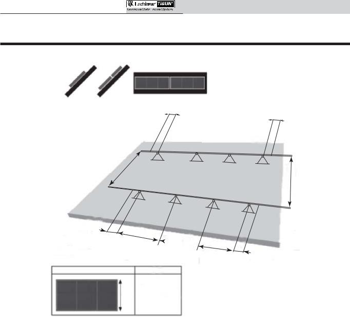
Figure 3-1 Spacing Distance
a
a
=
a
=
=  =
=
a = 2 - 10 in.
x
a
X
55 - 63 in.
Spacing Distance
Equally space the center roof attachments starting in the middle, the two (2) end attachments will be spaced according to the inner measurement (start in the middle and work outwards). The remaining roof mounts should be equally spaced in between the two (2) end roof attachments.
Note: For multiple collector installations reference the Collector Mounting Section of this manual for spacing between collectors.
Each collector will have its own independent substructure set. Ensure there is ample room on the chosen roof area for the number of collectors chosen.
 12
12 
SCH Collectors Installation & Operation Manual
3 Roof Attachment Installation (continued)
Installation of roof attachment types
The solar thermal collectors are capable of being mounted to several different types of roofing with a wide variety of mounting hardware available from Lochinvar.
Double hanger bolt for universal fastening #SRM20001
Universal fixture for parallel and inclined installation on various roof types and freestanding installation on sufficiently anchored frames. Two hanger bolts are to be installed on the roof as vertically as possible with a spacing of 4 3/4" to 6 3/4". The two are connected by an intermediate plate.
CAUTION |
• |
The hanger bolt must be screwed |
|
|
into a support capable of bearing |
|
|
the required static load (generally |
|
|
rafters). |
|
• |
Install the hanger bolt using a field |
|
|
supplied anchoring adapter. |
|
• |
The roofing must be capable of |
|
|
withstanding the pressure needed |
|
|
to compress the gasket. |
|
• |
Beware of linear expansion in sheet |
|
|
metal that prevents a linear |
|
|
expansion and can cause lifting of |
|
|
the sheet. |
Unpacking and checking parts
When unpacking the system, check the model names of the components of each system and check to be sure you have the correct number of parts (see FIG. 3-2).
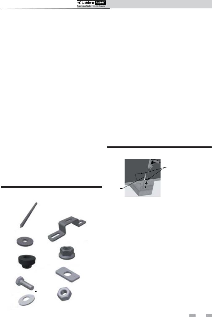
Figure 3-2 Kit #SRM20001 - Double Hanger Bolt Kit
Components
Install double hanger bolt
1.Determine roof type. Inspect the structural integrity of the roof and the durability of the roof materials.
2.Determine the number of collectors needed for the installation and the number of required roof attachments from Table 3B or 3C on page 11.
3.Determine collector connection points (spacing). Measure the spacing of the rafters or trusses to confirm the dimensions and prepare for the system layout (reference the Roof Attachment Spacing Section on page 12).
4.Pre-drill two 9mm holes, a minimum of 4 inches deep into the roof substructure (see FIG. 3-3), perpendicular to the roof with a spacing of 4 3/4" to 6 3/4".
5.Install the hanger bolts into the pre-drilled holes until the threads are level with the roof’s surface.
Figure 3-3 Pre-Drill 9mm Holes Into Substructure
PRE-DRILL TWO (2) 9MM HOLES PERPENDICULAR TO THE ROOF (APPROX. 4 IN. DEEP)
INSTALL
HANGER
BOLT(S)
HANGER BOLT (M12) (2X)
DOUBLE HANGER BOLT PLATE (1X)
WASHER (M12) (2X)
HEX NUT W/FLANGE (M12) (6X)
HANGER BOLT SEAL (2X)
SQUARE DISK (1X)
HEX BOLT (M8) (1X)
HEX NUT (M8) (1X)
WASHER (M8) (1X)
6.Slide the hanger bolt seals over the machine threads until the seal is touching the roof’s surface (FIG. 3-4A).
7.Slide the washer (M12) on top of the hanger bolt seal (FIG. 3-4A).
8.Thread the hex nut with flange (flange side down) onto the washer, compressing the washer and hanger bolt seal to the roof (FIG. 3-4B).
9.Install the second hex nut with flange (flange side up) until the hex nut reaches the desired substructure height (FIG. 3-4B).
10.Slide the hanger bolt plate onto the flange of the hex nut installed in Step 9 (FIG.’s 3-4A and 3-4B).
11.Install the remaining hex nut with flange (flange side down) to the top of the double hanger bolt plate. Tighten and secure both hex nuts (top and bottom) to the double hanger bolt plate.
12.Make certain all double hanger bolt plates are facing the same direction.
13

SCH Collectors Installation & Operation Manual
3 Roof Attachment Installation
Figure 3-4A Install Double Hanger Bolt Components |
Figure 3-5 Install Hex Bolt(s) |
|
||||||||||
|
|
|
|
|
|
|
HEX BOLT |
|
|
|
||
|
|
|
|
HEX NUT W/FLANGE |
SQUARE DISK |
|
|
|||||
|
|
|
|
|
|
|||||||
|
|
|
|
|
|
|
|
|
|
|||
|
|
|
|
|
|
HANGER BOLT PLATE |
DOUBLE HANGER |
|
|
|
|
|
|
|
|
|
|
|
|
|
|
|
|
||
|
|
|
|
|
|
HEX NUT W/FLANGE |
BOLT PLATE |
|
||||
|
|
|
|
|
|
|
||||||
|
|
|
|
|
|
WASHER (M12) |
|
|
|
|
|
|
|
|
|
|
|
|
|
|
|
|
|
||
|
|
|
|
|
|
HANGER BOLT SEAL |
|
|
|
|
|
|
|
|
|
|
|
|
|
|
|
|
|
|
|
|
|
|
|
|
|
HANGER BOLT |
|
|
|
|
|
|
|
|
|
|
|
|
|
|
|
|
|
|
|
min.
4”
Figure 3-4B Compress Washer and Hanger Bolt Seal
DOUBLE HANGER BOLT PLATE
HEX NUT
FLANGE UP
NUT
WASHER
SEAL
13.Slide the square disk onto the hex bolt (see FIG. 3-5).
14.Install the hex bolt with square disk attached into the opening of the double hanger bolt plate as shown in FIG. 3-5.
Note: Do not tighten hex bolts until ready to install on the collector substructure.
15.Thread the hex nut (M8) and washer (M8) onto the bottom of the hex bolt installed in Step 14 (FIG. 3-5).
16.Repeat Steps 4 - 15 until installation is complete.
Install hex bolt onto collector substructure (reference Section 4 - Collector Installation)
14 
 Loading...