

Page 1

Installation & Part s Manual
MS-Series Spherical Two-Case Meters
Installation: M100-20 www.lcmeter.com
Page 2

Table of Contents
!!
!!
!
WARNING WARNING
WARNING WARNING
WARNING
• Before using this product, read and understand the instructions.
• Save these instructions for future reference.
• All work must be performed by qualified personnel trained in the proper application, installation, and
maintenance of equipment and/or systems in accordance with all applicable codes and ordinances.
• Failure to follow the instructions set forth in this publication could result in property damage, personal injury,
or death from fire and/or explosion, or other hazards that may be associated with this type of equipment.
Description Page Number
Safety Precautions ..............................................3
How LC Meters Work ..........................................4
Owner’s Information Packet ................................5
Installation Requirements................................... 6
System Design Considerations .......................... 7-10
Operation Requirements .................................... 11
Meter Start Up and Operation ............................ 12-14
Reversing the Meter Registration .......... 13
Setting the Standard Adjuster................ 14
Meter Maintenance ............................................ 15-16
Servicing the Drive Components........................ 17-20
Removing the Dust Cover ..................... 17
Removing the Adjuster
& Adjuster Driver Assembly ................... 17-19
Servicing the Packing Gland ................. 19
Packing Gland Components.................. 20
The Retaining Plate............................... 20
Disassembling the Meter.................................... 21-26
Draining Fluid from the Meter................ 21
Opening the Weldment Assembly ......... 21-22
Removing Rotor Gears.......................... 22-24
Removing the Bearing Plate & Rotors... 24-25
Removing Meter Housing Assembly...... 25
Universal Joint Assembly ...................... 26
Reassembling the Meter .................................... 27-30
Installing the Meter ................................ 27
Assembling the Meter............................ 27-28
Rotor Gear Timing................................. 29
Reassembling Weldment Assembly ...... 30
Bolt Tightening Sequence .................................. 31
Wrench and Socket Size Chart .......................... 31
Fastener and Torque Chart ................................ 32
Identification of Bolt Grades ............................... 33
Troubleshooting.................................................. 33-34
How to Order Replacement Parts ...................... 35
Parts Breakdown ................................................ 36-39
Publication Updates and Translations
The most current English versions of all Liquid Controls publications are available on our website, www.lcmeter.com.
It is the responsibility of the Local Distributor to provide the most current version of LC Manuals, Instructions, and
S pecification Sheets in the required language of the country, or the language of the end user to which the products are
shipping . If there are questions about the language of any LC Manuals, Instructions, or Specification Sheets, please
contact your Local Distributor.
Please have the following information available when making inquiries, ordering replacement parts, or
scheduling service. If a specific meter accessory is involved, please provide the model and serial number
of the meter in question (see page 5).
Meter Serial Number ________________________________________
Full Service Distributor ________________________________________
Full Service Distributor Phone Number ________________________________________
2
Page 3

Safety Precautions
All internal pressures must be relieved before disassembly of the meter , strainer, vapor eliminator ,
any valves in the system, the pulse output device, or the front and rear covers. LINE PRESSURE
MUST BE 0.0 PSI. See “Meter Maintenance” on Page 15 for the procedures to relieve internal
!!
!!
!
WARNING WARNING
WARNING WARNING
WARNING
NOTICE:
This manual provides warnings and procedures that are
intended to inform the owner/operator of the hazards
present when using the Liquid Controls Meter on LPG
and other products. The reading of these warnings and
the avoidance of such hazards is strictly in the hands of
the owner/operator of the equipment. Neglect of that
responsibility is not within the control of the manufacturer
of the meter.
SAFETY PROCEDURES:
Remember to relieve internal pressure before
disassembly or inspection of the strainer, vapor eliminator ,
valves, POD pulser, and the front or rear covers. See
“Meter Maintenance” on Page 15 for the steps to relieve
internal pressure in your system.
BE PREPARED:
• Make sure that all necessary safety precautions have
been taken. Provide for proper ventilation,
temperature control, fire prevention, evacuation, and
fire management.
• Provide easy access to the appropriate fire
extinguishers for your product. Consult with your local
fire department, state, and local codes to make sure
that you are adequately prepared.
• Read this manual as well as all the literature provided
in your “Owner’s Information Packet”. If you have
any questions, consult your full-service distributor or
call the Service Department at Liquid Controls.
IN THE EVENT OF A GAS LEAK:
In the event of a large gas leak:
Evacuate the area and notify the fire department.
In the event of a small, contained gas leak:
1. Stop the leak.
2. Prevent accidental ignition.
3. Prevent entrance of gas into other portions of the
building. Some gases, such as LPG, seek lower
levels, while other gases seek higher levels.
4. Evacuate all people from the danger zone.
5. See that the gas is dispersed before resuming
business and operating motors. If in doubt, notify your
local fire department.
IN THE EVENT OF A GAS FIRE:
In the event of large fires or fires that are spreading:
1. Evacuate the building and notify your local fire
department.
2. S top the leakage only if the equipment can safely be
reached.
In the event of small, contained fires that you can safely
control:
1. S top the leakage only if the equipment can safely be
reached.
2. Use the appropriate extinguisher: Class B fire
extinguisher, water, fog, etc., depending on the
materials. If in doubt, call your local fire department.
3
Page 4
How LC Meters Work
Liquid Controls MS-Series meters are positive
displacement flowmeters. They are designed for liquid
measurement in both custody transfer and process
control applications. Because of their simple design, they
are easy to maintain, and can easily be adapted to a
variety of systems.
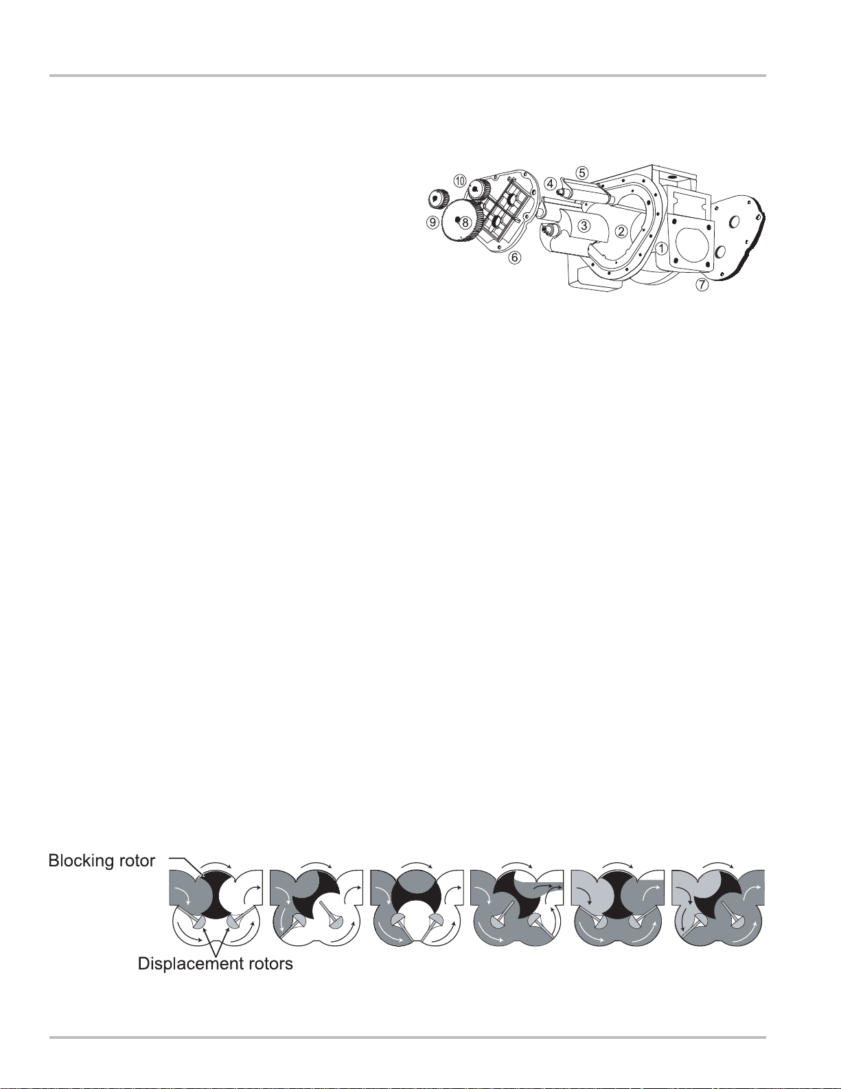
The meter element (1) is designed with three cylindrical
bores (2). A Blocking rotor (3) and two Displacement
rotors (4,5) turn in a synchronized relationship within the
bores. The three rotors are supported by bearing plates
(6,7). The ends of the rotors protrude through the bearing
plates. Blocking rotor gear (8) is placed on the end of
the blocking rotor (3). Displacement rotor gears (9,10)
are placed on the ends of the displacement rotors (4,5).
These gears create the synchronized timed relationship
between the three rotors.
Capillary seals mean no metal-to-metal contact within
the metering element. This means no wear. No wear
means no increase in slippage, and no increase in
slippage means no deterioration in accuracy.
As fluid moves through the meter element, the rotor
assembly turns. The liquid is segmented into uniform
sections by the turning rotors. Fluid displacement
happens simultaneously . As fluid enters, another portion
of the fluid is being partitioned and measured. At the
same time, the fluid ahead of it is being displaced out of
the meter and into the discharge line. Since the volume
of the bores is known, and the same amount of fluid
passes through the meter during each revolution of the
blocking rotor, the exact volume of liquid that has p assed
through the meter can be determined.
This true rotary motion is transmitted through either the
pulse output device (POD) to the encoder, or the face
gear and drive shaft to the counter/register. True rotary
motion output means consistent accuracy since the
register indication is in precise agreement with the actual
volume throughput at any given instant.
At any position in the cycle, the meter body, the blocking
rotor, and at least one of the displacement rotors form a
continuous capillary seal between the un-metered
upstream product and the metered downstream product.
Throughout the metering element, the mating surfaces
are either flat surfaces or cylindrical faces and sections
that are accurately machined. These relatively simple
machining operations, plus the fact that there is no
oscillating or reciprocating motion within the device,
permit extremely close and consistent tolerances within
the LC meter.
The product flowing through the meter exerts a dynamic
force that is at right angles to the faces of the
displacement rotors. The meter is designed so that the
rotor shafts are always in a horizontal plane. These two
facts result in no axial thrust. Therefore, with no need
for thrust washers or thrust bearings, the rotors
automatically seek the center of the stream between the
two bearing plates eliminating wear between the ends of
the rotors and the bearing plates.
Liquid Controls meters are made of a variety of materials
to suit a variety of products. Because of our no-wear
design, capillary seals, and unique rotary metering, LC
meters provide unequalled accuracy, long operating life,
and unusual dependability.
4
Page 5
Owner ’s Information Packet
Is all the documentation included with the meter? LC
meters come in many variations. The information sent
depends on the accessories ordered with the meter.
Make an inventory of the “Owner’s Information Packet”.
First, find the LC packing slip with the computer printout.
Locate the serial number and the meter model number
on this printout. Cross-reference the packing slip with
the actual meter serial numbers.
Included in the “Owner’s Information Packet” are the
following:
• Installation, Operation & Parts Manuals (for all
elements supplied such as LectroCount Register,
Valves, Air Eliminators, etc.)
• Bill of Materials
Record the meter serial number in the space provided
on Page 2 of this manual. This page also provides a
space for the full-service distributor’s name and telephone
number, if applicable. Fill in this information and keep it
handy. The meter serial number and model number will
be required when calling for service or parts. See “How
to Order Replacement Parts” on Page 35 in this manual.
Serial Plates
5
Page 6

Installation Requirements
!!
!!
! WARNING
All internal pressures must be relieved before disassembly of the meter, strainer , vapor eliminator ,
any valves in the system, the pulse output device, or the front and rear covers. LINE PRESSURE
MUST BE 0.0 PSI. See “Meter Maintenance” on Page 15 for the procedures to relieve internal
pressure.
• Make sure that all necessary safety precautions have
been taken. Provide for proper ventilation,
temperature control, fire prevention, evacuation, and
fire management.
• Provide easy access to the appropriate fire
extinguishers for the product. Consult with the local
fire department and state and local codes to make
sure that you are adequately prepared.
• Read this manual as well as the literature provided
in the “Owner’s Information Packet”. If there are any
questions, consult with the full-service distributor or
call the Service Department at Liquid Controls.
• Install the meter and accessories in conformance with
all applicable federal, state, local, construction,
electrical, and safety codes.
• Class 10 meters for LPG must be installed in
accordance with the requirements of ANSI-NFPA 58
in addition to all other state and local codes.
• Before shipment, protective thread caps were placed
in all meter and accessory openings. They should
remain in place until ready to attach piping.
• Prior to meter installation, the entire piping system
should be thoroughly flushed of all debris, with a liquid
that is compatible with the construction of the meter.
• Keep all external surfaces of the meter clean.
• The meter must always be securely bolted to a
platform or supporting member, regardless of the
mounting position of the meter. Never “hang” a
meter on the connecting pipe.
• Prevent pipe strain or stress from occurring when
making meter or accessory repairs. Pipe strain and
stress occur when the pipes are not supported or
are not aligned correctly to the meter. The weight of
the pipes must always be supported independent
of the meter. This means that the meter and
accessories can easily be removed without affecting
the pipes or the pipe alignment. Never leave any of
the pipes hanging.
• Apply pipe compound to male threads only.
• Install the meter down stream of the pump.
• Position the meter with service in mind. Provide
ample work space. Removing covers can be difficult
when work space is not available. Always supply a
platform or support for the meter mounting.
• A meter is metallurgically designed to be physically
compatible with a given type of liquid, as originally
specified by the customer, and as indicated on the
Serial Number Plate. A meter should not be used
with a liquid different from the liquid originally
specified, unless the physical characteristics and pH
rating are similar and the application has been
checked with Liquid Controls Sales or Engineering.
NOTE: Always request up-to-date, engineering approved, dimensional drawings before starting any construc-
tion. Do not rely on catalog pictures or drawings which are for reference only. After receiving prints,
check to see that all equipment ordered is shown and that any extra pressure taps, plugs, etc. are
noted and their size specified.
6
Page 7

System Design Considerations
Flowmeters must be installed properly if accuracy and
repeatability of measurements are to be sustained over
long periods of time. The system in which the meters
are to be used must have provisions for controlling flow,
transitional, and no flow conditions. Pressure, both
hydrostatic and hydrodynamic, must be an integral part
of the variables controlled in the flowing system. Systems
in which meters are to be installed must be designed to
eliminate transient pressure conditions, eliminate
thermally induced pressure increases, and to exclude
air or vapor.
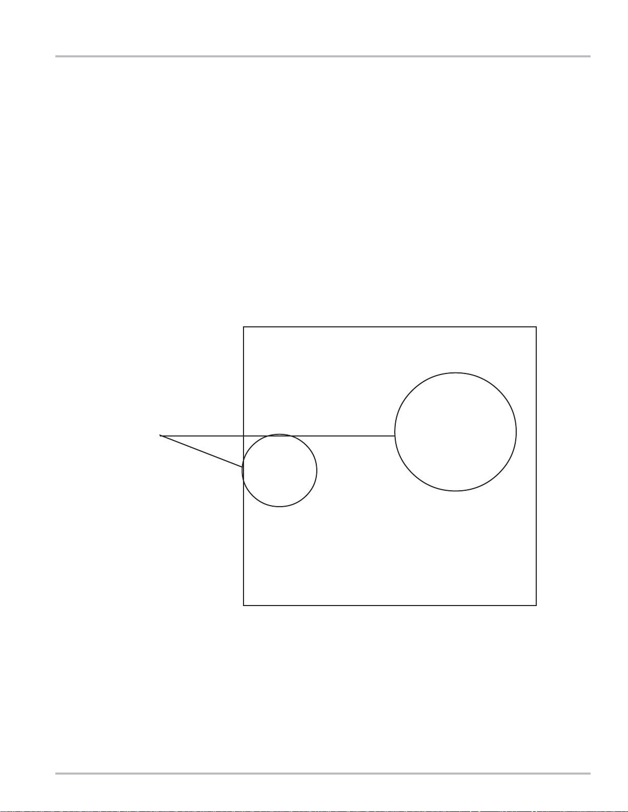
The complete system must be kept full of product at all
times. The photograph below is a typical fuel delivery
gantry designed for loading rail tank wagons. This
particular gantry has provisions for loading 152 rail tank
wagons at one time. Four different fuels are supplied to
the gantry through 16 inch pipe lines which are
approximately ½ mile long. The pumps are centrifugal
type and are located between 100 and 300 yards from
the storage tanks.
The next photograph shows a typical gantry position.
From left to right, there is a supply line attached to an
isolation valve, a second isolation valve and piping
leading vertically to the loading arm. The meter is
equipped with a dual channel, quadrature pulse
Strainer/Air
Eliminator
Supply Side
Isolation Valve
transmitter connected directly to a batch controller. The
batch controller provides preset batch capability, flow rate
control, and slow flow start and stop. There is one batch
controller for each metering position.
MS Series Meter
Outlet Side
Isolation Valve
Pulse Output
Device (POD)
7
Page 8

System Design Considerations
Design For Calibration
Field calibration of meters is essential. Calibration
conducted during meter production is to confirm the meter
is capable of attaining the required accuracy/linearity and
repeatability.
Typically, the meter characteristics are:
Mechanical Registration
• Repeatability: Capable of .02% or better at any flow
rate over entire range
• Linearity: ± .125% over a 5:1 range
• Linearity: ± .22% over a 10:1 range
• Linearity: ± .5% over a 40:1 range
Electronic Registration
• Repeatability: Capable of .02% or better at any flow
rate over entire range
• Linearity: ± .1% over a 5:1 range
• Linearity: ± .1% over a 10:1 range
• Linearity: ± .15% over a 40:1 range
The meters are normally tested against a master meter
that has been proven against a Weights & Measures
certified, volumetric prover.
The pictures below show a properly configured meter
installation and mobile master prover. The prover
connections are at the right. The two valves to the left of
the meter are for connecting the volumetric prover or
Volumetric Prover
master meter to be used for calibration. The valve
mounted in the vertical line between the two horizontally
mounted valves is a double-block, bleed valve used to
ensure there is no leakage through the valve during
calibration.
Proper Meter Installation
Mobile Master Proving Trolley
8
Page 9
System Design Considerations
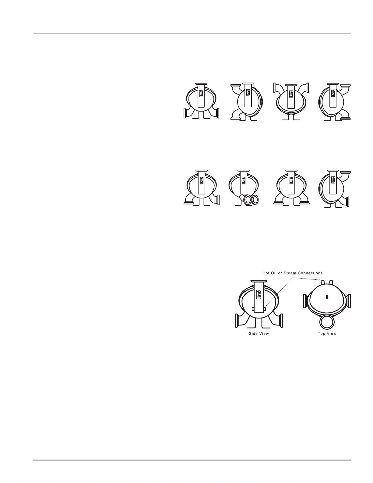
Design for Standard Mounting Arrangements
(straight through flow)
Regardless of meter mounting configuration,
accessories such as the air/vapor eliminator must
always be mounted in a vertical orientation to permit
proper operation of the float-actuated apparatus.
Design for Special Mounting Arrangements
Special flange arrangements are available as shown.
Contact the factory for details or additional information.
Design for Hot Oil/Steam Jacket Options
Heating a meter can be accomplished by hot oil/steam
jacketing the meter’s rear cover and/or packing gland
boss. A heat jacketed meter does not preclude the
necessity for insulating the meter and surrounding piping.
Design for Ensuring the System Remains Full of Product
The first consideration is merely filling the piping for the
first time. The filling of the system must take place slowly
in order to avoid pressure “spikes” or transients caused
by rapid acceleration or deceleration of the liquid. Under
gravity flow conditions, pressure transients in orders of
magnitude larger than the available head pressure are
possible.
At this time, air must be removed from the system. Make
sure that a positive head condition is always present in
the system (which should be designed into the system).
Air or vapor in the system contributes to error in
measurements while metering. Once air is removed from
the system, ensure that the system design does not allow
for air to re-enter the system once it is full of product.
9
Page 10

System Design Considerations
Design for Thermal Shock or
Expansion
T emperature considerations in system design should not
be ignored. Care must be taken in the design so that
zones are not created where fluid can be trapped or
locked between two closed valves. For every 1°F
increase in temperature, pressure in the trapped zone
will increase by an amount depending on the product in
the system (70 psi for LPG). A few degrees increase in
ambient temperature may create a serious problem if
thermal expansion pressure relief is not included in
regions where the product may be trapped. Typically,
the pressure setting in a thermal relief valve is set
approximately 10% higher than the nominal operating
pressure.
Design for Proper Flow Control
The example on Page 7 shows 152 meters monitoring
the delivery of 4 different products. Thirty eight meters
are used for delivery of HSD. Assume that one (1) pump
is selected to supply product to the meters. Each meter
measures 375 gallons per minute (GPM). The total flow
capacity of the pump must be:
38 X 375 GPM or 14,250 GPM.
Commissioning
Once the metering system is installed, it is ready for
commissioning. Filling the system the first time requires
care and time. Ensure that the isolation valve on the
inlet side of the meter is closed. Pressure the header by
starting the pump. At the meter position to be
commissioned, “crack” or slightly open the inlet isolation
valve until flow into the meter can be heard. Allow the
inlet side to remain in this slightly opened position until
flow stops.
At this time, “crack” or loosen the pipe plug on top of the
meter case to allow air to bleed out. Once the air is
eliminated and product is present, fully tighten the plug.
Open the inlet side isolation valve completely. The
system must be kept full of fluid to avoid damage to the
meter. If air is allowed inside the metering element,
significant damage can occur as this air expands or
compresses due to system flow and pressure conditions.
In extreme cases, the presence of air can cause
catastrophic failure of the measuring element as a result
of liquid velocities and transient pressure spikes that can
bend or break critical measuring elements. The rate at
which the system is filled and pressurized must be
controlled to eliminate the possibility of creating any
pressure transients from excessive liquid velocity . Once
the meter and system are filled, pressurized, and free of
air, flow may begin.
Once the system is in operation, product flows through
the first meter when the control valve is opened. If the
flow rate is not regulated, 14,250 GPM attempts to flow
through the meter. The resulting overspeed will
immediately damage the meter. It is critically important
that a each meter location be equipped with a digital or
hydraulic flow rate controller. These valves must be
downstream of the meter to ensure that the meter remains
full of product at all times.
Control must also be used when beginning or stopping
flow. Proper control will minimize or eliminate transient
pressure conditions brought on by rapid velocity changes
in the system.
Care must be taken during the initial flow condition to
prevent damage to the meter or strainer due to foreign
debris in the piping system. Foreign particles not removed
during flushing and hydrotesting will collect in the strainer
basket. Monitor the strainer differential pressure for the
first month of operation. Clean the strainer basket if
needed. Examine the strainer basket carefully and
replace if damaged.
Assure that the thermal relief valves are installed and
functioning properly.
10
Page 11

Operation Requirements
!!
!!
! WARNING
Under normal operation, do not expose any portion of the LP-Gas system to pressures in excess
of rated working pressures without an automatic safety valve to vent the over pressure discharge
to a place of safety away from the operator and other people. Failure to provide such a safety
relief may result in leakage or rupture of one or more of the components in the system. This can
result in injury or death from the gas, a fire, or pieces of flying debris from the rupture.
When a Back Check V alve is used, an automatic safety valve must be installed to prevent pressure
buildup (thermal expansion) in excess of rated working pressure in the meter housing. One
automatic safety valve should be installed in each meter. Remove the pipe plug from the front
cover or rear cover and insert the appropriate automatic safety valve.
The meter must remain full of product at all times.
An easy way to accomplish this is to put the meter
assembly in the line below the piping center-line (a sump
position). This requires adding elbows and flanges prior
to installing the meter. The meter should be inst alled with
a bypass loop, below the pipe center-line, with block
valves upstream and downstream. A block valve should
be located in the mainstream, labeled as the bypass
valve. A word of caution: any portion of pipe system
that might isolate or block flow should be provided with a
pressure relief to prevent damage from thermal
expansion. There are excellent benefits to this type of
installation. First, the meter is kept full. Second, this type
of installation allows the meter to be isolated for servicing
and calibration while continuing flow through the bypass
valve.
Upstream lines must be maintained full to prevent air
from entering the meter. If the upstream or inlet lines are
constructed in a manner which allows reverse flow, foot
valves or back checks must be installed.
NOTE: Use soft seats, not cast iron swing checks.
Every meter should be calibrated under actual service
and installation conditions per the API Manual of
Petroleum Measurement Standards:
Chapter 4: Proving Systems
Chapter 5: Metering
Chapter 6: Metering Assemblies
Chapter 11 Section 2.3: Water Calibration of Volumetric
Provers
Chapter 12 Section 2: Calculation of Petroleum
Quantities
These chapters of the API Manual of Petroleum
Measurement Standards supersede the API Standard
1101.
Provide a means of conveniently diverting liquid for
calibration purposes.
Give careful attention to your system’s pumping
equipment and piping because of their influence on
liquid being measured as it enters the meter assembly.
Systems should be made free of conditions that cause
or introduce entrained air or vapor.
Follow the manufacturer’s recommendations fully
when installing pumps. Give particular attention to
factors like: use of foot valves, pipe size to the inlet and
conformance to net positive suction head (NPSH)
conditions when suction pumping is required. Following
the manufacturer’s recommendations will minimize air
and vapor elimination problems.
For all products, it is desirable to use flooded suctions
and piping sized larger than the normal pump size.
Hydraulic shock is harmful to all components of an
operating system including valves, the meter and the
pump. In particular, meters must be afforded protection
from shock because of their need to measure with high
precision. Generally the best protection is prevention,
which can be readily accomplished by adjusting valve
closing rates in such a manner that shock does not occur .
Shock pressure and system pressure are independent
of each other.
Thermal expansion like hydraulic shock is a
phenomenon that can easily damage meters and
systems in general. Care should be taken in designing
the system to include pressure relief valves in any portion
or branch of the system that might be closed off by closure
of operating valves or block valves. Note that 1°F is
equivalent to an increase amount depending on the
product in the system (70 psi for LPG).
11
Page 12

Meter Start Up and Operation
Electronic Registration
Liquid Controls’ family of LectroCount® electronic registers provide near-perfect metering accuracy over a full
range of flow rates and deliver enhanced functions including: automated data collection (i.e., date, time, product,
delivery quantity and more), on-site ticket generation, meter linearization, electronic temperature volume
compensation, real-time communication capabilities (RF, GPS, CDPD), improved security and more.
Prior to meter start up, use extreme caution. Make
sure that:
1. The meter is properly secured
2. All connections are tight
3. All valves are in the closed position
Placing your meter in operation:
Check to determine that all fittings and flanges are tight
and liquid lines are closed.
Open the vapor line to the meter. Using vapor pressure
only, check each joint with a liquid soap solution to see
that no leaks go undetected. When all joints have been
checked, admit liquid SLOWLY to avoid operation on
vapor at speeds greater than the maximum indicated on
the serial number plate and to insure that cover cavities
do not contain vapor which can be compressed. Proper
slow filling can be done by throttling the system with a
valve at the meter OUTLET.
With the valve(s) open between the tank and the meter,
go to the valve located down stream of the meter. Open
the down stream valve slowly until the meter’s register/
counter starts to move. Do not run the meter any faster
than 25% of its maximum rated flow during start-up. Once
the product is flowing out the end of your system, the
outlet valve can be opened all the way provided that the
system is designed not to exceed the flow rate marked
on the meter.
NOTE: If the valves are not manual, consult the valve
manufacturer for slow flow start-up.
Filling the system with a pump:
Consult the pump manufacturer for proper pump priming.
Once the pump is primed with product, proceed.
NOTE: Make sure that your pump can operate against
a dead head pressure. If NOT, consult the factory for
assistance.
Never operate the meter or system when partially
filled with liquid, or with pockets of compressed air
or vapor present. If these conditions cannot be
avoided, air and vapor elimination systems may be
required. If you cannot fill the meter slowly by gravity
or by using a valve to throttle back the flow, consult
the factory.
• Do not operate the meter at a pressure exceeding
that marked on the Serial Number Plate. Under any
and all pressure producing circumstances, for
instance, thermal expansion and hydraulic shock, the
working pressure must not exceed the indicated
maximum.
• If the meter is operated at a rate greater than the
maximum recommended GPM, excessive wear and
premature failure may occur.
The meter can be calibrated for flows below minimum
ratings if the flow remains constant and varies within
narrow limits or if the product is viscous. A meter should
never be run beyond the maximum flow rate determined
for that class meter and/or liquid measured.
12
Page 13

Reversing the Meter Registration
The direction of flow is specified by the customer when
the meter is ordered. The standard direction of flow is
from left to right when facing the front of the meter . A red,
pressure sensitive label indicating the inlet is affixed to
the meter at the time of shipment.
If the meter is equipped with a strainer and/or valve, the
strainer and/or valve MUST be moved when reversing
the direction of flow through the meter. The strainer
should always be located on the inlet side of the meter .
When the meter is equipped with a valve, it is moved to
the outlet side of the meter. Some repositioning of the
valve components may be required. See the Valve
Manual in the Owner’s Information Packet.
When the meter is first installed, check the register . If the
register counts DOWN (numbers decrease) the direction
of registration must be reversed by either reversing the
position of the adjuster drive gear or by reprogramming
the direction of flow using the Lap Pad (for LectroCount
electronic registration). Consult the LectroCount
Operation Manual provided in the Owner’s Information
Packet.
Reversing the drive to the register is accomplished by
reversing the position of the adjuster drive gear relative
to the pinion gear of the packing gland.
Adjuster drive
gear engaged
from the top.
Adjuster drive
gear engaged
from the bottom.
1. See Meter Maintenance on Page 15 and “Servicing the Drive
Components” on Page 17, for instructions on removing the dust cover.
2. Remove the retaining spring screw(s) (1) with a st andard screwdriver.
3. Remove the retaining spring (2).
4. Remove the drive shaft (3) mounted with the adjuster driver gear
assembly (4, Retaining Ring) (5, Adjuster Drive Gear).
5. Remove the retaining ring (4) with a screwdriver or pliers.
6. Remove the adjuster driver gear (5) and turn it 180° so that it is upside
down from the original installed position. The bushing (7) supports the
adjuster drive gear in the lower position. The retaining ring (4) supports
the adjuster drive gear in the upper position.
7. Reassemble the parts in reverse order. Make sure that the adjuster
driver gear meshes with the packing gland’s pinion gear (6) without
being too tight. Make sure there is a little play in the gear teeth. The
retaining ring (4) should be placed in the grove provided on the drive
shaft (3) regardless of the adjuster drive gear position. The packing
gland pinion gear to adjuster drive gear ratio is either 1:1 or 2:1. In the
2:1 ration, the pinion of the packing gland is smaller in diameter.
13
Page 14
Setting the Standard Adjuster
Note: These instructions apply to meters equipped with
mechanical output accessories only. If the meter is
equipped with an electrical output assembly, refer to the
accessory manual, such as the Pulser Manual or
LectroCount Manual in your Owner’s Information Packet.
1. See Meter Maintenance on Page 15, and “Servicing
the Drive Components” on Page 17, to remove the
dust cover.
2. Check meter registration by delivering product to a
reliable, accurate prover. Perform multiple delivery
tests to verify the meter repeatability.
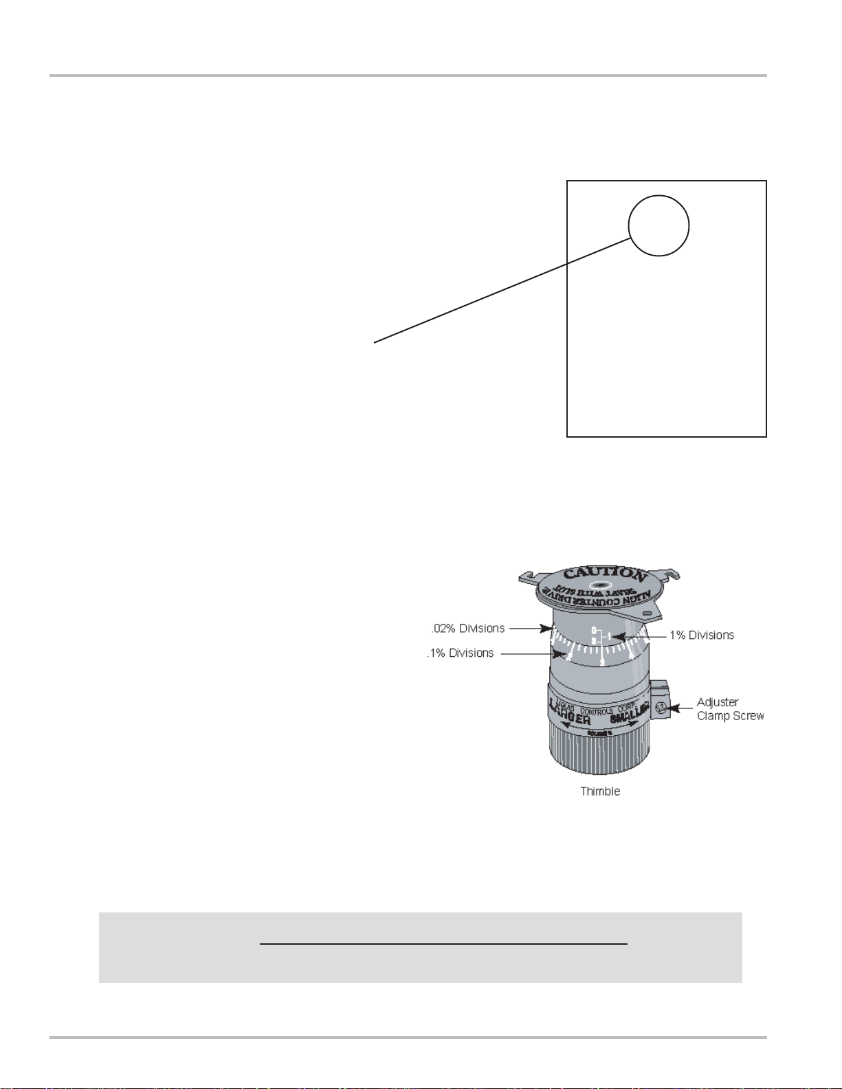
3. Record the setting indicated on the adjuster.
4. Note the volume in the prover. Calculate the
difference between the counter and prover volume.
Multiply the result by 100. Refer to the formula below .
5. Loosen the adjuster clamp screw.
6. When the prover volume is less than the meter
counter volume, add the percentage to the original
adjuster setting by turning the thimble towards the
arrow marked LARGER (volume). Correct the original
setting by approaching the number desired from the
next larger number. For example, a desired adjuster
setting is “3.4”. Turn the adjuster thimble to the lef t to
number “4”, then to the right to obtain the “3.4” setting.
7. When the prover volume is more than the meter
counter volume, subtract the percentage from the
original adjuster setting by turning the thimble in the
direction of the arrow marked SMALLER (volume).
8. Retighten the adjuster clamp screw. Run product
through the meter to allow the adjuster to take set.
Then make several prover runs to check for accuracy
and repeatability.
% CORRECTION = X 100
VOLUME IN PROVER - VOLUME ON METER COUNTER
VOLUME IN PROVER
14
Page 15

Meter Maintenance
RELIEVING INTERNAL PRESSURE
All internal pressure must be relieved to zero before disassembly or inspection of the strainers,
air eliminators, valves, the pulse output device (POD), or the front and rear covers.
Serious injury or death from fire or explosion could result from maintenance of an
improperly depressurized and evacuated system.
Procedure for Non-LPG Meters
1. Turn off pump pressure.
2. Close valves before and after the meter.
3. Remove pressure by cracking open the drain plugs until pressure is relieved. Then open the
drain plugs completely and drain the meter.
Procedure for LPG System Meters
1. Close the belly valve of the supply tank.
2. Close the valve on vapor return line.
3. Close the manual valve in the supply line on the inlet side of the meter. If no manual valve
exists on the inlet side, consult the dispenser manufacturer for procedures to depressurize
the system.
4. Slowly open the valve/nozzle at the end of the supply line.
5. After product has bled off, close the valve/nozzle at the end of the supply line.
6. Open the bleed valves located on the strainer cover and meter cover (if equipped) to relieve
pressure in the system. Product will drain from the meter system.
Caution: If the systems contains a Back Check V alve, pressure inside the meter
housing MUST be relieved by opening the bleed valve in the meter cover (if
equipped) or by loosening one of the pipe plugs in the meter cover. This
procedure must be done for each meter.
7. As product is bleeding from the bleed valve, slowly reopen and close the valve/nozzle on the
discharge line. Repeat this step until the product stops draining from the bleed valve and
discharge line valve/nozzle.
!!
!!
! WARNING
15
Page 16

Meter Maintenance
Prevent pipe strain or stress from occurring when
making meter or accessory repairs. Pipe strain and stress
occur when the pipes are not supported or are not aligned
correctly to the meter. The weight of the pipes must
always be supported independent of the meter. This
means that the meter and accessories can easily be
removed without affecting the pipes or the pipe alignment.
Never leave any of the pipes hanging.
Seasonal meter storage. If the meter is used for
seasonal work, at the end of each season the meter
should be removed from the system and thoroughly
flushed with a compatible liquid. This includes removing
the drain on the front and rear covers. Then flush the
product from the front and rear covers. If flushing with
water is preferred, extra care should be taken to drain
the meter completely and to dry all internal parts.
Immediate refilling with a compatible liquid (or oil misting)
is essential to prevent corrosion as well as ice damage
to parts from moisture that was overlooked after flushing
and drying.
Do not mar or scratch any of the precision machined
surfaces by prying or sanding parts.
Torque specifications. All fasteners such as screws and
bolts should be torqued to proper specification. See the
“Torque Chart” on Page 31 of this manual.
Removing flange seals. When removing the flange
assembly , always carefully remove the O-ring seal. Make
sure that the flange surface is clean. Discard and replace
the old O-Ring seal if it is nicked or scratched in any
way. If it is undamaged, it can be reused.
Examine all fasteners. Make sure fasteners are not
bent, rusted, or have pulled threads. The threads should
all appear evenly placed. If the bolts are bent, check the
housing and bearing plate for flatness. Use a straight
edge to determine flatness.
Look for gaps. When disassembling a meter, use a feeler
gauge to check for gaps between the bearing plate and
housing. If you do find gaps, check the bearing plates for
flatness with a straight edge. Gaps can be caused by
shock problems that must be resolved. Contact your fullservice distributor or the Service Department at Liquid
Controls for assistance if this occurs.
Check the O-Rings. O-Rings should be smooth. Cracked
or worn O-Rings should be replaced. However, a more
serious problem of shock may have occurred if the ORings look nibbled. Shock problems must be verified and
resolved. Contact your full-service distributor or the
Service Department at Liquid Controls for assistance if
this occurs.
Stone the machined surfaces when reassembling the
meter to assure that the machined surfaces are free of
burrs and mars.
Repair pulled threads with threaded insert fasteners.
These can be used in many instances. Contact your
full-service distributor for advice if this occurs.
Coating threads. When removing and replacing bolts
and castings in a meter, always coat the threads with
anti-seize.
Check the bearing plates. Check the bearing plates for
flatness. Use a straight edge. Warped bearing plates can
be caused by shock problems that must be resolved.
Contact your full-service distributor or the Service
Department at Liquid Controls for assistance if this
occurs.
Weights & Measures. Check with the regulatory agency
that governs Weights & Measures in your area. Removing
a seal wire may require Weights & Measures
recalibration.
16
Page 17

Removing the Dust Cover
1. Cut the dust cover seal wire (if present) with a side
cutters. Remove the dust cover screws with a flat
blade screwdriver. Remove the dust cover.
NOTE: See Relieving Internal Pressure and
Weights & Measures in the Meter Maintenance
section on Page 15 of this manual.
Servicing the Drive Components
Removing the Adjuster and Adjuster Drive Assembly
2. Record the Adjuster Micrometer setting.
3. Carefully note the adjuster drive gear position. The
gear engages the packing gland pinion from below
(shown) or above. The gear must be reinstalled in
its original position or the register counter will run
backwards.
17
Page 18

Servicing the Drive Components
Removing the Adjuster and Adjuster Drive Assembly (Continued)
4. Use a flat blade screwdriver to remove the two screws
of the upper retaining spring.
5. Use a flat blade screwdriver to remove the two screws
of the lower retaining spring.
6. Remove the drive assembly.
If there is a need to remove the entire counter adapter
assembly, remove the 4 screws located at the bottom
end of the assembly.
18
Page 19

Servicing the Drive Components
!!
!!
! WARNING
All internal pressures must be relieved before disassembly of the meter , strainer, vapor eliminator ,
any valves in the system, the pulse output device, or the front and rear covers. LINE PRESSURE
MUST BE 0.0 PSI. See “Meter Maintenance” on Page 15 for the procedures to relieve internal
pressure.
Removing the Adjuster and Adjuster Drive Assembly (Continued)
7. Remove the Adjuster assembly by removing the
single screw holding it in place. The adjuster can
then be rotated clockwise and removed from below.
Removing the Packing Gland
8. Remove the two packing gland retaining plate screws
with a 5/16” socket and ratchet driver extension or 5/
16” nut driver.
NOTE: It is not necessary to completely remove the
stack from the meter to service the packing gland.
9. Pull out the packing gland. There is an O-Ring for
the packing gland which may not come out with the
packing gland. If it does not come off with the packing
gland, it will be located in the packing gland well.
The packing gland may be taken apart by removing
the retaining ring from the gear end of the assembly.
19
Page 20
Servicing the Drive Components
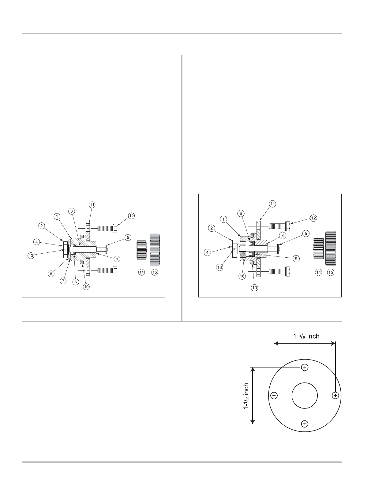
Standard Packing Gland LPG Packing Gland
1. Housing
2. Drive Blade
3. Bushing
4. Shaft
5. Retaining Clip
6. “U” Cup
7. Rulon Thrust Washer
8. Stainless Steel Thrust Washer
9. Nylon Washer
10. O-Ring
11. Retaining Plate
12. Retaining Plate Screws (2)
13. Roll Pin
14. Output Gear 1:2
15. Output Gear 1:1
1. Housing
2. Drive Blade
3. Bushing
4. Shaft
5. Retaining Clip
6. “U” Cup
9. Stainless Steel Washer
10. O-Ring
11. Retaining Plate
12. Retaining Plate Screws (2)
13. Roll Pin
14. Output Gear 1:2
15. Output Gear 1:1
16. Carbon Guide Bearing
The Retaining Plate
The retaining plate has four holes”
Two that are drilled 1.5” on center
Two that are drilled 1.625” on center.
Turn the ret aining plate until the holes match up with the
threads to determine which orientation is correct for the
meter being serviced.
20
Page 21

Disassembling the Meter
!!
!!
! WARNING
All internal pressures must be relieved before disassembly of the meter , strainer, vapor eliminator ,
any valves in the system, the pulse output device, or the front and rear covers. LINE PRESSURE
MUST BE 0.0 PSI. See “Meter Maintenance” on Page 15 for the procedures to relieve internal
pressure.
Tools:
Torque Chart
Wrench & Socket Size Chart
Counter bracket wrench or socket
Drain plug wrench
Cover socket or open end/box end wrench
(See Pages 31 & 32 for the Torque and Wrench & Socket Size Charts)
Standard screwdrivers (2)
Spare displacement rotor gear
Bearing plate wrench
Plastic or rubber mallet
Emery cloth
Wire brush
Draining Fluid from the Meter
1. After the internal pressure has be relieved, open the
drain plugs located at the bottom of the weldment
assembly and discharge arm to drain all fluid from
the weldment assembly.
Opening the Weldment Assembly
2. Once the system has been completely drained, the
weldment assembly may be opened by removing the
cover screws and bolts that are located around the
rim of the enclosure.
The number of bolts may vary between the different
meter sizes.
21
Page 22

Disassembling the Meter
3. When all the screws and bolts have been removed,
remove the weldment cover. This exposes the inside
of the weldment assembly and provides access to
the meter assembly. The meter assembly is held in
place by 4 bolts on the inlet side of the meter. This
can be either side of the meter depending on the
direction of flow.
Access to these four bolts is gained by removing the
front bearing plate of the meter housing.
4. Remove the O-Ring from the weldment assembly.
Undamaged O-Rings may be reused.
Removing the Rotor Gears
5. Hold a spare displacement rotor gear between the
right displacement rotor gear and the blocking rotor
gear to keep them from turning. If a spare gear is
not available, use a shop rag between the gear teeth.
Use the rotor gear allen key to loosen the rotor gear
screw by turning it counter-clockwise. Do not remove
the screw completely.
NOTE: Do not use a metallic tool for locking the gears
as this will likely result in damage to the gear teeth.
22
Page 23

6. Keeping the spare displacement gear between the
right rotor gear and blocking gear, use the allen
wrench to loosen the screw of the right rotor gear
assembly.
7. To loosen the screw of the blocking rotor gear, move
the spare displacement rotor gear to between the
left rotor gear and the blocking rotor gear to prevent
the gears from moving.
Disassembling the Meter
Once all the screws are loose, remove the screws
and washers completely from each of the 3 gear
assemblies.
23
Page 24

Disassembling the Meter
Removing the Rotor Gears
8. Using one or two flat blade screwdrivers, gently pry
the gear off its rotor tapered end. Do this for each of
the gears.
As the rotor gear comes off, remove the key (1) from
the rotor keyway (2). Save the key to use when
reassembling.
Removing the Bearing Plates and Rotors
9. Use the bearing plate wrench or nut driver to remove
the screws that hold the front bearing plate to the
meter housing. The number of screws varies
between the different meter sizes.
24
Page 25

10. When all the bolts are removed, insert a screwdriver
into each of the two notches near the dowel pins.
Be careful not to mar any of the surfaces. Gently pry
the front bearing plate off the dowel pins. Remove
the front bearing plate and rotor assemblies by pulling
a rotor straight out from the housing. Be careful not
to mar any of the surfaces.
Disassembling the Meter
Removing the Meter Housing Assembly
11. The meter housing assembly is held in place by four
bolts. Remove these using an impact or socket
wrench. There is a flat gasket between the meter
housing and the weldment housing. Inspect this
gasket for damage and replace as needed.
25
Page 26
Disassembling the Meter
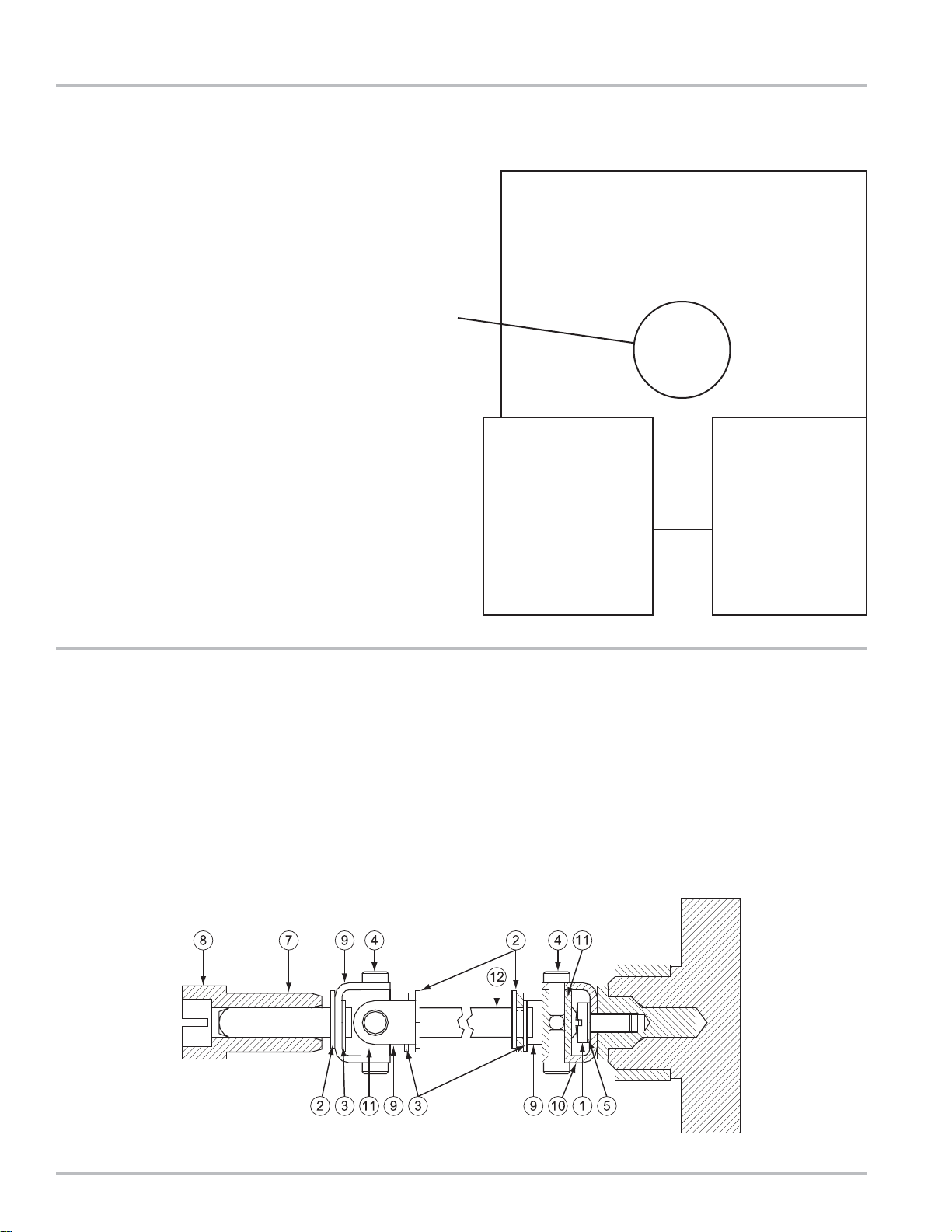
Universal Joint Assembly
12. The Universal Joint is an extension used to connect
the blocking rotor of the meter to the packing gland.
When the blocking rotor rotates, the Universal Joint
causes the packing gland to rotate which drives the
register. This assembly extends through the back of
the meter and into the weldment wall through the
drive coupling bearing.
Universal Joint Components
1. Screw, #8-32
2. Retaining Ring (3)
3. Retaining Ring (3)
4. U-Joint Pin (8)
5. Lock Washer
6. Coupling
Blocking Rotor
Connection
7. Drive Coupling
8. Driver Packing
9. U-Joint Bracket
10. Coupling
11. Trunnion
Packing Gland
Connection
26
Page 27

Tools:
Cover socket or open end/box end wrench
Spare displacement rotor gear or shop rag
Rotor gear wrench or socket
Bearing plate wrench or socket
(See Pages 31 & 32 for the Torque and Wrench & Socket Size Charts)
Installing the Meter
1. Place the flat gasket in the lower weldment and line
up the bolt holes. Position the meter housing in the
weldment lower hemisphere and secure using the
four bolts. Use care not to damage the flat gasket.
Use an impact driver or socket to tighten bolts.
Reassembling the Meter
NOTE: The principles of meter disassembly and
reassembly are the same for all Liquid Controls meters.
Although your meter may look slightly different than those
pictured, the steps are the same, except as noted.
Assembling the Meter
2. Install the blocking rotor. It will be necessary to guide
the universal joint assembly into the drive coupling
bearing and packing gland by reaching behind the
meter element.
27
Page 28

Reassembling the Meter
3. Install the two displacement rotors. Insert the nontapered ends into the housing. Place each rotor into
its respective bore on the bearing plate.
4. Install the bearing plate cover over the three t apered
ends and fasten it with the bearing plate screws. Use
the bearing plate wrench. The number of screws
varies between different meter sizes.
5. Install the rotor keys. The rotor key is a small wedge
of metal. Position the keys in each one of the three
rotors. Press the keys into the rotor keyways.
28
Page 29

Rotor Gear Timing
6. Slide the blocking rotor gear on its tapered rotor end.
Slide the right displacement rotor gear on its tapered
rotor end so that the timing marks line up between
the two gears.
HINT : Before placing the right displacement rotor gear
on its end, hold the right rotor gear in position. T urn
the blocking rotor gear. Line up the timing marks
before placing the right displacement rotor gear on
its tapered end.
7. Slide the left displacement rotor gear on its tapered
rotor end so that its timing mark lines up with the
blocking rotor gear.
Reassembling the Meter
8. Insert the rotor gear screw and flat washer into each
of the rotor gears and finger tighten.
9. Position the spare displacement rotor gear between
the left displacement rotor and the blocking rotor gear
to prevent the gears from moving. If a replacement
gear is not available, use a shop rag between the
teeth of the gears. Tighten the screws of the
displacement rotor gears to the torque specification
listed in the Torque Chart.
10. Position the spare displacement rotor gear between
the right displacement rotor and the blocking rotor
gear to prevent the gears from moving. Tighten the
screw of the blocking rotor gear to the torque
specification listed in the Torque Chart.
11. Rotate the gears to make sure that the rotors turn
freely. Burrs, foreign material, or marred surfaces
can restrict the rotor movements. It may be
necessary to remove the gears and rotors and deburr
or clean the surfaces again.
29
Page 30
Reassembling the Meter
Reassembling the Weldment Assembly
12. Install a new O-Ring in the groove around the
weldment base assembly if required.
13. Position the weldment cover on top of the weldment
base so that the cover vent plug is on top.
Install the screws around the rim of the weldment
cover. Attach the nuts to the back of each screw.
Begin by hand-tightening each of the screws. Once
this is complete, tighten the nuts and bolts to the
proper torque following the tightening sequence on
Page 31.
14. To complete the reassembly, reinstall the adjuster
and drive components. When this is complete,
reinstall the dust cover.
30
Page 31

Bolt Tightening Sequence
When placing the weldment cover on the weldment base,
it is important that the bolts are tightened in a sequence
which reduces the risk of leaking when the system is put
back in service. The number of bolts will vary depending
on the size of the meter. The general pattern should be
followed as pictured.
It is important to ensure that the O-Ring does not get
pinched during this process.
Tighten the bolts following the pattern to 50% of the
nominal torque. When all the bolts are torqued to 50%,
they should then be torqued to the proper setting following
the same pattern. Follow the torque specifications listed.
When replacing fastener elements, it is recommended
to use compatible components.
Wrench and Socket Size Chart
Meter
Model
MS-7
MSB-7
MSA-7
MSAA-7
MSC-7
MS-15
MSA-15
MSAA-15
MSB-15
MSC-15
MS-30
MSA-30
MSAA-30
MS-40
MSB-30
MSC-30
MS-75
MSA-75
MSAA-75
MSB-75
MSC-75
MS-120
MSA-120
MSAA-120
Dust
Cover
Screws
slotted
screwdriver
slotted
screwdriver
slotted
screwdriver
slotted
screwdriver
slotted
screwdriver
slotted
screwdriver
slotted
screwdriver
slotted
screwdriver
slotted
screwdriver
WRENCH/ S OCKET USE D
Me t er E lemen t Weldment Assembly
Counter
Bracket
Screws
1/4" Allen
wrench
1/4" Allen
wrench
1/4" Allen
wrench
1/4" Allen
wrench
1/4" Allen
wrench
1/4" Allen
wrench
1/4" Allen
wrench
1/4" Allen
wrench
1/4" Allen
wrench
Bearing
Plate
Screws
7/16" wrench/
socket
7/16" wrench/
socket
7/16" wrench/
socket
7/16" wrench/
socket
7/16" wrench/
socket
7/16" wrench/
socket
7/16" wrench/
socket
1/2" wrench/
socket
1/2" wrench/
socket
Rotor
Gear
Screws
3/8" wrench/
socket
3/8" wrench/
socket
3/8" wrench/
socket
3/16" Allen
wrench
3/16" Allen
wrench
3/16" Allen
wrench
3/16" Allen
wrench
9/16" wrench/
socket
9/16" wrench/
socket
Element
Mounting
Bolts
1/ 4" Allen
wrench
1/ 4" Allen
wrench
1/ 4" Allen
wrench
1/ 4" Allen
wrench
1/ 4" Allen
wrench
9/16" wrench/
socket
9/16" wrench/
socket
15/16" wrench/
socket
15/16" wrench/
socket
Drain
Plug
13/16" 4-point
socket
13/16" 4-point
socket
13/16" 4-point
socket
13/16" 4-point
socket
13/16" 4-point
socket
16" 4-point
13/
socket
13/16" 4-point
socket
13/16" 4-point
socket
13/16" 4-point
socket
Cover
Vent
Plug
9/16 4-point
socket
9/16 4-point
socket
9/16 4-point
socket
13/16" 4-point
socket
13/16" 4-point
socket
13/16" 4-point
socket
13/16" 4-point
socket
13/16" 4-point
socket
13/16" 4-point
socket
Weldment
Cover
3/4" wrench/
socket
9/16" wrench/
socket
15/16" wrench/
socket
9/16" wrench/
socket
1-5/16" wrench/
socket
3/4" wrench/
socket
1-5/8 wrench/
socket
15/16" wrench/
socket
1-1/8" wrench /
socket
31
Page 32

r
r
(
(
(
(
(
(
(
A
Fastener and Torque Chart
FASTENERS USED
Meter Element Weldment Assembly
Meter
Model
MS-7
MSB-7
MSA-7
MSAA-7
MSC-7
MS-15
MSA-15
MSAA-15
MSB-15
MSC-15
MS-30
MSA-30
MSAA-30
MS-40
MSB-30
MSC-30
MS-75
MSA-75
MSAA-75
MSB-75
MSC-75
MS-120
MSA-120
MSAA-120
Dust
Cover
Screws
(6) #10-2 4 x .38
FL ST R HD SLO T .
(6) #10-2 4 x .38
FL ST R HD SLO T .
(6) #10-2 4 x .38
FL ST R HD SLO T .
(6) #10-2 4 x .38
FL ST R HD SLO T .
(6) #10-2 4 x .38
FL ST R HD SLO T .
(6) #10-2 4 x .38
FL ST R HD SLO T .
(6) #10-2 4 x .38
FL ST R HD SLO T .
(6) #10-2 4 x .38
FL ST R HD SLO T .
(6) #10-2 4 x .38
FL ST R HD SLO T .
Counter
Bracket
Screws
(4) .312-18x1
HX. HD. SS.
(4) .312-18x1
HX. HD. SS.
(4) .312-18x1
HX. HD. SS.
(4) .312-18x1
HX. HD. SS.
(4) .312-18x1
HX. HD. SS.
(4) .312-18x1
HX. HD. SS.
(4) .312-18x1
HX. HD. SS.
(4) .312-18x1
HX. HD. SS.
(4) .312-18x1
HX. HD. SS.
Bearing
Plate
Screws
(10) .250-20x.75
HX. HD. SS
(10) .250-20x.75
HX. HD. SS
(10) .250-20x.75
HX. HD. SS
(12) .250-20x.75
HX. HD. SS
(12) .250-20x.75
HX. HD. SS
(16) .250-20x1
HX. HD. SS
(16) .250-20x1
HX. HD. SS
(20) .312-18x1
HX. HD. SS
(20) .312-18x1
HX. HD. SS
Rotor
Gear
Screws
(3) #10-24x.625
HX. HD. SS.
(3) #10-24x.625
HX. HD. SS.
(3) #10-24x.625
HX. HD. SS.
(3) .250-20x.7 5
SCK. HD. SS
(3) .250-20x.7 5
SCK. HD. SS
(3) .250-20x.7 5
SCK. HD. SS
(3) .250-20x.7 5
SCK. HD. SS
(3) .375-16x1. 25
HX. HD. SS.
(3) .375-16x1. 25
HX. HD. SS.
Element
Mounting
Bolts
(4) .312-18x.75
HX. SCK. HD
(4) .312-18x.75
HX. SCK. HD
(4) .312-18x.75
HX. SCK. HD
(4) .312-18x1.2 5
HX. SCK. HD.
(4) .312-18x1.2 5
HX. SCK. HD.
(4) .375-16x1.2 5
HX. HD. GR8
(4) .375-16x1.2 5
HX. HD. GR8
(4) .625-11x2.5
HX. HD . GR 5
(4) .625-11x2.5
HX. HD . GR 5
Drain
Plug
(1) 1"-11.5
NPT SQ. HD.
(1) 1"-11.5
NPT SQ. HD.
(1) 1"-11.5
NPT SQ. HD.
(2) 1"-11.5
NPT SQ. HD.
(3) 1"-11.5
NPT SQ. HD.
) 1"-11.5
(3
NPT SQ. HD.
(3) 1"-11.5
NPT SQ. HD.
(3) 1"-11.5
NPT SQ. HD.
(3) 1"-11.5
NPT SQ. HD.
Cover
Vent
Plug
(2) .500-14
NPT SQ . HD.
(2) .500-14
NPT SQ . HD.
(2) .500-14
NPT SQ . HD.
(1) 1"-11. 5
NPT SQ . HD.
(1) 1"-11. 5
NPT SQ . HD.
(1) 1"-11. 5
NPT SQ . HD.
(1) 1"-11. 5
NPT SQ . HD.
(1) 1"-11. 5
NPT SQ . HD.
(1) 1"-11. 5
NPT SQ . HD.
Weldment
Cover
(12 ) . 5 00-13x1.75
HX. HD. G R 5
(16 ) . 3 75-16x1.75
HX. HD. G R 5
(20) .625-11x2.5
HX. HD. G R 5
(16) .375-11x2.5
HX. HD. G R 5
(24) .875-9x5
HX. HD. G R 5
(20 ) . 5 00-13x3
HX. HD. G R 8
(28) 1"-8x7
GR B7 STUD
(24 ) . 6 25-11x4
HX. HD. G R5
(24 ) . 7 50-10x3
HX. HD. G R 5
Torque Chart
Torque
Ref. #
Bolt Size
1 #8 (.164) - 32 UNC-2A 42 4.8
2 #10
.190) - 24 UN C-2
NOTE: ASTM A574 socket Head Cap Screw - Low Alloy Steel: quenched & tempered.
Torque
Ref. #
Bolt Size
3 1/4" (.250) - 20 UNC-2A 7.3 9.9 --- --4 5/16"
53/8"
6 7/16"
71/2"
85/8"
93/4"
.3125) - 18 UNC-2A 15.3 20.7 --- ---
.375) - 16 UNC-2A 27 37
.4375) - 14 UNC-2A 43 58 --- --.500) - 13 UNC-2A 66 90 112 152
.625) - 11 UNC-2A 132 17 9 222 301
.750) - 10 UNC-2A 233 31 6 395 535
*Torque Tolerance is ± 10%
Inch-Pounds Newton-Meter
NOMINAL* NOMINAL*
63 7.1
Grade 5 Grade 8
Foot-Pounds Newton-Mete
NOMINAL* NOMINAL* NOMINAL* NOMINAL*
Foot-Pounds Newton-Mete
--- ---
32
Page 33

Identification of Bolt Grades
T roubleshooting
Grade 0, 1, & 2
(No Markings)
Grade 3
2 radial dashes, 180º apart
Grade 5
3 radial dashes, 120º apart
Grade 6
4 radial dashes, 90º apart
Grade 7
5 radial dashes, 72º apart
Grade 8
6 radial dashes, 60º apart
Troubleshooting
Problem: Leakage past the packing gland drive shaft housing from internal metering chamber.
Probable Cause: Internal seal of the packing gland assembly is worn. Replace packing gland and O-Ring seal.
Operating Note: Two common causes of packing gland leakage are thermal expansion and hydraulic shock. If two
valves in a piping system (on either side of the meter) are closed at one time, and if the temperature rises as little
as 1ºF in the system, it could result in a rise in pressure (70 psi for every 1°F) within the system that would exceed
the working pressure rating of the meter. To avoid this hazard caused by thermal expansion, a pressure-relief
valve must be installed in the system. Hydraulic shock occurs when a large volume (mass) of liquid is moving
through a pipe line at some flow rate and a valve is suddenly closed. When the flow is stopped, the entire mass of
liquid in the piping system acts as a battering ram causing a shock effect within the meter. The greater the mass,
length of line, and/or velocity , the greater the hydraulic shock. Since the valve is usually located at the meter outlet,
the meter housing, packing gland and the meter internal components receive the full impact of such hydraulic
shock. To prevent this hazard, a slow closing, two-stage valve should be used with the meter. On those systems
where mass length of line, etc. are of such magnitude as to preclude elimination of hydraulic shock with the use of
a two-stage valve, an impact absorbing or cushioning device should be used.
Problem: Leakage from the cover gasket.
Probable Cause: Gasket has been damaged due to shock pressure, thermal expansion, or cover bolts that have not
been sufficiently tightened.
Problem: Breaking teeth on rotor timing gears.
Probable Cause:
1. Starting or stopping flow in the meter too rapidly.
2. Pump bypass not adjusted properly.
3. Shock due to start-up of an empty system. When liquid is introduced, shock can occur if not started slowly.
33
Page 34

T roubleshooting
Problem: Product flows through the meter but the register does not operate.
Probable Cause:
1. Check the packing gland and gear train.
2. If all meter parts are moving, the problem is in the register. Faulty registers should be checked and repaired by a
trained technician.
3. Remove the register from the meter. If all meter parts are moving but the output of adjuster assembly is not,
adjuster is worn and must be replaced.
4. If totalizer numbers (small numbers) on the meter are recording, but the large numbers are not moving, the register
needs repair.
5. The packing gland gear is not turning. The drive blade may be sheared. Replace the packing gland. This may be
caused by starting the flow too rapidly.
Problem: Product flows through meter but register does not record correctly.
Probable Cause:
1. Adjuster not properly calibrated.
2. Incorrect gear plate or gear ratio has been installed.
3. Meter is damaged.
4. There is air in the system
Problem: No flow through meter.
Probable Cause:
1. Faulty pump.
2. Valve not open or not functioning.
3. Meter “frozen” due to buildup of chemical “salts” or foreign material inside the metering chamber. To correct, clean
the meter and inspect for damage.
Problem: Meter runs too slowly.
Probable Cause:
1. Valve internal mechanism faulty. Valve does not open fully.
2. Meter gears or rotors partially “salted” enough to slow up rotation of parts. To correct, clean the meter.
3. The strainer basket is partially clogged.
Problem: The meter counts down (the numbers decrease).
Probable Cause: It is necessary to reverse the direction of flow by reversing the adjuster drive gear. See Meter Start
Up & Operation on Page 12 of this manual.
34
Page 35

1. Refer to the exploded drawings of the meter on Pages
36-39. Find the four digit item number for the part
you want to order.
2. Find the computer printout titled Bill of Materials that
has been inserted in the red Owner’s Information
Packet. Look up the item number on the Bill of
Materials. The Bill of Materials shows each item
number with a corresponding part number. Find the
corresponding part number for the item you want to
order. The part number represents an individual
piece, a kit, or a complete assembly.
3. Inform your distributor of the part number that you
need. The part number is the only number that allows
the distributor to find the correct component for your
meter.
How to Order Replacement Parts
35
Page 36

Illustrated Parts Breakdown
Adjuster Housing Assembly
NOTE: Numbers shown are ITEM numbers, not Part Numbers. Refer to the Bill of Materials supplied in the red
Owner’s Information Packet to locate the PART NUMBER associated with these ITEM NUMBERS.
36
Page 37

Weldment Assembly
Illustrated Parts Breakdown
NOTE: Numbers shown are ITEM numbers, not Part Numbers. Refer to the Bill of Materials supplied in the red
Owner’s Information Packet to locate the PART NUMBER associated with these ITEM NUMBERS.
37
Page 38

Illustrated Parts Breakdown
Meter Element Assembly
NOTE: Numbers shown are ITEM numbers, not Part Numbers. Refer to the Bill of Materials supplied in the red
Owner’s Information Packet to locate the PART NUMBER associated with these ITEM NUMBERS.
38
Page 39

Complete Assembly
Illustrated Parts Breakdown
NOTE: Numbers shown are ITEM numbers, not Part Numbers. Refer to the Bill of Materials supplied in the red
Owner’s Information Packet to locate the PART NUMBER associated with these ITEM NUMBERS.
39
Page 40

A Unit of IDEX Corporation
105 Albrecht Drive
Lake Bluff, IL 60044-2242
1.800.458.5262 • 847.295.1050
Fax: 847.295.1057
www.lcmeter.com
© 2006 Liquid Controls
Pub. No. 500318
(4/13)
 Loading...