

Page 1
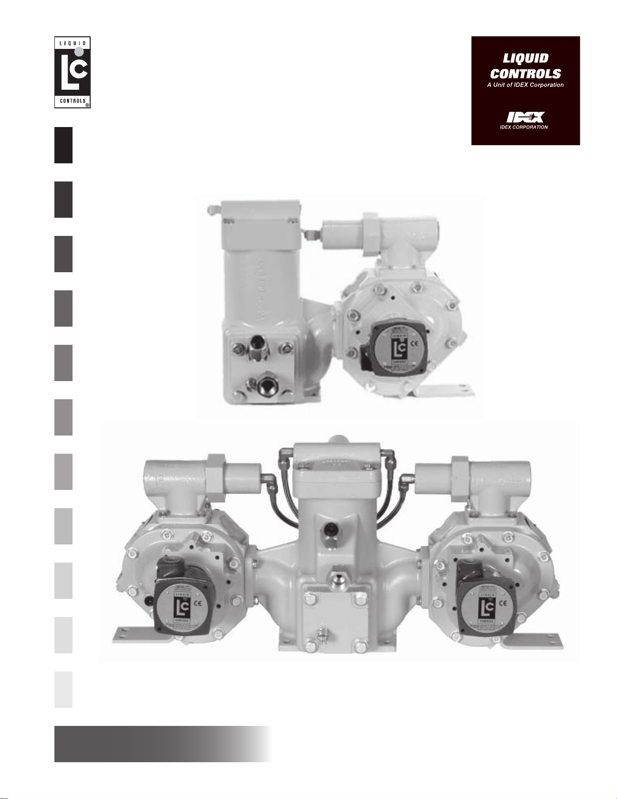
Installation & Parts Manual
MA-4 Positive Displacement Meter for
LPG Motor Fuel Dispensers
(Single & Dual Meter Versions)
Installation: M100-11
www.lcmeter.com
Page 2

Table of Contents
Description Page Number
Safety Precautions ..............................................2
How LC Meters Work ..........................................3
Owner’s Information Packet ................................4
Installation Requirements....................................4-5
Installation ...........................................................6-9
Mounting Dimensions - Single Meter......6
Mounting Dimensions - Dual Meter ........7
Operation Requirements ........................8
Meter Installation ....................................8
Meter Start Up & Operation ....................9
Meter Maintenance .............................................10-11
Pulse Output Device 5 (POD5) ...........................12-14
Vapor Eliminator/Strainer Maintenance ...............15-16
Differential Valve Maintenance ............................17
Please have the following information available when you
make inquiries, order replacement parts, or schedule
service. If a specific meter accessory is involved, please
provide the model and serial number of the meter in
question (See Page 4).
Meter Serial Number____________________________
Full Service Distributor___________________________
Full Service Distributor Phone Number______________
Disassembling the Meter.....................................18-19
Removing the Non-Corroded Rotor Gears..........20
Removing Bearing Plates and Rotors .................20
Removing Corroded Rotor Gears........................21
Reassembling the Meter .....................................22-23
Timing the Rotor Gears .......................................24
Torque Chart .......................................................25
Wrench and Socket Size Chart ...........................25
Troubleshooting ................................................... 26
How to Order Replacement Parts .......................27
Meter Assembly Exploded View ..........................28
Strainer Assembly Exploded View.......................29
Differential Valve Exploded View.........................30
Optional Back Check Valve Assembly.................31
Publication Updates & Translations
The most current English versions of all Liquid Controls
publications are available on our website,
www.lcmeter.com. It is the responsibility of the Local
Distributor to provide the most current version of LC
Manuals, Instructions, and Specification Sheets in the
required language of the country, or the language of the
end user to which the products are shipping . If there
are questions about the language of any LC Manuals,
Instructions, or Specification Sheets, please cont act your
Local Distributor.
!!
WARNING WARNING
!
WARNING
!!
WARNING WARNING
• Before using this product, read and understand the instructions.
• Save these instructions for future reference.
• All work must be performed by qualified personnel trained in the proper application, installation, and
maintenance of equipment and/or systems in accordance with all applicable codes and ordinances.
• Failure to follow the instructions set forth in this publication could result in property damage, personal injury,
or death from fire and/or explosion, or other hazards that may be associated with this type of equipment.
Safety Procedures
!!
! WARNING
!!
All internal pressures must be relieved before
disassembly or inspection of the strainer, air eliminator ,
any valves in the system, the packing gland, and the
front or rear covers. See “Relieving Internal Pressure”
(Page 10).
Be Prepared
Make sure that all necessary safety precautions have
been taken. Provide for proper ventilation, temperature
control, fire prevention, evacuation and fire management.
Provide easy access to the appropriate fire extinguishers
for your product. Consult with your local fire department
and state and local codes to make sure that you are
adequately prepared.
Read this manual as well as all the literature provided in
your owner’s packet.
In the Event of a Gas Leak
In the event of a large gas leak: Evacuate the area
and notify the fire department.
In the event of a small, contained gas leak:
1. Stop the leak and prevent accidental ignition.
2. Prevent the entrance of gas into other portions of
the buildings. Some gases, such as LPG , seek lower
levels, while other gases seek higher levels.
3. Evacuate all people from the danger zone.
2
Page 3
How LC Meters Work
4. See that the gas is dispersed before resuming
business and operating motors. If in doubt, notify
your local fire department.
In the Event of a Gas Fire
In the event of large fires or fires that are spreading:
Evacuate the building and notify your local fire
Liquid Controls meters are positive displacement meters.
They are designed for liquid measurement in both
custody transfer and process control applications. They
can be installed in pump or gravity flow systems. Because
of their simple design, they are easy to maintain, and
easy to adapt to a variety of systems.
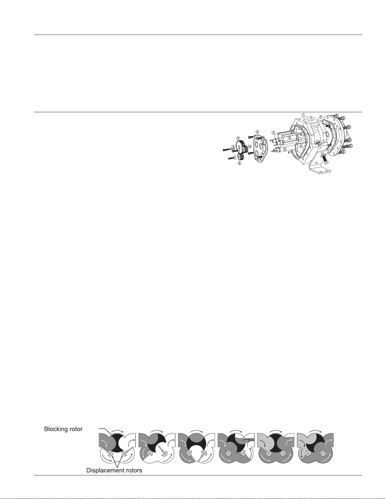
The meter housing (1) is designed with three cylindrical
bores (2). Three rotors, the blocking rotor (3) and two
displacement rotors (4, 5), turn in synchronized
relationship within the bores. The three rotors are
supported by bearing plates (6, 7). The ends of the
rotors protrude through the bearing plates. Blocking rotor
gear (8) is placed on the end of the blocking rotor.
Displacement rotor gears (9, 10) are placed on the ends
of the displacement rotors. These gears create the
synchronized timed relationship between the three rotors.
As fluid moves through the meter housing, the rotor
assembly turns. The liquid is broken into uniform sections
by the turning rotors. Fluid displacement happens
simultaneously. As fluid enters, another portion of the
fluid is being partitioned and measured. At the same
time, the fluid ahead of it is being displaced out of the
meter and into the discharge line. Since the volume of
the bores is known, and the same amount of fluid passes
through the meter during each revolution of the blocking
rotor, the exact volume of liquid that has p assed through
the meter can be accurately determined.
This true rotary motion is transmitted through the packing
gland, the face gear, the adjuster drive shaft, and the
adjuster to the register stack and counter. True rotary
motion output means consistent accuracy since the
register indication is in precise agreement with the actual
volume throughput at any given instant.
At any position in the cycle, the meter body , the blocking
rotor, and at least one of the displacement rotors form a
continuous capillary seal between the un-metered
department. Stop the leakage only if you can safely reach
the equipment.
In the event of small, contained fires that you can
safely control: Stop the leakage if you can safely reach
the equipment. Then use the appropriate extinguisher:
Class B fire extinguisher, water, fog, etc., depending on
the materials. If in doubt, call your local fire department.
Meter Element Exploded View
upstream product and the metered downstream product.
Capillary seals mean no metal-to-metal contact within
the metering element. This means no wear. No wear
means no increase in slippage, and no increase in
slippage means no deterioration in accuracy.
Throughout the metering element, the mating surfaces
are either flat surfaces or cylindrical faces and sections
that are accurately machined. These relatively simple
machining operations, plus the fact that there is no
oscillating or reciprocating motion within the device,
permits extremely close and consistent tolerances within
the LC meter.
The product flowing through the meter exerts a dynamic
force that is at right angles to the faces of the
displacement rotors. The meter is designed so that the
rotor shafts are always in a horizontal plane. These two
facts result in no axial thrust. Therefore, with no need
for thrust washers or thrust bearings, the rotors
automatically seek the center of the stream between the
two bearing plates eliminating wear between the ends
of the rotors and the bearing plates. Once again, no
wear results in no metal fatigue and no friction.
The Liquid Controls meters are made of a variety of
materials to suit a variety of products. Because of our
no-wear design, capillary seals, and unique rotary
metering, LC meters provide unequalled accuracy, long
operating life, and unusual dependability.
3
Page 4
Owner’s Information Packet
Is all your documentation included with your meter? LC
meters come in many variations. The information sent to
you depends on the accessories you have ordered with
your meter. Make an inventory of your Owner’s
Information Packet. First, find your LC packing slip with
the computer printout. Locate the serial number and the
meter model number on this printout. Cross-reference
the packing slip with the actual meter serial numbers.
Included in your Owner’s Information Packet are the
following:
• Installation and Parts Manual
• Bill of Materials
• SCAMP™ Installation and Operation Manual
Record your meter serial number in the space provided
on the inside cover of this manual. The inside cover also
provides a space for your full-service distributor’s name
and telephone number, if applicable. Fill in this
information and keep it handy. Y ou will always need your
meter serial number and model number when calling for
service or parts. See “How to Order Replacement Parts”
on Page 27 in this manual.
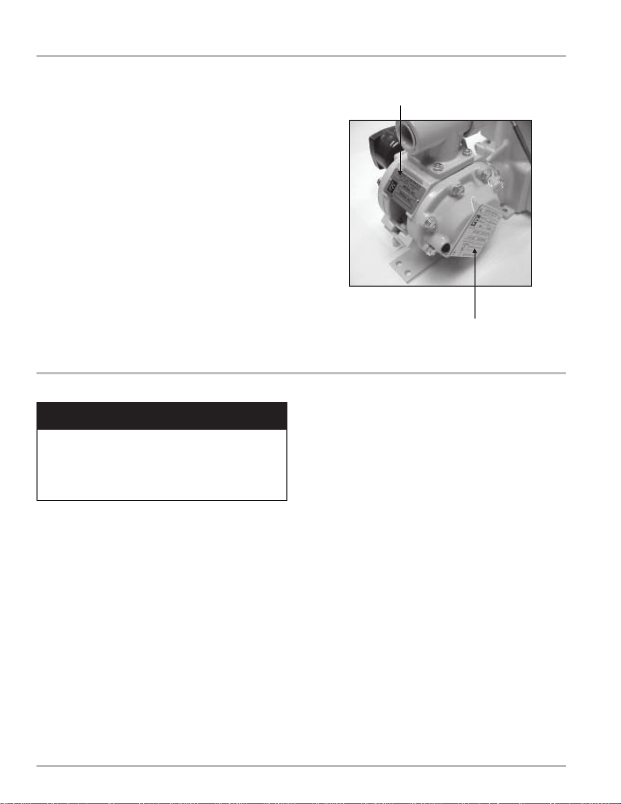
Serial Number Plate (Side)
Serial Number Plate (Rear)
Installation Requirements
!!
! WARNING
!!
All internal pressures must be relieved before
disassembly or inspection of the strainer, air eliminator ,
any valves in the system, the packing gland, and the
front or rear covers. See “Relieving Internal Pressure”
(Page 10).
• Make sure that all necessary safety precautions
have been taken. Provide for proper ventilation,
temperature control, fire prevention, evacuation,
and fire management.
• Provide easy access to the appropriate fire
extinguishers for your product. Consult with your
local fire department and state and local codes to
make sure that you are adequately prepared.
• Read this manual as well as the literature provided
in your Owner’s Information Packet. If you have any
questions, consult with your full-service distributor
or call the Service Department at Liquid Controls.
• Install the meter and accessories in conformance with
all applicable federal, state, local, construction,
electrical, and safety codes.
• Class 10 meters for LPG must be installed in
accordance with the requirements of ANSI-NFPA 58
in addition to all other state and local codes.
• Under normal operation, do not expose any portion
of the LP-Gas system to pressures in excess of rated
working pressures without an automatic safety valve
to vent the over pressure discharge to a place of
safety away from the operator and other people.
Failure to provide such a safety relief may result in
leakage or rupture of one or more of the components
in the system. This can result in injury or death from
the gas, a fire, or pieces of flying debris from the
rupture.
• Before shipment, protective thread caps were placed
in all meter and accessory openings. They should
remain in place until you are ready to attach piping.
• Prior to meter installation, the entire piping system
should be thoroughly flushed of all debris, with a liquid
that is compatible with the construction of the meter .
• Keep all external surfaces of the meter clean.
• Apply pipe compound to male threads only.
4
Page 5

Installation & Operation Requirements
!!
! WARNING
!!
When a Back Check V alve is used, an automatic safety
valve must be installed to prevent pressure build-up in
excess of rated working pressure in the meter housing.
One automatic safety valve should be installed in each
meter. Remove the pipe plug from the front cover or
rear cover and insert the appropriate automatic safety
valve.
• The meter must always be securely bolted to a
platform or supporting member, regardless of the
mounting position of the meter. Never “hang” a meter
on the connecting pipe.
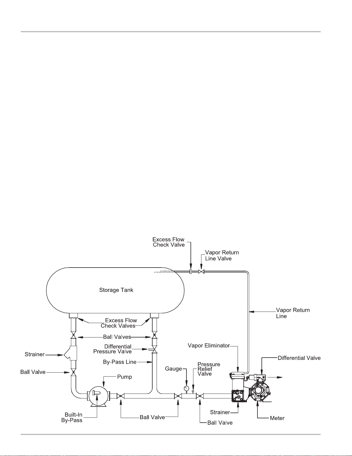
Operation Requirements
The meter must remain full of product at all times. An
easy way to accomplish this is to put the meter assembly
in the line below the piping center-line (a sump position).
This requires adding elbows and flanges prior to installing
the meter. The meter should be installed in a bypass loop,
below the pipe center-line, with block valves upstream
and downstream. A block valve should be located in the
mainstream, labeled as the bypass valve. A word of
caution: any portion of pipe system that might isolate or
block flow should be provided with a pressure relief to
prevent damage from thermal expansion. There are
excellent benefits to this type of installation. First, the
meter is kept full. Second, this type of installation allows
the meter to be isolated for servicing and calibration while
continuing flow through the bypass valve.
Upstream lines must be maintained full to prevent air
from entering the meter. If the up stream or inlet lines are
constructed in a manner which allows reverse flow, foot
valves or back checks must be installed.
Position the meter with service in mind. Make sure there
is ample work space. Removing the meter covers can
be difficult when ample work space is not available.
Always supply a platform or support for the meter
mounting.
Every meter should be calibrated under actual service
and installation conditions per the API Manual of
Petroleum Measurement Standards:
Chapter 4 - Proving Systems
Chapter 5 - Metering
Chapter 6 - Metering Assemblies
Chapter 11 Section 2.3 - Water Calibration of
Volumetric Provers
Chapter 12 Section 2 - Calculation of Petroleum
Quantities
• Position the meter with service in mind. Provide
ample work space. Removing covers can be difficult
when work space is not available. Always supply a
platform or support for the meter mounting.
• A meter is metallurgically designed to be physically
compatible with a given type of liquid, as originally
specified by the customer, and as indicated on the
Serial Number Plate. A meter should not be used
with a liquid different from the liquid originally
specified, unless the physical characteristics and pH
rating are similar and the application has been
checked with Liquid Controls Sales or Engineering.
These chapters of the API Manual of Petroleum
Measurement Standards supersede the API Standard
1101.
Provide a means of conveniently diverting liquid for
calibration purposes.
Give careful attention to your system’s pumping
equipment and piping because of their influence on liquid
being measured as it enters the meter assembly. Systems
should be made free of conditions that cause or introduce
entrained air or vapor.
Follow the manufacturer’s recommendations fully when
installing pumps. Give particular attention to factors like:
use of foot valves, pipe size to the inlet and conformance
to net positive suction head (NPSH) conditions when
suction pumping is required. Following the manufacturer’s
recommendations will minimize air and vapor elimination
problems.
For liquids such as light hydrocarbons that tend to flash
or vaporize easily at higher ambient temperatures, it is
desirable to use flooded suctions and piping sized larger
than the normal pump size.
Hydraulic shock is harmful to all components of an
operating system including valves, the meter and the
pump. In particular, meters must be afforded protection
from shock because of their need to measure with high
precision. Generally the best protection is prevention,
which can be readily accomplished by adjusting valve
closing rates in such a manner that shock does not occur.
Thermal expansion like hydraulic shock is a phenomenon
that can easily damage meters and systems in general.
Care should be taken in designing the system to include
pressure relief valves in any portion or branch of the
system that might be closed off by closure of operating
valves or block valves.
5
Page 6
Installation
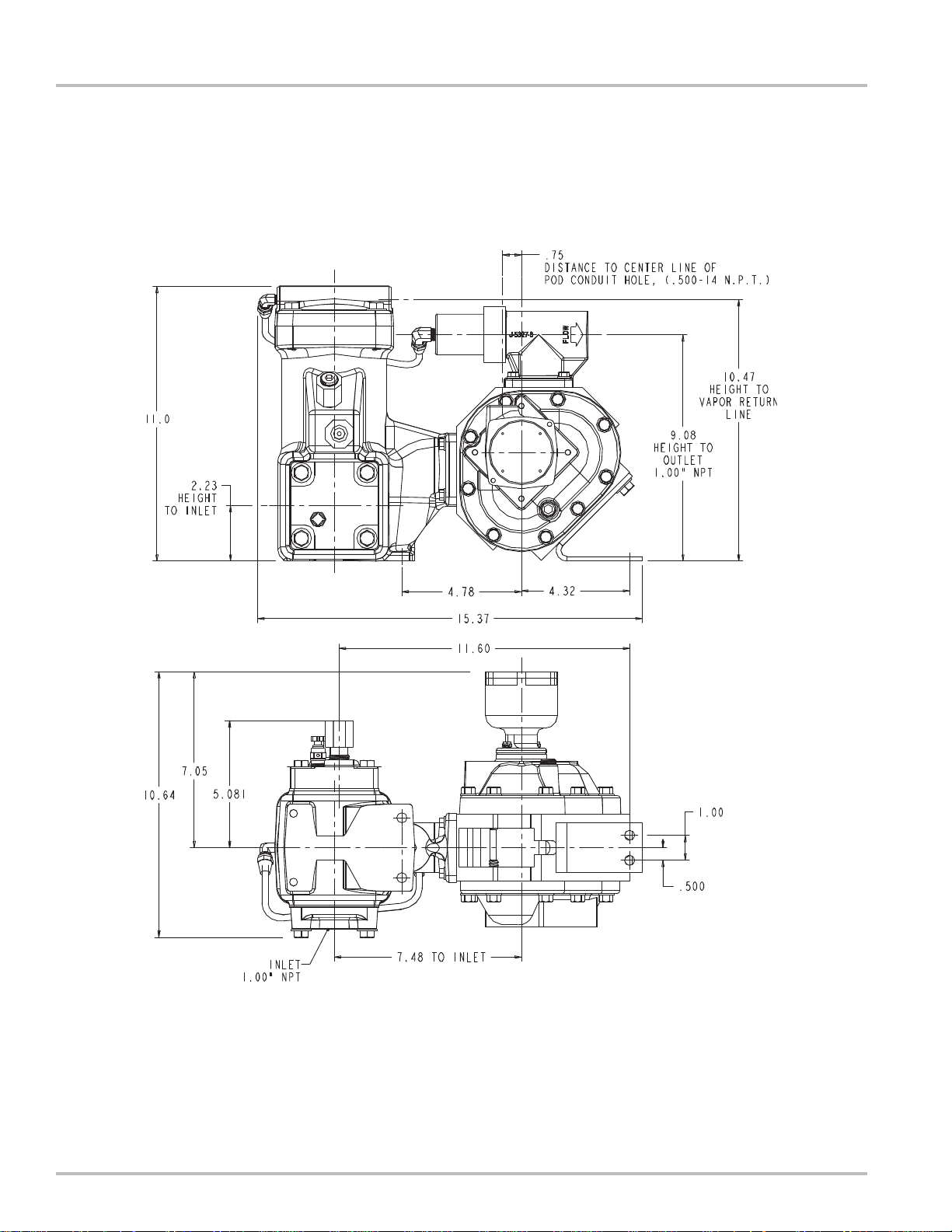
Mounting Dimensions - Single Meter
NOTE: Always request up-to-date engineering approved dimensional drawings before starting any construction. Do
not rely on catalog pictures or drawings, which are for reference only. After receiving the prints, check to see that all
equipment ordered is shown and that any extra pressure taps, plugs, etc. are noted and their size specified.
6
Page 7
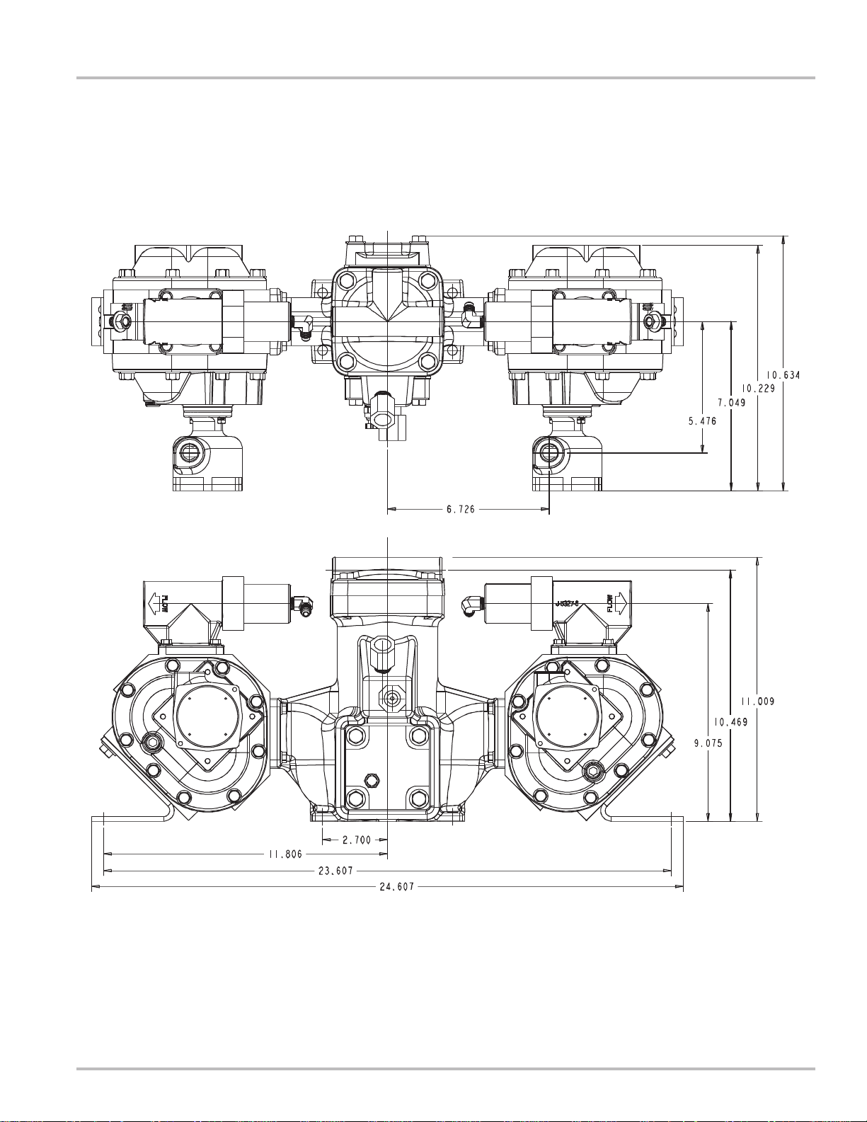
Mounting Dimensions - Dual Meter
Installation
NOTE: Always request up-to-date engineering approved dimensional drawings before starting any construction. Do
not rely on catalog pictures or drawings, which are for reference only. After receiving the prints, check to see that all
equipment ordered is shown and that any extra pressure taps, plugs, etc. are noted and their size specified.
7
Page 8
Installation
Theory of Operation
The Liquid Controls MA-4 LPG Meter combines a positive
displacement meter, dif ferential valve, strainer, and vapor
eliminator in one assembly.
The Liquid Controls vapor eliminator employs a sleevetype valve that permits a “leak” flow of approximately 0.2
GPM from the vapor vent back to the supply tank. A 200mesh strainer is incorporated in the vapor eliminator
casting and is easily accessible by removing the strainer
cover.
The Liquid Controls differential valve incorporates a
piston-diaphragm type construction, with the piston
moving away from its seat when at least 15 psi pressure
(above product vapor pressure) is maintained at the meter
outlet. The soft seat valve assures measurement
accuracy by requiring 1) pump operation for delivery, 2)
adequate back pressure to prevent product vaporization
during measurement, and 3) blockage of flow when the
vapor eliminator release valve opens.
Meter Installation
Meter:
Install the meter assembly in dispenser cabinet to a
secure base, using the supplied bracket on the meter
housing and the “feet” located on the strainer assembly
base. Make inlet and outlet connections at the flanged
surfaces on the strainer and differential valve,
respectively.
Vent Line:
The vent line from the meter’s vapor vent to the vapor
space on the supply tank should be 1/4 inch minimum
inside diameter tube or pipe. A shut off valve must be
installed in the vapor vent line to allow removal of the
strainer or to service the meter. The vapor release vent
line must be returned to the vapor space of the supply
tank and normally should not be made common with the
other vapor return lines or pump bypass lines. When
properly installed, this line must permit free flow in either
direction. If the valve in the vent line is closed the
meter will not function. These instructions must be
followed to maintain proper function of the differential
valve.
8
Page 9

Meter Start-up and Operation
Prior to meter start up, use extreme caution. Make sure
that:
1. The meter is properly secured
2. All connections are tight
3. All valves are in the closed position
Placing your meter in operation:
Check to determine that all fittings and flanges are tight
and liquid lines are closed.
Open the vapor line to the meter. Using vapor pressure
only, check each joint with a liquid soap solution to see
that no leaks go undetected. When all joints have been
checked, admit liquid SLOWLY to avoid operation on
vapor at speeds greater than the minimum indicated on
the serial number plate and to insure that cover cavities
do not contain vapor which can be compressed. Proper
slow filling can be done by throttling the system with a
valve at the meter OUTLET or by allowing the system to
fill by gravity.
With the valve(s) open between the tank and the meter,
go to the valve located down stream of the meter. Open
the down stream valve slowly until the meter’s register/
counter starts to move. Do not run the meter any faster
than 25% of its maximum rated flow during start-up. Once
the product is flowing out the end of your system, the
outlet valve can be opened all the way provided that the
system is designed not to exceed the flow rate marked
on the meter.
Installation
Never operate the meter or system when partially filled
with liquid, or with pockets of compressed air or vapor
present. If these conditions cannot be avoided, air and
vapor elimination systems may be required. If you cannot
fill the meter slowly by gravity or by using a valve to throttle
back the flow, consult the factory.
Do not operate the meter at a pressure exceeding that
marked on the Serial Number Plate. Under any and all
pressure producing circumstances, for instance, thermal
expansion and hydraulic shock, the working pressure
must not exceed the indicated maximum.
If the meter is operated at a rate greater than the
maximum recommended GPM, excessive wear and
premature failure may occur.
The meter can be calibrated for flows below minimum
ratings if the flow remains constant and varies within
narrow limits or if the product is viscous. A meter should
never be run beyond the maximum flow rate determined
for that class meter and/or liquid measured.
NOTE: If the valves are not manual, consult the valve
manufacturer for slow flow start-up.
Filling the system with a pump:
Consult the pump manufacturer for proper pump priming.
Once the pump is primed with product, proceed.
CAUTION!
Make sure that your pump can operate against a dead
head pressure. If NOT, consult the factory for
assistance.
9
Page 10

Meter Maintenance
!!
! WARNING
!!
Relieving Internal Pressure
All internal pressure must be relieved to zero pressure
before disassembly or inspection of the strainer, air eliminator any valves in the system,
the packing gland, and the front or rear covers.
Serious injury or death from fire or explosion could result from maintenance of an
WARNING
improperly depressurized and evacuated system.
Procedure for Non-LPG Meters
1. Turn off pump pressure to the system.
2. Close valves before and after the meter.
3. Remove pressure by removing the drain plugs and
draining the meter.
Procedure for LPG Meters
1. Close the belly valve of the supply tank.
2. Close the valve on the vapor return line.
3. Close the manual valve in the supply line on the inlet
side of the meter. If no manual valve exists on the
inlet side, consult the truck manufacturer for
procedures to depressurize the system.
Prevent pipe strain or stress from occurring when making
meter or accessory repairs. Pipe strain and stress occur
when the pipes are not supported or are not aligned
correctly to the meter. The weight of the pipes must
always be supported independent of the meter. This
means that the meter and accessories can easily be
removed without affecting the pipes or the pipe alignment.
Never leave any of the pipes hanging.
Seasonal meter storage. If the meter is used for seasonal
work, at the end of each season the meter should be
removed from the system and thoroughly flushed with a
compatible liquid. This includes removing the drain on
the front and rear covers. Then flush the product from
the front and rear covers. If flushing with water is
preferred, extra care should be taken to drain the meter
completely and to dry all internal parts. Immediate refilling
with a compatible liquid (or oil misting) is essential to
prevent corrosion as well as ice damage to parts from
moisture that was overlooked after flushing and drying.
Do not mar or scratch any of the precision machined
surfaces by prying or sanding parts.
4. Slowly open the valve/nozzle at the end of the supply
line.
5. After product has bled off, close the valve/nozzle at
the end of the supply line.
6. Slowly crack the fitting on top of the differential valve
to relieve product pressure in the system. Product
will drain from the meter system.
7. As product is bleeding from the differential valve,
slowly reopen and close the valve/nozzle on the
discharge line. Repeat this step until the product
stops draining from the differential valve and
discharge line valve/nozzle.
8. Leave the discharge line valve/nozzle open while
working on the system.
Torque specifications. All fasteners such as screws and
bolts should be torqued to proper specification. See the
“Torque Chart” on Page 25 of this manual.
Stone the machined surfaces when reassembling the
meter to assure that the machined surfaces are free of
burrs and mars.
Repair pulled threads with threaded insert fasteners.
These can be used in many instances. Contact your
full-service distributor for advice if this occurs.
Coating threads. When removing and replacing bolts
and castings in a meter, always coat the threads with
anti-seize.
Removing flange seals. When removing the flange
assembly , always carefully remove the O-ring seal. Make
sure that the flange surface is clean. Discard and replace
the old O-Ring seal if it is nicked or scratched in any
way. If it is undamaged, it can be reused.
10
Page 11

Meter Maintenance
Examine all fasteners. Make sure fasteners are not bent,
rusted, or have pulled threads. The threads should all
appear evenly placed. If the bolts are bent, check the
housing and cover for flatness. Use a straight edge to
determine flatness.
Look for gaps. When disassembling a meter, use a feeler
gauge to check for gaps between the bearing plate and
housing. If you do find gaps, check the bearing plates for
flatness with a straight edge. Gaps can be caused by
shock problems that must be resolved. Contact your fullservice distributor or the Service Department at Liquid
Controls for assistance if this occurs.
Check the O-Rings. O-Rings should be smooth. Cracked
or worn O-Rings should be replaced. However, a more
serious problem of shock may have occurred if the ORings look nibbled. Shock problems must be verified and
resolved. Contact your full-service distributor or the
Service Department at Liquid Controls for assistance if
this occurs.
Check the bearing plates. Check the bearing plates for
flatness. Use a straight edge. Warped bearing plates can
be caused by shock problems that must be resolved.
Contact your full-service distributor or the Service
Department at Liquid Controls for assistance if this
occurs.
Weights & Measures. Check with the regulatory agency
that governs Weights & Measures in your area. Removing
a seal wire may require Weights & Measures
recalibration.
11
Page 12

Pulse Output Device (POD5)
The Liquid Controls Pulse Output Device (POD) converts
the rotary motion of the Positive Displacement Meter into
electronic pulses making it possible to interface the meter
to electronic monitoring and control equipment. The
POD5 was specifically designed to interface with the MA4 meter and the SCAMP A™ electronics.
The POD5 mounts directly to the front cover of the MA-4
meter. The motion of the meter’s blocking rotor is
magnetically coupled through a stainless steel wall into
the electronics compartment of the POD5. This
eliminates any dynamic seal and isolates the electronics
from the process fluid in the meter.
Inside the POD5 electronics compartment an optical shaft
encoder converts the rotary motion into a high resolution,
two-channel quadrature square wave. Both outputs
switch from 5 volts in the “ON” state to zero volts in the
“OFF” state.
The POD5 electronics compartment also serves as a
conduit junction box. The POD5 has an O-Ring sealed,
threaded cover. The standard wire entrance is a 1/2-14
NPT female hub, which accepts threaded conduit or a
cable gland. A plug-in connector on the encoder
facilitates wiring of the unit. With the wiring entrance
sealed and the cover in place, the housing is
ENCLOSURE TYPE NEMA 4X weatherproof rated. In
addition, the housing is CENELEC rated flameproof, and
UL and Canadian-UL explosion-proof rated when properly
installed with approved conduit.
!!
! WARNING
!!
All internal pressures must be relieved before
disassembly or inspection of the strainer, air eliminator ,
any valves in the system, the packing gland, and the
front or rear covers. See “Relieving Internal Pressure”
(Page 10).
INSTALLATION:
The POD5 comes factory installed on the meter ready
for wiring with the conduit orientation in the up position.
The hub can be oriented in one of four possible directions;
facing up, down, left, or right. If a different orientation is
required remove the two mounting screws and pull the
POD5 from the front cover. Remove the POD5 O-ring
from the cover.
• After determining the orientation of the conduit
hub, determine which two of the four mounting screw
holes will be used to fasten the POD5 to the front of the
meter cover. It is suggested that the mounting screws
be driven into these holes first to “pre-tap” the threads in
the meter cover. This will make it easier to thread the
screws when the POD5 is in place.
• Position the O-ring on the bottom of the POD5.
• Align the fork driver to the drive mechanism
inside the meter and guide the POD5 into the opening in
the meter cover. When the driver is properly aligned the
POD5 will go in until its mounting flange abuts the meter
cover.
• Rotate the POD5 to the desired orientation and
thread in the mounting screws finger tight. Using a 5/16"
box end wrench, tighten the screws to the appropriate
torque as specified in the “Torque Chart” in this manual.
WIRING:
Wiring into the POD5 must enter through its conduit hub.
For explosion-proof rated installations (Class I, Div. 1)
the wiring must be enclosed in rigid conduit that is rated
for explosion-proof installation. The conduit must be
engaged five (5) full threads into the female hub on the
POD5 to meet explosion-proof standards. When a
Division 2 installation is called for, either rigid conduit,
flexible conduit such as LiquidTight, or no conduit can
be used. When no conduit is used, the instrument cable
must be brought into the conduit hub using a cable gland
to seal the wiring entrance to maintain the ENCLOSURE
TYPE 4X rating. Regardless of the type of conduit/cable
gland used, thread sealant should be applied to prevent
moisture from getting into the POD5 electrical housing.
Removing the cover of the POD5 will expose the plug-in
connector and ground screw.
12
Page 13

Service Information
Due to the simplicity of the POD5, there are few things
that can go wrong with the device. However, as with all
electronic devices, failures can occur making it necessary
to replace failed part(s). There are only three functional
spare parts for the POD5; the hub/magnet assemblyNorth Poles, hub/magnet assembly-South Poles, and the
encoder assembly. The South Pole hub/magnet
assembly operates inside the flowmeter and, therefore,
is exposed to and is wetted by the process fluid. Due to
its materials of construction, this assembly is unlikely to
fail. In the event that it does fail, the POD5 has to be
removed from the meter front cover to access the driver/
lower magnet assembly.
Remove the POD5 from the meter by removing the two
hex head mounting screws and pulling out the POD5.
Remove the two allen head set screws using a 1/16 hex
driver and pull on the driver tang to extract the driver/
lower magnet assembly. Disassemble the hub/magnet
assembly from the drive shaft and attach the new hub/
magnet assembly in its place. Reassemble the unit.
Pulse Output Device (POD5)
It is more likely that if a failure of the POD5 occurs, it can
be repaired by replacing the encoder assembly. Simply
turn off the power to the unit, open the cover , disconnect
the electrical connector, loosen the mounting screws and
pull the encoder assembly out. Remove the hub/magnet
assembly from the old encoder shaft. Reassemble the
new encoder assembly.
Caution: It is important to use the correct hub/magnet
assemblies to maintain the magnetic couple. Use of two
North Pole or two South Pole assemblies will not allow
the driver to function properly.
Encoder Schematic
13
Page 14

Pulse Output Device (POD5)
Specifications
SPECIFICATIONS:
Voltage Supply: ..................................... (V+): 5VDC
Current Supply: ..................................... 26 mA Typical
Output Signal Resolution: ..................... 100 pulses per encoder revolution per channel, upscaled.
Square Wave: ....................................... Dual quadrature channel output.
Pulse Timing: ........................................ Nominal 50% on, 50% off.
Rise/Fall Time of Pulse: ........................ 5 microseconds maximum.
Output: .................................................. Capable of driving one TTL input (0 to 5 volts)
Operating Temperature: ........................ -40ºF to +185ºF (-40ºC to +85ºC)
Humidity Range: ................................... 0-100% non-condensing
Shock: ................................................... 50 G’s for 10 milliseconds
Vibration:............................................... 1 G at 10-150Hz
Electromagnetic Compatibility: .............. (EMI, RFI, etc.) to CE standards
Pulse Transmission Distance:............... Up to 100 feet
14
Page 15

Vapor Eliminator & Strainer Maintenance
Servicing of the vapor eliminator and strainer involves
occasional cleaning of the strainer, or, when required,
replacing a float or sticking valve.
!!
! WARNING
!!
All internal pressures must be relieved before
disassembly or inspection of the strainer, air eliminator ,
any valves in the system, the packing gland, and the
front or rear covers. See “Relieving Internal Pressure”
(Page 10).
Disassembling and Assembling
1. Disconnect the tubing between the differential valve
and vapor eliminator cover. For the dual meter
system, this may require removal of two segments
of tubing.
2. Remove the four screws on the Vapor Eliminator
cover. Lift the cover to inspect the internal float
assembly . Be careful not to damage the O-Ring seal.
3. If the float is crushed or damaged, remove cotter pin
and replace float.
4. Carefully inspect the sleeve valve for any resistance
to smooth movement of the sleeve on the stem.
Inspect all holes in the sleeve and the stem for foreign
material, which could cause sticking of the valve
and obstruct the flow through the valve. With the float
removed, the sleeve must move on the stem by its
own weight. If defective, replace sleeve and stem
assembly. Note: The vent hole is larger than the
cotter pin hole used to attach the sleeve to the float.
If replacing the sleeve, ensure that the sleeve is in
the correct orientation with the larger hole on top.
15
Page 16

Vapor Eliminator & Strainer Maintenance
5. Inspect the vapor eliminator cover O-Ring and ORing groove. The groove in which the O-Ring is
located must be free of dirt. The flat face against
which the O-Ring seats must be clean and free of
nicks and dents that may allow product to leak past
the O-Ring seal. Replace the O-Ring seal, if
necessary.
6. Remove the four screws on the strainer cover.
Remove the cover and pull the strainer out straight
and level being careful not to drop trapped debris
into the strainer housing.
7. Clean out strainer with compressed air, inspect for
any breaks or other defects, and replace if necessary .
8. Reinstall strainer.
9. Inspect the strainer cover rubber seal and seal
groove. The groove in which the rubber seal seats
must be clean and free of dirt. The flat face against
which the seal seats must be clean and free of nicks
and dents that may allow the product to leak past
the seal.
16
Page 17

Faulty operation of the differential valve may be caused
by defective valve seals, the spring, or the diaphragm.
The diaphragm and the O-Ring valve seat are the only
parts that should require replacement in normal service.
It is not necessary to remove the valve from the line for
disassembly.
Disassembling the Valve
1. Remove connecting tube between differential valve
and vapor eliminator cover. See illustration on Page
15.
2. Unscrew the union nut and remove the spring case,
limit stop, and spring from the body.
Differential Valve Maintenance
3. Remove the diaphragm and piston assembly.
4. The diaphragm can be inspected by unscrewing the
nut and removing the diaphragm head.
5. Inspect the diaphragm for cuts, tears, or pinhole
leaks. Replace if defective. Caution: Do not over
tighten diaphragm retaining nut. Torque
diaphragm retaining nut to 18-20 inch-lbs.
6. Check the O-Ring and replace if necessary.
7. Reinstall piston assembly into body, insert spring,
limit stop, spring case and union nut.
8. Reassemble connecting tube.
17
Page 18

Disassembling the Meter
Tools:
Rotor Gear Wrench or Socket
Bearing Plate Wrench or Socket
Counter Bracket Wrench or Socket
Drain Plug Allen Wrench
Cover Socket or Open End/Box End
NOTE: See Page 25 for the T orque Chart and the Wrench
and Socket Size Chart.
!!
! WARNING
!!
All internal pressures must be relieved before
disassembly or inspection of the strainer, air eliminator ,
any valves in the system, the packing gland, and the
front or rear covers. See “Relieving Internal Pressure”
(Page 10).
1. Use the cover socket or open end/box end wrench
to remove the bolts holding the front cover to the
outer body . Remove the bolts holding the rear cover .
Spare Displacement Rotor Gear (if unavailable, use a
shop rag between gear teeth)
Plastic or Rubber Mallet
2 Standard Screwdrivers
Emery Cloth, Wire Brush
2. Remove the front and rear covers.
3. Remove the O-Rings from the front and rear of the
housing. Undamaged BUNA O-Rings may be
reused.
18
Page 19

4. Hold a spare displacement rotor gear between the
right displacement rotor gear and the blocking rotor
gear to keep them from turning (if unavailable, use a
shop rag between gear teeth). Use the rotor gear
wrench or socket to remove the right displacement
rotor screw and washer.
Disassembling the Meter
5. Hold the spare gear between the left displacement
rotor gear and blocking rotor gear. Use the rotor gear
wrench or socket to remove the screw and the
packing gland driver held by the screw.
6. Hold the spare gear between the right displacement
rotor gear and the blocking rotor gear. Use the rotor
gear wrench or socket to remove the left
displacement rotor gear screw and washer.
19
Page 20

Removing the Non-Corroded Rotor Gears
7. If the Gears show signs of corrosion, use the
alternative method describe on Page 21, “Removing
Corroded Rotor Gears”. Insert two standard
screwdrivers behind the blocking rotor gear. Gently
pry the gear off its rotor tapered end. If the gear does
not pry off easily, or feels stuck, use the alternative
method described on Page 21, “Removing Corroded
Rotor Gears”.
8. Use the same method to remove the left and the right
rotor gears. Remember, if the gear does not pry off
easily or feels stuck, use the alternative method
described on Page 21, “Removing Corroded Rotor
Gears”.
9. As each gear comes off the rotor , remove the key (1)
from the rotor keyway (2). Save the key to use when
reassembling the meter.
10. Use the bearing plate wrench to remove the bolts
that hold the front bearing plate to the meter housing.
On the back of the meter housing, remove the bolts
that hold the rear bearing plate to the housing. Go to
Step 1, “Removing the Bearing Plates and Rotors”.
Removing the Bearing Plates and
Rotors
1. Insert a screwdriver into each of the two notches near
the dowel pins. Be careful not to mar any of the
surfaces. Gently pry the front bearing plate off the
dowel pins.
2. Remove the front bearing plate and rotor assembly
by pulling a rotor straight out from the housing. Be
careful not to mar any of the surfaces.
3. Remove the remaining bearing plate from the other
side by inserting a screwdriver into each of the two
notches near the dowel pins. Be careful not to mar
any surfaces. Gently pry the rear bearing plate off
the dowel pins.
20
Page 21

1. Replace all three rotor gear screws, without washers,
halfway onto each of the rotor ends.
2. On the back of the meter housing, remove the screws
that hold the rear bearing plate to the housing using
the bearing plate wrench or socket.
3. With a plastic or rubber mallet, tap on the heads of
the screws lightly and equally. As you tap on the
screw heads, the gears are driven off the rotors. As
the rotors are driven in, the rear bearing plate and
the rotor assembly are pushed away from the
housing.
Removing Corroded Rotor Gears
4. Use the bearing plate wrench or socket to remove
the screws that hold the front bearing plate to the
meter housing.
5. Inspect and clean all critical surfaces like gear teeth,
rotors and internal housing faces. Remove any
crystalline formations using a fine emery cloth or a
fine wire brush. Be careful not to mar or alter the
shape of any of the parts. Changing the shape of
parts may interfere with their operation. Remove
nicks and burrs on metal parts with a stone. Remove
all grit and other foreign particles. These may also
damage parts and interfere with proper operation.
Replace all parts that appear worn or damaged.
21
Page 22

Reassembling the Meter
Tools: Cover socket or open end/box end wrench
Spare displacement rotor gear
Rotor gear wrench or socket
Bearing Plate wrench or socket
NOTE: See Page 25 for Torque Chart and Wrench and
Socket Size Chart.
NOTE: The principles of meter disassembly and
reassembly are the same for all the Liquid Controls
Positive Displacement meters. Although your meter may
look slightly different than those pictured, the steps are
the same except as noted.
1. Rotor gears are on the front bearing plate. Install the
non-rotor gear bearing plate using the bearing plate
screws and wrench.
2. Insert the non-tapered ends of the three rotors into
the housing from the opposite side. Place each rotor
into its respective bore in the installed bearing plate.
3. Place the remaining bearing plate over the three
tapered rotor ends and fasten it with the bearing plate
screws. Use the bearing plate wrench.
22
Page 23

4. The rotors should have a small amount of end-play
and be easy to turn. Test each rotor one at a time.
Turn the rotors to make sure that they revolve freely.
Jog the rotors from end to end to check for end-play .
If they do not move easily in both tests, remove the
rotors and check for burrs and corrosion deposits.
Clean them thoroughly. Repeat steps 2,3, & 4.
5. The rotor key is a small wedge of metal. Each rotor
has a notch, or “keyway”, to hold a key. Position a
key into each one of the three rotors. Press the keys
into the rotor keyways with your thumb and forefinger.
Reassembling the Meter
6. Slide the blocking rotor gear on its tapered rotor end.
Slide the right displacement rotor gear on its tapered
rotor end so that the timing marks line up between
the two gears. See “Timing the Rotor Gears” on Page
24.
Hint: Before you place the right displacement rotor
gear on its tapered end, hold the right rotor gear in
position. Turn the blocking rotor gear. Try to line up
the timing marks before you place the right
displacement rotor gear on its tapered rotor end.
7. Position the left displacement rotor gear on its tapered
rotor end so that its timing mark lines up with the
blocking rotor gear. See “Timing the Rotor Gears”
on Page 24.
23
Page 24

Timing the Rotor Gears
Rotor gears are timed by lining up the timing marks
(circled in illustration). The blocking rotor gear has a
tooth directly in front of its timing mark. On the
displacement rotor gears, the timing mark falls in the
space between two gear teeth. Make sure that the tooth
in front of the timing mark on the blocking rotor gear
connects with the space in front of the timing mark on
the displacement rotor gear. You may need to remove
the gears and reposition them several times on their rotor
ends in order to get the timing marks to line up correctly .
For more information, see “Troubleshooting” on Page 26.
1. Position the spare displacement rotor gear between
the left displacement rotor gear and the blocking rotor
gear to prevent the gears from moving. Attach the
right displacement gear washer and screw using the
rotor gear wrench. Tighten the screw to the torque
specification listed in the Torque Chart.
2. Keep the spare displacement rotor gear positioned
by the left displacement rotor gear. Attach the left
displacement gear washer and screw using the rotor
gear wrench. Tighten the screw to the torque
specification listed in the Torque Chart.
3. Position the spare displacement rotor gear between
the right displacement rotor gear and the blocking
rotor gear. Attach the blocking rotor gear with the
packing gland driver and screw using the rotor gear
wrench. Tighten the screw to the torque specification
listed in the Torque Chart.
4. Rotate the gears to make sure that the rotors turn
freely . Burrs, foreign material, or marred surfaces can
restrict the rotor movements. It may be necessary to
remove the gears and rotors and deburr and clean
the surfaces again.
5. Install an O-Ring (1) into the groove (2) on the front
of the meter housing.
6. Fasten the front cover (3) with the cover screws (4)
using the cover socket or open end/box end wrench.
7. Install an O-Ring (8) into the groove (9) on the rear
of the meter housing. Not shown; similar to (2).
8. Fasten the rear cover (10) with the cover screws (1 1)
using the cover socket or open end/box end wrench.
9. Install POD5 Pulse Output Device.
24
Page 25

Torque Chart
Grade 5 Fasteners
Bolt Size
#8 (.164) - 32 UNC-2A 3.5 4.8
#10 (.190) - 24 UNC-2A 5.2 7.1
1/4" (.250) - 20 UNC-2A 7.3 9.9
5/16" (.3125) - 18 UNC-2A 15.3 20.7
Inch-Pounds Newton-Meter
NOMINAL* NOMINAL*
3/8" (.375) - 16 UNC-2A
7/16" (.4375) - 14 UNC-2A
1/2" (.500) - 13 UNC-2A 66 90
5/8" (.625) - 11 UNC-2A 132 179
3/4" (.750) - 10 UNC-2A
NOTE: Torque tolerance is ±10%.
27 37
43 58
233 316
Wrench and Socket Size Chart
Meter
Element
Wrench
Size
NOTE: Prior to installation, apply a small amount of Locquic Primer N764 to each screw. Apply a light coat of Loctite
242 in three even strokes to each screw. The Loctite and Locquic primer are not to be applied to the female connections
in the rotor. Please apply these techniques when repairing meters in the field.
Dust
Cover
Screws
5/16 hex
wrench
Drain
Plug
1/4" Allen
wrench
Meter
Cover
Screws
1/2" hex
wrench/socket
Counter
Bracket
Screws
3/8" hex
wrench/socket
Bearing
Plate
Screws
5/16" hex
wrench/socket
Rotor
Gear
Screws
5/16" hex
wrench/socket
25
Page 26

Troubleshooting
!!
! WARNING
!!
All internal pressures must be relieved before disassembly or inspection of the strainer, air eliminator, any valves in
the system, the packing gland, and the front or rear covers. See “Relieving Internal Pressure” (Page 10).
PROBLEM: Leakage from the cover seal.
PROBABLE CAUSE AND SOLUTION:
Seal has been damaged due to shock pressure or cover bolts have not been tightened sufficiently. Replace seal
and/or re-torque cover bolts.
PROBLEM: Product flows through meter but the register does not operate.
PROBABLE CAUSE AND SOLUTION:
A Check the pulse output device, and gear train. Replace components if required.
B If all meter parts are moving, the problem is in the encoder . The faulty encoder should be checked and rep aired by
trained technician.
PROBLEM: Breaking teeth on timing gears.
PROBABLE CAUSE AND SOLUTION:
A St arting or stopping flow in meter too rapidly. Replace the damaged components. Correct the system operational
practices.
B Pump bypass not adjusted properly. Readjust as necessary.
PROBLEM: Product flows through meter but register does not record properly.
PROBABLE CAUSE AND SOLUTION:
A SCAMP™ is not properly calibrated. Refer to SCAMP™ manual (Bulletin #500184) supplied with meter.
B The vapor release valve is sticking, allowing vapor to pass through meter. Inspect and repair as required.
C The differential valve diaphragm is leaking. Replace the diaphragm.
PROBLEM: No flow through meter.
PROBABLE CAUSE AND SOLUTION:
A Faulty or non-functioning pump.
B The valve is not open or not functioning.
C The meter is “frozen” due to build up of chemical “salts” or foreign material inside metering chamber. To correct,
clean the meter and inspect for damage.
D The vapor vent line valve is shut or there may be an obstruction in vapor vent line between differential valve and
vapor space in tank.
E Blocked strainer.
PROBLEM: Meter runs too slowly.
PROBABLE CAUSE AND SOLUTION:
A The valve’s internal mechanism is faulty. The valve does not open fully.
B The meter gears or rotors are “salted” enough to slow up rotation parts. To correct, clean the meter.
26
Page 27

How to Order Replacement Parts
1. Refer to the exploded view drawings on Pages 28-
31. Find the four digit item number for the part you
want to order. The item numbers are listed on the
exploded drawings.
2. Find the computer printout titled Parts List that has
been inserted in the Owner’s Information Packet
which was shipped with your order. Look up the item
number on the Parts List. The Parts List shows each
item number with a corresponding part number . Find
the corresponding five digit part number for the item
you want to order. The part number represents an
individual piece, a kit, or a complete assembly.
3. Inform your distributor of the part number that you
need. The part number is the only number that allows
the distributor to find the correct component for your
meter.
The Bills of Material are on the LC public website.
Always check the website for the most current
BOM.
27
Page 28

Meter Assembly Exploded View29Strainer Assembly Exploded View
28
Page 29

Single Meter Strainer Assembly
A2694 - Temperature Compensated
A2696 - Non-Compensated
Dual Meter Strainer Assembly
A2697 - Temperature Compensated
NOTE:
• Assembly shown is for systems that use Electronic Temperature Volume Compensation (ETVC). Systems
without ETVC use a 1/2" pipe plug (07223) in place of part numbers 81251, 81255, 80584 and 71375.
• Probe (71375): Class I Division 1 may require installation with conduit per local codes.
Page 30

Differential Valve Exploded View
30
Page 31

Optional Back Check Valve Assembly (PN. 501267)
WARNING:
When a Back Check Valve is used, an automatic safety
valve must be installed to prevent pressure build-up in
excess of rated working pressure in the meter housing.
One automatic safety valve should be installed in each
meter. Remove the pipe plug from the front cover or
rear cover and insert the appropriate automatic safety
valve.
31
Page 32

A Unit of IDEX Corporation
105 Albrecht Drive
Lake Bluff, IL 60044-2242
1.800.458.5262 • 847.295.1050
Fax: 847.295.1057
www.lcmeter.com
© 2006 Liquid Controls
Pub. No. 500218
(02/06)
 Loading...