

Page 1
INSTALLATION & O PERATION
MANUAL
MO D EL IT3 7 5
FIELD MOUNTED RATE INDICATOR AND TOTALIZER
February 2002
Page 2

Sponsler, Inc.
Model IT375
Contents
Pg. 2
CONTENTS
1. Introduction 3
1.1 Model Number Designation 4
1.2 Intrinsic Safety Considerations 4,5
2. Specification 6
3. Operation 7
3.1 Display 7
3.2 Test Mode 7
3.3 Filtering 8
3.4 Calculation of Rate and Total 9
3.5 Total Conversion 9
3.6 Frequency Cutoff 10
3.7 Linearizer 10
4. Programming 11
4.1 Program Steps 12,13
4.1 Flow Chart 14,15
5. Example 16
6. Versions 17
6.1 Battery Powered Version 17
6.2 DC Power Version 18
6.3 Relay and 4-20mA Output Version 19
7. Fl owmeter Inp ut 20,21,22
8. Intrinsic Safety Connections 23
8.1 Coils 23
8.2 Simple Apparatus 23
8.3 Namur Proximity Switches 23,24
8.4 Alarm Outputs 25
9. Installation 26
9.1 Wall Mounting 26
9.2 Panel Mount Version 26
9.3 Removing the Front Panel 27
9.4 The Main Electronics 27
9.5 Wiring 28
9.6 Terminal Designations 28
Index 29
Page 3

Sponsler, Inc.
Model IT375
Introduction
Pg. 3
1. INTRODUCT ION
The Model IT375 Rate Totalizer is a microprocessor-based instrument that accepts a sinewave or pulse input from
Sponsler Company, Inc. Precision Turbine Flowmeters. The instrument displays 5 digits of Flowrate, 7 digits of
Resettable Total and an Accumulated Total. The displayed rate and total values can be in different engineering units.
The instrument is compatible with a wide range of flowmeters. Links on the input board enable the circuit to be
configured for millivolt signals, reed switches, pulse trains and most other signal types.
Although three different versions of the Model IT375 are available, No.3 is the standard.
1. A Battery Powered Version with no outputs.
2. A DC Powered Version with either:
i. high and low flow alarms or
ii. a low flow alarm and pulse output.
3. A Loop Powered Version with 4-20mA output and alarms as above.
The instrument is fully programmable from the front panel; the user can program timebase, K-factors, alarm and 4-20mA
setpoints, decimal placements and filter constants.
The Model IT375 features many improvements, a few are listed below:
The output board can have both ALARMS and a 4-20mA OUTPUT.
The voltage drop across the alarm outputs is only 0.8 VOLTS.
The voltage supply for the DC and loop powered versions can go AS LOW AS 9 VOLTS.
Overall lower current consumption with an improved battery life - 5 YEARS BATTERY LIFE is typical
regardless of the duration of totalizing activity
4-20mA output ACCURACY is 0.05% of span and the LINEARITY is 0.05% of span at 25°C.
The millivolt input can accept signals AS LOW AS 15mVp-p.
Wide input frequency range - 0.01Hz to 10kHz.
Wide Kfactor range - Kfactors from 0.000001 to 999,999 can be programmed.
Available in a PANEL MOUNT version.
The Model IT375 Rate Indicator and Totalizer conforms to the EMC-Directive of the Council of European Communities
89/336/EEC and the following standards:
Generic Emission Standard EN 50081-1 Residential, Commercial & Light Industry Environment.
Generic Emission Standard EN 50081-2 Industrial Environment.
Generic Immunity Standard EN 50082-1 Residential, Commercial & Light Industry Environment.
Generic Immunity Standard EN 50082-2 Industrial Environment.
In order to comply with these standards, the wiring instructions in Section 9.5 must be adhered to.
Page 4

Sponsler, Inc.
Model IT375
Introduction
Pg. 4
Versions:
Mounting Options:
Intr insical ly Safe
Linearized
Model IT375i . 4 0 L
1.1 MODEL NUMBER DESIGNATION
The Model Number of the IT375 describes the power & output options installed and the mounting options.
SR = Strain relief cable entry
PM = Panel Mount
WM = Wall mount
4 = Turbine Adaptor(standard)
XP = Explosion proof
0 = Battery Powered Version
3 = DC powered with battery backup and
alarm outputs
4 = Loop powered with 4-20mA output,
alarm outputs and back up batteries
The above sample part number is the standard IT375 unit.
1.2 INTRINSIC SAFETY CONSIDERATIONS
The Model IT375i is certified for use in hazardous areas and has both CENELEC and CSA NRTL/C approvals.
The Model IT375i certification details are:
CENELEC Approval: Kema.
Type of Protection: Ex ia.
Group: IIB.
Temperature Class: T4 at ambient temperature of 60°C.
CSA NRTL/C Approval
File Number: LR 104 840-5.
Type: Class 1, Groups C and D.
When installing in hazardous areas, the instrument must be installed according to the guidelines in Section 8 and in
accordance with standards for wiring and installation in hazardous areas.
4-20mA/DC Power:
The input can be connected to IS circuits with the following maximum values:
Ui = 28V
Ii = 93mA
Pi = 653mW
The internal capacitance and inductance seen on these terminals is 0.1uF and 0mH.
Relay Outputs:
The outputs can be connected to IS circuits with the following maximum values:
Ui = 28V
Ii = 93mA
Pi = 653mW
The internal capacitance and inductance seen on these terminals is 0.1uF and 0mH.
Page 5

Sponsler, Inc.
Model IT375
Introduction
Pg. 5
Fl owmeter Inp ut:
Entity parameters on the flowmeter enable connection to a wide range of approved sensors.
Input parameters are:
Ui = 24V
Ii = 20mA
Pi = 320mW
The internal capacitance and inductance seen on these terminals is 0.002uF and 0mH.
Output parameters are:
Uo = 10.0V
Io = 9.0mA
Maximum allowed external capacitance is 60µF.
Maximum allowed external inductance is 1.5H.
Page 6

Sponsler, Inc.
Model IT375
Specifications
Pg. 6
2. SPECIFICATION
General:
Display: LCD which is continuously powered.
Resettable Total: 7 digits with 10mm (0.4") high digits. Resettable from front panel.
Accumulat ed Total : Displayed when the ACCUM TOTAL button is depressed.
Rate: 5 digits with 8.5mm (0.33") high digits.
K-factor: The pulses per unit of measure (eg. pulses/gallon) is programmable in the range 0.000001
to 999,999.
Decimal Points: Decimal point positions are fully programmable for both rate and total.
Timebase: Rate can be displayed in units per second, minute, hour or day.
Frequency Range: 0.01Hz to 10kHz.
Signal Type: Link settable for sinewave (15mV P-P minimum), open collector, reed switch, pulse or
Namur proximity switch.
Battery Powered Version:
Type: Two lithium battery packs.
Batt ery Life: 5 years typical.
Loop Powered 4-20mA Output Version:
Scale: The 4mA and 20mA points are programmable.
Resolution and Linearity: 0.05% of span.
Accuracy: 0.05% of span at 25°C.
0.1% (typ) of span, full temperature range.
Update Time: 0.5 second.
Connection: Two-wire.
Loop Power Supply: 9-28 Volts.
Supply Backup: Lithium battery
DC Power/Alarm Version:
Outputs: Two optically isolated open collector outputs suitable for driving DC solenoids or
external relays. The outputs can be programmed to provide high and low flow alarms or
pulse output and low flow alarm.
Saturation: .8Volts
Switching Power: 200mA. 30VDC maximum.
DC Power Input: 9-28 Volt at 4mA maximum.
Supply Backup: Lithium battery.
Output Pulse Frequency: 500Hz Maximum
Output Pulse Duration: 1ms if CAL0 = 2 (unscaled pulse output).
If CAL0 = 1 (scaled pulse output) the duration of the pulse automatically adjusts to the
output frequency:
a. 1ms if output > 50Hz.
b. 10ms if output = 5...50Hz.
c. 100ms if output < 5Hz.
Physical:
Temperature: Operating temperature: -20°C to 60°C.
Dimensions: 97mm (3.8") high x 150mm (5.9") wide x 41mm (1.6") deep (cable glands not included).
Protection: Sealed to Nema 4X or IP67 standards.
Cable Entry: By cable glands.
Turbine Meter Adaptor: An optional mounting stem is available for mounting the Model IT375 directly on turbine
flowmeters which have a 1" NPT boss or 1" BSP boss.
Optional Mounting:
Wall: Universal mounting bracket supplied as standard.
Pipe: A galvanized metal bracket is available which enables the Model IT375 to be attached to
a 2" vertical or horizontal pipe.
Panel: Supplied with mounting brackets. Terminals accessible from rear.
The panel mount version is not watertight.
Cutout: 141mm (5.6") wide x 87mm (3.4" high).
Page 7

Sponsler, Inc.
Model IT375
Operation
Pg. 7
ACCUM
3. OPERATION
The Model IT375 Rate Indicator and Totalizer accepts a sinewave or pulse input from a wide range of flowmeters. The
instrument is fully programmable with all operating parameters and calculation constants programmable from the front
panel. The setup parameters are stored in a non-volatile memory and are retained for at least 40 years in the event of a
power loss.
3.1 DISPLAY
The Model IT375 displays:
Rate
Resettable Total
Accumulated Total
Both the Rate and Resettable Total are displayed continuously. The Accumulated Total is displayed only when the
ACCUM TOTAL key is depressed.
The keys on the front of the IT375 have the following functions:
Depressing this key will display the
TOT AL
Ac cu mulated Total .
RESET
Depressing this key resets the Resettable Total
at any time.
Depressing this key advances the Program Mode scroll
PROGRAM
3.2 TEST MODE
The IT375 has a Test Mode which can be entered by simultaneously depressing all 3 front panel keys. The tests and
results are as follows:
Low Test Depressing the ACCUM TOTAL key, the low alarm output (if installed) will go low. If
a 4-20mA option is installed, the output will go to 4mA.
High Test Depressing the RESET key, and depending on the programmed pulse output mode, the
high alarm output (if installed):
a. will go low if CAL0 = 0 (low and high alarms)
b. will output 100ms pulses every 0.5 sec if CAL0 = 1 (scaled pulse output).
c. will output 1ms pulses every 0.5 sec if CAL0 = 2 (unscaled pulse output).
If a 4-20mA option is installed, the output will go to 20mA.
Display Test Depressing the PROGRAM key, all segments of the display will flash.
To exit the Test Mode, simultaneously depress all three front panel keys.
Page 8
Sponsler, Inc.
Model IT375
Operation
Pg. 8
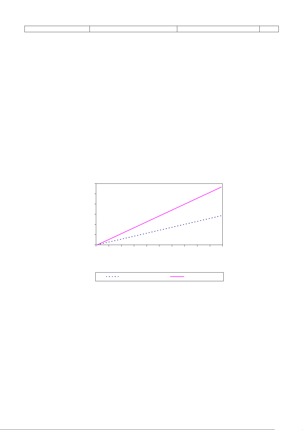
Filter Factor vs Time to Reach New Reading
(for a step change in input signal)
0
20
40
60
80
100
120
0 10 20 30 40 50 60 70 80 90 100
Filter Factor
Time to Reach % of
New Reading (seconds)
90% of New Reading 99% of New Reading
3.3 FILTERING
Frequency fluctuations caused by pulsating flow through a flowmeter can interfere with the precision of the displayed
rate. For this reason, the Model IT375 has a programmable digital filter which will average out these fluctuations and
enable accurate, stable readings.
The degree of filtering of the input signal can be adjusted depending on the magnitude of fluctuation and the particular
application. Values from 1 to 99 can be programmed where 1 corresponds to no filtering and 99 corresponds to
heavy filtering. Such flexibility in filtering allows each application to be addressed on it’s merits.
When programming the degree of filtering, it is advisable to start with no filtering (the factor equals 1) and gradually
increase until a steady reading is obtained. It is important that the filtering is not too heavy because this will cause an
overdamped (slow) response to changes in the flowrate.
The following graph shows the time to reach 90% and 99% of a new reading for a step change in input signal.
Page 9

Sponsler, Inc.
Model IT375
Operation
Pg. 9
3.4 CALCULATION OF RATE
The flow rate, R, is calculated as follows:
f x H
R=
K
where f is the input frequency in Hz (pulses/second).
H is the timebase of rate and is 1 for seconds, 60 for minutes, 3600 for hours and 86,400 for days.
K is the Kfactor (pulses/unit volume).
The Kfactor is flowmeter dependent and is supplied with the flowmeter. It will be either on a calibration certificate or
stamped on the body of the meter.
The user programs the Kfactor and selects the timebase during the programming procedure.
3.5 TOTAL CONVERSION
The Total Conversion Factor is programmed to enable the rate to be displayed in one engineering unit and the totals to
be displayed in another. For example, the rate can be displayed in gallons/minute and the totals in barrels.
The Total Conversion Factor is a division factor which is used to convert the totals to a different engineering unit than
the rate unit. Therefore, it only affects the totals (both resettable and accumulated).
Example:
If the Rate is required in gallons/minute:
1. The Kfactor would be programmed as pulses per gallon.
2. The Timebase would be programmed as minutes.
If the Totals are required in barrels:
1. The Total Conversion Factor is programmed as 42 because there are 42 gallons in a barrel. All totals will now
totalize in barrels.
Below is a table containing common units and their corresponding Total Conversion constants:
Rate/Unit Time Totals
Gallons (US)/Unit Time
Litres/Unit Time Kilolitres 1000
Litres/Unit Time m3 1000
ml/Unit Time Litres 1000
Mgallons/Unit Time Acre-feet 0.32587
Equivalency ≤ 1 rate unit ÷ equivalency
Equivalency ≥ 1 rate unit ÷ reciprocal of equivalency (1/equivalency)
Barrels (oil) 42.000
Total Conversion Factor
Page 10
Sponsler, Inc.
Model IT375
Operation
Pg. 10
Scaling Factor
Out 1
Out 2
Out 3
Out 4
Out 5
Frequency
0
Inp 1
Inp 2
Inp 3
Inp 4
Inp 5
3.6 FREQUENCY CUTOFF
A frequency cutoff can be programmed below which flow rate is not registered.
Input frequencies at or below the cutoff are totalized, however, the rate is displayed as zero.
The frequency cutoff has a default value of 0.25Hz. The cutoff should be left as 0.25Hz unless the flowmeter in use has
a lower frequency.
Note that the lower a cutoff frequency the correspondingly longer response time for flow rate to update. For example, if
the cutoff is set to 0.01Hz the Model IT375 will continue to display the flow rate for 100 seconds even if the signal
stops. This is because a cutoff frequency of 0.01Hz means that the time interval between signals is 100 seconds (period
= 1/frequency), therefore, the Model IT375 must wait 100 seconds before it can determine that the flow has actually
stopped.
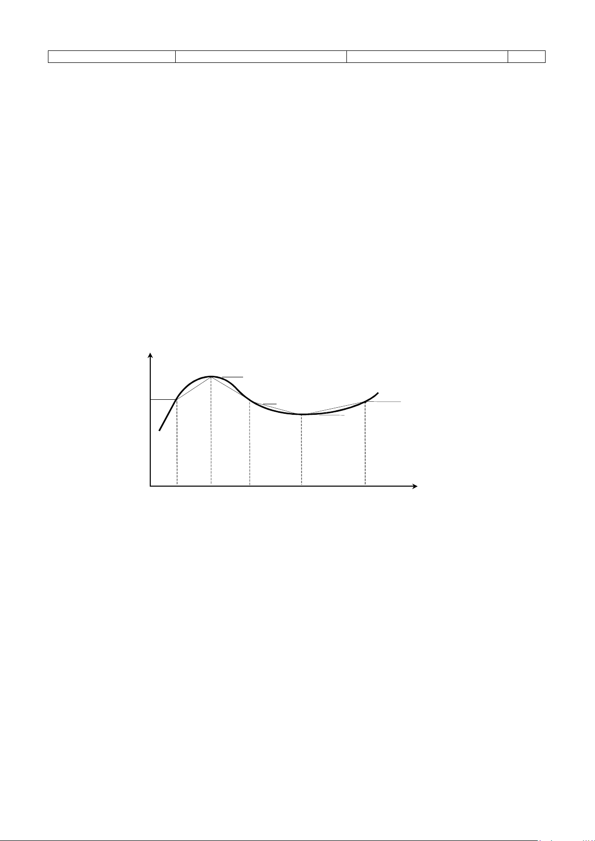
3.7 LINEARIZATION
The following dia gram graphs the change in K-factor with frequency for a hypot hetical flowmeter. The heavy
black line re presents t he actual K-fac tor of t he flowmete r, while the light black line is the a pproximat ion
used i n the instrument.
Up to 10 frequencies and K-factors can be programmed. Frequencies must be programmed in ascending
orde r. L inea r Int er pola tion i s use d be t ween poi nt s. If an i nput fre que nc y is l ess t han t he f irst (l owest) o r
greater than the last (highest) pr ogr ammed frequency, the K-factor will remain a constant value.
Note: Display update time increases to 1sec if the linearizer is enabled in the battery powered version
of the Mod el IT375.
Page 11

Sponsler, Inc.
Model IT375
Programming
Pg. 11
4. PROGR AMMI NG
The Model IT375 is fully programmable with all parameters being stored in non-volatile memory.
The Program Mode can be entered in one of two ways:
1. By removing the lower cover strip (ie. the dark grey strip along the bottom of the enclosure) and reversing it’s left
– right orientation. This brings a small magnet on the inside of the cover strip in contact with a reed switch inside
the instrument.
2. By removing the front section of the enclosure which contains the main processor board and batteries.
The PROGRAM key is used to step through the program (CAL sequences) and the ACCUM TOTAL and RESET keys
on the front panel are used to change and increment the flashing digits.
Note that only flashing digits can be changed.
Up to eighteen CAL steps are accessible depending on which options are installed. The CAL number is displayed in the
lower right display and the parameter is displayed above it.
Parameters in Program Mode that consist of whole numbers and digits after the decimal point are restricted to a
maximum of 6 digits combined. Therefore, the number of significant digits entered as whole numbers will determine the
number of available digits after the decimal point.
Example:
The entry of 1, 100 and 10,000
000001 in the whole numbers leaves 5 digits available after the decimal point
000100 in the whole numbers leaves 3 digits available after the decimal point
010000 in the whole numbers leaves 1 digit available after the decimal point
Page 12

Sponsler, Inc.
Model IT375
Programming
Pg. 12
Step
Comment
CAL 00
Pulse Output (applies to DC Power/Alarm version only).
0 = No pulse output, low and high alarms.
CAL 01
Kfactor - whole numbers.
CAL 02
Kfactor - digits after the decimal point.
The Kfactor is the pulses per unit of measure (eg. pulses/litre,
CAL 03
Cutoff Frequency.
This determines the cutoff frequency in the range of 0.01 -
ken when programming this value
CAL 04
Decimal Point for Rate Display.
The flow rate can be displayed with 0, 1, 2 or 3 places after the
CAL 05
Timebase for Rate.
The rate can be displayed in units per second, minute, hour or
CAL 06
Filter.
The filter constant for filtering the input signal.
CAL 07
Decimal Point for Total Display.
The totals can be displayed with 0, 1, 2 or 3 places after the
CAL 08
Total Conversion Factor - whole numbers.
CAL 09
Total Conversion Factor - digits after the decimal point.
CAL 10
Low Alarm - whole numbers.
CAL 11
Low Alarm - digits after the decimal point.
4.1 PROGRAM STEPS
1 = Scaled pulse output and low alarm.
2 = Unscaled pulse output and low alarm.
pulses/gallon, etc). The Kfactor can be programmed in the
range of 0.000001 - 999,999.
See Section 3.4.
0.99Hz. The default setting is 0.25HZ.
Note that care must be ta
because a low value may cause a slow update time.
decimal point.
day.
0 = second
1 = minute
2 = hour
3 = day
1 No filtering.
to
99 Very heavy filtering.
decimal point.
Page 13

Sponsler, Inc.
Model IT375
Programming
Pg. 13
Step
Comment
CAL 10 & 11 program the flow rate below which the low
CAL 12
High Alarm or Pulse Output Factor - whole numbers.
CAL 13
High Alarm or Pulse Output Factor - digits after the decimal
CAL 12 & 13 program the flow rate above which the high
CAL 14
4mA Setpoint- whole numbers.
CAL 15
4mA Setpoint- digits after the decimal point.
CAL 14 to CAL 15 represent the flow rate at which 4mA will
CAL 16
20mA Setpoint- whole numbers.
CAL 17
20mA Setpoint- digits after the decimal point.
CAL 16 & 17 represent the flow rate at which 20mA will be
CAL 18
Number of linearization points.
00 = linearizer disabled
INP 01
Point #1 Frequency – whole numbers.
Input points must be programmed in ascending frequency
INP.01
Point #1 Frequency – digits after the decicmal
OUT 01
Point #1 Kfactor – whole numbers.
Kfactors can never be zero
OUT.01
Point #1 Kfactor – digits after the decimal.
SOFT
Software Version.
alarm relay will close. The value can be programmed in the
range 0 to 999,999.
point.
alarm relay will close. The value can be programmed in the
range 0 to 999,999.
If the scaled pulse output is selected (CAL0 = 1), then the
value will represent the total per pulse, eg. 5 liters per pulse.
be output. If the 4-20mA output is not installed, these
parameters can be ignored.
output. If the 4-20mA output is not installed, these parameters
can be ignored.
xx = number of points
order
Page 14

Sponsler, Inc.
Model IT375
Programming
Pg. 14
0 = SECOND, 1 = MINUTE, 2 = HOUR, 3 = DAY
RATE TIMEBASE
0
PROGRAM
PRESS KEY TO INCREMENT FLASHING DIGIT
0
3
TOT AL D I SPLAY
PRESS KEY TO INCREMENT FLASHING DIGIT
0
3
K-FACTOR
PROGRAMMING
1468523
0
K-FACTOR
PROGRAM
PROGRAM
PRESS KEY TO INCREMENT FLASHING DIGIT
0-999999
CUTOFF
000
PROGRAM
PRESS KEY TO INCREMENT FLASHING DIGIT
.0.01 - .99 HZ DEFAULT @2.5 HZ
RATE DISPLAY
PROGRAM
0
3
FILTER
1
TOTAL CONVERSION
PRESS KEY TO INCREMENT FLASHING DIGIT
0 - 999999
PROGRAM
.000001 - .999999
PRESS KEY TO INCREMENT FLASHING DIGIT
0 - 999999
PROGRAM
PRESS KEY TO INCREMENT FLASHING DIGIT
.000001 - .999999
LOW ALARM
FLASHING DIGIT
1 - 999999
.000001 - .999999
INITIATE – REMOVE & REVERSE BOTTOM STRIP
EXIT – REPEAT ABOVE STEP
TOTAL
RATE 79.4
0 =
PULSE OUTPUT
WHOLE NUMBERS
DIGITS AFTER DECIMAL
FREQUENCY
PLACES AFTER DECIMAL
1
2
0
CAL 00
000000
CAL 01
000000
CAL 02
PROGRAM
CAL 03
1
2
1
2
99
PROGRAM
0
CAL 04
CAL 05
01
CAL 06
PRESS KEY TO INCREMENT FLASHING DIGIT
PRESS PROGRAM TO ADVANCE TO NEXT MENU ITEM
SOFT
PRESS KEY TO ADVANCE TO NEXT DIGIT
PRESS PROGRAM TO ADVANCE TO NEXT MENU ITEM
PRESS KEY TO INCREMENT FLASHING DIGIT
PRESS KEY TO ADVANCE TO NEXT DIGIT
PRESS PROGRAM TO ADVANCE TO NEXT MENU ITEM
PRESS KEY TO ADVANCE TO NEXT DIGIT
PRESS PROGRAM TO ADVANCE TO NEXT MENU ITEM
PRESS KEY TO INCREMENT FLASHING DIGIT
PRESS PROGRAM TO ADVANCE TO NEXT MENU ITEM
PRESS PROGRAM TO ADVANCE TO NEXT MENU ITEM
PRESS KEY TO INCREMENT FLASHING DIGIT
PRESS KEY TO ADVANCE TO NEXT DIGIT
PRESS PROGRAM TO ADVANCE TO NEXT MENU ITEM
0 = NO OUT PUTS
1 = SCALED PULSE OUTPUT & LOW ALARM
2 = UNSCALED PULSE OUTPUT & LOW ALARM
.000001 - .999999
COMBINATION
CAN’T EXCEED
6 D IGITS
PLACES AFTER DECIM AL
TOTAL CONVERSION
FACTOR WHOLE NUMBERS
DIGITS AFTER DECIMAL
LOW ALARM
WHOLE NUMBERS
DIGITS AFTER DECIMAL
CAL 07
000000
CAL 08
000000
CAL 09
000000
CAL 10
000000
CAL 11
0
PRESS PROGRAM TO ADVANCE TO NEXT MENU ITEM
PRESS KEY TO ADVANCE TO NEXT DIGIT
PRESS PROGRAM TO ADVANCE TO NEXT MENU ITEM
PRESS KEY TO INCREMENT FLASHING DIGIT
PRESS KEY TO ADVANCE TO NEXT DIGIT
PRESS PROGRAM TO ADVANCE TO NEXT MENU ITEM
PRESS KEY TO ADVANCE TO NEXT DIGIT
PRESS PROGRAM TO ADVANCE TO NEXT MENU ITEM
PRESS KEY TO ADVANCE TO NEXT D IGIT
PRESS PROGRAM TO ADVANCE TO NEXT MENU ITEM
1
2
PROGRAM
PROGRAM
PROGRAM
CONTINUED ON NEXT PAGE
COMBINATION
CAN’T EXCEED
6 D IGITS
COMBINATION
CAN’T EXCEED
6 D IGITS
Page 15

Sponsler, Inc.
Model IT375
Programming
Pg. 15
FLASHING DIGIT
CONTINUED FROM PREVIOUS PAGE
HIGH ALARM OR
PROGRAM
PRESS KEY TO INCREMENT FLASHING DIGIT
.000001 - .999999
COMBINATION
4mA SETPOINT
PROGRAM
4mA SETPOINT
PROGRAM
PRESS KEY TO INCREMENT FLASHING DIGIT
20mA SETPOI NT
PROGRAM
PRESS KEY TO INCREMENT FLASHING DIGIT
00
LINEARIZATION
00
PROGRAM
PRESS KEY TO INCREMENT FLASHING DIGIT
POINT #1 FREQUENCY
COMBINATION
PROGRAM
PRESS KEY TO INCREMENT FLASHING DIGIT
0 - 999999
PROGRAM
PRESS KEY TO INCREMENT FLASHING DIGIT
.000001 - .999999
COMBINATION
PROGRAM
PRESS KEY TO INCREMENT FLASHING DIGIT
.000001 - .999999
POINT #1 K-FACTOR
POINT #1 K-FACTOR
COMBINATION
0 - 999999
.000001 - .999999
0-999999
.000001 - .999999
COMBINATION
000000
00 = LINEARIZED DISABLED
SOFT
PROGRAM
SOFTWARE VERSION
CAL 00
PULSE OUTPUT F ACTOR
WHOLE NUMBERS
HIGH ALARM OR
PULSE OUTPUT F ACTOR
DIGITS AFTER DECIMAL
WHOLE NUMBERS
DIGITS AFTER DECIMAL
WHOLE NUMBERS
0 =
CAL 12
000000
000000
CAL 13
PROGRAM
000000
CAL 14
000000
CAL 15
CAL 16
PRESS KEY TO INCREMENT FLASHING DIGIT
PRESS KEY TO ADVANCE TO NEXT DIGIT
PRESS PROGRAM TO ADVANCE TO NEXT MENU ITEM
PRESS KEY TO ADVANCE TO NEXT DIGIT
PRESS PROGRAM TO ADVANCE TO NEXT MENU ITEM
PRESS KEY TO INCREMENT FLASHING DIGIT
PRESS KEY TO ADVANCE TO NEXT DIGIT
PRESS PROGRAM TO ADVANCE TO NEXT MENU ITEM
PRESS KEY TO ADVANCE TO NEXT D IGIT
PRESS PROGRAM TO ADVANCE TO NEXT MENU ITEM
PRESS KEY TO INCREMENT FLASHING DIGIT
PRESS KEY TO ADVANCE TO NEXT DIGIT
PRESS PROGRAM TO ADVANCE TO NEXT MENU ITEM
0-999999
CAN’T EXCEED
6 D IGITS
CAN’T EXCEED
6 D IGITS
CAN’T EXCEED
6 D IGITS
20mA SETPOI NT
DIGITS AFTER DECIMAL
POINTS
WHOLE NUM BERS
POINT #1 FREQUENCY
DIGITS AFTER DECIMAL
WHOLE NUMBERS
DIGITS AFTER DECIMAL
000000
CAL 17
PROGRAM
10
XX
CAL 18
00
000000
INP 01
000000
INPUT 01
000000
OUT 01
000000
OUT 01
PROGRAM
PRESS KEY TO ADVANCE TO NEXT DIGIT
PRESS PROGRAM TO ADVANCE TO NEXT MENU ITEM
PRESS KEY TO ADVANCE TO NEXT DIGIT
PRESS PROGRAM TO ADVANCE TO NEXT MENU ITEM
PRESS KEY TO ADVANCE TO NEXT DIGIT
PRESS PROGRAM TO ADVANCE TO NEXT MENU ITEM
PRESS KEY TO ADVANCE TO NEXT DIGIT
PRESS PROGRAM TO ADVANCE TO NEXT MENU ITEM
PRESS KEY TO INCREMENT FLASHING DIGIT
PRESS KEY TO ADVANCE TO NEXT DIGIT
PRESS PROGRAM TO ADVANCE TO NEXT MENU ITEM
PRESS KEY TO ADVANCE TO NEXT DIGIT
PRESS PROGRAM TO ADVANCE TO NEXT MENU ITEM
XX = NUMBER O F POINTS
0 - 999999
CAN’T EXCEED
6 D IGITS
CAN’T EXCEED
6 D IGITS
202d3.2L
Page 16

Sponsler, Inc.
Model IT375
Example
Pg. 16
Value of
CAL00
0
No Pulse Output
CAL01
000148
Kfactor (whole numbers)
CAL02
914
Kfactor (decimals)
CAL03
0.25
Cutoff Frequency
CAL04
1
Rate decimal position
CAL05
1
Timebase
CAL06
01
Filter disabled
CAL07
0
Total decimal position
CAL08
000000
Total Conversion (whole numbers)
CAL09
264201
Total Conversion (decimals) (1/3.785)
CAL10
000015
Low Alarm (whole numbers)
CAL11
0000
Low Alarm (decimals)
CAL12
000225
High Al arm (whole numbers)
CAL13
000
Hi gh Ala rm (de c imals)
CAL14
000015
4mA Output (whole numbers)
CAL15
0000
4mA Output (decimals)
CAL16
000225
20mA Output (whole numbers)
CAL17
000
20mA Output (decimals)
CAL18
3
3 point linearization
INP 01
000037
Point #01 frequency (whole numbers)
INP.01
0746
Point #01 frequency (decimals)
OUT 01
000148
Point #01 Kfactor (whole numbers)
OUT.01
085
Point #01 Kfactor (decimals)
INP 02
000268
Point #02 frequency (whole numbers)
INP.02
338
Point #02 frequency (decimals)
OUT 02
000148
Point #02 Kfactor (whole numbers)
OUT.02
073
Point #02 Kfactor (decimals)
INP 03
000563
Point #03 frequency (whole numbers)
INP.03
061
Point #03 frequency (decimals)
OUT 03
000148
Point #03 Kfactor (whole numbers)
OUT.03
080
Point #03 Kfactor (decimals)
SOFT
202d3.2L
Software Version
5. EXAMPLE
A typical 2 inch liquid flowmeter has an operating range of 15 – 225 gpm and produces 148.914 pulses per gallon with a
maximum output frequenc y of 563Hz. 3 points of linearization is required. The flow rate is displayed in gallons/ min
with 1 decimal point and the total i n liters wi th no decimals. A 4-20mA output is installed and 4mA is to represent 15
gallons/min and 20mA is to represent 225 gallons/min The instrument is then programmed as follows:
Calibration mode i s entered by removing the lower cover strip (ie. the dark grey strip along the bottom of the enclosure)
and reversing it’s left right orientation.
The following values are then entered:
Step
Parameter
Description
Page 17

Sponsler, Inc.
Model IT375
Versions
Pg. 17
6. VER SIONS
This table summarizes features of each of the different Model IT375 versions:
Model Number IT375i.X0L IT375i.X3L IT375i.X4L
Version
Power
Output
Supply Backup
The standard unit is intrinsically safe (i), turbine mounted (4), battery powered (0) and linearized (L)
X denotes the mounting options, insert the corresponding number for the preferred option:
SR Strain relief cable entry
PM Panel mount
WM Wall mount (standard)
4 Turbine adaptor
EX Explosion proof
Battery powered DC powered Loop powered
DC powered;
Lithium batteries
None
None Lithium batteries Lithium batteries
9-28Volts at
4mA maximum
Alarms - two open collector outputs
Pulse output and low flow alarm
IT375i.40L
Loop powered;
9-28 Volts with
4-20mA out
OR
6.1 BATTERY POWERED VERSION
The battery powered version of the Model IT375 is designed for operation in the field without external power sources.
Lithium batteries provide sufficient power to operate the instrument for up to 5 years and the operator is warned of a low
power condition by a message on the LCD display.
New batteries can be purchased via Sponsler Company, Inc. or our distributors and replaced in the field without
compromising the IS approvals. There are two battery packs in each instrument and care must be taken to replace
only one pack at a time so that there is always power connected to the memory. Failure to do this may result in
loss of totals.
Page 18

Sponsler, Inc.
Model IT375
Versions
Pg. 18
Power/4-20mA Loop
Low
Alarm
Opto-
Isolated
Outputs
High
Alarm
4 +
3 -
6 +
5 -
2 +
1 -
A
-
+
mA Me t er
+
-
RL
For
Pulse
Low Alarm
<<
<<
<<
<<
High Alar m
9 - 28 VDC
4-20mA
6.2 DC POWER VERSION
The DC power version will operate from an external power source between 9-28VDC and draws no more than 4mA.
This enables the instrument to be powered from AC mains with DC adaptors and eliminates the need to run separate DC
voltages in the field.
The instrument uses lithium batteries for backup if the DC power is interrupted. However, alarms and/or pulse outputs
are disabled if the DC power is interrupted.
Open collector outputs are also provided for high and low flow rate alarms. If a pulse output is programmed, terminals
5(-) and 6(+) will act as a pulse out. The output can sink up to 200mA and can be used to control external relays, lights
or audible alarms. The outputs are internally protected against inductive voltage spikes caused by relay coils etc. Both
outputs are independent and optically isolated.
The alarm setpoints can be programmed. The low flow alarm will switch on whenever the flow rate drops below the
programmed low flow rate setpoint. Similarly, the high alarm switches on whenever the flow exceeds the high flow rate
setpoint.
If a scaled pulse output is programmed, a pulse will be output every preset value of the total. For example, if the total is
in liters, then programming 5 will output one pulse every 5 liters. If an unscaled pulse output is programmed, output
pulses will occur at the flowmeter input frequency.
Specification for Alarm Outputs
Maximum Current): 200mA. (sink)
Maximum Voltage: 30Vdc.
Saturation Voltage: 0.8Vdc across outputs when in the "on" state.
Isolation: Both outputs are separately isolated.
Pulse Frequency: 500Hz maxi mum.
Pulse Duration: 1ms if CAL0 = 2 (unscaled pulse output).
If CAL0 = 1 (scaled pulse output) the duration of the pulse automat ically adjusts to the
output frequency:
a. 1ms if output > 50Hz.
b. 10ms if output = 5...50Hz.
c. 100ms if output < 5Hz.
Page 19

Sponsler, Inc.
Model IT375
Versions
Pg. 19
6.3 RELAY AND 4-2 0 mA OUTP UT VERSION
This version combines features of the DC powered with a 4-20mA output.
The 4-20mA output provides a two-wire retransmission of the flow rate. Both the 4mA and 20mA setpoints are fully
programmable so that the output can span either the entire operating range or only a portion.
The instrument draws its operating power from the 4-20mA loop and uses the internal lithium batteries for backup if the
4-20mA loop is interrupted. The alarm/pulse outputs are disabled if the 4-20mA loop is interrupted.
Specifications:
Resolution and Linearity: 0.05% of span.
Accuracy: 0.05% of span at 25°C.
0.1% (typ) of span, full temperature range.
Response (4-20mA): 0.5 second.
Loop Power Supply: 9-28 Volts.
Since the 4-20mA output is designed to provide power to the Model IT375, it is not isolated from the input. Hence, all
sensors must be self-powering (such as reed switches and coils). If external power is required to power the sensor (eg.
Namur switches, Hall effect sensors or opto-sensors), the power supply delivering the external power must be isolated
from the 4-20mA loop supply.
Typical Connection
Connection to a Sensor requiring External Power
Page 20

Sponsler, Inc.
Model IT375
Fl owmeter Inp ut
Pg. 20
7. FLOWMETER INPUT
The Model IT375 has an input conditioning circuit which will accept signals from most sinewave or pulse producing
flowmeters. Links on the rear panel enable the input circuit to be configured for different signal types.
The input will interface directly to:
Turbine flowmeters.
Open collector outputs.
Reed switches.
Logic signals.
Two-wire proximity switches.
The following pages give examples of interfacing to various signal inputs. A circuit diagram of the input is also
provided.
For pulse or logic type signals, the input switching threshold is 1.3 volts. That is, the input signal must have a "low"
voltage of less than 1.2 volts and a "high" voltage of greater than 1.4 volts.
For flowmeters with reluctance type coils, the minimum input voltage is 15mVp-p
All inputs are protected for overvoltage up to 28 volts.
Page 21

Sponsler, Inc.
Model IT375
Fl owmeter Inp ut
Pg. 21
Link 3
COIL PULSE
NPS
Switching threshold voltage is 1.3 volts.
Link Settings
Link 1
Link 2
DBL DBH
NPS
Link 1
Link 2
COIL PULSE
DBL DBH
eg. Positive displa c eme nt flowmeters
Link 1
Link 2
COIL PULSE
DBL DBH
NPS
1. Squarewave, CMOS or Pulse
Link Settings
Link 1
Link 2
DB DBH
2. Open Collector
With 15µA/150µA i nternal pull up current
COIL PULSE
Link 3
3. Reed Switch - Battery Powered
With 15µA internal pull up current
Link Settings
Link 3
NPS
with reed switc h outputs.
Note: For a s witch or reed input with co ntact bounce li nk DBL ca n be switc hed "on". T his will elimi nate the effect o f switch bounce while
limiting the input frequency to 200Hz.
4. Reed Switch - External DC Power
With 150µA internal pull up current
Link Settings
Link 3
Note: For a switch or reed input with contact bounce link DBH can be switched "on". This will eliminate the effect of switch bounce while
limiting the input frequency to 200Hz.
Page 22

Sponsler, Inc.
Model IT375
Fl owmeter Inp ut
Pg. 22
COIL PULSE
DB DBH
NPS
825R inpu t impe dance
Link Settings
Link 1
Link 2
DBL DBH
NPS
Link Settings
Link 1
Link 2
Link 3
COIL PULSE
NPS
825R input impedance
Link Settings
Link 3
COIL PULSE
NPS
825R input impeda nc e
8+
7-
+12 Volt s
0 V
5. Coils
Link Settings
Link 1
Link 2
Link 3
eg. Millivolt signal from paddlewheel
or turbine (15mV P-P minimum).
Note: I f the input has a very high impe danc e ,
the follow ing link setti ngs should be use d:
COIL PULSE
Link 3
6. Namur Proximity Switch
DBL DBH
Note: If a 4-20mA output is installe d, t he suppl y to the proximity switch must be isolated.
For IS connections of Namur switches
see Section 8.
7. Namur Proximity Swith – External DC Power
Note: Use this connection for battery or loop powered versions of the Model IT375.
If a 4-20mA output is installed, the supply to the proximity s witch must be isolated.
Link 1
Link 2
DBL DBH
For IS connections of Namur switches
see Section 8.
Page 23

Sponsler, Inc.
Model IT375
Intrinsic Safety
Pg. 23
8. INTRINSIC SAFETY CONNECTIONS
When installing the Model IT375 in hazardous areas, the wiring and installation must comply with appropriate
installation standards.
The approval uses entity parameters on the input for connections to the flowmeter and associated apparatus type approval
for the 4-20 mA output. The 4-20mA output must, therefore, only be connected to barriers with the specified safety
parameters as shown on the following page.
8.1 COILS
The Model IT375 will connect directly to a turbine flowmeter or paddlewheel with a certified Intrinsically Safe (IS) coil
or other certified IS sensor which produce a pulse input provided they do not exceed the following input parameters:
Ui = 24V
Ii = 20mA
Pi = 320mW
The maximum allowed capacitance and inductance of the pulse or coil including the cabling is:
Cext = 60µF
Lext = 1.5H
The interna l capa cit ance and i nduct ance of the Model IT375 seen on the input are negligibly small with Ci = 0.002uF
and Li = 0mH. The maximum voltage and current produced by the Model IT375 on its inputs (terminals 1 to 4) are:
Uo = 10.0V (open circuit)
Io = 9.0mA (short circuit)
8.2 SIMPLE APPARATUS
Devices such as reed switches which can be classed as "simple apparatus", as defined in the CENELEC standards
EN50020, can be connected to the Model IT375 without certification.
8.3 NAMUR PROXIMITY SWITCHES
Connection to certified Namur proximity switches is permitted as shown on the following page with the following
maximum input parameters:
Ui = 24V
Ii = 20mA
Pi = 320mW
Page 24

Sponsler, Inc.
Model IT375
Intrinsic Safety
Pg. 24
MODEL IT375
+ - 2+
1-
8+
7-
IS BARRIER
Input Parameters
ENTITY PARAMETERS FOR INPUT
Ui = 24 V
Uo = 10.0 V
SAFE AREA
HAZARDOUS AREA
+ - I
Namur Proximity Detector
IS CERTIFIED BARRIER
A Namur Switch Input
MODEL IT375
SAFE AREA
HAZARDOUS AREA
Link Setti ngs
Link 1
Link 2
Link 3
COIL
PULSE
DBL DBH
NPS
8+
7-
IS Barrie r
Ro = 3 00 ohm
Uo = 28 V maximum
Io = 9 3 m A maximum
Po = 0.653 W maximum
L/R < specified for selected barrier
EXAMPLES BARRIERS
MTL 187’ 787, 787SP, 3041, 3042,
2441, 2442, 4041, 4045
Pepperl & Fuchs
Z248/Ex, Z488/Ex, Z488/Ex-R,
KHD3-ICR/E X 13 0 20 0, ZG 31/EX
Cable length < 5 km
Rate Totalizer
TER M INALS 7 & 8
Ii = 20 mA
Pi = 320 mW
Ci = 0.002 uF
Li = 0.0
Io = 9.0 mA
Cext = 60 uF
Lext = 1.5 H
Uo = 24 V maximum
Io = 2 0 m A maximum
Po = 320 mW maximum
L/R < specified for selected barrier
And 4-20mA Retransmission
IS Certified
INPUT
Page 25

Sponsler, Inc.
Model IT375
Intrinsic Safety
Pg. 25
IS CERTIFIED BARRIER
SAFE AREA
HAZARDOUS AREA
4 or 6
3 or 5
MODEL IT375
IS Certified Device
8.4 ALARM OUTPUTS
The low alarm and high alarm/pulse output can be connected to suitably certified devices provided the circuit is protected
with a barrier with the maximum safety parameters:
Uo = 28V
Io = 93mA
Pmax = 0.653W
The input capacitance on these terminals is 0.1uF max and the inductance is negligible.
Note: The two alar m outputs must be kept as independent IS circuits and each protected with their own barrier. It i s not
permissible to connect these circuits via a common barrier.
Uo = 28 V maximum
Io = 9 3 m A maximum
Po = 653 mW maximum
Such as an Alarm Lamp
Or IS Solenoid
Page 26

Sponsler, Inc.
Model IT375
Installation
Pg. 26
MODEL IT375
SIGNAL
HIGH
LOW
9-28v
9. INSTALLATION
9.1 WALL MOUNTING
A wall mounting bracket is supplied with each instrument. Round head screws should be used to attach the bracket to the
wall (countersunk screws should not be used). The bracket is mounted first with the tray section at the bottom. The
instrument is then mounted on the bracket with two screws as shown below.
9.2 PANEL MOUNT VERSION
The panel mount version of the Model IT375 is supplied with two panel mount brackets and plug-in terminals which are
accessible from the rear of the instrument.
A diagram of the rear panel is shown below:
ALARM
RELAY 2
ALARM
(PULSE)
INP UT
(INPUT )
RELAY !
POWER/4-20 !mA OUTPUT LOOP
Rear View of IT375 Panel Mount Case
The cutout for the panel mount version is 141mm (5.55") wide x 87mm (3.43") high.
Page 27

Sponsler, Inc.
Model IT375
Installation
Pg. 27
9.3 REMOVING THE FRON T PANEL
The front panel should be removed as follows:
1. Remove the top and bottom cover strips (ie. the dark plastic strip) by levering a screwdriver under one end.
2. Undo the screws retaining the front. Do not remove the screws, they are retained by O-rings.
3. Remove the front panel from the housing.
To replace the front cover, reverse the above procedure. Ensure that the front panel is aligned at connector points before
tightening the screws.
9.4 THE MAIN ELECTRONICS
The front section of the housing contains the microprocessor and display. It is possible to adjust the display contrast via
a small potentiometer on the board. The Display Contrast is shown below and this can be adjusted for optimum contrast
and clarity.
Adjacent to this control is a RESET switch which can be used to reset the microprocessor.
Note: Depressing the RESET switch will reset all totals to zero.
Page 28

Sponsler, Inc.
Model IT375
Installation
Pg. 28
152mm (6.0")
98mm (3.9")
141mm (5.6")
87mm (3.5"
43mm (1.7")
16mm (0.6")
REAR VIEW
SIDE VIEW
Terminal Descriptions
Dimensional Dr awing
All Versions
No.
7
8
Signal Input (-)
Signal Input (+)
4-20mA (-) or OVdc In
11
4-20mA (+) or +9-28Vdc In
2
4-20mA or DC Versions
No.
3
4
Low Alarm (-)
Low Alarm (+)
5
6
High Alarm (-) or Pulse (-)
High Alarm (+) or Pulse (+)
9.5 WIRING
When connecting the IT375 it is good practice to use shielded cable. The shield should be connected to earth at one end
of the cable. The other end of the shield should not be connected.
This wiring practice is mandatory in order to comply with the requirements for Electromagnetic Compatibility as per
EMC-Directive 89/336/EEC of the Council of the European Community
.
9.6 TERMINAL DESIGNATIONS
All versions
8 Pulse (+) / Coil Input
7 Pulse (-) / Coil Input
4-20mA and DC Versions
6 High Alarm (+) or Pulse Output (+)
5 Hi gh Ala rm (-) or Pulse Output (-)
4 Low Alarm (+)
3 Lo w Al arm (-)
4-20mA Output Version
2 4-20mA (+)
1 4-20mA (-)
DC Power Version
2 DC Power (+) +9 to 28V
1 DC Power (-) 0V
Page 29

Sponsler, Inc.
Model IT375
Installation
Pg. 29
Index
4-20mA Output, 19
A
Accumulated Total, 9
Operating
Temperature, 6
Operation, 7
P
Panel Mount, 6,26
Programming, 11
Protection, 6
Pulse Output, 12
B
Battery Powered, 17
C
CAL Sequences, 12
Cutoff Frequency, 11
D
DC Power, 18
Decimal Point, 12
Display, 7
Display Test, 7
F
Filtering, 8
Flow Chart, 14,15
Flow Rate, 9
Frequency Cutoff, 10
H
High Alarm, 13
High Test, 7
R
Rate, 9
Removing the Front Panel, 27
Resettable Total, 7
S
Specification, 6
T
Temperature, 6
Terminal
Designations, 26, 28
Test Mode, 7
Timebase, 12
Total Conversion, 9
W
Wall Mounting, 26
I
Input Signal, 18
Installation, 26
Intrinsic Safety, 5, 23
K
Kfactor, 9,12
L
Link Settings, 19
Low Alarm, 12
Low Test, 7
M
Model Number, 4
O
Page 30

Sponsler Company, Inc.
Model IT375
Index
Pg. 30
Page 31

Sponsler Company, Inc.
Model IT375
Index
Pg. 31
Page 32

© 20 09
Pub. No. MN-IT375
(9/2009)
 Loading...