

Page 1

Page 2

SPECIFICATIONS
S
E
Description
Featuring 4
battery powered indicator capable of accepting magnetic
pickup, DC pulse and switch closure inputs. The unit provides a
loop powered 4-20mA output. The IT 300N uses the 4-20mA
loop to provide power when this output is used.
Specifications
POWER:
BATTERY POWERED
Supplied with 2 C size Lithium battery pack.
EXTERNAL POWER INPUT
Voltage: 8.5 to 30 VDC
Current: Less than 5 mA
Protection: Reverse Polarity Protection on DC Power Input
LOOP POWERED
Voltage: 8.5 to 30 VDC
Protection: Reverse Polarity Protection on Current Loop
Loop Burden: 8.5V maximum
1/2
digits of rate and 8 digits of total, the IT 300N is a
Battery Life Expectancy
RUN TIME
Idle 2hrs/day 8hrs/day 24hrs/day
IT 300N A 5 yrs 4.5 yrs 3.5 yrs 2.1 yrs
IT 300N A 4 5 yrs 3.7 yrs 2.7 yrs 1.5 yrs
IT 300N B/C
tandby Operation
IT 300N A/B/C 10 years
xternal or Loop Power
PART NUMBER
All of the above values are calculated with the pulse output ON.
Turn the pulse output OFF to prolong battery life up to 30%.
DISPLAY:
Rate Display: (selectable decimal)
4.5 Digits (59999), 0.35" High, Display updates once every
two seconds
Rate Descriptors: /SEC, /MIN, /HR
Min. Input Frequency: 5 Hz (delay of 0.2 seconds)
Totalizer Display: (selectable decimal)
8 Digits (99999999), 0.2" High
Totalizer Descriptors: GAL, LIT, FT3, M3, "blank"
Warning Displays: Low battery warning
PULSE OUTPUT:
The pulse output advances with the least significant digit of
the totalizer or decimal multiples there of (see Pulse output
divider).
Type: Isolated photomos relay
Max. voltage (off state): 30 VDC
Current (on state): 100mA
Pulse Duration: Selectable (see below)
Pulse Output Rate: Selectable (see below)
5 yrs 3.7 yrs 2.7 yrs 1.5 yrs
ACCURACY:
0.01% Reading, ±1 count
Temperature Drift: 50 ppm/°C Worst Case
ENVIRONMENTAL:
-22°F (-30°C) to + 158°F (70°C)
HUMIDITY
0 - 90% Noncondensing
INPUTS:
MAGNETIC PICKUP INPUT
Frequency Range: 0 to 3500 Hz
Trigger Sensitivity: 30 mV p-p
Over Voltage Protected: ± 30 VDC
OPTO-ISOLATED DC PULSE INPUT
High (logic 1): 4-30 VDC
Low (logic 0): Less Than 1 VDC
Minimum Current: .5 mA
Hysteresis: 0.4 VDC
Frequency Range: 0 to 5 kHz
Min. Pulse Width: 0.1 msec
CONTACT CLOSURE INPUT (contact closure to common)
Internal Pullup Resistor: 100 KΩ to +3.6 VDC
High (logic 1): Open or 4-30 VDC
Low (logic 0): Less Than .5 VDC
Internal Switch Debounce Filter: 0 to 40 Hz
CAUTION: Sustained contact closure will shorten
battery life.
RESET INPUT (contact closure to common)
Internal Pullup Resistor: 100 KΩ to +3.6 VDC
High (logic 1): Open or 4-30 VDC
Low (logic 0): Less Than .5 VDC
Minimum On : 25 msec
CAUTION: Sustained contact closure will shorten
battery life.
K-FACTOR
Range: 0.001 to 59999
Decimal Point Locations: XX.XXX to XXXXX
Factor Multiplier: Multiplies entered K-Factor by 1, 10, 100,
1000.
10 Point Linearization Option
This feature allows the user to enter 10 different frequencies
with 10 different corresponding K-Factors to linearize non
linear signals.
ANALOG OUTPUT:
Type: 4-20 mA follows rate display, Two wire hookup
Accuracy: 0.15% Full Scale at 20° C
Temperature Drift:
50 ppm/°C Typical
200 ppm/°C Worst Case
Reverse Polarity Protected
NOTE:The IT 300N uses the 4-20 mA loop power as its power
source when this output is used.
SPEED (HZ) 1248
MOUNTING OPTIONS:
Min. on/off (msec) 500 250 125 62.5
Pulse output divider: User selectable, ÷1, ÷10, ÷100 or OFF
NOTE: Select OFF for max. battery life.
Explosion Proof - Class I, Division I, Groups B, C & D
Class II, Division I, Groups E, F & G
R- Wall Mount - NEMA 4X Enclosure
(unit mounted on cover)
1
Page 3
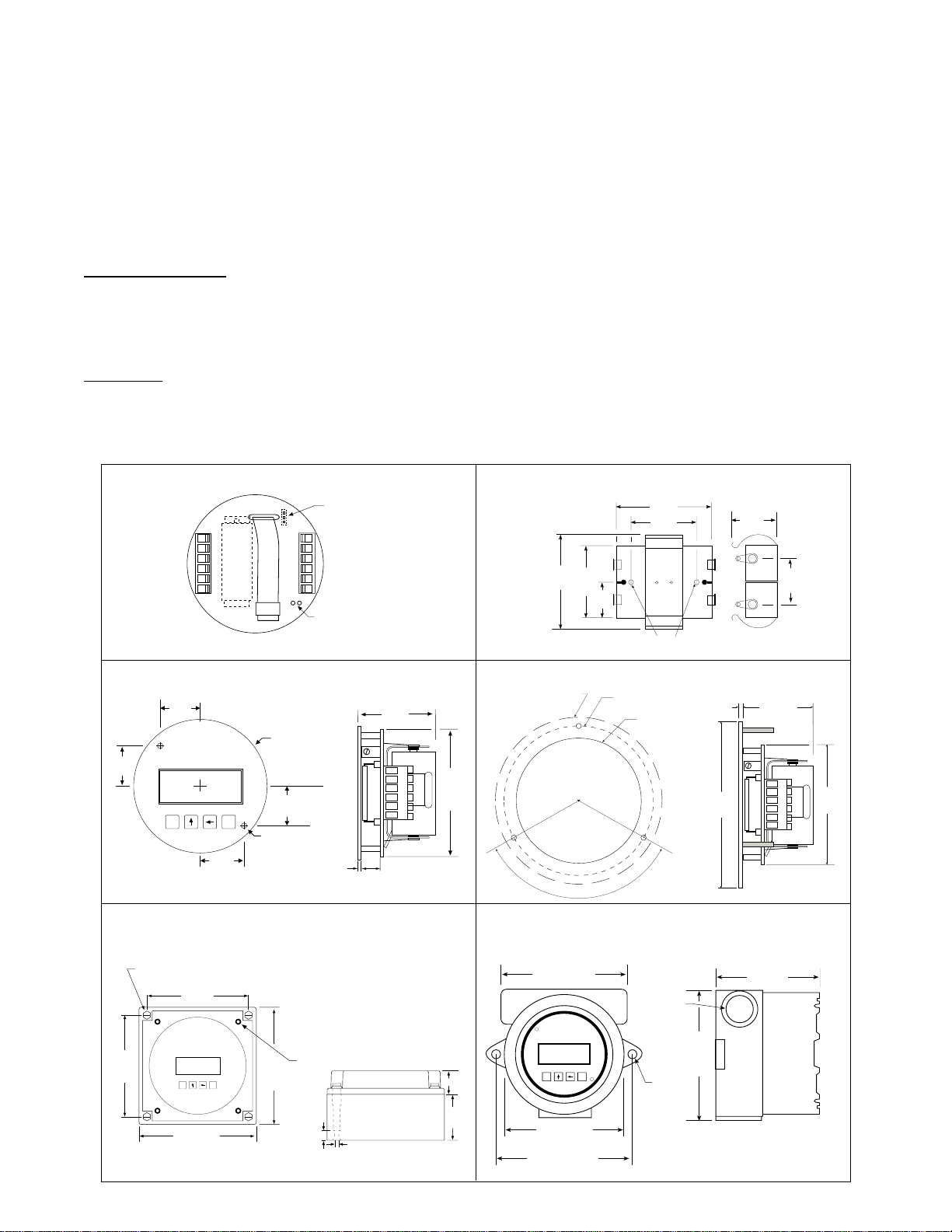
INSTALLATION
Battery Installation and IT 300N Initialization:
All meter mounted IT 300N models are shipped with the batteries installed. When using external BATPACK,
mount within 12" and plug connector into 3 position square posts (see Fig 1). Polarity is not a concern because
center is common. The unit will have to be initialized and operating parameters entered.
CAUTION : All IT 300N models are provided with two or more sources of power. The power should not be
interrupted when changing batteries. For models with two batteries, change one battery at a time. If all power
sources are interrupted, information will be lost and the unit will have to be re-initialized as described below.
To install the battery, begin by locating the battery holder. The IT 300N-2, 3 and 5 require opening the enclosure
cover and removing the IT 300N to expose the battery holder.
The plus terminal of the battery is marked with a (+) symbol stamped into the battery holder. Be sure to install the
battery(ies) correctly.
To Initialize, Locate the “initialize” terminals on the IT 300N PCB (see Fig1). Using a small length of wire, temporarily jumper across the initialize terminals. The unit will respond by showing its software version number and then
illuminating the LCD display. See Programming Flowchart to setup desired operating parameters.
Fig 1
.900
(22.8)
Mounting holes molded
directly under cover screws.
Max. screw head .29"
(Typ. 4 places)
Rear View
789101112
.992
(25.2)
4.21
(107)
.992
(25.2)
M
E
Battery
Mounting holes
.125 Drill (2 places)
.375 Nylon Spacer
Supplied
BATPACK
Connector
6 5 4 3 2 1
Jumper Momentarily
To Initialize
3.0120 DIAMETER
.900
(22.8)
.375
(9.5)
.10
(2.5)
To access terminals,
remove cover and 4 panel
screws. Terminals are on
bottom side of PC board.
1.8
(46)
2.875
(73)
BATPACK
2.093
(53)
1.75
(44.5)
2.125
1.625
(54)
(41)
.812
(20.6)
Mounting
Holes
Outside Dotted Line Shows
Outside Panel Dimension
(4.00" Diameter)
IT300NIT300NR (WALL MOUNT)
To access terminals, unscrew cover and loosen 2 panel screws.
(If screws are removed, spacers may drop out.) Terminals are on
bottom side of PC board.
5.00
(127)
120°
3.582" Dia. Bolt Circle
.125" Holes to be 120° Apart
3.062" (77.77)
Dia. Cutout
3/4 NPT
(2) HLS
.10
(2.54)
4.00
(101.6)
1.10
(28)
4.63
(117)
(43)
1.0
(25.4)
1.7
2.875
(73)
4.21
(107)
PANEL INSTALLED
M
E
4.92
(125)
TOP VIEW
Panel Screws (4 places)
4.92
(125)
.43
(11)
.18
(5)
SIDE VIEW
1.97
(50)
(25)
5.00
(127)
M
.98
E
4.25
(108)
5.25
(133)
5/16
2
Page 4
THEORY OF OPERATION
Flow rate equation: Flow total equation:
Flow Rate Indication =
Input Frequency
FAC x FAC mul
x Time Scaler
Flow Total =
Sum of Input Pulses
FAC x FAC mul
Where Time Scaler is equal to: 1 for rate per second read out
60 for rate per minute read out
3600 for rate per hour read out
10 Point Linearization Option:
A 10 point linearization table is used to construct a curve describing the relationship of K-Factor and input
frequency. The measured input frequency is used to access the table. A linear interpolation of adjacent point pairs
is used to arrive at the K-Factor at that input frequency. The flow rate and total are then computed based upon the
K-Factor for that measurement sample.
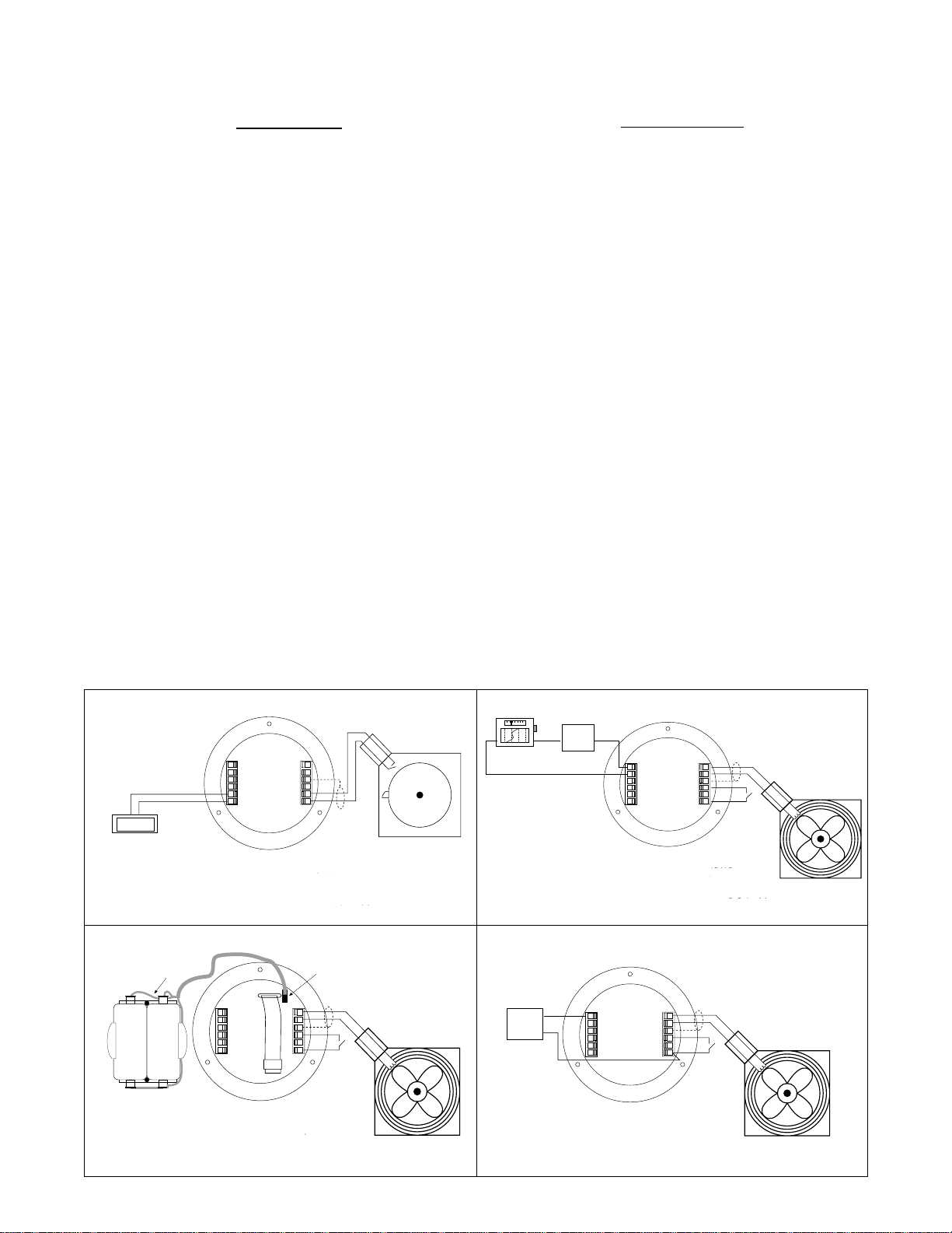
WIRING
Several typical applications of the IT 300N are shown below. Please observe that the various pulse inputs and
power options may be intermixed in many ways to solve common applications. The isolated pulse output may be
freely used so long as proper polarity is observed.
Caution: When 4-20 mA loop is utilized, the power wiring to the loop should always be to terminals (+) 12 and (-)
11. Accidental wiring to (+) 12 and (-)6 should be avoided since excessive current flow may result.
Caution: The magnetic pickup input and contact closure input require isolated sensors for proper operation.
Accidental connections to earth may result in erroneous operation of the analog output and/or excessive
current flow.
Caution: Accidental connections from circuit common (3 or 6) to earth or terminal (11) may result in erroneous
operation of the analog output and/or excessive current flow.
TYPICAL APPLICATIONS
CONTACT INPUT / PULSE OUTPUT / BATTERY POWERED
41
123456
KAL1B
Totalizer
4-20mA (+)/DC In (+) 12
789101112
4-20mA (-) 11
Opto Input (+) 10
Opto Input (-) 9
Opto Out (+) 8
Opto Out (-) 7
654321
1 Mag Input 1
2 Mag Input 2
3 Shield/GND
4 Reset Input
5 Contact Input
6 Common/ DC In (-)
Flowmeter with
Switch Closure Output
MAG INPUT / BATPACK POWERED
BATPACK
789101112
BATPACK PLUGIN
CONNECTOR
6 5 4 3 2 1
Reset Switch
Remote
+
Strip Chart
Recorder
12 VDC
Ext. Battery
Power
Supply
Power
Supply
MAG INPUT / 4-20mA LOOP POWERED
24 VDC
-
-
+
Power
Supply
KEP
115-24
789101112
4-20mA (+)/DC In (+) 12
4-20mA (-) 11
Opto Input (+) 10
Opto Input (-) 9
Opto Out (+) 8
Opto Out (-) 7
1 Mag Input 1
2 Mag Input 2
3 Shield/GND
4 Reset Input
5 Contact Input
6 Common/ DC In (-)
MAG INPUT / DC POWERED
(without 4-20mA Loop Option)
+
-
or
789101112
6 5 4 3 2 1
654321
Remote
Reset Switch
Turbine Meter with
Mag Pickup
4-20mA (+)/DC In (+) 12
4-20mA (-) 11
Opto Input (+) 10
Opto Input (-) 9
Opto Out (+) 8
Opto Out (-) 7
1 Mag Input 1
2 Mag Input 2
3 Shield/GND
4 Reset Input
5 Contact Input
6 Common/ DC In (-)
Turbine Meter with
Mag Pickup
VDC In (+) 12
Do Not Use 11
Opto Input (+) 10
Opto Input (-) 9
Opto Out (+) 8
Opto Out (-) 7
1 Mag Input 1
2 Mag Input 2
3 Shield
4 Reset Input
5 Contact Input
6 VDC In (–)
Turbine Meter with
Mag Pickup
3
Page 5

DEFINITIONS
ent Code
: (enter code) This prompt will only appear if the panel lock is ON. Press the ↑ key to
increment each digit. Press the ← key to step to the next digit to the left. Press the E key to
enter the 4 digit code. If the entered code is correct, the display will advance to the next
menu prompt (CLr tot). If incorrect, the display will return to the run mode.
Clr tot
: (clear total) Clears (resets) the totalizer. Press the E key to clear the total and return to
the run mode. Press the M key to skip and advance to the next menu selection.
FAC nnUl
1000
fdeC
: (factor multiplier) Sets the factor multiplier value. Press the ↑ key to select 1, 10,
. Press the E key to enter the displayed value.
: (factor decimal) Sets the decimal location for the factor. This location is restricted to 3
places (59.999). The use of this decimal automatically limits the number of decimal locations
allowable in the rate and total to acceptable ranges. Press the ← key to move the decimal.
Press the E key to select the displayed decimal location.
faC lInear
linearization option. The
/
10poInt
: (factor type) This prompt will only appear if the unit is ordered with the 10 point
10 poInt
linearization selection is recommended for flow meters
whose K-factors change with different flow rates. This selection allows users to enter up to
10 different frequencies with 10 corresponding K-factors for different flow rates. The
setting is used for flow meters whose output is linear over its' entire operating flow range.
Press the ↑ key to step to the desired choice. Press the E key to enter the displayed factor
type.
100
lInear
,
No / yes set10pt
Select
: (set 10 point?) This prompt allows the user to skip the 10 point setup routine.
yes
for initial setup or to change the present 10 point values. Select
No
to skip and
keep the existing values.
faC
: (factor) This prompt appears on all units with linear inputs. The Factor is the number of
pulses per unit volume for the flow sensor. The pulses/unit volume is implied by the totalizer
descriptor when a descriptor is used. The implied units for the Factor are then as follows:
GAL pulses/gallon
LIT pulses/liter
FT3 pulses/ft3
M3 pulses/M3
Factors from 0.001 to 59999 may be used. A 0 value for the factor is not allowed and a
warning message will be given. The factor is displayed on the subsidiary (lower) display.
Press the ↑ key to increment each digit. Press the ← key to step to the next digit to the left.
Press the E key to enter the displayed factor.
4
Page 6

DEFINITIONS
(continued)
fr#
: (frequency for point #) This prompt will only appear when 10 point selected. It sets the
frequency for each of the 10 points (#). Press the ↑ key to increment each digit. Press the ←
key to step to the next digit to the left. Press the E key to enter the desired frequency for
point #.
faC#
: (factor for point #) This prompt will only appear when 10 point selected. It sets the factor
for each of the 10 points (#). Press the ↑ key to increment each digit. Press the ← key to
step to the next digit to the left. Press the E key to enter the desired factor for point #.
NOTE: The display will advance to the next point (Fr#) after each entry of the Fr & Fac until all 10 points are
complete. entering a 0 in the Fr or fac setting will advance the display to the next menu prompt (tdec).
tdeC
: (totalizer decimal) Sets the decimal location for the totalizer. The totalizer decimal is not
a dummy decimal and will scale the totalizer display accordingly. (i.e. if the tdec is set in the
tenths position (1234567.8), 100 will be displayed as 100.0). The location of the decimal
point allows for greater resolution of both the totalizer display and the pulse output. The
pulse output advances at a rate dependent on the least significant digit of the totalizer. The
totalizer decimal location is restricted to a maximum of 4 places (1234.5678). However, the
number of totalizer decimal locations allowable is reduced with each decimal place added to
the factor decimal. Press the ← key to move the decimal. Press the E key to enter the
displayed decimal location.
Note:
The selection of the factor decimal point limits the available selections
for the number of decimal points available for the totalizer. This is automatic.
Enter your selection of the Factor’s decimal point before entering the totalizer
decimal point to assure the proper selection of the totalizer decimal point has
been made.
tot desC
: (totalizer descriptor) This allows you to illuminate one of the available descriptors on
the display (GAL, LIT, FT3, M3 or "blank"). Press the ↑ key to select the descriptor. Press
the E key to enter the selected descriptor.
sCale
: (ratemeter scaling) Sets the rate readout. Choose rate per hour (
seconds (
seC
). The scale setting is shown on the main (upper) display. Press the ↑ key to
Hrs
), minutes (
step to the desired choice. Press the E key to enter the displayed scale setting.
Note: A rate descriptor corresponding to the above choice will be illuminated on the display.
5
nnIn
) or
Page 7

DEFINITIONS
(continued)
r deCloC
: (ratemeter decimal location) Sets the decimal location for the ratemeter. The
ratemeter decimal is not a dummy decimal and will scale the rate display accordingly. (i.e. if
the r decloc is set in the tenths position (123.4), 100 will be displayed as 100.0). The
ratemeter decimal location is restricted to a maximum of 4 places (.1234). However, the
number of ratemeter decimal locations allowable is reduced with each decimal place added
to the factor decimal. Press the ← key to move the decimal. Press the E key to enter the
displayed decimal location.
Note: The flow rate indicator will flash “59999” if the computed flow rate exceeds the 59999
display capability of the indicator. Choose a new decimal point location to avoid this.
oUt lo
: (out low) Sets the low setting for the 4-20 mA analog output. Key in the low rate value at
which the unit will output 4mA. Press the ↑ key to increment each digit. Press the ← key to
step to the next digit to the left. Press the E key to enter the displayed out lo value.
oUt HI
: (out high) Sets the high setting for the 4-20 mA analog output. Key in the high rate value
at which the unit will output 20 mA. Press the ↑ key to increment each digit. Press the ← key
to step to the next digit to the left. Press the E key to enter the displayed out hi value.
pUlseoUt
count divided by the selected divider. The pulse out can be divided by 1 (
(
d 100
: (pulse out divider) This allows the unit to output a pulse for each least significant total
d 1
), or turned off (
), 10 (
off
). With the divider set at 1, the unit will give a pulse out for every
d 10
increment of the LSD displayed.
Note: For maximum battery life, turn the pulse output off when pulse output is not used.
), 100
Selecting the proper pulse output divider may be needed so that the pulse output
does not exceed the maximum rate of the pulse output (10 Hz). If the pulse output
pulses too quickly a flashing display will result. Pressing the “M” key will result in a
display of an error message “E PULSE”. Press the “E” key to return to the run mode.
FrEQ.OUT
4 or 8 Hz. This menu item is skipped if
loC Code
: (pulse out frequency) Sets the pulse output frequency / duration. Selections are: 1, 2,
pUlseoUt
: (lock code) Sets the 4 digit lock code to be entered when the unit prompts
is turned off.
ent Code
This allows the user to gain access to the menu when the unit is locked. Press the ↑ key to
increment each digit. Press the ← key to step to the next digit to the left. Press the E key to
enter the displayed code.
Record this number for later use!
loC UnIt
: (lock unit) Sets the panel lock ON or OFF. Press the ↑ key to select On or OFF. Press
the E key to enter the displayed selection.
.
6
Page 8

FDEC
RUN MODE
FAC
0000
FAC
0p
F
FaC
000
YES
YES
YES
If panel
lock OFF
RATE
TOTAL
M
If panel
lock ON
Press the M key to enter the programming menu.
If the panel lock is on, you must enter the 4 digit lock code to gain access
to the menu.
ENTER CODE
FACTOR
MULTIPLIER
FACTOR
TYPE
SET 10PT
No
selected
CLEAR TOTAL
FACTOR
DECIMAL
1
lInear
10poInt
selected
No
SET 10PT
1
10
100
1000
oInt
M
ent Code
If code
correct
CLR ToT
1
FAC nnUL
12345678
10poInt
FACTOR
selected
E
E
M
M
M
M
If code
incorrect
lInear
selected
100
M
Press the
key to increment each individual digit of the code.
Press the key to advance to the next digit.
Press the E key to enter the displayed code.
If the code is correct, display advances to "
clr tot
", if not, display returns
to run mode
E
E
E
Press the E key to clear the totalizer and return to the programming menu.
Press the M key to skip and go to next menu item.
Press the key to choose the factor multiplier (1, 10,
100, 1000
).
Press the E key to enter the displayed factor multiplier.
Press the M key to skip and keep the existing factor multiplier.
Press the
key to step the factor decimal to the desired location.
Press the E key to enter the displayed decimal location.
Press the M key to skip and keep the existing location
Press the
E
Press the E key to enter the displayed factor type.
key to choose factor type (
10point
or
linear
).
Press the M key to skip and keep the existing factor type.
The
FAC
prompt will only appear if
linear
is selected or if the unit was
ordered without the 10 point linearization option.
Press the
key to increment each individual digit of the factor.
Press the key to advance to the next digit.
E
Press the E key to enter the displayed factor.
Press the M key to skip and keep the existing factor.
The
SET 10pt
prompt will only appear if
10 point
is selected. This allows
users to bypass the 10 point set up and keep the existing values.
Press the key to choose YES or NO.
Press the E key to enter the displayedselection.
Press the M key to skip (same as selecting NO).
If Fr# = 0
If FAC# = 0
r#
#####
M
#####
M
# = 10
#
E
Press the
key to increment each individual digit of the frequency for
point #.
Press the key to advance to the next digit.
Press the E key to enter the displayed frequency.
Press the M key to skip and keep the existing frequency.
If 0 is entered, the display will advance to the next prompt (tdec).
E
Press the key to increment each individual digit of the factor for point #.
Press the
key to advance to the next digit.
Press the E key to enter the displayed factor.
Press the M key to skip and keep the existing factor.
If 0 is entered, the display will advance to the next prompt (tdec).
7
Page 9

PROGRAMMING FLOWCHART
EC
SEC
0000
59999
SEC
234
0000
yes
Continued From
Previous Page
(continued)
TOTAL DECIMAL
TOTAL
DESCRIPTOR
SCALE
(ratemeter)
RATE DECIMAL
LOCATION
OUT LOW
(4mA)
OUT HIGH
(20mA)
GAL
LIT
FT3
M3
"blank"
NNIN
HRS
TD
12345678
M
ToT DESC
M
SCALE
M
1
R DECLoC
M
oUT Lo
M
oUT HI
M
Press the key to step the totalizer decimal to the desired location.
E
Press the E key to enter the displayed decimal location.
Press the M key to skip and keep the existing location
Press the
E
Press the E key to enter the displayed descriptor.
Press the M key to skip and keep the existing descriptor.
Press the
Press the E key to enter the displayed scale setting.
E
Press the M key to skip and keep the existing setting.
Press the
Press the E key to enter the displayed decimal location.
E
Press the M key to skip and keep the existing location
Press the key to increment each individual digit of the out low setting
(4mA value). This will only display on units with Analog Output.
Press the key to advance to the next digit.
E
Press the E key to enter the displayed value.
Press the M key to skip and keep the existing value.
Press the key to increment each individual digit of the out high setting
E
(20mA value). This will only display on units with Analog Output.
Press the key to advance to the next digit.
Press the E key to enter the displayed value.
Press the M key to skip and keep the existing value.
key to step to the desired totalizer descriptor.
key to step to the desired scale setting.
key to step the ratemeter decimal to the desired location.
DIVIDER
PULSE OUT
PULSE
OUTPUT
FREQUENCY
LOCK
CODE
D 1
D 1
D 10
D 10
D100
D100
oFF
oFF
1 H2
2 H2
4 H2
8 H2
D 1
PULSEoUt
M
1 HZ
freq.out
M
loc code
M
loC UnIt
M
RUN MODE
Press the
E
Press the E key to enter the displayed divider.
Press the M key to skip and keep the existing divider.
Press the
Press the E key to enter the displayed frequency.
E
Press the M key to skip and keep the existing frequency.
This will not display if Pulse Out is turned OFF.
Press the key to increment each individual digit of the lock code.
Press the key to advance to the next digit.
E
Press the E key to enter the displayed value.
Press the M key to skip and keep the existing value.
Press the key to step to the desired lock setting.
Press the E key to enter the displayed lock setting.
E
Press the M key to skip and keep the existing setting.
key to step to the desired divider for the pulse output.
key to step to the desired frequency for the pulse output.
8
Page 10

OPERATION
A suitable pulse producing device or flow meter is wired to one of the three pulse inputs provided on the IT 300N.
Only one of these inputs is used in a given application. There are no connections to the two unused pulse inputs.
Isolated magnetic pickups may be connected to terminals 1 and 2. Isolated contact closures may be connected to
terminals 5 and 6. Any pulse type may be connected to terminals 9(-) and 10(+).
Power to the unit may be provided by internal batteries, external DC, or the current loop. In all cases, the internal
battery will provide for continued operation in the event primary power is lost.
Once properly wired, the operation of the IT 300N is automatic.
The flow totalizer is updated every 2 seconds* with the latest total. If no input counts are received the unit remains
in a low power state to conserve power.
The flow total may be cleared by the front panel switch sequence or by a contact closure on the remote reset
terminal to circuit common.
To reset the unit from the front panel, the following key sequence is required:
Press M “CLr tot” will be displayed (if the panel lock is on, the display will prompt "
Enter the proper code to advance to the
Press E To clear the total. Unit will return to operation
The flow rate indicator will measure the flow rate once every 2 seconds* and display the flow rate.
If the input pulses are not detected within the delay setting (0.2 seconds), a flow rate of 0 will be indicated.
The analog output will be scaled based on the user selected zero and full scale and the measured flow rate. The
analog output is updated every 2 seconds*.
The pulse output will generate a burst of pulses every 2 seconds* in accordance with the instrument setup of pulse
scaling.
MAINTENANCE:
The only scheduled maintenance for the IT 300N is periodic replacement of the battery.
Battery Replacement:
The IT 300N has a battery monitor feature which illuminates when the lithium battery voltage approaches its end
of life. A descriptor, “BAT”, illuminates when the battery voltage falls below this predetermined value. The low
battery detector operates correctly with all power options.
clr tot
ent code
prompt)
".
The battery, or batteries, should be replaced within several weeks of the first occurrence of low battery warning,
“BAT”. Left unattended, the unit may become inaccurate, cease to operate or loose setup information or
malfunction.
Batteries should be replaced one at a time to avoid interrupting the power.
See INSTALLATION section for battery installation instructions.
9
Page 11

ERROR MESSAGES
The IT 300N is provided with extensive self checking which assists the user in the location of setup entry errors
and in reporting malfunctions or unusual operating conditions. When an error occurs, the display will flash. Press
any key to see the error message corresponding to the error that has occurred. Press any key again to acknowledge the error. (If the error can be eliminated by a change of setup values, the unit will automatically advance to
the MENU so that the appropriate setup changes can be made).
Table - 2 illustrates the warning message, problem, and recommended corrective actions.
Diagnostic Error Messages Table-2
WARNING MESSAGE CAUSE CORRECTIVE ACTION
RATE ER
Rate Low set Set Rate Hi greater
higher than Rate Hi than Rate Lo
FAC ERR
Factor = 0 Set in correct Factor
“BAT” Descriptor Low Battery Replace battery(ies)
E total
E RATE
E pulse
Total rollover None required
Rate exceeds 59999 Use lower rate dec point
Pulse out Overflow Use different pulse scaler or
totalizer decimal point
ANALOG OUTPUT CALIBRATION
Full Scale Adjust:
The 4-20 mA has been accurately set to 20.000 mA by the factory. No adjustments should be required.
The 4-20 mA output may be verified periodically by installing a digital milliamp meter in series with the analog
output and simulating a full scale or over range flow rate.
The Full scale adjustments may be trimmed to 20.000 mA +/- .020 mA if required. To adjust, locate the span adjust
potentiometer mounted on component side of PCB, above the display to the left (rear view). Turn clockwise to
increase the current output, counter-clockwise to reduce.
The 4 mA is set automatically.
10
Page 12

DIMENSIONS:
Page 13

WIRING:
 Loading...