

Page 1
Installation Manual
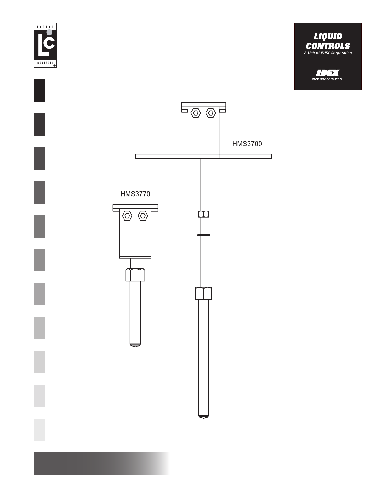
Electromagnetic Flowmeters
Models HMS3700 & HMS3770 Insertion Sensors
Installation
www.lcmeter.com
Page 2

Table of Contents
Description Page Number
Introduction .................................................................................. 2-3
General ........................................................................... 3
Applications ..................................................................... 3
Basic Components .......................................................... 3
Safety Legend ................................................................. 3
Unpacking ....................................................................... 3
Transportation and Handling ........................................... 3
Start up and Maintenance ............................................... 3
Installation .................................................................................... 4-7
Operating Temperature Range ....................................... 4
Dimensions ..................................................................... 4
Sensor Installation Guidelines ........................................ 5
Grounding Instructions .................................................... 5
Model 3770 (installation in non-pressurized systems. .... 6
Model 3700 (installation in pressurized systems) ........... 7
Publication Updates and Translations
The most current English versions of all Liquid Controls publications are available on our website, www.lcmeter.com.
It is the responsibility of the Local Distributor to provide the most current version of LC Manuals, Instructions, and
Specification Sheets in the required language of the country, or the language of the end user to which the products are
shipping . If there are questions about the language of any LC Manuals, Instructions, or Specification Sheets, please
contact your Local Distributor.
!!
WARNING WARNING
!
WARNING
!!
WARNING WARNING
• Before using this product, read and understand the instructions.
• Save these instructions for future reference.
• All work must be performed by qualified personnel trained in the proper application, installation, and maintenance of equipment and/or systems in accordance with all applicable codes and ordinances.
• Failure to follow the instructions set forth in this publication could result in property damage, personal injury,
or death from fire and/or explosion, or other hazards that may be associated with this type of equipment.
Introduction
• This manual is an integral part of the product. Carefully read and understand all the instructions contained in this
publication since it contains important information regarding safety, operation, and maintenance of the instrument.
• The product and technical information contained in this manual may be changed without notice.
• This flow meter must be used only in the applications for which it has been designed. The improper use, tampering
with the instrument, or substitutions of any components immediately voids the product warranty.
• The manufacturer is considered responsible only if the instrument is used in its original configuration.
• Reproduction of this manual or of software supplied with this instrument is expressly forbidden.
2
Page 3
Introduction
General
This manual contains information concerning the application, installation, and operation of the HMS3700 and
HMS3770 insertion flow meters. Keep a copy of this
manual with the flow meter for future reference.
Applications
LCMag electromagnetic flow meters are designed for liquid flow measurement in most industries including water
& waste water, food & beverage, pharmaceutical, chemical, and more. These meters are not suitable for measurement of petroleum products, and other liquid media
with low electrical conductivity. Minimum electrical conductivity of measured liquids is 5µS.
Basic Components
An LCMag electromagnetic flow meter system consists
of two basic components: the flow meter, and the converter. The flow meter is the tube which inserts through
the wall of the pipe and into the liquid flow for measurement. The converter is the electronic control that provides power to the flowmeter and provides signal processing, flow calculation, and display outputs for the user.
The wetted parts of the flow meter (liner and electrodes)
must be selected for compatibility with the liquid being
measured.
Unpacking
Always inspect the instrument for damage from shipping
upon receipt. File a damage claim with the carrier if damage is discovered.
Transportation and Handling
Do not lift the instrument from the carton by the converter head. Use lifting eyes where provided for larger
meters, or lift by the sensor body.
When transporting, never use forks of a forklift, chains,
wire slings, or any other object in the flow tube of the
meter. Serious damage to the instrument will result.
Start up and Maintenance
• Before starting up the instrument, always make sure
that there is a suitable connection to ground as described on Page 5 of this manual.
• Periodically verify the following: the integrity of the
power supply cables, the proper tightening of the
sealing elements (cable glands, covers, etc.), the mechanical attachment of the instrument to the pipe or
to the wall stand.
The converter must be selected for compatibility with the
environment in which it will operate.
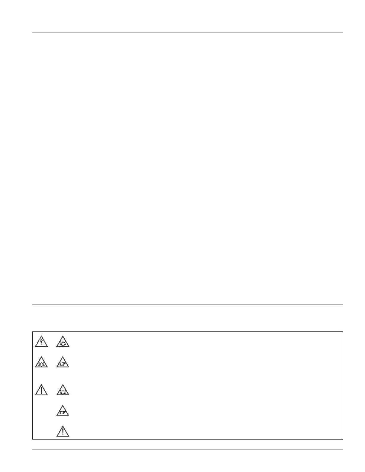
Safety Legend
Before using the instrument, always establish a reliable electrical connection to ground.
Avoid any attempt to repair the instrument. If the instrument is not functioning properly, please call
the nearest authorized representative.
Pay maximum attention during operation.
Caution.
Danger.
3
Page 4

Installation
Flow Direction
Before installing the sensor, confirm the direction of the
liquid flow in the piping. The sign of the flow rate is posi-
tive when the flow direction is from - to + as printed on
the nameplate on the sensor body.
If flow direction is reversed after the installation, it is sufficient to reverse the sign of the KA coefficient in the
converter (refer to converter installation manual).
Operating Temperature Range
PTFE Wetted Parts
Liquid Temp. Ambient Temp.
Min. Max. Min. Max.
°F -4 302 14 140
°C -20 150 -10 60
Dimensions
HMS3700 HMS3770
Size Nominal Pipe Diameter L
1 3" to 20" 19"
2 3" to 40" 24.5"
3 3" to 80" 34.5"
Size Nominal Pipe Diameter L
1 3" to 20" 7"
2 3" to 40" 9.5"
3 3" to 80" 18"
4
Page 5

Sensor Installation Guidelines
NO YES
Installation
For vertical installations
with descending flow
direction contact the
manufacturer.
Avoid operation of the
system with the pipe
partially empty.
Avoid installation of this
instrument near bends
in the piping or accessories such as valves.
If the system is under
pressure, opening the
ball valve before tightening the fixing nut
could result in the
sensor being propelled
from the pipe line.
Never open the ball
valve unless the fixing
nut is properly tightened.
For vertical installations,
use ascending flow
conditions only.
During normal operation
of the instrument, the
pipe must be completely
full of liquid, or completely empty.
Install the sensor away
from bends in the pipe
and accessories such
as valves.
Lock the center bushing
before opening the ball
valve.
Grounding Instructions
For correct operation of the meter, it is essential that the
sensor and the liquid be at the same electrical potential.
Always connect the sensor and the converter to ground.
For grounding with a cathode protection pipe, contact
the manufacturer.
5
Page 6

Installation
Model 3770 (installation in a non-pressurized system)
Step 1
Step 2
Cut the jacket (1"
diameter) to the proper
length “Z”.
Z = L - S - 1/
NOTE: Refer to Step 6
for L dimension.
D - 1.26"
8
Step 4
Tighten the lock nut with
a wrench.
Step 5
Line up the connector
box longitudinally with
pipe line axis.
Tighten the lock nut with
wrench, maintaining the
alignment. Ensure that
the lock nut is tight
enough to create a
proper seal with the
gasket.
Step 3
Recommended dimension of 1" thread.
Weld the jacket to the
pipe line.
Place the gasket on the
sensor.
Place the sensor in the
jacket.
Step 6
Sensor installed
Size Nominal Diameter Range L
Size 1 3" up to 20" 7"
Size 2 3" up to 40" 9.5"
Size 3 3" up to 80" 18"
6
Page 7

Model 3700 (installation in pressurized systems)
Installation
Step 1
Step 2
Step 3
Weld a 1" pipe to the
pipeline.
NOTE: Verify “X”
dimension (Step 2).
X
= 5.5"
MAX
Step 5
Open the valve.
Screw the sensor up to
the “Z” dimension.
Verify the alignment.
Tighten the block nut
maintaining alignment.
Step 4
Screw the 1" jacket to
the valve.
NOTE: The O-Ring in
the jacket must be
placed underside (near
valve).
Insert the sensor with
valve closed.
Tighten the lock nut with
wrench.
Step 6
Size Nominal Diameter Range L
Size 1 3" up to 20" 19"
Size 2 3" up to 40" 24.5"
Size 3 3" up to 80" 34.5"
Length Z = L - S - 1/
D
8
7
Page 8

A Unit of IDEX Corporation
105 Albrecht Drive
Lake Bluff, IL 60044-2242
1.800.458.5262 • 847.295.1050
Fax: 847.295.1057
www.lcmeter.com
© 2005 Liquid Controls
Pub. No. 500339
(3/31/05)
 Loading...