


LINN LP12 TURNTABLE
SET UP MANUAL
Revised Jan 1998
IN THE BEGINNING ...
This is where it all began back in 1973 - the Sondek LP12, which revolutionised people’s perception of what produces ‘good’ hi-fi. At Linn we have demonstrated that turntables are the most important component in a record playing hi-fi system. Twenty five years after its introduction, the LP12 is still the reference turntable.
Since 1973, Linn has invested a great deal of time and effort upgrading the LP12; improvements which have had far reaching effects on the whole system. Today, the LP12 sounds significantly better than at any time in its history, and has an ever expanding customer base. Looking after ‘yesterday’s' customer has always been a priority at Linn, ensuring that almost all the upgrades are retrofittable, thus making it possible to upgrade any
LP12 to current specification and performance.
This section is designed to assist you to carry out any requested upgrades to the LP12, to help you identify and correct minor irregularities, to familiarise you with recommended tools and provide useful information on LP12 specifications. We hope this section will help you provide better service to all your existing and future LP12 customers.
INDEX |
Copyright © 1991-1998 by Linn Products Limited. All Rights Reserved. |
Page 2 |
|
Revised Jan 1998 |
INDEX |
|
Contents ................................................. |
Page |
LP12 Introduction .............................................. |
2 |
LP12 Set-up ..................................................... |
. 4 |
Required Tools ........................................ |
. 5 |
Set-up Jig ................................................ |
. 6 |
Preparation ............................................... |
7 |
Assembly .................................................. |
10 |
Suspension Adjustments .......................... |
14 |
Arm cable fitting ........................................ |
17 |
Motor adjustment ...................................... |
21 |
Final Installation ....................................... |
23 |
Tips ........................................................... |
24 |
Common Turntable Set-up Faults ..................... |
25 |
LP12 Fault Finding ............................................ |
26 |
Lingo Fault Finding ........................................... |
32 |
LP12 Guidelines for Upgrade and Repair |
|
Lingo ......................................................... |
33 |
Suspension Grommets ............................. |
36 |
Motor Thrust Bearing ................................ |
37 |
Bearing Housing “CIRKUS” ...................... |
38 |
Armboard ................................................. |
. 41 |
Suspension Springs .................................. |
41 |
Sub-chassis (glued) .................................. |
42 |
Plinth ......................................................... |
43 |
Valhalla Power Supply .............................. |
44 |
Nirvana Kit ................................................ |
45 |
Valhalla Repair Kit .................................... |
46 |
Valhalla Update Kit ................................... |
47 |
Motor Adjustments .................................... |
48 |
Linn Speedchecker ................................... |
50 |
Kinky Arm Alignment Tool ........................ |
51 |
T-Bar Bolt Straightener ............................. |
52 |
45-rpm Adaptor ......................................... |
53 |
LP12 History and Upgrade Path ....................... |
54 |
LP12 Specifications........................................... |
57 |
Separate Documents: |
|
LP12 Circuitry Fitting Instructions for Basik/Valhalla/Lingo including |
|
Wiring Diagram for Early LP12 ......................... |
LP12_tech_circuitry.pdf |
LP12 Trampolin Fitting Instructions .................. |
LP12_tech_baseboard.pdf |
LP12 Motor Flush Instructions .......................... |
LP12_tech-motorflush.pdf |
INDEX |
Copyright © 1991-1998 by Linn Products Limited. All Rights Reserved. |
Page 3 |

LP12 SET-UP
INTRODUCTION
Revised Jan 1998
Estimated Time for Completion of task ~ 60 minutes
Important - read this before you begin
It is extremely important that you read this entire section before attempting to set up a Linn Sondek LP12 Turntable. Failure to do so may well result in substandard performance, and could result in permanent damage to the turntable.
We realise that the policy of most hi-fi dealers is, “If all else fails, read the instructions”. The set up procedure used on the Linn Sondek, while not terribly difficult, is significantly different from that used on other turntables. It is virtually impossible to set the table up correctly without following the steps in this section.
These instructions refer specifically to the set up of the
Linn Sondek LP12 fitted with a Linn Tonearm and cartridge.
Tightening Procedure
Since we are dealing with a transducer that has to recover information considerably smaller than a millionth of an inch from a phonograph record, it is important that all fasteners (screws, nuts, and bolts) in the turntable be very tight. Whenever the instructions call for you
to tighten a fastener, we do mean tight - probably tighter than you would have imagined.
However, there is no advantage to tightening past the point where materials will deform, or where you damage the materials or destroy their structure. A good rule of thumb is simply to bring the nut or screw up to where it seems tight and then turn it about 1/8 turn more (in the case of armboard screws, which are put into wood, 1/16 turn will do).
INDEX |
Copyright © 1991-1998 by Linn Products Limited. All Rights Reserved. |
Page 4 |
Revised Jan 1998
Tools Needed For Set-Up
5.5mm or 7/32 Hollow Shaft Nut Driver 8mm or 5/16 Hollow Shaft Nut Driver No. 1 Pozidrive Screwdriver
No. 2 Pozidrive Screwdriver
All cross slot screws on the LP12 are Pozidrive. While a Phillips screwdriver will work, the correct Pozidrive screwdriver is preferred.
Medium Size (about 5 mm wide) Flat Blade Screwdriver
Medium Size Needle Nose Pliers
12mm or Adjustable Wrench 5mm or 3/16 Wrench 1.33mm Allen Key
2mm Allen Key 3mm Allen Key 4mm Allen Key
Required allen keys, except for the 3mm, are supplied with Linn tonearms.
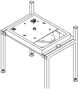
Turntable Set-Up Jig or Substitute
It is desirable to raise the turntable to about eye level so that you can reach and see the underside of the turntable. The set-up jig on a standard-height work bench is best.
The |
surface that |
the set-up jig or turntable rests upon |
must be absolutely |
steady and level for proper suspen- |
|
sion |
adjustment. |
If the surface is unsteady or subject |
to rocking motion, the energy put into the suspension during the adjustment process can induce movement in the support surface as well as the suspension. Proper adjustment of the turntable suspension will be difficult, if not impossible under these conditions.
INDEX |
Copyright © 1991-1998 by Linn Products Limited. All Rights Reserved. |
Page 5 |
Revised Jan 1998
LP12 SET-UP JIG
We recommend that you always use a set-up jig when setting up an LP12. This will facilitate ease of adjustment, prevent damage to your turntable and ensure proper suspension adjustment.
1.Before using the jig make sure that the mounting plates have been covered with a protective strip. Fit protection to underside of clamp and place the jig on a stable surface.
2.Fit plinth carefully to set-up jig and lock in place.
3.Adjust jig feet until plinth is level. Check with a spirit level, both front to back and side to side.
è
level ç
ç |
|
level |
è |
|
INDEX |
Copyright © 1991-1998 by Linn Products Limited. All Rights Reserved. |
Page 6 |

Revised Jan 1998
PREPARATION
The next steps cover unpacking the turntable and checking to see that none of the fasteners (screws, nuts or bolts) have become loose due to vibration in transit.
Caution
Make sure that the turntable is unplugged from the A/C outlet before removing the bottom cover. High Voltages (400 Volts!!!) are present on the Valhalla circuit board. Failure to observe this precaution can result in serious electrical shock.
Please note that, on turntables equipped with the Valhalla circuit board, the board is live at all times. The Valhalla switch does not turn the
A/C power on and off; it simply sends a control pulse to the board which results in the motor being turned on or off.
1. Unpack the Turntable
Packed below the dustcover you will find: An armboard
Two dustcover hinges
Two baseboard screws Three armboard screws
One inner platter/spindle assembly Two phials of main bearing oil
Underneath the turntable you will find:
The outer platter, felt mat, and belt
2. Place Turntable in Set-up Jig
After placing the turntable in the set-up jig, lock the turntable into place. Use a spirit level to ensure that the turntable plinth (base) is level. This is done by adjusting the feet of the set-up jig.
Please note that if you are using a Linn set-up jig, you may lay the jig on its back at various times during set-up to provide easier access to the underside of the turntable (steps 3 to 6 for example).
However, when this is done you should first remove the inner platter and cap the main bearing well with the red plastic cover provided to avoid spillage from the bearing housing if it has been charged with oil.
INDEX |
Copyright © 1991-1998 by Linn Products Limited. All Rights Reserved. |
Page 7 |

Revised Jan 1998
3. Remove Baseboard
Before proceeding with this step, stop and check to make sure the turntable is unplugged! To remove the baseboard, unscrew and remove the four feet on the bottom of the turntable.
If you are working on a previously set-up table, you will also have to remove the two baseboard screws that are located in the centre of both the front and rear edges of the baseboard.
NOTE: If the turntable is to be repacked in its original carton, the two baseboard screws must be removed. If left in, they will scratch the rim of the platter which is packed directly under the turntable.
4. Remove ground and P-Clip Nuts
Use the 8mm nut driver to remove the nut holding the turntable earth jumper wire to the front chassis bolt, and the nuts holding the nylon P-clip, washer, and green
A/C ground wire (if fitted) to the rear chassis bolt. (See Turntable Exploded View).
5. Tighten Wiring Strap Nuts
Check to see that the nuts holding the wiring strap, on which the circuit board is mounted, are tight. These nuts are located directly
under the ones just removed. The chassis bolts pass through the wood mounting blocks of the plinth. These wooden blocks may expand and contract due to temperature and humidity extremes during transit and this can result in the nuts working loose.
Observe the top surface of the stainless steel top plate as you tighten these nuts. Do not overtighten these nuts such that the stainless steel top plate becomes depressed or deformed beneath the heads of the chassis bolts.
6. Tighten Sub-chassis Ground Screw
Tighten the allen head screw which attaches the chassis earth jumper wire to the right rear edge of the sub-chassis.
With older turntables that do not have this screw, proceed to the next step or if welded type,drill the side of subchassis and relocate earth wire.
INDEX |
Copyright © 1991-1998 by Linn Products Limited. All Rights Reserved. |
Page 8 |
Revised Jan 1998
7. Tighten Top Plate Screws
By looking down at the stainless steel top plate from above, locate the two small pozidrive screws that help to attach the top plate to the plinth. They can be found next to the chassis bolts located at the centre front and centre rear of the top plate. Ensure that these two screws are tight.
8. Check the Position of the Motor
Check the position of the motor mounting bolts in the elongated slots in the top plate. These are the two bolts on the extreme right and left of the motor.
On current turntables, (50 Hz pulley, 21mm diameter) the motor mounting bolts should be in the middle of the
adjustment range. |
While |
this |
can be accomplished |
by carefully aligning each |
of the two motor mounting |
||
screws in the middle |
of the slot |
provided, it is easier |
|
and far more accurate to simply have one motor mounting bolt at the extreme outside of its slot, and the other motor mounting bolt at the extreme inside of its slot.
In countries with 60 Hz mains supplies, older turntables may have a smaller (17 mm) diamter pulley. On these LP12s the motor should be in the outermost position. This is accomplished by having both motor mount bolts at the extreme outside of their slots.
Please note:
All new turntables are factory fitted with the larger,
50Hz pulley, and thus should have one motor mounting bolt at the extreme outside of its slot and the other motor mounting bolt at the extreme inside of its slot.
Both Lingo and Valhalla power Suplies use the 50Hz motor/pulley.
Motors with 60 Hz pulleys as supplied in the appropriate BASIK power supply kit and are not compatible with the Lingo or Valhalla power supply.
Original Valhallas supplied to countries with 60 Hz mains were supplied 60 Hz Valhalla boards.
INDEX |
Copyright © 1991-1998 by Linn Products Limited. All Rights Reserved. |
Page 9 |
Revised Jan 1998
9. Check Motor Mounting Nuts
After you have checked the position of the motor mounting bolts, check that the nuts on the motor mounting bolts are tight, using the 5.5 mm nut driver.
Do not over-tighten these nuts or you will simply crush the motor mounting domes!
10. Check Bearing Housing Bolts
Check that the bolts which mount the bearing housing and oil well to the sub-chassis are tight. These are accessible from the top, through the hole in the centre of the stainless steel top plate, by shifting the sub-chassis from one side to another.
Current "Cirkus" LP12 turntables use 4 mm socket head
(Allen key) bolts. Older units may use 2 mm, 2.35 mm 2.5mm or 3mm socket head bolts, Phillips screws, or slotted screws.
POWER SUPPLIES
Since 1991 (serial number 87600) the LP12 has been supplied as a mechanical assembly only, without power supply factory fitted.
Three different power supply options are available: Lingo, Valhalla and Basik. Valhalla and Basik. If you are setting up a new turntable see separate instructions for fitting the power supply.
ASSEMBLY
Some instructions in this section, concerning certain tools and fasteners, are specific to Linn tonearms.
Procedures may vary slightly if other tonearms are used.
11. Mount the Tonearm Base on the Armboard
In the case of the Linn arms, the arm base is fastened from the bottom of the arm board with three 4mm socket head bolts with lock washers.Read section on Kinky arm alignment tool before proceeding.
To Locate Properly
With arms using other mountings, ensure that the mounting screws, bolts, or nuts are properly tightened observing the tightening procedure. With arms using a single large mounting nut, reaching the proper tightness does require the use of a spanner, not just your fingers!
INDEX |
Copyright © 1991-1998 by Linn Products Limited. All Rights Reserved. |
Page 10 |
Revised Jan 1998
12. Mount the Arm Rest - Ittok LVII/LVIII
When fitting the Linn Ittok LV11 arm, mount the armrest on the armboard in the hole provided. This will need to be drilled out.
Position the LVII armrest such that its knurled height locking screw will be to the outside when the armboard is mounted on the turntable.
Tighten the mounting nut on the underside of the armrest very tightly with a 12 mm or adjustable wrench. Tighten the knurled height locking screw only finger tight for now.
After you make the final arm height adjustments you will likely need to re-readjust the height of the armrest, before finally locking it in position.
13. Mount Tonearm collar
Place the tonearm in the mounting collar on the armboard.
Tighten the screws fingertight only at this stage.
14. Mount the Arm Board
Use only the screw supplied for mounting the armboard. Do not substitute any other screws for the supplied screws!
Mount the armboard on the turntable sub-chassis. leave the screws slightly loose at this point.
15. Mount the Cartridge
Mount the cartridge on the tonearm with stainless steel cartridge nuts and bolts, as supplied with all Linn tonearms and cartridges. Do not completely tighten down the mounting bolts at this time. The cartridge must be mounted loosely enough to allow you to shift its position with your fingers for alignment before finally locking it in position. See Seperate proccedure for complete details.
16. Charge Turntable Bearing with Oil
Discharge the entire charge of oil provided into the bearing well - i.e. two small 1 ml phials of Linn oil. Wrap a tissue around the bearing housing to absorb any overflow.
INDEX |
Copyright © 1991-1998 by Linn Products Limited. All Rights Reserved. |
Page 11 |
Revised Jan 1998
17. Fit Inner
Carefully insert the inner platter/spindle assembly into the bearing well and gently lower into position; ensure that you support it while lowering. Do not drop the inner into the bearing well, as irreparable damage may result!
When the spindle reaches the bottom of the well, a small amount of oil should flow from the top of the well. No overflow indicates an insufficient amount of oil. In this case remove the inner platter from the well and add more oil (say 5 drops at a time) until a small overflow results when the inner platter is again carefully placed into the well. Once this oil reservoir is full raise the inner platter to remove and discard tissue.
18. Install the Belt
Upon inspecting the belt you may find that one surface is slightly smoother than the other The smoother side should be considered the INSIDE of the belt. (If the turntable has been used, the inside of the belt can be identified by a thin, polished silver pulley track running along near the centre of the belt - clean before refitting) Fit the belt to the motor pulley and outside surface of the inner platter.
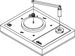
19.Mount the tonearm |
|
|
|
Align using |
"KINKY" |
alignment tool |
to |
detemine correct location for the arm- |
|
||
board, see separate procedure for |
Kinky |
||
"Kinky" Alignment tool for for |
Alignment |
||
details. Take |
care not |
to |
Gauge |
strip the holes in the |
|
|
|
armboard. If |
you do, |
|
|
replace the armboard; |
|
|
|
refer to tightening |
|
|
|
procedure. |
|
|
|
Fit the tonearm into the collar and lock
the tonearm temporarily in place at correct height by lightly tightening the height locking
screw in the tonearm base (See procedure on Mounting the Cartridge for details).
20. Tonearm Counterweight
Gently fit the counterweight on the tonearm, being careful not to subject the arm bearings to undue force.
INDEX |
Copyright © 1991-1998 by Linn Products Limited. All Rights Reserved. |
Page 12 |
Revised Jan 1998
On dynamically balanced |
tonearms such as the Linn |
|
Ekos/Ittok, |
balance the |
weight of the cartridge by |
adjusting |
the counterweight position; then apply the |
|
required tracking force with the tracking weight dial. |
||
On statically balanced tonearms such as the Linn Akito/
Basik, balance the |
weight of the cartridge with the |
counterweight position; |
then adjust the tracking dial |
(without moving the counterweight) to put the zero weight
position in line with the mark on the arm, under the |
“0” |
line position. Rotate the counterweight such that |
it |
moves towards the bearing housing (towards you) until the line indicates the desired tracking weight on the counterweight dial.
21. Install Outer Platter and Mat
Carefully fit the outer platter onto the inner platter. Place the felt mat on top of the platter surface.
22. Align the Cartridge
Place a flat record on the platter.
Align the cartridge position in the tonearm headshell using the Linn alignment protractor. See Cartridge procedure for details.
After aligning the cartridge, remove the tonearm from the turntable and tighten down the cartridge with a 2 mm allen key while holding the nuts with a 5 mm wrench.
Linn cartridges must be mounted very tightly in the headshell. If the cartridge body is not strong enough to allow it to be mounted tightly,
it cannot perform at its best. All Linn cartridges, except the K5, are metal bodies and can be tightened properly.
To avoid damaging critical arm bearings never, under any circumstances, tighten or loosen cartridge mounting hardware with the tonearm mounted on the turntable!
Force applied at the headshell can, by way of the lever action of the arm tube, be amplified and transmitted to the delicate precision bearings of the arm. This damages the bearings. The main pillar of the arm must always be allowed to move freely (i.e. not be attached to the mass of the turntable) when a cartridge is tightened in the headshell.
INDEX |
Copyright © 1991-1998 by Linn Products Limited. All Rights Reserved. |
Page 13 |
Revised Jan 1998
23. Adjust Tonearm Height (vertical tracking angle)
Replace the tonearm and adjust the height so that the arm tube is parallel to the surface of the record on which the stylus rests. Lock the tonearm in position with the
4 mm allen key supplied.
The tonearm should be very |
tightly locked. Again, |
||||
ensure the proper |
restraint. Do |
not |
use any additional |
||
bar |
on the |
allen |
key to gain added |
torque. Doing so |
|
will |
make it |
possible to tighten the arm height lock bolt |
|||
to |
the point where the arm pillar (and hence the arm |
||||
bearings) is |
deformed. |
|
|
||
If mounting a Linn Ittok LVIII arm, at this time you should readjust the height of the arm rest and tighten the knurled height locking screw as tightly as possible.
SUSPENSION ADJUSTMENTS
Level Set-up Jig
Use a spirit level to check once again that the turntable plinth is level. Adjust the set-up jig feet if necessary.
25. Level Suspension
Level the suspension by turning the nuts under the three spring/grommet assemblies up or down. The rear of the armboard should be levelled by adjusting the nut under the rear spring assembly. The front of the armboard should be levelled by adjusting the nut under the front spring assembly and the suspended system as a whole should be levelled left to right by adjusting the nut under the left spring assembly.
When the suspension is levelled correctly, the top of the armboard should be flush with the top edge of the plinth, and the platter should be level relative to all edges of the plinth. Do not align to the inside edge of the top plate (the one parallel to the armboard) as this is part of the suspension and it is not unusual for this to have a sight dip.
26. Adjust Springs
It is necessary that the suspension is allowed to move freely in all directions, and that it be adjusted so that it bounces easily, straight up and down. This can be tested by gently tapping the platter in the area where the inner
INDEX |
Copyright © 1991-1998 by Linn Products Limited. All Rights Reserved. |
Page 14 |

Revised Jan 1998
and outer platters meet, on a straight line between the centre spindle and the tonearm bearing housing. The whole suspended system should bounce straight up and down with no sideways or erratic motions.
If it is necessary to adjust the suspension, first check that the grommets are properly seated. Then unplug the signal lead from arm. Begin with the spring/grommet assembly on the left side of the turntable. Rotate the entire spring/grommet assembly a little at a time (1/16 to 1/8 turn) until the action of the suspension is as straight as possible. Next, move to the front spring/ grommet assembly and adjust it in a similar manner. Lastly, move to the rear spring/grommet assembly and adjust it in the same manner.
Large
Grommet
 Spring
Small
Grommet
Washer
Large nut.
Each time you rotate a spring/grommet assembly, ensure that the entire assembly rotates during adjustment so that you do not introduce a twist in the spring. As you finish adjusting each spring, push up slightly and then release the washer on which the spring/grommet assembly rests. This will release any twist which may have been introduced into the spring.
Note that as you rotate a spring, the level of the suspension may change. If this is the case, re-adjust the level as necessary before moving to the next spring.
Once you have adjusted all three springs, if the suspension is not satisfactory repeat the adjustments, starting again at the left, moving to the front and then to the rear. You may occasionally have to go around the table two or three times to fully adjust the suspension.
When you are finished, the suspension should be able to move freely in any direction, and move roughly straight up and down when tapped as described earlier.
If you should have problems, make sure that you have not moved the suspended assembly to a position in which any top grommet touches the chassis bolt that passes through it. Also, check that the armboard is not touching the stainless top plate or the plinth.
INDEX |
Copyright © 1991-1998 by Linn Products Limited. All Rights Reserved. |
Page 15 |
Revised Jan 1998
27. Check Suspension
When you are finished with step 26 there is one last test. Remove the outer platter (to enable the suspension to relax) and then replace it onto the inner platter. If the suspension still works properly you are finished with the operation.
If the suspension no longer moves straight up and down this may be an indication that one or more of the springs was not properly seated on the top rubber grommet. The springs should be readjusted as outlined in step 25.
Don’t panic. While the suspension adjustment may seem a bit complicated, it is actually quite simple. With a bit of practice you will find that it is easier to adjust the suspension than it is to read about it.
INDEX |
Copyright © 1991-1998 by Linn Products Limited. All Rights Reserved. |
Page 16 |
Revised Jan 1998
ARM CABLE FITTING
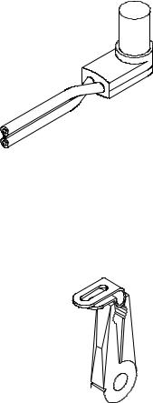
28. Straighten Cable
Before moving the arm cable, straighten any bends or kinks it has from having been packed. If necessary, heating the cable slightly with a
hair dryer is permissible.
After straightening the cable, put a 90 degree twist in it right behind the plug, as shown .
29. Pre-form P-Clip
Pre-form the P-clip by squeezing it tightly together momentarily with a pair of pliers, as shown in the illustration.
INDEX |
Copyright © 1991-1998 by Linn Products Limited. All Rights Reserved. |
Page 17 |
Revised Jan 1998
30.Re-attach A/C Earth Wire (Valhalla / Basik)
Replace the green A/C earth wire, and associated nut, on the rear chassis bolt and tighten securely.
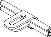
31.Put P-clip on the Arm Cable
Place the P-clip on the arm cable about 170 mm from the plug. (The accuracy of this distance is not critical.) To achieve the tightest clamp-
ing of the arm cable, it should be passed through the P-clip such that the cable’s wide dimension will run vertically, as shown in the illustration.
Slip the washer, P-clip, and associated nut onto the rear chassis bolt with the loop of the P-clip towards the rear of
the turntable. Do not tighten the nut at this time.
32. Replace Chassis Earth Wire
Replace the chassis earth jumper wire, and associated nut, on the front chassis bolt and tighten securely.
33. Attach Arm Earth
Cut eyelet on the armlead's ground wire. Remove insulation approximately 5 mm and solder to eyelet of chassis ground wire where it is affixed to the sub-chassis by the allen head screw.
If you are setting up an older LP12 that does not have this allen screw attaching the chassis earth, it is recommended that you drill a small hole (3mm) on the side of the sub-chassis and relocate the earth wires to this point.
Use stainless steel cartridge mounting nut and bolt.
34. Plug in Arm Cable
Plug the cable into the arm. Allow enough slack so that the cable is not pulling on the suspension, but not enough to allow the cable to dip and rest on the bottom panel or to push on the suspension.
INDEX |
Copyright © 1991-1998 by Linn Products Limited. All Rights Reserved. |
Page 18 |
 Loading...