


LRDN22734WW

CAUTION
BEFORE SERVICING THE UNIT,
READ THE SAFETY PRECAUTIONS IN THIS MANUAL.
REFRIGERATOR
SERVICE MANUAL
Models:
LRDN22734SB
LRDN22734ST
LRDN22734TT
LRDN22734WW

SAFETY PRECAUTIONS ....................................................................................................................................................... 2
SPECIFICATIONS................................................................................................................................................................... 3
PARTS IDENTIFICATION.................................................................................................................................................... 4-7
DISASSEMBLY.................................................................................................................................................................... 8-9
DOOR................................................................................................................................................................................... 8
DOOR SWITCH.................................................................................................................................................................... 8
FAN AND FAN MOTOR........................................................................................................................................................ 9
DEFROST CONTROL ASSEMBLY...................................................................................................................................... 9
LAMP.................................................................................................................................................................................... 9
CONTROL BOX-REFRIGERATOR...................................................................................................................................... 9
MULTI DUCT ........................................................................................................................................................................ 9
ADJUSTMENT.................................................................................................................................................................. 10-11
COMPRESSOR.................................................................................................................................................................. 10
PTC-STARTER.................................................................................................................................................................. 10
OLP (OVERLOAD PROTECTOR)....................................................................................................................................... 11
TO REMOVE THE COVER PTC..........................................................................................................................................11
CIRCUIT DIAGRAM.......................................................................................................................................................... 12-13
TROUBLESHOOTING...................................................................................................................................................... 14-19
COMPRESSOR AND ELECTRIC COMPONENTS ........................................................................................................... 14
PTC AND OLP.................................................................................................................................................................... 15
OTHER ELECTRICAL COMPONENTS............................................................................................................................. 16
SERVICE DIAGNOSIS CHART.......................................................................................................................................... 17
REFRIGERATION CYCLE ............................................................................................................................................ 18-19
OPERATION PRINCIPLE & REPAIR METHOD OF ICEMAKER .................................................................................. 20-23
DESCRIPTION OF FUNCTION & CIRCUIT OF MICOM (BEST, DISPENSER) ............................................................. 24-44
CONTENTS
- 2 -
Please read the following instructions before servicing your
refrigerator.
1. Check the refrigerator for electrical faults.
2. To prevent electric shock, unplug before servicing.
3. Always check line voltage and amperage.
4. Use standard electrical components.
5. Don't touch metal products in the freezer with wet
hands. This may cause frostbite or cause your skin to
freeze and stick to the surfaces inside the freezer.
6. Prevent water from flowing onto electric elements in the
mechanical parts.
7. Close the top door before opening the bottom door.
Otherwise, you might hit your head when you stand up.
8. When tilting the refrigerator, remove any materials on
the refrigerator, especially the glass shelves and stored
foods.
9. When servicing the evaporator, wear cotton gloves.
This is to prevent injuries from the sharp evaporator
fins.
10. Disassembly, repair, and servicing the sealed
refrigeration system should be performed only by
qualified and certified personnel. Refrigerant should
not be vented into the atmosphere; proper recovery
equipment should be used.
SAFETY PRECAUTIONS
DESCRIPTION OF FUNCTION & CICUIT OF MICOM (GOOD, BETTER) ..................................................................... 45-64
REFRIGERATOR EXPLODED VIEW & SERVICE PARTS LIST.......................................................................................65-102
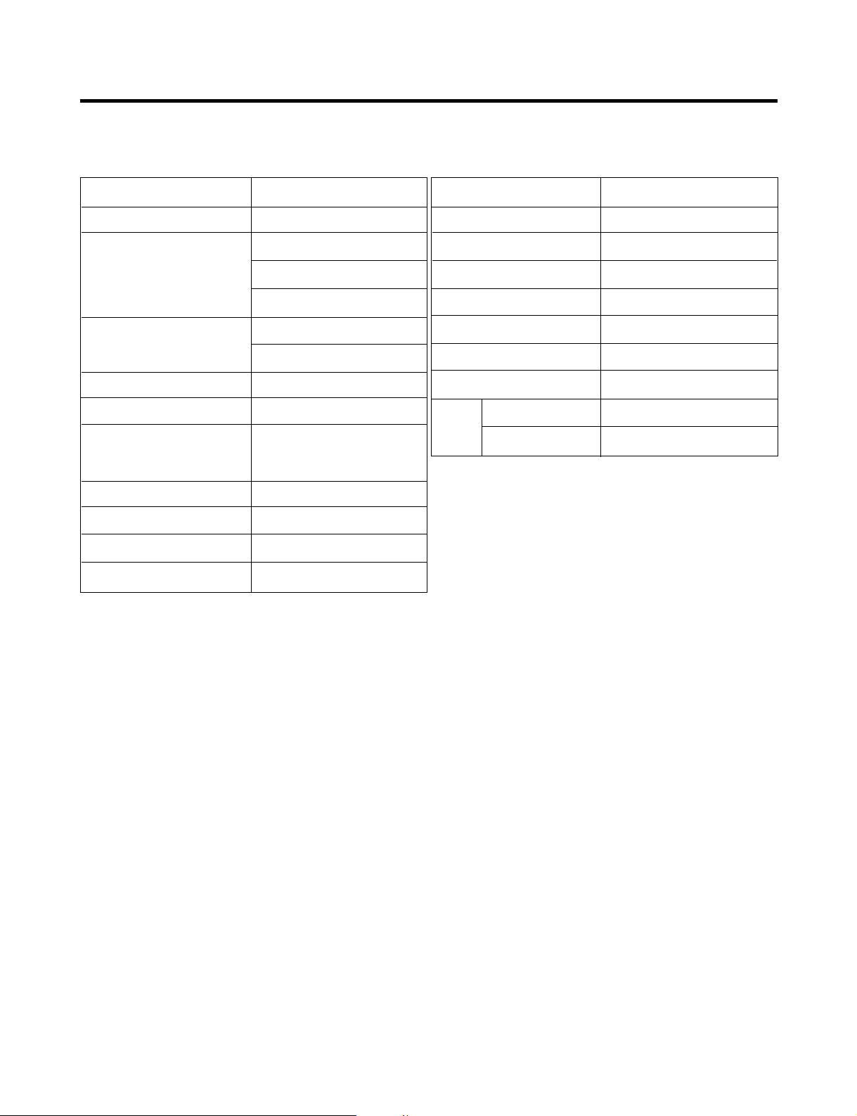
1. SPECIFICATIONS
- 3 -
ITEMS SPECIFICATIONS
DOOR DESIGN Side Rounded
29
7
/
8 X 31
3
/
4 X 67
7
/
8 (WXDXH) 20cu.ft
DIMENSIONS (inches)
32
7
/8 X 31
3
/4 X 69
1
/2 (WX
DXH) 22cu.ft Dispenser
32
7
/8 X 31
3
/4 X 68
1
/2 (WX
DXH) 22cu.ft
NET WEIGHT (pounds)
238.4 (
20cu.ft)
246.9 (
22cu.ft)
COOLING SYSTEM Fan Cooling
TEMPERATURE CONTROL Micom Control
Full Automatic
DEFROSTING SYSTEM
Heater Defrost
DOOR FINISH Embossed Metal, VCM, Stainless
HANDLE TYPE Bar, Al
INNER CASE ABS Resin
INSULATION Polyurethane Foam
ITEMS SPECIFICATIONS
VEGETABLE TRAY Opaque Drawer Type
COMPRESSOR PTC Starting Type
EVAPORATOR Fin Tube Type
CONDENSER Wire Condenser
REFRIGERANT R-134a (115 g)
LUBRICATING OIL Freol @ 10G (310 cc)
DEFROSTING DEVICE SHEATH HEATER
LAMP
REFRIGERATOR 60 W (2EA)
FREEZER 60 W (2EA)
20 cu. ft. / 22 cu. ft.
A
B
C
D
E
F
G
H
I
J
K
L
M
N
O
P
Q
R
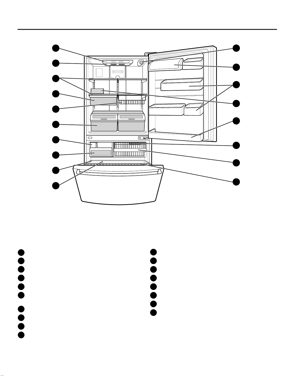
Digital Sensor Control
Refrigerator Light
Shelves
Chef Fresh / Snack Pan*
Can Dispenser*
Optibin Crisper
Keeps fruits and vegetable fresh and crisper
Customcube Icemaker
Ice Bin
Durabase
Divider
Filter (inside)*
Dairy Bin
Design-A-Door
Egg Box
Refrigerator Door Rack
Freezer Light
Wire Basket
Freezer Door Rack (Tilting*)
*on some models
B
C
D
A
F
E
NOTE:This guide covers several different models.The refrigerator you have purchased may have some
or all of the items listed below. The locations of the features shown below may not match your model.
G
H
I
J
K
M
N
L
O
P
Q
R
PARTS AND FEATURES
2. PARTS IDENTIFICATION
- 4 -

A
B
C
D
E
F
G
H
I
J
K
L
M
N
O
P
Q
R
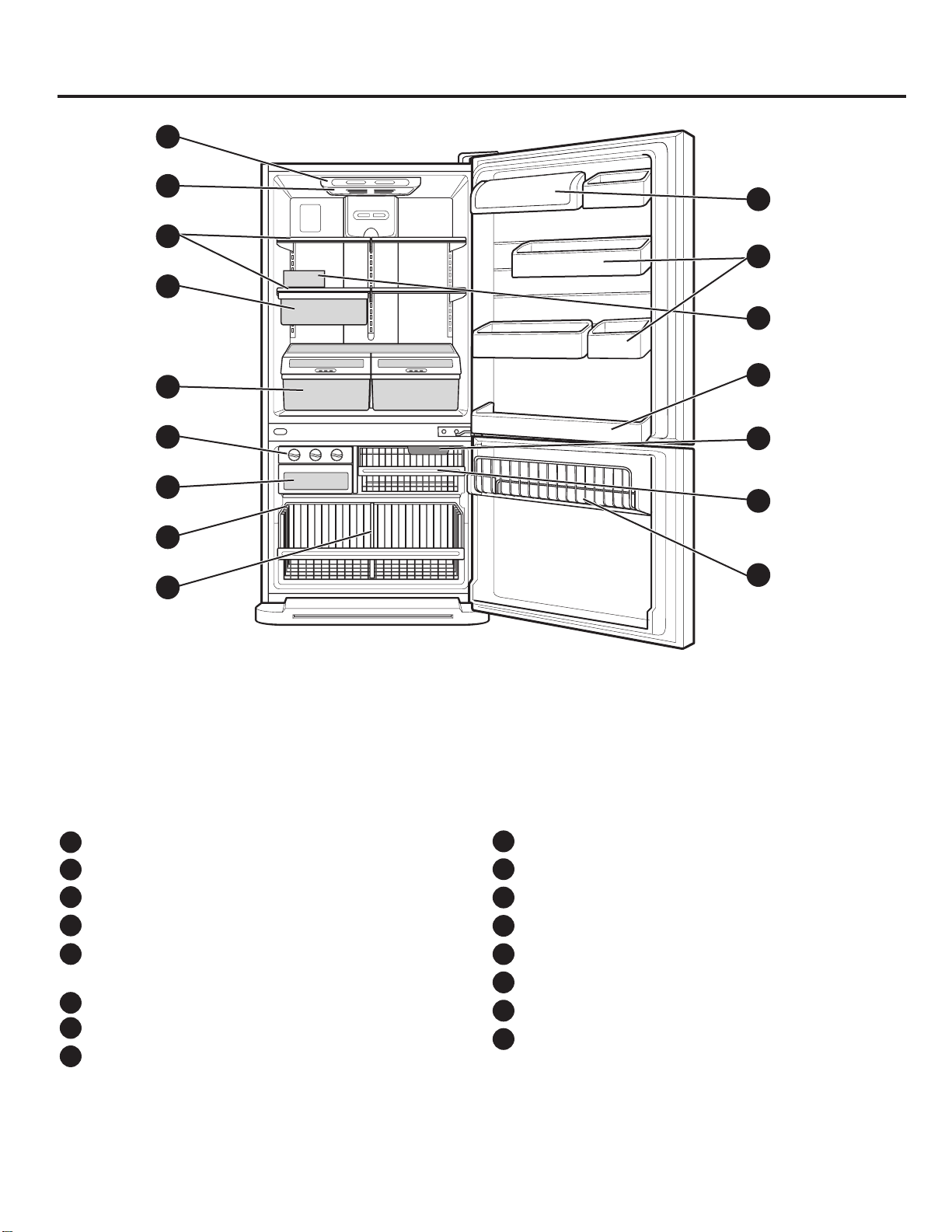
Digital Sensor Control
Refrigerator Light
Shelves
Chef Fresh / Snack Pan*
Can Dispenser*
Optibin Crisper
Keeps fruits and vegetable fresh and crisper
Triple Ice Tray
Ice Bin
Durabase
Divider
Filter (inside)*
Dairy Bin
Design-A-Door
Egg Box
Refrigerator Door Rack
Freezer Light
Wire Basket
Freezer Door Rack (Tilting*)
*on some models
B
C
D
A
F
E
NOTE:This guide covers several different models.The refrigerator you have purchased may have some
or all of the items listed below. The locations of the features shown below may not match your model.
G
H
I
J
K
M
N
L
O
P
Q
R
PARTS AND FEATURES
- 5 -
NOTE:This guide covers several different models.The refrigerator you have purchased may have some
or all of the items listed below. The locations of the features shown below may not match your model.
A
B
C
D
E
F
G
H
I
J
K
L
M
N
P
O
Digital Sensor Control
Refrigerator Light
Shelves
Snack Pan
Optibin Crisper
Keeps fruits and vegetable fresh and crisp
Triple Twist Ice Tray
Ice Bin
Wire Durabase
Divider
Dairy Bin
Design-A-Door
Egg Box
Refrigerator Door Rack
Freezer Light
Wire Basket
Freezer Wire Door Rack
B
C
D
A
F
E
G
H
I
J
L
M
K
N
O
P
PARTS AND FEATURES
- 6 -

NOTE:This guide covers several different models.The refrigerator you have purchased may have some
or all of the items listed below. The locations of the features shown below may not match your model.
PARTS AND FEATURES
Digital Sensor Control
Refrigerator Light
Shelves
Snack Pan
Optibin Crisper
Keeps fruits and vegetable fresh and crisp
Ice Trays
Ice Bin
Wire Durabase
Dairy Bin
Design-A-Door
Wire Freezer Shelf
Refrigerator Door Rack
Freezer Light
Freezer Door Rack
B
C
D
A
F
E
G
H
I
J
L
M
K
N
A
B
C
D
E
F
G
H
I
J
M
N
L
K
- 7 -
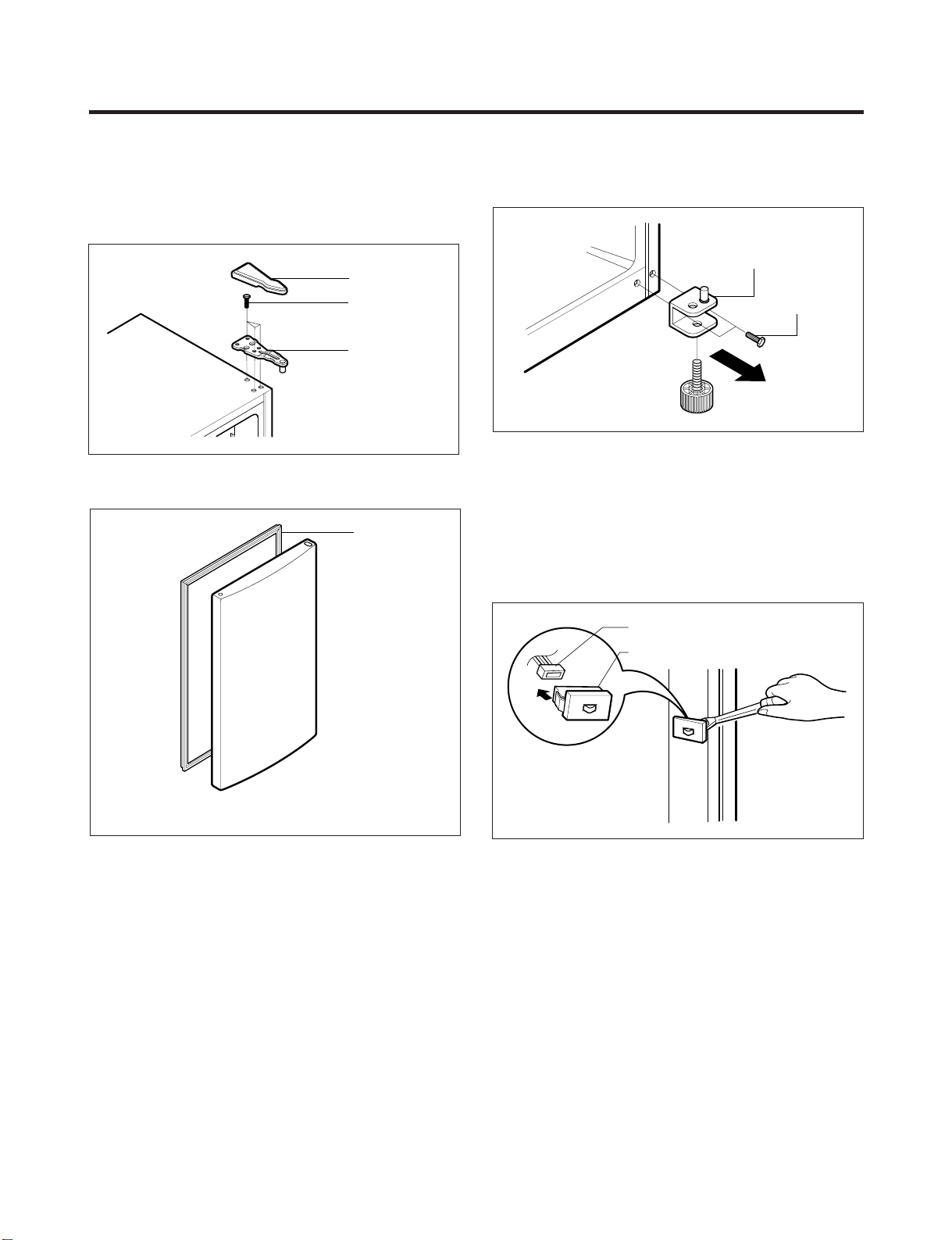
3-1 DOOR
● Refrigerator Door
1. Remove the hinge cover by pulling it upwards.
2. Loosen the hexagonal bolts attaching the upper hinge to
the body and lift the freezer door.
3. Pull out the door gasket to remove from the door foam
assembly.
● Freezer Door
1. Loosen the hexagonal bolts attaching the lower hinge to
the body to remove the refrigerator door only.
2. Pull out the door gasket to remove from the door foam
assembly.
3-2 DOOR SWITCH
1. To remove the door switch, pry it out with a slotted-type
driver, as shown in (Figure 4).
2. Disconnect the lead wire from the switch.
3. DISASSEMBLY
- 8 -
BOLT
HINGE
HINGE COVER
Figure 1
GASKET
Figure 2
LOWER HINGE
BOLT
Figure 3
DOOR SWITCH
LEAD WIRE
Figure 4
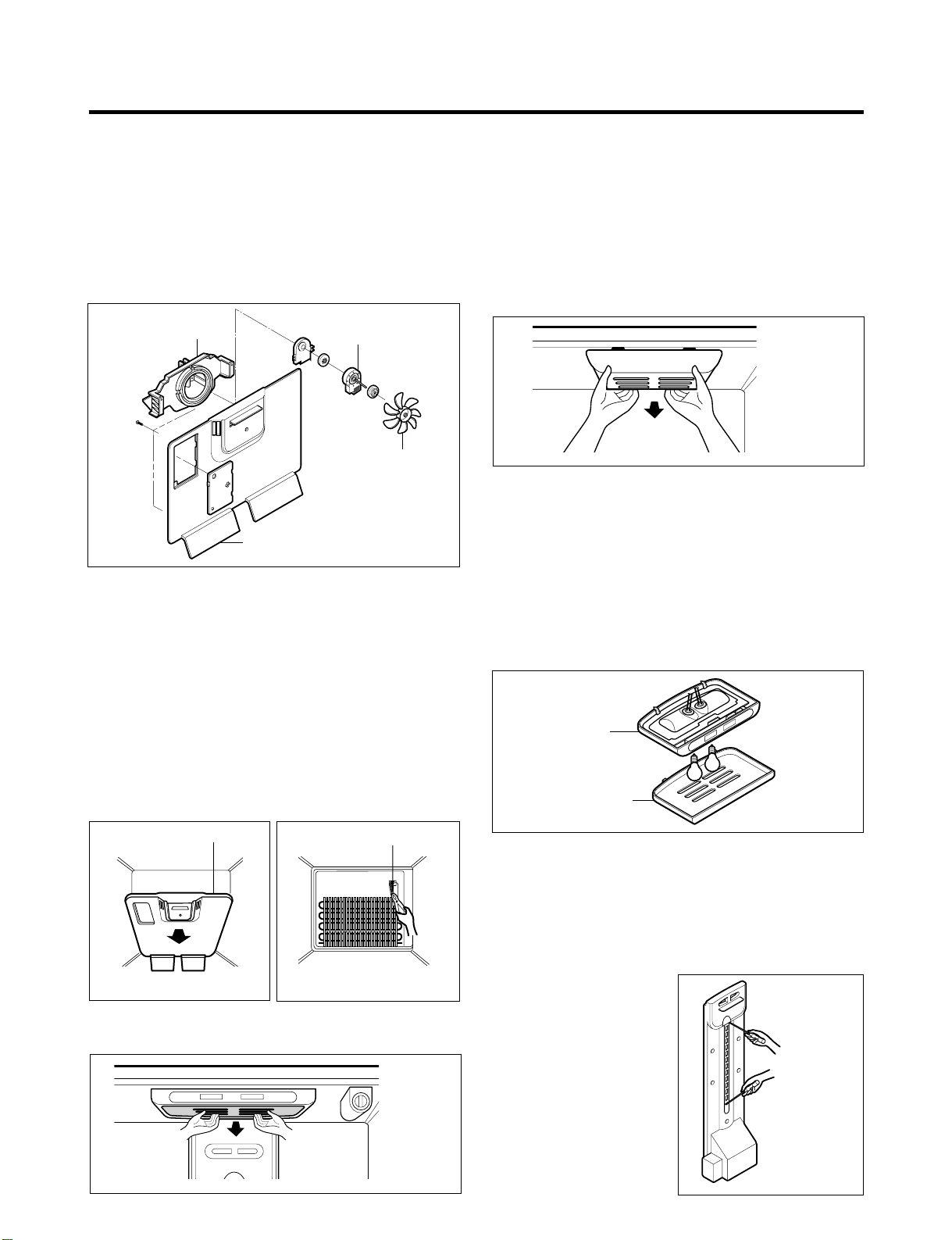
3-3 FAN AND FAN MOTOR
1. Remove the freezer shelf. (If your refrigerator has an
icemaker, remove the icemaker first)
2. Remove the grille by pulling it out and by loosening a
screw.
3. Remove the Fan Motor assembly by loosening 2 screws
and disassemble the shroud.
4. Pull out the fan and separate the Fan Motor and Bracket.
3-4 DEFROST CONTROL ASSEMBLY
Defrost Control assembly consists of Defrost Sensor and
FUSE–M.
The Defrost Sensor works to defrost automatically. It is
attached to the metal side of the Evaporator and senses its
temperature. At 72°C, it turns the Defrost Heater off.
Fuse-M is a safety device for preventing over-heating of
the Heater when defrosting.
1. Pull out the grille assembly. (Figure 6)
2. Separate the connector with the Defrost Control
assembly and replace the Defrost Control assembly
after cutting the Tie Wrap. (Figure 7)
3-5 LAMP
3-5-1 Refrigerator Compartment Lamp
1. Unplug the power cord from the outlet.
2. Remove refrigerator shelves.
3. Release the hooks on both ends of the lamp shield and
pull the shield downward to remove it.
4. Turn the lamp counterclockwise.
5. Assemble in reverse order of disassembly. Replacement
bulb must be the same specification as the original
(Max. 60 W-2EA).
3-5-2 Freezer Compartment Lamp
1. Unplug refrigerator or disconnect power.
2. Reach behind light shield to remove bulb.
3. Replace bulb with a 60-watt appliance bulb.
4. Plug in refrigerator or reconnect power.
3-6 CONTROL BOX-REFRIGERATOR
1. First, remove all shelves in the refrigerator, than remove
the Refrigerator control Box by loosening 2 screws.
2. Remove the Refrigerator Control Box by pulling it
downward.
3. Disconnect the lead wire on the right position and
separate the lamp sockets.
3-7 MULTI DUCT
1. Remove an upper and
lower Cap by using a flat
screwdriver, and loosen 3
screws. (Figure 11)
2. Disconnect the lead wire
on the bottom position.
- 9 -
FAN
BRACKET
MOTOR
GRILLE
FAN MOTOR
Figure 5
GRILLE ASSEMBLY
Figure 6
DEFROST-CONTROL
ASSEMBLY
Figure 7
Figure 8
Figure 9
CONTROL BOX
COVER LAMP
Figure 10
Figure 11
4-1 COMPRESSOR
4-1-1 Role
The compressor intakes low temperature and low pressure
gas from the evaporator of the refrigerator and compresses
this gas to high-temperature and high-pressure gas. It then
delivers the gas to the condenser.
4-1-2 Composition
The compressor includes overload protection. The PTC
starter and OLP (overload protector) are attached to the
outside of the compressor. Since the compressor is
manufactured to tolerances of 1 micron and is hermetically
sealed in a dust and moisture-free environment, use
extreme caution when repairing it.
4-1-3 Note for Usage
(1) Be careful not to allow over-voltage and over-current.
(2) If compressor is dropped or handled carelessly, poor
operation and noise may result.
(3) Use proper electric components appropriate to the
Particular Compressor in your product.
(4) Keep Compressor dry.
If the Compressor gets wet (in the rain or a damp
environment) and rust forms in the pin of the Hermetic
Terminal, poor operation and contact may result.
(5) When replacing the Compressor, be careful that dust,
humidity, and soldering flux don’t contaminate the inside
of the compressor. Dust, humidity, and solder flux
contaminate the cylinder and may cause noise,
improper operation or even cause it to lock up.
4-2 PTC-STARTER
4-2-1 Composition of PTC-Starter
(1) PTC (Positive Temperature Coefficient) is a no-contact
semiconductor starting device which uses ceramic
material consisting of BaTiO
3.
(2) The higher the temperature is, the higher the resistance
value. These features are used as a starting device for
the Motor.
4-2-2 Role of PTC-Starter
(1) The PTC is attached to the Sealed Compressor and is
used for starting the Motor.
(2) The compressor is a single-phase induction motor.
Durign the starting operation, the PTC allows current
flow to both the start winding and main winding.
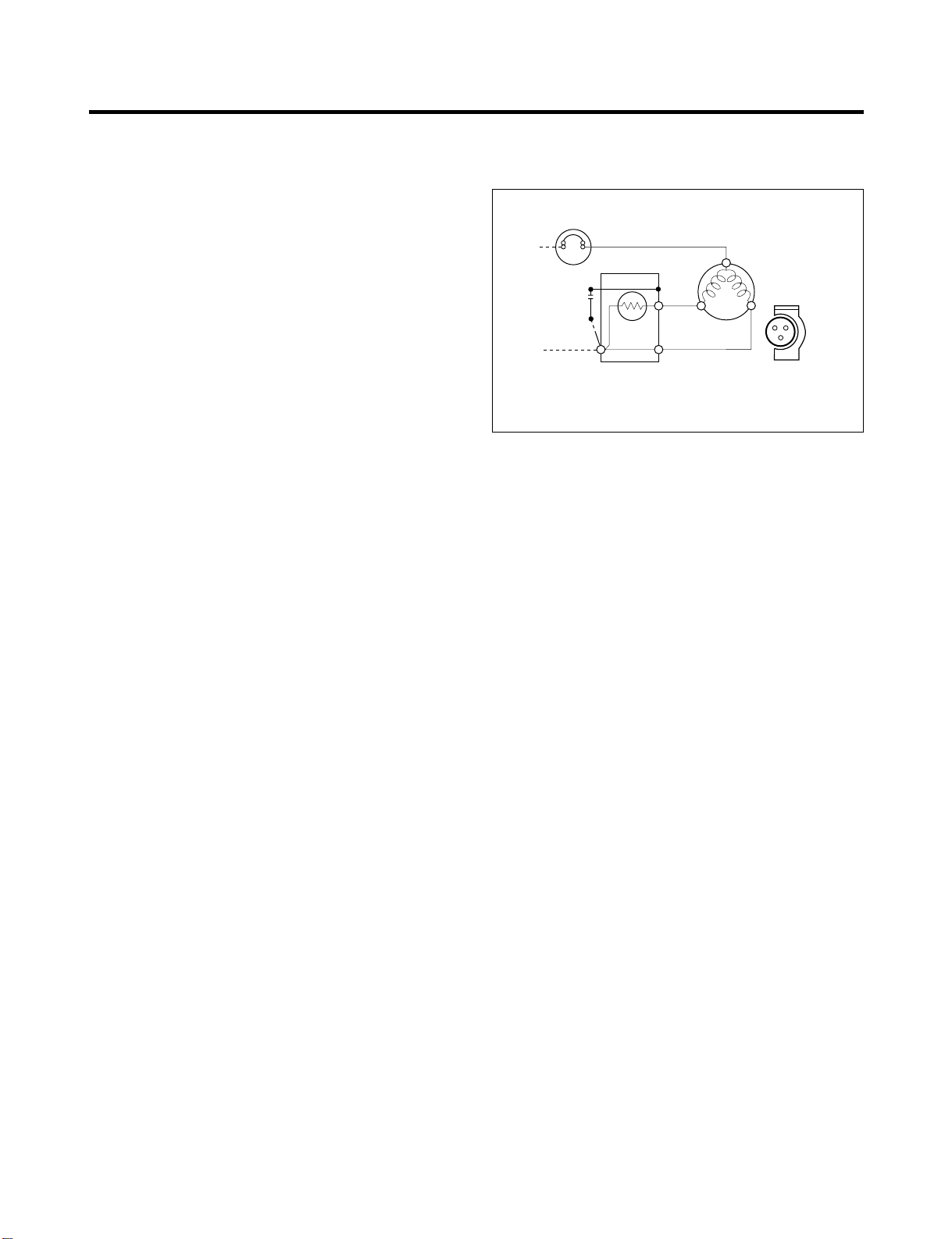
4-2-3 PTC-Applied Circuit Diagram
● Starting Method for the Motor
4-2-4 Motor Restarting and PTC Cooling
(1) It requires approximately 5 minutes for the pressure to
equalize before the compressor can restart.
(2) The PTC device generates heat during operation.
Therefore, it must be allowed to cool before the
compressor can restart.
4-2-5 Relation of PTC-Starter and OLP
(1) If the compressor attempts to restart before the PTC
device is cooled, the PTC device will allow current to
flow only to the main winding.
(2) The OLP will open because of the over current
condition. This same process will continue (3 to 5
times) when the compressor attempts to restart until
the PTC device has cooled. The correct OLP must be
properly attached to prevent damage to the
compressor.
Parts may appear physically identical but could have
different electrical ratings. Replace parts by part
number and model number. Using an incorrect part
could result in damage to the product, fire, injury, or
possibly death.
4-2-6 Note for Using the PTC-Starter
(1) Be careful not to allow over-voltage and over-current.
(2) Do not drop or handle carelessly.
(3) Keep away from any liquid.
If liquid such as oil or water enters the PTC,
PTC materials may fail due to breakdown of their
insulating capabilities.
(4) If the exterior of the PTC is damaged, the resistance
value may be altered. This can cause damage to the
compressor and result in a no-start or hard-to-start
condition.
(5) Always use the PTC designed for the compressor and
make sure it is properly attached to the compressor.
Parts may appear physically identical but could have
different electrical ratings. Replace parts by part
number and model number. Using an incorrect part
could result in damage to the product, fire, injury, or
possibly death.
4. ADJUSTMENT
- 10 -
PTC STARTER
SEALED
TERMINAL
COMPRESSOR
MOTOR
C
M
S
M
3
6
5
2
S
PTC
N
L1
OVERLOAD PROTECTOR
Resistance Starter Capacitor Running
Figure 12
4-3 OLP (OVERLOAD PROTECTOR)
4-3-1 Definition of OLP
(1) OLP (OVERLOAD PROTECTOR) is attached to the
Compressor and protects the Motor by opening the
circuit to the Motor if the temperature rises and
activating the bimetal spring in the OLP.
(2) When high current flows to the Compressor motor, the
Bimetal works by heating the heater inside the OLP,
and the OLP protects the Motor by cutting off the
current flowing to the Compressor Motor.
4-3-2 Role of the OLP
(1) The OLP is attached to the Sealed Compressor used
for the Refrigerator. It prevents the Motor Coil from
being started in the Compressor.
(2) For normal operation of the OLP, do not turn the Adjust
Screw of the OLP in any way.
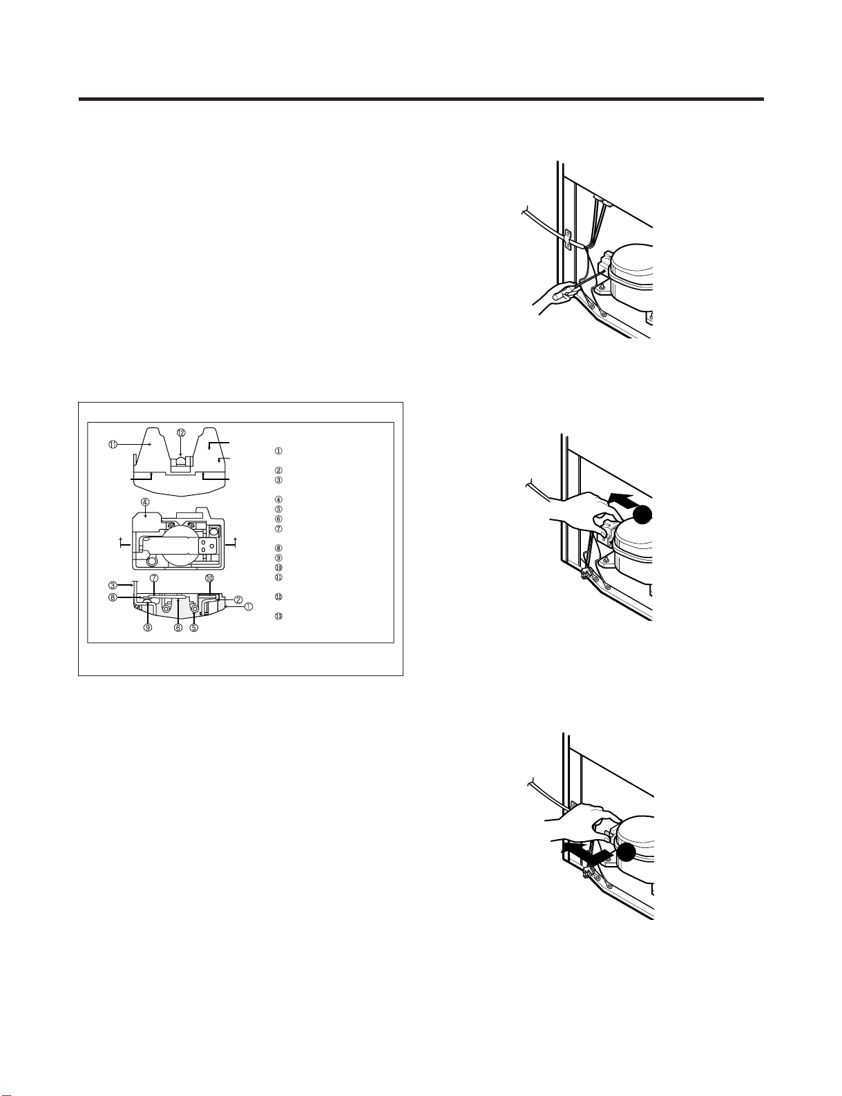
4-4 TO REMOVE THE COVER PTC
1) Remove the Cover Back M/C.
(2) Remove the screw on Cover PTC.
(3) Remove two Housings on upper part of Cover PTC.
(4) Take out the cover PTC from upper to lower position
like .
(5) Turn 45° in the direction of and take it out.
(6) Assembly in reverse order of disassembly.
- 11 -
Part
Customer part
number
Lot code/
date code
330 FBYY -S1 BOX98
12345678
Physical
termination
part number
Electrical
characteristics
part number
No. Name
Base, phenolic
(UL 94 V-0 rated)
Movable arm support, plated steel
Stationary contact support,
plated steel
Heater support, plated steel
Heater, resistance alloy
Disc, thermostatic alloy
Movable arm, spring temper
copper alloy
Contact, movable, silver on copper
Contact, stationary, silver on copper
Slug, plated steel
Cover, polyester
(UL 94 V -0 rated)
Pin connector, plated copper alloy
(To engage 2.33/2.66 mm dia. pin)
Quick-connect terminal, brass,
conforms to UL 310, MEMA
DC-2, DIN 46344
(OVERLOAD PROTECTOR cross section)
Figure 13
1
2
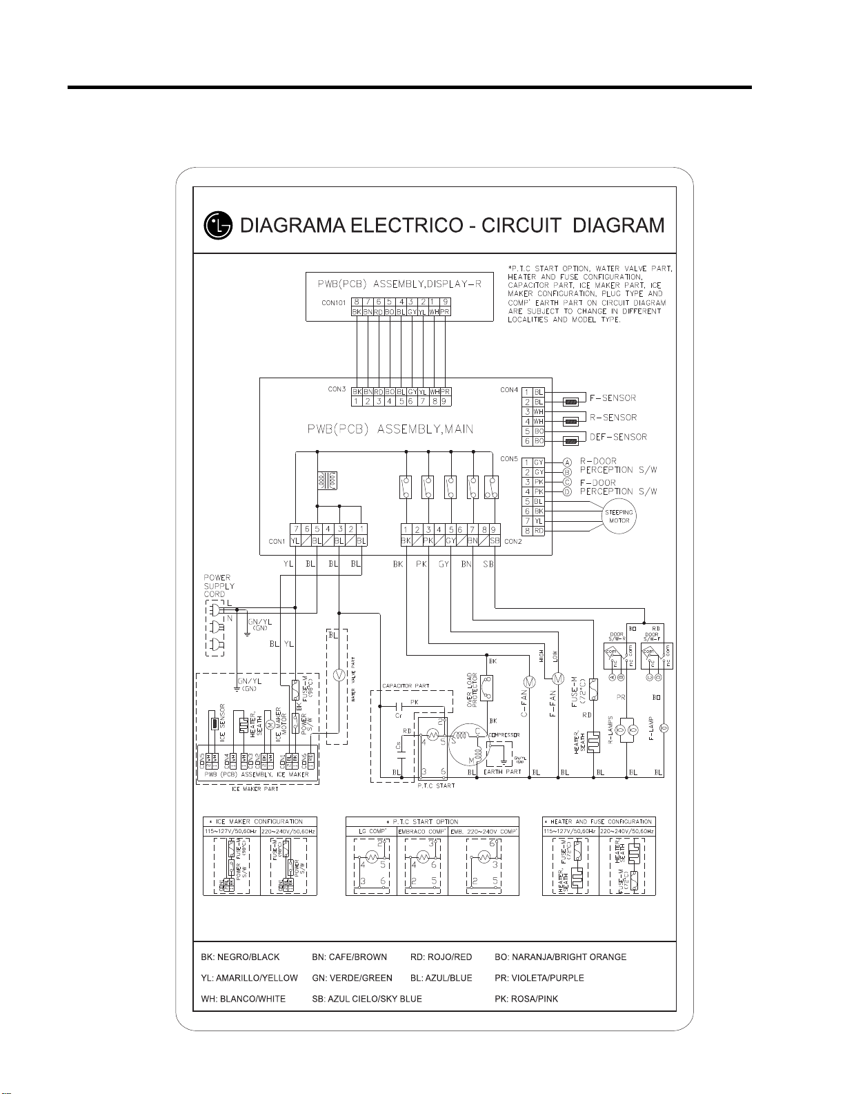
GY: GRIS/GRAY
Best / Best dispenser
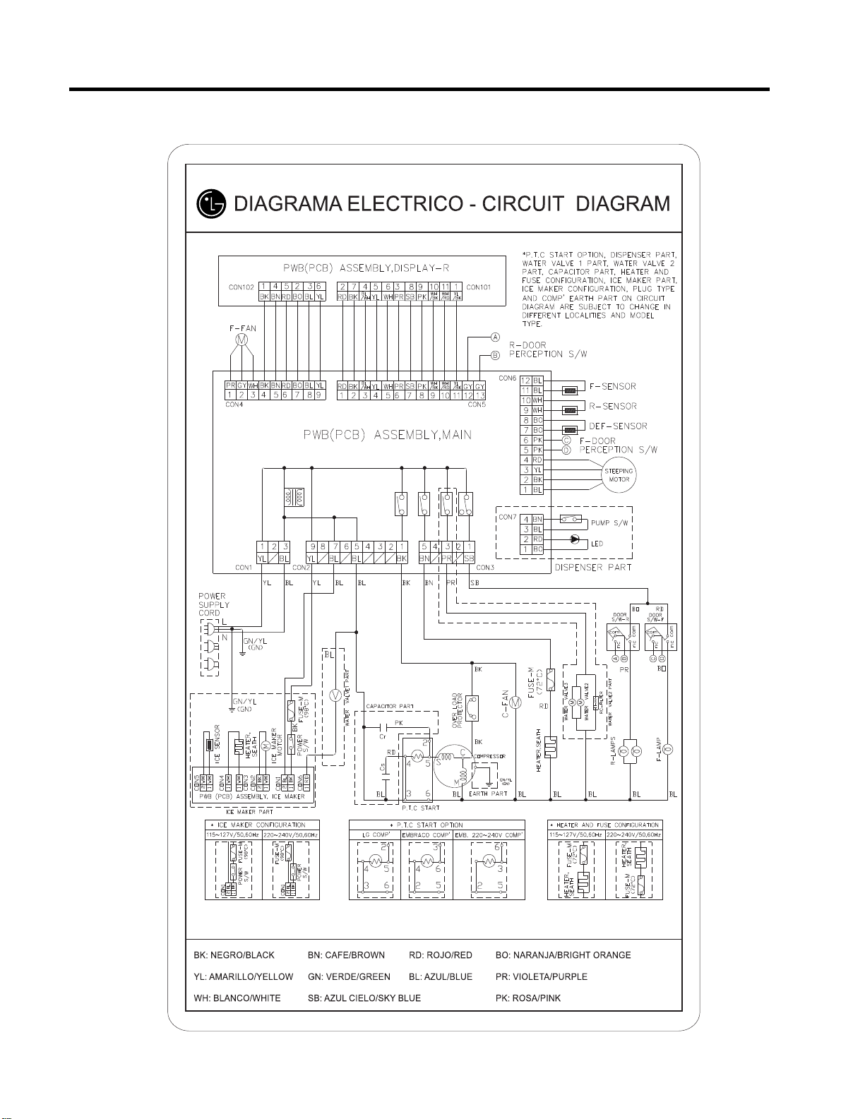
5. CIRCUIT DIAGRAM
5. CIRCUIT DIAGRAM
- 12 -
GY: GRIS/GRAY
Good / Better
- 13 -

6. TROUBLESHOOTING
- 14 -
6-1 COMPRESSOR AND ELECTRIC COMPONENTS
1
2
3
4
5
2
5
5
3
5
4
5
5
1
43
YES
YES
The range of resistance is between 1~50Ω (OK)
Not open
4.5~9 Ω
Open
Open or short
Open or short
YES
YES
NO
NO
Power Source.
No Voltage.
(Reated Voltage
±10%)?
Replace OLP.
Reconnect.
Replace
PTC-Starter.
Replace OLP.
Did
compressor
start?
Compressor
is OK
Replace the
compressor
Check connection
condition.
OLP disconnected?
Advise customer that
power supply needs to be
checked by an electrician.
Replace
Compressor.
Supply
voltage rating
with ±10%.
Applied voltage isn't
in range of Rating
Voltage ±10%.
Remove PTC-Starter
from Compressor and
measure voltage
between Terminal C of
Compressor and
Terminals 5 or 6 of PTC.
Check resistance
between M-C, S-C and
M-S in Motor
Compressor.
Check resistance of
two terminals in
PTC-Starter.
Check resistance of two
terminals in OLP.
Check the power supply
under load.
(Compressor attempting
to re-start after being off
for 5 minutes).
Check
resistance of
Motor
Compressor.
Check
resistance of
PTC-Starter.
Check OLP.
Check
starting state.
NO
- 15 -
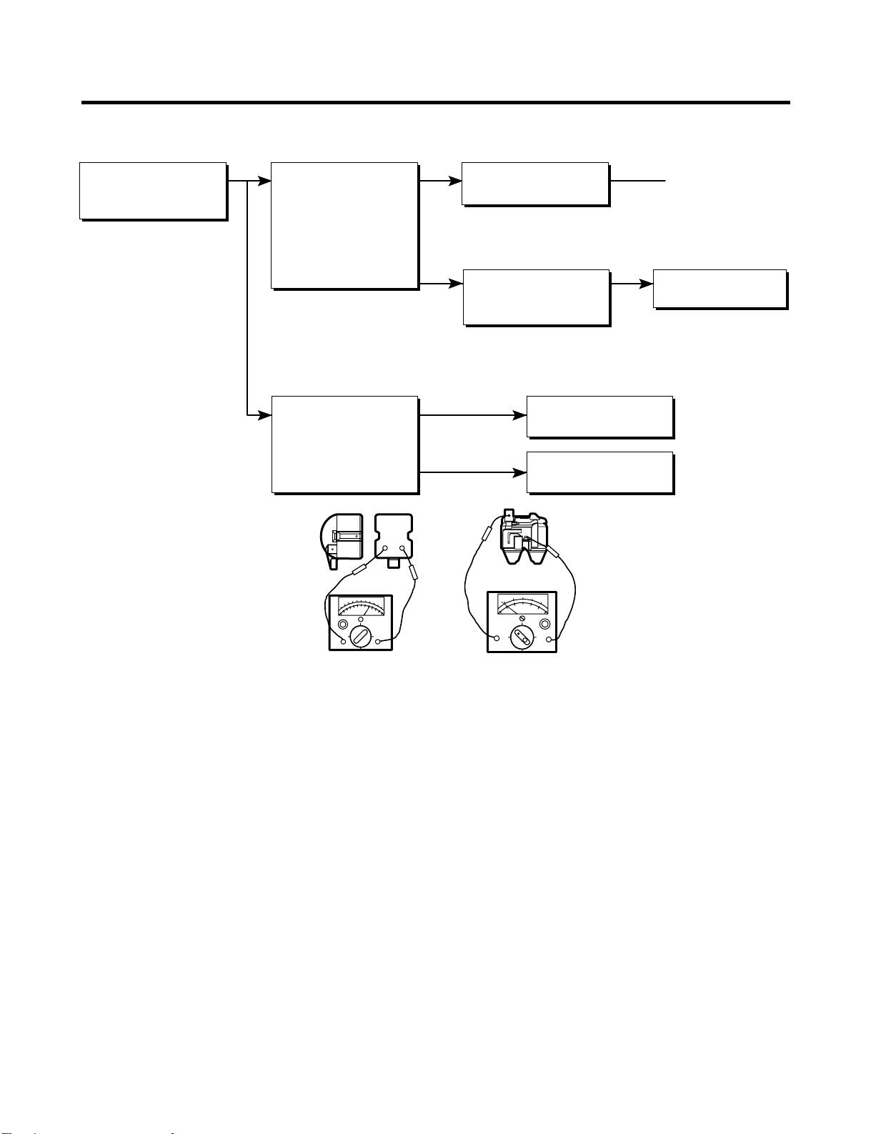
6-2 PTC AND OLP
65
Shows continuity
Open
Normal operation of
Compressor is
impossible or poor.
Separate PTC-Starter
from Compressor and
measure resistance
between No. 5 and 6
of PTC-Starter with a
Tester.
(Figure 14)
Separate OLP from
Compressor and check
resistance value
between two terminals
of OLP with a Tester.
(Figure 15)
Observation value is
115V/60Hz : 6.8Ω±30%
The resistance value
is 0Ω (short) or
∞ (open).
Check another
electric component.
Replace OLP.
Replace PTC-
Starter.
Figure 14
Figure 15
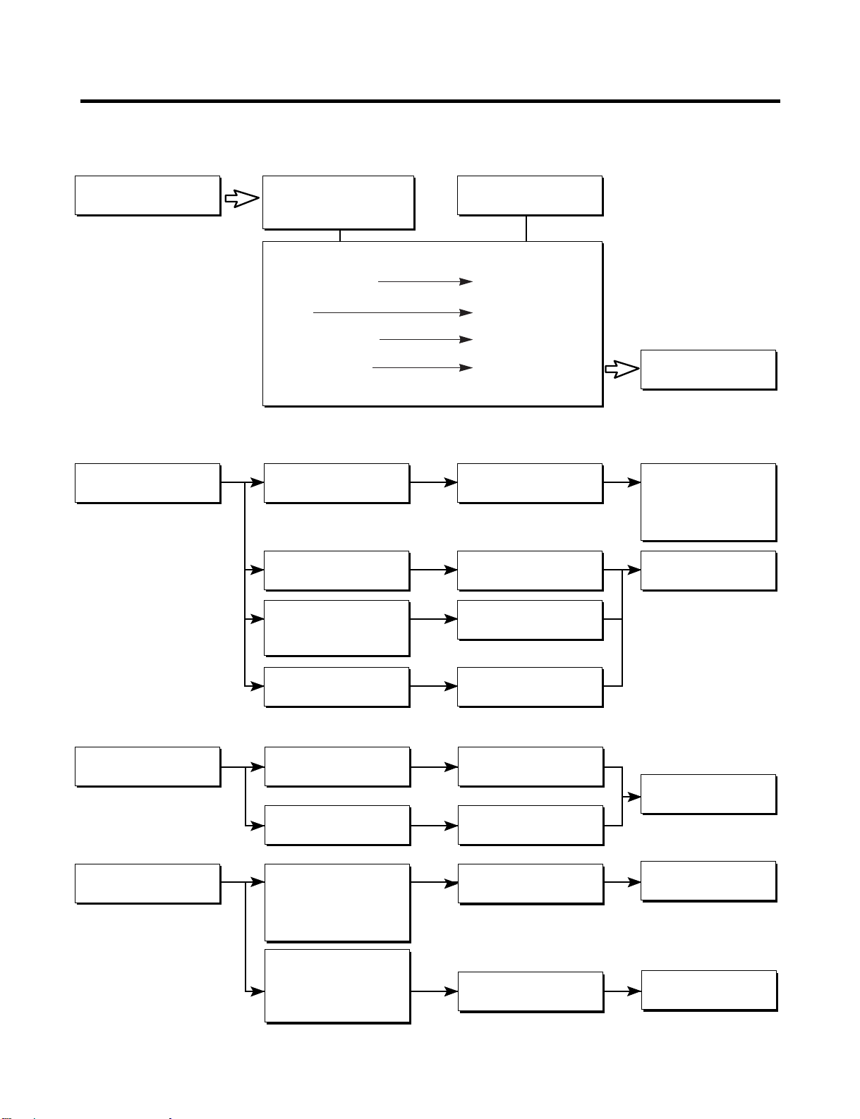
- 16 -
▼ Not cooling at all
▼ Poor cooling performance
Compressor
doesn't run.
Compressor runs
poorly.
Check starting
voltage.
Check for open short or
incorrect resistance readings
in the following components
a. Starting devices
b. OLP
c. Compressor coil
d. Wiring harness
Low voltage.
Short, open, or broken.
Poor contact
or shorted.
Coil open or shorted.
Poor contact
or shorted.
Poor or broken or
open contact.
Shorted.
Lack of capacity.
Replace
indicated component.
Advise customer that
the Power supply
needs to be checked
by an electrician.
Replace
indicated component.
Cause
Check voltage at
starting devices.
Check current flowing
in sub-coil of
Compressor.
Check rating of OLP.
Fan motor
doesn't run.
Heavy frost buildup on
EVAPORATOR.
Wire is open or
shorted.
Coil is shorted
or open.
Open.
Open.
Replace
Defrost Heater.
Replace
indicated component.
Replace
indicated component.
Check wiring circuit.
Check Fan Motor.
Check current flow in
the following
components:
Sensor
Fuse-M
Check current flow in
the Defrost Heater.
6-3 OTHER ELECTRICAL COMPONENTS

6-4 SERVICE DIAGNOSIS CHART
- 17 -
COMPLAINT POINTS TO BE CHECKED REMEDY
● Other possible problems:
Check if frost forms in
the freezer.
Check Components
of the defrosting
circuit.
Check the
refrigeration system.
Check the
Thermistor.
Not
defrosting
The system
is faulty.
Perform sealed
system repair.
Replace the
Thermistor.
The operation of
the Thermistor is
incorrect.
No Cooling.
Cools poorly.
Foods in the
Refrigerator
are frozen.
Condensartion or ice
forms inside
the unit.
Condensartion forms
in the Exterior Case.
There is abnormal
noise.
Door does not
close well.
Ice and foods
smell unpleasant.
• Is the power cord unplugged from the outlet?
• Check if the power switch is set to OFF.
• Check if the fuse of the power switch is shorted.
• Measure the voltage of the power outlet.
• Check if the unit is placed too close to the wall.
• Check if the unit is placed too close to the stove,
gas cooker, or in direct sunlight.
• Is the ambient temperature too high or
the room door closed?
• Check if food put in the refrigerator is hot.
• Did you open the door of the unit too often
or check if the door is sealed properly?
• Check if the Control is set to Warm position.
• Is food placed in the cooling air outlet?
• Check if the control is set to colder position.
• Is the ambient temperature below 41°F(5°C)?
• Is liquid food sealed?
• Check if food put in the refrigerator is hot.
• Did you open the door of the unit too
often or check if the door is sealed properly?
• Check if the ambient temperature and humidity
of the surrounding air are high.
• Is there a gap in the door gasket?
• Is the unit positioned in a firm and even place?
• Are any unnecessary objects placed
in the back side of the unit?
• Check if the Drip Tray is not firmly fixed.
• Check if the cover of the compressor enclosure
in the lower front side is taken out.
• Check if the door gasket is dirty with
an item like juice.
• Is the refrigerator level?
• Is there too much food in the refrigerator?
• Check if the inside of the unit is dirty.
• Are foods with a strong odor unwrapped?
• The unit smells of plastic.
• Plug into the outlet.
• Set the switch to ON.
• Replace the fuse.
• If the voltage is low, correct the wiring.
• Place the unit about 4 inches (10 cm) from the wall.
• Place the unit away from these heat sources.
• Lower the ambient temperature.
• Put in foods after they have cooled down.
• Don't open the door too often and close
it firmly.
• Set the control to Recommended position.
• Place foods in the high-temperature section.
(front part)
• Set the control to Recommended position.
• Set the control to Warm position.
• Seal liquid foods with wrap.
• Put in foods after they have cooled down.
• Don't open the door too often and close
it firmly.
• Wipe moisture with a dry cloth. It will disappear
in low temperature and humidity.
• Fill up the gap.
• Adjust the Leveling Screw, and position the
refrigerator in a firm place.
• Remove the objects.
• Fix the Drip Tray firmly in the original position.
• Place the cover in its original position.
• Clean the door gasket.
• Position in the firm place and level the
Leveling Screw.
• Make sure food stored in shelves does not prevent
the door from closing.
• Clean the inside of the unit.
• Wrap foods that have a strong odor.
• New products smell of plastic, but this
will go away after 1-2 weeks.
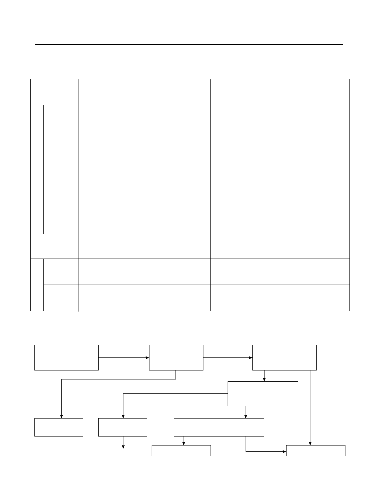
6-5 REFRIGERATION CYCLE
- 18 -
▼ Troubleshooting Chart
▼ Leakage Detection
YES
YES
Check if compressor
runs.
Check if frost
forms in
Evaporator.
Observe the discharged
amount of Refrigerant.
Inject refrigerant in compressor
and check cooling operation.
Clogged by dust. Gas leakage.
Faulty
Compressor.
Moisture Clog
Check if oil
leaks.
Frost formed normally
Normal amount
None or too much
(Find the leak and repair it)
Frost formed normally
No frost
or frost forms
in inlet only
Check Compressor
PARTIAL Freezer Low flowing sound of A little higher • Refrigerant level is low due
LEAKAGE compartment and Refrigerant is heard and than ambient • to a leak.
Refrigerator don't frost forms in inlet only. temperature. • Normal cooling is possible by
cool normally. • restoring the normal amount of
• refrigerant and repairing the leak.
COMPLETE Freezer Flowing sound of refrigerant Equal to ambient • No discharging of Refrigerant.
LEAKAGE compartment and is not heard and frost isn't temperature. • Normal cooling is possible by
Refrigerator don't formed. • restoring the normal amount of
cool normally. • refrigerant and repairing the leak.
PARTIAL Freezer Flowing sound of refrigerant A little higher • Normal discharging of the
CLOG compartment and is heard and frost forms than ambient • refrigerant.
Refrigerator don't in inlet only. temperature. • The capillary tube is faulty.
cool normally.
WHOLE
Freezer
Flowing sound of refrigerant Equal to ambient • Normal discharging of the
CLOG
compartment and
is not heard and frost isn't temperature. • Refrigerant.
Refrigerator don't cool.
formed.
MOISTURE Cooling operation Flowing sound of refrigerant Lower than • Cooling operation restarts
CLOG stops periodically. is not heard and frost melts. ambient • when heating the inlet of the
temperature. • capillary tube.
COMP- Freezer and Low flowing sound of A little higher • Low pressure at high side
RESSION Refrigerator refrigerant is heard and ambient • of compressor due to low
don't cool. frost forms in inlet only. temperature. • refrigerant level.
NO COMP- No compressing Flowing sound of refrigerant Equal to ambient • No pressure in the high
RESSION operation. is not heard and there is temperature. • pressure part of the
no frost. • compressor.
CAUSE
TEMPERATURE
OF THE
COMPRESSOR
REMARKS
STATE OF
THE UNIT
STATE OF THE
EVAPORATOR
LEAKAGE
CLOGGED BY DUST
DEFECTIVE
COMPRESSION
● Observe the discharging point of the refrigerant, which may be in the oil discharging part of the compressor and in a hole
in the evaporator.

- 19 -
NO. ITEMS UNIT STANDARDS PURPOSES REMARKS
▼ General Control of Refrigerating Cycle
Pipe and
piping system
opening time
Welding
N
2 sealed
parts
Refrige-
ration
Cycle
Refrigerant
weighing
Drier
replacement
Leak check
1
2
3
4
5
6
7
Min.
Nitrogen
pressure
Confirm
N
2 leak
Min.
Torr
EA
EA
EA
EA
Pipe: within 1 hour.
Comp: within 10 minutes.
Drier: within 20 minutes.
Weld under Nitrogen
atmosphere.
(N
2 pressure:
0.1~0.2 kg/cm
2
)
Confirm the sound of
pressure relief when
removing the rubber cap.
Sound: usable
No sound: not usable
More than 40 minutes
Below 0.03 (ref)
High and low pressure sides
are evacuated at the same
time for models above 200 l.
Use R-134a manifold
exclusively.
Use R-134a manifold
exclusively.
R-134a manifold exclusively.
R-134a manifold exclusively.
Use R-134a exclusively.
Weighing allowance: ±5g
Note: Winter: -5g
Summer: +5g
- Use R-134a exclusively for
R-134a refrigerator.
-
Replace drier whenever repairing
refrigerator cycle piping.
- Do not use soapy water for
check. It may be sucked
into the pipe by a vacuum.
To protect
moisture
penetration.
To protect oxide
scale formation.
To protect
moisture
penetration.
To remove moisture.
To protect mixing
of mineral and
ester oils.
To protect R-12
refrigerant mixing.
To protect R-12
refrigerant mixing.
To protect R-12
refrigerant mixing.
Do not mix with
R-12 refrigerant.
To remove the
moisture from
pipe inside.
Defect in
refrigerant leak
area.
The opening time should be reduced
to a half of the standards during rain
and rainy seasons (the penetration of
water into the pipe is dangerous).
- Refer to repair note in each part.
- R-134a refrigerant is more
susceptible to leaks than R-12 and
requires more care during welding.
-
Do not apply force to pipes before and
after welding to protect pipe from cracking.
- In case of evaporator parts, if it doesn't
make sound when removing rubber
cap, blow dry air or N
2 gas for more
than 1 min. and than use the parts.
Note: Only applicable to the model
equipped with reverse flow
protect plate.
Vacuum efficiency can be improved
by operating compressor during
evacuation.
The rubber pipes for R-12 refrigerant
will be melted when they are used for
R-134a refrigerant (causes of leak.)
- Do not weigh the refrigerant at too
hot or too cold an area.
(77°F [25°C] is adequate.)
- Make Copper charging canister
(Device filling refrigerant)
Socket: 2SV Plug: 2PV R-134a
Note: Do not burn O-ring (bushing)
during welding.
- Check for an oil leak at the refrigerant
leak area. Use an electronic leak
detector if an oil leak is not found.
- The electronic leak detector is very
sensitive to halogen gas in the air. It
also can detect R-141b in urethane.
Practice many times before using this
type of detector to avoid false readings.
Evacuation
time
Vacuum
degree
Vacuum
Vacuum
piping
Pipe
coupler
Outlet
(Socket)
Plug
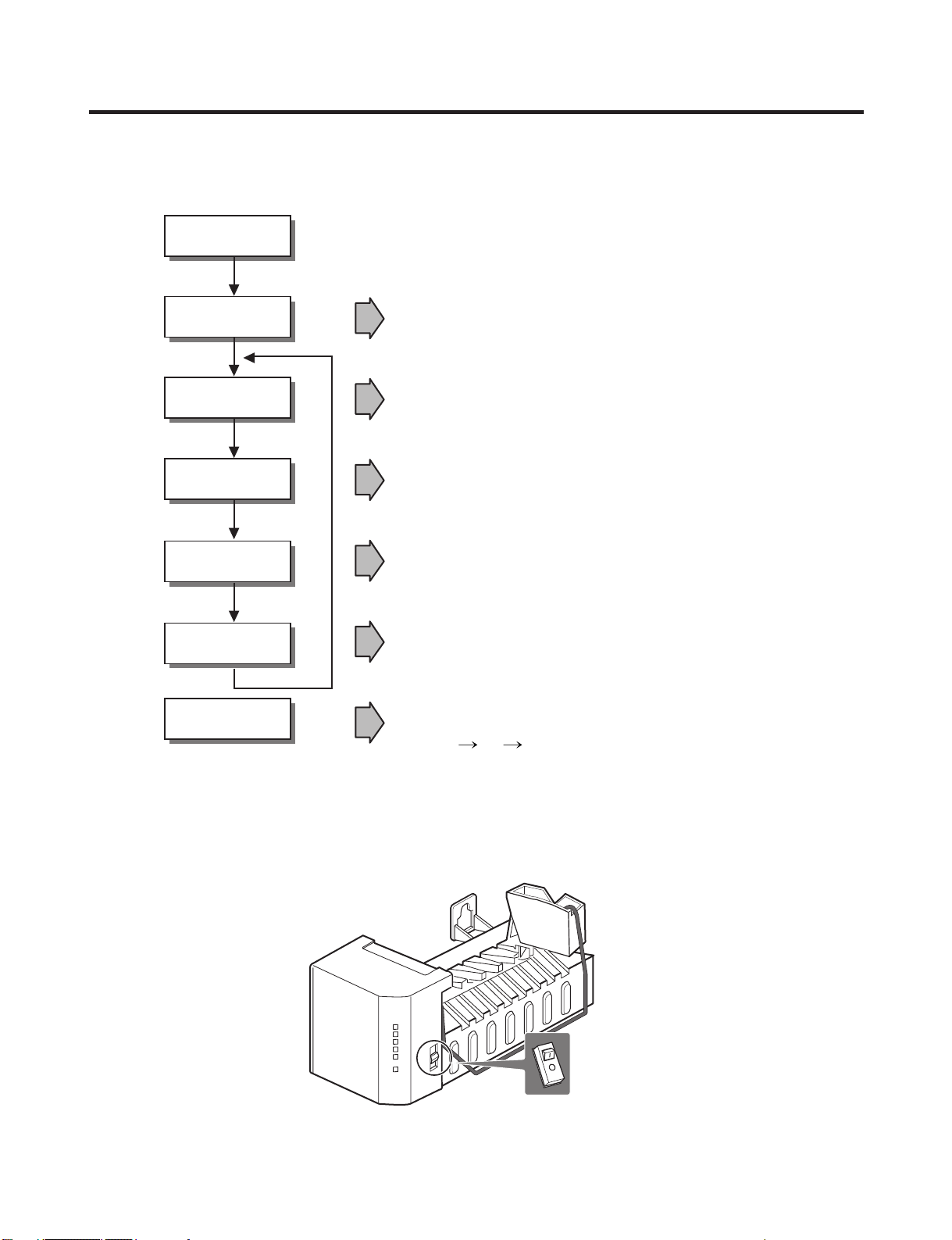
7-1 OPERATION PRINCIPLE
7-1-1 Operation Principle of IceMaker
1. Turning the Icemaker stop switch off (O) stops the ice making function.
2. Setting the Icemaker switch to OFF and then turning it back on will reset the icemaker control.
7. OPERATION PRINCIPLE AND REPAIR METHOD OF ICEMAKER
- 20 -
• Adjusts EJECTOR to Start Position with power on.
Power On
Start Position
Ice Making
Mode
Harvest
Mode
Park Position
Fill
Test Mode
• Waits until water becomes cold after starting the
ice making operation.
• Runs MOTOR to drop ice from the tray the ICE BIN.
• Performs Ice Making Mode after supplying water by operating
the SOLENOID in ICE VALVE.
• To operate LINE and SERVICE, press and hold the Fill Key
for 3 seconds. The ice maker will run through 3 stages:
Harvest Fill Icemaking.
• With the detect lever, checks if the ICE BIN is full.

7-2 CONTROL METHOD ACCORDING TO FUNCTIONS
7-2-1 Start Position
1. After POWER OFF or Power Outage, check the EJECTOR's position with MICOM initialization to restart.
2. How to check if it is in place:
- Check HIGH/LOW signals from HALL SENSOR in MICOM PIN.
3. Control Method to check if it is in place:
(1) EJECTOR is in place,
- It is an initialized control, so the mode can be changed to ice making control.
(2) EJECTOR isn't in place:
A. If EJECTOR is back in place within 2 minutes with the motor on, it is being initialized. If not, go to Step B.
B. If EJECTOR is back in place within 18 minutes with the heater on (to control Heater on its OFF condition), it is being
initialized. If not, it is not functioning. Repeat Step B with Heater and Motor off.
7-2-2 Ice Making Mode
1. Ice Making control refers to the freezing of supplied water in the ice trays. Complete ice making operations by measuring
the temperature of the Tray with Ice-Making SENSOR.
2. Ice Making starts after completing fulfilled ice control and initial control.
3. The Ice Making function is completed when the sensor reaches 19°F(-7°C), 60 to 240 minutes after starting.
4. If the temperature sensor is defective, the ice-making function will be completed in 4 hours.
7-2-3 Harvest Mode
1. Ice-removing control refers to the operation of dropping cubes into the ice bin from the tray when ice-making has
completed.
2. Ice removing control mode:
(1) Operates Heater for 30 seconds; then operate MOTOR.
(2) After performing Step 1 (to control the Heater on its off condition), Ice-Removal control will be back in place wthin 18
minutes. (Hall SENSOR sign = OV). Ice removal is then complete. Then change the mode to the water supply control.
If this control phase fails to start, it is not functioning. Put the Heater and Motor in the off position. Restart every 2
hours. (Refer to fig.1)
NOTE : If the motor malfunctions and starts before the detect lever rises, MICOM regards the Ice-Removing phase as
completed. Water then starts flowing. To prevent this, MICOM doesn’t switch to water-supply mode, but restarts the ice-
removing mode. If this happens 3 times, the motor is malfunctioning and you should stop the loads (Heater, Motor). Then
restart the Ice-Removing mode every 2 hours. (See Step 2 above.)
- 21 -
Heater
on
off
on
0V
5V
off
30 sec.
10 sec.
Motor
Hall IC
Ice removing
completion point
2 ms
Ice making sensor temperature is 50°F(10˚C)
or more
Max. 18 minutes
After detect LEVER rises
<fig1. Ice removing process>
 Loading...