


LG GBB530***Q Series, GBB530***P Series, GBB539 Series, GBF539 Series, GBB530***M Series Service Manual
...
http://biz.lgs ervice.com
R E FR IG E R ATOR
SER VIC E MANUA L
C AUT ION
B E FOR E S E R V IC ING T HE UNIT, R E AD T HE " S A FE TY
P R E CA U T IONS " IN T HIS MA NUA L .
GBB532****
GBB530****
MODE L :
R ef. No .R ef. No .
GBB531****
GBB539****
Ref. No.
GBF539****
Re f. N o.
GBF530 *** *
C OL OR :

C ONT E NTS
S AF E TY P R E C A UTIO NS ......................................................................................................... ... ........................................... 2
S E R VIC ING P R E C AU TION S ................................................................................................................................................... 3
S PE CIF ICA T IO NS ............................................................................................................. ...................................................4-7
P A RT S IDE NT IFIC ATION .......................................................................................................... .........................................8-12
INS TR UC TION S F OR R E V E R S ING DOO R S WING ......................................................................................... ...............13-15
DIS AS S E MB LY ................................................................................................................... .............................................. 16-17
DO OR .......................................................................................................................... ......................................................16
DO OR S WIT CH ................................................................................................................... ..............................................16
F AN AND F AN MO T OR ............................................................................................................. ........................................16
DE F ROS T C ONTR OL AS S E MBLY ...................................................................................................... .............................17
F R E E ZE R HE AT E R, S HE ATH ..................................................................................................... ... ..................................17
D JU S T ME NT .................................................................................................................... ............................................. 18-19
A
C O MPRESS OR (A + + and A s ) ledoM + ..................................................................................... .................................. ..18
P T C- STA RTE R (A++ a nd A+ Mo del s) .................................................................................... .. . ..................................18
O LP (O VER L OAD PRO T EC TOR ) (A++ a nd A + Mo del s ) ...................................................... . . ..................................19
C OMP R ES S OR ................................................................................................................. ................................................20-28
INVE R TE R L IN E AR COMP R E SSOR . ................................................................................................... .......................20-28
HE A VY R E PAIR ME TH OD OF R E FR IG E RA T O R B Y AP PL IC AT ION OF R E
OUT LINE ..................................................................................................................... .. .....................................................29
HE AVY R E P AIR S V C ME T HOD ....................................................................................................... .......................... .30-34
C IR CUIT DIA GR AM ............................................................................................................... ...........................................35-4
TR OU BL ES HO OTING (ME C HA NIC AL P AR T) ............................................................................................. ....................4-49
COMPRESS OR AND ELECTRIC COMPONENTS ........................................................................................ . ....................... ..4
PTC AN D OLP .............................................................................................................................. .............. .........................4
ANOTHE R E LE C T RIC C OMP ONE NTS ................................................................................................... .........................4
S E R VIC E DIAG NOS IS C HAR T ....................................................................................................... ...............................
R E FR IG E R ATING CY CL E ........................................................................................................ ... ............................... .4-
MIC OM F UN C TION & PC B C IR C UIT E XP L ANA T IO N ...................................................................................... ..............5-5
MIC OM E R R OR C ODE ..............................................................................................................
P C B P IC TUR E ................................................................................................................ ... .............................................. .5-6
TR OU BL ES HO OTING WIT H E R R OR DIS PLAY ............................................................................................ .................6-7
TR OU BL ES HO OTING WIT HOUT E R R OR DIS P L AY ......................................................................................... .............7-8
R E FE R E NC E ..................................................................................................................... ................................................8-8
E XP LODE D V IE W &R E PL AC EME NT P AR T S L IS T ......................................................................................... ...............8-
F R IG ER ANT ................................... ...... ..29-34
.. .4
.......................................5-5
S AF E T Y P R E C A UT IONS
P lea se read the following instructions before servicing your
refrigerator.
1. Check the s et for electric los ses.
2. Unplug prior to s ervicing to prevent electric s hock.
3. Whenever testing with power on, wear rubber gloves to
preve nt electric s hock.
4. If you use any kind of applianc e, check regular current,
voltage a nd capacity.
5. Don't touch meta l products in the fre ez er with we t
hands . This ma y ca us e fros tbite.
6. Prevent water from following onto electric eleme nts in
the me cha nical par
7. Whe n s tan ding up a fter ha ving c hecked the lowe r
s ection of the refrige ra tor with the uppe r door open,
move with care to avoid hitting the upper door.
ts.
8. When tilting the s et, remove any materials on the set,
es pecially the thin plates(ex. Glas s s helf or books.)
9. When s ervicing the e vaporator, wear cotton gloves.
10. L eave the disas s embly of the refrigerating cycle to a
s pecialized servic e ce nter. T he ga s ins ide the circuit
may pollute the environment.
11. W hen you discharge the refrigerant, wea r the protective
safety glasses or goggle for eye s afety.
12. W hen you repair the c yc le sys tem in refrige ra tor, the
work area is well ventilated.
E specially if the refrigerant is R 600
hea t s ources . (No s moking)
- 2 -
S E R VIC ING P R E C A UT IONS
F eature s of refrigerant (R 600a)
• Achromatic and odor less gas.
• Flamma ble gas and the ignition (explos ion) a t 494°C .
• Upper/lowe r explos ion limit: 1.8% ~8.4% /V ol.
F eature s of the R 600a refrigerato r
• C harging of 60% refrigerant compared with a R134a model.
• The s uction pre ssure is below 1bar (abs) during the operation.
• Becaus e of its low suction pressure, the external air may ow
in the cyc le s ystem when the refrigera nt lea k, and it causes
malfunc tion in the compressor.
• The dis placement of compressor using R 600a mus t be at
least 1. 7 times la rger than that of R 134a.
• Any type of drye r is applicable (X H-5, 7, 9).
• The E VAP OR AT OR or any other cycle part that has welding
joint is hidde n in the foam. ( If not hidden inside, the whole
ele ctric parts mus t be tes ted with the LE AK AG E T E S T
according to the IE C S ta ndard.)
• The compressor ha s label of the refrigerant R 600a.
• Only the S VC ma n must have an access to the system
.
Ins tallation place
• Mus t be well ventilated.
• Mus t be 20 m
• Mus t be no-s moking area.
• No ignitable fa ctors must be pres ent.
3
or la rger.
Utilities
• R efrigerant cylinder (MAX NE T 300g)
• Ma nometer
• V acuum pump (600
• P iercing C lamp
• Quick coupler
• Hoses (5m-1E A, 1m-3E A)
• LOKR IN
• P orta ble Leakage detector (3g/year
• Nitrogen cylinder (for leakage tes t)
• C oncentration gauge
G
ℓ /min)
)
After the refrigerant (R 600a) is completely discharged,
repair any defective parts a nd replace the drye r. At any
case you must us e the LOK R ING for connecting or replac ing
any part in the cycle (No F ire, N o W elding). C harge the N2
gas in order to check for leakage from welding points and the
LOK R ING . If lea kages are found, repair the defects again.
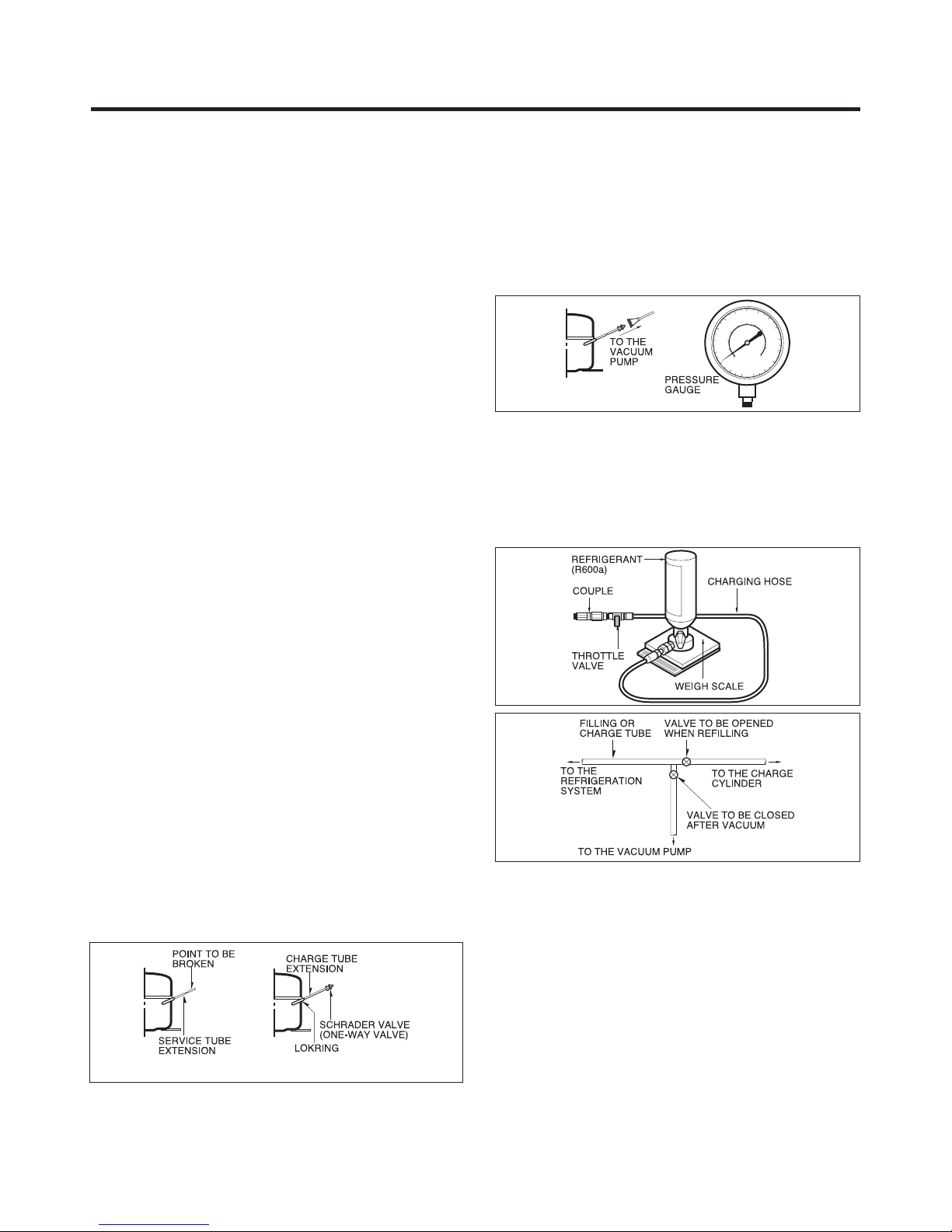
C onnect the S chra der va lve to pump with the couple
then turn the pump on for vacuum s tate (Figure 3). L et the
pump run until the low pressure ga uge indica tes the vacuum
(gauge pressure -1a tm or -760mmHg, absolute pressure 0 ).
R ecommended vacuum time is 30 min.
r. And
F igur e 3
After the sys tem is co mpletely va cuume d, ll it with the
re frige ra nt R 600a up to what has been specie d a t y our
refrige rator Na me P late. T he amount of refrige rant (R 600a)
mus t be precis ely me as ure d within the error
electron s cale ( F igure 4).
If you use the manifold connected with both the refrige rant
(R 600a) cylinder and the vacuum pump s imultaneous ly, make
sure the pump valve is closed (F igure 5).
of ±2g by an
Make s ure before Servic ing
• R efrigerant
C onrm the refrigerant by checking Name P late and the label
on the compressor, after opening the C OVE R ASSE MB LY ,
B AC K -M/C .
• If the refrigerant is R 600a, you mus t not weld or apply a heat
source.
Air R echa rging in C ompressor
B efore relling the refrige rant, you mus t perform the te st
according to C hapter 5 (T R OU BL ES HOOT ING C HAR T). When
the de fects are found, yo u mu s t dis cha rge the re s idua l
re frig e ra nt ( R 600a ) in the ou tdoor. F or di s cha rg in g the
refrigerant R 600a, break the narrow portion of tube extens ion
by hand or with a pipe cutte r as shown in Figure 1. Lea ve it for
30min in outside to s tabilize the pressure with ambient. The n,
chec k the pressure by pie rcing the drye r part with pierci
pliers. If the refrigerant is not completely dis cha rged, let the
refrigerator alone for more 30min in outside.
F igur e 1 F igur e 2
Atta ch the service tube installed with a S chra der valve (oneway valve) by using the LOK R ING (F igure 2). T hen, conne ct
the S chr a der v alve (one-wa y v a lve ) to the pump tha t is
connected to the dis charging hos e leading to the outside .
When dis cha rging the residual refrigerant, repeat 3 cycle that
includes 3min of the pump running->pump o->30s ec
compressor running.
ng
of the
F igur e 4
C onne c t the c ha rgin g hos e (tha t is c onne cte d to the
refrige rant (R 600a) cylinder) to the S chra der valve ins talled
on the service tube. Then, charge the refrigerant (R 600a) by
controlling the T hrottle va lve. W hen you
open the Throttle valve because it may make damage to the
compressor. Gra dua lly cha rge the refrige rant (R 600a ) by
cha nging open and close the Throttle Valve (5g a t ea ch time).
The cha rging hose must use a one-wa y valve to prevent the
refrigerant reuence. C lose the S chrader valve cap after the
refrigerant ( R 600a) is completely re cha rged.
Afte r you completely re ch a rge the re frige ra nt (R 600a ),
perform the leakage test by using a porta b
or s oa py wa ter. T es t the low pre ssure (s uc tion) pa rts in
compre ssor o time and high pressure parts in compressor
on time. If the leakages are found, resta rt from the refrigera nt
(R 600a) disc harging process and repa irs de fects of leaks.
After the leakage test, che ck the tempe rature of e ach pa rts of
the cycle . C heck with ha nds if the C ON DE NS E R a nd the
ca se (H O T -LINE pipe) that is contacted to the door gasket
are warm. C onrm that fros t is unif
surface of the EVAP OR ATOR .
do s o, do not fully
le leakage detector
orm dis tributed on the
- 3 -
F igur e 5
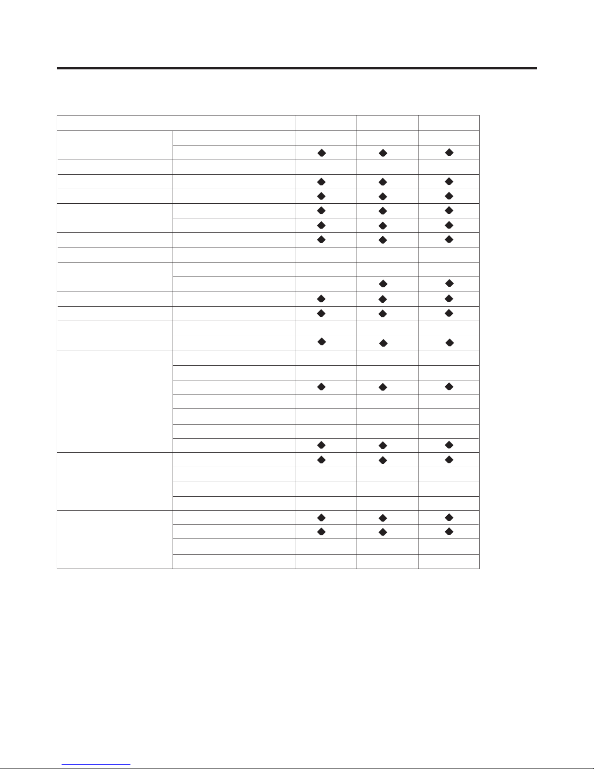
S P E C IFIC ATIONS
•
G B B530***Q*
•
G B F530***Z*
•
G B B530***Z*
•
G B B530***X*
•
530*** P*
G B F
•
G B B 530***W*
•
•
•
•
-
-
•
•
-
-
•
-
-
•
-
-
•
-
-
•
•
•
•
•
•
•
•
•
•
•
•
•
•
•
•
67g
67g (FLA102)
61g (BMG089)
67g (FLA102)
61g (BMG089)
67g
67g (FLA102)
61g (BMG089)
63g (CMA089)
-
180cc(FLA102)
180cc(FLA102)
-
180cc(FLA102)
150cc(CMA089)
-
-
175cc(FLB124)
-
-
170cc(BMG089)
-
-
170cc(BMG089)
-
175cc(FLB124)
- -
Yes(CMA089)
170cc(BMG089)
No (FLA102/BMG089)
•
•
•
•
•
•
2E A
-
-
-
-
3E A
3E A
•
-
•
3E A 2E A
•
•
•
•
-
•
-
-
- -
•
•
•
•
•
•
•
•
•
•
•
•
•
•
•
•
•
•
-
•
•
•
•••
•••
•
•
•
3E A
3E A
3E A
•
3E A
•
3E A
•
•
-
-
•
•
•
•
-
•
•
•
•
•
-
•
•
•••
•
-
•
-
•
-
•
-
-
•
•
•
•
•
•
-
-
•
-
57g (BMG089)
61g (CMA089)
•
150ccCMA089)
170cc(BMG089)
-
•
•
-
•
3E A(option 2)
•
•
•
- -
•
•
(option )
-
•
•
- -
4E A
•
-
G B B 530***P*
G B B 530*** F*
IT EMS
•
•
-
-
•••••••
•
67g (FLA102)
61g (BMG089)
63g (CMA089)
180cc(FLA102)
150cc(CMA089)
170cc(BMG089)
-
Yes(CMA089)
No (FLA102/BMG089)
•
-
-
3E A
-
- -
•
•••
-
3E A
-
•
•
•
•
-
•
•
-
67g (FLB124)
65g (FMA102)
-
175cc(FLB124)
-
-
120cc(FMA102)
•
•
-
•••••••••
-
3E A(option 2)
•
•
(option )
-
•••
-
3E A
•
-
(2E A)
5 HFP
P T C S tarting T ype
P in Tube Type
S piral C ondenser
Wire C ondenser
R emovable G la s s S helf
Vita, L E D(1E A)
C over, T V (L )
C over, T V (U )
F res h 0 Zone
Magic C risper (1E A)
Vegetable Drawer (1E A)
Foldin g S h e lf
F an C ooling
Micom Control
F ull Automatic
Heater Defros t
Heater, S heath
R 600a
H T S 55 MT
595(W) X 2010(H) X 650(D)
595(W) X 1900(H) X 650(D)
S5 H FP
Bottl e Rac k
E gg T ray
Da iry C orner
B asket
Water T ank
Tray Drawer (3E A)
Tray Ice
Ice B ox
Wire S helf
DE F ROS TING S YS TE M
NE T WE IGHT
C OOLING S YS T E M
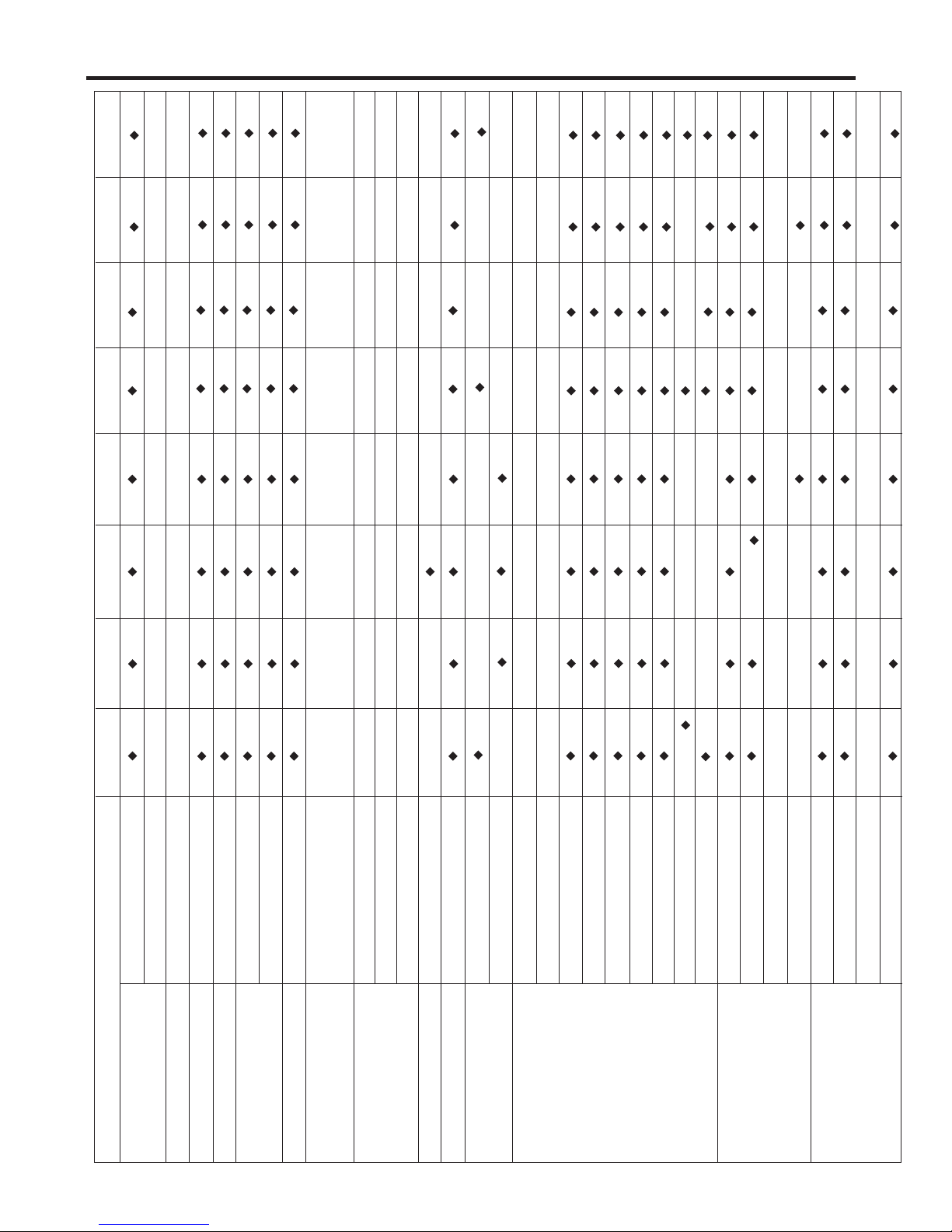
1. R ef. No: G B B530*****, G B F530*****
DIME NS IONS (mm)
TE MP E R AT UR E C ONT R OL
DE F ROS TING DE V IC E
C OMP R ES S OR
E VA P OR AT OR
R E FR IG E R ANT WE IGHT
LUB R ICAT ION OIL
C ONDE NS E R
R E FR IG E R AT OR
C OMP AR TME NT
DO OR B AS KE T
FR E E ZE R
C OMP AR TME NT
- 4 -
S P E CIFIC ATIONS
-
•
G B B539***Z*
-
G B B539***F*
•
-
539*** W*
G B F
-
G B B 539***W*
-
G B B 539***P*
-
•
•
•
•
-
•
67g (FLA102)
61g (BMG089)
180cc(FLA102)
-
170cc(BMG089)
-
•
•
2E A (option 1)
•
(option - )
•
•
(option - )
(option - )
•
•
•••
(option )
-
•
-
2E A
•
•
-
•
•
•
•
•
•
-
•
67g (FLB124)
65g (FMA102)
-
175cc(FLB124)
-
120cc(FMA102)
•
•
-
•
•
•
•
-
•
•
•
(option )
2E A
-
•
•
•
2E A
-
•
•
-
•
-
(option 1) (option 1)
-
57g (BMG089)
61g (CMA089)
-
170cc(BMG089)
•
•
-
•
•
•
•
-
•
2E A
-
•
-
• •
3E A
(option )
-
•••
-
•
•
•
•
-
-
•
•
•••••••
•
•
•
•
63g (CMA089)
57g (BMG089)
61g (CMA089)
67g (FLA102)
61g (BMG089)
-
170cc(BMG089)
180cc(FLA102)
150cc(CMA089)
170cc(BMG089)
•
150ccCMA089) 150ccCMA089)
- -
Yes(CMA089)
-
•
•
No (FLA102/BMG089)
•
-
-
•
-
-
(option 1)
-
2E A
•
-
2E A
- -
•
•
•
(option )
-
-
- -
•••
•
•
- -
3E A
-
2E A
•
-
-
•
•
•
•
-
•
•
-
67g (FLB124)
65g (FMA102)
G B B 539***F*
F an C ooling
Micom C ontrol
F ull Automatic
He ater Defros t
He ater, S heath
595(W ) X 2010(H) X 650(D)
IT EMS
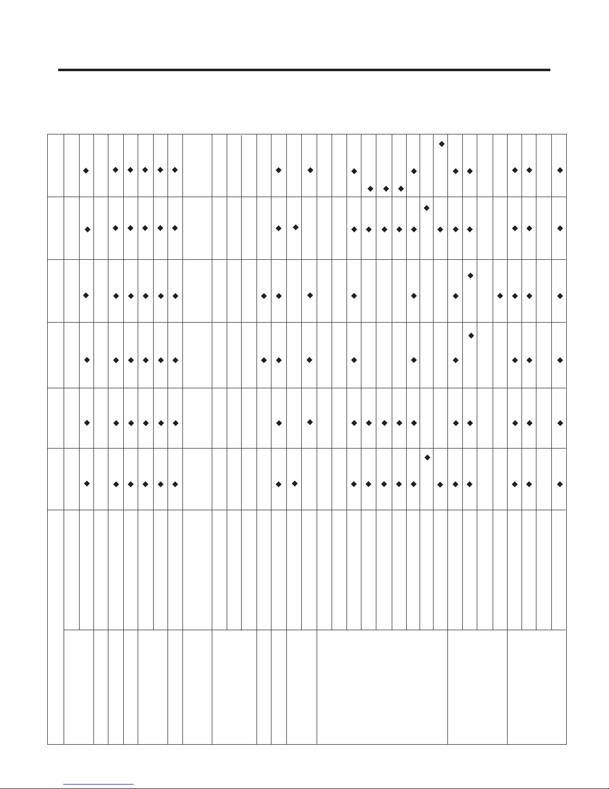
1. R ef. No: G B B539*****, G B F539*****
595(W ) X 1900(H) X 650(D)
DIME NS IONS (mm)
TE MP E R AT UR E C ONT R OL
NE T WE IGHT
C OOLING S Y S TE M
DE F ROS TING S YS TE M
R 600a
DE F ROS TING DE VIC E
R E FR IG E RAN T WE IGHT
-
175cc(FLB124)
H T S 55 MT
S 5 H FP
LUB R ICAT ION OIL
-
-
120cc(FMA102)
5HFP
P T C S tarting T ype
C OMP R ES S OR
•
•
-
-
(option 1)
2E A
•••••••••
•
•
(option )
-
•••
-
2E A
•
-
A)
(2E
P in Tube Type
S piral C ondens er
Wire C ondenser
R emovable G la s s S helf
Vita, L E D(1E A)
C over, T V (L )
C over, T V (U )
F res h 0 Zone
Magic C risper (1E A)
Vegetable Drawer (1E A)
Foldi ng S h e lf
Bottle R ack
E gg T ray
Da iry C orner
B asket
Water T ank
Tray Drawer (3E A)
Tray Ice
Ice B ox
Wire S helf
E VA P OR AT OR
C ONDE NS E R
R E FR IG E RAT OR
C OMP AR TME NT
DO OR B AS KE T
FR E E ZE R
C OMP AR TME NT
- 5 -
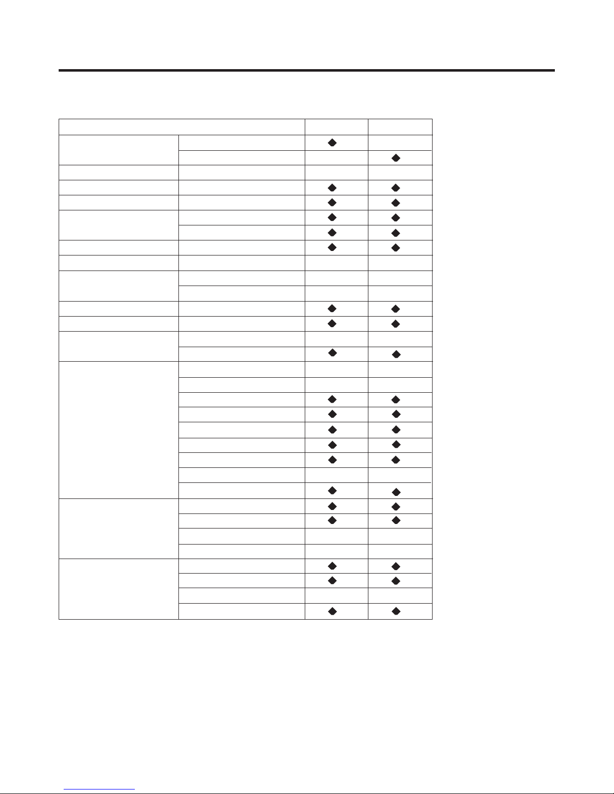
S P E C IFIC AT IONS
1. R ef. No: G B B539*****, G B F539*****
DIME NS IO NS (mm)
NE T WE IG HT
C OOLING S YS T E M
TE MP E R AT UR E C ONTR OL
DE F ROS TING S YS TE M
DE F ROS TING DE VICE
R E FR IG E R AN T WE IGHT
LUB R ICAT ION OIL
C OMP R ES S O R
E VA P OR AT OR
C ONDE NS E R
R E FR IG E R AT OR
C OMP AR TME NT
DO OR B AS KE T
F R EEZE R
C OMP AR TME NT
IT EMS
595(W ) X 2010(H) X 650(D)
595(W ) X 1900(H) X 650(D)
F an C ooling
Micom C ontrol
F ull Automatic
He ater Defros t
He ater, S heath
R 600a
5HFP
S 5 HF P
P T C S tarting T ype
P in Tube Type
S piral C ondens er
Wire C ondenser
R emovable G la ss S helf
Vita, LE D(1E A)
C over, T V (L )
C over, T V (U )
F res h 0 Zone
Magic C risper (1E A)
Vegetable Drawer (1E A)
E gg T ray
Da iry C orner
B asket
Water T ank
Tray D rawer (3E A)
Tray Ice
Ice B ox
Wire S helf (2E A)
G B B539**HW*
-
•
-
•
•
•
•
•
57g (BMG089)
61g (CMA089)
170cc(BMG089)
150cc(CMA089)
•
•
-
•
3E A
-
•
-
-
-
•
•
- -
3E A
-
•
•
-
- -
G
BB539**HP*
-
•
-
•
•
•
•
•
63g
-
•
•
•
-
•
3E A
-
•
-
-
-
•
•
3E A
-
•
•
-
GBB539**HZ*
-
•
-
•
•
•
•
•
67g
-
•
•
•
-
•
3E A
-
•
-
-
-
•
•
-
3E A
-
•
•
-
-
- 6 -
S P E C IFIC AT IONS
1. R ef. No: G B B530***M*, GB F539***M*
DIME NS IO NS (mm)
NE T WE IGHT
C OOLING S YS T E M
TE MP E R AT UR E C ONTR OL
DE F ROS TING S YS TE M
DE F ROS TING DE VICE
R E FR IG E R AN T WE IGHT
LUB R ICAT ION OIL
C OMP R ES S OR
E VA P OR AT OR
C ONDE NS E R
R E FR IG E R AT OR
C OMP AR TME NT
DO OR B AS KE T
F R E E ZE R
C OMP AR TME NT
IT EMS
595(W ) X 2010(H) X 650(D)
595(W ) X 1900(H) X 650(D)
F an C ooling
Micom C ontrol
F ull Automatic
He ater Defros t
He ater, S heath
R 600a
HTS 55M T
S 5 H FP (5CST)
P T C S tarting T ype
P in Tube Type
S piral C ondens er
Wire C ondenser
R emovable G la s s S helf
Vita, L E D(1E A)
C over, T V (L )
C over, T V (U )
F res h 0 Zone
Magic C risper (1E A)
Vegetable Drawer (1E A)
Folding Shelf
Bottel Rack
E gg T ray
Da iry C orner
B asket
Water T ank
Tray D rawer (3E A)
Tray Ice
Ice B ox
Wire S helf (2E A)
G B B530**QM*
•
-
-
•
•
•
•
•
61g
- -
170cc 170cc
•
•
-
•
3E A
-
•
• •
•
•
•
-
•
•
• •
3E A
-
•
•
-
•
G B B 539**QM*
-
•
-
•
•
•
•
•
61g
•
•
-
•
2E A
-
•
•
•
•
-
•
•
2E A
-
•
•
-
•
- 7 -
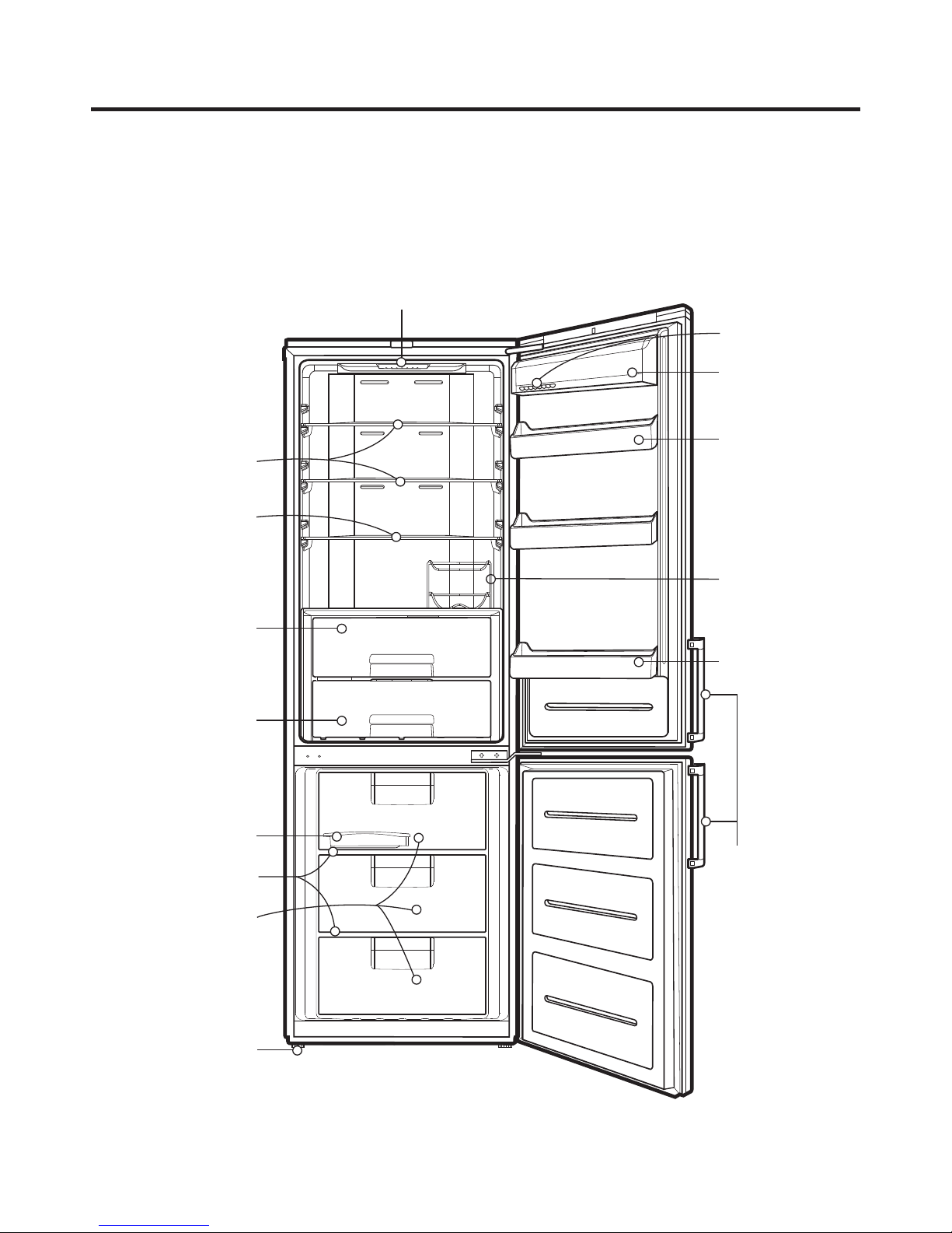
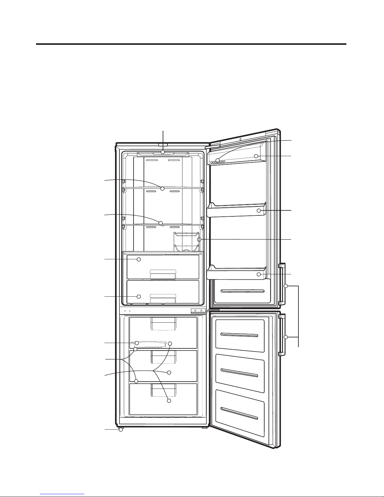
P A RTS I D E N T I F ICA T I O N
G B B530****
Model Name : GBB530**Q**, GBB530**C**
Lamp
Removable
Glass Shelf
Removable
Glass Shelf
(Folding shelf
Optional)
Egg Tray (Optional)
Dairy Corner
(Optional)
Basket Door
Bottle Rack
(Optional)
Vegetable
Drawer (Used to
keep fruits and
vegetables etc.
fresh and crisper)
Fresh '0' Zone
(Optional)
Ice Tray
Wire Shelf
Freezer
Compartment
Leveling Screw
Basket Door
EZ Open
Handle
(Optional)
- 8 -
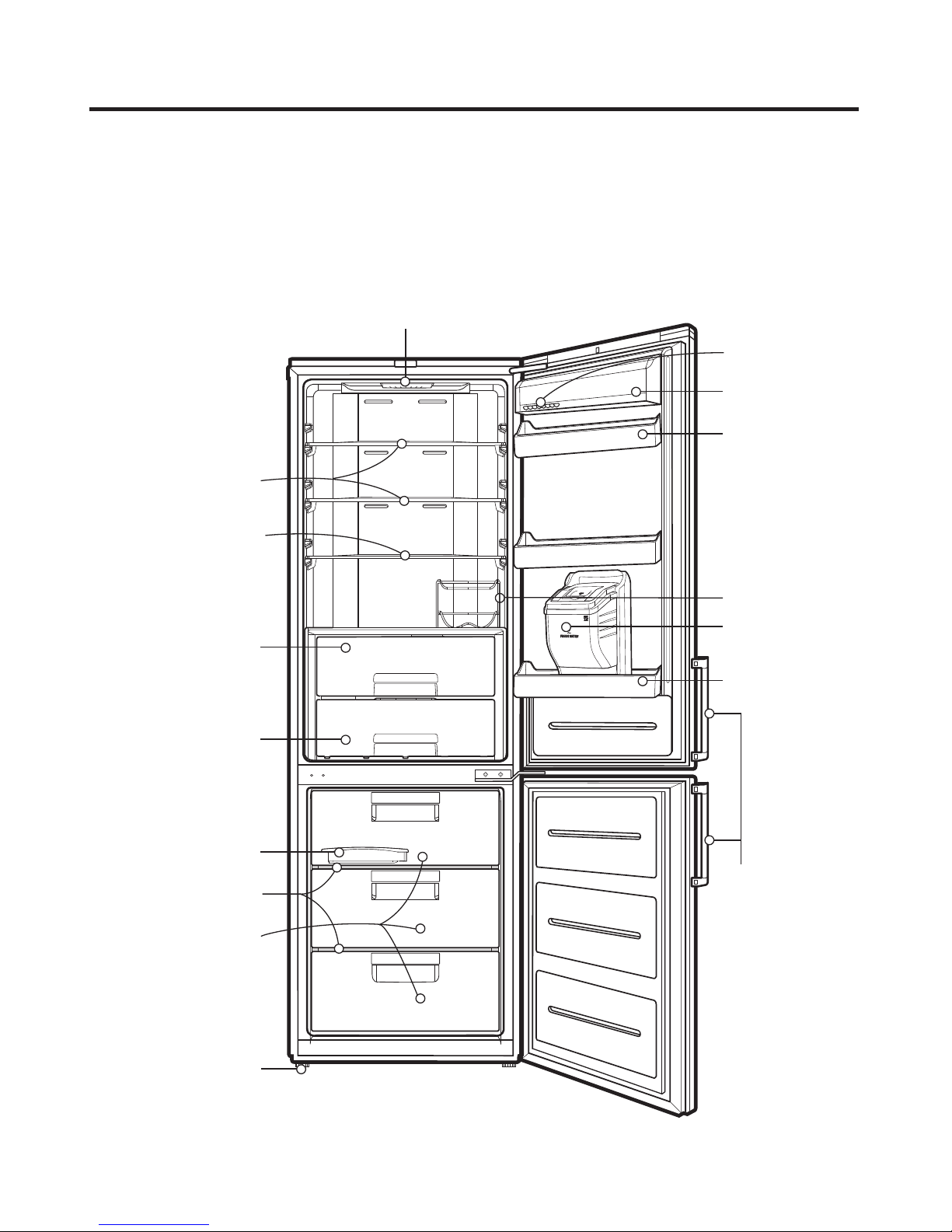
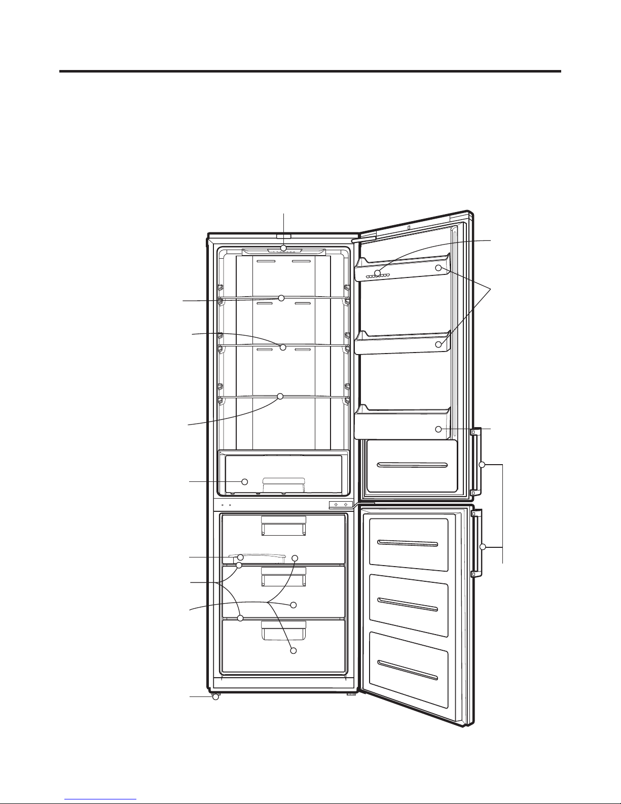
P A R T S I D E N T I F I C ATIO N
G B B530*****
Model Name : GBF530**Q**
Lamp
Removable
Glass Shelf
Removable
Glass Shelf
(Folding shelf
Optional)
Vegetable
Drawer (Used to
keep fruits and
vegetables etc.
fresh and crisper)
Fresh '0' Zone
(Optional)
Egg Tray (Optional)
Dairy Corner
(Optional)
Basket Door
Bottle Rack
(Optional)
Water Tank
(Optional)
Basket Door
Ice Tray
Wire Shelf
Freezer
Compartment
Leveling Screw
EZ Open
Handle
(Optional)
- 9 -
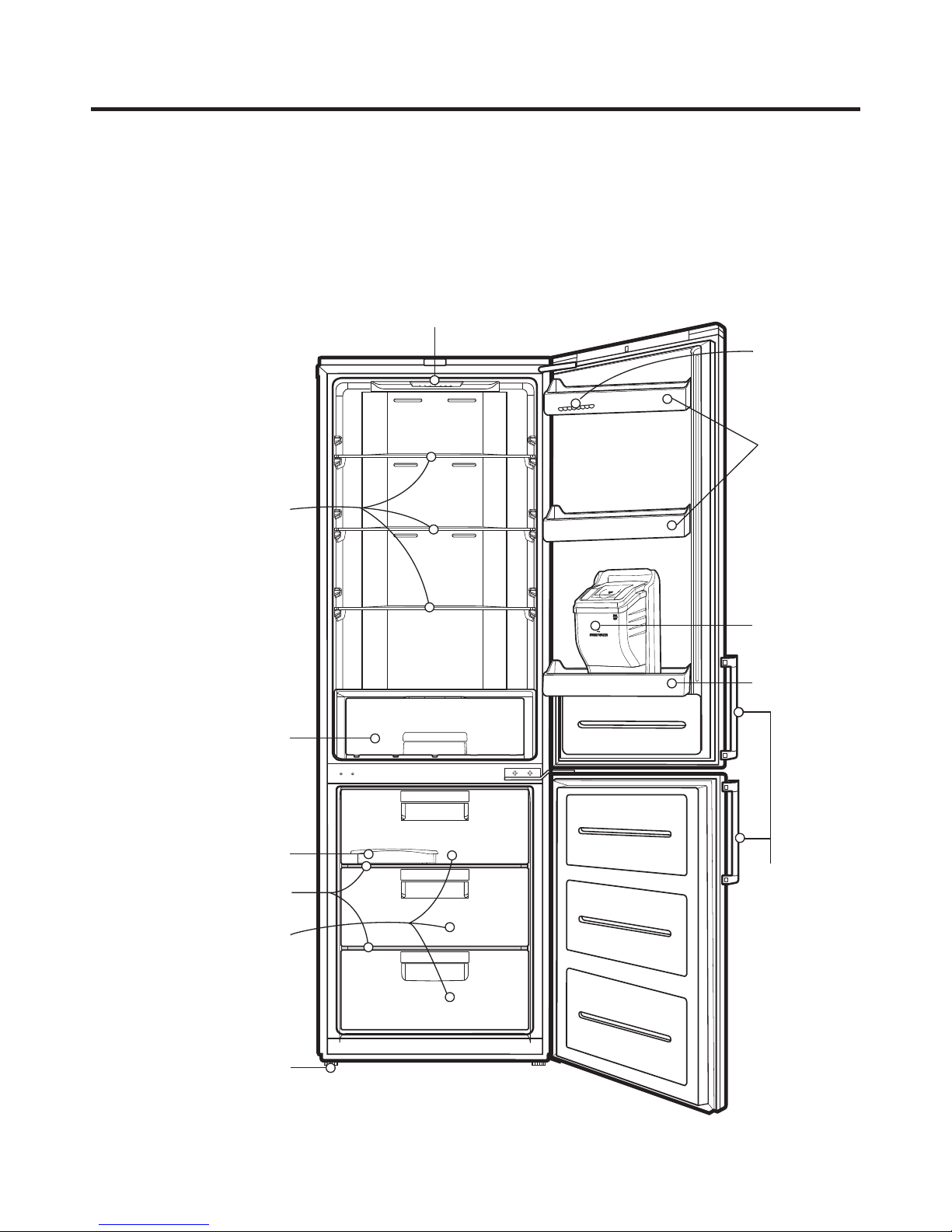
P A R T S ID E NTI F I C A T I O N
G B B539*****
Model Name : GBB539**QF*, GBB539**QP*, GBB539**CF*, GBB539**CP*, GBB539**CZ*, GBB539**QZ*
Lamp
Egg Tray (Optional)
Dairy Corner
(Optional)
Removable
Glass Shelf
Removable
Glass Shelf
(Folding shelf
Optional)
Vegetable
Drawer (Used to
keep fruits and
vegetables etc.
fresh and crisper)
Fresh '0' Zone
(Optional)
Ice Tray
Wire Shelf
Freezer
Compartment
Basket Door
Bottle Rack
(Optional)
Basket Door
EZ Open
Handle
(Optional)
Leveling Screw
- 10 -
P A R T S ID E NTI F I C A T I O N
G B B539****
Model Name : GBB539**QW*, GBB539**HW*
Lamp
Egg Tray (Optional)
Removable
Glass Shelf
Removable
Glass Shelf
(Folding shelf
Optional)
Removable
Glass Shelf
Vegetable
Drawer (Used to
keep fruits and
vegetables etc.
fresh and crisper)
Ice Tray
Wire Shelf
(Optional)
Freezer
Compartment
Basket Door
Basket Door
EZ Open
Handle
(Optional)
Leveling Screw
- 11 -
P A R T S I D E NTI F I C A TIO N
G B B539****
Model Name : GBF539***W*
Lamp
Removable
Glass Shelf
Egg Tray (Optional)
Basket Door
Vegetable
Drawer (Used to
keep fruits and
vegetables etc.
fresh and crisper)
Ice Tray
Wire Shelf
Freezer
Compartment
Leveling Screw
Water Tank
(Optional)
Basket Door
EZ Open
Handle
(Optional)
- 12 -

INS TR UC TIONS F OR R E VE R S ING DOOR S WING
This re frigera tor a llows the owner to change the door s wing if desired. T he hinging of the doors ca n be changed
to the opposite s ide anytime you wish.
When revers ing the door s wing :
R ead the instructions all the way through before starting.
·
Ha ndle pa rts carefully to avoid s cratching paint.
·
S et s crews down by their related parts to avoid using them in the wrong places .
·
P rovide a non-s cratching work surface for the doors .
IMPO R TA NT
Once you begin, do not move the ca binet until door-swing revers al is completed.
Thes e instructions are for changing the hinges from the right side to the left s ide-if you ever want to cha nge the hinges back
to the right s ide, follow thes e s ame ins tructions and re verse all reference s to left and right.
B efor R emoving the Doors , empty a nd R emove a ll the Door Bas kets of both R efrigerator/Freezer D oors , including the B ank
Da iry. C lose both door
Warning E lec tric S hoc k Hazar d
Dis connect electrical s upply to refrigera tor before installing. F ailure to do so could re s ult in death or serious injury.
s before removing hinge pins .
C a ution :
Do not let either door drop to the oor. Doing s o could dama ge the Door S top.
- 13 -
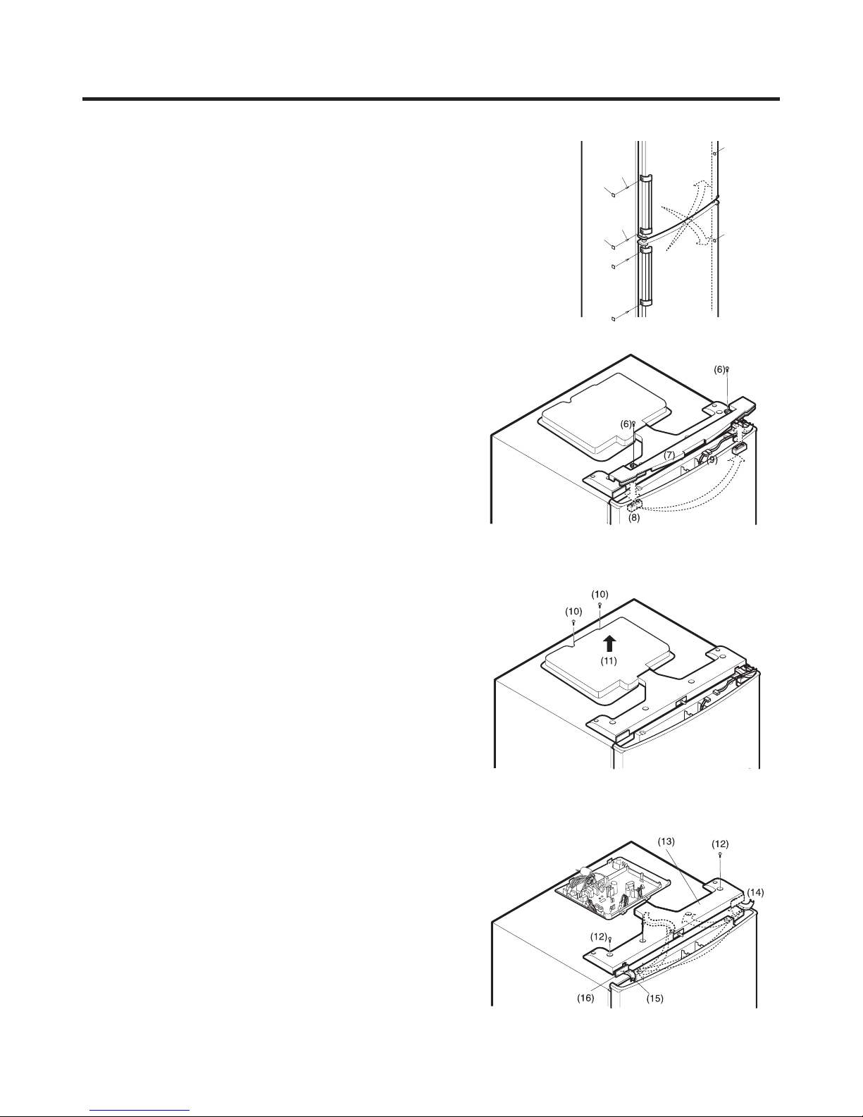
INS TR UC TIONS F OR R E VE R S ING DOOR S WING
1) R emove screws(3) after removing a C AP(2) from the s ide
of the refrigerator room HANDLE (1).
The freezer room HAND LE (5) ma y be also dis assembled in
a same may as the refrigera tor room H ANDLE (1).
2) R emove the s crews (6) in the DE CO C OVE R (7).
R emove the DE CO CO VE R (7) and move the C OV ER
HING E (8) to s ide of DE C O C OV E R (7). Disassemble the
Housing C onnector(9) ins ide of the DE CO C OV E R (7).
(2)
(2)
(4)
(3)
(1)
(3)
(4)
(5)
3) R emove the s crews (10) in the C OV E R -P W B (11), a nd
remove the C OVE R -P WB(11).
4) R emove the s crews (12) in the T OP C O V E R F R ONT (13)
and remove the TOP C OV E R F RONT (13) .
5) R emove the H OLDE R C OR D (14) placed in right a nd ins ert
it to ce nter. And then move COVE R F R ONT (16).
Take out the HOL DE R C OR D(spare) (15) and to pl
ac e in
the center of TOP C OV E R F RONT (13), and insert to the
left s ide.
- 14 -
INS TR UC TIONS F OR R E VE R S ING DOOR S WING
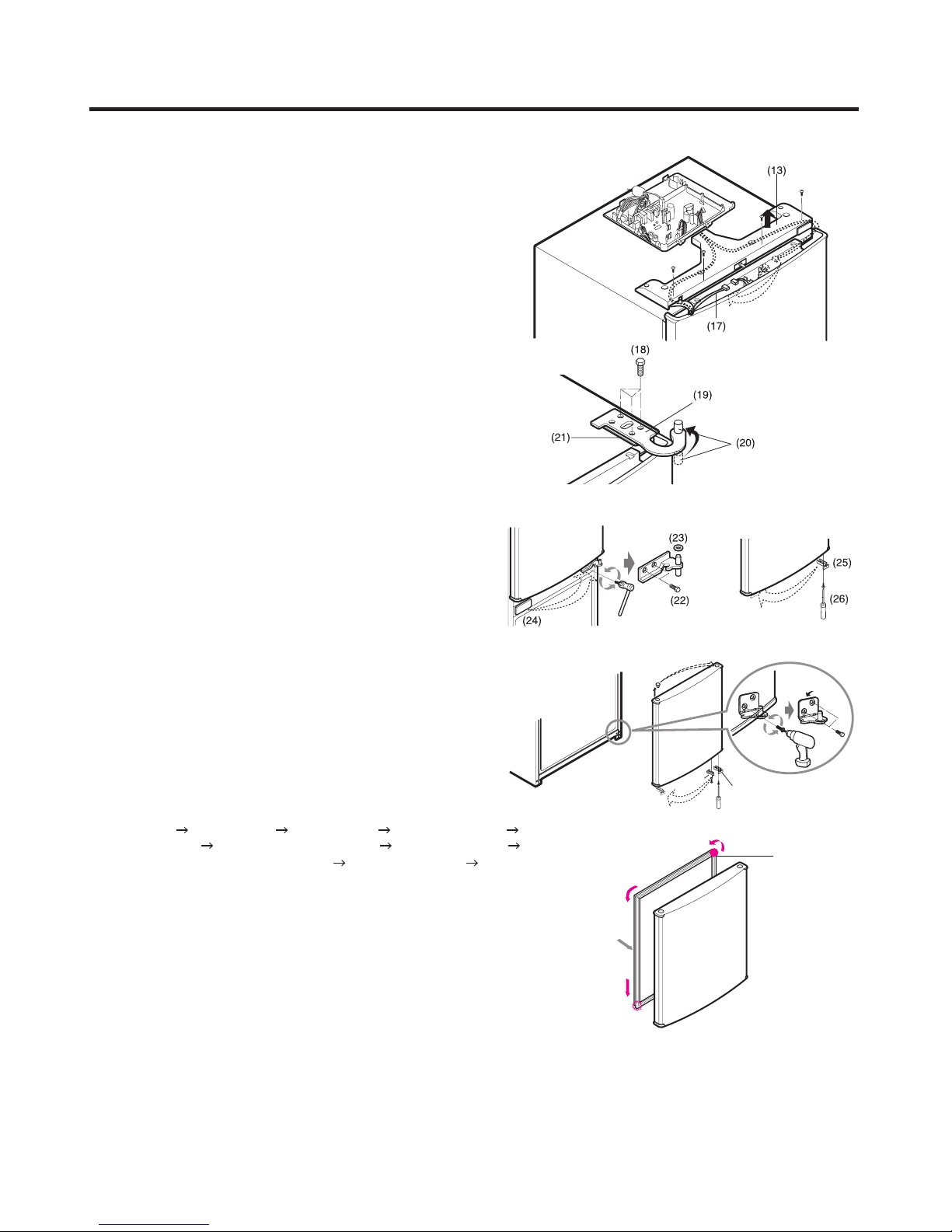
6) Take out the LEAD WIRE(17) assembly from the TOP
COVER FRONT(13) and assemble it on the left side.
7) Remove bolts(18) securing HINGE-U(19).
Uns crew of the hinge pin(20).
Place HINGE-U and seat hinge upside down and apply
them to left side of the refrigerator.
NOTE:
Seat hinge to be placed under the HINGEU(19).
8) Remove bolts(22) securing HINGEC(23) and then remove
HINGE-C(23).
Remove the freezer door. Move in left side of the
refrigerator CAP(24). Move to left side of the refrigerator
door BRACKET DOOR (25) and screw (26).
9) Remove Bolts(27), HINGE-L (28), STOPPER (29), (30) and
Lavel(31).
Use the new HINGE-L in Drawer and attach a label to a
screw Hole.
10) Assemble:
HING E -L F reezer Door HIN G E -C (23) R efrigerator Door
HING E -U(19) TO P C OV ER F R O NT(13) C OVE R P WB (11)
Connect the H ous ing C onnector(9) DE C O C OV E R (7) HAN DLE (1) (5)
11) Remove Freezer and Refrigerator Door Gaskets and turn them 180˚.
Assemble them again and put some lubricant onto their surface.
NOTE:
Reversing the doors is not covered by the warranty.
LUBRICANT
(29 )
(32 )
(27 )
(30 )
G AS KE T
- 15 -
DI S A SSEMBL Y
1. DOOR
•
Freezer Door
1) Refer to previous chapter "Instruction for Reversing
Door Swing".
2) P ull out Door Gasket to remover from the Door
Foam Assembly, F .
G AS KE T
•
Refrigerator Door
1) Refer to previous chapter "Instruction for Reversing
Door Swing".
2) Pull out the Door Gasket to remove from the Door
Foam Assembly, R .
F igur e 7
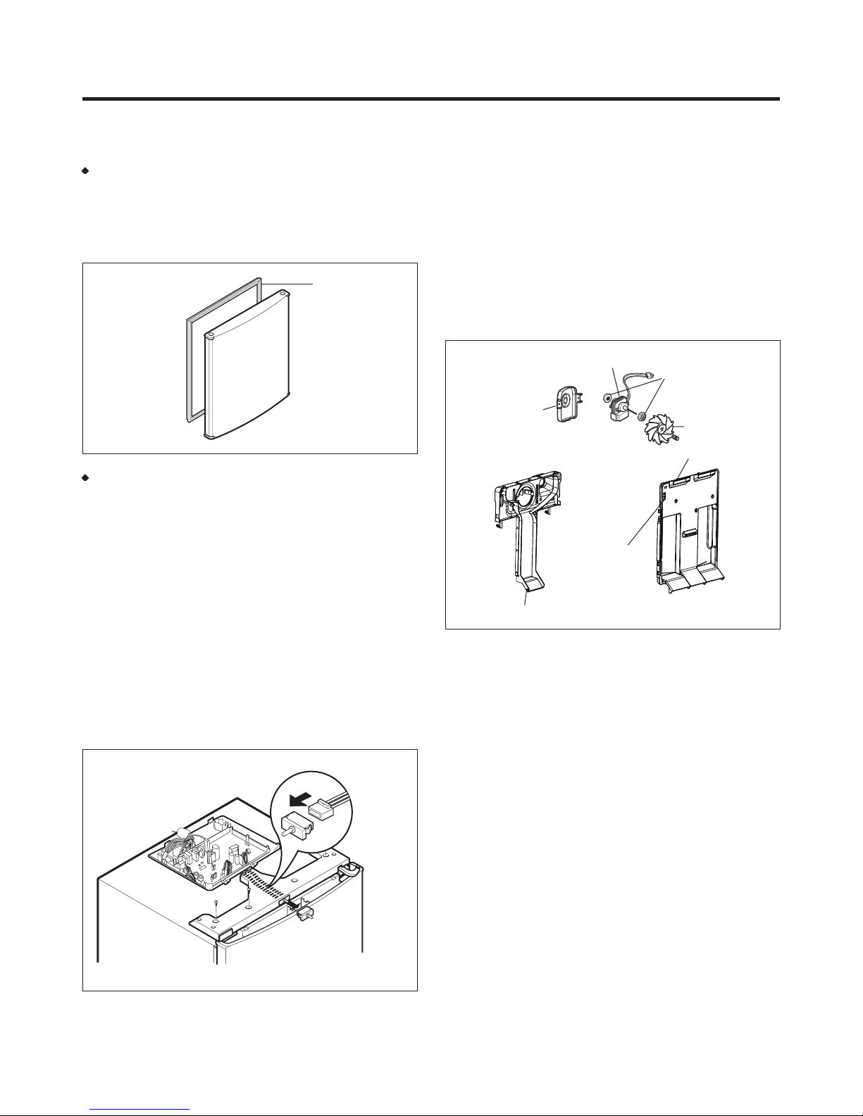
3. FAN AND FAN MOTOR
1) Remove all of the freezer compartment,
(Involved wire shelf, ice maker)
2) Pull out the Grille Fan and Shroud F.
3) Disconnect the Housing of lead wire.
4) Remove three screws in Grille Fan.
5) Separate Shroud, F to the Grille Fan.
6) Loose three screws xed to the Bracket.
7) Pull out Bracket and then remove the Fan Motor
Assembly.
* Fan Motor Assembly can’t separate.
MOTOR
BRACKET,
MOTOR
SENSOR
DAMPER
FAN
GRILLE, FAN
2. DOOR SWITCH
1) Unplug the power cord from the outlet.
2) Loosen s ix screws in upper part and disconnect Top
Cover Front.
3) Disconnect Lead Wire from switch.
4) Disengage hook behind the switch by pressing it with
hands.
F igur e 9
SHROUD
Figure 11
- 16 -
DI S A SSE M B L Y
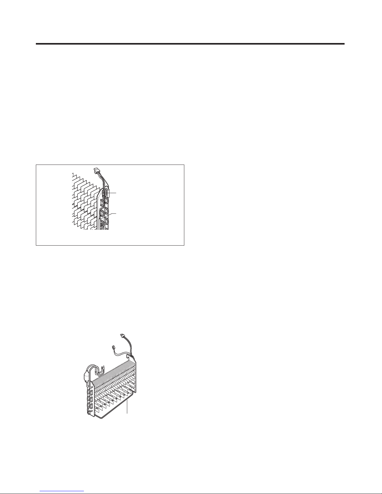
4. DE F R OS T C ONT R OL A SSE MB LY
Defrost C ontrol Assembly cons is ts of T hermistor and F use,
Melting. Thermis tor functions to defros t automatically a nd it
is a ttached to metal side of the E vapora tor and s enses
tempera ture.
F us e, Melting is a kind of s afety device for preventing
overheating of the Hea ter when defros ting.
At the temperature of 77˚C, it s tops the emission of heat
from the Hea ter.
1) P ull out the S hroud, F after removing the G rille .
- Freezer
P ull out the G rille. - Fridge
arate the connector connec ted with the D efrost
2) S ep
C ontrol Assembly a nd replace new one .
Thermistor
F us e, Melting
F igur e 12
5. FR EEZE R HE AT E R , S HE AT H
In this refrigerator, H eater, S heath is us ed for defros ting
hea ter. D uring heating, the temperature of heater rise s
about 300~350˚C . T herefore, be careful not to burn while
servicing.
1) After removing the G rille and S hroud, s epara te the
He ater, S hea th by disconnecting the conne ctors.
2) E xcha nged Hea ter, S heath and connected the hous ing.
He ater, S hea th
F igur e 13
- 17 -
ADJUSTMENT
1. COMPRESSOR (In A++ and A+ Models)
1) Role
The compres s or intakes low tempera ture and low pressure
gas evapora ted from E vaporator of the R efrigerator, and
condenses this gas to high tempera ture and high pres s ure
gas , and then plays delivering role to C ondenser.
2) Composition
The C ompressor is C ompose d of C ompres s or Apparatus
compressing ga s , C ompres sor Motor moving C ompressor
Apparatus and C as e protecting C ompre s s or Apparatus
and Motor. T here is R elay Ass embly (one set of
P T CS tarter and O ver L oad Protector (OLP )) in
C ompre s s or. O n the other ha nd, becaus e the C ompre s s or
cons ists of 1/1000mm processing precis ion components
and is sealed after production in abs ence of dust or
humidity, dea l and repair w
ith ca re.
3) Note for Usage
(1) Be ca reful not to a llow over-voltage a nd over-current.
(2) No S trike
If applying forcible power or strike (dropping or care les s
dea ling), poor ope ration and nois e may occur.
(3) Us e proper e lectric components appropriate to the
C ompre s s or.
(4) Note to K eep C ompre s s or.
If C ompressor gets wet in the rain and rus t in the pin of
He rmetic T erminal, the res ult may be poor operat
and poor contac t may caus e.
ssor ins ide in replacing the
C ompre s s
noise.
ion
2. PTC-STARTER (In A++ and A+ Models)
1) Composition of PTC-Starter
semiconductor s ta rting device which us es cera mic
material and this material cons ists of B aTiO
(2) The higher the temperature is , the higher becomes the
res istance value. Thes e features are used as s tarting
device for the Motor.
2) Role of PTC-Starter
(1) PT C is a ttached to Hermetic C ompres s or used for
R efrigera tor, S how C as e a nd starts Motor.
(2) C ompres sor for household refrigerator applies to
single-phase induction Motor.
F or normal operation of the single-phase induction
and s ub-coil. After the starting is over, the current in
the a bove roles . S o, PT C is us ed a s a motor s tarting
device.
3.
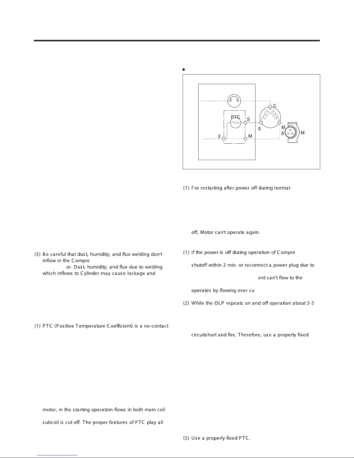
3) PTC-Applied Circuit Diagram
•
According to S ta rting Method for the Motor
OV E R LOA D
P ROT E CT OR (O .L.P )
C OMP R E SS O R
MOTOR
P TC S TAR TE R
R S IR
R E LAY AS SE MBL Y
HE R ME TIC
TE R MINAL
Figure 9
4) Motor Restarting and PTC Cooling
C ompre s s or Motor operation, plug the power cord after
5 min. for pres s ure ba lance of R efrigera ting C ycle a nd
P T C cooling.
(2) During normal opera tion of the C ompres sor Motor, P TC
elements genera te heat continuously. T herefore, if P TC
isn't cooled for a while after the power has been s hut
5) Relation of PTC-Starter and OLP
ssor a nd
the power is on before the P TC is cooled, (instant
misconnecting), the P TC is n't cooled a nd a res istance
value grows. As a res ult, curr
subcoil and the Motor can't operate a nd the O LP
rrent in only in the
main-coil.
times, P TC is cooled a nd C ompres sor Motor performs
normal operation.
If OLP doesn't opera te when P T C is not cooled,
C ompre s s or Motor is worn a way and ca us es
OLP without fail.
6) Note to Use PTC-Starter
(1) Be ca reful not to a llow over-voltage a nd over-current.
(2) No S trike
Don't apply a forcible power or s trike .
(3) Keep a part from a ny liquid.
If liquid such as oil or water away enter the P TC , P TC
materials it may break due to insulation breakdown of
the ma terial its elf.
(4) Don't change P T C at your convenience.
Don't disa s s emble PT C and mold. If the exterior to the
P T C-starter is damaged, res istance value is a ltered
and it may caus e poor starting of the compres sor mo
may cause.
tor
- 18 -
ADJUSTMENT
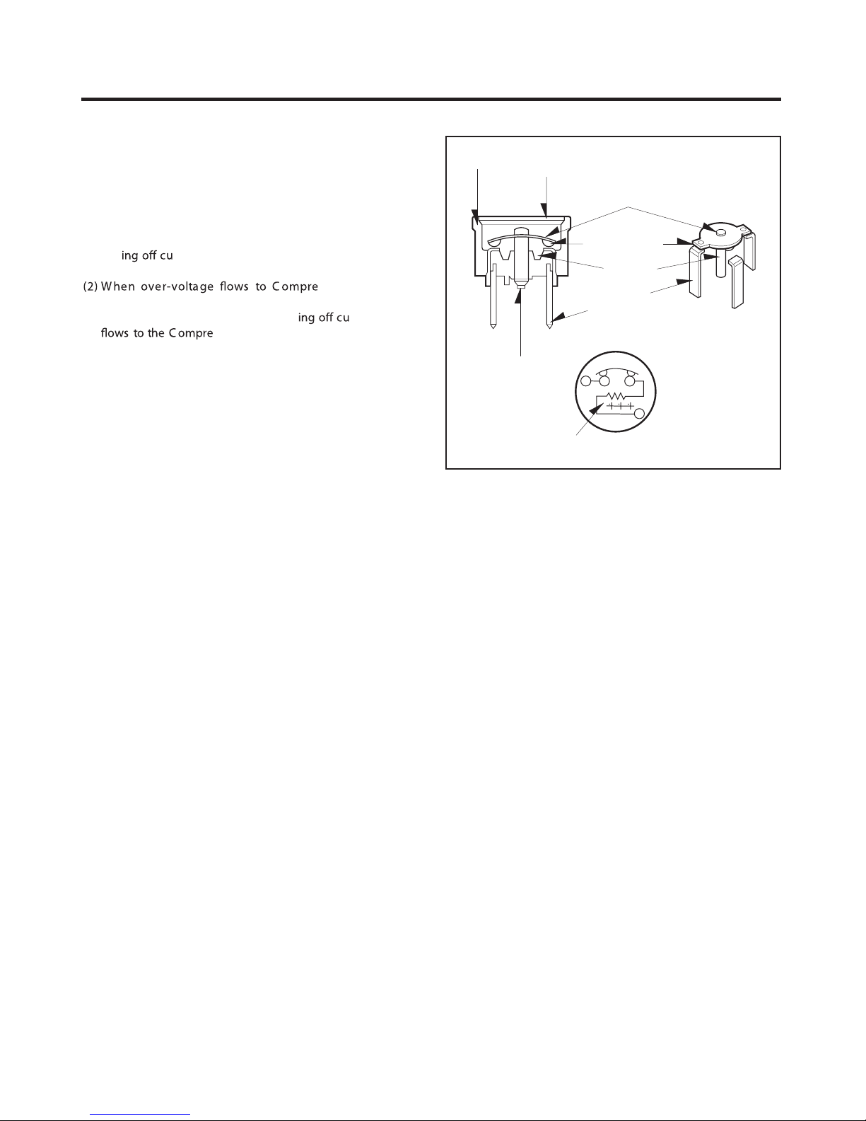
3. OLP (OVER LOAD PROTECTOR)
(In A++ and A+ Models)
1) Denition of OLP
(1) O LP (OVE R LO AD P R OT E CTOR ) is atta ched to the
H e rme tic C ompre s s or a nd prote c ts the Mo tor by
cutt
rising temperature by B imetal in the O LP .
B imetal works by hea ting the heater inside the OL P,
and the OLP prote cts Motor by cutt
2) Role of the OLP
(1) T he OL P is attached to the Hermetic C ompres sor used
for the R efrigerator and S how Ca se and prevents the
Motor C oil from being started in the C ompres sor.
(2) Do not turn the Adjus t S crew of the O LP in any way for
normal operation of the OL P.
(C omposition and connection Dia gram of OLP)
rrent in C ompres s or Motor in ca se of over-
s s or motor, the
rrent which
ssor Motor.
C ONT AC TING
P OINT
ADJ US T
S CR E W
C OV E R
HE ATE R
B IME T AL
C ONT AC TING
P OINT
HE ATE R
TE R MINALS
B IME T AL
Figure 20
- 19 -
COMPRESSOR
1. Inverter Linear Compressor
Check for defect of the inverter linear compressor in following orders:
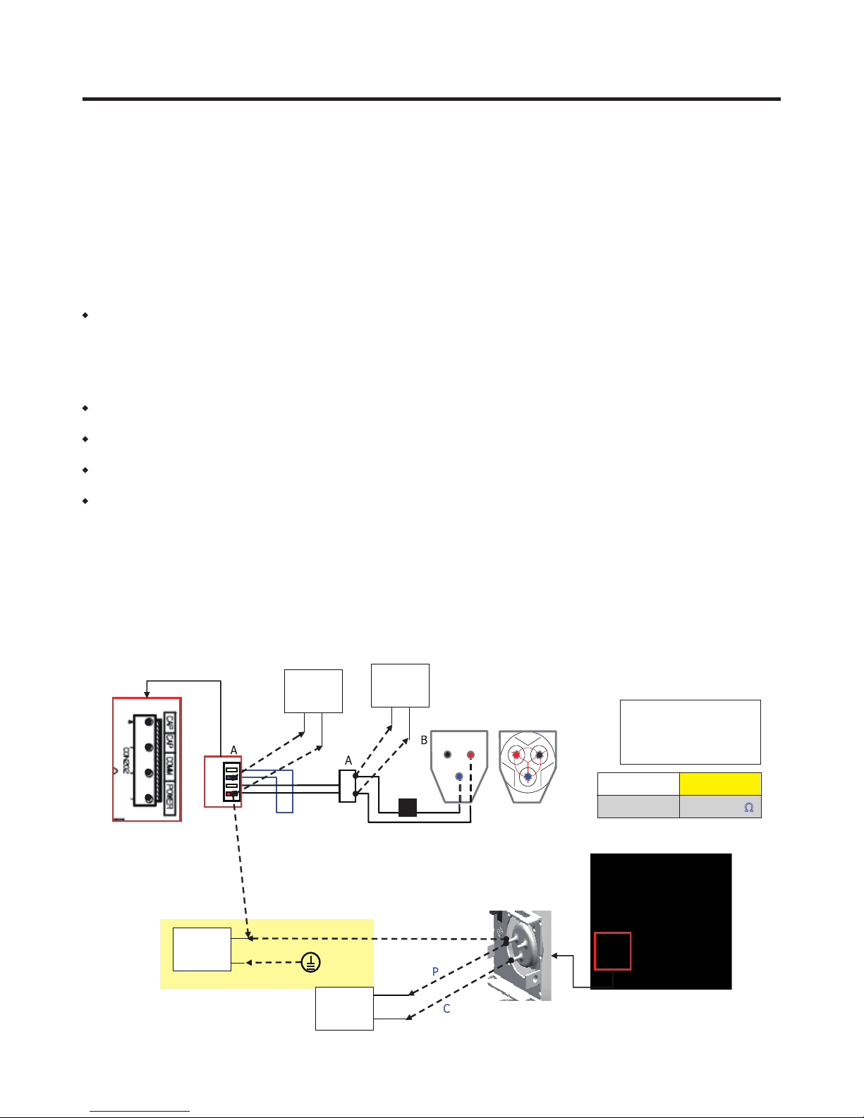
1) Method to Measure Compressor Winding Resistance
Normal Determination Criteria.
The compressor winding resistance can be determined as normal if resistance values show the values as described in
below gure when measuring resistance values of the harness (connected with compressor) to connect.
Connect201(CON201) of the main PWB as shown in below gure.
Defect Determination Criteria
•
Check connection status of the Compressor Connection Harness-P(Lead Wire) which is located at the M/C room where
resistance values measured at the CON201 Housing are shown as innite or several hundred MΩ . Separate connecting
wires of the M/C room (A-point in Figure) and then measure resistance values at the connecting wires again. The
compressor can be determined as normal if resistance values are shown as standard resistance value. Check connection
status of a harness.
Defect at M/C room connection contact or CON201 Housing contact, short-circuit of harness)
•
Where resistance values measured at A-point are also shown as innite or several hundred MΩ , disassemble a cover PTC
of the compressor terminal and check the terminal connecting status at the B-point in Figure.
•
Where there is no failure in the wiring status and resistance values are shown as innite or several hundred MΩ , it may be
determined as defect of compressor.
•
Since if there is no failure in resistance values of the compressor, it may be defective Main PWB, replace the Main PCB
and check for normal operation of the compressor.
•
When determining any defect through resistance measuring, it can be determined as normal if resistance values show as
descried in the below gure by measuring ① power and ③ common terminal or ② full power and ③ common terminal.
However, resistance values are measured when measuring ① power and ② full but measuring is meaningless since they
cannot become criteria for determining defect (measuring not required).
Caution
1. Be sure to powering o the refrigerator and measure after several minutes has passed.
2. If not accurately measuring resistance, wrong determination may be guided. (Dierence of resistance value of several W
or so may occur.)
CON201
Multi
Tester
Multi
Tester
Earth
Multi
Tester
OLP
Po N/C
Co
Because of ambient temperature or operating situations;
the values shown can have a slight devlation.
Po : Power
Co : Common
N/C : Open terminal
FLA102NAMA
Resistance
10 ~ 12
Ω
Dead Short Check
Multi
Tester
Hermetic terminal
- 20 -
COMPRESSOR
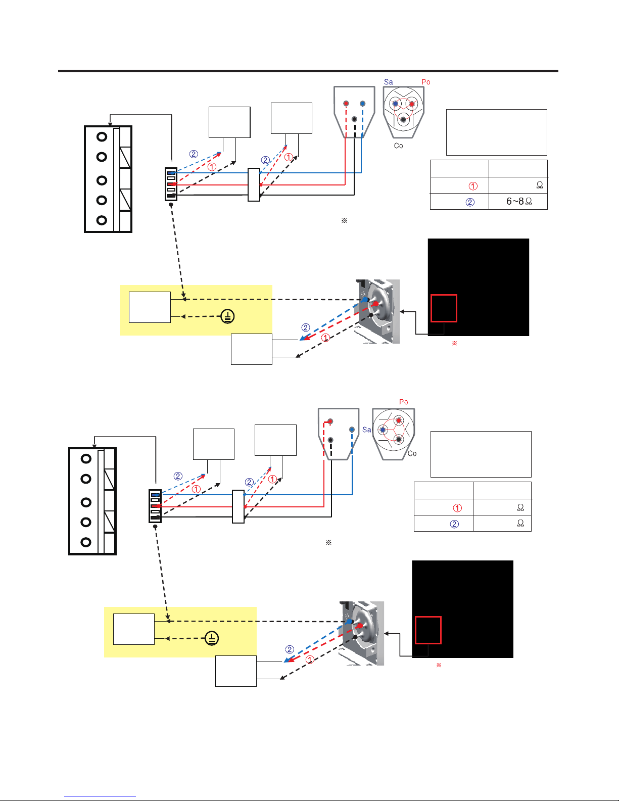
Point D
Power SaveComon
Point A
Multi
Tester
Dead Short Check
Multi
Tester
Earth
Point B
Multi
Tester
Multi
Tester
Sa : Save
Po : Power
Co : Comon
Mode
Power (
Save (
Because of ambient temperature or operating situations;
the values shown can have a slight devlation.
Hermetic terminal
)
)
FLB124NAMA
Point D
Resistance
10.5~12.5
Power SaveComon
Point A
Multi
Tester
Dead Short Check
Multi
Tester
Earth
Point B
Multi
Tester
Multi
Tester
Sa : Save
Po : Power
Co : Comon
)
)
Resistance
16.2~18.6
11.6~15.1
Mode
Power (
Save (
Because of ambient temperature or operating situations;
the values shown can have a slight devlation.
Hermetic terminal
FMA102NAMA
- 21 -
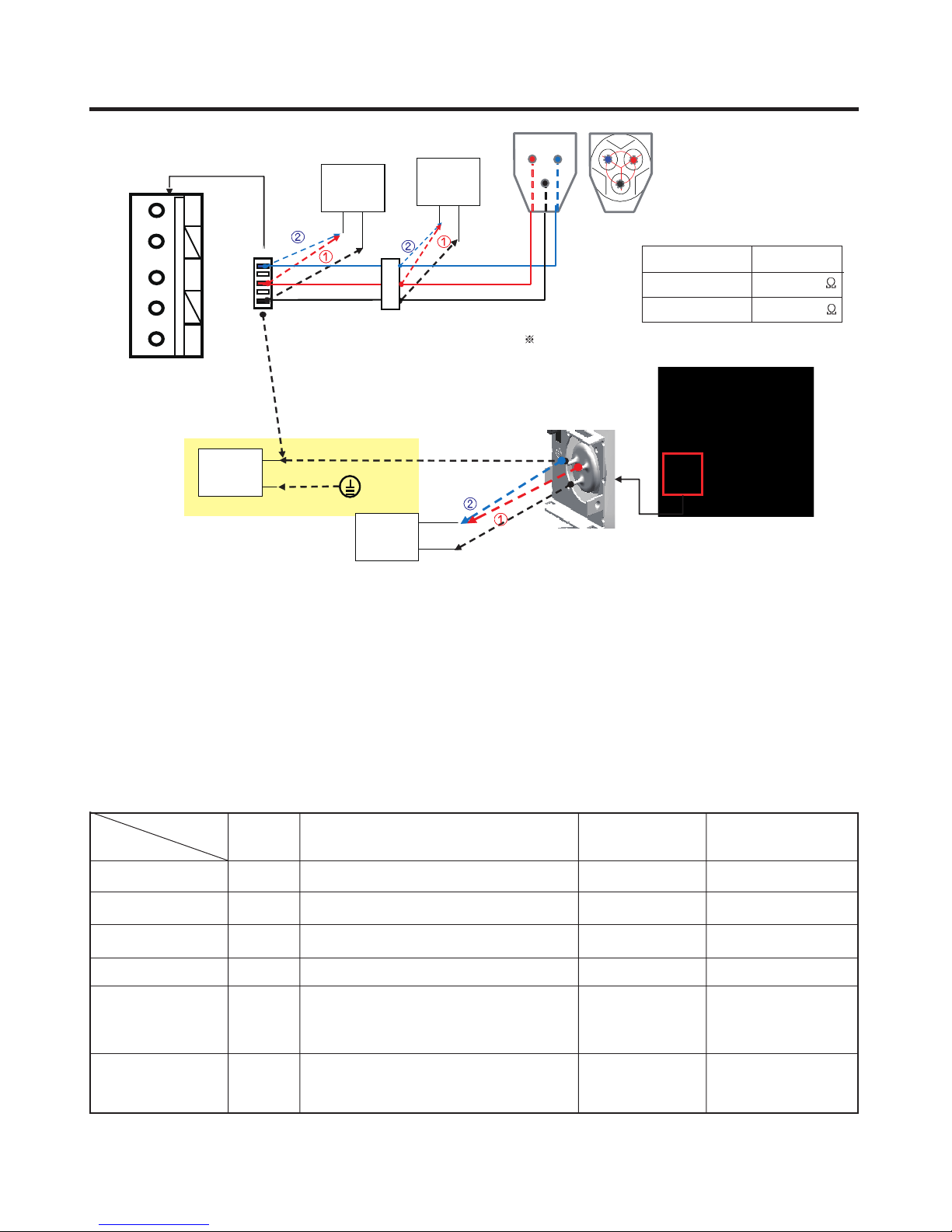
COMPRESSOR
Point D V U
Multi
Tester
W
Mode
BMG089NAMV
BMG089NHMV
Because of ambient temperature or operating situations;
the values shown can have a slight devlation.
Hermetic terminal
Resistance
12.3~15.1
12.6~15.4
Power SaveComon
Point A
Multi
Tester
Dead Short Check
Multi
Tester
Point B
Earth
Multi
Tester
2) Method to Determine Defect of Inverter Linear Drive
Determination of Comp Operation
Separate the back cover at the rear of refrigerator and determine for possible operation while touching the compressor with
the hands with insulation gloves worn.
Comp Operation
- Determine possible trip by checking operation status if cold air comes out after opening the doors of the R-Room.
Protective Logic (Trip)
- To protect the compressor from abnormal operation, this logic is used to temporally stop the refrigerator when abnormal
operation occurs and to re-operate it after abnormal signal disappears.
Compressor protection Logic Table
App.
FCT0 Trip
Stroke Trip
Locked Piston Trip
Current Trip
IPM Fault
Communication
Error
* If LED of PCB is blinking, Refer to next page.
A-Inv.
A-Inv.
A-Inv.
A-Inv.
A-Inv.
A-Inv.
Initial, Motor sensing Voltage > 2.5V+20%
Piston overruns the designed range.
Piston is locked.
Current overruns the designed range
IPM pin 14 output voltage = low (IPM Short,
High current input, or low voltage input)
Checksum error
Requirement Waiting Time
30”
1’00”
2’30”
6’00”
20”
-
- 22 -
The number of LED
blinking
1
2
5
6
7
8

COMPRESSOR
3) LED blinks one time, then repeats (FCTO Trip)
Blink BlinkOFF OFF
• FCT0 : When same trip occurs after power reset, change PCB.
Because it is occurred by overvoltage (more than 2.5V) at voltage and
current sensing parts, PCB has to be changed.
- 23 -
COMPRESSOR
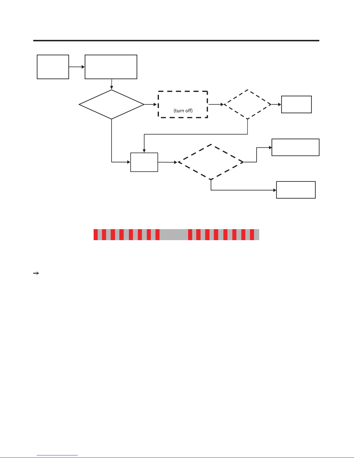
4) LED blinks two times, then repeats (Stroke Trip)
Blink BlinkBlink Blink
Purpose: Prevent abnormally long piston strokes.
Case 1. If compressor doesn’t work and LED blinks
- Cause: Possibly harness from compressor to PCB might be defective.
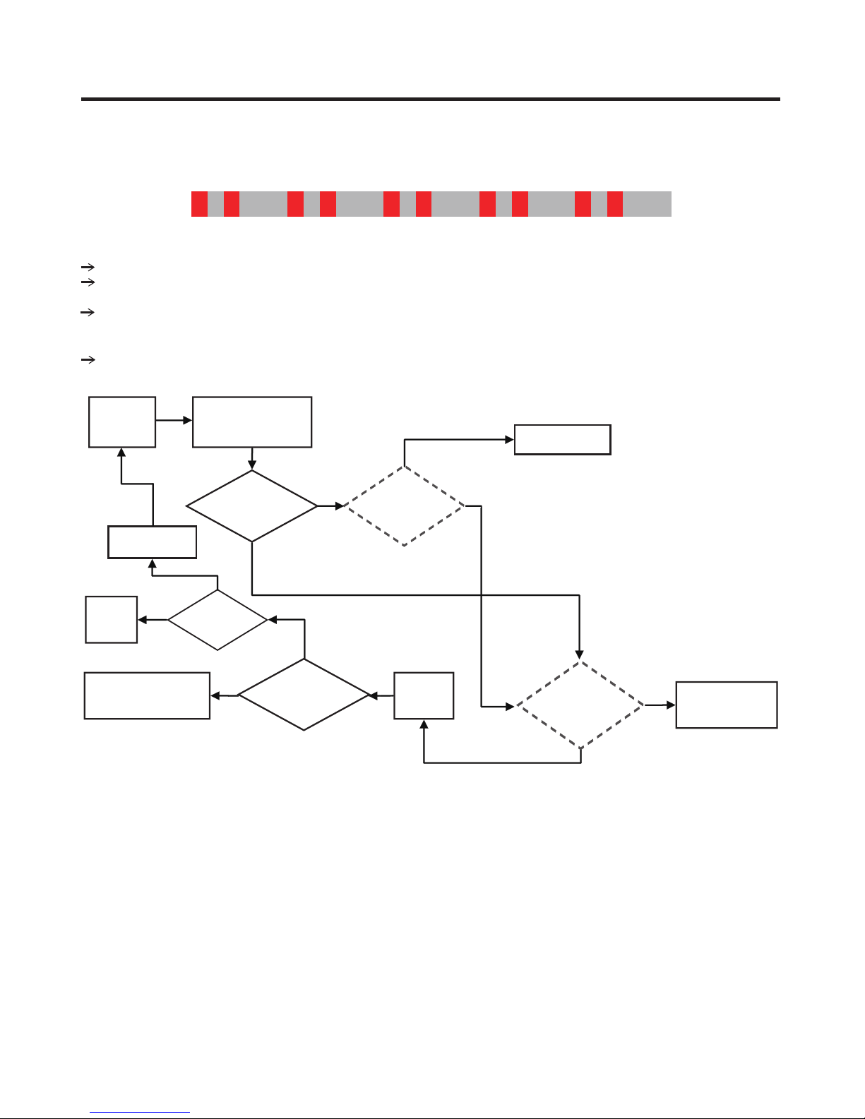
Case 2. If compressor works intermittently and LED blinks
- Cause: Condenser Fan or Freezer Fan is not running. Sealed system problem such as moisture restriction, restriction at
capillary tube or refrigerant leak.
Logic: Compressor is forced to o and then tries to restart after 1 minute.
Protection
logic
Check B
Replace
Driver PCB
Fix
Cycle
OK
NG
Blink 2 times
(Stroke Trip)
Check B2
Compressor
Doesn ’ t work
Cycle
Check E
N
Y
FFO FFOFFO
N
Y
Harness
Connecting
Check C
Y
Fix Harness
Repeat
Check Procedure
N
Stroke Trip
Occur?
Reset
Power
- 24 -
Compressor
Damage
Check C
Y
N
Replace
Compressor
COMPRESSOR
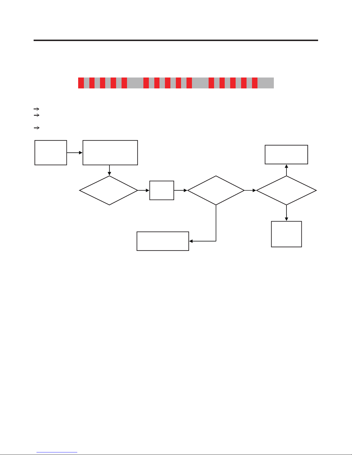
5) LED blinks ve times, then repeats (Locked Piston)
Blink Blink Blink Blink Blink OFF
Purpose: To detect locked piston
Cause: Lack of oil to the cylinder, cylinder or piston damaged and or restricted discharge.
A Locked Piston can also be caused by foreign materials inside the compressor.
Logic: Compressor is forced o and tries to restart within 2.5 minutes.
Protection
logic
Check B
Blink 5 times
(Lock Piston Trip)
Check B3
Compressor
Doesn’t work
Reset
Power
Repeat
Check Procedure
Compressor
Doesn’t work
N
Replace
Compressor
N
Y
Hi side
restriction
Y
Sealed
system
Repair
- 25 -
COMPRESSOR
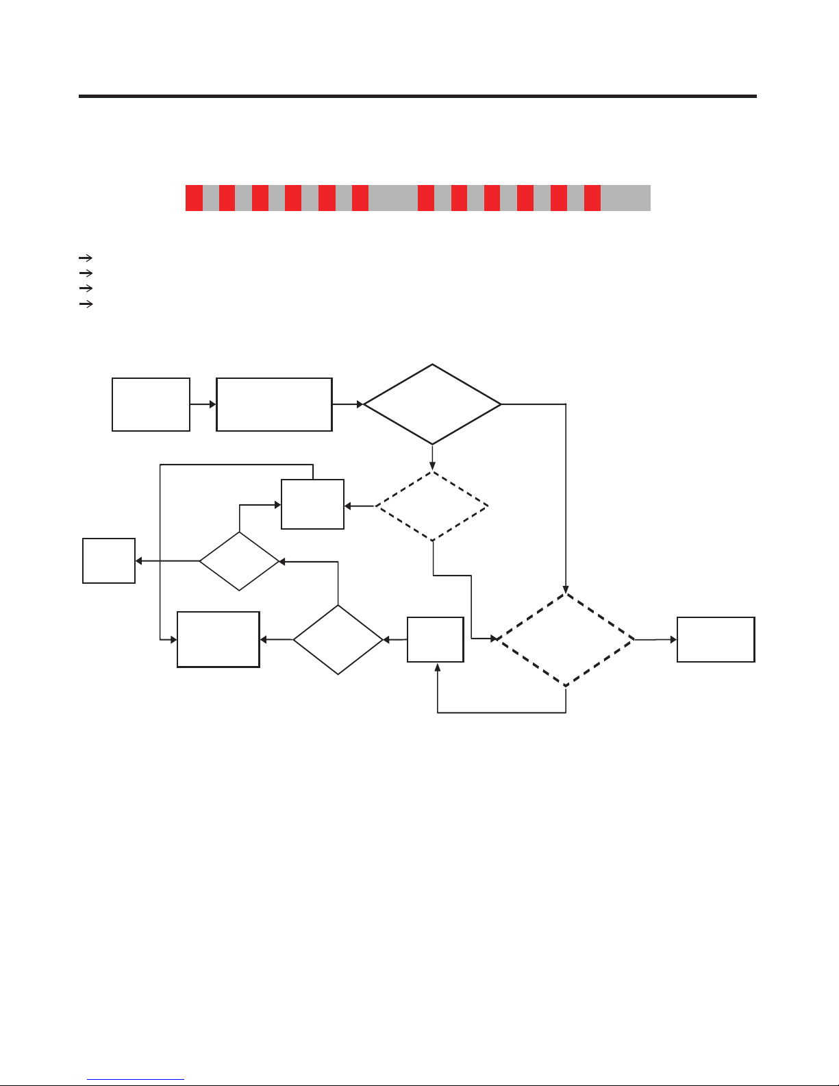
6) LED blinks six times, then repeats (Current Trip)
Blink Blink Blink Blink Blink Blink
Purpose: Prevent over-current (overload protect)
Cause: Ambient temperature is high (over 43˚C) and/or refrigerator’s condenser air movement is restricted.
Condenser Fan is stopped, restricted discharge line, compressor is damaged, or IPM device is defective.
Logic: Compressor is forced o and tries to restart after 6 min.
Protection
logic
Check B
Fix
Cycle
Blink 6 time
(Current Trip)
Check B4
Y
Cycle
Check E
Replace
Driver
PCB
Y
NG
OFF
Compressor
Intermittently
works
IPM
Check B5
Y
N
Y
Repeat
Check
Procedure
N
Current trip
Occur?
Reset
Power
Compressor
Damage
Check C3
Y
NG
Replace
Compressor
- 26 -
COMPRESSOR
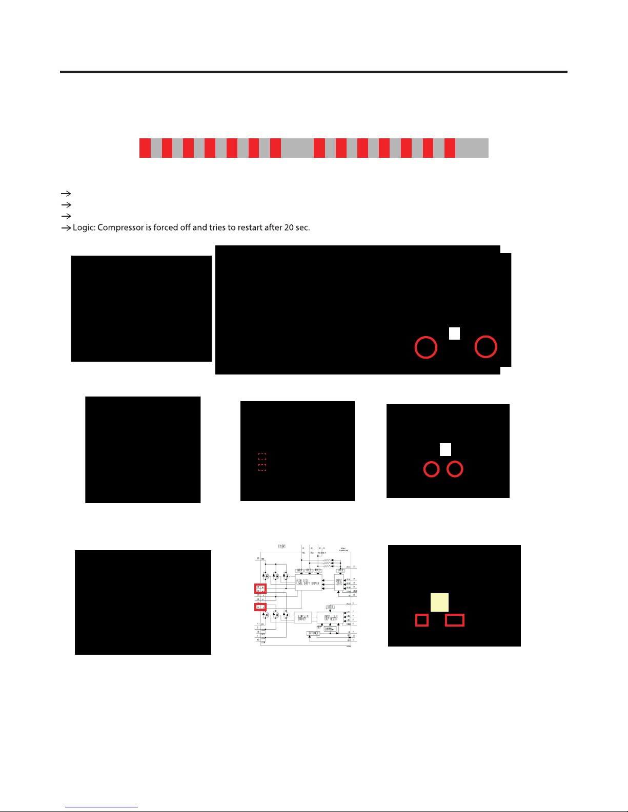
7) LED blinks seven times, then repeats (IPM Fault)
Purpose: Prevent high current due to IPM Short
Cause: Damaged IPM (Dead Short)
Test for a dead short at Point A with a VOM.
230 V
OFFBlink Blink Blink Blink Blink Blink Blink
A
100 V EBR789107
230V EBR805254
A
A
- 27 -
COMPRESSOR
Protection
logic
Check B
Blink 7 times
(Lock Piston Trip)
Check B5
Compressor
Doesn’t work
N
Power
Reset
Y
Check IPM
visual inspection
8) LED blinks eight times, then repeats (Communication Error)
Blink
Blink
Blink
Blink
Compressor
Damage
Check C3
NG
Short
Test
Point A
Y
Y
N
Replace
Drive PCB
Repeat
Check Procedure
Replace
Compressor
Blink
• Communication Error : When same trip occurs after power reset,
change PCB.
Because Program is not matching in MICOM, program has to be
rewritten or PCB has to be changed.
Blink
Blink OFF
Blink
- 28 -
 Loading...