


ARNU243BHA4
LG ARNU243BHA4, ARNU073BHA4, ARNU073M2A4, ARNU093M2A4, ARNU153M2A4 Engineering Manual
...
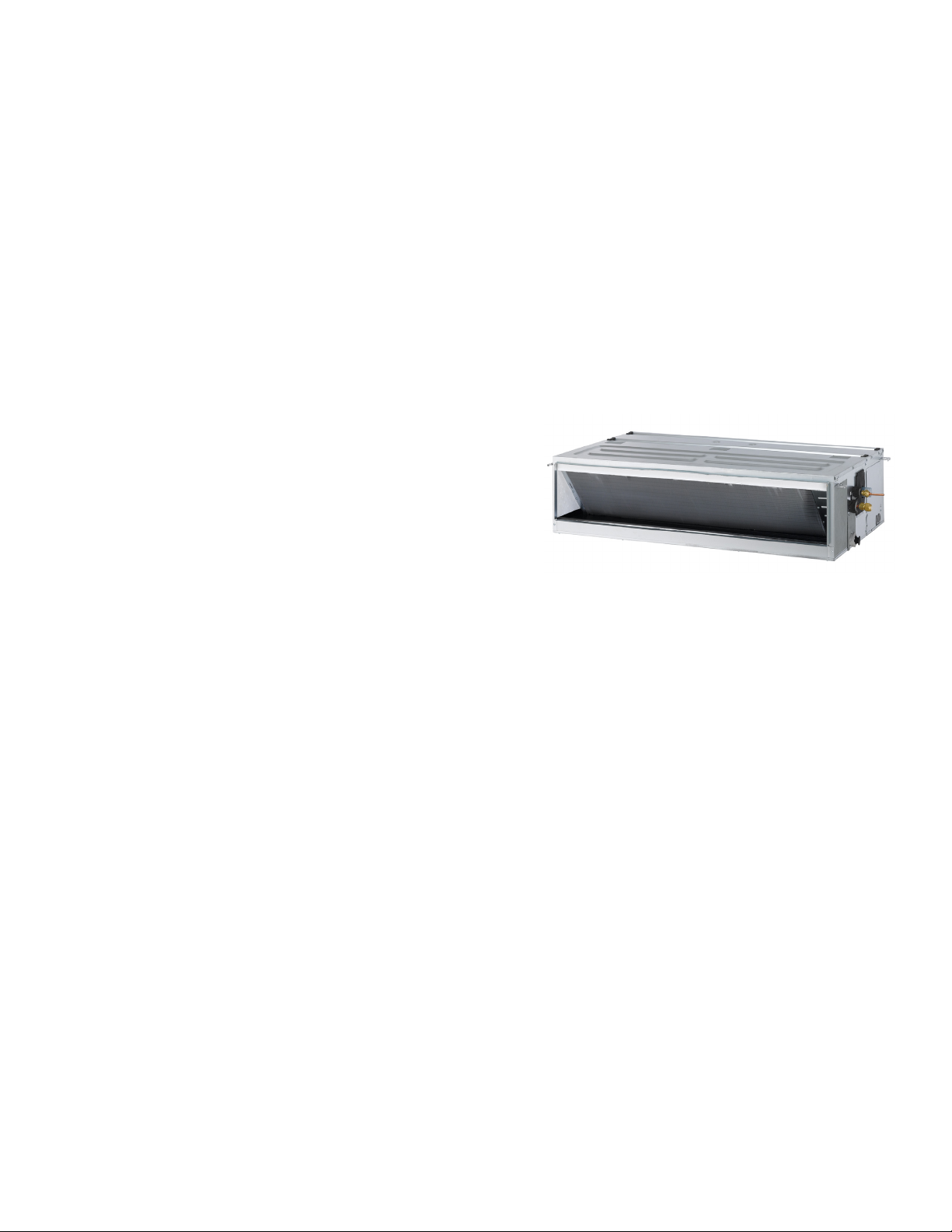
DUCTED INDOOR UNIT
ENGINEERING MANUAL
High Static Ducted
7,500 to 95,900 Btu/h
Low Static Ducted
7,500 to 24,000 Btu/h
Vertical / Horizontal Air Handler
12,000 to 54,000 Btu/h

PROPRIETARY DATA NOTICE
This document, as well as all reports, illustrations, data, information,
and other materials are the property of LG Electronics U.S.A., Inc., and are
disclosed by LG Electronics U.S.A., Inc. only in confidence.
This document is for design purposes only.
A summary list of safety precautions is on page 3.
For more technical materials such as submittals, catalogs, installation,
owner’s, and service manuals, visit www.lghvac.com.
For continual product development, LG Electronics U.S.A., Inc. reserves the right to change specifications without notice.
© LG Electronics U.S.A., Inc.

TABLE OF CONTENTS
DANGER
CAUTION
Unit Nomenclature ................................................................................. 4
LATS Overview ...................................................................................5-6
Refrigerant Charge Worksheet .......................................................... 7-9
High Static Ducted Indoor Units ................................................. 10-124
Mechanical Specications ..................................................................11
General Data ................................................................................ 12-16
Electrical Data ................................................................................... 17
External Dimensions ..................................................................... 18-21
Electrical Wiring Diagrams ........................................................... 22-29
Refrigerant Flow Diagrams ........................................................... 30-31
External Static Pressure and Air Flow ..........................................32-37
External Static Pressure Ranges .................................................. 38-42
Acoustic Data ............................................................................... 43-73
Capacity Tables .......................................................................... 74-123
Optional Accessories ....................................................................... 124
Low Static Ducted Indoor Units ................................................ 125-152
Mechanical Specications ............................................................... 126
General Data ................................................................................... 127
Electrical Data ................................................................................. 128
External Dimensions ................................................................. 129-130
Electrical Wiring Diagrams ....................................................... 131-133
Refrigerant Flow Diagrams .............................................................. 134
External Static Pressure and Air Flow ......................................135-136
External Static Pressure Ranges ..................................................... 137
Acoustic Data ........................................................................... 138-140
Capacity Tables ........................................................................ 141-152
Vertical / Horizontal Air Handler Units ...................................... 153-189
Mechanical Specications ........................................................ 154-155
General Data ............................................................................ 156-157
Electrical Data ................................................................................. 158
External Dimensions ................................................................. 159-160
Electrical Wiring Diagrams ....................................................... 161-164
Refrigerant Flow Diagrams .............................................................. 165
External Static Pressure and Air Flow ............................................. 166
External Static Pressure Ranges ..................................................... 167
Heater Capacity Airow / Static Pressure Drop Factors .................. 168
Acoustic Data ........................................................................... 169-172
Capacity Tables ........................................................................ 173-188
Optional Accessories ....................................................................... 189
Application Guidelines ............................................................... 190-202
Selecting the Best Location ...................................................... 191-192
General Mounting ..................................................................... 193-196
General Drain Piping Information ............................................. 197-198
Wiring Guidelines ..................................................................... 199-201
Wired Remote Controller Location .................................................. 201
Acronyms ........................................................................................... 202
Introduction
TABLE OF SYMBOLS
This symbol indicates an imminently hazardous situation which, if not avoided, will result in death or serious injury.
This symbol indicates a potentially hazardous situation which, if not avoided, could result in death or serious injury.
This symbol indicates a potentially hazardous situation which, if not avoided, may result in minor or moderate injury.
This symbol indicates situations that may result in equipment or property damage accidents only.
This symbol indicates an action must not be completed.
Due to our policy of continuous product innovation, some specications may change without notication.
© LG Electr onics U.S.A., Inc., Englewood Cl iffs, NJ. All r ights reserved. “LG” is a registered tra demark of LG Corp.
INTRODUCTION | 3

UNIT NOMENCLATURE
ARN U 07 3 TN C
Family
ARN = Multi V Indoor Unit
(Refrigerant R410A)
Type
U = DC Inverter Heat Pump
Indoor Unit Capacity
05 = 5,000 Btu/h
07 = 7,000 Btu/h
09 = 9,000 Btu/h
12 = 12,000 Btu/h
15 = 15,000 Btu/h
Electrical Ratings
3 = 208–230V/60Hz/1Ph
Model
B8 = Ducted (high static)
BH = Ducted (high static)
CE = Floor Standing (small frame)
CF = Floor Standing (large frame)
L1 = Ducted (low static)
L2 = Ducted (low static)
L3 = Ducted (low static)
M2 = Ducted (high static)
M3 = Ducted (high static)
Feature
A, C, L, R = Standard*
G = Low Static
MULTI V Ducted Indoor Unit Engineering Manual
*Plasma lter kit accessories are available separately. Always follow all local, state, and national building codes with the use of
this or any product.
18 = 18,000 Btu/h
24 = 24,000 Btu/h
28 = 28,000 Btu/h
30 = 30,000 Btu/h
36 = 36,000 Btu/h
42 = 42,000 Btu/h
48 = 48,000 Btu/h
54 = 54,000 Btu/h
76 = 76,000 Btu/h
96 = 96,000 Btu/h
NJ = Vertical/Horizontal Air Handling Unit
NK = Vertical/Horizontal Air Handling Unit
SF = Wall Mounted / Art Cool™ Gallery
SJ = Wall Mounted / Art Cool Mirror
SK = Wall Mounted / Art Cool Mirror
SV = Wall Mounted / Standard
TT = 1-Way Ceiling Cassette
TU = 1-Way Ceiling Cassette
TS = 2-Way Ceiling Cassette
U = Uncased
TM = 4-Way Ceiling Cassette
TN = 4-Way Ceiling Cassette
TQ = 4-Way Ceiling Cassette
TR = 4-Way Ceiling Cassette
4
Generation
2 = Second
4 = Fourth
A = Second, Revision A
4 | INTRODUCTION
Due to our policy of continuous product innovation, some specications may change without notication.
© LG Electr onics U.S.A., Inc., Englewood Cl iffs, NJ. All r ights reserved. “LG” is a registered tra demark of LG Corp.
LG AIR CONDITIONER
TECHNICAL SOLUTION (LATS)
LG Air Conditioner Technical Solution (LATS) Software
A properly designed and installed refrigerant piping system is critical to the optimal performance of LG air-conditioning systems. To assist
engineers, LG offers, free of charge, LG Air Conditioner Technical Solution (LATS) software—a total design solution for LG air conditioning
systems.
To reduce the risk of designing an improper applied system or one that will not operate correctly, LG requires that LATS software be used on all
projects.
Formats
LATS is available to LG customers in three user interfaces: LATS HVAC, LATS CAD2, and LATS REVIT. All three LATS formats are available
through www.myLGHVAC.com, or contact an LG Sales Representative.
LATS HVAC is a Windows®-based application that aids engineers in designing LG Variable Refrigerant Flow (VRF), Multi F / Multi F MAX,
Single-Zone, and Energy Recovery Ventilator (ERV) systems.
*Windows® is a registered mark of Microsoft® Corporation.
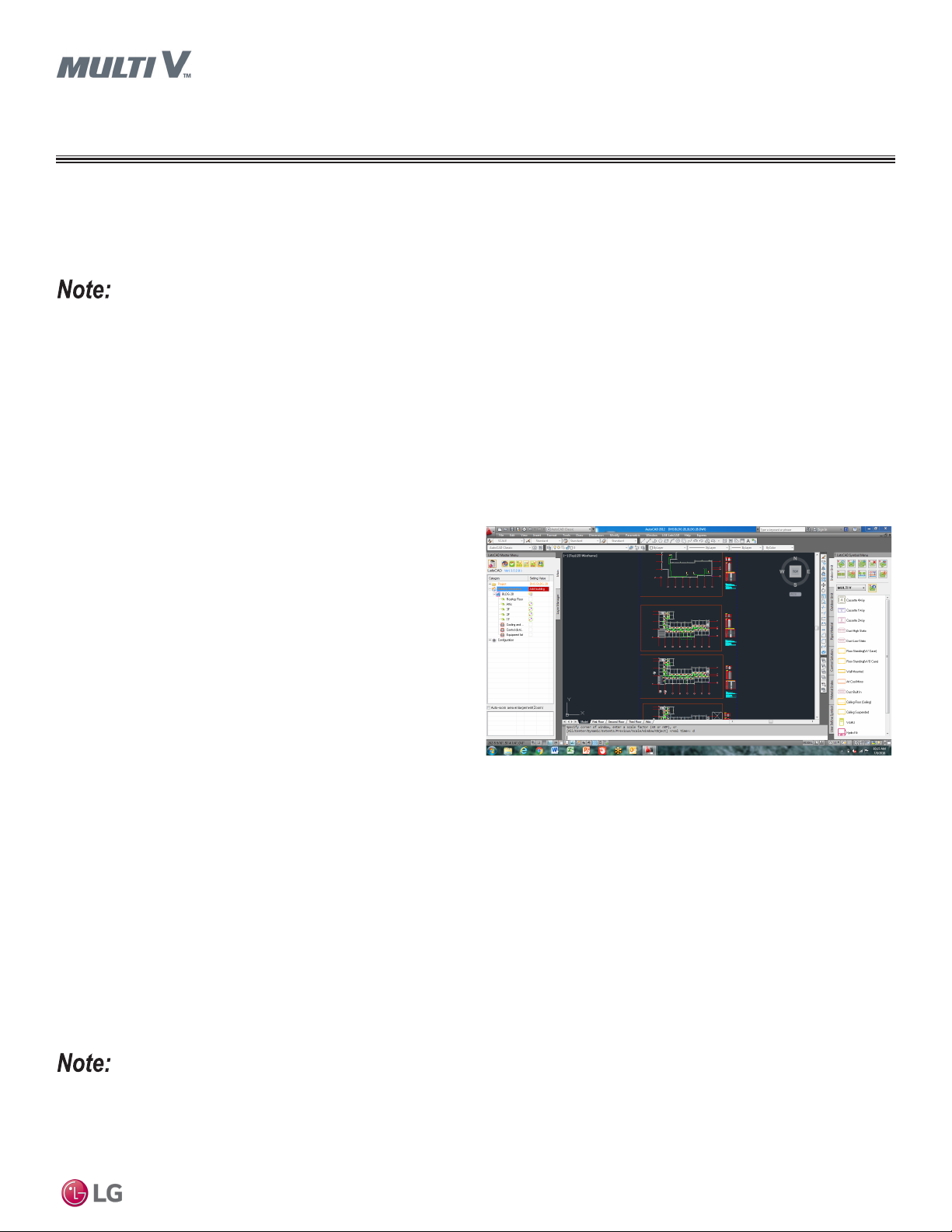
LATS CAD2 combines the LG LATS program with AutoCAD®
software**. It permits engineers to layout and validate LG Multi V
Variable Refrigerant Flow (VRF), Multi F / Multi F MAX, Single-Zone,
and Energy Recovery Ventilator (ERV) systems directly into CAD
drawings.
LATS Revit integrates the LG LATS program with Revit® software**.
It permits engineers to layout and validate Multi V VRF systems
directly into Revit drawings.
**AutoCAD® and Revit® are both registered marks of Autodesk, Inc.
Figure 1:Example of LATS CAD2.
Features
All LG product design criteria have been loaded into the program,
making LATS simple to use: double click or drag and drop the component choices. Build systems in Tree Mode where the refrigerant
system can be viewed. Switch to a Schematic diagram to see the electrical and communications wiring.
LATS software permits the user to input region data, indoor and outdoor design temperatures, modify humidity default values, zoning, specify
type and size of outdoor units and indoor units, and input air flow and external static pressure (ESP) for ducted indoor units.
The program can also:
• Import building loads from a separate Excel file.
• Present options for outdoor unit auto selection.
• Automatically calculate component capacity based on design
conditions for the chosen region.
• Verify if the height differences between the various system
components are within system limits.
• Provide the correct size of each refrigerant piping segment and LG
Y-Branches and Headers.
• Adjust overall piping system length when elbows are added.
• Check for component piping limitations and flag if any parameters
are broken.
• Factor operation and capacity for defrost operation.
• Calculate refrigerant charge, noting any additional trim charge.
• Suggest accessories for indoor units and outdoor units.
• Run system simulation.
Introduction
Features depend on which LATS program is being used, and the type of system being designed.
Due to our policy of continuous product innovation, some specications may change without notication.
© LG Electr onics U.S.A., Inc., Englewood Cl iffs, NJ. All r ights reserved. “LG” is a registered tra demark of LG Corp.
INTRODUCTION | 5
LG AIR CONDITIONER
TECHNICAL SOLUTION (LATS)
LATS Generates a Complete Project Report
LATS software also generates a report containing project design parameters, cooling and heating design data, system component performance, and capacity data. The report includes system combination ratio and refrigerant charge calculations; and provides detailed bill of
material, including outdoor units, indoor units, control devices, accessories, refrigerant pipe sizes segregated by building, by system, by pipe
size, and by pipe segments. LATS can generate an Excel GERP report that can imported into the LG SOPS pricing and ordering system.
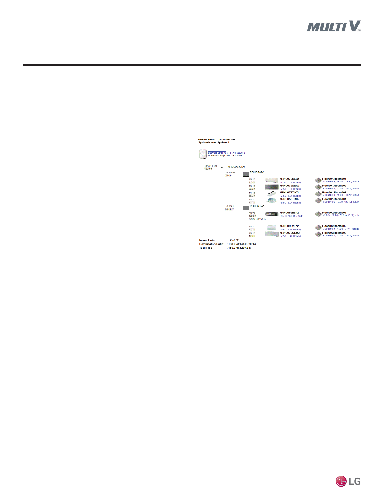
Proper Design to Install Procedure
LG encourages a two report design-to-install-procedure. After the
design engineer determines building / zone loads and other details,
the engineer opens the LATS program and inputs the project’s information. When the design is complete, the “Auto Piping” and “System
Check” functions must be used to verify piping sizes, limitations, and
if any design errors are present. If errors are found, engineers must
adjust the design, and run Auto Piping and System Check again.
When the design passes the checks, then the engineer prints out
a project “Shop Drawing” (LATS Tree Diagram) and provides it to
the installing contractor. The contractor must follow the LATS Tree
Diagram when building the piping system, but oftentimes the design
changes on the building site:
Figure 2:Example of a LATS Tree Diagram.
• Architect has changed location and/or purpose of room(s).
• Outdoor unit cannot be placed where originally intended.
• Structural elements prevent routing the piping as planned.
• Air conditioning system conflicts with other building systems
(plumbing, gas lines, etc.).
The contractor must mark any deviation from the design on the Shop Drawing, including as-built straight lines and elbows. This “Mark Up”
drawing must be returned to the design engineer or Rep, who must input contractor changes into the LATS file. (Copy the original LATS software file, save and rename as a separate file, and modify all piping lengths by double-clicking on each length and editing information.) Like
the shop drawing, the Auto Piping and System Check must also be run on this new “As Built” drawing. The design engineer or Rep must then
provide the final As Built file to the contractor. The Mark Up version must be compared to the As Built version for:
• Differences in pipe diameter(s). If incorrect diameters have been installed, the piping must be changed out. If pipe diameters have changed,
check to see if Y-Branches will also need to be changed.
• Changes to outdoor unit and indoor unit capacities. Capacities changes may impact line length changes.
• Additional refrigerant charge quantity (“Trim Charge”). Trim charge will change if piping lengths and diameters change. The As Built version
must reflect installed piping lengths to ensure correct trim charge.
MULTI V Ducted Indoor Unit Engineering Manual
All documents submitted by the contractor, as well as the Shop Drawing and the As Built Drawing files must be provided for commissioning
purposes. Model and serial numbers for all system components must also be submitted. If the steps previously detailed are not followed,
and all documents are not provided to the commissioning agent, the project runs the risk of not being commissioned and voiding any limited
warranty LG offers on the equipment.
6 | INTRODUCTION
Due to our policy of continuous product innovation, some specications may change without notication.
© LG Electr onics U.S.A., Inc., Englewood Cl iffs, NJ. All r ights reserved. “LG” is a registered tra demark of LG Corp.

REFRIGERANT CHARGE WORKSHEET
Multi V 5 System R410A Refrigerant Charge Calculator (lbs.)
Job Name: __________________________________________
System Tag or ID:
Project Manager: ____________________________________ Date: ______________
Line # Description Chassis I.D. Size Quantity CF (Ref.)
1 Linear feet of 1/4" liquid line tubing
2 Linear feet of 3/8" liquid line tubing
3 Linear feet of 1/2" liquid line tubing
4 Linear feet of 5/8" liquid line tubing
5 Linear feet of 3/4" liquid line tubing
6 Linear feet of 7/8" liquid line tubing
7 Linear feet of 1" liquid line tubing
8 Standard + Art Cool Mirror SJ, SK 5k to 15k 0.53
9 Standard + Art Cool Mirror SJ, SK 18k to 24k 0.62
10 Standard SV 30k to 36k 1.01
11 Art Cool Gallery SF 9k to 12k 0.22
12 1-Way Cassette TU 7k to 12k 0.44
13 1-Way Cassette TT 18k to 24k 0.64
14 2-Way Cassette TS 18k to 24k 0.75
15 4-Way 2' x 2' Cassette TR 5k to 7k 0.40
16 4-Way 2' x 2' Cassette TR 9k to 12k 0.55
17 4-Way 2' x 2' Cassette TQ 15k to 18k 0.71
18 4-Way 3' x 3' Cassette TN 7k to 24k 0.88
19 4-Way 3' x 3' Cassette TM 28k to 36k 1.08
20 4-Way 3’ x 3’ Cassette TM 42k to 48k 1.41
21 High Static Ducted BH 7k to 24k 0.57
22 High Static Ducted M2 7k to 24k 0.77
23 High Static Ducted M2 28k to 42k 1.15
24 High Static Ducted M3 28k to 54k 1.35
25 High Static Ducted B8 36k to 96k 2.20
26 Low Static Ducted, Low Static Ducted Bottom Return L1 5k to 9k 0.31
27 Low Static Ducted, Low Static Ducted Bottom Return L2 12k to 18k 0.42
28 Low Static Ducted, Low Static Ducted Bottom Return L3 21k to 24k 0.55
29 Vertical / Horizontal Air Handling Unit NJ 12k to 30k 1.04
30 Vertical / Horizontal Air Handling Unit NJ 36k 1.57
31 Vertical / Horizontal Air Handling Unit NK 42k to 54k 2.00
32 Floor Standing CE (U) 7k to 15k 0.37
33 Floor Standing CF (U) 18k to 24k 0.82
34 HRU: PRHR022A/023A, 032A/033A, 042A/043A, 063A, 083A — — 1.1
35 ADDITIONAL Refrigerant Charge Required (Sum of lines 1 – 34)
36 Outdoor Unit Factory Refrigerant Charge
37
38
1
CF (Ref.) = Correction Factor for Refrigerant Charge. 2For refrigerant charge purposes, consider only the liquid line; ignore the vapor line(s).
Total ODU FACTORY Refrigerant Charge (Sum of factory refrigerant charges for all ODUs in the system, lines 36A -36H)
Sum of Additional Refrigerant Charge Required (line 35) and Total ODU Factory Refrigerant Charge (line 37)
2
2
2
2
2
2
2
— — 0.015
— — 0.041
— — 0.079
— — 0.116
— — 0.179
— — 0.238
— — 0.323
36A ARUM072*TE5 72k 14.3
36B ARUM096*TE5 96k 23.2
36C ARUM121*TE5 121k 23.2
36D ARUM144*TE5 144k 26.5
36E ARUM168*TE5 168k 26.5
36F ARUM192*TE5 192k 30.9
36G ARUM216*TE5 216k 37.5
36H ARUM241*TE5 241k 37.5
TOTAL SYSTEM CHARGE
1
Total (lbs.)
Introduction
Due to our policy of continuous product innovation, some specications may change without notication.
© LG Electr onics U.S.A., Inc., Englewood Cl iffs, NJ. All r ights reserved. “LG” is a registered tra demark of LG Corp.
INTRODUCTION | 7

REFRIGERANT CHARGE WORKSHEET
Water IV System R410A Refrigerant Charge Calculator (lbs.)
Job Name: __________________________________________
System Tag or ID:
Project Manager: ____________________________________ Date: ______________
Line # Description Chassis I.D. Size Quantity CF (Ref.)
1 Linear feet of 1/4" liquid line tubing
2 Linear feet of 3/8" liquid line tubing
3 Linear feet of 1/2" liquid line tubing
4 Linear feet of 5/8" liquid line tubing
5 Linear feet of 3/4" liquid line tubing
6 Linear feet of 7/8" liquid line tubing
7 Linear feet of 1" liquid line tubing
8 Standard + Art Cool Mirror SJ, SK 5k to 15k 0.53
9 Standard + Art Cool Mirror SJ, SK 18k to 24k 0.62
10 Standard SV 30k to 36k 1.01
11 Art Cool Gallery SF 9k to 12k 0.22
12 1-Way Cassette TU 7k to 12k 0.44
13 1-Way Cassette TT 18k to 24k 0.64
14 2-Way Cassette TS 18k to 24k 0.75
15 4-Way 2' x 2' Cassette TR 5k to 7k 0.40
16 4-Way 2' x 2' Cassette TR 9k to 12k 0.55
17 4-Way 2' x 2' Cassette TQ 15k to 18k 0.71
18 4-Way 3' x 3' Cassette TN 7k to 24k 0.88
19 4-Way 3' x 3' Cassette TM 28k to 36k 1.08
20 4-Way 3’ x 3’ Cassette TM 42k to 48k 1.41
21 High Static Ducted BH 7k to 24k 0.57
22 High Static Ducted M2 7k to 24k 0.77
23 High Static Ducted M2 28k to 42k 1.15
24 High Static Ducted M3 28k to 54k 1.35
25 High Static Ducted B8 36k to 96k 2.20
26 Low Static Ducted, Low Static Ducted Bottom Return L1 5k to 9k 0.31
27 Low Static Ducted, Low Static Ducted Bottom Return L2 12k to 18k 0.42
28 Low Static Ducted, Low Static Ducted Bottom Return L3 21k to 24k 0.55
29 Vertical / Horizontal Air Handling Unit NJ 12k to 30k 1.04
30 Vertical / Horizontal Air Handling Unit NJ 36k 1.57
31 Vertical / Horizontal Air Handling Unit NK 42k to 54k 2.00
32 Floor Standing CE (U) 7k to 15k 0.37
33 Floor Standing CF (U) 18k to 24k 0.82
34 HRU: PRHR022A/023A, 032A/033A, 042A/043A, 063A, 083A — — 1.1
35 ADDITIONAL Refrigerant Charge Required (Sum of lines 1 – 34)
MULTI V Ducted Indoor Unit Engineering Manual
36
37
38
1
CF (Ref.) = Correction Factor for Refrigerant Charge. 2For refrigerant charge purposes, consider only the liquid line; ignore the vapor line(s).
Water-Source Unit Factory
Refrigerant Charge
Total WSU FACTORY Refrigerant Charge (Sum of factory refrigerant charges for all WSUs in the system)
Sum of Additional Refrigerant Charge Required (line 35) and Total WSU Factory Refrigerant Charge (line 37)
2
2
2
2
2
2
2
— — 0.015
— — 0.041
— — 0.079
— — 0.116
— — 0.179
— — 0.238
— — 0.323
ARW*072BAS4, ARW*096BAS4, ARW*121BAS4, ARW*144BAS4 10.42
ARW*072DAS4, ARW*096DAS4, ARW*121DAS4 10.42
ARW*144DAS4, ARW*192DAS4 11.66
TOTAL SYSTEM CHARGE
1
Total (lbs.)
8 | INTRODUCTION
Due to our policy of continuous product innovation, some specications may change without notication.
© LG Electr onics U.S.A., Inc., Englewood Cl iffs, NJ. All r ights reserved. “LG” is a registered tra demark of LG Corp.

REFRIGERANT CHARGE WORKSHEET
Multi V S System R410A Refrigerant Charge Calculator (lbs.)
Job Name: __________________________________________
System Tag or ID:
Project Manager: ____________________________________ Date: ______________
Line # Description Chassis I.D. Size Quantity CF (Ref.)
1 Linear feet of 1/4" liquid line tubing
2 Linear feet of 3/8" liquid line tubing
3 Linear feet of 1/2" liquid line tubing
4 Linear feet of 5/8" liquid line tubing
5 Linear feet of 3/4" liquid line tubing
6 Linear feet of 7/8" liquid line tubing
7 Linear feet of 1" liquid line tubing
8 Standard + Art Cool Mirror SJ, SK 5k to 15k 0.53
9 Standard + Art Cool Mirror SJ, SK 18k to 24k 0.62
10 Standard SV 30k to 36k 1.01
11 Art Cool Gallery SF 9k to 12k 0.22
12 1-Way Cassette TU 7k to 12k 0.44
13 1-Way Cassette TT 18k to 24k 0.64
14 2-Way Cassette TS 18k to 24k 0.75
15 4-Way 2' x 2' Cassette TR 5k to 7k 0.40
16 4-Way 2' x 2' Cassette TR 9k to 12k 0.55
17 4-Way 2' x 2' Cassette TQ 15k to 18k 0.71
18 4-Way 3' x 3' Cassette TN 7k to 24k 0.88
19 4-Way 3' x 3' Cassette TM 28k to 36k 1.08
20 4-Way 3’ x 3’ Cassette TM 42k to 48k 1.41
21 High Static Ducted BH 7k to 24k 0.57
22 High Static Ducted M2 7k to 24k 0.77
23 High Static Ducted M2 28k to 42k 1.15
24 High Static Ducted M3 28k to 54k 1.35
25 High Static Ducted B8 36k to 96k 2.20
26 Low Static Ducted, Low Static Ducted Bottom Return L1 5k to 9k 0.31
27 Low Static Ducted, Low Static Ducted Bottom Return L2 12k to 18k 0.42
28 Low Static Ducted, Low Static Ducted Bottom Return L3 21k to 24k 0.55
29 Vertical / Horizontal Air Handling Unit NJ 12k to 30k 1.04
30 Vertical / Horizontal Air Handling Unit NJ 36k 1.57
31 Vertical / Horizontal Air Handling Unit NK 42k to 54k 2.00
32 Floor Standing CE (U) 7k to 15k 0.37
33 Floor Standing CF (U) 18k to 24k 0.82
34 HRU: PRHR022A/023A, 032A/ 033A, 042A/ 043A, 063A, 083A — — 1.1
35 ADDITIONAL Refrigerant Charge Required (Sum of lines 1 – 34)
36
37
1
CF (Ref.) = Correction Factor for Refrigerant Charge. 2For refrigerant charge purposes, consider only the liquid line; ignore the vapor line(s).
Total ODU FACTORY Refrigerant Charge
(Choose One)
Sum of Additional Refrigerant Charge Required (line 35) and Total ODU Factory Refrigerant Charge (from lines 36A through 36G)
2
2
2
2
2
2
2
— — 0.015
— — 0.041
— — 0.079
— — 0.116
— — 0.179
— — 0.238
— — 0.323
36A ARUN024GSS4 0
36B ARUN038GSS4 0
36C ARUN048GSS4 0
36D ARUN053GSS4 0
36F ARUN060GSS4 0
36G ARUB060GSS4 0
TOTAL SYSTEM CHARGE
1
Total (lbs.)
Introduction
Due to our policy of continuous product innovation, some specications may change without notication.
© LG Electr onics U.S.A., Inc., Englewood Cl iffs, NJ. All r ights reserved. “LG” is a registered tra demark of LG Corp.
INTRODUCTION | 9
CEILING-CONCEALED
DUCTED
HIGH STATIC
Mechanical Specifications on page 11
General Data on page 12
Electrical Data on page 17
External Dimensions on page 18
Electrical Wiring Diagrams on page 22
Refrigerant Flow Diagrams on page 30
External Static Pressure and Air Flow on page 32
External Static Pressure Ranges on page 38
Acoustic Data on page 43
Capacity Tables on page 74
Optional Accessories on page 124

DUCTED HIGH STATIC
Mechanical Specications
Casing
The case is designed to mount concealed above a finished ceiling.
Fan supply air is front horizontal with a dedicated rear horizontal
return. The unit is manufactured with coated metal. Cold surfaces
are covered with a coated polystyrene insulating material. The cold
surface areas of the case are covered externally with sheet insulation made of Ethylene Propylene Diene Monomer (M-Class) (EPDM)
conforming to ASTM Standard D-1418. The case is provided with
hanger brackets designed to support the unit weight on four corners.
Hanger brackets have pre-punched holes designed to accept field
supplied, all-thread rod hangers.
Fan Assembly and Control
The unit has Sirocco fans made of high strength ABS GP-2200
polymeric resin. Fans are directly driven and mounted on a common
shaft. The fan motor is a Brushless Digitally Controlled (BLDC)
design with permanently lubricated and sealed ball bearings. The
fan motor includes thermal, overcurrent and low RPM protection.
The fan / motor assembly is mounted on vibration attenuating rubber
grommets. The fan impeller is statically and dynamically balanced.
The fan speed is controlled using a microprocessor based, direct
digital control algorithm that provides a high fan speed in cooling
thermal ON and low fan speed in cooling thermal OFF, high fan
speed in heating thermal ON and fan off in heating thermal OFF. The
fan speeds can be field adjusted between low, medium, and high
speeds and DIP switch settings will allow the fan to run constantly
during defrost or oil return modes. Each setting can be field adjusted
from the factory setting (RPM / ESP) to compensate for additional
resistance to airflow caused by field connected ductwork or other
airflow restricting devices.
Air Filter
Return air is filtered with a removable, washable filter with antifungal
treatment. MERV 13 filter modules with plenums available.
Microprocessor Controls
The unit is provided with an integrated microprocessor-based controller. The controller is capable of performing functions necessary
to operate the system without the use of a wall-mounted controller.
A temperature thermistor is factory-mounted in the return air stream.
All unit operation parameters, excluding the unit operating schedule,
are stored in non-volatile memory resident on the unit microprocessor. Operating schedules are stored in select models of the optional,
wall-mounted, local, or central controller. The field supplied communication cable between the indoor unit(s) and outdoor unit is to be
a minimum of 18 AWG, 2-conductor, stranded, and shielded cable
(RS-485), terminated via screw terminals on the control boards.
The microprocessor control provides the following functions: auto
addressing, self-diagnostics, auto restart following power restoration,
test run, and will operate the indoor unit using one of five operating
modes:
1. Auto Changeover (Heat Recovery only)
2. Heating
3. Cooling
4. Dry
5. Fan Only
For Heat Recovery systems the Auto Changeover setting automatically switches control of the indoor unit between cooling and heating
modes based on space temperature conditions.
For Heat Pump systems, heated or cooled air delivery is dependent
upon outdoor unit operating mode.
Due to our policy of continuous product innovation, some specications may change without notication.
© LG Electr onics U.S.A., Inc., Englewood Cl iffs, NJ. All r ights reserved. “LG” is a registered tra demark of LG Corp.
In Heating mode, the
microprocessor control
will activate the indoor unit
when indoor room
temperature falls below
setpoint temperature and
signals the outdoor unit to begin heating cycle. The indoor unit fan
operation is delayed until coil pipe temperature reaches 76ºF. Significant airflow is generated when pipe temperature reaches 80°F. In
lieu of factory return air thermistor, screw terminals on the microprocessor circuit board accommodate various models of wall-mounted
local controllers and/or a wall-mounted remote temperature sensor.
The unit microprocessor is capable of accepting space temperature
readings concurrently or individually from either:
1. Wall-mounted wired controller(s)
2. Factory mounted return air thermistor or the optional wall mounted wired remote temperature sensor
A single indoor unit has the capability of being controlled by up to
two local wired controllers. The microprocessor controls space
temperature using the value provided by the temperature sensor
sensing a space temperature that is farthest away from the temperature set-point. The microprocessor control provides a cooling or
heating mode test cycle that operates the unit for 18 minutes without
regard to the space temperature. If the system is provided with an
optional wall-mounted local or central controller, displayed diagnostic
codes are specific, alpha numeric, and provide the service technician
with a reason for the code displayed.
Condensate Lift/Pump
The indoor unit is provided with a factory installed and wired condensate lift/pump capable of providing a minimum 27.5 inch lift from the
bottom exterior surface of the unit casing. The unit drain pan is provided with a secondary drain port/plug allowing the pan to be drained
for service. The lift pump comes with a safety switch that will shut off
indoor unit if condensate rises too high in the drain pan.
Condensate Drain Pan
The condensate drain pan is constructed of high impact polystyrene
resin (HIPS).
Coil
The indoor unit coil is constructed with grooved design copper tubes
with slit coil fins, two (2) to three (3) rows, nineteen (19) to
twenty-one (21) fins per inch.
Controls Features
• Auto changeover
(Heat Recovery only)
• Auto operation
• Auto restart
• External on/off control
• Dual thermistor control
• Dual setpoint control*
• Filter life display*
• Multiple auxiliary heater
applications*
• Group control
• External static pressure control
• Hot start
• Self diagnostics
• Timer (on / off)
• Weekly schedule
• Fan speed control
• Ventilation (outside air)
• Wi-Fi compatible
• Auto fan
• Leak detection
*To enable Generation 4 features, outdoor unit DIP Switch No. 3 must be set
to ON. Please refer to the Multi V IV,
Multi V Water IV, Multi V S Engineering
Manual for additional information.
HIGH STATIC | 11
Ducted High Static
DUCTED HIGH STATIC
General Data
BH Units
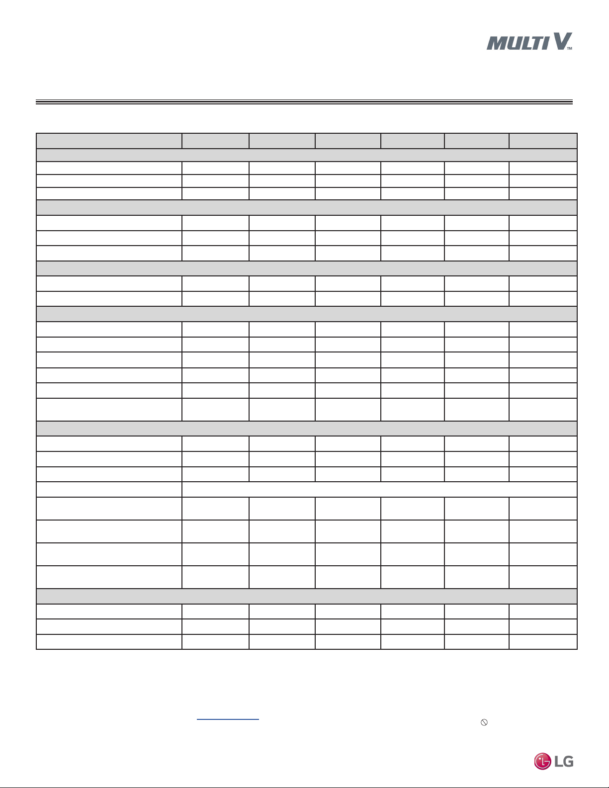
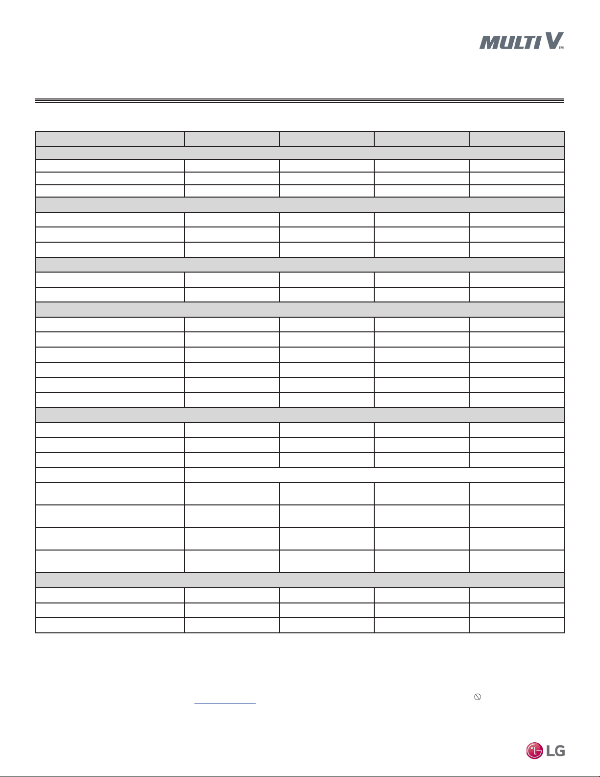
Table 1: Ducted High Static (BH Frame) Indoor Unit General Data.
Model No. ARNU073BHA4 ARNU093BHA4 ARNU123BHA4 ARNU153BHA4 ARNU183BHA4 ARNU243BHA4
Cooling Mode Performance
Capacity (Btu/h)
Power Input1 (W)
L/M/H Power Input at Factory Default (W)
Heating Mode Performance
Capacity (Btu/h)
Power Input1 (W)
L/M/H Power Input at Factory Default (W)
Entering Mixed Air
Cooling Max. (°F WB)
Heating Min. (°F DB)
2
Unit Data
Refrigerant Type3
Refrigerant Control
Sound Pressure4 dB(A) (H/M/L)
Net Unit Weight (lbs.)
Shipping Weight (lbs.)
Communication Cable5
(No. x AWG)
Fan
Type
Motor
Housing
Motor/Drive
Airflow Rate H/M/L (CFM)
Standard Mode
Airflow Rate H/M/L (CFM)
High Mode (Factory Set)
MULTI V Ducted Indoor Unit Engineering Manual
External Static Pressure (in. wg)
Standard Mode
External Static Pressure (in. wg)
High Mode (Factory Set)
Piping
Liquid Line (in., O.D.)
Vapor Line (in., O.D.)
Condensate Line (in., I.D.)
EEV: Electronic Expansion Valve
Power wiring is field supplied and must comply with the applicable local and national
codes.
This unit comes with a dry nitrogen charge.
All capacities are net with a combination ratio between 95-105%.
Rated capacity is certified under AHRI Standard 1230. Ratings are subject to change
without notice. Current certified ratings are available at www.ahridirectory.org.
1
Max. power input is rated at maximum setting value.
2
Low ambient performance with LGRED° heat technology is included in Multi V 5 Air
7,500 9,600 12,300 15,400 19,100 24,200
150 150 150 150 150 150
49 / 52 / 58 52 / 58 / 67 58 / 67 / 78 58 / 78 / 90 78 / 90 / 103 103 / 117 / 132
8,500 10,900 13,600 17,100 21,500 27,300
150 150 150 150 150 150
49 / 52 / 58 52 / 58 / 67 58 / 67 / 78 58 / 78 / 90 78 / 90 / 103 103 / 117 / 132
76 76 76 76 76 76
59 59 59 59 59 59
R410A R410A R410A R410A R410A R410A
EEV EEV EEV EEV EEV EEV
34 / 33 / 32 35 / 34 / 33 37 / 35 / 34 39 / 37 / 34 40 / 38 / 37 42 / 41 / 40
58.4 58.4 58.4 58.4 58.4 58.4
68.3 68.3 68.3 68.3 68.3 68.3
2 x 18 2 x 18 2 x 18 2 x 18 2 x 18 2 x 18
Sirocco Sirocco Sirocco Sirocco Sirocco Sirocco
1 1 1 1 1 1
2 2 2 2 2 2
258 / 222 / 198 258 / 222 / 198 307 / 258 / 198 388 / 357 / 307 466 / 413 / 258 618 / 519 / 445
230 / 205 / 191 286 / 230 / 205 339 / 286 / 230 399 / 339 / 230 459 / 399 / 339 565 / 509 / 459
0.23 0.23 0.23 0.23 0.23 0.23
0.31 0.31 0.31 0.31 0.31 0.31
1/4 Flare 1/4 Flare 1/4 Flare 1/4 Flare 1/4 Flare 3/8 Flare
1/2 Flare 1/2 Flare 1/2 Flare 1/2 Flare 1/2 Flare 5/8 Flare
1 1 1 1 1 1
Brushless Digitally Controlled / Direct
Source Units produced after February 2019.
3
Take appropriate actions at the end of HVAC equipment life to recover, recycle, reclaim or
destroy R410A refrigerant according to applicable regulations (40 CFR Part 82, Subpart F)
under section 608 of CAA.
4
Sound Pressure levels are tested in an anechoic chamber under ISO Standard 3745.
5
All communication cable to be minimum 18 AWG, 2-conductor, twisted, stranded, shielded
and must comply with applicable local and national codes. Ensure the communication
cable is properly grounded at the master outdoor unit only. Do not ground the ODU-IDU
communication cable at any other point.
12 | HIGH STATIC
Due to our policy of continuous product innovation, some specications may change without notication.
© LG Electr onics U.S.A., Inc., Englewood Cl iffs, NJ. All r ights reserved. “LG” is a registered tra demark of LG Corp.

Table 2: Ducted High Static (M2 Frame) Indoor Unit General Data.
Model No. ARNU073M2A4 ARNU093M2A4 ARNU123M2A4 ARNU153M2A4 ARNU183M2A4
Cooling Mode Performance
Capacity (Btu/h)
Max Power Input1 (W)
L/M/H Power Input at Factory Default (W)
7,500 9,600 12,300 15,400 19,100
430 430 430 430 430
21 / 29 / 38 21 / 29 / 38 25 / 34 / 43 25 / 34 / 43 34 / 43 / 67
Heating Mode Performance
Capacity (Btu/h)
Max Power Input1 (W)
L/M/H Power Input at Factory Default (W)
8,500 10,900 13,600 17,100 21,500
430 430 430 430 430
21 / 29 / 38 21 / 29 / 38 25 / 34 / 43 25 / 34 / 43 34 / 43 / 67
Entering Mixed Air
Cooling Max. (°F WB)
Heating Min. (°F DB)2
76 76 76 76 76
59 59 59 59 59
Unit Data
Refrigerant Type3
Refrigerant Control
Sound Pressure4 dB(A) (H/M/L)
Net Unit Weight (lbs.)
Shipping Weight (lbs.)
Communication Cable5 (No. x AWG)
R410A R410A R410A R410A R410A
EEV EEV EEV EEV EEV
38 / 37 / 36 38 / 37 / 36 38 / 37 / 36 38 / 37 / 36 39 / 38 / 37
82.9 82.9 82.9 82.9 82.9
95.5 95.5 95.5 95.5 95.5
2 x 18 2 x 18 2 x 18 2 x 18 2 x 18
Fan
Type
Motor
Housing
Sirocco Sirocco Sirocco Sirocco Sirocco
1 1 1 1 1
2 2 2 2 2
Motor/Drive
Airflow Rate H/M/L (CFM)
Standard Mode
Airflow Rate H/M/L (CFM)
High Mode (Factory Set)
External Static Pressure (in. wg)
Standard Mode
External Static Pressure (in. wg)
High Mode (Factory Set)
477 / 399 / 327 477 / 399 / 327 520 / 435 / 363 520 / 435 / 363 640 / 520 / 435
468 / 381 / 294 468 / 381 / 294 512 / 425 / 337 512 / 425 / 337 673 / 512 / 425
0.20 0.20 0.20 0.20 0.20
0.24 0.24 0.24 0.24 0.24
Piping
Liquid Line (in., O.D.)
Vapor Line (in., O.D.)
Condensate Line (in., I.D.)
EEV: Electronic Expansion Valve
Power wiring is field supplied and must comply with the applicable local and national
codes.
This unit comes with a dry nitrogen charge.
All capacities are net with a combination ratio between 95-105%.
Rated capacity is certified under AHRI Standard 1230. Ratings are subject to change
without notice. Current certified ratings are available at www.ahridirectory.org.
1
Max. power input is rated at maximum setting value.
2
Low ambient performance with LGRED° heat technology is included in Multi V 5 Air
Source Units produced after February 2019.
1/4 Flare 1/4 Flare 1/4 Flare 1/4 Flare 1/4 Flare
1/2 Flare 1/2 Flare 1/2 Flare 1/2 Flare 1/2 Flare
1 1 1 1 1
DUCTED HIGH STATIC
General Data
M2 Units
Brushless Digitally Controlled / Direct
3
Take appropriate actions at the end of HVAC equipment life to recover, recycle, reclaim or
destroy R410A refrigerant according to applicable regulations (40 CFR Part 82, Subpart F)
under section 608 of CAA.
4
Sound Pressure levels are tested in an anechoic chamber under ISO Standard 3745.
5
All communication cable to be minimum 18 AWG, 2-conductor, twisted, stranded, shielded
and must comply with applicable local and national codes. Ensure the communication
cable is properly grounded at the master outdoor unit only. Do not ground the ODU-IDU
communication cable at any other point.
Ducted High Static
Due to our policy of continuous product innovation, some specications may change without notication.
© LG Electr onics U.S.A., Inc., Englewood Cl iffs, NJ. All r ights reserved. “LG” is a registered tra demark of LG Corp.
HIGH STATIC | 13
DUCTED HIGH STATIC
General Data
M2 Units
Table 3: Ducted High Static (M2 Frame) Indoor Unit General Data, continued.
Model No. ARNU243M2A4 ARNU283M2A4 ARNU363M2A4 ARNU423M2A4
Cooling Mode Performance
Capacity (Btu/h)
Max Power Input1 (W)
L/M/H Power Input at Factory Default (W)
Heating Mode Performance
Capacity (Btu/h)
Max Power Input1 (W)
L/M/H Power Input at Factory Default (W)
Entering Mixed Air
Cooling Max. (°F WB)
Heating Min. (°F DB)
2
Unit Data
Refrigerant Type3
Refrigerant Control
Sound Pressure4 dB(A) (H/M/L)
Net Unit Weight (lbs.)
Shipping Weight (lbs.)
Communication Cable5 (No. x AWG)
Fan
Type
Motor
Housing
Motor/Drive
Airflow Rate H/M/L (CFM)
Standard Mode
Airflow Rate H/M/L (CFM)
High Mode (Factory Set)
External Static Pressure (in. wg)
MULTI V Ducted Indoor Unit Engineering Manual
Standard Mode
External Static Pressure (in. wg)
High Mode (Factory Set)
Piping
Liquid Line (in., O.D.)
Vapor Line (in., O.D.)
Condensate Line (in., I.D.)
EEV: Electronic Expansion Valve
Power wiring is field supplied and must comply with the applicable local and national
codes.
This unit comes with a dry nitrogen charge.
All capacities are net with a combination ratio between 95-105%.
Rated capacity is certified under AHRI Standard 1230. Ratings are subject to change
without notice. Current certified ratings are available at www.ahridirectory.org.
1
Max. power input is rated at maximum setting value.
2
Low ambient performance with LGRED° heat technology is included in Multi V 5 Air
Source Units produced after February 2019.
24,200 28,000 36,200 42,000
430 430 430 430
34 / 43 / 67 57 / 88 / 123 88 / 123 / 184 136 / 193 / 231
27,300 31,500 40,600 47,000
450 450 450 450
34 / 43 / 67 57 / 88 / 123 88 / 123 / 184 136 / 193 / 231
76 76 76 76
59 59 59 59
R410A R410A R410A R410A
EEV EEV EEV EEV
39 / 38 / 37 40 / 38 / 37 42 / 40 / 38 44 / 43 / 40
82.9 86.2 86.2 86.2
95.5 99.2 99.2 99.2
2 x 18 2 x 18 2 x 18 2 x 18
Sirocco Sirocco Sirocco Sirocco
1 1 1 1
2 2 2 2
640 / 520 / 435 892 / 770 / 645 1,021 / 844 / 695 1,262 / 1,087 / 917
673 / 512 / 425 845 / 676 / 528 1,031 / 845 / 676 1,260 / 1,076 / 888
0.20 0.20 0.20 0.20
0.24 0.24 0.24 0.24
3/8 Flare 3/8 Flare 3/8 Flare 3/8 Flare
5/8 Flare 5/8 Flare 5/8 Flare 5/8 Flare
1 1 1 1
Brushless Digitally Controlled / Direct
3
Take appropriate actions at the end of HVAC equipment life to recover, recycle, reclaim or
destroy R410A refrigerant according to applicable regulations (40 CFR Part 82, Subpart F)
under section 608 of CAA.
4
Sound Pressure levels are tested in an anechoic chamber under ISO Standard 3745.
5
All communication cable to be minimum 18 AWG, 2-conductor, twisted, stranded, shielded
and must comply with applicable local and national codes. Ensure the communication
cable is properly grounded at the master outdoor unit only. Do not ground the ODU-IDU
communication cable at any other point.
14 | HIGH STATIC
Due to our policy of continuous product innovation, some specications may change without notication.
© LG Electr onics U.S.A., Inc., Englewood Cl iffs, NJ. All r ights reserved. “LG” is a registered tra demark of LG Corp.

Table 4: Ducted High Static (M3 Frames) Indoor Unit General Data.
Model No. ARNU283M3A4 ARNU363M3A4 ARNU423M3A4 ARNU483M3A4 ARNU543M3A4
Cooling Mode Performance
Capacity (Btu/h)
Max Power Input1 (W)
L/M/H Power Input at Factory Default (W)
28,000 36,200 42,000 48,100 54,000
650 650 650 650 650
60 / 83 / 109 75 / 107 / 161 75 / 107 / 161 75 / 107 / 172 172 / 215 / 260
Heating Mode Performance
Capacity (Btu/h)
Power Input1 (W)
L/M/H Power Input at Factory Default (W)
31,500 40,600 47,000 54,200 61,400
650 650 650 650 650
60 / 83 / 109 75 / 107 / 161 75 / 107 / 161 75 / 107 / 172 172 / 215 / 260
Entering Mixed Air
Cooling Max. (°F WB)
Heating Min. (°F DB)
2
76 76 76 76 76
59 59 59 59 59
Unit Data
Refrigerant Type3
Refrigerant Control
Sound Pressure4 dB(A) (H/M/L)
Net Unit Weight (lbs.)
Shipping Weight (lbs.)
Communication Cable5 (No. x AWG)
R410A R410A R410A R410A R410A
EEV EEV EEV EEV EEV
40/39/37 41/39/37 41/39/37 42/39/37 44/43/42
96.1 96.1 96.1 96.1 96.1
110.0 110.0 110.0 110.0 110.0
2 x 18 2 x 18 2 x 18 2 x 18 2 x 18
Fan
Type
Motor
Housing
Sirocco Sirocco Sirocco Sirocco Sirocco
1 1 1 1 1
2 2 2 2 2
Motor/Drive
Airflow Rate H/M/L (CFM)
Standard Mode
Airflow Rate H/M/L (CFM)
High Mode (Factory Set)
External Static Pressure (in. wg)
Standard Mode
External Static Pressure (in. wg)
High Mode (Factory Set)
1,235 / 1,060 / 915 1,327 / 1,097 / 952 1,327 / 1,097 / 952 1,457 / 1,189 / 952 1,720 / 1,558 / 1,424
1,250 / 1,017 / 837 1,449 / 1,191 / 918 1,449 / 1,191 / 918 1,482 / 1,191 / 918 1,744 / 1,614 / 1,482
0.19 0.19 0.19 0.19 0.19
0.23 0.23 0.23 0.23 0.23
Piping
Liquid Line (in., O.D.)
Vapor Line (in., O.D.)
Condensate Line (in., I.D.)
EEV: Electronic Expansion Valve
Power wiring is field supplied and must comply with the applicable local and national
codes.
This unit comes with a dry nitrogen charge.
All capacities are net with a combination ratio between 95-105%.
Rated capacity is certified under AHRI Standard 1230. Ratings are subject to change
without notice. Current certified ratings are available at www.ahridirectory.org.
1
Max. power input is rated at maximum setting value.
2
Low ambient performance with LGRED° heat technology is included in Multi V 5 Air
Source Units produced after February 2019.
3/8 Flare 3/8 Flare 3/8 Flare 3/8 Flare 3/8 Flare
5/8 Flare 5/8 Flare 5/8 Flare 5/8 Flare 5/8 Flare
1 1 1 1 1
DUCTED HIGH STATIC
General Data
M3 Units
Brushless Digitally Controlled / Direct
3
Take appropriate actions at the end of HVAC equipment life to recover, recycle, reclaim or
destroy R410A refrigerant according to applicable regulations (40 CFR Part 82, Subpart F)
under section 608 of CAA.
4
Sound Pressure levels are tested in an anechoic chamber under ISO Standard 3745.
5
All communication cable to be minimum 18 AWG, 2-conductor, twisted, stranded, shielded
and must comply with applicable local and national codes. Ensure the communication
cable is properly grounded at the master outdoor unit only. Do not ground the ODU-IDU
communication cable at any other point.
Ducted High Static
Due to our policy of continuous product innovation, some specications may change without notication.
© LG Electr onics U.S.A., Inc., Englewood Cl iffs, NJ. All r ights reserved. “LG” is a registered tra demark of LG Corp.
HIGH STATIC | 15

DUCTED HIGH STATIC
General Data
B8 Units
Table 5: Ducted High Static (B8 Frames) Indoor Unit General Data.
Model No. ARNU363B8A4 ARNU423B8A4 ARNU483B8A4 ARNU763B8A4 ARNU963B8A4
Cooling Mode Performance
Capacity (Btu/h)
Power Input1 (W)
L/M/H Power Input at Factory Default (W)
Heating Mode Performance
Capacity (Btu/h)
Power Input1 (W)
L/M/H Power Input at Factory Default (W)
Entering Mixed Air
Cooling Max. (°F WB)
Heating Min. (°F DB)
2
Unit Data
Refrigerant Type3
Refrigerant Control
Sound Pressure4 dB(A) (H/M/L)
Net Unit Weight (lbs.)
Shipping Weight (lbs.)
Communication Cable5 (No. x AWG)
Fan
Type
Motor
Housing
Motor/Drive
Airflow Rate H/M/L (CFM)
Standard Mode
Airflow Rate H/M/L (CFM)
High Mode (Factory Set)
External Static Pressure (in. wg)
MULTI V Ducted Indoor Unit Engineering Manual
Standard Mode
External Static Pressure (in. wg)
High Mode (Factory Set)
Piping
Liquid Line (in., O.D.)
Vapor Line (in., O.D.)
Condensate Line (in., I.D.)
EEV: Electronic Expansion Valve
Power wiring is field supplied and must comply with the applicable local and national
codes.
This unit comes with a dry nitrogen charge.
All capacities are net with a combination ratio between 95-105%.
Rated capacity is certified under AHRI Standard 1230. Ratings are subject to change
without notice. Current certified ratings are available at www.ahridirectory.org.
1
Max. power input is rated at maximum setting value.
2
Low ambient performance with LGRED° heat technology is included in Multi V 5 Air
Source Units produced after February 2019.
36,200 42,000 48,100 76,400 95,900
800 800 800 800 800
403 / 420 / 478 465 / 497 / 528 482 / 500 / 538 505 / 505 / 765 750 / 750 / 800
40,600 43,800 51,200 86,000 107,500
800 800 800 800 800
403 / 420 / 478 465 / 497 / 528 482 / 500 / 538 505 / 505 / 765 750 / 750 / 800
76 76 76 76 76
59 59 59 59 59
R410A R410A R410A R410A R410A
EEV EEV EEV EEV EEV
46 / 45 / 42 47 / 46 / 43 47 / 46 / 44 50 / 48 / 48 52 / 50 / 50
192 192 192 192 192
222 222 222 222 222
2 x 18 2 x 18 2 x 18 2 x 18 2 x 18
Sirocco Sirocco Sirocco Sirocco Sirocco
2 2 2 2 2
2 2 2 2 2
1,896 / 1,748 / 1,550 1,963 / 1,786 / 1,589 2,048 / 1,846 / 1,670 2,050 / 1,766 / 1,766 2,684 / 2,260 / 2,260
1,730 / 1,317 / 1,066 1,914 / 1,458 / 1,123 2,019 / 1,518 / 1,200 2,260 / 1,766 / 1,766 2,542 / 2,260 / 2,260
0.35 0.35 0.35 0.59 0.59
0.70 0.70 0.70 0.87 0.87
3/8 Flare 3/8 Flare 3/8 Flare 3/8 Flare 3/8 Flare
3/4 Brazed 3/4 Brazed 3/4 Brazed 3/4 Brazed 7/8 Brazed
1 1 1 1 1
Brushless Digitally Controlled / Direct
3
Take appropriate actions at the end of HVAC equipment life to recover, recycle, reclaim or
destroy R410A refrigerant according to applicable regulations (40 CFR Part 82, Subpart F)
under section 608 of CAA.
4
Sound Pressure levels are tested in an anechoic chamber under ISO Standard 3745.
5
All communication cable to be minimum 18 AWG, 2-conductor, twisted, stranded, shielded
and must comply with applicable local and national codes. Ensure the communication
cable is properly grounded at the master outdoor unit only. Do not ground the ODU-IDU
communication cable at any other point.
16 | HIGH STATIC
Due to our policy of continuous product innovation, some specications may change without notication.
© LG Electr onics U.S.A., Inc., Englewood Cl iffs, NJ. All r ights reserved. “LG” is a registered tra demark of LG Corp.
DUCTED HIGH STATIC
Electrical Data
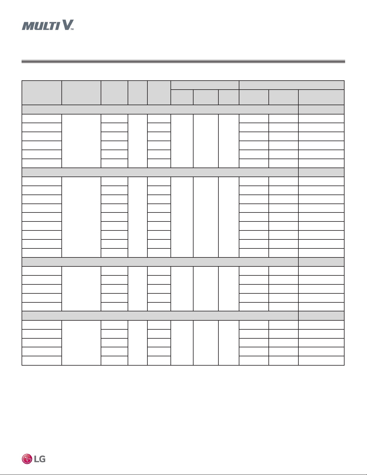
Table 6: Ducted High Static Indoor Unit Electrical Data.
Rated
Model Voltage Range MCA MOP
Amps
(A)
BH Units
ARNU073BHA4
ARNU093BHA4 1.32 1.06 150 150 52 / 58 / 67
ARNU123BHA4 1.32 1.06 150 150 58 / 67 / 78
ARNU153BHA4 1.32 1.06 150 150 58 / 78 / 90
ARNU183BHA4 1.32 1.06 150 150 78 / 90 / 103
ARNU243BHA4 1.32 1.06 150 150 103 / 117 / 132
208-230
1.32
1.06
15
M2 Units
ARNU073M2A4
ARNU093M2A4 2.9 2.3 430 430 21 / 29 / 38
ARNU123M2A4 2.9 2.3 430 430 25 / 34 / 43
ARNU153M2A4 2.9 2.3 430 430 25 / 34 / 43
ARNU183M2A4 2.9 2.3 430 430 34 / 43 / 67
ARNU243M2A4 2.9 2.3 430 430 34 / 43 / 67
ARNU283M2A4 2.9 2.3 430 430 57 / 88 / 123
ARNU363M2A4 2.9 2.3 430 430 88 / 123 / 184
ARNU423M2A4 2.9 2.3 430 430 136 / 193 / 231
208-230
2.9
2.3
15
M3 Units
ARNU283M3A4
ARNU363M3A4 3.1 2.5 650 650 75 / 107 / 161
ARNU423M3A4 3.1 2.5 650 650 75 / 107 / 161
ARNU483M3A4 3.1 2.5 650 650 75 / 107 / 172
ARNU543M3A4 3.1 2.5 650 650 172 / 215 / 260
208-230
3.1
2.5
15
B8 Units
ARNU363B8A4
ARNU423B8A4 6.5 5.2 800 800 465 / 497 / 528
ARNU483B8A4 6.5 5.2 800 800 482 / 500 / 538
ARNU763B8A4 6.5 5.2 800 800 505 / 505 / 765
ARNU963B8A4
208-230
6.5
15
6.5 5.2 800 800 750 / 750 / 800
5.2
Power Supply Power Input (W)
Hz Volts Phase
60 208-230 1
60 208-230 1
60 208-230 1
60 208-230 1
Max.
Cooling
150 150 49 / 52 / 58
430 430 21 / 29 / 38
650 650 60 / 83 / 109
800 800 403 / 420 / 478
Max.
Heating
L / M / H at
Factory Default
Ducted High Static
MCA : Minimum Circuit Ampacity.
MOP : Maximum Overcurrent Protection.
Units are suitable for use on an electrical system where voltage supplied to unit terminals is within the listed range limits.
Select wire size based on the larger MCA value.
Instead of fuse, use the circuit breaker.
Max. power input is rated at maximum setting value.
Due to our policy of continuous product innovation, some specications may change without notication.
© LG Electr onics U.S.A., Inc., Englewood Cl iffs, NJ. All r ights reserved. “LG” is a registered tra demark of LG Corp.
HIGH STATIC | 17
DUCTED HIGH STATIC
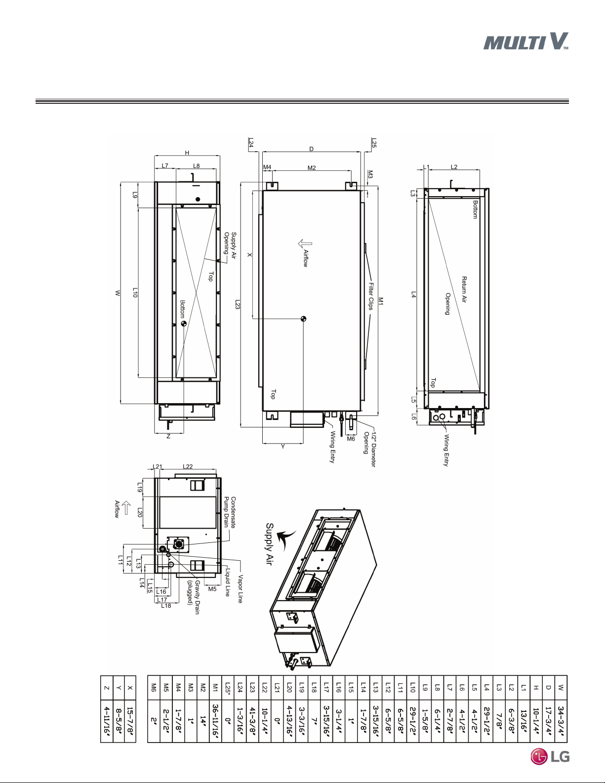
External Dimensions
BH Units
Figure 3: ARNU073~243BHA4 Dimensions.
MULTI V Ducted Indoor Unit Engineering Manual
Due to our policy of continuous product innovation, some specications may change without notication.
18 | HIGH STATIC
© LG Electr onics U.S.A., Inc., Englewood Cl iffs, NJ. All r ights reserved. “LG” is a registered tra demark of LG Corp.

Figure 4: ARNU073~423M2A4 Dimensions.
9-3/32
DUCTED HIGH STATIC
External Dimensions
M2 Units
47-1/2
10-11/16 16-9/16
49-3/16
27-1/16
47-15/32
9-5/16
10-11/16
1-25/32
26-5/32
27-9/16
Ducted High Static
27-1/4
7-7/8
54-7/32
49-9/32
24-3/8
50-17/32
3-9/16
7-7/32
6-19/32
5-15/32
2-1/32
7/8
27/32
8-21/32
10-13/32
9-1/4
14-9/32
Due to our policy of continuous product innovation, some specications may change without notication.
© LG Electr onics U.S.A., Inc., Englewood Cl iffs, NJ. All r ights reserved. “LG” is a registered tra demark of LG Corp.
HIGH STATIC | 19

DUCTED HIGH STATIC
External Dimensions
M3 Units
Figure 5: ARNU283~543M3A4 Dimensions.
12-21/32
12-3/4
14-27/32
47-9/16
49-3/16
27-1/8
47-19/32
12-27/32
14-3/16
2-1/32
11-7/16
26-3/16
27-19/32
49-1/4
27-3/16
24-3/8
50-9/16
54-11/32
7-3/8
2-7/32
1-3/32
13/16
6-27/32
5-1/2
MULTI V Ducted Indoor Unit Engineering Manual
6-5/32
7-15/16
6-3/4
12-23/32
28-9/16
Due to our policy of continuous product innovation, some specications may change without notication.
20 | HIGH STATIC
© LG Electr onics U.S.A., Inc., Englewood Cl iffs, NJ. All r ights reserved. “LG” is a registered tra demark of LG Corp.
3-5/8

Figure 6: ARNU363~963B8A4 Dimensions.
DUCTED HIGH STATIC
External Dimensions
B8 Units
Ducted High Static
Due to our policy of continuous product innovation, some specications may change without notication.
© LG Electr onics U.S.A., Inc., Englewood Cl iffs, NJ. All r ights reserved. “LG” is a registered tra demark of LG Corp.
HIGH STATIC | 21
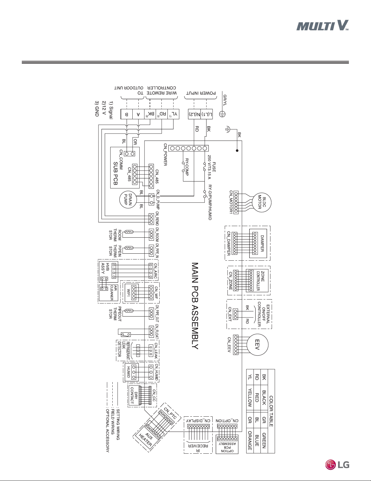
DUCTED HIGH STATIC
Electrical Wiring Diagram
BH Units
Figure 7: ARNU073~243BHA4 Wiring Diagram.
MULTI V Ducted Indoor Unit Engineering Manual
Due to our policy of continuous product innovation, some specications may change without notication.
22 | HIGH STATIC
© LG Electr onics U.S.A., Inc., Englewood Cl iffs, NJ. All r ights reserved. “LG” is a registered tra demark of LG Corp.

Table 7: BH Unit Wiring Diagram Legend.
Terminal Purpose Function
CN-POWER AC Power supply AC Power line
CN-MOTOR1 Fan motor output Motor output of BLDC
CN-DAMPER N / A N / A
CN-ZONE Zone controller Zone controller connection
CN-EXT External on / off controller External on / off Controller connection
CN-EEV EEV Output EEV control output
CN-OPTION Optional PCB EPROM Option PCB connection
CN-DISPLAY Display Display of indoor status
CN-PTC Auxiliary heater Connection for Auxiliary Heater
CN-CC Dry contact Dry Contact connection
CN-HUMID N / A N / A
CN-LEAK Leak detector Leak detector connection
CN-FLOAT Float switch input Float switch sensing
CN-PIPE/OUT Discharge pipe sensor Pipe out thermistor
CN-WF Wi-Fi Wi-Fi module connection
CN-AIRC N / A N / A
CN-PIPE/IN Suction pipe sensor Pipe in thermistor
CN-ROOM Room sensor Room air thermistor
CN-REMO Wired remote controller Wired remote control connection
CN-D/PUMP Drain pump output AC output for drain pump
CN-485 Communication Connection between indoor and outdoor units
DUCTED HIGH STATIC
Electrical Wiring Diagram
BH Units
Ducted High Static
Table 8: BH Unit DIP Switch Settings.
DIP Switch Setting Off On Remarks
SW3 GROUP CONTROL Master Slave
SW4
SW5 CONTINUOUS FAN Off On
*For Gen 4 Multi V ducted indoor units, DIP Switches 1, 2, 6 through 8 must be set to OFF. These DIP switches are used for
other models.
**To enable Generation 4 features, outdoor unit DIP Switch No. 3 must be set to ON. Please refer to the Multi V IV, Multi V Water IV, Multi V S Engineering Manual for additional information.
DRY CONTACT
MODE
Variable Auto
Due to our policy of continuous product innovation, some specications may change without notication.
© LG Electr onics U.S.A., Inc., Englewood Cl iffs, NJ. All r ights reserved. “LG” is a registered tra demark of LG Corp.
Group control setting using 7-Day Programmable Controller; selects Master /
Slave on each indoor unit
Sets operation mode for optional Dry Contact accessory
1. Variable: Auto or Manual Mode can be set through 7-Day Programmable
Controller or Wireless Remote Controller (factory default setting is Auto if
there is no setting)
2. Auto: For Dry Contact, it is always Auto mode
Selects continuous fan for ducted indoor units.
1. On: Indoor unit fan will always operate at a set fan speed, except when
the system is off, or the outdoor unit is in defrost mode (when the outdoor
unit is in defrost mode, the fan will operate at super low fan speed)
2. Off: Indoor unit fan speed can be changed by on / off
HIGH STATIC | 23

DUCTED HIGH STATIC
Electrical Wiring Diagram
M2 Units
Figure 8: ARNU073~423M2A4 Wiring Diagram.
MULTI V Ducted Indoor Unit Engineering Manual
Due to our policy of continuous product innovation, some specications may change without notication.
24 | HIGH STATIC
© LG Electr onics U.S.A., Inc., Englewood Cl iffs, NJ. All r ights reserved. “LG” is a registered tra demark of LG Corp.

Table 9: M2 Unit Wiring Diagram Legend.
Terminal Purpose Function
CN-POWER AC Power supply AC Power line
CN-MOTOR1 Fan motor output Motor output of BLDC
CN-VM Sub PCB to Main PCB power supply Power supply connection
CN-DAMPER N / A N / A
CN-ZONE Zone controller Zone controller connection
CN-EXT External on / off controller External on / off Controller connection
CN-EEV EEV Output EEV control output
CN-OPTION Optional PCB EPROM Option PCB connection
CN-DISPLAY Display Display of indoor status
CN-PTC Auxiliary heater Connection for Auxiliary Heater
CN-CC Dry contact Dry Contact connection
CN-HUMID N / A N / A
CN-LEAK Leak detector Leak detector connection
CN-FLOAT Float switch input Float switch sensing
CN-PIPE/OUT Discharge pipe sensor Pipe out thermistor
CN-WF Wi-Fi Wi-Fi module connection
CN-AIRC N / A N / A
CN-PIPE/IN Suction pipe sensor Pipe in thermistor
CN-ROOM Room sensor Room air thermistor
CN-REMO Wired remote controller Wired remote control connection
CN-D/PUMP Drain pump output AC output for drain pump
CN-485 Communication Connection between indoor and outdoor units
DUCTED HIGH STATIC
Electrical Wiring Diagram
M2 Units
Ducted High Static
Table 10: M2 Unit DIP Switch Settings.
DIP Switch Setting Off On Remarks
SW3 GROUP CONTROL Master Slave
SW4
SW5 CONTINUOUS FAN Off On
*For Gen 4 Multi V ducted indoor units, DIP Switches 1, 2, 6 through 8 must be set to OFF. These DIP switches are used for
other models.
**To enable Generation 4 features, outdoor unit DIP Switch No. 3 must be set to ON. Please refer to the Multi V IV, Multi V Water IV, Multi V S Engineering Manual for additional information.
DRY CONTACT
MODE
Variable Auto
Due to our policy of continuous product innovation, some specications may change without notication.
© LG Electr onics U.S.A., Inc., Englewood Cl iffs, NJ. All r ights reserved. “LG” is a registered tra demark of LG Corp.
Group control setting using 7-Day Programmable Controller; selects Master /
Slave on each indoor unit
Sets operation mode for optional Dry Contact accessory
1. Variable: Auto or Manual Mode can be set through 7-Day Programmable
Controller or Wireless Remote Controller (factory default setting is Auto if
there is no setting)
2. Auto: For Dry Contact, it is always Auto mode
Selects continuous fan for ducted indoor units.
1. On: Indoor unit fan will always operate at a set fan speed, except when
the system is off, or the outdoor unit is in defrost mode (when the outdoor
unit is in defrost mode, the fan will operate at super low fan speed)
2. Off: Indoor unit fan speed can be changed by on / off
HIGH STATIC | 25

DUCTED HIGH STATIC
Electrical Wiring Diagram
M3 Units
Figure 9: ARNU283~ARNU543M3A4 Wiring Diagram.
MULTI V Ducted Indoor Unit Engineering Manual
Due to our policy of continuous product innovation, some specications may change without notication.
26 | HIGH STATIC
© LG Electr onics U.S.A., Inc., Englewood Cl iffs, NJ. All r ights reserved. “LG” is a registered tra demark of LG Corp.
Table 11: M3 Unit Wiring Diagram Legend.
Terminal Purpose Function
CN-POWER AC Power supply AC Power line
CN-MOTOR1 Fan motor output Motor output of BLDC
CN-MOTOR2 Fan motor output Motor output of BLDC
CN-VM Sub PCB to Main PCB power supply Power supply connection
CN-DAMPER N / A N / A
CN-ZONE Zone controller Zone controller connection
CN-EXT External on / off controller External on / off Controller connection
CN-EEV EEV Output EEV control output
CN-OPTION Optional PCB EPROM Option PCB connection
CN-DISPLAY Display Display of indoor status
CN-PTC Auxiliary heater Connection for Auxiliary Heater
CN-CC Dry contact Dry Contact connection
CN-LEAK Leak detector Leak detector connection
CN-FLOAT Float switch input Float switch sensing
CN-PIPE/OUT Discharge pipe sensor Pipe out thermistor
CN-WF Wi-Fi Wi-Fi module connection
CN-HUMID N / A N / A
CN-AIRC N / A N / A
CN-PIPE/IN Suction pipe sensor Pipe in thermistor
CN-ROOM Room sensor Room air thermistor
CN-REMO Wired remote controller Wired remote control connection
CN-D/PUMP Drain pump output AC output for drain pump
CN-485 Communication Connection between indoor and outdoor units
DUCTED HIGH STATIC
Electrical Wiring Diagram
M3 Units
Ducted High Static
Table 12: M3 Unit DIP Switch Settings.
DIP Switch Setting Off On Remarks
SW3 GROUP CONTROL Master Slave
SW4
SW5 CONTINUOUS FAN Off On
*For Gen 4 Multi V ducted indoor units, DIP Switches 1, 2, 6 through 8 must be set to OFF. These DIP switches are used for
other models.
**To enable Generation 4 features, outdoor unit DIP Switch No. 3 must be set to ON. Please refer to the Multi V IV, Multi V Water IV, Multi V S Engineering Manual for additional information.
DRY CONTACT
MODE
Variable Auto
Due to our policy of continuous product innovation, some specications may change without notication.
© LG Electr onics U.S.A., Inc., Englewood Cl iffs, NJ. All r ights reserved. “LG” is a registered tra demark of LG Corp.
Group control setting using 7-Day Programmable Controller; selects Master /
Slave on each indoor unit
Sets operation mode for optional Dry Contact accessory
1. Variable: Auto or Manual Mode can be set through 7-Day Programmable
Controller or Wireless Remote Controller (factory default setting is Auto if
there is no setting)
2. Auto: For Dry Contact, it is always Auto mode
Selects continuous fan for ducted indoor units.
1. On: Indoor unit fan will always operate at a set fan speed, except when
the system is off, or the outdoor unit is in defrost mode (when the outdoor
unit is in defrost mode, the fan will operate at super low fan speed)
2. Off: Indoor unit fan speed can be changed by on / off
HIGH STATIC | 27

DUCTED HIGH STATIC
Electrical Wiring Diagram
B8 Units
Figure 10: ARNU363~963B8A4 Wiring Diagram.
MULTI V Ducted Indoor Unit Engineering Manual
Due to our policy of continuous product innovation, some specications may change without notication.
28 | HIGH STATIC
© LG Electr onics U.S.A., Inc., Englewood Cl iffs, NJ. All r ights reserved. “LG” is a registered tra demark of LG Corp.

Table 13: B8 Unit Wiring Diagram Legend.
Terminal Purpose Function
CN-POWER AC Power supply AC Power line
CN-MOTOR1 Fan motor output Motor output of BLDC
CN-MOTOR2 Fan motor output Motor output of BLDC
CN-VM Sub PCB to Main PCB power supply Power supply connection
CN-DAMPER N / A N / A
CN-ZONE Zone controller Zone controller connection
CN-EXT External on / off controller External on / off Controller connection
CN-EEV EEV Output EEV control output
CN-OPTION Optional PCB EPROM Option PCB connection
CN-DISPLAY Display Display of indoor status
CN-PTC Auxiliary heater Connection for Auxiliary Heater
CN-CC Dry contact Dry Contact connection
CN-LEAK Leak detector Leak detector connection
CN-FLOAT Float switch input Float switch sensing
CN-PIPE/OUT Discharge pipe sensor Pipe out thermistor
CN-WF Wi-Fi Wi-Fi module connection
CN-HUMID N / A N / A
CN-AIRC N / A N / A
CN-PIPE/IN Suction pipe sensor Pipe in thermistor
CN-ROOM Room sensor Room air thermistor
CN-REMO Wired remote controller Wired remote control connection
CN-D/PUMP Drain pump output AC output for drain pump
CN-485 Communication Connection between indoor and outdoor units
DUCTED HIGH STATIC
Electrical Wiring Diagram
B8 Units
Ducted High Static
Table 14: B8 Unit DIP Switch Settings.
DIP Switch Setting Off On Remarks
SW3 GROUP CONTROL Master Slave
SW4
SW5 CONTINUOUS FAN Off On
*For Gen 4 Multi V ducted indoor units, DIP Switches 1, 2, 6 through 8 must be set to OFF. These DIP switches are used for
other models.
**To enable Generation 4 features, outdoor unit DIP Switch No. 3 must be set to ON. Please refer to the Multi V IV, Multi V Water IV, Multi V S Engineering Manual for additional information.
DRY CONTACT
MODE
Variable Auto
Due to our policy of continuous product innovation, some specications may change without notication.
© LG Electr onics U.S.A., Inc., Englewood Cl iffs, NJ. All r ights reserved. “LG” is a registered tra demark of LG Corp.
Group control setting using 7-Day Programmable Controller; selects Master /
Slave on each indoor unit
Sets operation mode for optional Dry Contact accessory
1. Variable: Auto or Manual Mode can be set through 7-Day Programmable
Controller or Wireless Remote Controller (factory default setting is Auto if
there is no setting)
2. Auto: For Dry Contact, it is always Auto mode
Selects continuous fan for ducted indoor units.
1. On: Indoor unit fan will always operate at a set fan speed, except when
the system is off, or the outdoor unit is in defrost mode (when the outdoor
unit is in defrost mode, the fan will operate at super low fan speed)
2. Off: Indoor unit fan speed can be changed by on / off
HIGH STATIC | 29

DUCTED HIGH STATIC
Cooling
Refrigerant Flow Diagram
BH, M2, M3 Units
Figure 11: BH, M2, M3 Unit Refrigerant Flow Diagram.
Heat Exchanger
TH3
Sirocco Fan
TH1
Table 15: BH, M2, M3 Unit Refrigerant Pipe Connection Port Diameters.
Model Liquid (inch) Vapor (inch)
BH Units
ARNU073BHA4
ARNU093BHA4
ARNU123BHA4
ARNU153BHA4
ARNU183BHA4
ARNU243BHA4 3/8 Flare 5/8 Flare
M2 Units
ARNU073M2A4 1/4 Flare 1/2 Flare
ARNU093M2A4 1/4 Flare 1/2 Flare
ARNU123M2A4
MULTI V Ducted Indoor Unit Engineering Manual
M3 Units
ARNU153M2A4 1/4 Flare 1/2 Flare
ARNU183M2A4 1/4 Flare 1/2 Flare
ARNU243M2A4 3/8 Flare 5/8 Flare
ARNU283M2A4 3/8 Flare 5/8 Flare
ARNU363M2A4 3/8 Flare 5/8 Flare
ARNU423M2A4 3/8 Flare 5/8 Flare
ARNU283M3A4
ARNU363M3A4
ARNU423M3A4
ARNU483M3A4
ARNU543M3A4
1/4 Flare 1/2 Flare
1/4 Flare 1/2 Flare
3/8 Flare 5/8 Flare
TH2
lndoor unit
EEV
Heating
Filter
Filter
Table 16: BH, M2, M3 Frame Thermistors.
Thermistor Description
TH1 Return air thermistor
TH2 Pipe in thermistor
TH3 Pipe out thermistor
30 | HIGH STATIC
Due to our policy of continuous product innovation, some specications may change without notication.
© LG Electr onics U.S.A., Inc., Englewood Cl iffs, NJ. All r ights reserved. “LG” is a registered tra demark of LG Corp.
 Loading...