

LG 47LY3RF Owner’s Manual
Please read this manual carefully before operating
your set.
Retain it for future reference.
Record model number and serial number of the set.
Refer to the label on the back cover and quote this
information.
To your dealer when requiring service.
LCD TV
PLASMA TV
OWNER’S MANUAL
LCD TV MODELS
4422LLBB77RR FF
**
4477LLBB77RR FF
**
4477LLYY33RR FF
**
5522LLBB99RR FF
**
4477 LLBB99 RR
**
PLASMA TV MODELS
6600PPYY33 RRFF
**
6600 PPCC44RR
**
ONLY 42LB7RF
*
47LB7RF
*
47LY3RF
*
52LB9RF
*
60PY3RF
*

1
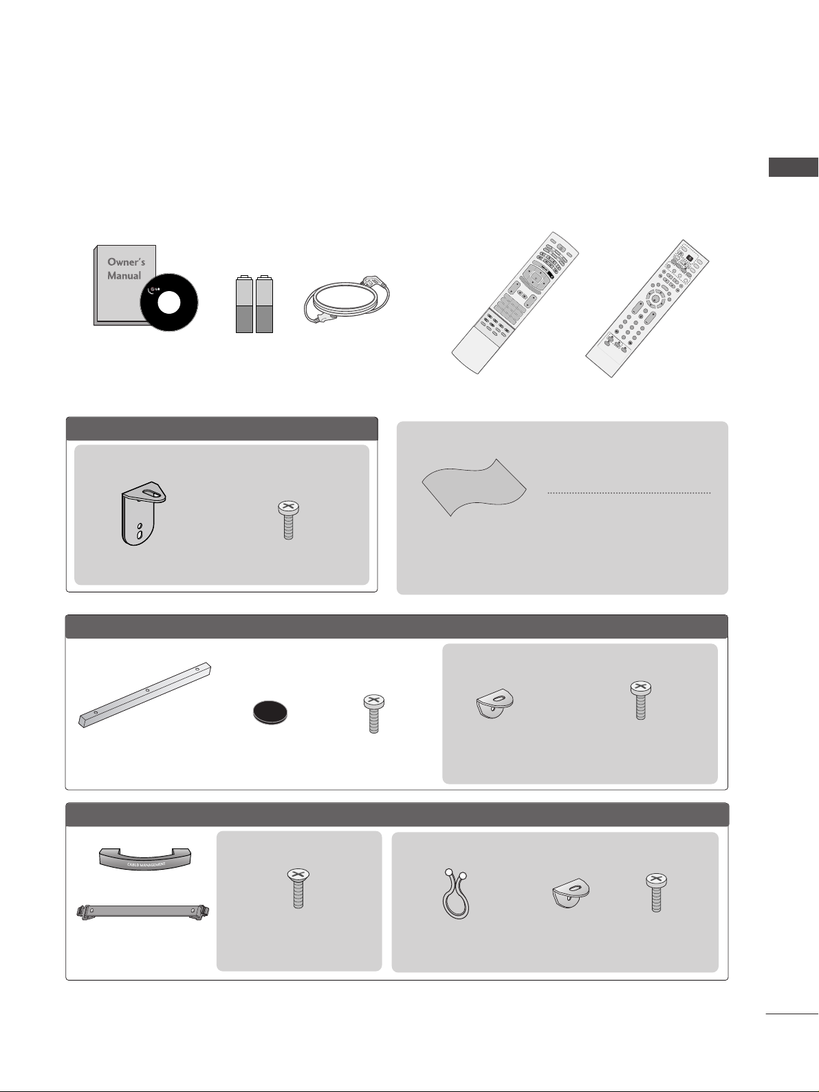
ACCESSORIES
Ensure that the following accessories are included with your TV. If an accessory is missing, please contact the
dealer where you purchased the product.
ACCESSORIES
Owner’s Manual Batteries
TV
IN
P
U
T
VOL
LIST
Q
.
V
I
E
W
P
R
P
O
W
E
R
1 2 3
456
78
0
9
POSITION
S
I
Z
E
H
O
L
D
A
U
D
I
O
M
E
N
U
MUTE
E
X
IT
V
C
R
T
V
D
V
D
C
A
B
L
E
T
IM
E
R
E
V
E
A
L
?
i
O
K
M
O
D
E
S
T
B
P
IP
P
R
-
P
IP
P
R
+
SW
A
P
P
IP
I
NP
U
T
TEXT
I
N
D
E
X
S
L
E
E
P
F
A
V
P
IP
R
A
T
I
O
I
/
I
I
Remote Control
Power Cord
Twister Holder
Arrange the wires with the
twister holder.
LLCCDD TTVV mmooddeellss
FFoorr 6600PPYY33RRFF** mmooddeellss
Polishing Cloth
Polishing cloth for use on the
screen
*
Lightly wipe any stains or fingerprints on the surface of the TV with
the polishing cloth.
Do not use excessive force. This may
cause scratching or discolouration.
Cable Management
OK
IN
P
U
T
M
O
D
E
T
V
T
V
D
V
D
RATIO
E
X
IT
V
O
L
P
O
S
IT
IO
N
INDEX
P
R
P
I
P
S
L
E
E
P
L
I
S
T
Q
.
V
I
E
W
I/II
M
E
N
U
S
IZE
V
C
R
PIP PR- PIP PR+
P
I
P
I
N
P
U
T
P
O
W
E
R
123
456
789
0
F
A
V
R
E
V
E
A
L
?
T
E
X
T
SIM
PLIN
K
I
N
P
U
T
M
U
T
E
T
IM
E
H
O
L
D
OK
IN
P
U
T
T
V
RATIO
E
X
IT
V
O
L
P
O
S
IT
IO
N
INDEX
P
R
P
IP
S
L
E
E
P
L
I
S
T
Q
.
V
I
E
W
I/
II
M
E
N
U
S
IZ
E
PIP PR- PIP PR+
P
IP
IN
P
U
T
P
O
123
456
789
0
F
A
V
R
E
V
E
A
L
?
T
E
X
T
SIMP
LINK
I
N
P
U
T
M
U
T
E
TIM
E
H
O
LD
S
W
A
P
S
W
A
P
or
4-bolts for stand assembly
See below for detail information.
(Refer to p.8)
2-Rubber cap
Refer to p. 13
3-bolts
Refer to p. 14
Desk-type stand
fixture protection cover
Refer to p. 14
2- TV Brackets
2- Wall Brackets
2- TV Bracket Bolts
2- Wall brackets
2- TV brackets
FFoorr 6600PPCC44RR** mmooddeellss
2- TV Bracket Bolts
This feature is not available for all models.
This feature is not available for all models.
2- TV Brackets
2- Wall Brackets
2- TV Bracket Bolts
This feature is not available for all models.
Except 47LB9R*, 52LB9RF*
or
2
CONTENTS
CONTENTS
PICTURE CONTROL
Watching PIP(Picture-in-Picture) .............................52
Picture Size (Aspect Ratio)Control.........................54
Preset Picture Settings
- Picture Mode-Preset............................................56
- Auto Colour Tone Control(Warm/Medium/Cool)
57
Manual Picture Adjustment
- Picture Mode-User Option................................58
- Colour Tone - User Option...............................59
-
Picture Improvement Technology
...................60
Advanced - Cinema......................................................61
Advanced - TruMotion ................................................61
Advanced - Black(Darkness) Level...........................62
Picture Reset..................................................................63
Demo .................................................................64
TruMotion Demo ..........................................................64
Image Sticking Minimization(ISM) Method ..........65
Low-Power Picture Mode............................................66
Index.................................................................................67
WATCHING TV /PROGRAMME CONTROL
Remote Control Key Functions.................................34
Turning on the TV....................................................... 38
Programme Selection ................................................. 38
Volume Adjustment......................................................38
On Screen Menus Selection and Adjustment ......39
Auto Programme Tuning............................................ 40
Manual Programme Tuning........................................ 41
Fine Tuning .....................................................................42
Assigning a Station Name ..........................................43
Booster............................................................................44
Programme Edit ........................................................... 45
Favourite Programme .................................................. 46
Calling the Programme List....................................... 47
Input Source Selection ...............................................48
................................................................. 49
Key lock.......................................................................... 51
PICTURE CONTROL
WATCHING TV / PROGRAMME CONTROL
AACCCCEESSSSOORRIIEESS
.....................................................1
PREPARATION
Front Panel Controls..................................................... 4
Back Panel Information ................................................ 6
Stand Installation........................................................... 8
Swivel Stand ................................................................... 9
Attaching the TV to a Wall .........................................10
Back Cover for Wire Arrangement........................... 11
Desktop Pedestal Installation ................................... 13
Wall Mount: Horizontal installation........................ 14
Antenna Connection................................................... 15
EXTERNAL EQUIPMENT SETUP
HD Receiver Setup .......................................................16
DVD Setup..................................................................... 19
VCR Setup..................................................................... 22
Other A/V Source Setup .......................................... 25
PC Setup.........................................................................26
- Screen Setup for PC Mode ...............................29
AV Output Setup ........................................................ 33
External Stereo Setup ................................................ 33
PREPARATION

3
CONTENTS
SOUND & LANGUAGE CONTROL
Preset Sound Settings - Sound Mode ....................68
Sound Setting Adjustment - User Mode ...............69
Auto Volume Leveler....................................................70
Balance ............................................................................71
TV Speakers On/Off Setup .......................................72
I/II
- Stereo/Dual Reception.......................................73
- NICAM Reception ................................................74
- Speaker Sound Output Selection....................74
On-Screen Menu Language Selection
...................... 75
APPENDIX
Troubleshooting............................................................83
Maintenance .................................................................85
Product Specifications ................................................86
Programming the Remote Control ........................ 88
IR Codes..........................................................................91
External Control Through RS-232C .......................94
TIME SETTING
Clock Setting..................................................................76
Auto On/Off Timer Setting .......................................77
Sleep Timer Setting......................................................78
Auto Shut-off Setting ..................................................79
TELETEXT
Switch On/Off .............................................................80
SIMPLE Text ...................................................................80
TOP Text..........................................................................81
FASTEXT..........................................................................81
Special Teletext Functions..........................................82
4
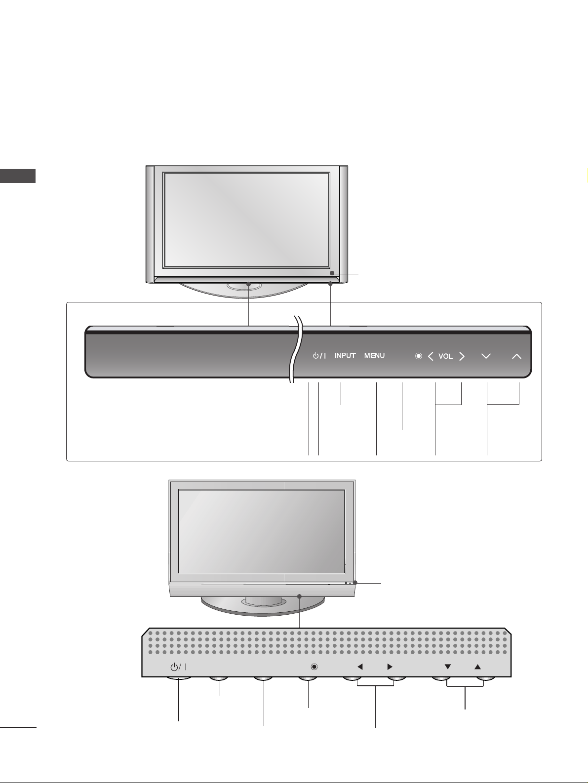
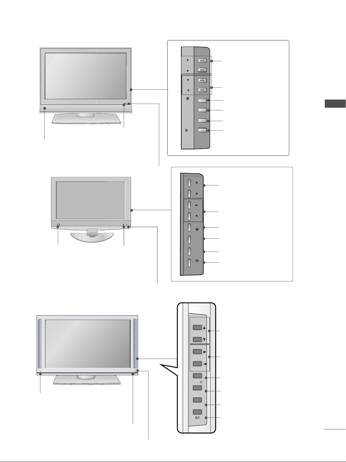
FRONT PANEL CONTROLS
PREPARATION
PREPARATION
■
This is a simplified representation of the front panel. Image shown may differ from your TV.
■
If your product has a protection film attached, remove the film and then wipe the product with a polishing
cloth.
Remote Control Sensor
60PY3RF
*
Remote Control Sensor
PROGRAMME Buttons
VOLUME Buttons
MENU Button
OK Button
INPUT Button
POWER Button
PR
VOL
OK
MENU
INPUT
60PC4R
*
VOLUME
(
FF,GG
)
Buttons
PROGRAMME
(
EE,DD
)
Buttons
OK
Button
MENU
Button
INPUT
Button
POWER
Button
Power Standby Indicator
• illuminates red in standby
mode.
OK
PR
OK
PR
5
PREPARATION
42/47LB7RF
*
R
Remote Control Sensor
Power/Standby Indicator
• illuminates red in standby mode.
• illuminates green when the set is
switched on.
PROGRAMME Buttons
VOLUME Buttons
OK Button
MENU Button
INPUT Button
POWER Button
Remote Control Sensor
Power/Standby Indicator
• illuminates red in standby mode.
• illuminates green when the set is switched on.
PROGRAMME Buttons
VOLUME Buttons
OK Button
MENU Button
INPUT Button
POWER Button
47LY3RF
*
Intelligent Eye
Intelligent Eye
47LB9R*, 52LB9RF
*
PR
VOL
OK
MENU
INPUT
/I
Remote Control Sensor
Intelligent Eye
Power/Standby Indicator
• illuminates red in standby mode.
• illuminates green when the set is switched on.
PROGRAMME Buttons
VOLUME Buttons
OK Button
MENU Button
INPUT Button
POWER Button
PR
VOL
OK
MENU
INPUT
/I
PR
VOL
OK
MENU
INPUT
6
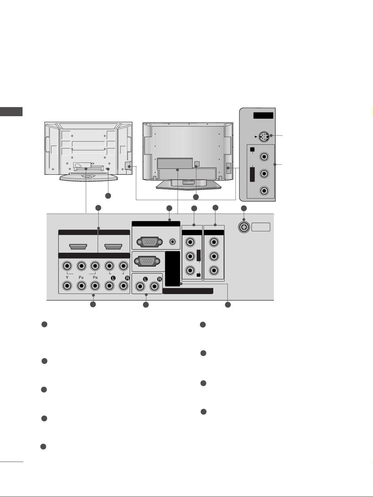
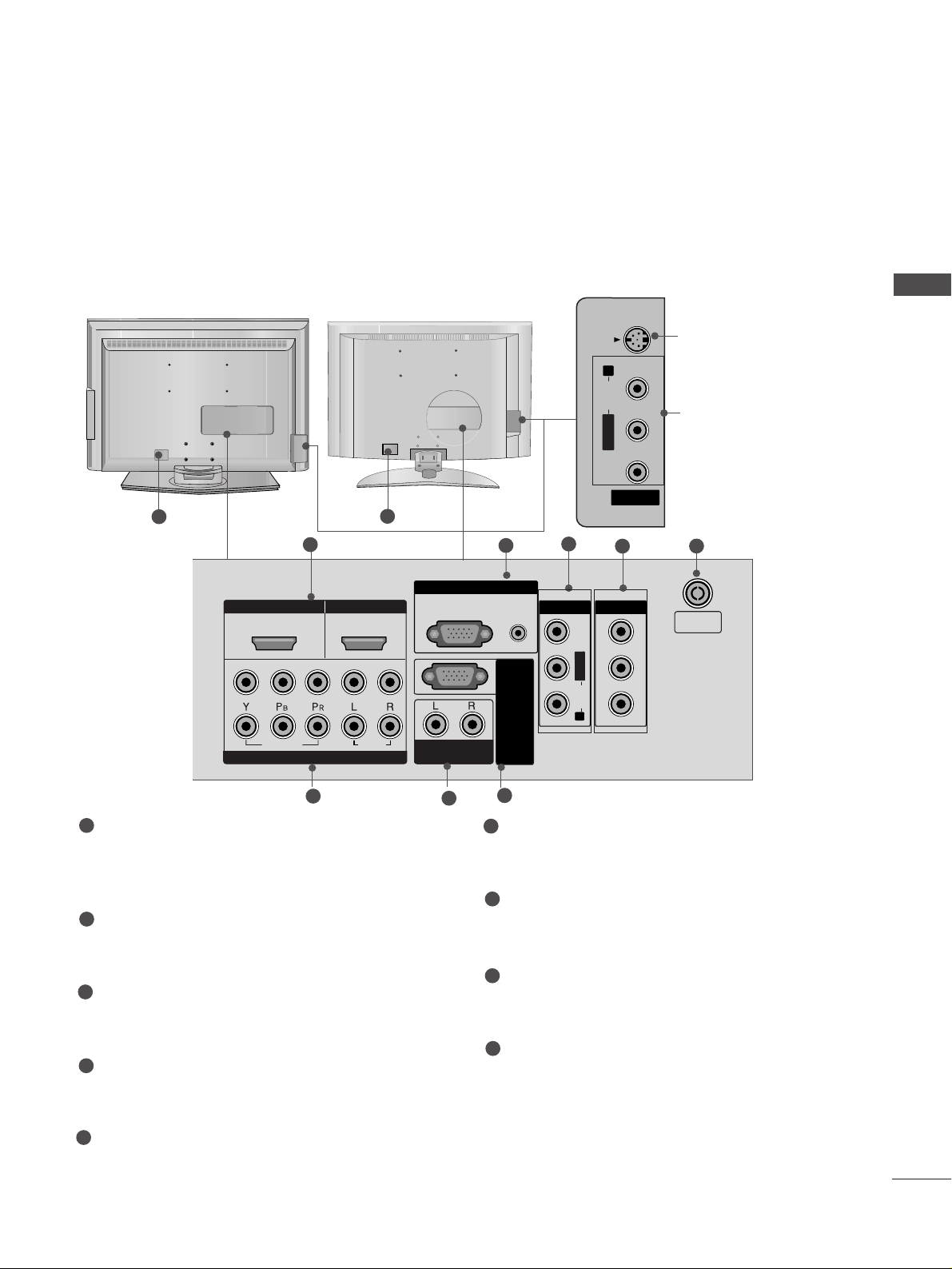
BACK PANEL INFORMATION
PREPARATION
PREPARATION
■
This is a simplified representation of the back panel. Image shown may differ from your TV.
AV IN 2
L/ MONO
R
AUDIO
VIDEO
S-VIDEO
HDMI IN HDMI IN HDMI/DVI IN HDMI/DVI IN
1
1
2
2
VARIABLE ARIABLE AUDIO OUTAUDIO OUT
AUDIO
(RGB/DVI)
RGB
(PC)
RGB INRGB IN
COMPONENT INCOMPONENT IN
AUDIO
VIDEO
AV IN 1V IN 1 AV OUTV OUT
L/L/MONOMONO
R
AUDIOAUDIO
VIDEOVIDEO
ANTENNA
IN
RS-232C IN
(CONTROL&SERVICE)
2
1
4
3
5
7 8
6
HDMI/DVI1, HDMI2 Input
Connect a HDMI signal to HDMI IN.
Or DVI(VIDEO)signal to HDMI/DVI port with DVI
to HDMI cable.
RGB/Audio Input
Connect the monitor output from a PC to the
appropriate input port.
Audio/Video Input (AV IN 1)
Connect audio/video output from an external
device to these jacks.
AV Output
Connect second TV or monitor to the AV OUT
socket on the set.
Antenna Input
Connect RF antenna (UHF) to this jack.
Component Input 1/2
Connect a component video/audio device to
these jacks.
Variable Audio Output
Connect an external amplifier or add a subwoofer
to your surround sound system.
RS-232C Input
(CONTROL&SERVICE)Port
Connect the serial port of the control devices
to the RS-232C jack.
Power Cord Socket
This TV operates on an AC power. The voltage is
indicated on the Specifications page. Never
attempt to operate the TV on DC power.
1
2
3
4
5
6
7
8
9
9
AV IN 3
L/MONO
R
AUDIO
VIDEO
S-VIDEO
S-Video Input
Connect S-Video out
from an S-VIDEO device.
Audio/Video Input
Connect audio/video
output from an external
device to these jacks.
AV IN 2V IN 2
L/L/MONOMONO
R
AUDIOAUDIO
VIDEOVIDEO
S-VIDEOS-VIDEO
9
Plasma TV Models
AV IN 2
L/MONO
R
AUDIO
VIDEO
USB IN
AV IN 2
L/MONO
R
AUDIO
VIDEO
S-VIDEO
7
PREPARATION
LCD TV Models
8
S-Video Input
Connect S-Video out
from an S-VIDEO device.
Audio/Video Input
Connect audio/video
output from an external
device to these jacks.
AV IN 2
L/MONO
R
AUDIOAUDIO
VIDEOVIDEO
S-VIDEOS-VIDEO
AV IN 2
L/ MONO
R
AUDIO
VIDEO
S-VIDEO
HDMI IN
HDMI/DVI IN
ARIABLE
AUDIO OUT
COMPONENT IN
V IN 1
V OUT
RGB IN
(CONTROL&SER
L/
MONO
AUDIO
VIDEO
L/ MONO
R
AUDIO
VIDEO
2
1
4
3
5
7
6
9
HDMI/DVI1, HDMI2 Input
Connect a HDMI signal to HDMI IN.
Or DVI(VIDEO)signal to HDMI/DVI port with DVI
to HDMI cable.
RGB/Audio Input
Connect the monitor output from a PC to the
appropriate input port.
Audio/Video Input (AV IN 1)
Connect audio/video output from an external
device to these jacks.
AV Output
Connect second TV or monitor to the AV OUT
socket on the set.
Antenna Input
Connect RF antenna (UHF) to this jack.
Component Input 1/2
Connect a component video/audio device to
these jacks.
Variable Audio Output
Connect an external amplifier or add a subwoofer
to your surround sound system.
RS-232C Input
(CONTROL&SERVICE)Port
Connect the serial port of the control devices
to the RS-232C jack.
Power Cord Socket
This TV operates on an AC power. The voltage is
indicated on the Specifications page. Never
attempt to operate the TV on DC power.
1
2
3
4
5
6
7
8
9
9
HDMI/DVI IN
1
1
2
VIDEO
COMPONENT IN
HDMI IN
2
AUDIO
RGB IN
RGB(PC)
VARIABLE
AUDIO OUT
AUDIO
(RGB/DVI)
RS-232C IN
AV IN 1
VICE)
NTROL&SER
(CO
AV OUT
VIDEO
MONO
L/
AUDIO
R
ANTENNA
IN
8
PREPARATION
PREPARATION
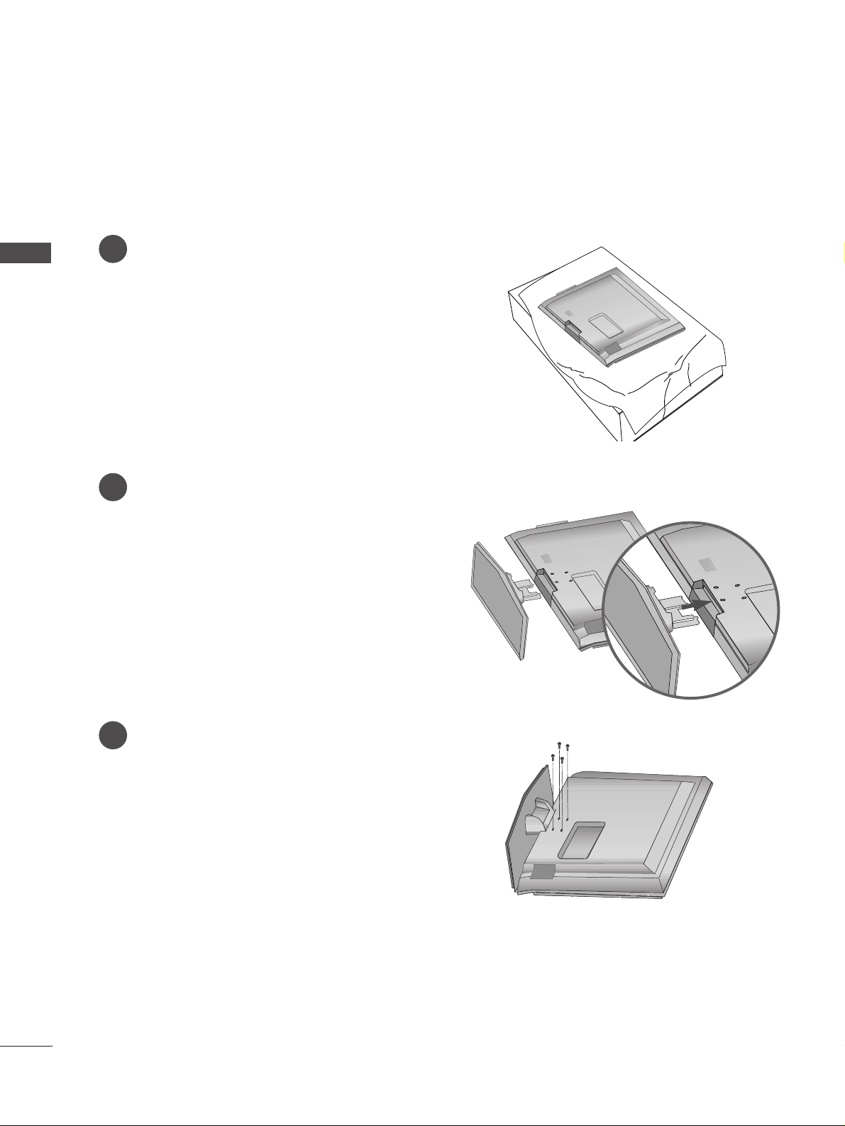
STAND INSTALLATION
(42/47LB7RF* only)
1
2
3
Carefully place the product screen side down on
a cushioned surface to protect the screen from
damage.
Assemble the product as shown.
Fix the 4 bolts securely using the holes in the
back of the product.
9
PREPARATION
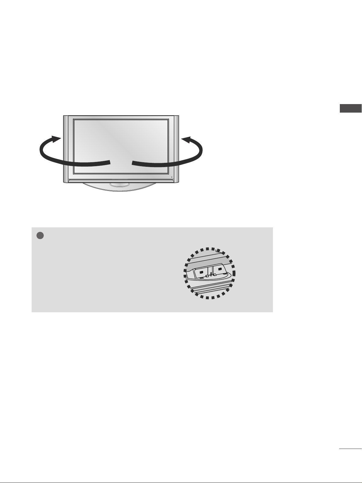
SWIVEL STAND
(60PY3RF* only)
After installing the TV, you can adjust the TV set manually to the left or right direction by 20 degrees to suit
your viewing position.
NOTE
!
GG
Before adjusting the angle, you must
remove the cable management and loosen
(to the left) the shaft bolt on the middle of
stand’s back. And when stand be level with
TV, you must close (to the right) the shaft
bolt to set the hole.
10
PREPARATION
PREPARATION
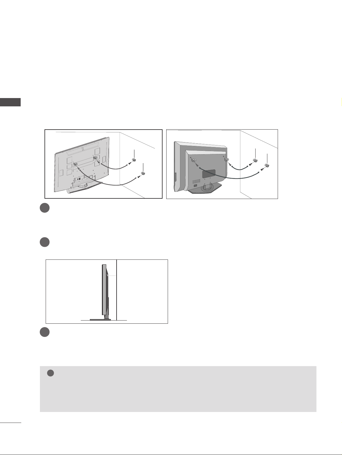
ATTACHING THE TV TO A WALL
Plasma TV models
LCD TV models
2
1
A
This feature is not available for all models.
A
Position the TV close to the wall to avoid the possibility of it falling when pushed.
A
The instructions shown below are a safer way to set up the TV, which is to fix it to the wall, avoiding the
possibility of it falling forwards if pulled. This will prevent the TV from falling forward and causing injury.
This will also prevent the TV from damage. Ensure that children do not climb or hang from the TV.
NOTE
!
G
When moving the TV undo the cords first.
G
Use a platform or cabinet string and large enough to support the size and weight of the TV.
G
To use the TV safely make sure that the height of the bracket on the wall and on the TV is the same.
2
3
1
1
2
Use the eye-bolts or TV brackets/bolts to fix the product to the wall as shown in the picture.
(If your TV has bolts in the eyebolts, loosen then bolts.)
* Insert the eye-bolts or TV brackets/bolts and tighten them securely in the upper holes.
Secure the wall brackets with bolts (must purchase seperately) to the wall.
Ensure that both brackets are even.
3
Use a strong cord (must purchase separately) to secure the TV.
Secure the cord in such a way that it becomes taught when the TV is in position.
11
PREPARATION
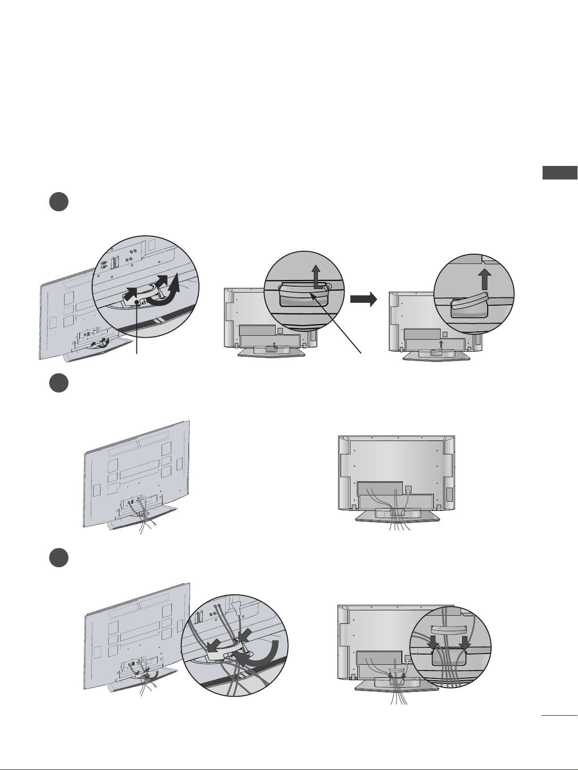
BACK COVER FOR WIRE ARRANGEMENT
Plasma TV models
2
1
3
Grip the CABLE MANAGEMENT and push the cover upwards.
Connect the cables as necessary.
To connect additional equipment, see the External equipment Setup section of the manual.
Install the CABLE MANAGEMENT as shown.
CABLE MANAGEMENT
45
°
CABLE MANAGEMENT
12
PREPARATION
PREPARATION
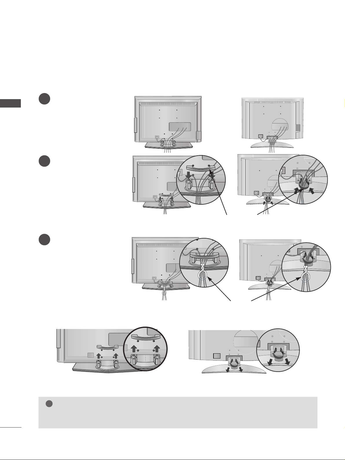
LCD TV models
Connect the cables as necessary.
To connect additional equipment, see the
EExxtteerrnnaall
eeqquuiippmmeenntt CCoonnnneeccttiioonnss
section.
1
Install the
CC AABBLLEE MMAA NN--
AAGG EEMMEENNTT
as shown.
2
Bundle the cables using the
supplied twister holder.
(
This feature is not available
for all models.)
3
Hold the
CC AABBLLEE MM AANNAAGGEE MMEE NNTT
with both hands and pull it upward.
NOTE
!
GG
Do not use the CABLE MANAGEMENT to lift the TV.
- If the TV is dropped, you may be injured or the TV may be damaged.
How to remove the cable management
CABLE MANAGEMENT
TWIST HOLDER
or
or
or
or
(Insert it as pushing the loops on the
both sides of the cable management.)
(Pull it out as holding the loops on the both
sides of the cable management.)
13
PREPARATION
■
The TV can be installed in various ways such as on a wall, or on a desktop etc.
■
The TV is designed to be mounted horizontally.
Power Supply
Circuit breaker
EARTHING
Ensure that you connect the earth wire to prevent possible
electric shock. If grounding methods are not possible, have a
qualified electrician install a separate circuit breaker.
Do not try to earth the TV by connecting it to telephone
wires, lightening rods or gas pipes.
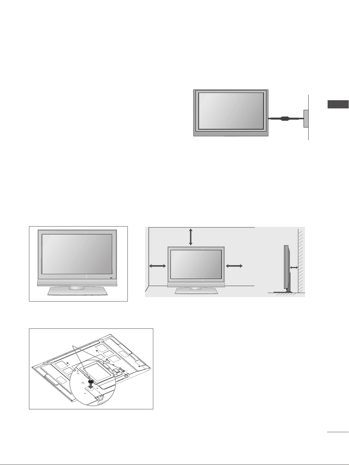
DESKTOP PEDESTAL INSTALLATION
For adequate ventilation allow a clearance of 4” (10cm) all around the TV .
When not using the desk-type stand (60PY3RF* only)
When not using the desk-type stand,
install the supplied rubber caps for
protecting the desk-type stand fixture
as shown at the figure.
4 inches
4 inches
4 inches
4 inches
Rubber cap
R
14
PREPARATION
PREPARATION
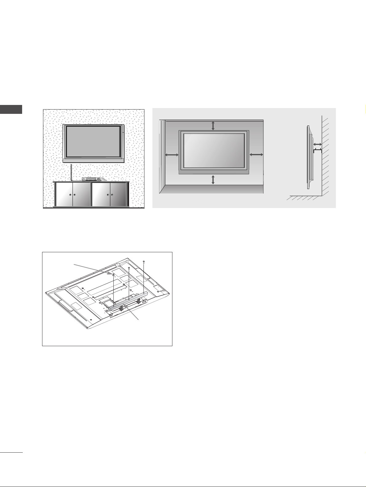
WALL MOUNT: HORIZONTAL INSTALLATION
For adequate ventilation allow a clearance of 4” (10cm) all around the TV. Detailed installation instruc-tions
are available from your dealer, see the optional Tilt Wall Mounting Bracket Installation and Setup Guide.
4 inches
4 inches
4 inches
4 inches
4 inches
If you want to install the desk-type stand fixture protection cover (60PY3RF* only)
To prevent the foreign materials from
entering the desk-type stand fixture, fix
the desk-type stand fixture protection
cover by using the supplied bolts as
shown at the figure.
Bolts
Desk-type stand
fixture protection
cover
15
PREPARATION
AV IN 3
L/MONO
R
AUDIO
VIDEO
S-VIDEO
AV IN 2
L/ MONO
R
AUDIO
VIDEO
S-VIDEO
AV IN 2
L/ MONO
R
AUDIO
VIDEO
S-VIDEO
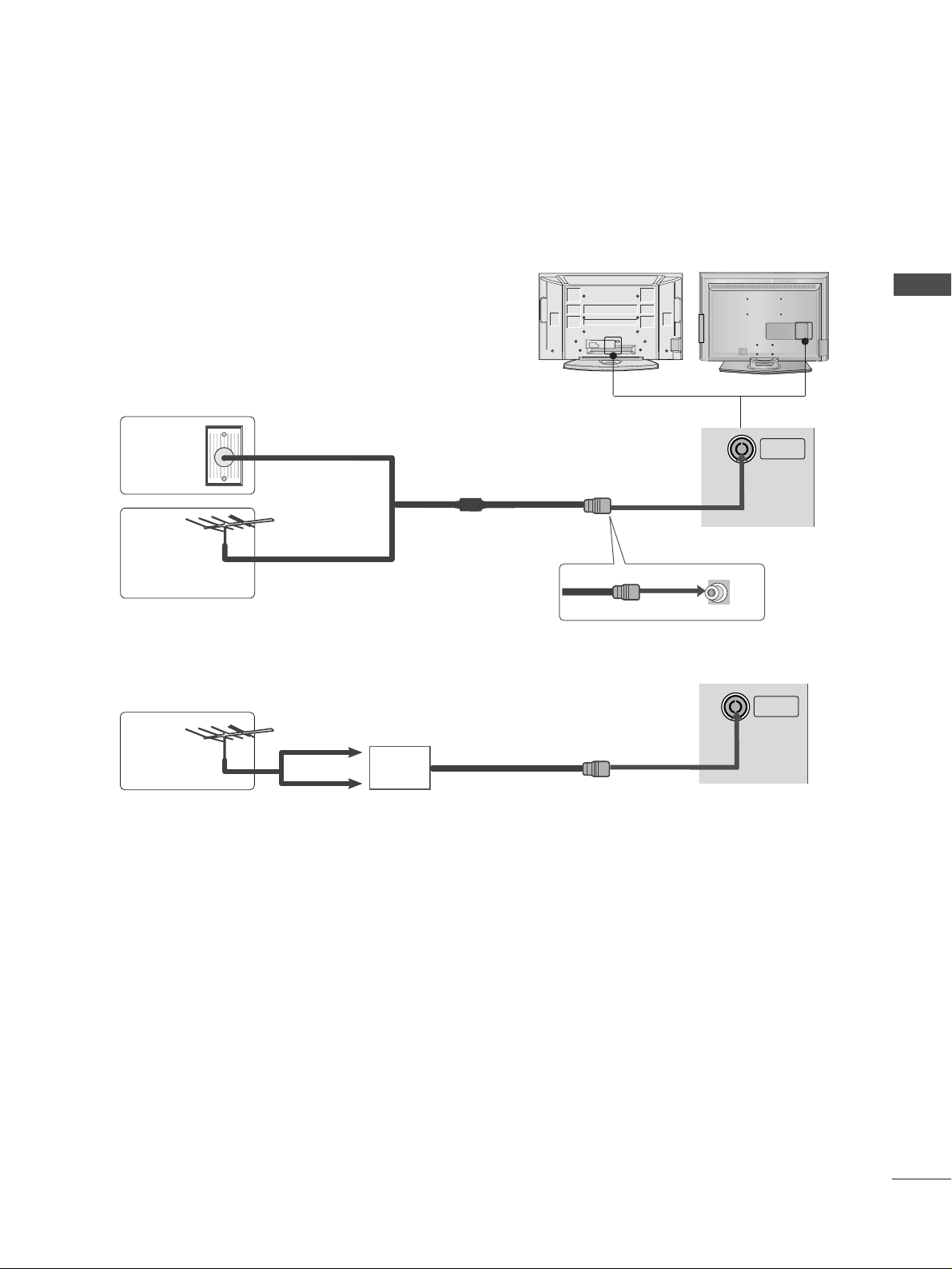
ANTENNA CONNECTION
■
For optimum picture quality, adjust antenna direction.
■
An antenna cable and converter are not supplied.
Multi-family Dwellings/Apartments
(Connect to wall antenna socket)
Single-family Dwellings /Houses
(Connect to wall jack for outdoor antenna)
Outdoor
Antenna
Wall
Antenna
Socket
RF Coaxial Wire (75 ohm)
Antenna
UHF
Signal
Amplifier
VHF
■
In poor signal areas, to achieve better picture quality it may be necessary to install a signal amplifier to the
antenna as shown above.
■
If signal needs to be split for two TVs,use an antenna signal splitter for connection.
■
To prevent damage do not connect to the mains outlet until all connections are made between the devices.
ANTENNA
IN
ANTENNA
IN
16
EXTERNAL EQUIPMENT SETUP
HDMI IN HDMI DVI IN
1
2
COMPONENT INCOMPONENT IN
AUDIO
VIDEO
HDMI IN HDMI DVI IN
HDMI/DVI IN
1
1 2
EXTERNAL EQUIPMENT SETUP
HD RECEIVER SETUP
When connecting with a component cable
Connect the video outputs (Y, PB
, PR
)
of the digital set
top box to the
CC OOMMPPOONNEENN TT IINN VV II DDEEOO
jacks on the
set.
Connect the audio output of the digital set-top box to
the
CC OOMMPPOONNEENN TT IINN AAUUDDIIOO
jacks on the set.
Turn on the digital set-top box.
(
Refer to the owner’s manual for the digital set-top box.
)
Select
Component1 input source using the
II NNPPUUTT
button on the remote control.
If connected to
CC OOMMPPOONNEENN TT IINN22
, select
Component2 input source.
2
3
4
1
Signal
480i/576i
480p/576p
720p
10 8 0 i
1080p(50Hz/60Hz)
Component 1/2
Yes
Yes
Yes
Yes
Yes
HDMI1/DVI, HDMI2
No
Yes
Yes
Yes
Yes
■
To avoid damaging any equipment, never plug in any power cords until you have finished connecting all equipment.
■
This section on EXTERNAL EQUIPMENT SETUP mainly uses diagrams for the Plasma TV models.
17
EXTERNAL EQUIPMENT SETUP
HDMI-DTV OUTPUT
HDMI IN HDMI DVI IN
1
2
COMPONENT IN
HDMI IN HDMI DVI IN
HDMI/DVI IN
1
HDMI IN HDMI DVI IN
HDMI IN HDMI IN HDMI/DVI IN HDMI/DVI IN
1 2
1
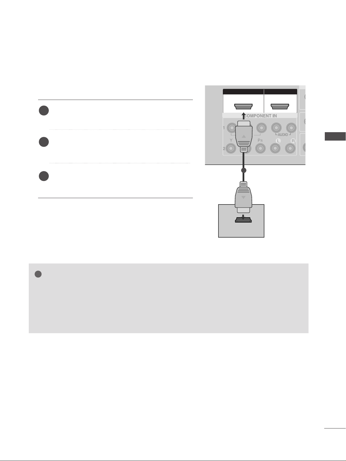
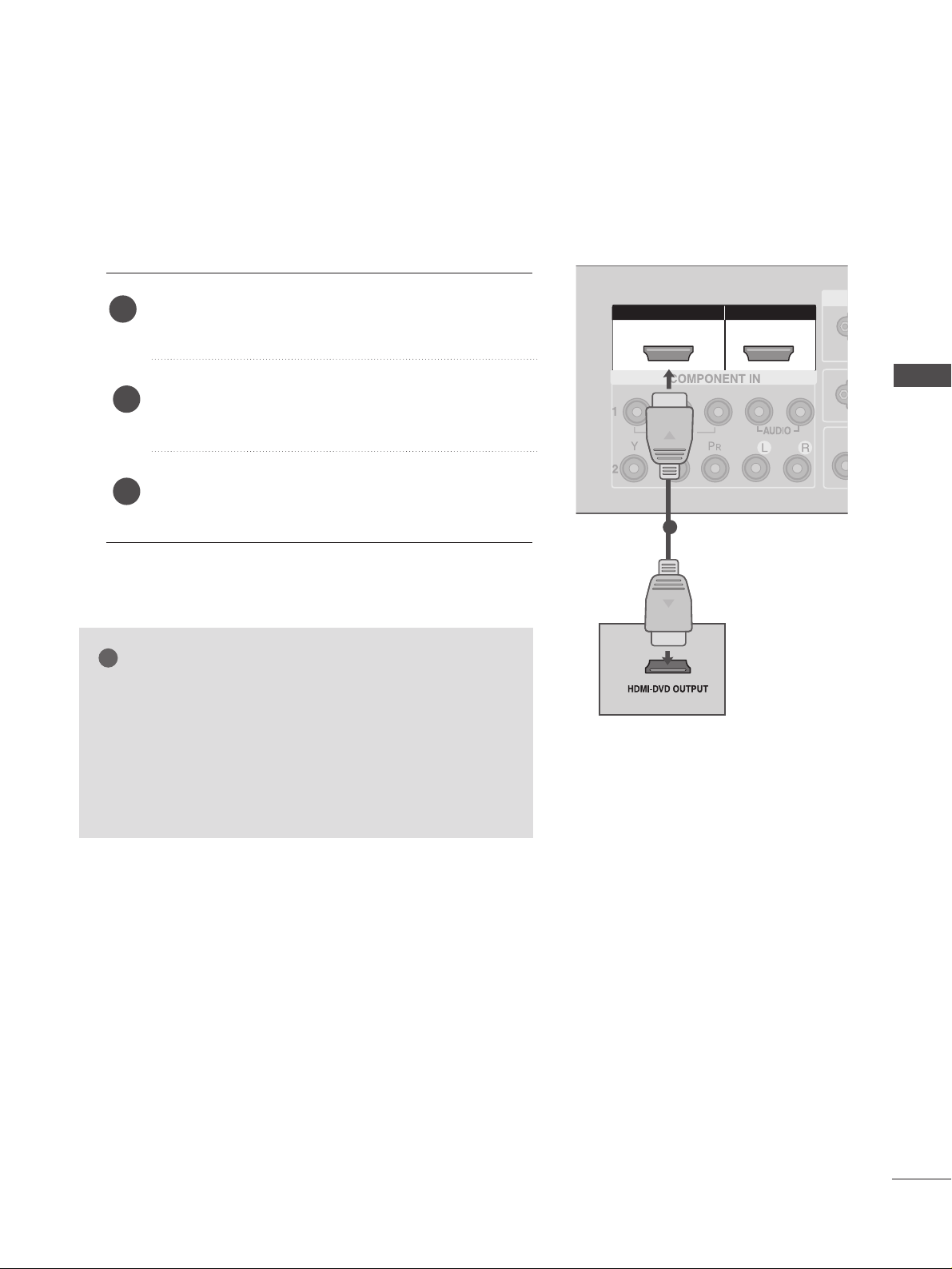
When connecting with a HDMI cable
Connect the HDMI output of the digital set-top box to
the
HHDD MMII//DD VVII IINN 11
or
HHDDMM II IINN 22
jack on the set.
Select
HDMI1/DVI or HDMI2 input source using the
II NNPPUUTT
button on the remote control.
Turn on the digital set-top box.
(
Refer to the owner’s manual for the digital set-top box.
)
2
3
1
GG
If the digital set-top box supports Auto HDMI function, the output resolution of the source device will
be automatically set to 1280x720p.
GG
If the digital set-top box player does not support Auto HDMI, you need to set the output resolution
appropriately.
To get the best picture quality, adjust the output resolution of the source device to 1920x1080i/1080p.
(60PC4R*,47LB9R* : 1280x720p)
NOTE
!
18
EXTERNAL EQUIPMENT SETUP
EXTERNAL EQUIPMENT SETUP
AUDIO
(RGB/DVI)
RGB
(PC)
HDMI IN HDMI DVI IN
AUDIO
(RGB/DVI)
RGB
(PC)
RGB INRGB IN
HDMI/DVI IN HDMI/DVI IN
1
RS-232C
(CONTROL&SERVICE)
AV IN 1AV IN 1 AV OUTAV OUT
L/MONO
AUDIO OUT
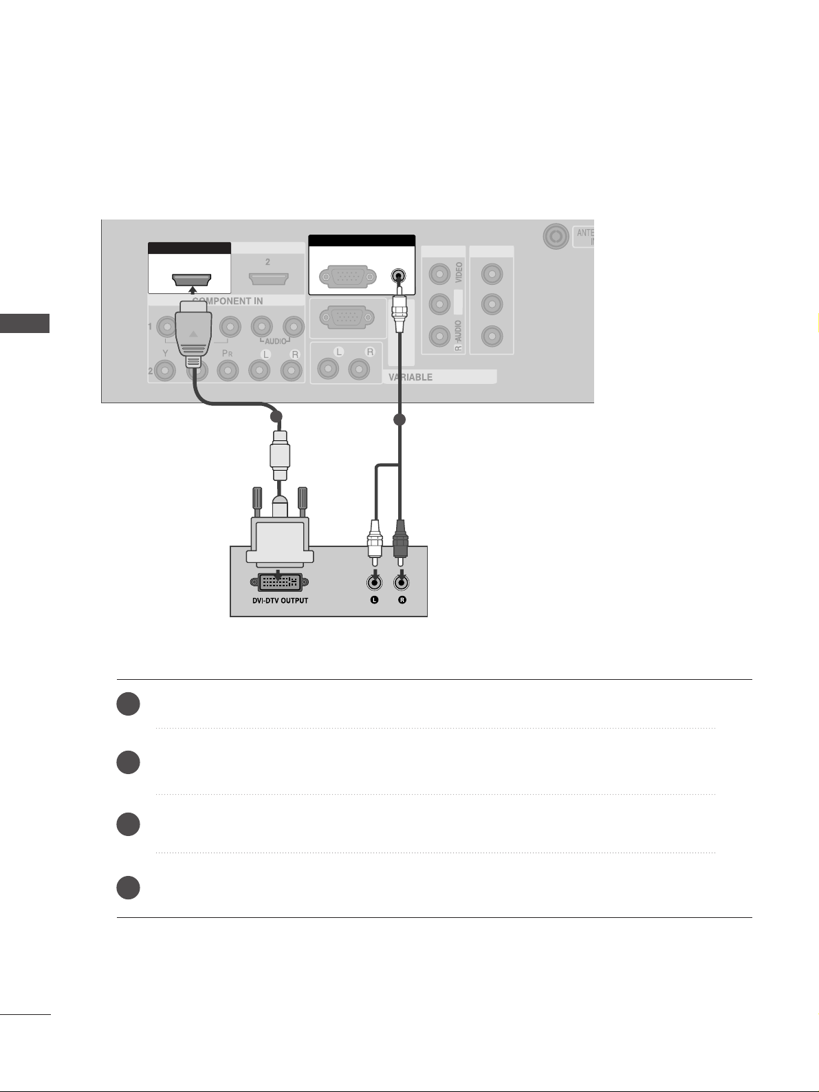
1
2
Connect the DVI output of the digital set-top box to the
HHDD MMII//DD VVII IINN 11
jack on the set.
Connect the audio output of the digital set-top box to the
AAUUDDII OO((RRGGBB//DDVVII))
jack on the set.
Turn on the digital set-top box. (Refer to the owner’s manual for the digital set-top box.
)
Select
HDMI1/DVI input source using the
II NNPPUUTT
button on the remote control.
2
3
4
1
When connecting with a HDMI to DVI cable
19
EXTERNAL EQUIPMENT SETUP
HDMI IN HDMI IN HDMI DVI IN HDMI DVI IN
1
2
COMPONENT INCOMPONENT IN
AUDIO
VIDEO
1 2
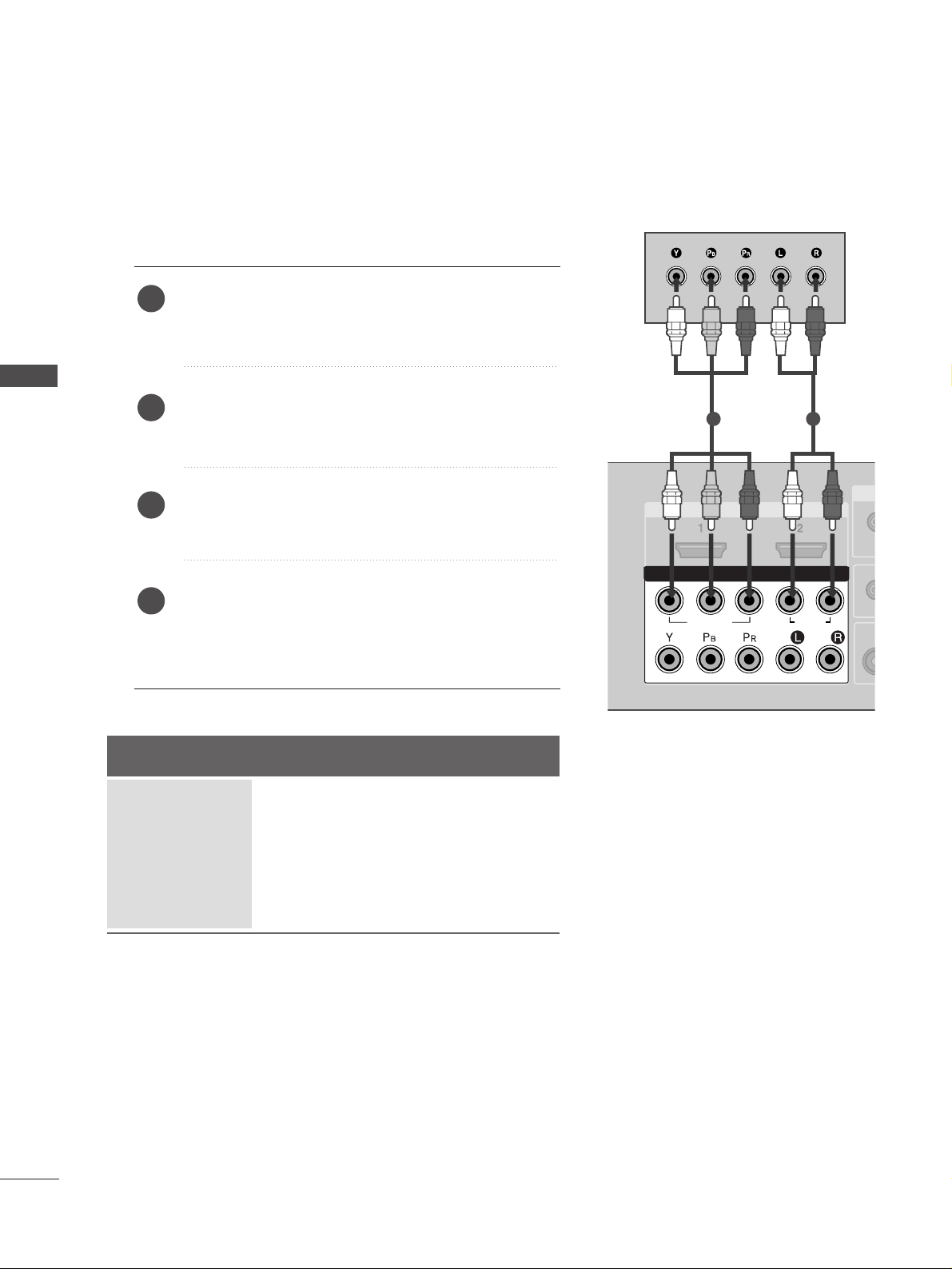
DVD SETUP
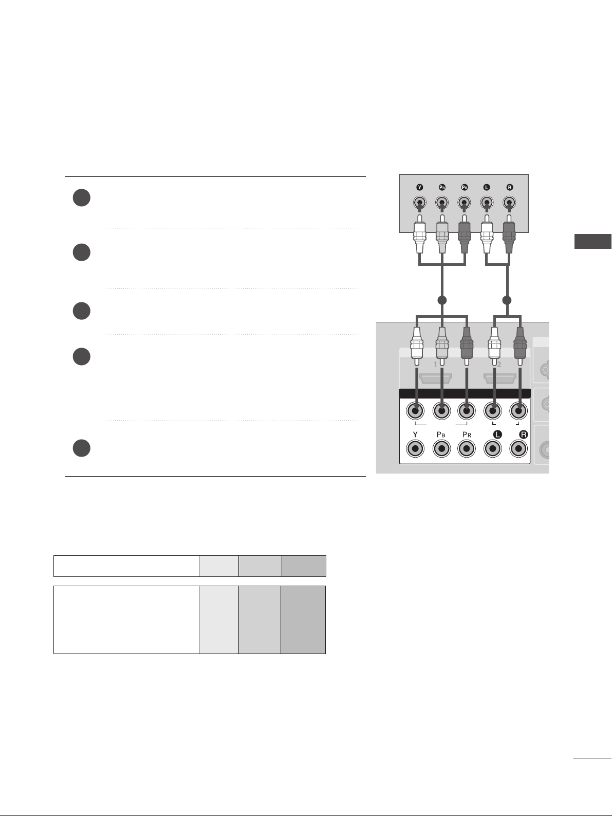
When connecting with a component cable
Component Input ports
To achieve better picture quality, connect a DVD player to the component input ports as shown below.
Component ports on the TV
YPBP
R
Video output ports
on DVD player
Y
Y
Y
Y
PB
B-Y
Cb
Pb
P
R
R-Y
Cr
Pr
Connect the video outputs (Y, PB
, PR
)
of the DVD to the
CC OOMMPPOONNEENN TT IINN VV II DDEEOO
jacks on the set.
Connect the audio outputs of the DVD to the
CC OO MMPPOO--
NNEENNTT IINN AAUUDDIIOO
jacks on the set.
Turn on the DVD player, insert a DVD.
Select
Component
11
input source using the
II NNPPUUTT
but-
ton on the remote control.
If connected to
CC OOMMPPOONNEENN TT IINN22
, select
Component2
input source.
Refer to the DVD player's manual for operating instructions.
2
3
4
5
1
20
EXTERNAL EQUIPMENT SETUP
EXTERNAL EQUIPMENT SETUP
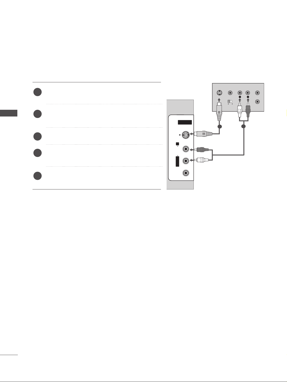
When connecting with an S-Video cable
Connect the S-VIDEO output of the DVD to the
SS--
VVIIDD EEOO
input on the set.
Connect the audio outputs of the DVD to the
AAUUDDIIOO
input jacks on the set.
Turn on the DVD player, insert a DVD.
Select
AV 2 input source using the
II NNPPUUTT
button on
the remote control.
Refer to the DVD player's manual for operating
instructions.
2
3
4
5
1
L
R
S-VIDEO
VIDEO
OUTPUT
SWITCH
ANT IN
ANT OUT
HDMI IN HDMI DVI IN
1
2
COMPONENT IN
AV IN 2AV IN 2
L/L/MONOMONO
R
AUDIOAUDIO
VIDEOVIDEO
S-VIDEOS-VIDEO
1
2
21
EXTERNAL EQUIPMENT SETUP
HDMI IN HDMI IN HDMI DVI IN HDMI DVI IN
HDMI IN HDMI IN HDMI/DVI IN HDMI/DVI IN
1 2
1
When connecting HDMI cable
Connect the HDMI output of the DVD to the
HHDD MMII//DD VVII IINN 11
or
HHDDMM II IINN 22
jack on the set.
Select
HDMI1/DVI or HDMI2 input source using
the
II NNPPUUTT
button on the remote control.
Refer to the DVD player's manual for operating
instructions.
1
GG
If the DVD supports Auto HDMI function, the DVD output
resolution will be automatically set to 1280x720p.
GG
If the DVD player does not support Auto HDMI, you must
set the output resolution appropriately.
To get the best picture quality, adjust the output resolution
of the DVD to 1920x1080i/1080p. (60PC4R
*,
47LB9R*:
1280x720p)
NOTE
!
2
3
22
EXTERNAL EQUIPMENT SETUP
EXTERNAL EQUIPMENT SETUP
AV IN 1AV IN 1 AV OUTAV OUT
L/MONO
AV IN 2
L/ MONO
R
AUDIO
VIDEO
S-VIDEO
ANTENNA
IN
OUTPUT
SWITCH
ANT IN
R
S-VIDEO VIDEO
ANT OUT
L
AUDIO
(RGB/DVI)
(PC)
RS-232C
(CONTROL&SERVICE)
Wall Jack
Antenna
1
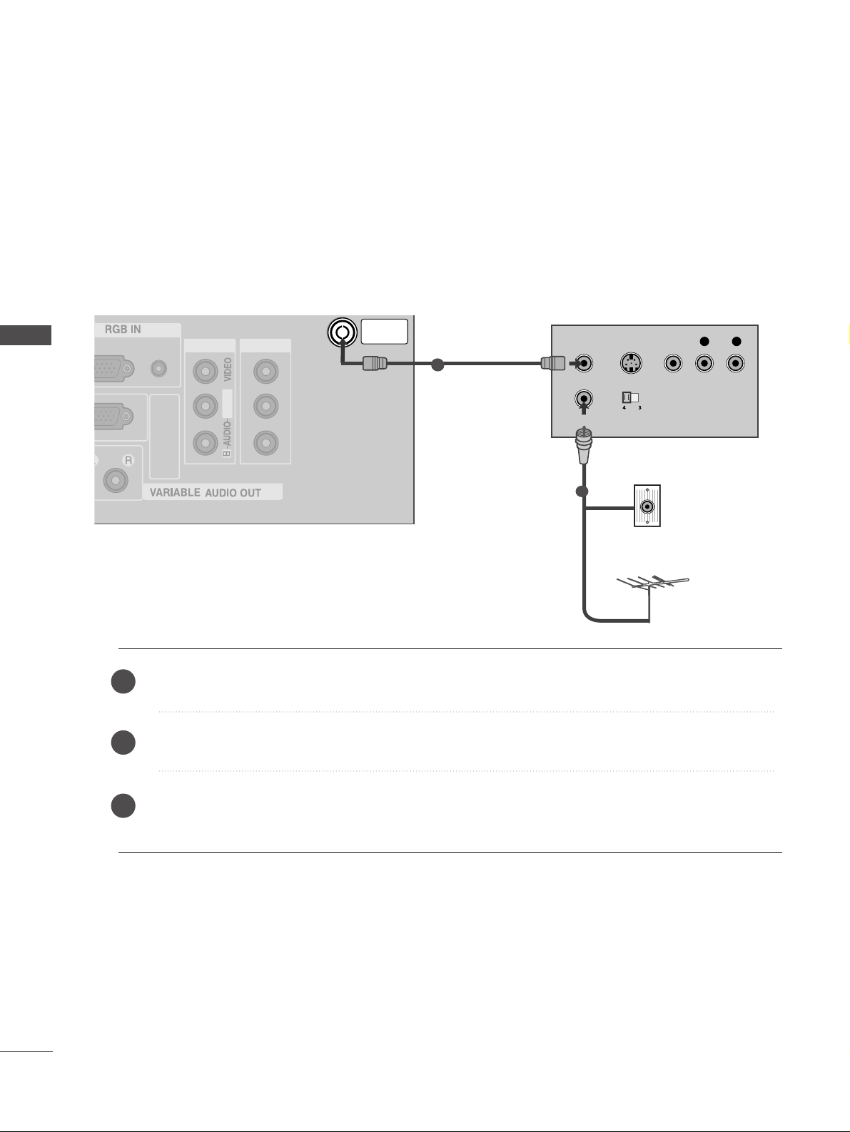
VCR SETUP
When connecting with an antenna
■
To avoid picture noise (interference), allow adequate distance between the VCR and TV.
■
Typically a frozen still picture from a VCR. If 4:3 picture format is used for an extended period the fixed
images on the sides of the screen may remain visible.
Connect the
AANN TT OOUU TT
socket of the VCR to the
AANN TTEENN NNAA IINN
socket on the set.
Connect the antenna cable to the
AANN TT IINN
socket of the VCR.
Press the
PPLLAA YY
button on the VCR and match the appropriate programme between the TV and VCR for
viewing.
1
2
2
3
1
23
EXTERNAL EQUIPMENT SETUP
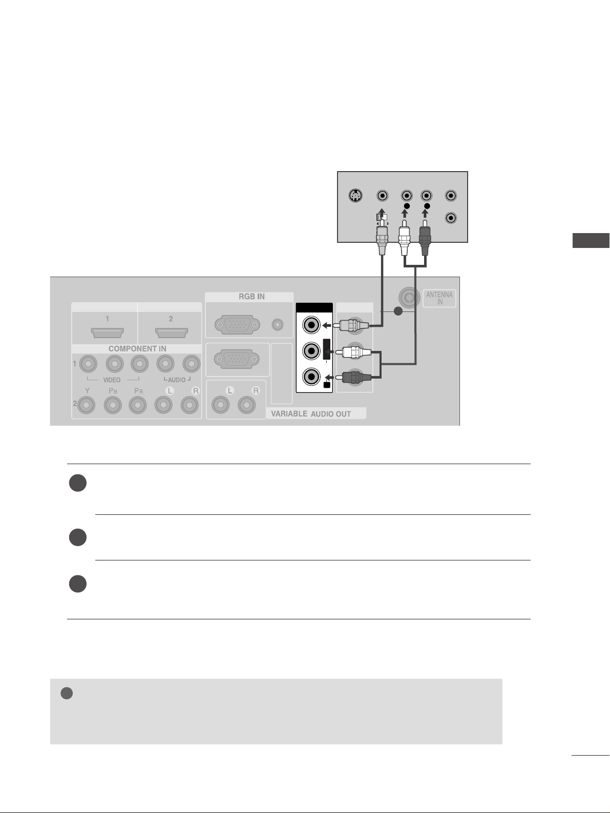
When connecting with a RCA cable
AV IN 1AV IN 1 AV OUTAV OUT
L/MONO
AV IN 2
L/ MONO
R
AUDIO
VIDEO
S-VIDEO
AV IN 1
L/L/MONOMONO
R
AUDIOAUDIO
VIDEOVIDEO
L
R
S-VIDEO
VIDEO
OUTPUT
SWITCH
ANT IN
ANT OUT
AUDIO
(RGB/DVI)
RGB
(PC)
HDMI IN HDMI DVI IN
RS-232C
(CONTROL&SERVICE)
Connect the
AAUUDDIIOO/VVIIDD EEOO
jacks between TV and VCR. Match the jack colours (Video = yellow,
Audio Left = white, and Audio Right = red)
Insert a video tape into the VCR and press PLAY on the VCR. (Refer to the VCR owner’s manual.
)
Select
AV 1 input source using the
II NNPPUUTT
button on the remote control.
If connected to
AAVV II NN22
, select
AV 2 input source.
1
2
3
GG
If you have a mono VCR, connect the audio cable from the VCR to the
AAUUDDIIOO LL//MMOONNOO
jack
of the set.
NOTE
!
1
24
EXTERNAL EQUIPMENT SETUP
EXTERNAL EQUIPMENT SETUP
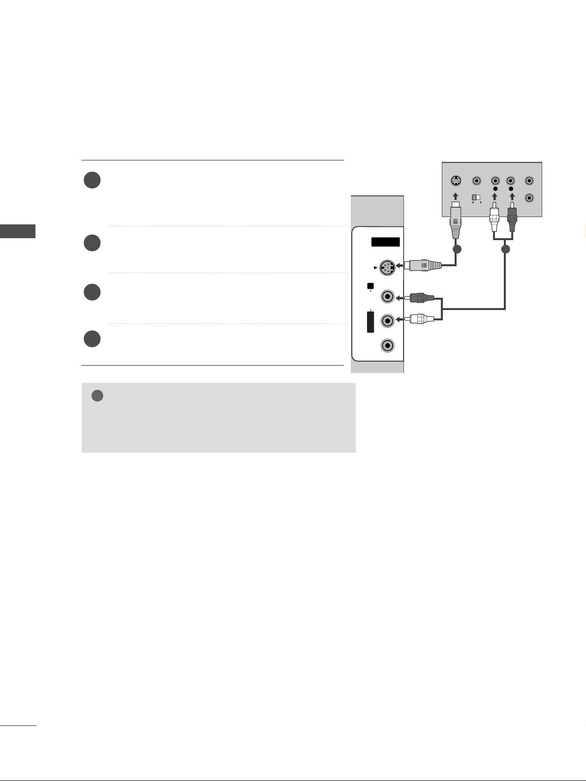
GG
If both S-VIDEO and VIDEO sockets have been connected to
the S-VHS VCR simultaneously, only the S-VIDEO can be
received.
NOTE
!
L
R
S-VIDEO
VIDEO
OUTPUT
SWITCH
ANT IN
ANT OUT
AV IN 2
L/MONOMONO
R
AUDIOAUDIO
VIDEOVIDEO
S-VIDEO
When connecting with an S-Video cable
Connect the S-VIDEO output of the VCR to the
SS--
VVIIDDEEOO
input on the set. The picture quality is
improved; compared to normal composite (RCA cable)
input.
Connect the audio outputs of the VCR to the
AAUUDDIIOO
input jacks on the set.
Insert a video tape into the VCR and press PLAY on
the VCR. (Refer to the VCR owner’s manual.)
Select
AV 2 input source using the
II NNPPUUTT
button on
the remote control.
2
3
4
1
1 2
25
EXTERNAL EQUIPMENT SETUP
AV IN 2V IN 2
L/L/MONOMONO
R
AUDIOAUDIO
VIDEOVIDEO
S-VIDEOS-VIDEO
L R
VIDEO
Camcorder
Video Game Set
1
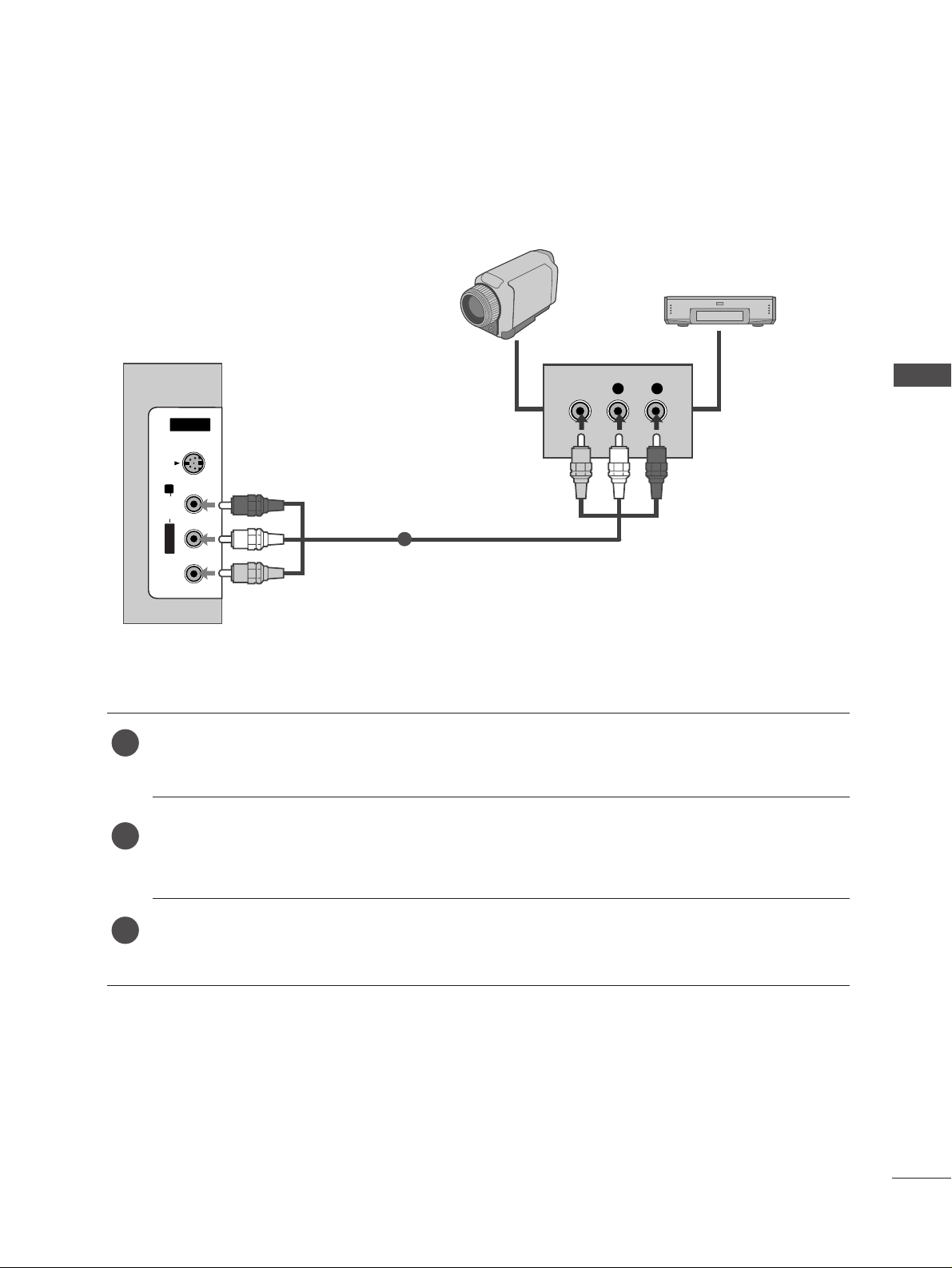
OTHER A/V SOURCE SETUP
Connect the
AAUUDDIIOO/VVIIDD EEOO
jacks between TV and external equipment. Match the jack colours
.
(
Video = yellow, Audio Left = white, and Audio Right = red
)
Select AV 2 input source using the
II NNPPUUTT
button on the remote control.
If connected to
AAVV II NN11
, select
AV 1 input source.
Operate the corresponding external equipment.
Refer to external equipment operating guide.
1
2
3
26
EXTERNAL EQUIPMENT SETUP
AUDIO
(RGB/DVI)
RGB
(PC)
AUDIO
(RGB/DVI)
RGB
(PC)
RGB INRGB IN
HDMI IN
HDMI IN HDMI/DVI IN
12
R
S
-2
3
2
C
IN
(C
O
N
T
R
O
L
&
S
E
R
V
IC
E
)
AV IN 1AV IN 1 AV OUTAV OUT
L/M
O
NO
RGB OUTPUT
AUDIO
HDMI IN HDMI DVI IN
1
2
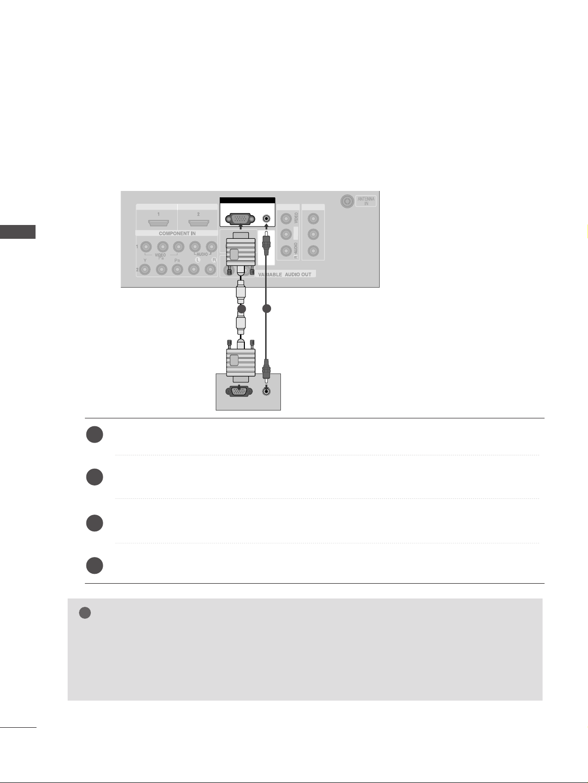
PC SETUP
This TV provides Plug and Play capability, meaning that the PC adjusts automatically to the TV's settings.
When connecting with a D-sub 15 pin cable
Connect the RGB output of the PC to the
RR GGBB ((PPCC
))
jack on the set.
Connect the PC audio output to the
AAUUDDII OO((RRGGBB//DDVVII))
jack on the set.
Turn on the PC and the set.
Select
RGB PC input source using the
II NNPPUUTT
button on the remote control.
2
3
4
1
GG
Check the image on your TV. There may be interference relating to resolution, vertical pattern, contrast or brightness in PC mode. if noise is present, change the PC output to another resolution, change the refresh rate to
another rate or adjust the brightness and contrast on the VIDEO menu until the picture is clear. If the refresh rate
of the PC graphic card can not be changed, change the PC graphic card or consult the manufacturer of the PC
graphic card.
NOTE
!
EXTERNAL EQUIPMENT SETUP
27
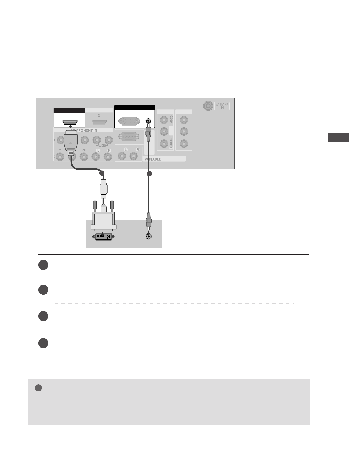
EXTERNAL EQUIPMENT SETUP
DVI-PC OUTPUT
AUDIO
RGB IN
HDMI IN
HDMI DVI IN
HDMI IN HDMI/DVI IN
12
HDMI IN HDMI DVI IN
AUDIO
(RGB/DVI)
RGB
(PC)
HDMI IN HDMI DVI IN
AUDIO
(RGB/DVI)
RGB
(PC)
RGB INRGB IN
HDMI/DVI IN HDMI/DVI IN
1
RS-232C
(CONTROL&SERVICE)
AV IN 1AV IN 1 AV OUTAV OUT
L/M
O
N
O
AUDIO OUT
1
2
Connect the DVI output of the PC to the
HHDD MMII//DD VVII IINN 11
jack on the set.
Connect the PC audio output to the
AAUUDDII OO((RRGGBB//DDVVII))
jack on the set.
Turn on the PC and the set.
Select
HDMI1/DVI input source using the
II NNPPUUTT
button on the remote control.
2
3
4
1
When connecting with a HDMI to DVI cable
GG
HDMI2 source does not support DVI source.
GG
If the PC has a DVI output and no HDMI output, a separated audio connection is necessary.
GG
If the PC does not support Auto DVI, you need to set the output resolution appropriately.
NOTE
!
28
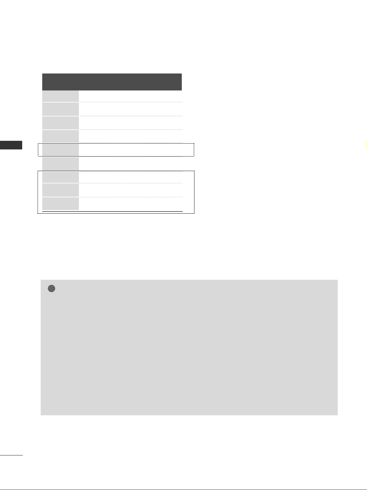
EXTERNAL EQUIPMENT SETUP
Resolution
720x400
640x480
800x600
1024x768
1280x768
1360x768
1280x1024
1600x1200
1920x1080
Supported Display Resolution (RGB[PC]/HDMI[PC]mode)
Horizontal Vertical
Frequency(kHz) Frequency(Hz)
31.5 70.1
31.5 59.9
37.9 60.3
48.4 60.0
47.8 59.9
47.7 59.8
63.7 59.5
75.0 60.0
66.6 60.0
NOTE
!
GG
To get the best picture quality, adjust the PC graphics card to 1920x1080, 60Hz.(60PC4R*,47LB9R*:
1360x768, 60Hz)
GG
Depending on the graphics card, DOS mode may not work if a HDMI to DVI Cable is in use.
GG
When Source Devices connected with HDMI Input, output TV SET Resolution (480p, 720p, 1080i) and
TV SET Display fit EIA/CEA-861-B Specification to Screen. If not, refer to the Manual of HDMI Source
Devices or contact your service center.
GG
If the HDMI Source Device is not connected to the Cable or if there is a poor cable connection, "No signal" is displayed in the HDMI Input. In this case, that Video Resolution is not supported.
GG
Avoid keeping a fixed image on the screen for prolonged periods of time. The fixed image may become
permanently imprinted on the screen.
GG
The synchronization input form for Horizontal and Vertical frequencies is separate.
GG
If you use too long an RGB-PC cable, there may be interference on the screen. We recommend using under
5m of the cable. This provides the best picture quality.
EXTERNAL EQUIPMENT SETUP
(Except 60PC4R*, 47LB9R*)
(60PC4R*, 47LB9R* only)
 Loading...