

LG 42PX3RV-TA, 42PX3RVB-TA, 42PX3RVC-TA, 50PX3R-TA Owner's Manual

PLASMA TV
OWNER’S MANUAL
Please read this manual carefully before operating your set.
Retain it for future reference.
Record model number and serial number of the set.
See the label attached on the back cover and quote this information to your dealer when you require service.
Model number :
Serial number :
P/NO : 3828VA0545A(MF056A, 138P TX) b
2 PLASMA TV
Safety Warnings
Safety Instructions
Safety Instructions
Do not place the set in direct sunlight or near heat
sources such as heat registers, stove and so on.
- This may cause a fire.
Do not use the set in damp place such as a bathroom
or any place where it is likely to get wet.
- This may cause a fire or could give an electric shock.
Bend antenna cable between inside and outside
building to prevent rain from flowing in.
- This may cause water damaged inside the set and could give an
electric shock.
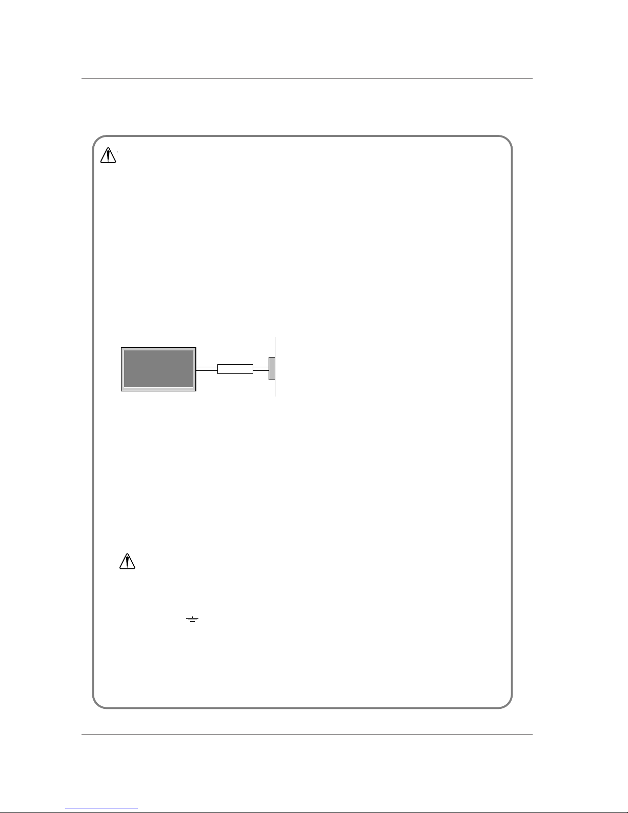
Earth wire should be connected.
- If the earth wire is not connected, there is possible a danger of
electric shock caused by the current leakage.
- If grounding methods are not possible, a separate circuit breaker should be employed and installed by a qualified electrician.
- Do not connect ground to telephone wires, lightning rods or gas
pipe.
Apparatus shall not be exposed to dripping or splashing and no objects filled with liquids, such as vases,
shall be placed on the apparatus.
Do not insert any object into the exhaust vent.
- This may cause a fire or could give an electric shock.
Do not place heavy objects on the set.
- This may cause serious injury to a child or adult.
Do not use water while cleaning the set.
- This may cause damaged the set or could give an electric
shock.
In case of smoke or strange smell from the set, switch
it off ,unplug it from the wall outlet and contact your
dealer or service center.
- This may cause a fire or could give an electric shock.
Do not attempt to service the set yourself. Contact
your dealer or service center.
- This may cause damaged the set or could give an electric
shock.
During a lightning thunder, unplug the set from the
wall outlet and don’t touch an antenna cable.
- This may cause damaged the set or could give an electric
shock.
DISCONNECTING DEVICE FROM MAINS
- Mains plug is the disconnecting device. The plug must remain
readily operable.
W
WARNING
Short-circuit
breaker
Power
supplier
WARNING
in U.K. only
*
This set is supplied with a BS 1363 approved 13 amp mains plug, fused at 13 amp. When replacing the fuse
always use a 13 amp BS 1362, BSI or ASTA approved type. Never use this plug with the fuse cover omitted. To
obtain a replacement fuse cover contact your dealer or “LG Electronics U.K. Ltd.” If the type of plug supplied is not
suitable for the mains sockets in your home, then the plug should be removed and a suitable type fitted.
A mains plug removed from the mains lead of this set must be destroyed. A mains plug with bared wires is
hazardous if inserted in a mains socket. Do not connect either wire to the earth pin, marked with the letter E or
with the earth symbol or coloured green or green and yellow. If any other plug is fitted, use a 13 amp fuse,
either in the plug, or at the distribution board.
The wires in this mains lead are coloured in accordance with the following codes:
As the colours of the wires in the mains lead of this set may not correspond with the coloured marking identifying the terminals in your plug, proceed as follows: The wire which is coloured blue must be connected to the terminal which is marked with the letter N or coloured black. The wire which is coloured brown must be connected
to the terminal which is marked with the letter L or coloured red.
BLUE: NEUTRAL, BROWN: LIVE
Owner’s Manual 3
Safety Warnings
Never touch the power plug with a wet hand.
- This may cause an electric shock.
Disconnect from the mains and remove all connections before moving.
Do not place the set in a built-in installation such as a
bookcase or rack.
- Ventilation required.
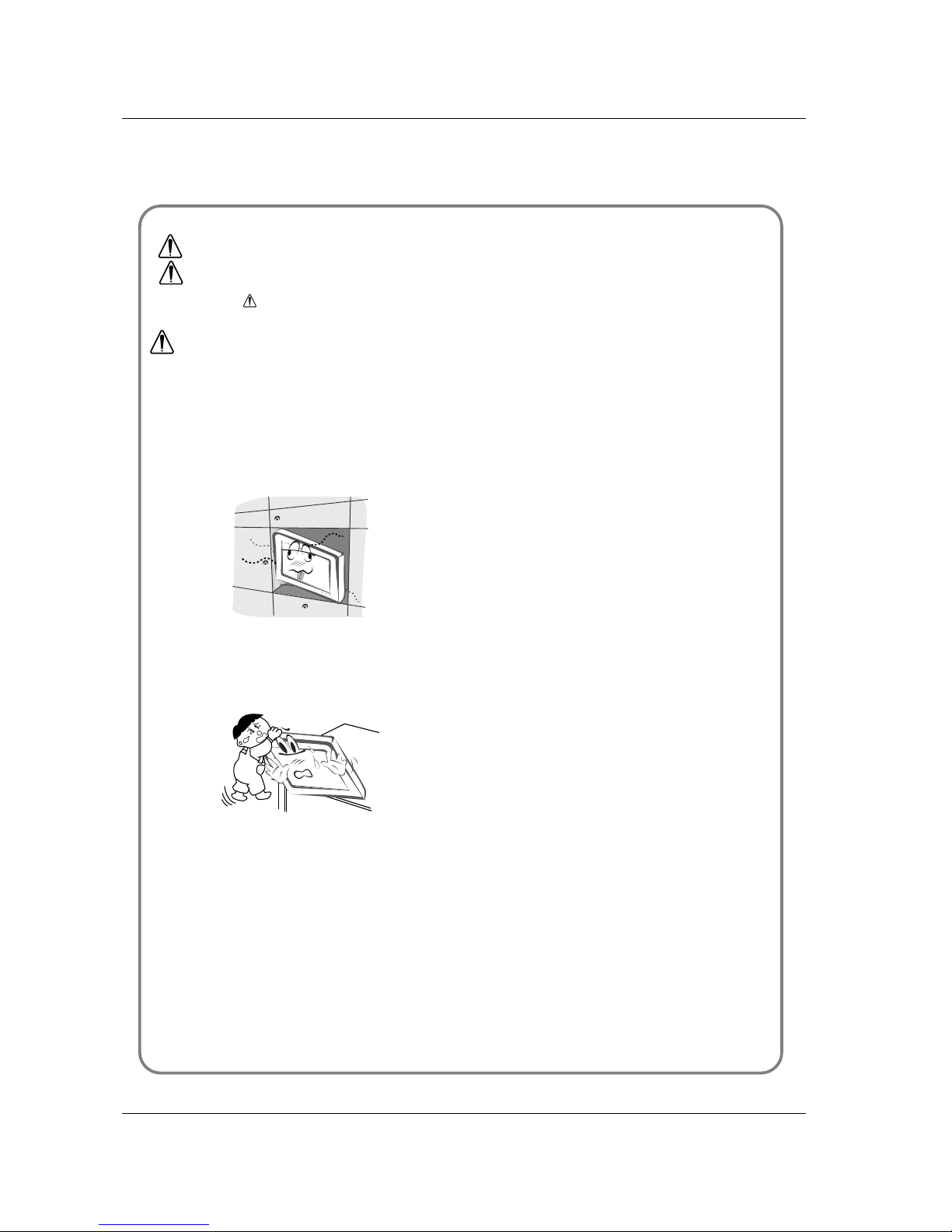
When installing the set on a table, be careful not to
place the edge of its stand.
- This may cause the set to fall, causing serious injury to a child or
adult, and serious damage to the set.
Do not place an outside antenna in the vicinity of overhead power lines or other electric light or power circuits.
- This may cause an electric shock.
There should be enough distance between an outside
antenna and power lines to keep the former from
touching the latter even when the antenna falls.
- This may cause an electric shock.
Do not pull the cord but the plug when unplugging.
- This may cause a fire.
Ensure the power cord doesn’t trail across any hot
objects like a heater.
- This may cause a fire or an electric shock.
Do not plug when the power cord or the plug is damaged or the connecting part of the power outlet is
loose.
- This may cause a fire or an electric shock.
Dispose of used batteries carefully to protect a child
from eating them.
- In case that it eats them, take it to see a doctor immediately.
When moving the set assembled with speakers do not
carry holding the speakers.
- This may cause the set to fall, causing serious injury to a child or
adult, and serious damage to the Monitor.
Unplug this product from the wall outlet before cleaning. Do not use liquid cleaners or aerosol cleaners.
- This may cause damaged the set or could give an electric shock.
Contact the service center once a year to clean the
internal part of the set.
- Accumulated dust can cause mechanical failure.
The distance between eyes and the screen should be
about 5 ~ 7 times as long as diagonal length of the
screen.
- If not, eyes will strain.
Unplug the set from the wall outlet when it is left unattended
and unused for long periods of time or occurred a state of
emergency.
- Accumulated dust may cause a fire or an electric shock from
deterioration or electric leakage.
NOTES
*
Safety instructions have two kinds of information, and each meaning of it is as below.
Take care of danger that may happen under specific condition.
The violation of this instruction may cause serious injuries and even death.
The violation of this instruction may cause light injuries or damage of the
product.
WARNING
NOTES

4 PLASMA TV
Contents
After reading this manual,
keep it in the place where
the user can always
contact easily.
Safety Warnings
Safety Instructions . . . . . . . . . . . . . . . . . . . . . . .2~3
Introduction
Remote Control Key Functions . . . . . . . . . . . . . . . .6
Location and Function of Controls . . . . . . . . . . .7~8
Installation
External Equipment Viewing Setups . . . . . . . . .9~12
Displayable Monitor Specification . . . . . . . . . . . . .13
HDMI . . . . . . . . . . . . . . . . . . . . . . . . . . . . . . .14~15
Accessories . . . . . . . . . . . . . . . . . . . . . . . . . . . . .16
Installation Options . . . . . . . . . . . . . . . . . . . . . . .17
Operation
Turning on the Set . . . . . . . . . . . . . . . . . . . . . . . .18
On-Screen Menu Language Selection (option) . . .18
Channel Menu Options
Auto Programme Tuning . . . . . . . . . . . . . . . . . . .19
Manual Programme Tuning . . . . . . . . . . . . . . . . .19
Fine Tuning . . . . . . . . . . . . . . . . . . . . . . . . . . . . .20
Assigning a Station Name . . . . . . . . . . . . . . . . . .20
Booster (option) . . . . . . . . . . . . . . . . . . . . . . . . . .20
Programme Edit . . . . . . . . . . . . . . . . . . . . . . . . . .21
Favourite Programme . . . . . . . . . . . . . . . . . . . . .21
Calling the Programme Table . . . . . . . . . . . . . . . .21
Picture Menu Options
PSM (Picture Status Memory) . . . . . . . . . . . . . . .22
CSM (Colour Status Memory) . . . . . . . . . . . . . . .22
Manual Colour Temperature Control . . . . . . . . . .22
. . . . . . . . . . . . . . . . . . . . . . . . . . . . . . . . . .22
sRGB . . . . . . . . . . . . . . . . . . . . . . . . . . . . . . . . .23
ACM (Active Colour Management) . . . . . . . . . . . .23
Manual Picture Control . . . . . . . . . . . . . . . . . . . .23
Sound Menu Options
SSM (Sound Status Memory) . . . . . . . . . . . . . . . .24
BBE . . . . . . . . . . . . . . . . . . . . . . . . . . . . . . . . . . .24
AVL(Auto Volume Leveler) . . . . . . . . . . . . . . . . .24
Adjusting Sound Control . . . . . . . . . . . . . . . . . . .24
TV speaker . . . . . . . . . . . . . . . . . . . . . . . . . . . . .25
Stereo/Dual Reception . . . . . . . . . . . . . . . . . . . . .25
NICAM Reception (option) . . . . . . . . . . . . . . . . . .25
Time Menu Options
Setting the Clock . . . . . . . . . . . . . . . . . . . . . . . . .26
Setting the On/Off Timer . . . . . . . . . . . . . . . . . . . 26
Auto Sleep . . . . . . . . . . . . . . . . . . . . . . . . . . . . . .26
Sleep Timer . . . . . . . . . . . . . . . . . . . . . . . . . . . . .26
Special Menu Options
Child Lock . . . . . . . . . . . . . . . . . . . . . . . . . . . . . .27
ISM (Image Sticking Minimization) Method . . . . . .27
Low Power . . . . . . . . . . . . . . . . . . . . . . . . . . . . . .28
Demo . . . . . . . . . . . . . . . . . . . . . . . . . . . . .28
Screen Menu Options
Auto Configure . . . . . . . . . . . . . . . . . . . . . . . . . .29
Manual Configure . . . . . . . . . . . . . . . . . . . . . . . .29
Selecting Wide VGA/XGA mode . . . . . . . . . . . . .29
Setting Picture Format . . . . . . . . . . . . . . . . . . . . .30
Picture Size Zoom . . . . . . . . . . . . . . . . . . . . . . . .30
Screen Position . . . . . . . . . . . . . . . . . . . . . . . . . .31
Cinema . . . . . . . . . . . . . . . . . . . . . . . . . . . . . . . .31
NR (Noise Reduction) . . . . . . . . . . . . . . . . . . . . .31
Initializing (Reset to original factory value) . . . . . .31
PIP (Picture-in-Picture) Feature
Watching PIP . . . . . . . . . . . . . . . . . . . . . . . . . . . .32
Programme Selection for Sub Picture . . . . . . . . . .32
Selecting an Input Signal Source for the PIP . . . .32
Moving the PIP (PIP mode only) . . . . . . . . . . . . .32
POP (Picture-out-of-Picture: Channel Scan) . . . . .32
Picture Size . . . . . . . . . . . . . . . . . . . . . . . . . . . . .32
Adjusting the screen for the PIP . . . . . . . . . . . . . .32
Adjusting PIP Transparency (PIP mode only) . . . . 32
Teletext (option)
Switch on/off . . . . . . . . . . . . . . . . . . . . . . . . . . . .33
SIMPLE Text (option) . . . . . . . . . . . . . . . . . . . . . .33
TOP Text (option) . . . . . . . . . . . . . . . . . . . . . . . . .33
FASTEXT . . . . . . . . . . . . . . . . . . . . . . . . . . . . . . 34
Special Teletext Functions . . . . . . . . . . . . . . . . . .34
Miscellaneous
External Control Device Setup . . . . . . . . . . . .35~41
IR Code (NEC Format) . . . . . . . . . . . . . . . . . .42~43
Troubleshooting Checklist . . . . . . . . . . . . . . . . . .46
Product Specifications . . . . . . . . . . . . . . . . . . . . .47
Contents
Contents

Owner’s Manual 5
Introduction
Introduction
Introduction
What is a Plasma Display ?
If voltage is inputted to gas in glass panels, ultraviolet rays is outputted and fused with a fluorescent substance. At this moment,
light is emitted. APlasma Display is a next generation flat Display using this phenomenon.
160° - Wide angle range of vision
A Plasma Display provides more than 160° angle range of vision so that you can get a picture without distortion from any
direction.
Easy installation
A Plasma Display is much lighter and smaller than other same class products so that you can install the Plasma Display
at the desired place.
Big screen
The screen of a Plasma Display is 42" (or 50") so that you can get vivid experience as if you are in a theater.
Multimedia Plasma Display
A Plasma Display can be connected with a computer so that you can use it as a screen for conference, game, internet
and so on.
The explanation about coloured dots may be present on PDP screen
The PDP which is the display device of this product is composed of 0.9 to 2.2 million cells and a few cell defects can occur
in the manufacture of the PDP. Several coloured dots visible on the screen would be acceptable, in line with other PDP
manufacturers and would not mean that the PDP is faulty. We hope you will understand that the product which corresponds to this standard is regarded as acceptable. It means that it could not be changed or refunded.
We promise that we'll do our best to develop our technology to minimize the cell defects.
The explanation about noise of 42" (or 50") PDP (option)
In the same way that a fan is used in a PC to keep the CPU cool, the PDP is equipped with cooling fans to improve the
reliability of this product. Therefore, a certain level of noise could occur when the fan is operated. This noise doesn't have
any negative effect on its efficiency and reliability and it's also determined to have no difficulty while using this product.
The noise from the fans is normal in the operation of this product. We hope you will understand that a certain level of noise
is acceptable. It means that it is not changeable nor refundable.
TO AVOID BURNING IMAGE INTO THE DISPLAY, DO NOT HAVE A STILL IMAGE ON SCREEN FOR EXTENDED PERIOD
OF TIME. IMAGE AFTER BURN WILL NOT BE COVERED UNDER WARRANTY ie.Menus, Video games, Borders or LOGOS
WARNING
This is Class B product. In a domestic environment this product may cause radio interference in which
case the user may be required to take adequate measures.
WARNING
TO REDUCE THE RISK OF FIRE AND ELECTRIC SHOCK, DO NOT EXPOSE THIS PRODUCT TO
RAIN OR MOISTURE.
6 PLASMA TV
Introduction
Remote Control Key Functions
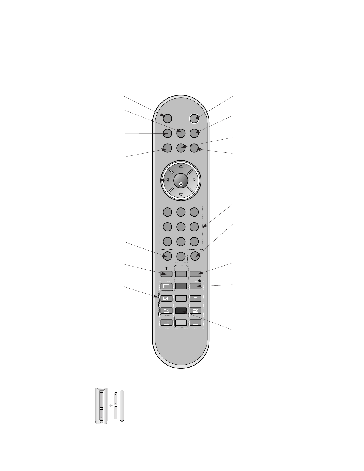
Remote Control Key Functions
- When using the remote control aim it at the remote control sensor of the set.
- There's maybe a defect in consecutive operation of remote control in specified brightness according to this set feature.
• Open the battery compartment cover on the back side and
insert the batteries with correct polarity.
• Install two 1.5V alkaline batteries of AAA type. Don’t mix used
batteries with new batteries.
Installing Batteries
POWERMUTE
TV/AV
MULTIMEDIA
LIST ARC
MENU
PR
PR
VOL
OK
1 2 3
4 5 6
7
PSM
SSM
8 9
0
VOL
PIP/DW
SLEEP
REVEAL
TEXT/
PIP PR+
WIN. SIZE
MIX
PIP PR-
POSITION
TIME
SWAP
HOLD
INDEX
PIP INPUT
?
i
I/II
MULTIMEDIA
Selects the Component, RGB or DVI
modes.
switches the set on from standby.
PIP/DW
Switches the sub picture on or off.
Selects PIP or DW modes.
PIP PR + /-
Selects a programme for the sub picture.
SWAP
Alternates between main and sub pic-
ture.
PIP INPUT
Selects the input mode for the sub pic-
ture.
WIN.SIZE
Adjusts the sub picture size.
POSITION
Moves the sub picture to
DD/ EE
or FF/
GG
direction.
POWER
switches the set on from standby or
off to standby.
ARC
Changes the picture format.
MENU
Displays on screen menus one by
one.
Exits the current menu.
Memorizes menu changes.
SWAP
Returns to the previously viewed
programme.
Note : This function works only
when
Favourite programme
is
set to
Off
. Otherwise each press of
this button will select a stored
favorite programme.
SSM
To select the sound appropriate to
your viewing programme character.
NUMBER buttons
SLEEP
Sets the sleep timer.
I/II
Selects the language during dual language broadcast.
Selects the sound output.
TEXT/
*
These buttons are used for teletext.
For further details, see the ‘Teletext’
section.
Note : In teletext mode, the PIP PR
+/-, SWAPand PIP INPUT buttons are
used for teletext function.
LIST
Displays the programme table.
TV/AV
Selects the TV, AV, Component, RGB
or DVI modes.
switches the set on from standby.
MUTE
Switches the sound on or off.
DD/ EE
(Programme Up/Down)
selects a programme or a menu item.
switches the set on from standby.
FF/ GG
(Volume Up/Down)
adjusts the volume.
adjusts menu settings.
OK
accepts your selection or displays the
current mode.
PSM
Adjusts the factory preset picture
according to the room.
No function
Owner’s Manual 7
Introduction
Location and Function of Controls
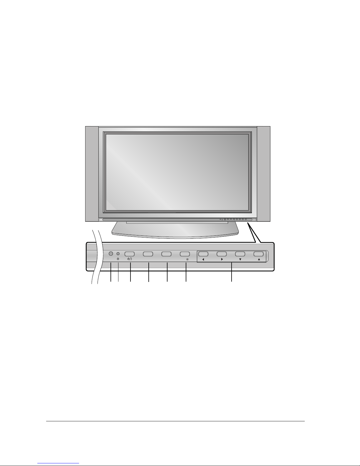
Location and Function of Controls
<Front Panel Controls>
PR
VOL
MENUTV/AV OK
PR
VOL
MENUTV/AV OK
1
32
4
5 6 7
1. Remote Control Sensor
2. Power Indicator
Illuminates red in standby mode, Illuminates green when the
set is turned on.
3. Power Button
Switches the set on from standby or off to standby.
4. TV/AV Button
Selects the TV, AV, Component, RGB or HDMI modes.
Switches the set on from standby.
5. MENU
Displays on screen menus one by one.
Exits the current menu.
Memorizes menu changes.
6. OK
Accepts your selection or displays the current mode.
7.DD/ EE(Programme Up/Down)
Selects a programme or a menu item.
Switches the set on from standby.
FF/ GG
(Volume Up/Down)
Adjusts the volume.
Adjusts menu settings.
8 PLASMA TV
Introduction
Location and Function of Controls
Location and Function of Controls
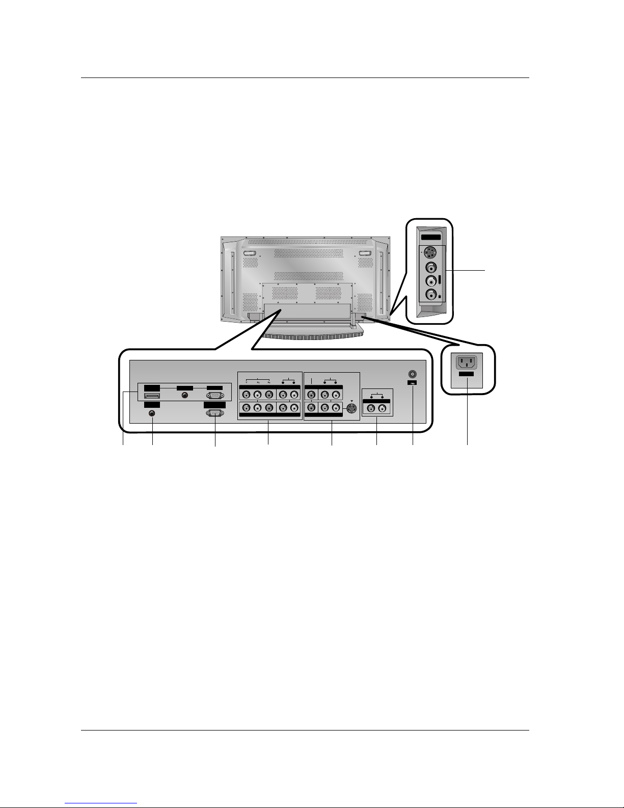
<Back Panel>
S-VIDEO
VIDEOAUDIOR
L/MONO
A/V INPUT2A/V INPUT2
AC INPUT
RS-232C INPUT
(CONTROL/SERVICE)
S-VIDEOS-VIDEO
(MONO)
AUDIO AUDIO
L R
AUDIO AUDIO
L R
AUDIO AUDIO
L R
Antenna
VIDEO VIDEO
REMOTE
CONTROL
HDMI/
DVI(VIDEO)
AUDIO INPUT
RGB INPUT
VIDEOVIDEO
COMPONENTCOMPONENT INPUT INPUT 2 2
COMPONENTCOMPONENT INPUT INPUT 1 1
MONITMONITOR OUTPUTOR OUTPUT
A/V INPUTA/V INPUT 1 1
VVARIABLE ARIABLE AUDIO OUTAUDIO OUT
1. HDMI(DVI VIDEO) / AUDIO INPUT / RGB INPUT
Connect the monitor output socket of the PERSONAL COMPUTER, DVD or STB to this socket.
Note: If you want to use RGB/DVI audio, we strongly
recommend that you use the cable that has a core, or the
EMI Filter core along with separate cable.
2. REMOTE CONTROL
3. RS-232C INPUT(CONTROL/SERVICE) PORT
Connect to the RS-232C port on a PC.
4. COMPONENT INPUT
Connect DVD video outputs to Y, PB, PR of COMPONENT
INPUT and audio outputs to Audio sockets of AUDIO INPUT.
5. VIDEO/AUDIO IN/OUT SOCKETS (A/V INPUT 1)
Connect the video/audio out sockets of external equipment
to these sockets.
S-VIDEO/AUDIO IN SOCKETS
Connect the S-VIDEO out socket of an VCR to the S-VIDEO
socket.
Connect the audio out sockets of the VCR to the audio sockets as in A/V INPUT 1.
6. VARIABLE AUDIO OUTPUT
7. ANTENNAINPUT
8. POWER CORD SOCKET
This the set operates on an AC power. The voltage is indicated on the Specifications page. Never attempt to operate the
set on DC power.
9. AUDIO/VIDEO INPUT (A/V INPUT 2)
S-VIDEO/AUDIO IN SOCKETS
1
4
2
3 5
7
8
6
9
- Shown is a simplified representation of the set.
- Here shown may be somewhat different from your set.
- This manual explains the features available on the 42PX3RV series.
Owner’s Manual 9
Installation
External Equipment V
External Equipment V
iewing Setups
iewing Setups
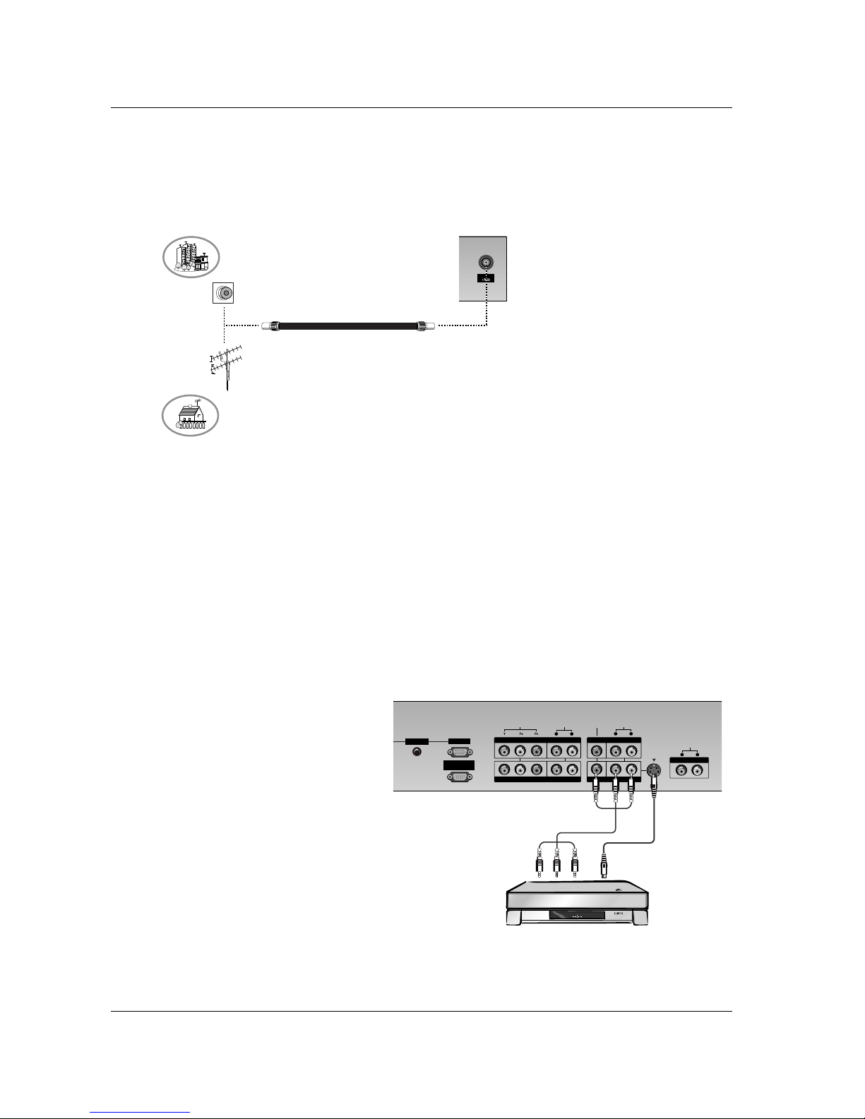
- Be careful for the bronze wire not to be banded in connecting to antenna input port.
Antenna Connection
Antenna
Watching VCR
- When connecting the set to external equipment, match the colours of connecting ports (Video - yellow, Audio (L) - white, Audio
(R) -red).
- Connect the VIDEO INPUT socket (yellow) of external equipment to the VIDEO INPUT on the set.
- If you have a mono VCR, connect the audio cable from the VCR to the AUDIO (L/MONO) input on the set.
- If you connect an S-VIDEO VCR to the S-VIDEO input, the picture quality is improved; compared to connecting a regular VCR
to the Video input.
- Use the orbiter function to avoid having a fixed image remain on the screen for a long period of time. Typically a frozen still picture from a VCR. (Refer to p. 27)
If a 4:3 picture format is used, the fixed image may remain visible on the screen.
- To avoid picture noise (interference), leave an adequate distance between the VCR and set.
Watching TV programmes
- Turn the set on and select the programme you
want.
Watching VCR
1. Use the TV/AV button on the remote control to
select
AV1 or AV2.
- If both S-VIDEO and VIDEO sockets have been
connected to the S-VHS VCR simultaneously,
only the
S-VIDEO can be received.
2. Insert a video tape into the VCR and press the
PLAY button on the VCR.
(See VCR owner’s manual)
RS-232C INPUT
(CONTROL/SERVICE)
S-VIDEOS-VIDEO
(MONO)
AUDIO AUDIO
L R
AUDIO AUDIO
L R
AUDIO AUDIO
L R
VIDEO VIDEO
AUDIO INPUT
RGB INPUT
VIDEOVI DEO
COMPONENTCOMPONENT INPUT INPUT 2 2
COMPONENTCOMPONENT INPUT INPUT 1 1
MONITMONITOR OUTPUTOR OUTPUT
A/V INPUTA/V INPUT 1 1
VVARIABLE ARIABLE AUDIO OUTAUDIO OUT
Apartments
(connecting to wall antenna socket)
Private house
(connecting to wall outdoor antenna)
outdoor antenna
wall antenna socket
VHF antenna
UHF antenna
RF coaxial wire (75 ohms)
< Back panel of the set >
< Back panel of the set >
< VCR >
10 PLASMA TV
Installation
External Equipment V
External Equipment V
iewing Setups
iewing Setups
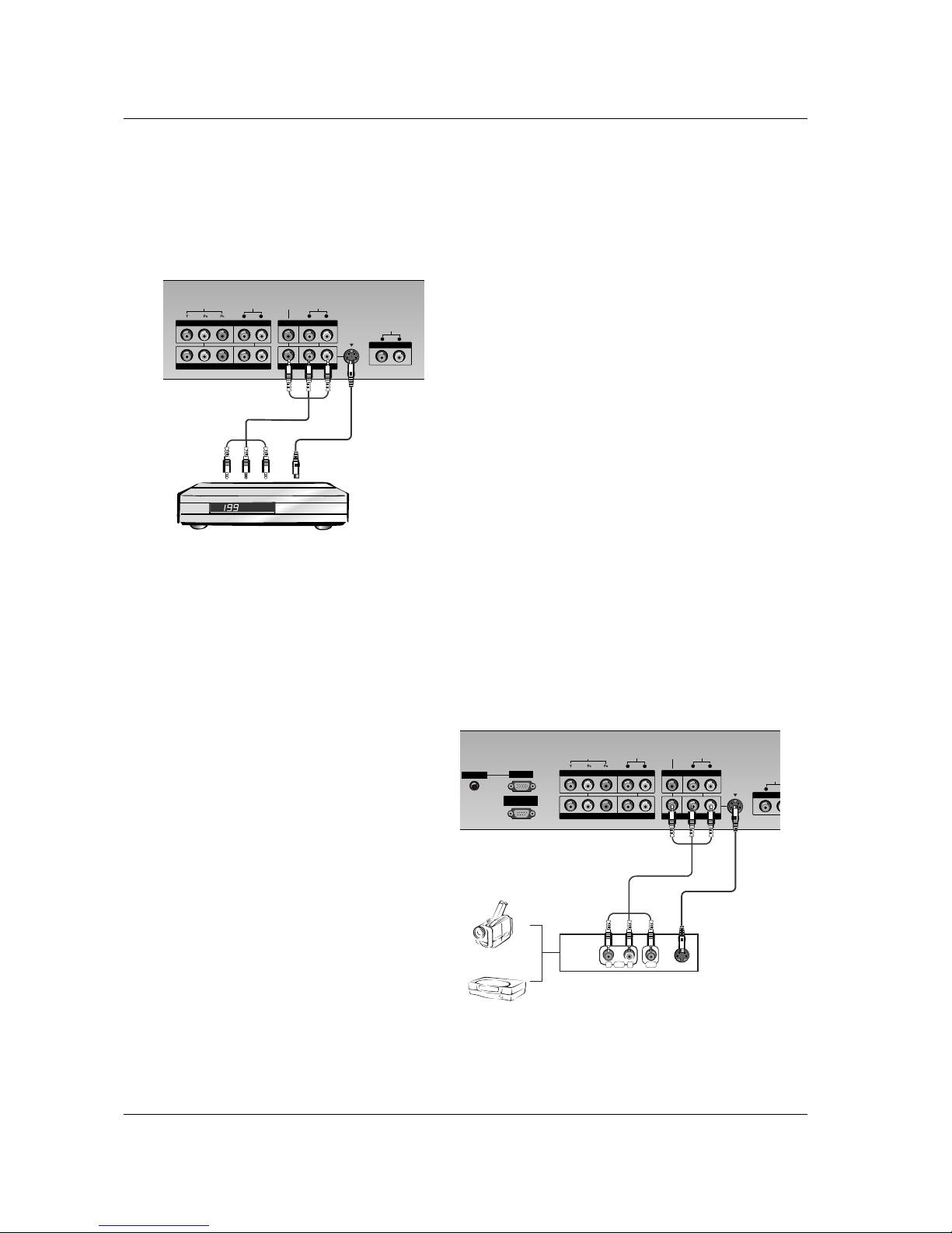
Watching Cable TV
- After subscribing for a local cable TV station and installing a converter you can watch cable TV.
- For further information of cable TV, contact the local cable TV station.
To watch cable TV
1. Use the TV/AV button on the remote control to
select
AV1 or AV2.
- If both S-VIDEO and VIDEO sockets have been
connected to the Cable box simultaneously, only
the
S-VIDEO can be received.
2. Select your desired channel with the remote
control for cable box.
Watching external AV source
- When connecting the set to an external source, match the colours of AUDIO/VIDEO input jacks on the set with the output jacks
on the audio/video equipment: Video = yellow, Audio (Left) = white, Audio (Right) = red.
How to use
1. Use the TV/AV button on the remote control to
select AV1 or AV2.
- If both S-VIDEO and VIDEO sockets have been
connected to the S-VHS VCR simultaneously,
only the
S-VIDEO can be received.
2. Operate the corresponding external equipment.
See external equipment operating guide.
RS-232C INPUT
(CONTROL/SERVICE)
S-VIDEOS-VIDEO
(MONO)
AUDIO AUDIO
L R
AUDIO AUDIO
L R
AUDIOAUD IO
L
VIDEO VIDEO
AUDIO INPUT
RGB INPUT
VIDEOVI DEO
COMPONENTCOMPONENT INPUT INPUT 2 2
COMPONENTCOMPONENT INPUT INPUT 1 1
MONITMONITOR OUTPUTOR OUTPUT
A/V INPUTA/V INPUT 1 1
VVARIABLE ARIABLE AUDIAUDI
R L
AUDIO VIDEO
S-VIDEOS-VIDEO
(MONO)
AUDIO AUDIO
L R
AUDIO AUDIO
L R
AUDIO AUDIO
L R
VIDEO VIDEO
VIDEOVI DEO
COMPONENTCOMPONENT INPUT INPUT 2 2
COMPONENTCOMPONENT INPUT INPUT 1 1
MONITMONITOR OUTPUTOR OUTPUT
A/V INPUTA/V INPUT 1 1
VVARIABLE ARIABLE AUDIO OUTAUDIO OUT
< Back panel of the set >
< Cable box >
< Back panel of the set >
Camcorder
Video game set
Owner’s Manual 11
Installation
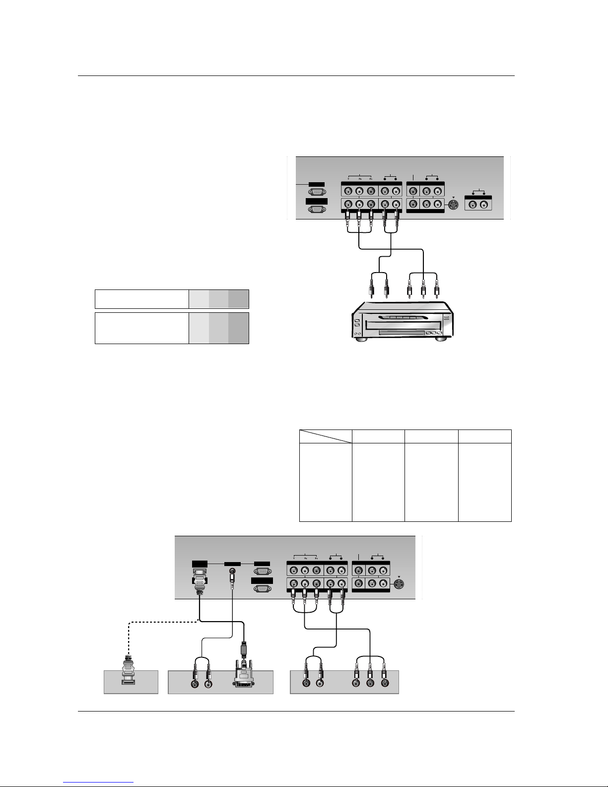
Watching DVD
How to connect
Connect DVD video outputs to Y, PB, PR of COMPONENT INPUT and audio outputs to Audio sockets of
AUDIO INPUT.
How to use
1. Turn on the DVD player, and insert a DVD.
2. Use TV/AV or MULTIMEDIA button on the remote
control to select
Component 1 or Component 2.
Refer to the DVD player's manual for operating
instructions.
• Component Input ports
You can get better picture quality if you connect
DVD player with component input ports as below.
Component ports of the
set
Y
PB
PR
Video output ports
of DVD player
Y
Y
Y
Y
Pb
B-Y
Cb
PB
Pr
R-Y
Cr
P
R
RS-232C INPUT
(CONTROL/SERVICE)
S-VIDEOS-VIDEO
(MONO)
AUDIO AUDIO
L R
AUDIO AUDIO
L R
AUDIO AUDIO
L R
VIDEO VIDEO
RGB INPUT
VIDEOVI DEO
COMPONENTCOMPONENT INPUT INPUT 2 2
COMPONENTCOMPONENT INPUT INPUT 1 1
MONITMONITOR OUTPUTOR OUTPUT
A/V INPUTA/V INPUT 1 1
VVARIABLE ARIABLE AUDIO OUTAUDIO OUT
R
R
R
R
< Back panel of the set >
< DVD player >
Watching DTV (option)
- To watch digitally broadcast programs, purchase and connect a digital set-top box.
How to connect
1. Use the set’s COMPONENT (Y, PB, PR) INPUT, RGB or
HDMI jack for video connections, depending on your settop box connector. Then, make the corresponding audio
connections.
How to use
1. Turn on the digital set-top box. (Refer to the owner’s
manual for the digital set-top box.)
2. Use TV/AV or MULTIMEDIA on the remote control to
select Component 1, Component 2, RGB or HDMI.
RS-232C INPUT
(CONTROL/SERVICE)
S-VIDEOS-VIDEO
(MONO)
AUDIO AUDIO
L R
AUDIO AUDIO
L R
VIDEO VIDEO
REMOTE
CONTROL
HDMI/
DVI(VIDEO)
AUDIO INPUT
RGB INPUT
VIDEOVI DEO
COMPONENTCOMPONENT INPUT INPUT 2 2
COMPONENTCOMPONENT INPUT INPUT 1 1
MONITMONITOR OUTPUTOR OUTPUT
A/V INPUTA/V INPUT 1 1
(R) AUDI O (L) Y P
B R
P
R
R
R
R
(R) AUDI O (L)
HDMI OUT PUT
R
HDMI OUT PUT
• DTV Input signal
480i
576i
480p
576p
720p
1080i
Mode
Terminal
Component
o
o
o
o
o
o
RGB (DTV)
x
x
o
o
o
o
HDMI (DTV)
x
x
o
o
o
o
< Back panel of the set >
< Digital Set-top box >
or or
12 PLASMA TV
Installation
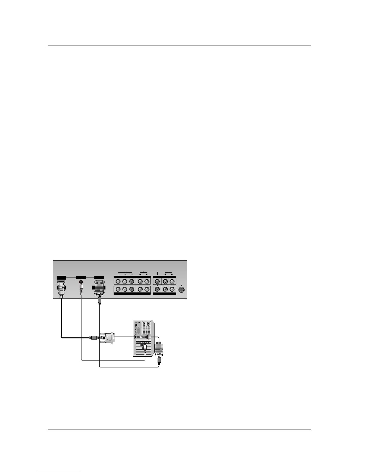
Connecting PC
- To enjoy vivid picture and sound, connect a PC to the set.
- Avoid keeping a fixed image on the set’s screen for a long period of time. The fixed image may become permanently imprinted on
the screen; use a screen saver when possible.
- Connect PC to the RGB INPUT(PC INPUT) or HDMI INPUT(DIGITAL RGB INPUT) port of the set; change the resolution output
of PC accordingly.
- There might be a noise according to some resolution, vertical pattern, contrast or brightness in PC mode. Then change the PC
mode into other resolution or change the refresh rate into other rate or adjust the brightness and contrast on the menu until the
picture is clean. If the refresh rate of the PC graphic card can not be changed, change the PC graphic card or consult it to the
manufacturer of the PC graphic card.
- The synchronization input form for Horizontal and Vertical frequencies is separate.
Setup Instructions to Connect a PC to your set
- We recommend using 1024x768, 60Hz for the PC mode, they provide the best picture quality.
In 42PX3RV series, we recommend using 640x480, 60Hz for the PC mode, they provide the best picture quality.
- If the resolution of PC is over UXGA, there will be no picture on the set.
- Connect the signal cable from the monitor output port of the PC to the RGB INPUT port of the set or the signal cable from the
HDMI output port of the PC to the HDMI INPUT port on the set.
- Connect the audio cable from the PC to the Audio input on the set. (Audio cables are not included with the set).
- If using a sound card, adjust PC sound as required.
- This set apply a VESA Plug and Play Solution. The set provides EDID data to the PC system with a DDC protocol. The PC adjusts
automatically to use this set.
- DDC protocol is preset for RGB (Analog RGB), HDMI (Digital RGB) mode.
- If required, adjust the set settings for Plug and Play functionally.
- If graphic card on the PC does not output analog and digital RGB simultaneously, connect only one of both RGB INPUT or HDMI
INPUT to display the PC on the set.
If graphic card on the PC does output analog and digital RGB simultaneously, set the set to either RGB or HDMI ; (the other mode
is set to Plug and Play automatically by the set.)
- DOS mode may not work depending on video card if you use a HDMI to DVI cable.
- When you use too long RGB-PC cable, there might be a noise on the screen. We recommend using under 5m of the cable. It provides the best picture quality.
RS-232C INPUT
(CONTROL/SERVICE)
S-VIDEOS-VIDEO
(MONO)
AUDIO AUDIO
L R
AUDIO AUDIO
L R
VIDEO VIDEO
REMOTE
CONTROL
HDMI/
DVI(VIDEO)
AUDIO INPUT
RGB INPUT
VIDEOVI DEO
COMPONENTCOMPONENT INPUT INPUT 2 2
COMPONENTCOMPONENT INPUT INPUT 1 1
MONITMONITOR OUTPUTOR OUTPUT
A/V INPUTA/V INPUT 1 1
PC Setup
1. Turn on the PC and apply power to the set.
2. Turn on the display by pressing the POWER button on
the set’s remote control.
3. Use the TV/AV or MULTIMEDIA button on the remote
control to select the RGB or HDMI input source.
4. Set the resolution output of the PC to SXGA or under
(1280 x 1024, 60Hz). (Refer to p. 13)
External Equipment V
External Equipment V
iewing Setups
iewing Setups
< Back panel of the set >
Owner’s Manual 13
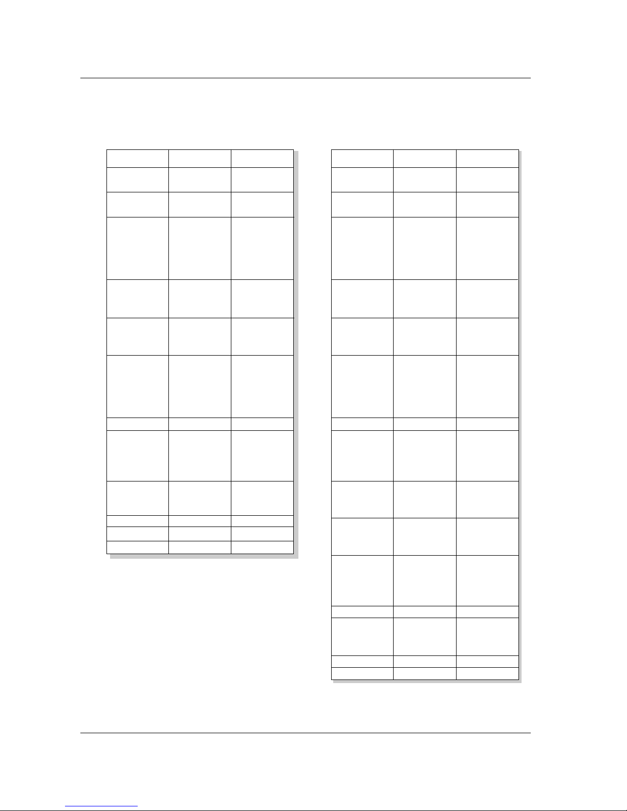
Installation
Displayable Monitor Specification
Displayable Monitor Specification
RGB / HDMI mode
Resolution
640x350
720x400
640x480
848x480
800x600
Horizontal
Frequency(KHz)
Vertical
Frequency(Hz)
852x480
832x624
1024x768
1152x864
1152x870
1280x960
1280x1024
70.09
85.08
70.08
85.03
59.94
66.66
72.80
75.00
85.00
60.00
70.00
75.00
60.00
70.00
75.00
56.25
60.31
72.18
75.00
85.06
74.55
60.00
70.06
75.02
85.00
60.05
70.01
75.00
75.06
60.02
60.02
31.468
37.861
31.469
37.927
31.469
35.000
37.861
37.500
43.269
31.500
37.799
39.375
31.500
37.799
39.375
35.156
37.879
48.077
46.875
53.674
49.725
48.363
56.476
60.023
68.677
54.348
63.995
67.500
68.681
60.023
63.981
RGB / HDMI mode
50PX3R series
42PX3RV series
Resolution
640x350
720x400
640x480
848x480
800x600
Horizontal
Frequency(KHz)
Vertical
Frequency(Hz)
852x480
832x624
1024x768
1360x768
1366x768
1152x864
1152x870
1280x960
1280x768
1280x1024
70.09
85.08
70.08
85.03
59.94
66.66
72.80
75.00
85.00
60.00
70.00
75.00
60.00
70.00
75.00
56.25 (RGB)
60.31
72.18
75.00
85.06
74.55
60.00
70.06
75.02
85.00
60.00
75.02
85.00
60.00
75.02
85.00
60.05
70.01
75.00
85.00
75.06
60.00
75.00
85.00
60.02
60.02
31.468
37.861
31.469
37.927
31.469
35.000
37.861
37.500
43.269
31.500
37.799
39.375
31.500
37.799
39.375
35.156
37.879
48.077
46.875
53.674
49.725
48.363
56.476
60.023
68.677
47.700
59.625
68.500
47.700
59.625
69.500
54.348
63.995
67.500
77.487
68.681
47.693
60.091
68.504
60.023
63.981

14 PLASMA TV
Installation
- HDMITM, the HDMI logo and High-Definition Multimedia Interface are trademarks or registered trademarks of HDMI Licensing.
- This set can receive the High-Definition Multimedia Interface (HDMI) or Input of Digital Visual Interface(DVI).
- This set supports HDCP (High-bandwidth Digital Contents Protection) Protocol for the set (480p, 720p, 1080i) modes.
- When you Connect with HDMI/DVI Source Devices (DVD Player or Set Top Box or PC) supporting Auto HDMI/DVI function,
automatically, support Plug & Play and then set the HDMI/DVI Source Devices (640 x 480p) (or 50PX3R series: 1280 x 720p).
After reading in HDMI/DVI Source Devices using Display Data Channel(DDC) Protocol, EDID stored in the set is used. If
HDMI/DVI Source Devices not supported Auto HDMI/DVI is been, the Resolution is set, manually.
- To get the best picture quality, adjust the DVD Player or Set Top Box output resolution to 640 x 480p (or 50PX3R series: 1280 x 720p).
- To get the best picture quality, adjust the PC graphics card to 640 x 480 (or 50PX3R series: 1024 x 768), 60Hz.
- When Source Devices have DVI Output Connector, you must connect audio with separated cable.(Refer to <How to connect>)
How to connect
1. When Source Devices (DVD Player or Set Top Box) support HDMI.
- If Source Devices have HDMI Output Connector, Source Devices connect to the set with HDMI Cable .(not supplied with the product).
- If Source Devices support Auto HDMI, automatically, Source Devices divert output resolution in 640x480p (or 50PX3R series:
1280 x 720p). But if not, resolution divert Manually Setting for reference Manual of Source Devices.
- To get the best picture quality, adjust the DVD Player or Set Top Box output resolution to 640x480p (or 50PX3R series: 1280 x
720p).
- Because HDMI sends Digital Video and Audio with one cable, need not especial Audio Cable for using HDMI Cable.
2. When Source Devices (DVD Player or Set Top Box) supports DVI.
- If Source Devices have DVI Output Connector, Source Devices connect to the set with HDMI to DVI Cable (not supplied with the
product).
- If Source Devices support Auto DVI, automatically, Source Devices divert output resolution in 640x480p (or 50PX3R series: 1280
x 720p). But if not, resolution divert Manually Setting for reference Manual of Source Devices.
- To get the best picture quality, adjust the DVD Player or Set Top Box output resolution to 640x480p (or 50PX3R series: 1280 x
720p).
- In this case, Audio use other cable. When Source Devices have Analog Audio Output Connector, RGB/DVI Audio Input of the set
connect to Audio Cable (not supplied with the product). And then you can listen to normal Audio.
3. When PC supports DVI.
- If PC have DVI Output Connector, Source Devices connect to the set with HDMI to DVI Cable (not supplied with the product).
- To get the best picture quality, adjust the PC graphics card to 640x480 (or 50PX3R series: 1024 x 768), 60Hz.
- Use the the set’s HDMI/DVI (VIDEO) for video connections, depending on your PC connector.
- If the graphics card on the PC does not output analog RGB and DVI simultaneously, connect only one of either RGB Input or
HDMI/DVI Input to display the PC on the set.
- If the graphics card on the PC does output analog RGB and DVI simultaneously, the set to either RGB Input or HDMI/DVI Input;
(the other mode is set to Plug and Play automatically by the set.)
- Then, make the corresponding audio connections. If using a sound card, adjust the PC sound as required.
- In this case, Audio use other cable. When PC (or sound card of PC) have Analog Audio Output Connector, RGB/DVI Audio Input
of the set connect to Analog Audio Cable (not supplied with the product). And then you can listen to normal Audio.
Owner’s Manual 15
Installation
How to use
1. Connect the HDMI/DVI Source Devices(DVD Player or Set Top Box or PC) and the set.
2. Turn on the display by pressing the POWER button on the set and HDMI/DVI Source Devices remote control.
3. Select HDMI/DVI Input source in Main Input option of PIP/DW menu.
4. Check the image on your set. There may be noise associated with the resolution, vertical pattern, contrast or brightness in
HDMI/DVI Source Devices. If noise is present, change the HDMI/DVI Source Devices to another resolution, change the refresh
rate or adjust the brightness and contrast on the menu until the picture is clear. If the refresh rate of the PC graphics card can not
changed, change the PC graphics card or consult the manufacturer of the PC graphics card.
Notes:
- Depending on the graphics card, DOS mode may not work if you use a HDMI to DVI Cable.
- Avoid keeping a fixed image on the set screen for a long period of time. The fixed image may become permanently imprinted on
the screen. Use the Orbiter screen saver when possible.
- When Source Devices connected HDMI/DVI Input, output PC Resolution(VGA, SVGA, XGA), Position, Size may not fit to Screen.
As shown the lower picture, press the MENU button to adjust the screen Position of the set and contact an PC graphics card service center.
- When Source Devices connected HDMI/DVI Input output the set Resolution(480p, 720p, 1080i), the set Display fit EIA/CEA-861B Specification to Screen. If not, refer to the Manual of HDMI/DVI Source Devices or contact your service center.
- In case HDMI/DVI Source Devices is not connected Cable or poor cable connection, "No Signal" OSD display in HDMI/DVI Input.
And In case of Video Resolution not supported the set output in HDMI/DVI Source Devices, "No Signal" OSD display. Refer to the
Manual of HDMI/DVI Source Devices or contact your service center.
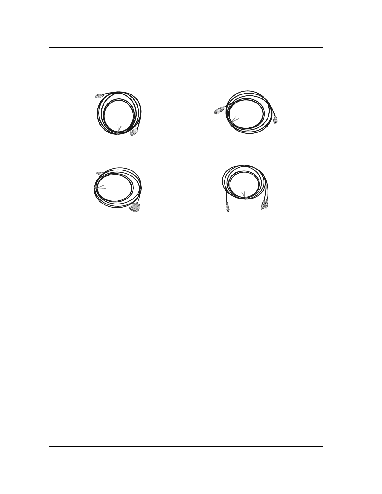
Reference
Cable sample
HDMI to DVI Cable
(not supplied with the product)
Analog Audio Cable (RCA type)
(not supplied with the product)
Analog Audio Cable (Stereo to RCA type)
(not supplied with the product)
HDMI Cable
(not supplied with the product)
 Loading...