

Page 1
OMEGATMDesktop Recording Studio
Owner’s Manual
Page 2
WARNING FOR YOUR PROTECTION
PLEASE READ THE FOLLOWING:
KEEP THESE INSTRUCTIONS
HEED ALL WARNINGS
FOLLOW ALL INSTRUCTIONS
DO NOT USE THIS APPARATUS NEAR WATER
CLEAN ONLY WITH A DRY CLOTH.
DO NO
T BLOCK ANY OF THE VENTILATION OPENINGS.
INSTALL IN ACCORDANCE WITH THE MANUFACTURER’S
INSTR
UCTIONS.
DO NOT INSTALL NEAR ANY HEAT SOURCES SUCH AS
RADIATORS, HEAT REGISTERS, STOVES, OR OTHER
APP
ARATUS (INCLUDING AMPLIFIERS) THAT PRODUCE
HEAT.
ONLY USE ATTACHMENTS/ACCESSORIES SPECIFIED BY
THE MANUFACTURER.
UNPLUG THIS APPARATUS DURING LIGHTNING STORMS
OR WHEN UNUSED FOR LONG PERIODS OF TIME.
Do not defeat the safety purpose of the polarized or grounding-type plug. A polarized plug has two blades with one wider
than the other. A grounding type plug has two blades and a
third grounding prong. The wide blade or third prong are
provided for your safety. If the provided plug does not fit your
outlet, consult an electrician for replacement of the obsolete
outlet.
Protect the power cord from being walked on or pinched
particularly at plugs, convenience receptacles, and the point
where they exit from the apparatus.
Use only with the cart stand,
tripod bracket, or table specified
by the manufacture, or sold with the apparatus. When a cart is
used, use caution when moving the cart/apparatus combination
to avoid injury fr
om tip-over.
Refer all servicing to to qualified service personnel. Servicing
is required when the apparatus has been damaged in any way,
such as power-supply cord or plug is damaged, liquid has been
spilled or objects have fallen into the apparatus, the apparatus
has been exposed to rain or moisture, does not operate
normally, or has been dropped.
POWER ON/OFF SWITCH: For products provided with a
power switch, the power switch DOES NOT break the
connection from the mains.
MAINS DISCONNECT: The plug shall remain readily operable.
For rack-mount or installation where plug is not accessible, an
all-pole mains switch with a contact separation of at least 3 mm
in each pole shall be incorporated into the electrical installation
of the rack or building.
FOR UNITS EQUIPPED WITH EXTERNALLY ACCESSIBLE
FUSE RECEPTACLE: Replace fuse with same type and rating
only.
MULTIPLE-INPUT VOLTAGE:This equipment may require the
use of a different line cord, attachment plug, or both, depending on the available power source at installation. Connect this
equipment only to the power source indicated on the
equipment rear panel. To reduce the risk of fire or electric
shock, refer servicing to qualified service personnel or equivalent.
SAFETY INSTRUCTIONS
NOTICE FOR CUSTOMERS IF YOUR UNIT IS EQUIPPED
WITH A POWER CORD.
WARNING: THIS APPLIANCE MUSTBE EARTHED.
The cores in the mains lead are coloured in accordance with
the following code:
GREEN and YELLOW - Earth BLUE - Neutral BROWN - Live
As colours of the cores in the mains lead of this appliance may
not correspond with the coloured markings identifying the terminals in your plug, proceed as follows:
• The core which is coloured green and yellow must be
connected to the terminal in the plug marked with the
letter E, or with the earth symbol, or coloured green,or
green and yellow.
• The core which is coloured blue must be connected to
the terminal marked N or coloured black.
• The core which is coloured brown must be connected to
the terminal marked L or coloured red.
This equipment may require the use of a different line cord,
attachment plug, or both, depending on the available power
source at installation. If the attachment plug needs to be
changed, refer servicing to qualified service personnel who
should refer to the table below. The green/yellow wire shall be
connected directly to the units chassis.
WARNING:If the ground is defeated, certain fault conditions in
the unit or in the system to which it is connected can result in
full line voltage between chassis and earth ground. Severe injury
or death can then result if the chassis and earth ground are
touched simultaneously.
The symbols shown above are internationally accepted
symbols that warn of potential hazards with electrical
products. The lightning flash with arrowpoint in an equilateral triangle means that there are dangerous voltages
present within the unit. The exclamation point in an equilateral triangle indicates that it is necessary for the user to
refer to the owner’s manual.
These symbols warn that there are no user serviceable
parts inside the unit. Do not open the unit. Do not
attempt to service the unit yourself. Refer all servicing to
qualified personnel. Opening the chassis for any reason
will void the manufacturer’s warranty. Do not get the unit
wet. If liquid is spilled on the unit, shut it off immediately
and take it to a dealer for service. Disconnect the unit
during storms to prevent damage.
IMPORTANT SAFETY INSTRUCTIONS
CAUTION
RISK OF ELECTRIC SHOCK
ATTENTION:
WARNING:
SHOCK DO NOT EXPOSE THIS EQUIPMENT TO RAIN OR MOISTURE
CONDUCTOR
L
N
E
DO NOT OPEN
RISQUE DE CHOC ELECTRIQUE - NE PAS OUVRIR
TO REDUCE THE RISK OF FIRE OR ELECTRIC
WIRE COLOR
Normal Alt
BROWN
LIVE
NEUTRAL
EARTH GND
GREEN/YEL
BLUE
BLACK
WHITE
GREEN
Page 3
U.K. MAINS PLUG WARNING
A molded mains plug that has been
cut off from the cord is unsafe.
Discard the mains plug at a
suitable disposal facility.
NEVER UNDER ANY
CIRCUMSTANCES SHOULD YOU
INSERT A DAMAGED OR CUT
MAINS PLUG INTO A 13 AMP
POWER SOCKET.
Do not use the mains plug without
the fuse cover in place.
Replacement fuse covers can be
obtained from your local retailer.
Replacement fuses are 13 amps
and MUST be ASTA approved to
BS1362.
IMPORTANT SAFETY INSTRUCTIONS
ELECTROMAGNETIC
COMPATIBILITY
This unit conforms to the Product
Specifications noted on the Declaration
of Conformity. Operation is subject to
the following two conditions:
• this device may not cause harmful
interference, and
• this device must accept any
interference received, including
interference that may cause
undesired operation.
Operation of this unit within significant
electromagnetic fields should be avoided.
• use only shielded interconnecting
cables.
DECLARATION OF
CONFORMITY
Manufacturer’s Name: Lexicon Professional
Manufacturer’s Address: 8760 S. Sandy Pkwy.
Sandy, UT 84070, USA
Declares that the product:
Product name: Lexicon Omega
TM
Note: Product name may be
suffixed by the letters-EU.
Product option: all (requires Class II
power adapter that con
forms to the
requirements of
EN60065,
EN60742, or equivalent.)
Conforms to the following Product
Specifications:
Safety: IEC 60065 (1998)
EMC: EN 55013 (1990)
EN 55020 (1991)
Supplementary Information:
The product herewith complies with the
requirements of the Low Voltage Directive
72/23/EEC and the EMC Directive 89/336/EEC
as amended by Directive 93/68/EEC.
Vice-President of
Engineering
8760 S. Sandy Parkway
Sandy, Utah 84070, USA
Date: September 2003
European Contact: Your local Lexicon
Professional Sales and
Service Office or
Harman Music Group
8760 S. Sandy Pkwy.
Sandy, UT 84070 USA
Ph: (801) 566-8800
Fax: (801) 568-7583
Page 4

SERVICE INFO
If you require technical support,
contact Lexicon Professional Customer
Service. Be prepared to accurately
describe the problem. Know the serial
number of your unit, it is printed on a
sticker attached to the rear panel. If
you have not already taken the time
to fill out your warranty registration
card and send it in, please do so now.
Before you return a product to the
factory for service, we recommend
you refer to the manual. Make sure
you have correctly followed
installation steps and operation
procedures. If you are still unable to
solve a problem, contact our
Customer Service Department at
(801) 568-7660 for consultation. If
you need to return a product to the
factory for service, you MUST
contact Customer Service to obtain
a Return Authorization Number.
No returned products will be
accepted at the factory without a
Return Authorization Number.
Please refer to the Warranty
information on the following page,
which extends to the first end-user.
After expiration of the warranty, a
reasonable charge will be made for
parts, labor, and packing if you
choose to use the factory service
facility. In all cases, you are
responsible for transportation
charges to the factory. Lexicon
Professional will pay return shipping
if the unit is still under warranty.
Use the original packing material if it
is available. Mark the package with
the name of the shipper and with
these words in red:
DELICATE INSTRUMENT, FRAGILE!
Insure the package properly. Ship
prepaid,not collect. Do not ship
parcel post.
WARRANTY
This warranty is valid only for the
original purchaser and only in the
United States.
1. The warranty registration card that
accompanies this product must be
mailed within 30 days after purchase
date to validate this warranty.
Proof-of-purchase is considered to
be the burden of the consumer.
2. Lexicon Professional warrants this
product, when bought and used
solely within the U.S., to be free
from defects in materials and
workmanship under normal use
and service.
3. Lexicon Professional’s liability under
this warranty is limited to repairing or,
at our discretion, replacing defective
materials that show evidence of
defect, provided the product is
returned to Lexicon professional WITH
RETURN AUTHORIZATION from the
factory, where all parts and labor will
be covered up to a period of 1 year
.
A Return Authorization number must
be obtained from Lexicon
Professional by telephone. The
company shall not be liable for any
consequential damage as a result of
the product's use in any circuit or
assembly.
4. Lexicon Professional reserves the
right to make changes in design or
make additions to or improvements
upon this product without incurring
any obligation to install the same
additions or improvements on
products previously manufactured.
5. The foregoing is in lieu of all other
warranties, expressed or implied, and
Lexicon Professional neither assumes
nor authorizes any person to assume
on its behalf any obligation or liability
in connection with the sale of this
product. In no event shall Lexicon
Professional or its dealers be liable for
special or consequential damages or
from any delay in the performance
of this warranty due to causes
beyond their control.
OMEGA
TM
Service Info/Warranty
Page 5

Lexicon Professional
®
Table of Contents
Introduction . . . . . . . . . . . . . . . . . . . . . . . . . . . . . . . . . . . . . . . . . . . . . . . . . . . . . 1
Features . . . . . . . . . . . . . . . . . . . . . . . . . . . . . . . . . . . . . . . . . . . . . . . . . . . . . . . . 1
Unpacking the OmegaTM. . . . . . . . . . . . . . . . . . . . . . . . . . . . . . . . . . . . . . . . . . . 2
System Requirements. . . . . . . . . . . . . . . . . . . . . . . . . . . . . . . . . . . . . . . . . . . . . . 2
The Front Panel. . . . . . . . . . . . . . . . . . . . . . . . . . . . . . . . . . . . . . . . . . . . . . . . . . . 3
The Rear Panel . . . . . . . . . . . . . . . . . . . . . . . . . . . . . . . . . . . . . . . . . . . . . . . . . . . 5
Making Connections . . . . . . . . . . . . . . . . . . . . . . . . . . . . . . . . . . . . . . . . . . . . . . 7
Monitoring Audio . . . . . . . . . . . . . . . . . . . . . . . . . . . . . . . . . . . . . . . . . . . . . . . . . 7
Recording Audio . . . . . . . . . . . . . . . . . . . . . . . . . . . . . . . . . . . . . . . . . . . . . . . . . 7
Mixdown of Audio . . . . . . . . . . . . . . . . . . . . . . . . . . . . . . . . . . . . . . . . . . . . . . . . 8
Connections Diagram . . . . . . . . . . . . . . . . . . . . . . . . . . . . . . . . . . . . . . . . . . . . . 9
Connections Diagram . . . . . . . . . . . . . . . . . . . . . . . . . . . . . . . . . . . . . . . . . . . . . 9
Software Setup . . . . . . . . . . . . . . . . . . . . . . . . . . . . . . . . . . . . . . . . . . . . . . . . . . 10
Windows
®
Software Setup . . . . . . . . . . . . . . . . . . . . . . . . . . . . . . . . . . . . . . . . . 10
Macintosh®Software Setup . . . . . . . . . . . . . . . . . . . . . . . . . . . . . . . . . . . . . . . . 15
Signal Routing Diagram . . . . . . . . . . . . . . . . . . . . . . . . . . . . . . . . . . . . . . . . . . . 16
Specifications . . . . . . . . . . . . . . . . . . . . . . . . . . . . . . . . . . . . . . . . . . . . . . . . . . 17
Page 6

INTRODUCTION
Congratulations on your purchase of
the Lexicon OMEGA™ desktop
recording studio. The Lexicon OMEGA
is a complete, USB-connected
recording solution. Comprised of an
intuitive I/O unit and multi-track
recording software, the OMEGA works
in conjunction with your computer to
give you a compact, professionalquality audio production system and
provides all the tools necessary for
expert results. Complementing the
OMEGA’s analog and digital I/O, Pro
Tracks Plus
TM
software for PC’s offers
integrated multi-track recording,
editing and mixing of 32 audio tracks,
unlimited MIDI tracks, DXi soft synth
support, and an array of additional
features. BIAS
®
DeckTM3.5 SE software
for Mac’s offers integrated multi-track
recording, editing and mixing of 64
audio tracks, up to 99 virtual tracks and
numerous additional features. Also
included with the OMEGA is Lexicon’s
Pantheon™ reverb plug-in. Lexicon
reverbs have been used on
professional recordings for over thirty
years.
FEATURES
The Omega™ desktop studio provides
the following:
• 6 channels of 24-bit streaming
audio via USB (4 record, 2
playback)
• 7 analog audio inputs
• 2 - XLR mic inputs with
extremely low noise dbx
®
preamps
• 20 dB Mic Pad
• 4 - 1/4” analog RF filtered TRS
active-balanced line inputs
• 1 - 1/4” ultra-Hi-Z analog
instrument input
• 2 - 1/4” analog TRS servobalanced, active line outputs
• S/PDIF coaxial digital input and
output
• 1/4” TRS insert on each mic
input
• MIDI In and Out
• +48V phantom power
• 24-bit A/D and D/A converters,
supporting sample rates of 44.1
kHz and 48 kHz
• Zero-latency analog record
monitoring with adjustable
balance between input and
playback
• Stereo and Mono input source
monitoring
• Power supply included
IntroductionOMEGA
TM
1
Page 7

UNPACKING THE OMEGA
The Omega™is shipped in one carton,
containing the interface hardware, Pro
Tracks Plus
™
software for Windows®-
based systems, and BIAS
®
Deck 3.5 SE
™
software for Mac®-based systems.
After unpacking, save all the
packaging materials in case you ever
have to ship the unit. Thoroughly
inspect the Omega and packing
materials for signs of damage. Report
any shipment damage to the carrier
that delivered the product or dealer
from whom you purchased the
product at once.
The following items are included:
• Omega desktop audio
interface
• Installer CD-Rom containing
Pro Tracks Plus
™
Recording
Software and the Lexicon
Pantheon
™
Reverb Plug-in for
Windows
• Installer CD-Rom containing
BIAS
®
Deck 3.5 SE™Recording
Software, BIAS
®
Deck 3.5 SE
™
Owner’s Manual, and the
Lexicon Pantheon
™
Reverb
Plug-in for Mac
• Installer CD-Rom containing
Windows XP/2000 USB drivers
• USB connector cable
• This Owner’s Manual
• Pro Tracks Plus
™
Owner’s
Manual
• Lexicon Pantheon
TM
Reverb
Plug-in User’s Guide
• Pro Track Plus
™
Shortcut Guide
• Omega Software Installation
Guide
• Lexicon Professional warranty
registration card
SYSTEM REQUIREMENTS
WINDOWS
®
• Pentium®III 500 MHz
(1.2 GHz recommended)
• Windows 2000 or Windows XP
• 128 MB RAM
(512 MB recommended)
• 100 MB of available hard disk
space
• EIDE/Ultra DMA 7200RPM hard
disk type or better
MACINTOSH
®
• Power PC®, G4 Processor
(450 MHz or faster)
• Mac OS X version 10.2.8 or
later
• 128 MB RAM minimum
(512MB recommended)
• 20 MB available hard disk
space
• 18 ms hard drive
(average speed time) or faster
• QuickTime
™
3.0 or later
Lexicon Professional
®
Introduction
2
Page 8
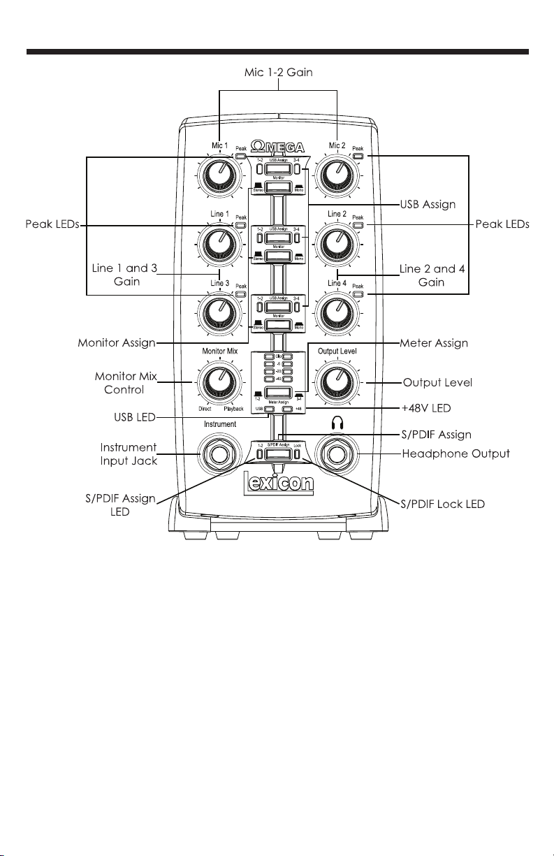
THE FRONT PANEL
The Omega’s front panel offers the
following features:
• Mic 1-2 Gain
These knobs adjust the input gain levels
of the Mic 1 and Mic 2 inputs.
• Line 1-4 Gain
These knobs adjust the input gain levels
of the Line 1 through Line 4 inputs.
• Peak LEDs
These LEDs will light when the input
signal is within 5dB of analog clipping. If
the Peak LEDs flicker occasionally, the
signal is approaching clipping levels,
but does not necessarily indicate
distortion or actual clipping.
• USB Assign
These buttons select which USB audio
bus (USB 1-2 or 3-4) that signal is
streaming up to the computer on.
• Monitor Assign
These buttons select whether analog
audio sources are heard in stereo or
mono. Audio sources plugged into the
Omega are placed accordingly in the
analog stereo field. Odd numbered
inputs are routed to the left channel
and even numbered inputs are routed
to the right channel.
The Front PanelOMEGA
TM
3
V
Page 9

• Monitor Mix Control
The Omega gives you the ability to
monitor your analog input signals while
recording without the delay incurred by
A/D/A converters and computer
recording latency. This zero-latency
analog monitoring is controlled by the
Monitor Mix knob, which you can use to
blend and adjust the ratio between
OMEGA analog inputs and computer
audio playback. Any signal coming in
on the S/PDIF input is converted to
analog and sent to the mix control so
that you can monitor this input directly
just like an analog input. To listen to just
the source input signal, turn the Mix
knob fully left to Direct. The Output
from the Mix control is routed directly to
the Line and Headphone outputs. This
ability to blend and control the relative
levels of computer audio playback and
latency-free live analog inputs is
effective when overdubbing.
• Output Level
This knob controls the overall output
level of the Omega’s Line and
Headphone outputs.
• Meter Assign
This switch assigns which signals (signals
assigned to USB 1-2 bus or USB 3-4 bus)
are being monitored by the Omega’s
meter ladder. This LED Meter shows the
signal level into the A/D converters.
When the Meter’s Clip LEDs light,
analog input signals are clipping the
A/D converter. Adjust the Mic and Line
gain knobs so that the -6 dB yellow LED
only lights occasionally.
• USB LED
The USB LED indicates that the Omega
is communicating with your computer
via USB and audio and MIDI signals can
pass in and out of the system. If the USB
LED is blinking, the Omega is not
communicating with your computer.
• +48V LED
This LED indicates that 48 Volt phantom
power is active on the Mic 1 and 2
inputs. These inputs provide phantom
power for condenser microphones that
require it to operate. Phantom Power is
activated by the switch labeled +48V
Phantom on the bottom of the rear
panel of the Omega.
• S/PDIF Assign
This button assigns the S/PDIF digital
input to the USB 1-2 audio bus. When
S/PDIF is enabled, only digital audio can
use the USB 1-2 bus and any analog
inputs that were assigned to USB 1-2 are
disabled. Analog inputs can still be
assigned to the USB 3-4 bus while the
S/PDIF Assign is enabled, allowing both
digital and analog audio to be
recorded simultaneously.
• S/PDIF Assign LED
This LED lights when the S/PDIF input is
assigned to the USB 1-2 bus.
• S/PDIF Lock LED
The LED lights when the S/PDIF input has
locked in with the Omega. If this LED is
not lit, digital signal can not be
received from external devices via the
S/PDIF input.
• Headphone Output
The Headphone Output
accommodates stereo headphones
with a 1/4” stereo plug.
• Instrument Input Jack
This 1/4” jack accepts unbalanced
instrument sources such as electric
guitar, acoustic guitar with a pickup,
and electric bass. The input gain is
adjusted using the Line 3 knob on the
front panel respectively. When an
instrument is plugged in, it disables the
Line 3 audio input.
Lexicon Professional
®
The Front Panel
4
Page 10
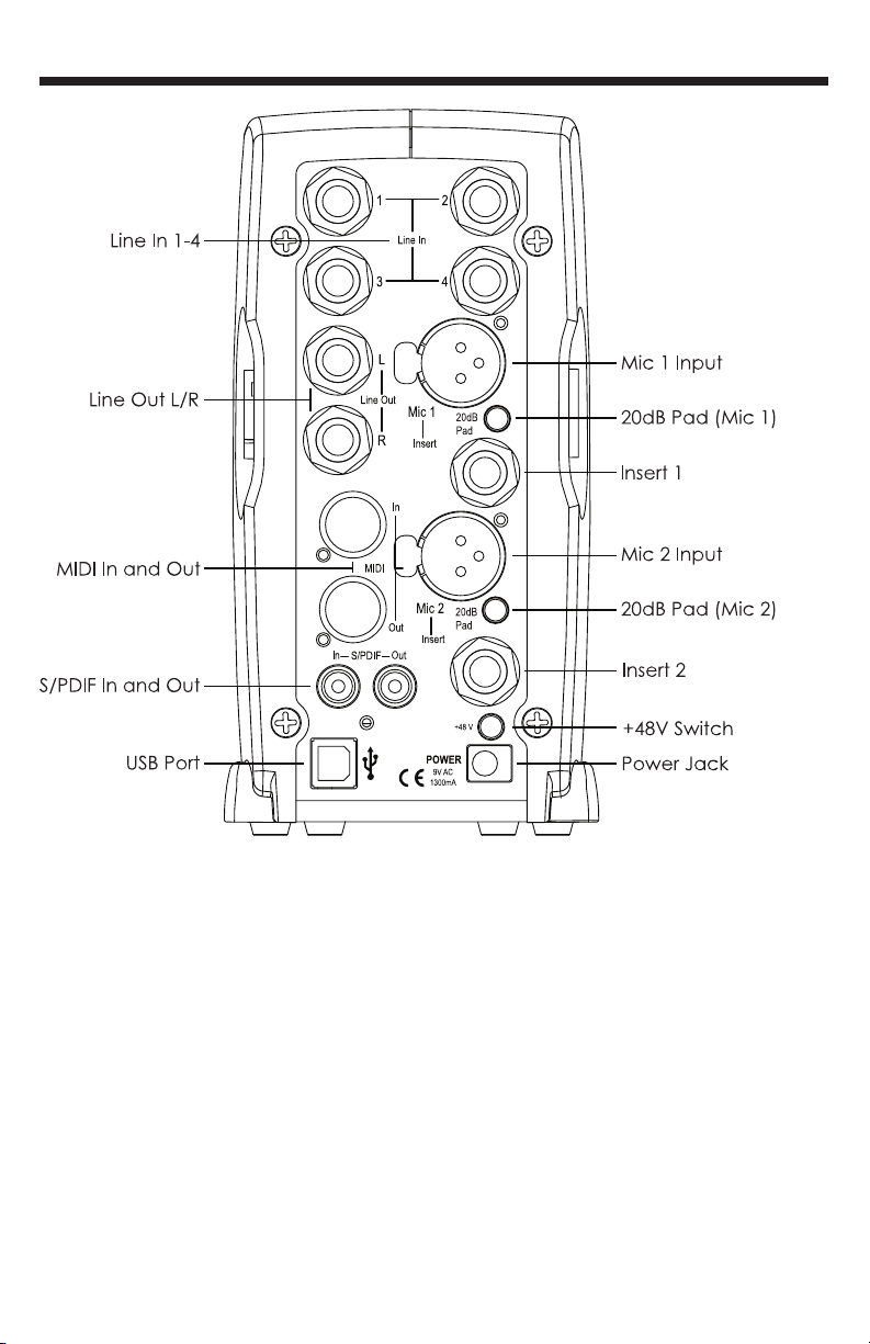
THE REAR PANEL
The OMEGA’s rear panel offers the
following features:
• Line In 1-4
These 1/4” inputs can accept both
balanced and unbalanced audio
sources. The input gain is adjusted
using the Line 1-4 knobs on the front
panel respectively.
• Line Out L/R
These outputs support balanced TRS or
unbalanced TS 1/4” connections. These
outputs can be connected to a mixing
board, power amplifier, or another line
level input.
• Mic 1-2 Inputs
These balanced XLR inputs feature high
quality dbx
®
mic preamps designed
specifically for microphone use. The
input gain is adjusted using the Mic 1-2
knobs on the front panel respectively.
• -20dB Pad
The -20dB pad is a resistive attenuator
that drops the level coming from the
mic input jacks. Its purpose is to give
you a way of preventing overload of
the preamp when incoming signals
become excessive. Another purpose is
to change the preamp’s mic input into
a line input. The Omega provides a
pad of -20dB. This means when the
The Rear Panel
OMEGA
TM
5
Page 11

Lexicon Professional
®
pad is on, the net gain of the preamp
is 20dB lower than normal.
• Insert 1-2
Each mic input is equipped with a TRS
insert point. Inserts provide a send and
return of the input channel’s signal
directly after the mic preamp and
before the A/D converter. You can
insert any line level analog processors
such as compressor or equalizer for
pre-processing of the mic signal before
it is recorded. The tip is send and the
ring is return.
• S/PDIF In and Out
The S/PDIF in and out ports are
unbalanced phono (RCA) connectors
that transmit and receive either 16-bit or
24-bit two-channel audio stream.
S/PDIF is used in many professional and
consumer CD and digital audio
recorders. It is recommended to use
75-Ohm coaxial cable for S/PDIF
transfers and keep the cable length to
a maximum of 10 meters to minimize
interference and data dropout. The
S/PDIF output only sends the stereo
signal that is returned from the
computer. Thus it is not affected by the
setting of the Mix control.
• +48V Switch
This switches on the phantom power to
the Mic 1 and Mic 2 inputs. Dynamic
microphones do not require phantom
power to operate, but are not harmed
by it. Most condenser microphones do
require phantom power to operate. If
you are unsure about the phantom
power requirements for your
microphone, consult your microphone’s
documentation or contact the
manufacturer.
• USB Port
The USB Port is used to connect the
Omega to your computer. A standard
USB cable is included. The Omega is
compatible with USB 2.0 ports, but the
USB 2.0 bus will switch to the slower USB
v1.1 speed to work with the Omega.
• MIDI In and Out
The MIDI jacks provide MIDI input and
MIDI output to and from your computer.
Connect your MIDI keyboards, sound
modules, and external controllers here.
• Power Jack
Use only the supplied PS0913-B power
supply to power the Omega.
The Rear Panel
6
Page 12

MAKING CONNECTIONS
The OMEGA is both an 8 x 4 x 2 mixer
and USB audio interface that can used
in a variety of audio setups. This section
describes how to make basic
connections for the following
applications:
• Monitoring Audio
• Recording Audio
• Connecting a Recorder for
Mixdown
Monitoring Audio
Omega Line Outputs play the audio
that is routed in Pro Tracks Plus™ or
BIAS Deck SE
TM
to Analog Outputs 1-2,
and can provide left and right outputs
to a two-track deck for mixdown, or to
another stereo destination.
Omega Line Outputs offer 24-bit
digital-to-analog converters capable
of nominal output of +4 dBu/+2 dBV
(balanced/unbalanced signal). The
connectors are TRS jacks; unbalanced
TS connectors are also supported.
Connecting headphones:
1. Connect headphones to the
Headphone jack located on
the front panel of the Omega.
The Headphone Output
accepts a 1/4” TRS connector.
2. Adjust headphone volume via
the Output Level knob.
Connecting to monitor speakers with a
power amp or self-powered monitor
speakers:
1. Using 1/4” cables, connect the
Line Outputs on the rear panel
of the Omega to the
appropriate inputs on your
mixer, power amp, or powered
speakers.
2. Adjust headphone volume via
the Output Level knob.
Connecting to a home stereo:
1. Using 1/4” cables, connect the
Line Outputs on the rear panel
of the Omega to the
appropriate inputs on your
stereo.
Recording Audio
Digital and analog audio sources can
be connected directly to the Omega.
Analog Audio:
Analog audio signals are output by
microphones, synthesizers, mixers, and
instruments with magnetic pickups.
Of these sources, microphones and
magnetic pickup instruments output
the quietest signals, and generally
require the most amplification.
Keyboards, preamps, and mixers
output “line level” audio, which varies
with each device between the -10 dBV
and +4 dBu standards.
To connect an analog audio source:
1. Plug an XLR or TRS cable
directly into the desired
Mic/Line Input on the Omega.
The Mic Inputs accept XLR
connectors, the Line Inputs
accept TRS connectors.
OMEGA
TM
7
Making Connections
Page 13

To activate Phantom Power:
If your microphone requires phantom
power, first make sure the microphone
is connected, then press the Phantom
Power switch (labeled +48V). The +48V
LED on the front panel indicates the
phantom power is active. If your mics
don’t need phantom power, it is best
to turn it off.
Using the Analog Inserts:
The analog inserts require a 1/4” TRS to
2 x 1/4” TS adapter cable. The signal
from the tip should be routed to the
input of your outboard processor and
the output of your processor should be
routed to the ring.
Digital Audio:
Digital audio represents analog
waveforms using thousands of digital
samples of the analog waveforms
each second. All audio on your hard
drive in a Pro Tracks Plus
TM
or Bias Deck
SE
TM
session is digital audio.
The Omega provides digital inputs and
outputs for S/PDIF format digital audio.
Connecting a S/PDIF device to the
Omega:
1. Use two 75 Ohm coaxial
cables with male RCA
connectors on both ends.
2. Connect the device’s S/PDIF
output to the Omega’s S/PDIF
input jack, and the device’s
S/PDIF input to the Omega’s
S/PDIF output jack.
Connecting a Recorder for
Mixdown
After you record and mix your sessions
in either Pro Tracks Plus
TM
or Bias Deck
SE
TM
, you may want to mix them down
to a DAT, audio cassette, or other
stereo 2-track recording device.
Connecting an Analog Deck:
Connect your recorder (cassette deck
or other analog device) to the Line
Outputs on the back of the Omega.
The Left and Right Line Outputs should
be routed to the left and right inputs,
respectively, on your recorder. These
outputs are TRS jacks. You may need
adapter cables if your mixdown deck
has RCA jack inputs.
Connecting a Digital Deck:
If you have a DAT or other device that
accepts S/PDIF connections, connect it
to the S/PDIF In and S/PDIF Out RCA
jacks on the back of the Omega.
Making Connections
8
Lexicon Professional
®
Page 14

CONNECTIONS DIAGRAM
OMEGA
TM
9
Making Connections
Page 15

Software Setup
10
Lexicon Professional
®
WINDOWS®SOFTWARE
SETUP
You must consult the Software
Installation Guide packaged with the
software CD-ROMs inside the Omega
box to ensure the successful installation
of the recording software and USB
drivers.
If you haven’t already installed the
your software, please do so before
continuing on to the next section.
Also, consider the following information
as it pertains to your computer’s
operating system prior to installing the
USB drivers.
WINDOWS XP
Windows XP-based systems. You must
install the USB drivers after you’ve
made the connection between your
computer’s USB port and the USB port
of the Omega.
WINDOWS 2000
Windows 2000-based systems must
have the USB drivers installed before
making the connection between your
computer’s USB port and the USB port
on the Omega.
Page 16

DRIVER CONFIGURATION
Here are a couple USB Driver
configuration notes that we’d like to
draw your attention to once you’ve
successfully completed the software
installation.
Open Pro Tracks Plus
Tm
and follow these
steps:
WINDOWS®XP/2000
Go to Options>Audio. Click on the
Drivers Tab. Selec the Lexicon drivers
as shown below. This is a typical setup.
Make sure that only the Lexicon Win
USB drivers are highlighted.
OMEGA
TM
11
Software Setup
Page 17

WINDOWS®XP (16 & 24 bit audio)
WINDOWS®2000 (16 bit audio)
To set the drivers for Windows XP
(16 and 24 bit depths) and Windows
2000 (16 bit depth), Go to
Options>Audio. Click the Advanced
tab. Select WDK/KS in the Driver Mode
field under Playback and Recording
section as shown below.
Lexicon Professional
®
Software Setup
12
Page 18

WINDOWS®2000 (24 bit audio)
To set the drivers for Windows 2000
(24 bit depth), go to Options>Audio.
Click the Advanced tab. Select MME
(32-bit) in the Driver Mode field under
Playback and Recording
section as shown below.
Software Setup
OMEGA
TM
13
Page 19

WINDOWS®2000 and WINDOWS®XP
PLAYBACK AND RECORD TIMING
To set the Playback Timing and the
Record Timing go to Options>Audio.
Click the General tab. Select Lexicon
Win USB 1-2 In/Out in the Playback
Timing Master field and in the Record
Timing Master field. Also, select your
desired bit depth in the Audio Driver Bit
Depth field and in the File Bit Depth
field. (24 bit is shown below)
Lexicon Professional
®
Software Setup
14
Page 20

MACINTOSH®SOFTWARE
SETUP
You must consult the Software
Installation Guide packaged with the
software CD-ROMs inside the Omega
box to ensure the successful installation
of the recording software and USB
setup.
If you haven’t already installed the
your software, please do so before
continuing on to the next section.
Mac OS
A USB device must initialize itself with
the host computer to operate
correctly. The Omega Studio
comprises several devices (audio and
MIDI) and each of those must be
initialized. Some Apple
®
Mac
computers will not recognize all of
these devices if the Omega Studio is
powered on (and connected to the
USB port) before the computer is
turned on. The simplest way to avoid
problems is to either turn on the
Omega Studio or connect it to the USB
port after the computer is booted.
However, there is a way to fore a
reinitialization after the computer is
running.
1. Make sure you close any
applications which are using
the Omega Studio.
2. Press the Mic 1-2 USB Assign
button and the Line 3-4 USB
Assign button at the same time
and then release them
simultaneously. The blue USB
light will flash and after three
seconds the Omega Studio will
be properly initialized.
Software Setup
OMEGA
TM
15
Page 21

Lexicon Professional
®
Signal Routing Diagram
16
Page 22

SPECIFICATIONS
Specifications
OMEGA
TM
17
Microphone Inputs: (2) Female XLR Pin 2 Hot
Input Impedance: 600 Ohms balanced
Phantom Power: +48 Volt
EIN: -118dB @ 51dB gain (150 Ohm source impedance) -120 dB A-
weighted
Maximum Input Level: +18 dBu (150 Ohm source impedance)
Frequency Response: +0, -0.2 dB 20 Hz - 20 kHz, ref. 1 kHz
THD+N: <.005%, 20 Hz - 20 kHz
Insert Inputs: (2) 1/4” TRS
Send Level (tip): +19 dBu maximum
Maximum Return Level (ring): +19 dBu maximum
Line Inputs: (4) 1/4” TRS balanced or unbalanced
Input Impedance: 20 kOhm balanced, 10 kOhm unbalanced
Maximum Input Level: +22 dBu (40 Ohm source impedance)
Frequency Response: +0, -0.2 dB 20 Hz - 20 kHz, ref. 1kHz
THD+N: <.012% A/D, 20 Hz - 20 kHz, <.012% A/D/A, 20 Hz - 20 kHz
Instrument Input: (1) 1/4” mono jack
Input Impedance: 1 MOhm unbalanced
Maximum Input Level: +19 dBu
Frequency Response: +0, -0.25 dB 20 Hz - 20 kHz, ref. 1 kHz
THD+N: <.0125% A/D
Crosstalk: <-74dB any input or output to any recording channel, 20 Hz-20 kHz
<-95dB at 1 kHz typical
Line Outputs: (2) 1/4” TRS balanced or unbalanced
Level: +19 dBu maximum
Impedance: 110 Ohms
Headphone Output: (1) 1/4” stereo jack
100 mW per channel at 50 Ohms
MIDI Interface: 5 pin DIN connectors for MIDI in and MIDI out
Digital Audio Input: Coaxial RCA (S/PDIF format)
Digital Audio Output: Coaxial RCA (S/PDIF format) always transmits the audio data from
the USB stream
D/A and A/D Conversion
Sample Rate: 44.1 kHz or 48 kHz (determined by computer application)
Dynamic Range:
A/D >101 dB typical, unweighted, 20 Hz - 20 kHz
>104 dB typical, A-weighted, 20 Hz - 20 kHz
D/A >107 dB typical, unweighted, 20 Hz - 20 kHz
>109 dB typical, A-weighted, 20 Hz - 20 kHz
A/D/A >100 dB typical, unweighted, 20 Hz - 20 kHz
>103 dB typical, A-weighted, 20 Hz - 20 kHz
Analog Path: >115 dB typical, unweighted, 20 Hz - 20 kHz
>118 dB typical, A-weighted, 20 Hz - 20 kHz
USB Type B Socket: Version 1.1, Version 1.1 hubs are not supported
Power Requirements: PS0913-B adapter supplied
Dimensions: 4.625”W x 7.25”H x 7.75” D (118mm x 184mm x 197mm)
Weight: 2.65 lbs.
Lexicon engineers are constantly working to improve the quality of our products. Specifications are, therefore subject to
change without notice.
Page 23

18-0233
8760 South Sandy Parkway
Sandy, Utah 84070 U.S.A.
Phone: (801)-568-7660
Fax: (801)-568-7662
Questions or comments?
Email us at: customer@lexiconpro.com
or visit our World Wide Web home page
at:
www.lexiconpro.com
Copyright 2003 Lexicon Professional
®
A Harman International Company
 Loading...