

Page 1

Owner's Manual
480L
Digital Effects System
Page 2
Important Safety Instructions
Save these instructions for later use.
Follow all instructions and warnings marked on the unit.
Always use with the correct line voltage. Refer to the manufacturer's operating instructions for power requirements. Be advised that different
operating voltages may require the use of a different line cord and/or attachment plug.
Do not install the unit in an unventilated rack, or directly above heat producing equipment such as power amplifiers. Observe the maximum
ambient operating temperature listed in the product specification.
Slots and opening on the case are provided for ventilation; to ensure reliable operation and prevent it from overheating, these openings must
not be blocked or covered. Never push objects of any kind through any of the ventilation slots. Never spill a liquid of any kind on the unit.
Never attach audio power amplifier outputs directly to any of the unit's connectors.
To prevent shock or fire hazard, do not expose the unit to rain or moisture, or operate it where it will be exposed to water.
Do not attempt to operate the unit if it has been dropped, damaged, exposed to liquids, or if it exhibits a distinct change in performance indicating
the need for service.
This unit should only be opened by qualified service personnel. Removing covers will expose you to hazardous voltages.
This triangle, which appears on your component,
alerts you to the presence of uninsulated, dangerous
voltage inside the enclosure... voltage that may be
sufficient to constitute a risk of shock.
CAUTION
RISK OF ELECTRIC SHOCK
DO NOT OPEN
This triangle, which appears on your component,
alerts you to important operating and maintenance
instructions in this accompanying literature.
Adhere to all warnings on the unit and in the operating instructions.
Take precautions not to defeat the grounding or polarization of the unit's power cord.
Do not overload wall outlet, extension cords or integral convenience receptacles, as this can result in a risk of fire or electrical shock.
Route power supply cords so that they are not likely to be walked on or pinched by items placed on or against them, paying particular attention
to cords at plugs, conveneince receptacles, and the point at which they exit from the unit.
The unit should be cleaned only as recommended by the manufacturer.
Communications Notice
This equipment generates and uses radio frequency energy and if not installed and used properly, that is, in strict accordance with the
manufacturer's instructions, may cause interference to radio and television reception. It has been type tested and found to comply with the
limits for a Class A computing device in accordance with the specifications in Subpart J of Part 15 of FCC Rules, which are designated to provide
reasonable protection against such interference in a residential installation. However, there is no guarantee that interference will not occur
in a particular installation. If this equipment does cause interference to radio or television reception, which can be determined by turning the
equipment OFF and ON, the user is encouraged to try to correct the interference by one or more of the following measures:
Reorient the receiving antenna
Relocate the computer with respect to the receiver
Move the computer away from the receiver
Plug the computer into a different outlet so that the computer and receiver are on different branch circuits.
If necessary, the user should consult the dealer or an experienced radio/television technician for additional suggestions. The user may find
the following booklet prepared by the Federal Communications Commission helpful: "How to identify and Resolve Radio/TV Interference
Problems." This booklet is available from the U.S. Government Printing Office, Washington, DC 20402, Stock No. 004-000-00345-4.
Le présent appareil numérique n'émet pas de bruits radioélectriques dépassant les limites applicables aux appareils numériques de la class
A prescrites dans le Règlement sur le brouillage radioélectrique édicté par le ministère des Communications du Canada.
Warranty Notice
The Nonvolatile Memory Cartridge supplied with this unit carries a 30-day limited warranty.
Copyright ©1996 Lexicon. Inc. All Rights Reserved.
Lexicon, Inc.• 3 Oak Park• Bedford MA • 01730-1441 USA•Tel: 617-280-0300 • Fax: 617- 280-0490
Lexicon Part #070-11774
Printed in the United States of America
Page 3
Dansk
Vigtig information om sikkerhed
Gem denne vejledning til senere brug.
Følg alle anvisninger og advarsler på apparatet.
Apparatet skal altid tilsluttes den korrekte spænding. Der henvises til
brugsanvisningen, der indeholder specifikationer for strømforsyning. Der
gøres opmærksom på, at ved varierende driftsspændinger kan det blive
nødvendigt at bruge andre lednings- og/eller stiktyper.
Apparatet må ikke monteres i et kabinet uden ventilation eller lige over
andet udstyr, der udvikler varme, f.eks. forstærkere. Den maksimale
omgivelsestemperatur ved drift, der står opført i specifikationerne, skal
overholdes.
Der er ventilationsåbninger i kabinettet. For at sikre apparatets drift og
hindre overophedning må disse åbninger ikke blokeres eller tildækkes. Stik
aldrig noget ind igennem ventilationsåbningerne, og pas på aldrig at spilde
nogen form for væske på apparatet.
Udgangsstik fra audioforstærkere må aldrig sættes direkte i apparatet.
Apparatet må ikke udsættes for regn eller fugt og må ikke bruges i
nærheden af vand for at undgå risiko for elektrisk stød og brand.
Apparatet må aldrig bruges, hvis det er blevet stødt, beskadiget eller vådt,
eller hvis ændringer i ydelsen tyder på, at det trænger til eftersyn.
Dette apparat må kun åbnes af fagfolk. Hvis dækslet tages af, udsættes
man for livsfarlig højspænding.
Denne mærkat på komponenten advarer om uisoleret, farlig spænding
i apparatet ... høj nok til at give elektrisk stød.
Denne mærkat på komponenten advarer om vigtig drifts- og
vedligeholdsinformation i den tilhørende litteratur.
Suomi
Tärkeitä turvallisuusohjeita
Säilytä nämä ohjeet tulevaa käyttöä varten.
Seuraa kaikkia yksikköön merkittyjä ohjeita ja varoituksia.
Käytä aina oikeaa verkkojännitettä. Tehovaatimukset selviävät valmistajan
käyttöohjeista. Huomaa, että eri käyttöjännitteet saattavat vaatia
toisenlaisen verkkojohdon ja/tai -pistokkeen käytön.
Älä asenna yksikköä telineeseen jossa ei ole tuuletusta, tai välittömästi
lämpöä tuottavien laitteiden, esim. tehovahvistimien, yläpuolelle.
Ympäristön lämpötila käytössä ei saa ylittää tuotespesifikaation
maksimilämpötilaa.
Kotelo on varustettu tuuletusreiillä ja -aukoilla. Luotettavan toiminnan
varmistamiseksi ja ylilämpenemisen välttämiseksi näitä aukkoja ei saa
sulkea tai peittää. Mitään esineitä ei saa työntää tuuletusaukkoihin. Mitään
nesteitä ei saa kaataa yksikköön.
Älä kytke audiotehovahvistimen lähtöjä suoraan mihinkään yksikön
liittimeen.
Sähköiskun ja palovaaran välttämiseksi yksikkö ei saa olla sateessa tai
kosteassa, eikä sitä saa käyttää märässä ympäristössä.
Älä käytä yksikköä jos se on pudonnut, vaurioitunut, kostunut, tai jos sen
suorituskyky on huomattavasti muuttunut, mikä vaatii huoltoa.
Yksikön saa avata vain laitteeseen perehtynyt huoltohenkilö. Kansien
poisto altistaa sinut vaarallisille jännitteille.
Tämä kolmio, joka esiintyy komponentissasi, varoittaa sinua
eristämättömän vaarallisen jännitteen esiintymisestä yksikön sisällä.
Tämä jännite saattaa olla riittävän korkea aiheuttamaan
sähköiskuvaaran.
Tämä kolmio, joka esiintyy komponentissasi, kertoo sinulle, että
tässä tuotedokumentoinnissa esiintyy tärkeitä käyttö- ja ylläpitoohjeita.
Norsk
Viktig informasjon om sikkerhet
Ta vare på denne veiledningen for senere bruk.
Følg alle anvisningene og advarslene som er angitt på apparatet.
Apparatet skal alltid anvendes med korrekt spenning. Produktbeskrivelsen
inneholder spesifikasjoner for strømkrav. Vær oppmerksom på at det ved
ulike driftsspenninger kan være nødvendig å bruke en annen ledning- og/
eller støpseltype.
Apparatet skal ikke monteres i skap uten ventilasjon, eller direkte over
varmeproduserende utstyr, som for eksempel kraftforsterkere. Den
maksimale romtemperaturen som står oppgitt i produktbeskrivelsen, skal
overholdes.
Apparatet er utstyrt med ventilasjonsåpninger. For at apparatet skal være
pålitelig i bruk og ikke overopphetes, må disse åpningene ikke blokkeres
eller tildekkes. Stikk aldri noe inn i ventilasjonsåpningene, og pass på at det
aldri søles noen form for væske på apparatet.
Utgangsplugger fra audioforsterkere skal aldri koples direkte til apparatet.
Unngå brannfare og elektrisk støt ved å sørge for at apparatet ikke utsettes
for regn eller fuktighet og ikke anvendes i nærheten av vann.
Apparatet skal ikke brukes hvis det har blitt utsatt for støt, er skadet eller blitt
vått, eller hvis endringer i ytelsen tyder på at det trenger service.
Dette apparatet skal kun åpnes av fagfolk. Hvis dekselet fjernes, utsettes
man for livsfarlig høyspenning.
Komponenten er merket med denne trekanten, som er en advarsel
om at det finnes uisolert, farlig spenning inne i kabinettet ... høy nok
til å utgjøre en fare for elektrisk støt.
Svenska
Viktiga säkerhetsföreskrifter
Spara dessa föreskrifter för framtida bruk.
Följ alla anvisningar och varningar som anges på enheten.
Använd alltid rätt nätspänning. Se tillverkarens bruksanvisningar för infor-
mation om effektkrav. Märkväl, att andra matningsspänningar eventuellt
kräver att en annan typs nätsladd och/eller kontakt används.
Installera inte enheten i ett oventilerat stativ, eller direkt ovanför utrustningar
som avger värme, t ex effektförstärkare. Se till att omgivningens temperatur
vid drift inte överskrider det angivna värdet i produktspecifikationen.
Behållaren är försedd med hål och öppningar för ventilering. För att
garantera tillförlitlig funktion och förhindra överhettning får dessa öppningar
inte blockeras eller täckas. Inga föremål får skuffas in genom ventilationshålen.
Inga vätskor får spillas på enheten.
Anslut aldrig audioeffektförstärkarutgångar direkt till någon av enhetens
kontakter.
För att undvika elstöt eller brandfara får enheten inte utsättas för regn eller
fukt, eller användas på ställen där den blir våt.
Använd inte enheten om den har fallit i golvet, skadats, blivit våt, eller om
dess prestanda förändrats märkbart, vilket kräver service.
Enheten får öppnas endast av behörig servicepersonal. Farliga spänningar
blir tillgängliga när locken tas bort.
Denna triangel, som visas på din komponent, varnar dig om en
oisolerad farlig spänning inne i enheten. Denna spänning är eventuellt
så hög att fara för elstöt föreligger.
Komponenten er merket med denne trekanten, som betyr at den
tilhørende litteraturen inneholder viktige opplysninger om drift og
vedlikehold.
Denna triangel, som visas på din komponent, anger att viktiga
bruksanvisningar och serviceanvisningar ingår i dokumentationen i
fråga.
Page 4
Wichtige Sicherheitsanweisungen
Deutsch
Heben Sie sich diese Sicherheitsanweisungen auch für später auf.
Befolgen Sie alle auf der Vorrichtung stehenden Anweisungen und Warnungen.
Immer nur mit der richtigen Spannung verwenden! Die Gebrauchsanweisungen
des Herstellers informieren Sie über die elektrischen Anforderungen.
Vergessen Sie nicht daß bei verschiedenen Betriebsspannungen ggf. auch
verschiedene Leitungskabel und/oder Verbindungsstecker zu verwenden
sind.
Stellen Sie die Vorrichtung nicht in ein unbelüftetes Gestell oder unmittelbar
über wärmeerzeugende Geräte wie z.B. Tonverstärker. Halten Sie die in den
Produktspezifikationen angegebene maximale Umgebungstemperatur bei
Betrieb ein.
Schlitze und Öffnungen im Gehäuse dienen der Belüfung; um verläßlichen
Betrieb sicherzustellen und Überheizen zu vermeiden dürfen diese Öffnungen
nich verstopft oder abgedeckt werden. Stecken Sie nie irgend einen
Gegenstand durch die Belüftungsschlitze. Vergießen Sie keine Flüssigkeiten
auf den Apparat.
Schließen Sie nie Tonverstärker unmittelbar an einen Anschluß des Apparates
an.
Um elektrischen Schlag oder Feuer zu vermeiden, setzen Sie den Apparat
weder Regen noch Feuchtigkeit aus und betreiben Sie ihn nicht dort wo
Wasser eindringen könnte.
Versuchen Sie nicht den Apparat zu betreiben falls er fallen gelassen,
beschädigt, oder Flüssigkeiten ausgesetzt wurde, oder falls sich seine
Arbeitsweise derart ändert daß daraus ein Bedarf nach Raparatur zu schließen
ist.
Dieser Apparat sollte nur von qualifizierten Fachleuten geöffnet werden. Das
Abnehmen von Abdeckungen setzt Sie gefährlichen Spannungen aus.
Español
Instrucciones importantes de seguridad
Guarde esta instrucciones para uso posterior.
Utilice siempre el voltaje correcto. Diríjase a las instrucciones de operación
del fabricante para obtener las especificaciones de potencia. Esté al tanto
de que voltajes de operación distintos requieren el uso de cables y/o
enchufes distintos.
No instale esta unidad en un estante sin ventilación, ni tampoco directamente
encima de equipos que generen calor tales como amplificadores de
potencia. Fíjese en las temperaturas ambientales máximas de operación
que se mencionan en las especificaciones del producto.
Las aperturas y ranuras del chasis sirven para proveer la ventilación
necesaria para operar la unidad con seguridad y para prevenir
sobrecalentamiento, y por lo tanto no pueden ser obstruidas o cubiertas. No
introduzca objetos de ningún tipo a través de las ranuras de ventilación, y
nunca deje caer ningún líquido sobre la unidad.
Nunca conecte ningún tipo de salida de amplificadores de sonido directamente
a los conectores de la unidad.
Para prevenir descargas eléctricas o incendios, mantenga la unidad alejada
de la lluvia, humedad o cualquier lugar en el que pueda entrar en contacto
con agua.
No trate de hacer funcionar la unidad si se ha caído, está dañada, ha entrado
en contacto con líquidos, o si nota cualquier cambio brusco en su
funcionamiento que indique la necesidad de hacerle un servicio de
mantenimiento.
Esta unidad deberá ser abierta únicamente por personal calificado. Si usted
quita las coberturas se expondrá a voltajes peligrosos.
Dieses Dreieck auf Ihrem Apparat warnt Sie vor nicht-isolierter,
gefährlicher Spannung im Gehäuse ... stark genug um eine
Berührungsgefahr darzustellen.
Dieses Dreieck auf Ihrem Apparat bedeutet daß wichtige Betriebsund Wartungsanweisungen in der mitgelieferten Dokumentation zu
finden sind.
Français
Instructions de Sûreté Importantes
Gardez ces instructions pour réference future.
Observez toutes les instructions et tous les avertissements marqués sur
l’appareil.
Branchez uniquements sur un réseau de tension indiquée. Consultez le
manuel d’instruction du fabriquant pour les spécifications de courant.
N’oubliez pas que différentes tensions peuvent nécessiter l’utilisation de
cables et/ou de fiches de connexion différents.
N’installez pas l’appareil en un compartiment non-aéré ou directement audessus d’équipements générateurs de chaleur, tels qu’amplificateurs de
courants, etc. Ne dépassez pas la température ambiante maximale de
fonctionnement indiquée dans les spécifications du produit.
Des fentes et ouvertures sont prévues dans le boîtier pour l’aération; Pour
assurer le bon fonctionnement et pour prévenir l’échauffement, ces ouvertures
ne doivent pas être couvertes ou bloquées. N’insérez pas d’objets dans les
fentes d’aération. Empêchez tout liquide de se répandre sur l’appareil.
Ne connectez jamais d’amplificateurs audio directement aux connecteurs
de l’appareil.
Pour empêcher les chocs électriques et le danger d’incendie, évitez d’exposer
l’appareil à la pluie ou à l’humidité, et ne le mettez pas en marche en un
endroit où il serait exposé aux éclaboussures d’eau.
N’essayez pas de faire fonctionner l’appareil s’il est tombé à terre, a été
endommangé, exposé à un liquide, ou si vous observez des différences
nettes dans son fonctionnement, indiquant la nécessité de réparations.
Cet appareil ne doit être ouvert que par un personnel de service qualifié. En
enlevant les couvercles vous vous exposez à des tensions électriques
dangereuses.
Este triángulo que aparece en su componente le advierte sobre la
existencia dentro del chasis de voltajes peligrosos sin aislantes ...
voltajes que son lo suficientemente grandes como para causar
electrocución.
Este triángulo que aparece en su componente lo alerta sobre las
instrucciones de operación y mantenimiento importantes que están
en los materiales de lectura que se incluyen.
Italiano
Importanti norme di sicurezza
Conservare le presenti norme per l’utilizzo futuro.
Osservare tutte le istruzioni e le avvertenze apposte sull’unità.
Utilizzare esclusivamente con la tensione di rete corretta. Consultare le
istruzioni operative fornite dal fabbricante per i dati riguardanti la tensione e
l’assorbimento di corrente. Potrebbe essere necessario l’uso di cavi di rete
e/o di spine diverse a seconda della tensione utilizzata.
Non installare l’unità in uno scaffale privo di ventilazione oppure direttamente
sopra una fonte di calore, come, ad esempio, un amplificatore. Non superare
la temperatura ambientale massima di funzionamento riportata nei dati
tecnici del prodotto.
Le fessure e le altre aperture nella scatola servono alla ventilazione. Per un
funzionamento affidabile, e per evitare un eventuale surriscaldamento,
queste aperture non vanno ostruite o coperte in nessun modo. Evitare in tutti
i casi di inserire oggetti di qualsiasi genere attraverso le fessure di ventilazione.
Non versare mai del liquido di nessun tipo sull’unità.
Evitare sempre di collegare le uscite dell’amplificatore audio direttamente ai
connettori dell’unità.
Per prevenire il pericolo di folgorazione e di incendio non esporre l’unità alla
pioggia o ad un’umidità eccessiva; evitare di adoperare l’unità dove potrebbe
entrare in contatto con acqua.
Evitare di adoperare l’unità se la stessa è stata urtata violentemente, se ha
subito un danno, se è stata esposta ad un liquido o in caso di un evidente
cambiamento delle prestazioni che indichi la necessità di un intervento di
assistenza tecnica.
Ogni intervento sull’unità va eseguito esclusivamente da personale qualificato.
La rimozione della copertura comporta l’esposizione al pericolo di
folgorazione.
Ce triangle, sur votre appareil vous avertit de la présence de tension
dangereuse, non-isolée à l’intérieur du boîtier...une tension suffisante
pour représenter un danger d’électrocution.
Ce triangle sur sur votre appareil vous invite de suivre d’importantes
instructions d’utilisation et d’entretien dans la documentation livrée
avec le produit.
Il presente triangolo impresso sul componente avverte della presenza
di tensioni pericolose non isolate all’interno della copertura... tali
tensioni rappresentano un pericolo di folgorazione
Il presente triangolo impresso sul componente avverte l’utente della
presenza nella documentazione allegata di importanti istruzioni relative
al funzionamento ed alla manutenzione.
Page 5

Owner's Manual
480L
Digital Effects System
Page 6

Table of Contents
Introduction
1. Installing the 480L 1-1
About the Rear Panel 1-2
About the Front Panel 1-3
Behind the Front Panel 1-4
About the LARC 1-5
How to Mount the 480L 1-6
Power Requirements 1-6
How to Interface the LARC 1-7
Audio Connections 1-9
How to Float the Analog Ground 1-9
2. Basic Operation 2-1
Glossary 2-2
Operating Modes 2-3
Checking Your System's Status 2-5
Selecting a Configuration 2-5
Using Two LARCs to Control
a Single 480L 2-7
Controlling a 224XL from
a 480L and LARC 2-7
Selecting Input Type 2-7
How to Load Programs 2-8
Level Calibration 2-9
Setting Analog Output Levels 2-10
Setting Analog Input Levels 2-11
Levels in the Digital Domain 2-12
Using Digital Signals 2-13
How to Edit Parameters 2-14
How to Use Registers 2-14
Storing and Naming Programs 2-15
Loading Registers 2-15
Protecting Against Loss of
Register Contents 2-15
Moving Registers with the
Register Transporter 2-16
Clearing Register Contents 2-16
MIDI SysEx Program Dumps 2-27
3. Banks 1-4: the Reverb Programs 3-1
About the Reverberation Algorithm 3-2
About the Reverberation Parameters 3-4
Bank 1 - Halls 3-8
Bank 2 - Rooms 3-10
Bank 3 - Wild Spaces 3-12
Bank 4 - Plates 3-14
4. Bank 5: the Effects Programs 4-1
About the Effects Algorithm 4-2
About the Effects Parameters 4-3
Bank 5 - Effects 4-5
5. Bank 6: the Twin Delays Programs 5-1
About the Twin Delays Parameters 5-2
Bank 6 - Twin Delays 5-4
6. Bank 7: the Sampler Programs 6-1
Introduction 6-2
Bank 7 Samplers 6-3
Bank 7 Samplers — SME Only 6-3
How to Use the Samplers 6-4
About the Sampling Parameters 6-9
7. Bank 8: the Pitch and Doppler Programs 7-1
About the Pitch Shift Parameters 7-2
Bank 8 - Pitch Shift 7-4
About the Doppler Parameters 7-5
Bank 8 - Doppler 7-6
8. Bank 9: the Mastering Programs 8-1
About the Stereo Adjust Parameters 8-2
PONS Adjust 8-5
Digital Parametric EQ 8-7
Panorama (Binaural) 8-10
9. Bank 10: the Compressor Programs 9-1
About the Compressor Parameters 9-2
Bank 10 - Compressor/Expander 9-3
10. Banks 11-12: the Random Halls and
Spaces Programs 10-1
About the Random Reverb Parameters 10-2
Bank 11 - Random Hall 10-5
Bank 12 - Random Rooms 10-7
11. Banks 13-14: the Ambience Programs 11-1
About the Ambience Parameters 11-2
Bank 13 - Ambience 11-5
Bank 14 - Post Ambience 11-7
Page 7

12. Bank 15: the Prime Time III Programs 12-1
About the Prime Time III Parameters 12-2
Bank 12 - Prime Time III 12-4
13. Bank 16: the Freq. Stuff Programs 13-1
About the Frequency Dynamics
Parameters 13-2
Bank 16 - Frequency Dynamics 13-3
About the Distression Parameters 13-4
Bank 16 -Distression 13-6
14. Bank 17: the Test and Reference
Programs 14-1
About the Test & Reference Parameters 14-2
Bank 17 - Test & Reference 14-3
Appendix
A. MIDI and the 480L
B. Solving Problems
C. Specifications
D. Voltage Changeover
and Optional Transformers
E. Control Mode Reference
Page 8

Program Directory - Software Version 4.0
Bank
Bank 1 1.1 1.2 1.3 1.4 1.5 1.6 1.7 1.8 1.9 1.0
480 Halls Large Large Medium Medium Small Small Large Small Jazz Auto
Bank 2 2.1 2.2 2.3 2.4 2.5 2.6 2.7 2.8 2.9 2.0
480 Rooms Music Large Medium Small Very Small Large Small Large Small Small
Bank 3 3.1 3.2 3.3 3.4 3.5 3.6 3.7 3.8 3.9 3.0
Wild Brick Buckram Big 10W-40 20W-50 Metallica Silica Inside Ricochet Varoom
Spaces Wall Bottom Beads Out
Bank 4 4.1 4.2 4.3 4.4 4.5
Plates A Snare Small Thin Fat
Bank 5 5.1 5.2 5.3 5.4 5.5 5.6 5.7 5.8 5.9 5.0
Effects Illusion Surfin' Vocal Doubler Back Rebound Git It Wet Sudden In the Tremolo
Bank 6 6.1 6.2 6.3 6.4 6.5 6.6 6.7 6.8 6.9 6.0
Twin 4-Voice Double 4-Bounce Pitter X-Pan Delay Circles There Soft On
Delays Double Delay Delay Patter Double Cave & Back Roller and On
Bank 7 7.1 7.2 7.3 7.4 7.5 7.6 7.7 7.8 7.9 7.0
Samplers* Stereo Mono Mono Dual Rate Mono Fwd Stereo Dual Rate Mono Fwd Stereo 10S Mono 20S
Bank 8 8.1 8.2 8.3 8.4 8.5 8.6 8.7 8.8 8.9 8.0
Pitch/ Pitch Pitch 1% Up Barber Half Stair XPres Indy Airport Airport
Doppler Change Chorus 1% Down Pole Steps Case Subway Corner Land Tkof
Bank 9 9.1 9.2 9.3 9.4 9.5 9.6 9.7 9.8 9.9 9.0
Mastering The Stereo PONS M/S Invert Channel Stereo Stereo Mono Panorama
Bank 10 10.1 10.2 10.3 10.4 10.5 10.6 10.7 10.8 10.9 10.0
Compressor 2:1 6.24:1 18.28:1 Transfer Vox FM Nailed Noise 2-Slp- 2-Slp-
Bank 11 11.1 11.2 11.3 11.4 11.5 11.6 11.7 11.8 11.9 11.0
Random Large Large R Medium R Medium R Small R Small R Large R Small R Jazz R Auto
Hall R Hall + Stage Hall + Stage Hall + Stage Church Church Hall Park R
Bank 12 12.1 12.2 12.3 12.4 12.5 12.6 12.7 12.8 12.9 12.0
Random Music Large Medium Small Very Large Small Small Chorus Wet &
Spaces Club R Room R Room R Room R Small R CHamber R Chamber R & Bright R Room Tacky
Bank 13 13.1 13.2 13.3 13.4 13.5 13.6 13.7 13.8 13.9 13.0
Ambience Very Large Large Medium Small Strong Heavy Ambient Announcer Closet Gated
Bank 14 14.1 14.2 14.3 14.4 14.5 14.6 14.7 14.8 14.9 14.0
Post Car Living Bathroom Kitchen Kellars Small Warehouse Airhead Dial It Up Reverb
Ambience Interior Room Ambience Cell Foley Tail
Bank 15 15.1 15.2 15.3 15.4 15.5 15.6 15.7 15.8 15.9 15.0
Prime Prime Slap Bounce Swirls Heavy Shake Wowza Wowza 2 Vocalz XFlange
Time III Chorus Chorus Glide Detune It Up
Bank 16 16.1 16.2 16.3 16.4 16.5 16.6 16.7 16.8 16.9 16.0
Freq. Mix BG Drums AC Bass Carbon Saxophone Horn Softener Some
Stuff Finish Vocals Guitars Thump Mic Blast Fuzz
Bank 17 17.1 17.2 17.3 17.4 17.5 17.6 17.7 17.8 17.9 17.0
Test & 100 Hz 500 Hz 500 Hz 1 kHz 1 kHz 10 kHz 30 Hz A-440 Pink Binaural
Reference -12dB -17dB -12dB -17dB -12dB -12dB Slate Tuner Noise Simulator
Program Name
Hall + Stage Hall + Stage Hall + Stage Church Church Hall Park
Club Room Room Room Room Wood Rm Wood Rm Chamber Chamber & Bright
Plate Plate Plate Plate Plate
Whispers Slap Stop Past L & R
3 Sec. 6 Sec. 3 Sec. Change & Rev 3S Drum Chg Drum Rev Drum Rate Chg Rate Chg
In-Out Adjust Adjust Decode L-R Swap Param EQ 60Hz Ntch Param EQ
Comp Comp Comp Easy Gate Mach A Mach B
Ambience Ambience Ambience Ambience Ambience Ambience Hall Ambience
Program Directory - 480L Classic Cart**
Bank
Bank 18 18.1 18.2 18.3 18.4 18.5 18.6 18.7 18.8 18.9 18.0
Concert Concert Medium Small Gold Guitar Reggae Reflex Bright Dark Oliver's
Hall Hall Hall Hall Hall Hall Hall Hall Hall Hall Hall
Bank 19 19.1 19.2 19.3 19.4 19.5 19.6 19.7 19.8 19.9 19.0
Rich Large Drum Vocal Vox Slap Guitar Short Horn Echo Silver
Plate Plate Plate Plate Plate #2 Plate Plate Plate Plate Plate Plate
Bank 20 20.1 20.2 20.3 20.4 20.5 20.6 20.7 20.8 20.9 20.0
6-Voice Woo-Woo 6 Vc Korus 3-Voice 4-Voice Ekoz & Vocal Soft Hard Canyon Tuff
Chorus Chorus Chorus Korus Chorus Echoes Echorus Korus Stuff
Bank 21 21.1 21.2 21.3 21.4 21.5 21.6 21.7 21.8 21.9 21.0
Multiband Closet Telephone Phartage Stadium Downstairs Bandsweep BassEchoes BandBounce Whispers On Stage
Delays
* Programs 7.9 and 7.0 require the Sampling Memory Expansion option. See your Lexicon dealer for details.
* Programs in Banks 18-21 require the Classic Cart option. See your Lexicon dealer for details.
Program Name
Page 9

Introduction
You are about to begin using the most advanced
digital effects system available—the Lexicon 480L.
The 480L is engineered for the all-digital production
environment. Digital audio places strict requirements on every link in the signal chain, and the 480L
meets those requirements. With its unique 18 bit A/
D and D/A converters, the 480L produces a dynamic
range of 98 dB in the wet signal path. It is probably the
only effects system available that doesn't raise the
noise floor of a digital master. And the PCM 1610/
1630 compatible digital I/O interface lets you add
true stereo ambience and effects without leaving the
digital domain.
The 480L doesn't just sound better—sheer computational power allows it to perform multiple audio tasks
at the same time. And what tasks! In the current glut
of throwaway digital devices with ever-cheaper versions of the same sounds, the 480L offers remarkable new effects and reverb sounds.
Its innovative reverb algorithms reflect a more accurate and natural model of the acoustic and psychoacoustic phenomena of reverb and ambience.
Put the 480L up against any other reverberator—
you'll be amazed at the difference.
Reverb is only part of the story. The 480L produces
astonishing effects you haven't even begun to dream
about yet. And its sampling programs offer a variety
of useful and unique features.
The present software is powerful and comprehensive,
a dramatic step forward in digital signal processing
technology. Yet it hasn't explored the limit of the 480L's
architecture, which is itself configured for future hardware expansion.
If you are familiar with the venerable 224XL, you'll feel
right at home with the LARC used to control the 480L.
However, there are enough differences in the way the
two units operate that we strongly suggest that you
read this manual as soon as possible. In it, you'll
discover that the 480L's two high speed processors
can operate in a variety of configurations. Samples can
be processed with reverb or effects, all in the digital
domain. Two 480Ls can be connected through their
digital I/O ports for even wider creative horizons. The
480L can even be connected to a 224XL and both units
operated from a single LARC. And that's just the
beginning of what you'll discover--when you read this
manual!
An optional, third-party 480L AES/EBU Digital I/O
board from Lemcke of Germany, allows easy retrofit
of the 480L to digital studio surroundings. Contact
Lexicon Customer Service for technical details and
upgrade pricing.
Page 10

Installation and Audio Connections
About the Rear Panel
Main Inputs (L & R)
The left and right Inputs accept 3-pin male XLR connectors. They are electronically balanced and (optionally) transformer isolated.
Either pin 2 or pin 3 can be
used as high, but to maintain
polarity when transferring
data to the digital domain, pin
2 should be high. Pin 1 and
either pin 2 or pin 3 of each
input must be grounded for
unbalanced operation. Input
impedance is 30 kilohms in
parallel with 100 pF. Inputs
accept input levels from +6 to
+24 dBm.
Main Outputs (L & R)
The left and right Main Outputs accept 3-pin female XLR
connectors. They are electronically balanced and (optionally) transformer isolated.
Either pin 2 or pin 3 can be
used as high, but to maintain
polarity when transferring
data to the digital domain, pin
2 should be high. Pin 1 and
either pin 2 or pin 3 of each
output must be grounded for
unbalanced operation. Output impedance is 33 ohms,
and levels up to +24 dBm are
possible.
Aux Ouputs (L & R)
The left and right aux outputs
are identical to the Main Outputs, except that they are
used as secondary outputs
when split or cascade modes
are selected.
Important. Reversing polarity on either input or output
connectors can produce audible phase inversion effects.
Improper phasing in the stereo path can create a weak or
thin mix. Ensure that inputs
and outputs are wired consistently.
Lexicon
MIDI Connectors
MIDI IN receives MIDI information from other MIDIequipped devices.
MIDI THRU retransmits MIDI
information received at the
MIDI In connector, without
any change.
MIDI OUT is used to transmit
Automation data.
Lexicon Digital
Audio I/O Connector
This DE9 connector provides
PCM 1610-compatible digital
I/O. It has 18-bit word length
capability and can be slaved
to a 48 kHz, 44.1 kHz or
44.056 kHz external word
clock.
AES/EBU I/O Connector
This DE9 connector provides
AES/EBU or S/PDIF digital
audio I/O. It has 18-bit words
and can slave to a 25-55kHz
sample rate.
1-2
LARC 1 Connector
This DE9 connector connects
the mainframe to the Lexicon
Alphanumeric Remote Control (LARC) via a flexible 50-ft
cable (supplied)
LARC 2 (Thru)
Connector
This DE9 connector allows
connection of a second LARC.
It also allows the 480L to be
connected to a 224XL, with
both units under control of a
single LARC. A 10 ft cable is
available from Lexicon for this
application.
Automation Connector
The Automation Connector is
provided for future computer
control and automation features.
Important: Never connect a
LARC to this connector.
Power Connector and
Fuse Holder Cartridge
The Power Connector is a
standard 3-pin IEC power
connector. The Fuse Holder
Cartridge contains the AC
mains fuse(s). The voltage
changeover card is also contained in this compartment.
Read Appendix D for voltage
changeover information.
Page 11

2
Basic Operation
This chapter describes the operations
necessary to properly calibrate the
480L in your facility.
These include:
Learning the operating modes
Selecting machine configuration
Switching machines from the LARC
Selecting analog or digital inputs
Loading programs
Calibrating levels
Page 12

Basic Operation
Glossary
Lexicon
• Mainframe Mainframe refers to a functional 480L
operating with one or more machines.
• Machine Each 480L HSP board is addressed in the
mainframe as an independent machine, or signal pro-
cessing engine. In addition, the 480L can recognize the
Lexicon 224XL and address it as another machine.
• Algorithm The 480L contains several algorithms.
An algorithm is a set of instructions that tells the 480L's
microprocessors how to process the input signal. One
algorithm produces effects, another reverberation, another sampling, etc. Each Machine in the 480L can
process an algorithm independently from the other
machine.
• Parameter Each algorithm has a set of parameters
(controls) that uniquely characterize it. The settings of
the parameters can be changed to create radically
different sounds from a single algorithm.
• Program A group of specific parameter settings
permanently stored as separate programs in the 480L.
• Preset A group of specific parameter settings you
create by editing presets and storing the new set of
values.
• Register Nonvolatile RAM memory locations in the
mainframe, or in a removable nonvolatile memory
cartridge, for storing presets.
• Bank A bank is a collection of as many as ten
programs or registers. Program banks contain a collection of similar programs derived from one or more
algorithm. For example, the Halls bank contains reverberation programs that simulate large spaces, while
the Mastering bank contains programs for level adjust-
ment and digital equalization.
• Pages The LARC can display and provide slider
control for six parameters at a time. Because most
algorithms have more than six parameters, they are
grouped in blocks of six called pages. The PAGE
button provides access to each group of parameters.
• Control Mode The control mode contains several
pages of utility parameters and functions which are not
directly related to a single algorithm, such as sampling
rate, register transporter, program name function, etc.
The control mode is entered and exited by pressing the
CTRL button on the LARC.
• Configuration The 480L machines can be config-
ured to operate independently, or they can be combined to function as a single machine. The configuration is changed from the control mode. The 480L is
shipped in the single configuration.
• dBFS A digital signal at full amplitude, or registering
to the most significant bit.
2-2
Page 13

480L Owner's Manual
Operating Modes
Basic Operation
The 480L is always in one of the following four operating modes:
Machine Operation Mode
Program Preview Mode
Register Preview Mode
Control Mode
The 480L always powers up in Machine Operation
Mode.
Each mode, and the paths for entering and exiting it are
described below.
Machine Operation Mode
Press the PROG or the REG button, then press VAR.
This mode allows you to:
• View the machine currently being addressed by the
LARC.
• Display the program or preset currently running in
the machine.
• View and/or alter parameters.
Program Preview Mode
Press the PROG button.
Press the BANK button to view program banks.
Press the PROG button to view programs in the bank.
This mode allows you to:
• Select presets.
Register Preview Mode
Press the REG button.
Press the BANK button to view register banks.
Press the REG button to view programs in the bank.
This mode allows you to:
• Select, store, and recall programs from registers.
• Address a cartridge in the mainframe cartridge slot.
Control Mode
Press the CTRL button. To exit, press CTRL, then
press PROG, then press REG.
This mode allows you to:
• View system status.
• Set machine and input configuration.
• Alter input and set digital operation.
• Address the register transporter.
• Name programs.
• Create Dynamic MIDI™ patches.
• Transmit MIDI Program Change messages.
• Enable MIDI SysEx Automation
* Transmit MIDI Bulk Dumps
2-3
Page 14
Basic Operation
Lexicon
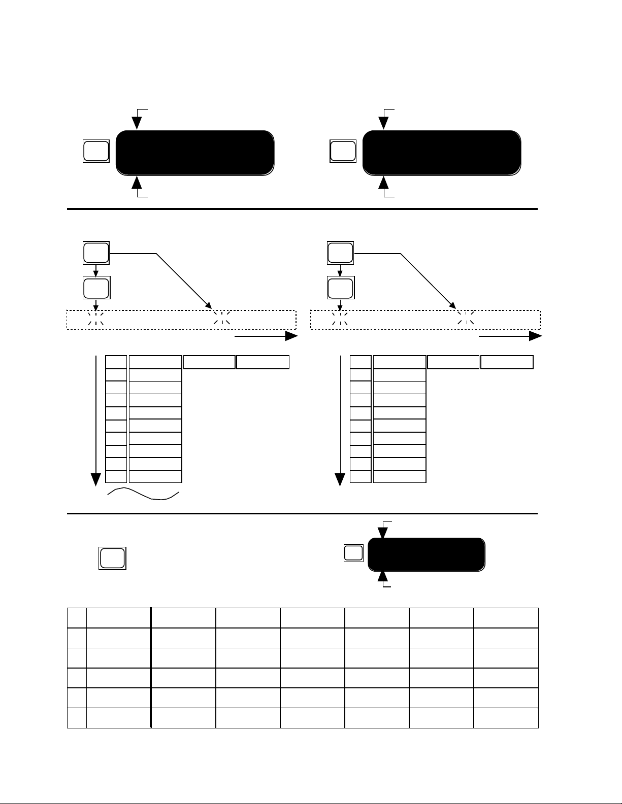
Machine Operation Mode
Machine Under LARC Control
VAR
MACHINE A
LARGE HALL
Program Currently Running
On power up, the 480L restores the configuration, routing, and programs loaded before
power was shut off. The LARC will display the last machine selected.
Program Currently Running
VAR
LARGE HALL
PAGE 1
Page of Parameters Under Control
Program Preview Mode Register Preview Mode
PROG
BANK
MA B1 P1
Preview Program
Banks
1
2
3
4
5
6
7
8
9
10
Halls
Rooms
Wild Spaces
Plates
Effects
Twin Delays
Sampling
Pitch/Doppler
Mastering
Compression
MA B1 P1 LARC Display
Preview Programs
Program 1
Large Hall
Press Numeric buttons 1-0 to
load Program. Press button
equal to flashing display to
load Program currently
displayed. Press the VAR
button, or move a slider, or
press a button under a slider
to return to MACHINE RUN
MODE
Program 2
Large + Stage
REG
BANK
MA B1 R1
Preview Register
Banks
1
2
3
4
5
6
7
8
9
10
REG Bank 1
REG Bank 2
REG Bank 3
REG Bank 4
REG Bank 5
CART Bank 1
CART Bank 2
CART Bank 3
CART Bank 4
CART Bank 5
MA B1 R1 LARC Display
Preview Registers
Register 1
REG 1
Press Numeric buttons 1-0 to
load Register. Press button
equal to flashing display to
load Register currently
displayed. Press the VAR
button, or move a slider, or
press a button under a slider
to return to MACHINE RUN
MODE
Register 2
REG 2
To Bank 21
Control Mode
Press
Page # Page Desc.
Configuration
Configuration
1
Copy Tools
Copy Tools
2
Name Preset
Name Preset
3
MIDI Patching
MIDI Patching
4
5
Configuration
6
2-4
to enter or exit CONTROL MODE
CTRL
MIDI
SysEx
Functions
Indicates You are in Control Mode
CONTROL MODE
VAR
PAGE 1
Page of Control Mode Parameters
Slider 1 Slider 2 Slider 3 Slider 4 Slider 5 Slider 6
Status
Copy
Configuration
From Source
To Destination
Sampling Rate
Clock
Power On
Default
Select Char.
Select Patch
SysEx Auto
SysEx Function
Srce. Controller
SysEc Channel
Source to
Transmit
Parameter Dest.
Pgm Change #
SysEx
Destination
Reg Table
Scale
Pgm Change
Mode
MIDI Channel
Input
REG Protect
Change Char.
Param. Value
Page 15
480L Owner's Manual
Basic Operation
Checking Your System's Status
Press CTRL to enter Control Mode. Press PAGE, then
press 1. Move slider one on page one of the control
program for a quick display of the following information:
• Configuration
• Sampling rate selected
• Clock source (internal or external)
• Input source (analog or digital)
• External Word Clock present/not present
• Register protection status
• Cartridge Status (formatted or unformatted,
present or not present)
480L Power-Up State
Normally if power is lost, or turned off, and then
restored, the 480L will return to its last previous state.
You can also configure the 480L to automatically load
pre-selected programs upon power up. To do this, go
to Control Mode, Page two, slider 5. This slider, labeled
DEF for default, is set at the factory to “off”. Advancing
the slider will scroll through all of the 480L programs
and select one as the new default state. The upper
display will indicate the machine you are addressing,
followed by the Bank number, Program number and
Program name. In order to select a default load for the
second machine, press the MACH button and advance
the slider to the desired program.
Control configuration is always remembered regardless of power-up default setting.
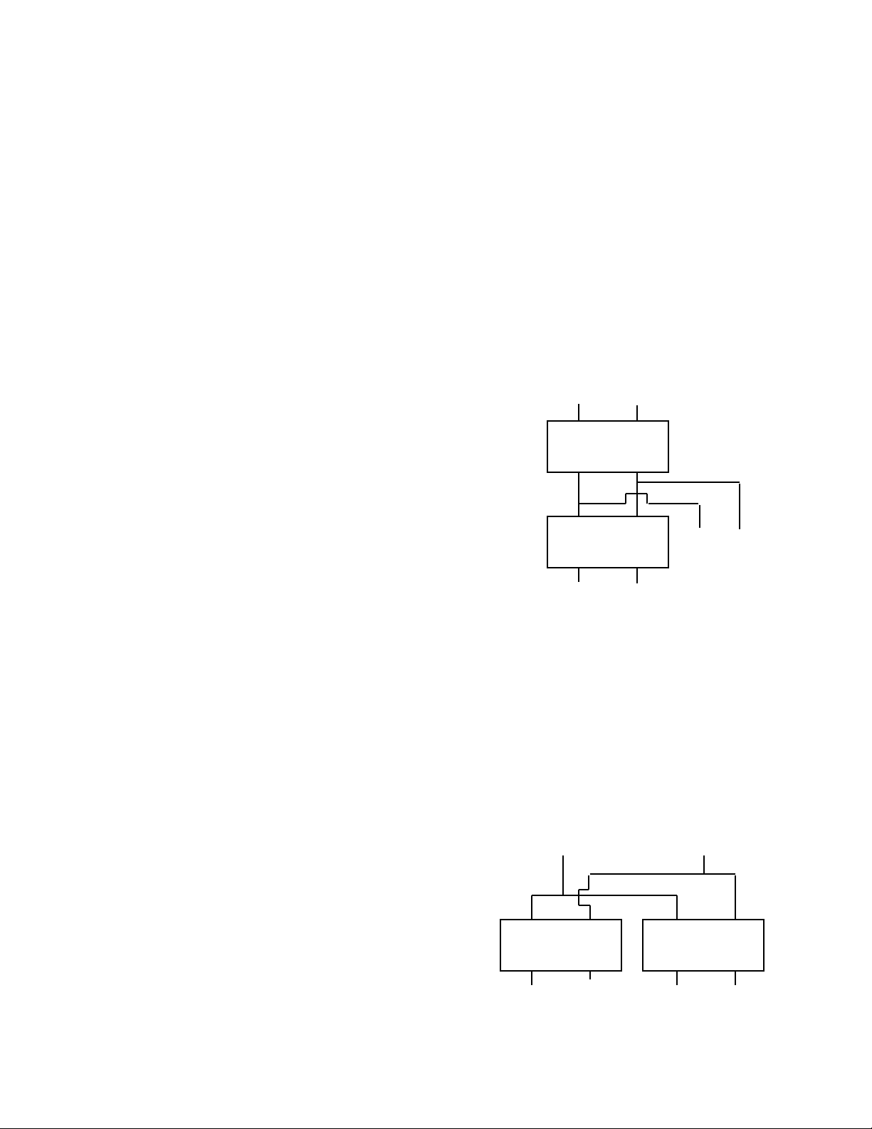
The Cascade Configuration
The Cascade configuration feeds the output of one
program (Machine A) directly into the input of the
second program (Machine B). This allows you to process a stereo signal with two entirely different effects-
-without ever leaving the digital domain. The Main
outputs are connected to Machine B, and contain the
processed signal from both Machine A and Machine B.
The Aux outputs contain only the signal from Machine
A.
In the Cascade configuration, the MIX control found in
most programs becomes very important, because it is
the only method you have of controlling the mix between the two programs.
Inputs
L R
Machine
A
Machine
B
L R
Main Outputs
L R
Aux Outputs
Selecting a Configuration
System configuration, input type and system clocking
are selected in Control Mode. To enter or exit Control
Mode, press CTRL.
Note: Pressing VAR will display the operating mode of
the mainframe.
Configurations are selected with Slider 2 on page 1 of
the control mode. There are four internal configurations available:
• Cascade
• Stereo Split
• Mono Split
• Single
Because the Configuration slider redefines the internal
architecture of the 480L, the display takes a bit longer
to update after you move the slider than other parameters. Let's take a closer look at the four configurations.
The Stereo Split Configuration
The Stereo Split configuration also uses the 480L as
two independent signal processors. It differs from the
Mono Split in that both inputs are sent to both programs; in other words, Machine A and Machine B
receive the same stereo input signal. The Main outputs
are used for Machine A, and the Aux outputs are used
for Machine B.
Inputs
L R
Machine
A
L R
Main Outputs Aux Outputs
Machine
B
L R
2-5
Page 16
Basic Operation
Lexicon
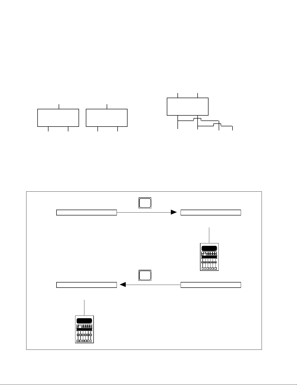
The Mono Split Configuration
The Mono Split configuration uses the 480L as two
independent signal processors. Each program has an
independent mono input and an independent stereo
output. The Left input always goes to the first program
(Machine A), and the Right input always goes to the
second program (Machine B). The Main Outputs produce stereo output from Machine A, and the Aux
Outputs produce stereo output from Machine B.
Inputs
L R
Machine
A
L R
Machine
B
L R
Main Outputs Aux Outputs
Selecting a Machine
Once a configuration has been selected, press CTRL
to exit Control Mode. Now, pressing MACH switches
LARC control from one machine to the other.
The Single Configuration
A few programs (like Stereo Sampler) require all of the
480L's processing power, and cannot be run at the
same time as other programs. The Single configuration
is provided for these programs. In the Single configuration, the outputs of the program are available at both
the Main and Aux Outputs.
Inputs
L R
Machine
A
L R
L R
Main Outputs Aux Outputs
MACHINE A
MACHINE A
HSP-1
HSP-1
Press
Press
MACH
HSP-2
MACHINE B
MACH
HSP-2
MACHINE B
2-6
Page 17
480L Owner's Manual
Basic Operation
Using Two LARCs
to Control a Single 480L
If you frequently use your 480L in the Split or
Cascade modes, you may wish to consider purchasing a second LARC. Having two LARCs allows
you to control two programs simultaneously, without
switching back and forth with MACH. Two LARCs
are also useful if the 480L is to be shared between
two different rooms.
In addition to controlling two programs at once, the
second LARC can be used to display two pages of
parameters for a single program.
The second LARC should be connected to the LARC
2 (Thru) connector on the rear panel of the 480L. Refer
to Chapter 1 for details.
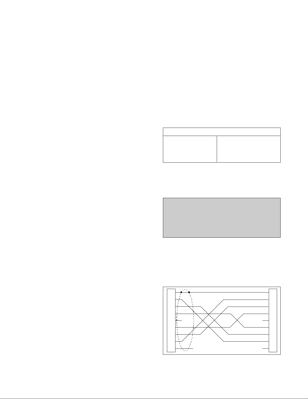
Controlling a 224XL
from a 480L and LARC
In facilities equipped with both a 480L and a 224XL, it
may be useful to control both systems from a single
LARC. To do this, connect the LARC 2 (Thru) connector to the 224XL LARC connector, as shown in
Chapter 1. Use the MACH key on the LARC to switch
the LARC between the 224XL and the 480L. If you are
running two programs on the 480L at the same time,
there will be three choices to step through each time
you press MACH.
Selecting Input Type
Slider 6 on Page 1 of Control Mode allows selection of
either analog or digital input. Both analog and digital
outputs are always active.
Before selecting digital input, be sure that proper
connections have been made to the 480L Digital I/O.
(See Chapter 1.)
Use the Clock slider on Page 1 of Control Mode to
select EXTERNAL CLOCK. Set digital clock and sampling rate to match your application according to the
table below.
Analog Digital
Clock Internal Clock External
Sampling Rate 44.1 or Sampling Rate to match Digital
48kHz Input Rate
Input Analog Input Digital
To determine whether the 480L is correctly receiving
external word clock, move the Status slider (Slider 1,
Page 1 of Control Mode) to display external word clock
status.
IMPORTANT
DO NOT POWER UP THE 480L WITH EXTERNAL
WORD CLOCK PRESENT AT THE 480L'S DIGITAL I/O PORT. DOING SO MAY PREVENT THE
UNIT FROM COMPLETING ITS NORMAL POWER
UP ROUTINE.
Connecting a 480L and a 224XL together simply allows
you to control the 224XL as you always have--none of
the 480L's new capabilities are added to it. For example, the 224XL cannot access the register mover or
other 480L control mode functions. Also, the 224XL
cannot be accessed by the LARC while the 480L is in
the control mode. If you press MACH while in the
control mode, the 224XL will not appear in the display.
As soon as you exit the control mode, the 224XL can
be selected.
1
2
3
4
5
6
7
8
9
SHIELD
NC NC
NC NC
224XL Mainframe Interconnect Cable Wiring
1
2
3
4
5
6
7
8
9
2-7
Page 18

Basic Operation
Lexicon
How to Load Programs
In order to complete system setup, you will have to load
programs into the 480L machines.
Remember that programs are variations of algorithms
with parameters that have been set at the factory.
Prorams are stored in Banks, with a collection of as
many as 10 similar programs stored in each bank.
Select a Bank
In order to select a program, you must first select the
bank in which the program is stored. There are two
ways to select banks:
1. Press PROG, then press BANK. This puts you in
Program Preview Mode. The bank number flashes to
indicate banks are being previewed, and the display
shows the current bank name and number.
Press BANK repeatedly. The LARC will scroll through
the banks and display their names.
2. Press PROG, then press BANK, then press one of
the numeric keys (two for double digit bank numbers)
to navigate directly to a specific bank.
Load a Program
480L programs are loaded by pressing the numeric
button that matches the flashing LARC display.
Press PROG, and then press a numeric button (1-0).
The LARC will flash the message "SETUP LOADED."
You will find that you can navigate between programs
very quickly with this method. For example, enter the
following keystrokes:
PROG BANK 1 PROG 1 = Large Hall
PROG BANK 9 PROG 7 = Stereo Parametric EQ
PROG BANK 7 PROG 4 = Dual Rate Chg Sampler
PROG BANK 8 PROG 8 = Indy Corner
PROG BANK 3 PROG 1 = Brick Wall
Once a program is loaded, the 480L will switch from
Program Preview Mode to Machine Operation Mode.
The new program name will be displayed, and the first
page of variable parameters will appear on the LARC.
Detailed information on program parameters is found
in later chapters of this manual.
Select a Program
Once a bank has been selected, you can view the
programs in that bank without loading them. To do this,
press PROG. The bank display on the LARC will stop
flashing and the program display will begin flashing.
The current program name and number will be displayed.
Press PROG repeatedly. The LARC will scroll through
the programs in the selected bank.
2-8
Page 19
480L Owner's Manual
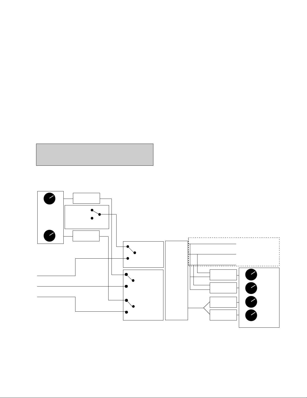
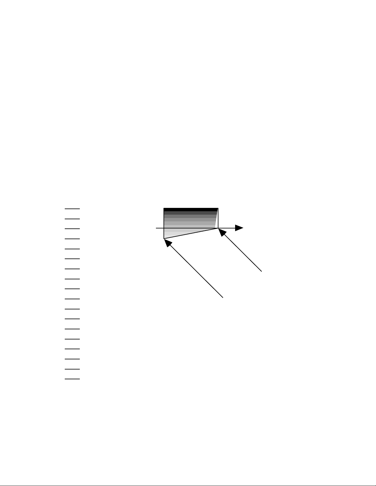
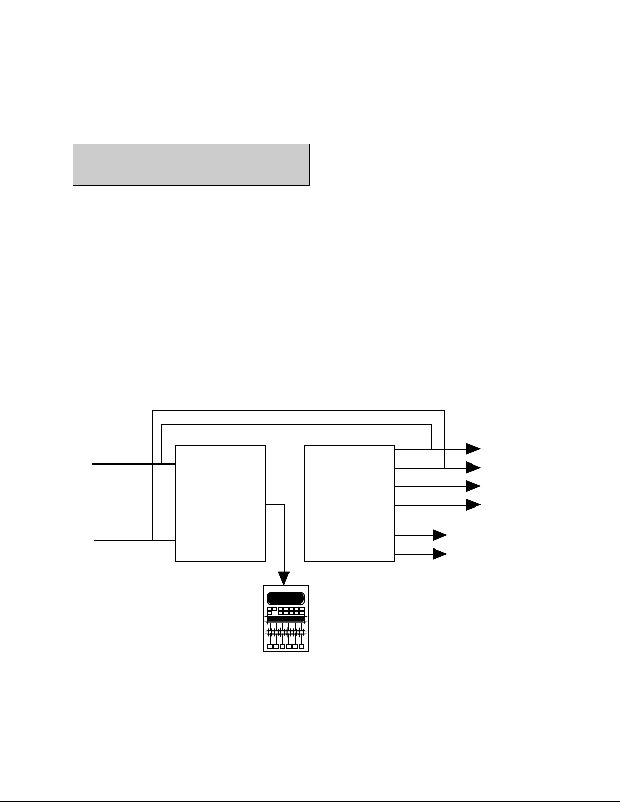
Level Calibration
Analog Input and Output levels should be set with care
to obtain the best possible performance from the 480L.
The diagram below illustrates the signal flow through
the mainframe. In addition, several programs are available in Bank 17 Test & Reference to help you optimize
the performance of your system.
Set Test Configuration
Use the Single Machine configuration:
1. Press CTRL, press PAGE, then press 1.
2. Move Slider 2 to select SINGLE.
3. Press CTRL or PROG to exit Control Mode and
enter Machine Operation Mode.
IMPORTANT
MUTE CONTROL ROOM MONITORS
BEFORE PROCEEDING.
Basic Operation
LEFT
Analog Input
Gain Stage
RIGHT
SDIF DIGITAL AUDIO
WORD CLOCK
LEFT CH. DATA
RIGHT CH. DATA
Left Channel
A/D Converter
44.1 kHz
48 kHz
Internal Sampling Frequncy
Right Channel
A/D Converter
INT.
EXT.
Word Clock Switch
LEFT CH. ANALOG
LEFT CH. DIGITAL
RIGHT CH. ANALOG
RIGHT CH. DIGITAL
Input Selector Switch
SIGNAL
PROCESSING
Wet
Bus
Data
WORD CLOCK
LEFT CH. DATA
RIGHT CH. DATA
Left MAIN
D/A Converter
Right MAIN
D/A Converter
Left AUX
D/A Converter
Right AUX
D/A Converter
SDIF DIGITAL
AUDIO INTERFACE
LEFT MAIN
RIGHT MAIN
LEFT AUX
RIGHT AUX
Analog Output Gain Stage
Signal Flow through the 480L Mainframe
2-9
Page 20
Basic Operation
Setting Analog Output Levels
Lexicon
The 480L has digital oscillator programs to aid in
setting system output levels.
Set nominal output level to design center of receiving
equipment as follows:
1. Load program 17.5 1kHz -12dB as follows:
Press PROG
Press BANK
Press 1, then press 7
Press PROG
Press 5
If additional headroom is desired, load program 17-4
(1kHz -17dB).
# Bits Dynamic Range
in dB
1
2
3
4
5
6
7
8
9
10
11
12
13
14
15
16
17
18
dBFS
-6 dB
-12 dB
-18 dB
-24 dB
-30 dB
-36 dB
-42 dB
-48 dB
-54 dB
-60 dB
-66 dB
-72 dB
-84 dB
-90 dB
-96 dB
-102 dB
-108 dB
LARC Meters 0VU or Design Center
+12 dB
+6 dB
HEADROOM
0 dB
-6 dB
-12 dB
-18 dB
-24 dB
-18 dB headroom for live recordings - Classical, Jazz
2. A digitally-generated 1kHz should appear at all
outputs (both analog and digital).
Set the analog output level controls for both Main and
Aux Out to register nominal operating level on the
device receiving this signal.
(Nominal Operating Level)
+8 dBv (1.95 volts)
+4 dBv (1.95 volts)
-10 dBv (0.245 volts)
-12 dB headroom for Pop recordings
Dynamic Range and Headroom Calibration
2-10
Page 21
480L Owner's Manual
Setting Analog Input Levels
Once output levels have been calibrated as directed in
the previous section, you can proceed to the input
levels.
Before proceeding, make sure that the Oscillator
program is loaded. Severe feedback can occur if
any other program is running.
1. Connect Main outputs L&R to the main inputs L&R
as shown below.
2. Press the button below the ILVL slider. The LARC
will display input level over a 90dB range from dBFS.
3. Adjust analog input gain controls until the LARC
LED display level reads 0dB.
4. Move the WAVE slider until 2 is displayed.
5. Press the button below ILEV to display input level.
6. Fine trim analog input gain controls until 78.0dB is
displayed for both left and right channels.
Basic Operation
Analog signals are calibrated for Unity Gain.
L
Signal
Audio
Signal
Processor
Input
R
Input Level Display
Signal
Processor
Outputs
Main Outputs
Aux Outputs
Digital Outputs
Signal Flow of Oscillator Program — Single Configuration
2-11
Page 22
Basic Operation
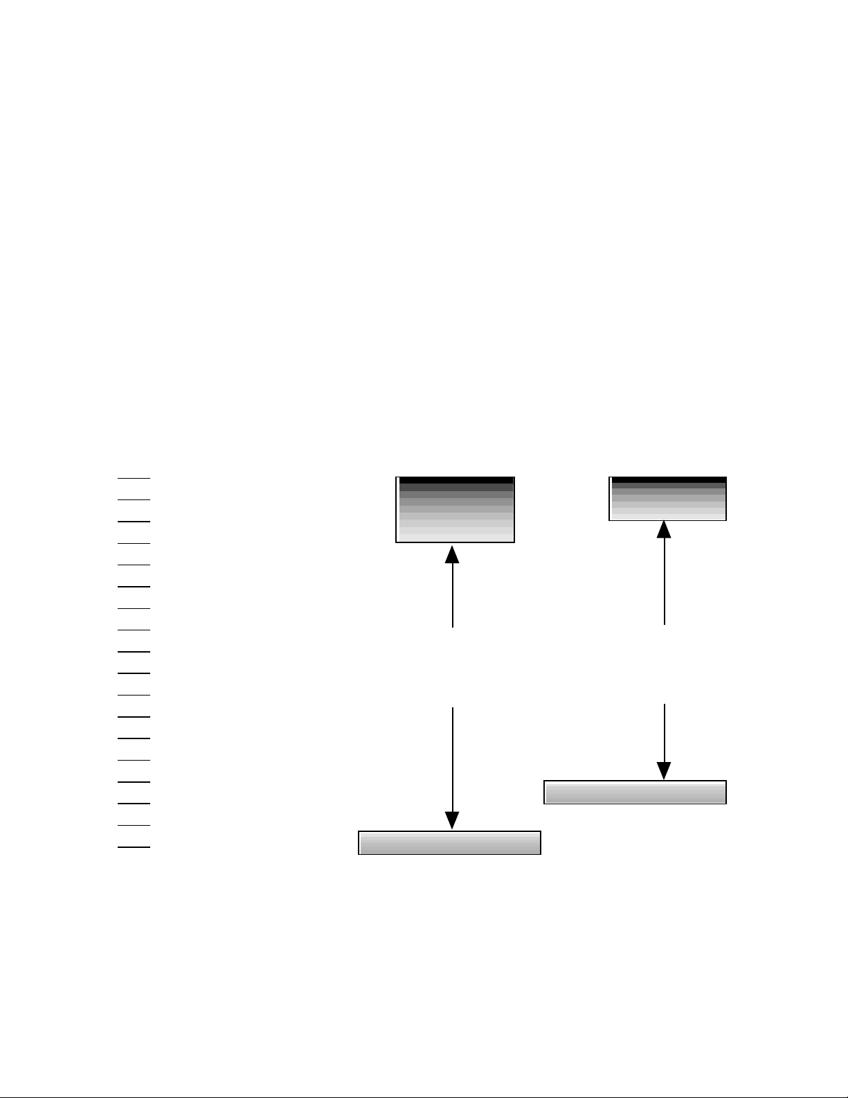
Levels in the Digital Domain
Analog signals, by nature, have an infinite range of
level. During conversion to digital, levels are quantized
to absolute values, and expressed as a number of bits.
The 480L provides 18-bit resolution in both the analog
and digital paths. In the digital domain, it is important to
provide adequate headroom so that peak amplitude
does not exceed dBFS. The difference between the
headroom provided and the dither noise, or least
significant bit, is the usable dynamic range of the
system.
As you can see in the figure below, the 480L provides
signal-to-noise and dynamic range that exceed many
popular digital recording media.
Lexicon
# Bits Dynamic Range
in dB
1
2
3
4
5
6
7
8
9
10
11
12
13
14
15
16
17
18
dBFS
-6 dB
-12 dB
-18 dB
-24 dB
-30 dB
-36 dB
-42 dB
-48 dB
-54 dB
-60 dB
-66 dB
-72 dB
-84 dB
-90 dB
-96 dB
-102 dB
-108 dB
LARC Meters Use of Dynamic Range
in an 18 bit system
+12 dB
+6 dB
0 dB
HEADROOM
-6 dB
-12 dB
-18 dB
-24 dB
84 dB Dynamic Range
18 dB Headroom
102 dB Theoretical Dynamic Range
18 Bit Dither Noise
Use of Dynamic Range
in a 16 bit system
HEADROOM
78 dB Dynamic Range
12 dB Headroom
90 dB Theoretical Dynamic Range
16 Bit Dither Noise
Dynamic Range of Digital Signal Path
2-12
Page 23
480L Owner's Manual
Using Digital Signals
Basic Operation
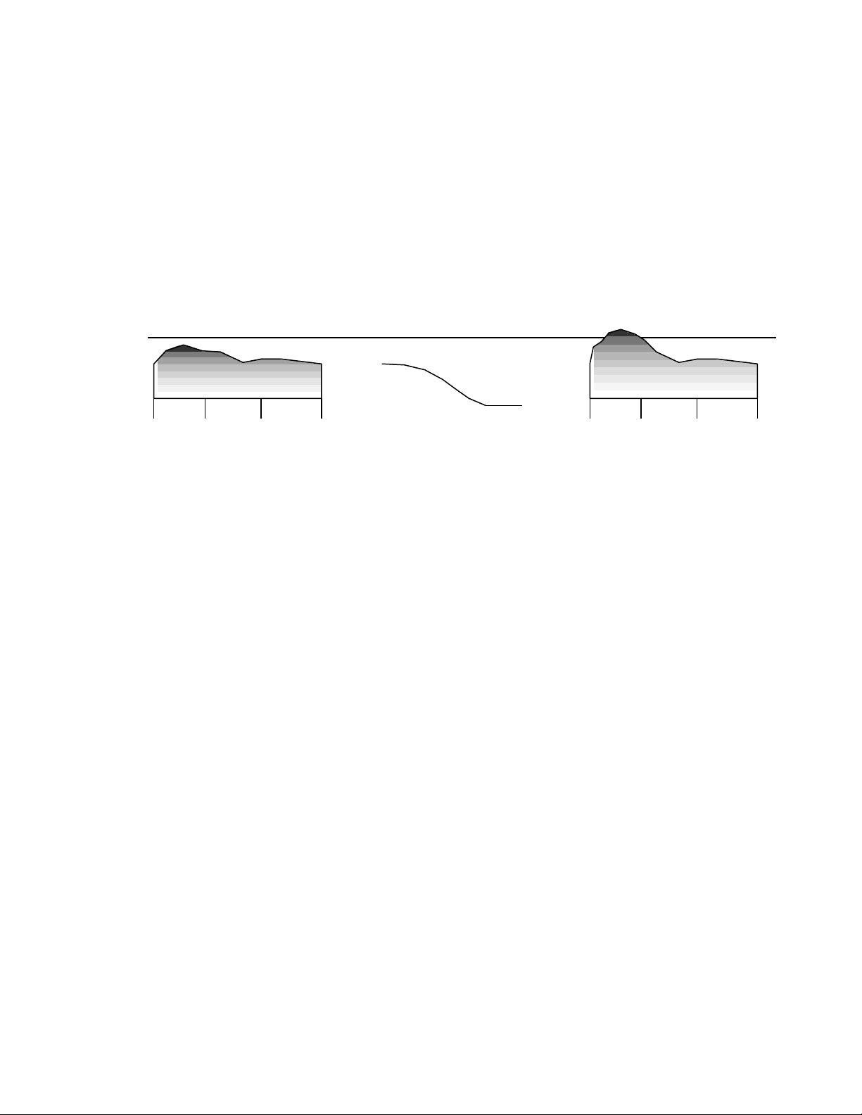
Several programs in the 480L allow you to increase the
level of the digital signal beyond dBFS. For example, if
the Parametric EQ program is loaded, and a low shelf
filter is boosted +6dB at 250Hz, the potential headroom
to dBFS is reduced accordingly. (See the figure below.)
If the audio material fed through this program contains
a large amount of energy in the region of the shelf
boost, an overload in the digital domain may occur.
When this happens, the last segments of the LARC
display will illuminate.
Many programs, such as Parametric EQ, have a master level control which can offset the overall gain to
prevent this situation. If you consistently encounter
such situations, contact Lexicon Customer Service.
dBFS
+ =
20 Hz 200 Hz 2 kHz 20 kHz 20 Hz 200 Hz 2 kHz 20 kHz
480L Parametric EQ
Low Shelf +6dB at 250 Hz
2-13
Page 24
Basic Operation
Lexicon
How to Edit Parameters
The sounds of the programs supplied with the 480L
cover an astounding range of possibilities, but sooner
or later you will want to alter the sounds of the programs
to more perfectly fit your requirements. Each program
in the 480L contains a set of parameters that can be
edited to create a sound uniquely your own.
After loading a program, you can edit its parameters by
moving the LARC's sliders. Most parameters can be
edited in real time to alter an effect. However, a few
parameters (like SIZE) have such a radical effect on
the 480L's algorithms that the effects signal is muted
briefly when they are edited.
To indicate the parameter that a slider controls, an
abbreviated code appears in the display window above
each active slider. You can display a more descriptive
title and the current value for each parameter by
pressing the keys directly below each slider. Moving a
slider also displays this information.
In many cases, pressing a display key twice will engage a vernier (fine) adjustment mode that allows very
precise adjustment. The display blinks to indicate that
the vernier mode is active.
How to Use Registers
The ability to edit parameters would be of little value if
there were no way for the 480L to store the edits. Not
to worry--the 480L has 100 registers available to store
edited versions of the programs. Registers are organized into banks, selected, and loaded exactly like the
programs. You can also edit parameters in a register,
and store the results in the same register or another
register.
There are five banks of ten registers in internal memory. Another five banks of ten registers can be stored
in a nonvolatile memory cartridge. One cartridge is
supplied with the unit, and additional cartridges may be
purchased.
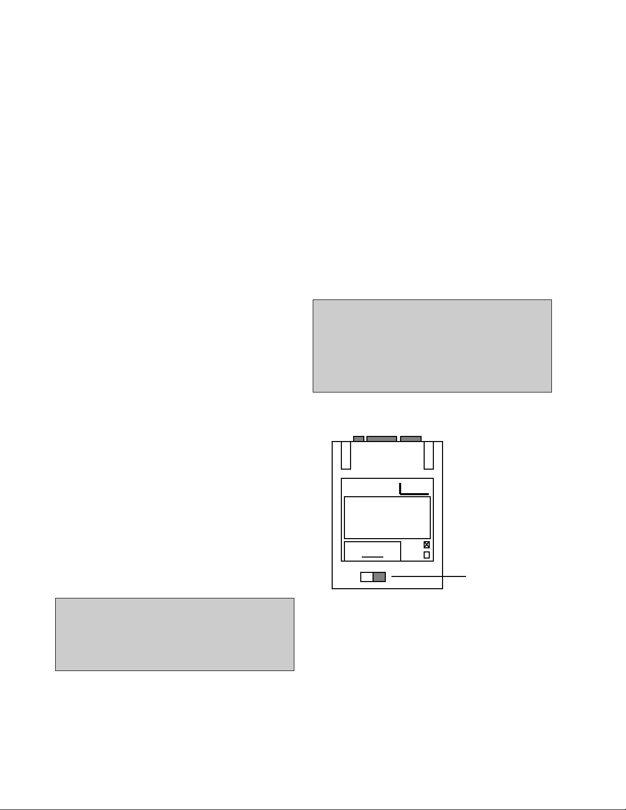
IMPORTANT
Cartridges are equipped with a write protect
switch. When the switch is ON, it prevents the
480L from writing to the cartridge, regardless
of the register protection selected in the 480L.
Cartridges may be shipped with the write protect switch in the ON position.
Change Pages to Access More
Parameters
Because the programs in the 480L have more than the
six parameters which the LARC can display at one
time, parameters are grouped in several pages. Each
page contains up to six parameters. You can use either
of two methods to move between pages:
1. Press PAGE repeatedly to step through the pages
sequentially.
2. Press PAGE and then a numeric-select key to go
directly to the page you want.
IMPORTANT
When a new program is loaded or another page
is selected, each slider is deactivated (i.e., the
display does not change) until the slider is
moved through its preset value.
When changes have been made on a page, and you
move to a new page, the previous edits remain intact.
However, when a new program is loaded, the edits you
made disappear forever (unless you stored the edits in
a register).
exicon
Write Protect
On Off
Write Protect
Switch
2-14
Page 25

480L Owner's Manual
Basic Operation
Storing and Naming Programs
After you have made the changes you want to a
program's parameters, you can store the changed
version in a register:
When you store a register, the edited program still has
the same name as the original program. To avoid
confusion, you can assign names to registers. To
rename a register:
1. Press CTRL to enter the control mode.
2. Press PAGE, then press 3 to go to page three.
3. Press the key under the slider marked SEL to
activate the select function. The current name of the
program appears in the lower display.
4. Move the SEL slider. Note that different characters within the name are selected by a pair of brackets
< > as you move the slider. Select the first character in
the program name.
5. Use the CHG slider to change the character. Note
that a blank space is available at the bottom of the
slider's range, as are several symbols.
6. Repeat steps 4 and 5 until all the characters in the
new name have been entered successfully.
Loading Registers
Registers are organized into banks, selected and
loaded in exactly the same manner as programs.
However, you press REG to switch from program to
register mode, and press REG instead of PROG when
selecting, storing, and loading registers.
Protecting Against
Loss of Register Contents
Setting up a large number of registers to meet your
personal requirements can represent a considerable
investment of time and effort. To reduce the possibility
of accidental loss of the contents of these registers, the
480L has a memory protection feature. When memory
protection is on, the 480L does not allow anyone to
erase the contents of a register by overwriting it.
However, unused registers can be written to.
The 480L has four protection levels:
• PROTECT INT AND CART
• PROTECT CART
• PROTECT INT
• PROTECT OFF
To store your newly-named program in a register:
1. Press REG once to exit Control mode, and enter
the register mode.
2. Press BANK repeatedly to locate the bank you
wish to store the register in. Banks 1 through 5 are
internal registers, and banks 6 through 10 are stored in
the nonvolatile memory cartridge.
Note: If you have difficulty using a cartridge, it
may not have been formatted. Also, cartridges
formatted with earlier versions of software
may not work with later versions until they are
reformatted. See Appendix B for instructions
on how to format the cartridge.
3. Press REG repeatedly to locate an "Unused"
register, or a register you don't mind erasing.
4. With the register number that you want to use
flashing on the display, hold down STO and press
REG. The LARC display flashes
SETUP STORED
This lets you know that the program was stored correctly.
PROTECT INT protects just the internal registers, but
allows registers stored in the cartridge to be overwritten. PROTECT CART protects the cartridge, but
allows internal registers to be overwritten. PROTECT
INT AND CART protects both internal and cartridge
registers. To activate memory protection:
1. Press CTRL to enter the control mode.
2. Press PAGE, 2 to go to page 2.
3. Move slider six to select one of the four protection
modes.
4. Press CTRL to exit the control mode.
Once activated, memory protection remains in effect
until it is turned off again.
2-15
Page 26

Basic Operation
Lexicon
Protecting Your Registers
Against Another Kind of Loss
After creating a collection of registers, some users may
not wish to let others access their "trademark" sounds.
If this concerns you, copy any internal registers that
you create to a nonvolatile memory cartridge at the end
of each session (using the register transporter in the
control mode). Then use the register clear function
(also found in the control mode) to remove the registers
from internal memory. Take the cartridge with you
when you leave the facility.
Use of the register transporter and register clear functions are described below.
Moving Registers Around
with the Register Transporter
The register transporter has four functions:
• Copy single registers from one location to
another
• Move single registers from one location to
another
• Copy all internal registers to a cartridge
• Copy all cartridge registers to internal memory
When registers are copied, the original register source
remains intact. When registers are moved, the original
register source is cleared.
To move or copy single registers:
1. Press CTRL to enter the control mode.
2. Press PAGE, 2 to go to page 2.
3. Use slider one to select MOVE or COPY.
4. Use slider two to select the source.
5. Use slider three to select the destination.
6. Hold down STO and press REG to complete the
copy or move.
Clearing Register Contents
Page two of the control mode has a CLEAR control that
allows complete removal of register contents. CLEAR
has three functions:
• Clear a single register
• Clear all internal registers
• Clear all cartridge registers
To clear a single register:
1. Press CTRL to enter the control mode.
2. Press PAGE, 2 to go to page two.
3. Use slider one to select CLR SETUP.
4. Use slider two to select the register that you wish
to clear.
5. Hold down STO and press REG to clear the
selected register.
IMPORTANT
The register protect function found on page
two of the control mode must be set to OFF if
any moves or copies are to overwrite existing
registers.
To copy entire register contents between internal and
cartridge memory:
1. Press CTRL to enter the control mode.
2. Press PAGE, 2 to go to page 2.
3. Use slider one to select CPY CART TO INTERNAL or CPY INTERNAL TO CART.
4. Hold down STO and press REG to complete the
copy.
Note: When either of these two modes are
selected, the SRC and DST sliders are inactive.
To clear all cartridge or internal registers:
1. Press CTRL to enter the control mode.
2. Press PAGE, 2 to go to page two.
3. Use slider two to select CLR ALL INT or CLR ALL
CART.
4. Hold down STO and press REG to clear the
selected registers.
Note: When either CLR ALL INT or CLR ALL
CART are selected, the BANK and REG sliders
are inactive.
2-16
Page 27

480L Owner's Manual
MIDI SysEx Program Dumps
Basic Operation
Programs and presets can also be transmitted and
received as MIDI SysEx data. Parameters that enable
MIDI SysEx dumps are found on Page 6 in Control
mode.
SysEx Bulk Dump
Slider 1 (SFN) selects a SysEx Bulk Dump function.
Slider 2 (SRC) is dependent on the SFN setting, but, in
general, it selects the source of the dump function
when required. The following SFN settings are available:
SETUP
BANK
ACTIVE
ALL INT
ALL CART
MIDI MAP
CONTROLS
Individual Program or Preset Dumps
The SETUP function will bulk dump a single program or
preset. When in this mode the SRCslider selects the
particular setup to dump. Moving the slider scrolls
through all of the available programs and registers
containing presets. After selecting a particular program
or preset, push and hold the STO button. While holding
STO, press REG. This will enable a dump of the
selected program or preset from either SFN or SRC
mode. The format of the setup bulk dump message is
described in Appendix A MIDI and the 480L.
Dumping Banks
The BANK function will bulk dump a whole bank of
programs or presets. The SRC slider selects from
among the program banks and all ten register banks
(five internal and five external cartridge banks).The
bank selected is then dumped by pushing STO and
REG as in individual setup dumps. A bank is dumped
as a contiguous group of ten programs or registers.
Each program or register within the bank, is dumped as
a separate SysEx message, using the same format as
that for individual dumps. When the dump is activated,
the LARC displays "DUMPING BANK." When the
dump is complete, the LARC displays "BANK
DUMPED."
Dump Active Algorithm(s)
The ACTIVE function dumps one or both of the active
algorithms and their current parameter values instead
of a register or preset. When the machine is in SINGLE
configuration, only Machine A can be dumped, otherwise Machine A, Machine B, or both A and B can be
selected with the SRC slider. As with all dumps described earlier, the dump is activated by the combination STO/REG button push. The format of the dump
message is described in Appendix A MIDI and the
480L.
If the SRC slider is set to “MACHINE A+B” each
machine will be sent as an individual SysEx message,
just as though you selected “MACHINE A” and did a
dump, then repeated the process for “MACHINE B”.
When the dump operation is activated, the LARC
displays "DUMPING ACT A" for Machine A only. The
LARC displays "DUMPING ACT B" for Machine B only,
or "DUMPING A+B" when both machines are selected.
When each Machine is dumped, the LARC displays
"ACT A(or B) DUMPED"
Dump All Internal Registers
To dump all internal registers to MIDI set SFN to “ALL
INT”. In this mode the SRC slider is not required.The
“ALL INT” dumps register banks from 1-5 to MIDI. Each
register is dumped as a single SysEx message described in Appendix A MIDI and the 480L..The presets
are dumped in order of appearance in the register
banks. As other functions, the dump action is initiated
by holding STO and pressing REG. Once the dump of
all internal registers is started, the LARC displays
"DUMPING INT." When the dump is completed, the
LARC displays "INT DUMPED."
Dump All Cartridge Registers
The dump all cartridge function is very similar to the
Dump All Internal Registers function with Banks 6-0
dumped rather than Banks 1-5. The LARC displays
"DUMPING CART." When the dump is completed the
LARC displays "CART DUMPED."
2-17
Page 28

Basic Operation
Lexicon
Dump MIDI Program Table Map
The 480L has a program map that translates MIDI
program change numbers to 480L program or register
numbers. There is a map for each Machine, A and B.
As in the ACTIVE function, the SRC slider selects from
three possibilities: Machine A, Machine B or Machine
A +B.The MIDI MAP bulk dump function dumps the
selected map(s) to the MIDI port. Dump action is
started holding STO and pressing REG. The format for
the MIDI map is documented in Appendix A MIDI and
the 480L. The LARC displays "DUMPING MAP A,"
"DUMPING MAP B," or "DUMPING MAPS," depending on selection. When the dump is complete, the
LARC displays "MAP (A, B or A+B) DUMPED."
Dump Controls
The SRC slider is not needed for this function. After
moving the slider to CONTROLS and pushing STO/
REG, a copy of the current parameters available in
Control Mode are dumped. The following is a list of the
controls dumped:
• Configuration
• Sample Rate
• Clock Source
• Input Source
• Audio Mute
• Reg Protect
• Sysex Channel Device ID
• Sysex Automation Mode
• Sysex Receive Mode
When dumping is activated, the LARC displays
"DUMPING CTRLS." When complete, the LARC displays "CTRLS DUMPED."
Slider 3, on Page 6, labeled RCV, selects the destination of MIDI bulk dumps loaded back into the 480L. The
simplest destination is the default, “ORIGINAL SRC”.
This function restores presets to wherever they originated. An internal register is written back over the
current register at that location. See the message
format documentation to discover the source for each
register. Programs or presets can also be restored to
the active Machines. If the configuration is SINGLE,
then only Machine A can be restored. Otherwise, any
program or register loaded to the 480L can be sent to
either Machine A or Machine B with “ACTIVE A” or
“ACTIVE B” selected under RCV.
The bank modes are more complicated. If any of the
“INT BNK” or “CART BNK” selections are made, any
preset will be sent to the first register in the selected
bank. The 480L will attempt to place subsequent
presets sequentially into the next registers in the bank
selected. This should only be used to restore dumped
banks.
Restore Individual Presets
Loading a previously dumped preset will replace the
preset at the location with the MIDI SysEx version
when the RCV slider is set to “ORIGINAL SRC”. Other
settings in the RCV slider cause other actions to occur:
“ACTIVE A” or “ACTIVE B” sends the preset to the
appropriate machine as a running program
Selecting one of the banks, loads the preset into the
first register of the bank, or into a subsequent register
if it was dumped in sequence with a previously restored
preset.
SysEx Restore Bulk Dump
2-18
Any attempt to restore a program to its original
source will be ignored. The error message "PROG
RCVD" will be displayed.
When presets are successfully restored, the LARC will
display an approrpiate message for each type:
"ACT A LOADED" or "ACT B LOADED" indicates that
an active algorithm was restored.
If a preset was received as an Internal Register, "1
REG LOADED" is displayed.
If a preset is received as a Cartridge register, "C REG
LOADED" is displayed.
Page 29

480L Owner's Manual
Basic Operation
Restore Banks
A dumped register bank will be restored to its original
location if “ORIGINAL SRC” is selected. If the bank was
a program bank, restoring to original source will not
change anything in the 480L.
If the RCV slider is set to an active Machine, all of the
programs or presets in the bank will load one at a time
into the selected Machine until the last one, which will
be left running when the process is complete.
When completed, the LARC will display "ACT A
LOADED," or ACT B LOADED," depending on the
Machine selected.
If a new bank is selected, it will be written to the new
location. The LARC will display either "1 REG
LOADED," or "C REG LOADED," depending on its
destination.
Restore Active Machines
Any dump of an active Machine will restore as that
active machine if the RCV slider is set to “ORIGINAL
SRC.” If the RCV slider is set to “MACHINE A” or
“MACHINE B,” the load will be to that machine, despite
any destination stored in the message itself.
When RCV is set to restore to a particular bank, then
the bulk dump data will replace the first register in the
bank unless the data for machine A and B are sent
sequentially, in which case the data will replace register 1 and 2 in the selected bank.
The LARC displays either "1 REG LOADED," or "C
REG LOADED," depending on its destination.
Restore All Internal Registers
If all of the dumped internal registers are restored with
the RCV slider set to “ORIGINAL SRC,” each register
will be overwritten. Any other setting of RCV is not
recommended.
Restore MIDI Program Table Map
Selection of destination is not an option when restoring
MIDI program table map. The data is restored to the
active Machine where it originated.
Restore Controls
Selection of destination is not an option when restoring
MIDI Controls. The data is restored to the control
parameters of the active Machine. See Dump Controls
for a list of the controls dumped and restored.
MIDI Request Data
The request data function is a MIDI SysEx message
that triggers an output of the requested bulk dump on
the MIDI port. The format for the request function is
defined in Appendix A MIDI and the 480L.. The possible requests are as follows:
• Request All Stored Presets(Internal and
Cartridge Registers)
• Request Individual Program
• Request Individual Preset
• Request Controls
• Request Active Machine A
• Request Active Machine B
• Request MIDI Program Map for Machine A
• Request MIDI Program Map for Machine B
The data will be sent after the 480L receives and
decodes the message. If automation transmit mode is
on, the data sent will also contain automation messages. Internally, the 480L decodes the request message and uses the normal event passing mechanism to
transmit the response. This activates the automation
mode if enabled. To get just the data requested, turn off
the automation transmit mode on the control page, or
by transmitting a SysEx message before sending the
request.
The LARC will display "1 REG LOADED."
Restore All Cartridge Registers
Restoring all cart registers works identically to the
restore all internal registers except that in “ORIGINAL
SRC” mode the data is sent to banks 6-0 instead of to
1-5. The LARC displays "C REG LOADED." All other
operations are the same.
2-19
Page 30

3
Banks 1-4: the Reverb Programs
In this chapter we'll discuss the original
Reverberation and Plate programs
created for the 480L.
Two different algorithms are used to create these
programs. The primary difference between the two is
the density of the reverberation. The algorithm with
greater density is used primarily for Room and Plate
programs. To discover which algorithm is used by a
particular program, go to page three to see how many
pre-echo voices are available — the dense algorithm
has only two voices.
Both algorithms have fixed, or "static" reverberation
characteristics. A new algorithm, with random motion
characteristics is described in Banks11 -12: Random
Halls and Rooms. The Random Hall algorithm provides a smoother reverberant characteristic, and is
better suited for material which requires large space
emulation, or longer reverb time.
Page 31

Banks 1-4: the Reverb Programs
Before we jump into detailed descriptions of the
programs and parameters, let's take a look at the
philosophy behind the reverberation algorithm's radical new structure.
About the
Reverberation Algorithm
The 480L incorporates the results of a great deal of
research into acoustics and reverberation. It produces
four general classes of sounds: ambience, room simulations, plates, and gated sounds.
In Search of Ambience
Ambience is the use of reverberation or reflected
sound energy to give recorded music a sense of being
performed in a real acoustic location. Ideally, ambience gives warmth, spaciousness and depth to a
performance without coloring the direct sound at all.
Recent research into ambience has shown that this
phenomenon depends most critically on the shape of
the initial reverberation build-up and decay. Ambience
is perceived and has benefit while the music is running
(which is most of the time). But once the reverberation
has decayed 15 dB it is no longer audible in the
presence of the direct sound. So the time it takes for the
sound to build up and decay 15 dB determines the
perceived reverb time, regardless of what the decay
time to -60 dB is. Some very good halls for recording
have a rather uneven initial build-up and decay, giving
a much longer effective reverb time than their -60 dB
reverb time might suggest.
It has become common practice to use predelay in an
attempt to emulate the sound of these halls. Adding
delay to the reverb sends definitely increases the
effective audible reverb time and the apparent size of
the hall, but the result sounds unnatural.
If we make echograms of real halls, we find that there
is usually a gradual buildup of energy between the
arrival of the direct sound and the time at which the
reverberation reaches maximum loudness. The sharp
attack of added predelay in most reverberation devices
sounds entirely different.
In the 480L, the SIZE, SPREAD and SHAPE controls
allow adjustment of the buildup and decay of the initial
part of the reverberation envelope. SHAPE controls
the shape of the envelope, while SPREAD and SIZE
set the time over which this shape is active.
Lexicon
In the hall and room programs, SIZE acts as a master
control for the apparent size of the space being created
by the 480L. Both SPREAD and RT MID varylinearly
with the setting of SIZE. Thus maximum reverb time
and spread require high settings of SIZE. To find an
appropriate reverb sound, start with a preset with a
similar sound to what you want to end up with. Simply
varying SIZE is often sufficient to arrive at the exact
sound you are seeking.
Once a size has been selected, SPREAD and SHAPE
are used to adjust the shape and duration of the initial
reverb envelope, which together provide the major
sonic impression of room size.
When SHAPE is at minimum, the reverberation envelope builds up very quickly to a maximum amplitude,
and then dies away quickly at a smooth rate. This
envelope is characteristic of small reverberation chambers and reverberation plates. There are few (if any)
size cues in this envelope, so it is ineffective in creating
ambience. With this SHAPE setting, SPREAD has no
effect. The density is set by the size control, and the
rate of decay is set by RTMID. This reverberation
envelope is typical of many of the popular digital
reverberators of the last few years.
As SHAPE is raised to 32 (about 1/8th of the way up)
the initial sharp attack of the reverberation is reduced,
and reverberation builds more slowly. The envelope
then sustains briefly before it begins to die away at the
rate set by RTMID. SPREAD has little or no effect on
this shape.
When SHAPE is at 64 (1/4 of the way up) buildup is
even slower and the sustain is longer. Now SPREAD
affects the length of both the buildup and the sustain.
As a rough estimate, the sustain will be approximately
the time value indicated by the SPREAD display (in
milliseconds).
As SHAPE is raised further, the buildup and sustain
remain similar, but now a secondary sustain appears in
the envelope, at a lower level than the first. This
secondary plateau simulates a very diffused reflection
off the back wall of a hall, and is effective in creating a
sense of size and space. This reflection becomes
stronger and stronger, reaching an optimal loudness at
a SHAPE value of about 128 (1/2 way up).
The highest SHAPE settings are typically used for
effects. Near the top of the scale the back wall reflection
becomes stronger than the earlier part of the envelope,
resulting in a inverse sound.
3-2
Page 32

480L Owner's Manual
Banks 1-4: the Reverb Programs
Note that none of these shape effects are audible
unless RTMID is set short enough. Generally, RTMID
should be set to a value of about 1.2 seconds for small
rooms, and up to 2.4 seconds or so for halls. SIZE
should also be set to a value appropriate to the desired
hall size (note, however, that small sizes color the
reverberation).15 meters makes a very small room,
and 38 meters is useful for a large hall.
Used with care SHAPE and SPREAD allow the 480L to
produce superior ambience—a sound which is spacious and has great depth—without the long RT60 of a
church.
Creating a Realistic Ambient Sound
When you set out to create an ambient sound, the first
and most important decision is how big a space you
want. The best way to start is to listen to several presets
and choose the one which sounds closest to what you
have in mind. If necessary, use SIZE to make a slightly
larger or smaller sound, as needed.
Next use RTMID to fine-tune the amount of time the
reverberation takes to die away at the end of musical
phrases. Actual halls vary a great deal in their actual RT
MID values. The setting of the BASS MULTIPLY is also
critical in matching the sound of an existing hall. An
ideal concert hall would have a BASS MULTIPLY
setting of 1.2. It is rare when actual physical spaces
exceed 1.5. Many (if not most) good recording environments have values of BASS MULTIPLY of 1.0 or less,
and a value of 0.8 should be tried when attempting to
match an existing hall.
There are two additional controls to deal with. SHAPE
and SPREAD adjust the effective reverb time when the
music is running. Higher values of SHAPE and
SPREAD produce a longer effective reverb time.
Longer effective reverb times give greater spaciousness to the sound.
The Early Reflection Myth
The importance of early reflections in reverberation
has become accepted as indisputable fact. We call it a
myth. Much of the myth of early reflections is a result of
attempts to emulate the sound of discrete reflections
from the floor, stage area, and ceiling of a real hall. This
sounds reasonable in theory, but it has been our
experience that the resulting preechoes are much
different from the early reflections present in real halls,
and recorded music is often better off without them.
The reason for the difference is not difficult to discover.
Early reflections in artificial reverberation are usually
discrete--simply a delayed version of the original
sound. Transients such as clicks or drums are clearly
heard as discrete reflections, resulting in a coarse,
grainy sound. But the reflective surfaces of real halls
are complicated in shape, and the reflections they
produce are smoothed or diffused. Their time and
frequency responses are altered, making them much
more interesting. In a very good hall, discrete reflections are hard to identify as such.
Another major disadvantage of discrete early reflections is that the same reflection pattern is applied to
every instrument which is fed into the reverberation
unit, and each instrument has its timbre altered in
exactly the same way. In a real hall, every instrument
has a different set of early reflections, and each instrument will have its timbre altered in a different way.
Some engineers find any type of early reflection undesireable. In classical music, many recordings are now
made with the orchestra in the middle of the hall, with
the specific intention of avoiding early reflections. Too
much early reflected energy makes the sound muddy,
and does not add to richness or spaciousness. This is
in part because reflections and reverberation also exist
in the playback room.
The 480L reverberation algorithm still offers the option
of adding early reflections (preechoes) but we have
made them diffused clusters of preechoes. The density
of the cluster is set by the DIFFUSION control. We
recommend that these preechoes be used with caution, unless you are trying to match the sound of the
reverberation to a particular location where such reflections are strong.
When creating new reverberation sounds of your own,
don't forget that an Effects program can be put in series
with the reverberation (using the Cascade configuration described in Chapter 2). The result can be
extremely interesting. Also, try using the Effects program to give high frequencies a different envelope from
low frequencies.
3-3
Page 33

Banks 1-4: the Reverb Programs
RTM
Mid Reverb Time
SHP
Shape
SPR
Spread
DIF
Diffusion
BAS
Bass Multiply
DCO
Decay Optimization
HFC
High Freq Cutoff
PDL
Predelay
RTC
RT Hi Freq. Cutoff
MIX
Wet/Dry Mix
[
Echo Level 1 L>L
PRE-
Echo Level 2 R>R
ECHO
Echo Level 3 R>L
-LEV
Echo Level 4 L>R
ELS-
Echo Level 5 L>L
]
Echo Level 6 R>R
[
Echo Delay 1
PRE-
Echo Delay 2
ECHO
Echo Delay 3
-DEL
Echo Delay 4
AY5
Echo Delay 5
]
Echo Delay 6
SIZ
Size
XOV
Crossover
Page One
Page Two
Page Three
Page Four
About the Reverberation Parameters
Page One
Lexicon
RTM (Mid-Frequency Reverb Time)
RTM sets the reverb time for mid-frequency signals
when the signal stops. Because low-frequency reverb
time (BASS MULT) is a multiplier of RTM, RTM acts as
a master control for the stopped reverb time. When
DECAY OPT is set to Reverb mode, the actual value
set for RTM varies with the setting of SIZE. SIZE should
be adjusted before RTM. This interaction is deactivated when DECAY OPT is set to EFFECTS mode.
SHAPE
SHAPE and SPREAD work together to control the
overall ambience of the reverberation created by the
480L. SHAPE determines the contour of the reverberation envelope. With SHAPE all the way down,
reverberation builds explosively, and decays quickly.
Note: SPREAD only functions when
SHAPE is set higher than eight.
As SHAPE is advanced, reverberation builds up more
slowly and sustains for the time set by SPREAD. With
SHAPE in the middle, the buildup and sustain of the
reverberation envelope emulates a large concert hall
(assuming that SPREAD is at least halfway up, and
that SIZE is suitably large—30 meters or larger.)
SPREAD
SPREAD works together with SHAPE to control the
contour of the overall ambience of the sound created
by the 480L. SPREAD controls the duration of the initial
contour of the reverberation envelope (SHAPE controls the envelope). Low SPREAD settings result in a
rapid onset of reverberation at the beginning of the
envelope, with little or no sustain. Higher settings
spread out both the buildup and sustain.
SPREAD and SHAPE control the rate at which reverberation builds up, and how the reverberation sustains
as it begins to decay. When DECAY OPT is in Reverb
mode, SPREAD is linked to SIZE, and the actual value
for SPREAD depends on the selected SIZE.
SIZE
SIZE sets the rate of buildup of diffusion after the initial
period (which is controlled by DIFFUSION). It also acts
as a master control for RT MID and SPREAD. For this
reason, the SIZE control can be used to vary a reverb
sound from very large to very small. Generally, you
should set the SIZE control to approximate the size of
the acoustic space you are trying to create. The size in
meters is roughly equal to the longest dimension of the
space. Moving SIZE while a signal is present momentarily mutes the reverb signal.
3-4
Page 34

480L Owner's Manual
0 dB
-30 dB
Time
0 dB
-30 dB
Time
Time
0 dB
-30 dB
Time
0 dB
-30 dB
Banks 1-4: the Reverb Programs
The apparent size of the space created is actually a
combination of the settings of the SIZE, SHAPE, and
SPREAD controls. Small acoustic spaces are characterized by a rapid buildup of diffusion. However, both
small and large spaces frequently have an uneven
buildup of initial reverberation. This uneven buildup is
what is controlled by the SPREAD and SHAPE controls.
SHAPE Set All the Way Down.
SHAPE at 64 - 1/4 of the Way Up.
HF CUTOFF
HF CUTOFF sets the frequency above which a 6 dB/
octave low-pass filter attenuates the processed signal.
It attenuates both preechoes and reverberant sound.
High frequencies are often rolled off with this parameter, resulting in more natural sounding reverberation.
PREDELAY
PREDELAY sets the amount of time which elapses
between input of signal and the onset of reverberation.
Under natural conditions, the amount of predelay depends on the size and construction of the acoustic
space and the relative position of the sound source and
the listener(s). PREDELAY attempts to duplicate this
phenomenon and is used to create a sense of distance
and volume within an acoustic space. Relatively long
PREDELAY settings place the reverberant field behind
rather than on top of the input material. Extremely long
PREDELAY settings produce unnatural sounds that
often prove interesting.
A sense of continuity between source and reverb is
maintained up to around 40 ms of predelay, after which
the sound begins to separate into distinct patterns;
however, large values of PREDELAY can effectively
give the impression of large size if early reflections are
used to fill in the spaces between input and the delayed
reverberation.
SHAPE at 128 - 1/2 of the Way Up.
SHAPE at 255 - All the Way Up.
Short RT MID Setting.
Much of the effect of PREDELAY can be better
achieved by using medium values of SHAPE, and
setting the desired apparent predelay with SPREAD.
Setting these parameters should be done by ear, since
the values don't relate directly to ms.
Note: Very high values of PREDELAY limit the
amount of SPREAD available. The display does not
reflect this, however.
3-5
Page 35

Banks 1-4: the Reverb Programs
Page Two
Lexicon
BASS MULTIPLY
BASS MULTIPLY sets the reverb time for low-frequency signals, as a multiplier of the RT MID parameter. For example, if BASS MULTIPLY is set to 2X, and
RT MID is set to two seconds, the low frequency reverb
time will be four seconds. For a natural-sounding hall
ambience, we recommend values of 1.5X or less.
CROSSOVER
CROSSOVER sets the frequency at which the transition from LF RT to RT MID takes place. CROSSOVER
should be set at least two octaves higher than the low
frequency you want to boost. For example, to boost a
signal at 100 Hz, set the CROSSOVER to 400 Hz (This
setting works well for classical music). CROSSOVER
works best around 500 for boosting low frequencies,
and around 1.5 kHz for cutting low frequencies.
RT HF CUT
RT HF CUT sets the frequency above which sounds
decay at a progressively faster rate. It filters all the
sound except the preechoes. When set relatively low,
it gives a darker tone to the reverberation, simulating
the effect of air absorption in a real hall. This also helps
keep the ambience generated by the program from
muddying the direct sound.
DIFFUSION
DIFFUSION controls the degree to which initial echo
density increases over time. High settings of DIFFUSION result in high initial buildup of echo density, and
low settings cause low initial buildup. After the initial
period (in which echo buildup is controlled by DIFFUSION) density continues to change at a rate determined by SIZE. To enhance percussion, use high
settings of diffusion. For clearer and more natural
vocals, mixes, and piano music, use low or moderate
settings of diffusion. The plate presets and some of the
room presets use an algorithm with higher inherent
diffusion. If high diffusion is desired, start with one of
these presets. They are easily identifiable because
they have only two preechoes.
DECAY OPT (Decay Optimization)
DECAY OPT alters program characteristics in response to changes in input level, to make reverberation
decay sound more natural. DECAY OPT should normally be set to REVERB 7.
To make it easy to create "wild spaces" DECAY OPT
has a second mode--EFFECTS. In the EFFECTS
mode, the numbers 0 - 9 have the same effect as they
do in the REVERB mode. However, in the EFFECTS
mode the SPREAD control is not linked to the SIZE
control, making it possible to use high values of
SPREAD with low values of SIZE. These settings can
result in some interesting, but unnatural sounds.
Note: On certain types of program material (such as
soft low-frequency tones from a synthesizer) side
effects may be audible during level changes. If these
are heard, set DECAY OPT to REVERB 0 or EFFECTS 0.
WET/DRY MIX
WET/DRY MIX controls the ratio of direct vs. effect
signal in the output from a program. When the 480L is
patched into a console, this control should almost
always be set to 100% wet. When an instrument is
plugged directly into a 480L, or when the Cascade
configuration is in use, a setting between 45 and 60%
is a good starting point for experimentation with this
parameter.
WET/DRY MIX is a sine/cosine fade. Practically
speaking, this means that MIX can be adjusted over its
range with little or no change in output level. When you
control mix at the console, adding effect to the dry
signal increases overall level.
3-6
Page 36

480L Owner's Manual
Page Three
PREECHO LEVEL
Preechoes can best be understood by visualizing a
stage where the early reflections are the sounds emanating from the rear and side stage walls directly after
the sound from the stage. Usually the rear stage wall
reflection is earlier and louder than those from the two
side walls. The preechoes are actually clusters of
echoes, with the density of the cluster set by DIFFUSION.
The preecho reflection parameters change the perceived locations of reflecting surfaces surrounding the
source. PREECHO LEVEL adjusts the loudness of the
reflection.
Note: Some of the presets use an algorithm with
six preechoes, and others only have two. If you
need more than two when creating a sound, be
sure to start with a preset that has six.
Page Four
Banks 1-4: the Reverb Programs
PREECHO DELAY TIME
For each of the PREECHO LEVEL parameters, there
is a corresponding PREECHO DELAY TIME parameter. PREECHO DELAY TIME sets the delay time in ms
for one of the preechoes. PREECHO DELAY TIME is
not affected by PREDELAY, so preechoes can be
placed to occur before the reverberation starts.
3-7
Page 37

Banks 1-4: the Reverb Programs
Programs — Bank 1: Halls
Lexicon
1 Large Hall
RTM SHP SPR SIZ HFC PDL
2.19 s 126 179 37 m 2.862 24 ms
BAS XOV RTC DIF DCO MIX
1.2 x 752 Hz 4.186 99 R 7 All Fx
Preecho Levels
Off Off Off Off Off Off
Preecho Delays
0 ms 0 ms 0 ms 0 ms 0 ms 0 ms
2 Large+Stage
RTM SHP SPR SIZ HFC PDL
2.19 s 126 179 37 m 2.862 24 ms
BAS XOV RTC DIF DCO MIX
1.2 x 752 Hz 4.186 99 R 7 All Fx
Preecho Levels
-12 dB -10 dB -8 dB -8 dB -9 dB -9 dB
Preecho Delays
16 ms 22 ms 64 ms 56 ms 112 ms 102ms
3 Medium Hall
RTM SHP SPR SIZ HFC PDL
1.74 s 126 128 25 m 4.395 24 ms
BAS XOV RTC DIF DCO MIX
1.2 x 752 Hz 3.982 99 R 7 All Fx
Preecho Levels
Off Off Off Off Off Off
Preecho Delays
0 ms 0 ms 0 ms 0 ms 0 ms 0 ms
6 Small+Stage
RTM SHP SPR SIZ HFC PDL
1.13 s 96 50 25 m 4.395 24 ms
BAS XOV RTC DIF DCO MIX
1.0 x 752 Hz 3.784 99 R 7 All Fx
Preecho Levels
-12 dB -12 dB -10 dB -10 dB -14 dB -14 dB
Preecho Delays
12 ms 18 ms 44 ms 36 ms 72 ms 52ms
7 Large Church
RTM SHP SPR SIZ HFC PDL
4.04 s 85 247 38 m 2.523 30 ms
BAS XOV RTC DIF DCO MIX
1.5 x 1.02 Hz 2.691 80 R 7 All Fx
Preecho Levels
Off Off Off Off Off Off
Preecho Delays
0 ms 0 ms 0 ms 0 ms 0 ms 0 ms
8 Small Church
RTM SHP SPR SIZ HFC PDL
2.42 s 65 106 31 m 3.402 0 ms
BAS XOV RTC DIF DCO MIX
1.0 x 752 Hz 3.591 70 R 7 All Fx
Preecho Levels
Off Off Off Off Off Off
Preecho Delays
0 ms 0 ms 0 ms 0 ms 0 ms 0 ms
4 Medium+Stage
RTM SHP SPR SIZ HFC PDL
1.74 s 126 128 25 m 4.395 24 ms
BAS XOV RTC DIF DCO MIX
1.2 x 752 Hz 3.982 99 R 7 All Fx
Preecho Levels
-14 dB -12 dB -10 dB -10 dB -12 dB -12 dB
Preecho Delays
16 ms 22 ms 44 ms 38 ms 80 ms 76ms
5 Small Hall
RTM SHP SPR SIZ HFC PDL
1.13 s 96 50 25 m 4.395 24 ms
BAS XOV RTC DIF DCO MIX
1.0 x 752 Hz 3.784 99 R 7 All Fx
Preecho Levels
Off Off Off Off Off Off
Preecho Delays
0 ms 0 ms 0 ms 0 ms 0 ms 0 ms
3-8
9 Jazz Hall
RTM SHP SPR SIZ HFC PDL
1.26 s 34 98 23 m 12.177 0 ms
BAS XOV RTC DIF DCO MIX
1.2 x 752 Hz 5.538 80 R 7 All Fx
Preecho Levels
Off Off Off Off Off Off
Preecho Delays
0 ms 0 ms 0 ms 0 ms 0 ms 0 ms
0 Auto Park
RTM SHP SPR SIZ HFC PDL
5.29 s 149 247 38 m 7.818 24 ms
BAS XOV RTC DIF DCO MIX
1.0 x 752 Hz 5.538 99 R 0 All Fx
Preecho Levels
-6 dB -6 dB -9 dB -9 dB -12 dB -12 dB
Preecho Delays
22 ms 12 ms 44 ms 66 ms 164 ms 136ms
Page 38

480L Owner's Manual
Banks 1-4: the Reverb Programs
Program Descriptions
The programs in the Halls bank are reverberation
programs designed to emulate real concert halls.
While the Halls are useful for a wide variety of tasks,
they are especially good with traditional and classical
music. For popular music, they can be used to give
multitrack recordings the sense of belonging to the
same performance, by putting the whole mix in the
context of a real-sounding acoustic space.
1 Large Hall
Large Hall provides the sense of space and ambience
of a large concert hall to music which has already been
mixed.
Acoustically, the sound of this program resembles a
large, relatively square concert hall. The musicians are
not placed in a stage area at one end, but in the middle
of the hall, away from nearby walls and other surfaces
that produce reflections. The reverberant pickups are
located between the sound source and the walls, and
are directed away from the musicians, so they pick up
little or no direct energy.
2 Large + Stage
Large + Stage is similar to Large Hall, except that the
musicians are located at one end of the hall, and
several preechoes simulate the effects of a procenium
arch.
3 Medium Hall
Medium Hall is very similar to Large Hall, but smaller.
4 Medium + Stage
Medium + Stage is very similar to Large + Stage, but
smaller.
5 Small Hall
Small Hall is a smaller version of Medium Hall.
6 Small + Stage
Small +Stage is a smaller version of Medium + Stage.
7 Large Church
Large Church is a big space with the musicians centrally located, and a comparatively long RT MID.
8 Small Church
Small Church is a smaller version of program 7.
The resulting reverberation has the space and ambience of a large hall, but does not color or muddy the
direct sound of the recording. Because of the large
SPREAD value used, the sound of the Large Hall is
most effective when relatively small amounts of it are
mixed with the direct signal. If the reverberation sounds
obtrusive or tends to reduce clarity, you are using too
much of it!
BASS MULT, RT HF CUT, and HF CUTOFF have been
set to values typical of good concert halls. SIZE is set
at maximum to provide reverberation with medium
density and low color. If higher density is required (for
material such as closely-miked percussion) try reducing SIZE to about 25.
9 Jazz Hall
Jazz Hall is a relatively small space with hard bright
walls and a short RT MID. It emulates a hall full of
people, without the noise they make. It has high diffusion, and sounds good with jazz or pop material.
0 Auto Park
Auto Park reproduces the sound of an underground
parking garage.
3-9
Page 39

Banks 1-4: the Reverb Programs
Programs — Bank 2: Rooms
Lexicon
1 Music Club
RTM SHP SPR SIZ HFC PDL
1.03 s 40 55 25 m 7.181 0 ms
BAS XOV RTC DIF DCO MIX
1.0 x 752 Hz 3.784 78 R 7 All Fx
PDE PDE
Off Off
PDL PDL
0 ms 0 ms
2 Large Room
RTM SHP SPR SIZ HFC PDL
0.70 s 52 82 19 m 6.593 0 ms
BAS XOV RTC DIF DCO MIX
1.0x 752 Hz 3.784 65 R 7 All Fx
PDE PDE
Off Off
PDL PDL
0 ms 0 ms
3 Medium Room
RTM SHP SPR SIZ HFC PDL
0.50 s 22 10 19 m 7.181 0 ms
BAS XOV RTC DIF DCO MIX
1.0 x 752 Hz 3.784 65 R 7 All Fx
PDE PDE
Off Off
PDL PDL
0 ms 0 ms
6 Lg Wood Rm
RTM SHP SPR SIZ HFC PDL
1.33 s 73 34 23 m 8.513 0 ms
BAS XOV RTC DIF DCO MIX
0.8 x 1.158 Hz 5.538 82 R 7 All Fx
PDE PDE
Off Off
PDL PDL
0 ms 0 ms
7 Sm Wood Rm
RTM SHP SPR SIZ HFC PDL
0.71 s 45 19 13 m 8.513 0 ms
BAS XOV RTC DIF DCO MIX
0.8 x 1.158 Hz 5.538 82 R 7 All Fx
PDE PDE
Off Off
PDL PDL
0 ms 0 ms
8 Lg Chamber
RTM SHP SPR SIZ HFC PDL
0.88 s 3 0 20 m 7.181 10 ms
BAS XOV RTC DIF DCO MIX
1.0 x 752 Hz 6.047 99 R 6 All Fx
PDE PDE
Off Off
PDL PDL
0 ms 0 ms
4 Small Room
RTM SHP SPR SIZ HFC PDL
0.31 s 16 0 10 m 7.181 0 ms
BAS XOV RTC DIF DCO MIX
1.0 x 752 Hz 3.784 60 R 6 All Fx
Preecho Levels
Off Off Off Off Off Off
Preecho Delays
0 ms 0 ms 0 ms 0 ms 0 ms 0 ms
5 Very Small
RTM SHP SPR SIZ HFC PDL
0.13 s 8 0 4 m 7.181 0 ms
BAS XOV RTC DIF DCO MIX
1.0 x 752 Hz 3.784 55 R 0 All Fx
Preecho Levels
Off Off Off Off Off Off
Preecho Delays
0 ms 0 ms 0 ms 0 ms 0 ms 0 ms
9 Sm Chamber
RTM SHP SPR SIZ HFC PDL
0.36 s 16 0 10 m 7.181 0 ms
BAS XOV RTC DIF DCO MIX
1.0 x 752 Hz 3.784 70 R 6 All Fx
Preecho Levels
Off Off Off Off Off Off
Preecho Delays
0 ms 0 ms 0 ms 0 ms 0 ms 0 ms
0 Small & Bright
RTM SHP SPR SIZ HFC PDL
0.65 s 40 39 9 m 10.591 6 ms
BAS XOV RTC DIF DCO MIX
0.8 x 621 Hz 7.493 81 R 7 All Fx
Preecho Levels
-14 dB -14 dB -14 dB -14 dB Off Off
Preecho Delays
14 ms 10 ms 28 ms 44 ms 0 ms 0 ms
3-10
Page 40

480L Owner's Manual
Banks 1-4: the Reverb Programs
Program Descriptions
The room programs are similar to the Hall programs,
but the spaces they emulate are smaller and somewhat
more colored. The rooms are useful for film and video
production, as well as classical and popular music
recording. If you want to closely match the ambient
characteristics of a space, try using the programs
found in the Ambience bank. The Ambience algorithm
was designed for this application.
1 Music Club
Music Club is similar to Jazz Hall, but is smaller and
less reverberant--especially at high frequencies.
2 Large Room
Large Room resembles a good-sized lecture room. It is
smaller than Music Club, and more colored, with comb
filtering and slap echoes.
3 Medium Room
Medium Room is a smaller version of Large Room.
4 Small Room
Small Room is much smaller and less reverberant than
the Large and Medium Rooms. It resembles a typical
American living room.
5 Very Small Room
Very Small Room has the intimate, close feel of a
bedroom or den.
6 Large Wood Room
Large Wood Room is similar to Large Room, but has a
lower BASS MULT, simulating a room with thin wooden
paneling, or a cheaply made warehouse or auditorium.
7 Small Wood Room
Small Wood Room is a smaller version of program 6.
8 Large Chamber
Large Chamber has few size cues. It produces a sound
similar to a good live chamber with nonparallel walls
and hard surfaces. Large Chamber can be used wherever a plate would normally be used, but with a more
subtle acoustic sound.
9 Small Chamber
Small Chamber is a smaller version of program 8.
0 Small and Bright
Small and Bright adds presence to a sound without
adding a lot of obvious reverberation.
3-11
Page 41

Banks 1-4: the Reverb Programs
Programs — Bank 3: Wild Spaces
Lexicon
1 Brick Wall
RTM SHP SPR SIZ HFC PDL
0.24 s 0 254 26 m 10.591 0 ms
BAS XOV RTC DIF DCO MIX
1.5 x 1.886 Hz Full R. 88 E 7 All Fx
Preecho Levels
Off Off Off Off Off Off
Preecho Delays
0 ms 0 ms 0 ms 0 ms 0 ms 0 ms
2 Buckram
RTM SHP SPR SIZ HFC PDL
0.24 s 94 61 24 m 6.882 0 ms
BAS XOV RTC DIF DCO MIX
1.5 x 1.886 Hz Full R. 98 E 7 All Fx
PDE PDE
-6 dB -6 dB
PDL PDL
64 ms 40 ms
3 Big Bottom
RTM SHP SPR SIZ HFC PDL
0.89 s 66 210 31 m 11.084 0 ms
BAS XOV RTC DIF DCO MIX
4.0 x 243 Hz Full R. 88 E 7 All Fx
Preecho Levels
Off Off Off Off Off Off
Preecho Delays
0 ms 0 ms 0 ms 0 ms 0 ms 0 ms
6 Metallica
RTM SHP SPR SIZ HFC PDL
0.97 s 57 187 28 m 14.986 14 ms
BAS XOV RTC DIF DCO MIX
1.5 x 1.020 Hz 7.493 90 E 7 All Fx
Preecho Levels
-7 dB -7 dB -18 dB -12 dB -18 dB -20 dB
Preecho Delays
70 ms 88 ms 136 ms 156 ms 284 ms 276
7 Silica Beads
RTM SHP SPR SIZ HFC PDL
5.46 s 126 252 37m 9.278 24 ms
BAS XOV RTC DIF DCO MIX
0.2 x 4.395 Hz Full R. 80 E7 All Fx
PDE PDE
Off Off
PDL PDL
64 ms 40 ms
8 Inside Out
RTM SHP SPR SIZ HFC PDL
1.36 s 243 112 20 m 10.591 22 ms
BAS XOV RTC DIF DCO MIX
1.2 x 752 Hz 4.611 99 E 7 All Fx
PDE PDE
-14 dB -14 dB
PDL PDL
20 ms 22 ms
4 10W-40
RTM SHP SPR SIZ HFC PDL
0.78 s 10 88 19 m Full R. 4 ms
BAS XOV RTC DIF DCO MIX
4.0 x 885 Hz 1.886 99 E 7 All Fx
Preecho Levels
Full Up Full Up -5 dB -3 dB Off Off
Preecho Delays
0 ms 0 ms 26 ms 46 ms 0 ms 0 ms
5 20W-50
RTM SHP SPR SIZ HFC PDL
1.01 s 152 94 23 m 11.084 4 ms
BAS XOV RTC DIF DCO MIX
4.0 x 621 Hz 621 99 E 7 All Fx
Preecho Levels
Full Up Full Up -5 dB -3 dB Off Off
Preecho Delays
0 ms 0 ms 50 ms 64 ms 0 ms 0 ms
3-12
9 Ricochet
RTM SHP SPR SIZ HFC PDL
1.56 s 0 0 34m 14.986 18 ms
BAS XOV RTC DIF DCO MIX
0.6 x 1.735 Hz 10.127 90 E 7 All Fx
PDE PDE
-12 dB -10 dB Off Off Off Off
PDL PDL
378 ms 322 ms
0 Varoom
RTM SHP SPR SIZ HFC PDL
0.78 s 255 216 28m 12.177 0 ms
BAS XOV RTC DIF DCO MIX
2.0 x 621 Hz 12.177 98 E7 All Fx
PDE PDE
Off Off Off Off Off Off
PDL PDL
14 ms 18 ms
Page 42

480L Owner's Manual
Banks 1-4: the Reverb Programs
Program Descriptions
The programs in the Wild Spaces bank can best be
described as reverberation effects. They produce reverberation, but their sounds bear little resemblance to
anything found in nature. These programs are specifically intended for use in popular music production, and
have no known applications in traditional or classical
music.
1 Brick Wall
Brick Wall, as in running into, rather than sounding
similar to. This program can best be described as a
subtle gated inverse room, but it's really much more.
Unlike most gated reverb effects, this one's usefulness
extends well beyond drum sounds. Try it on a wide
variety of material.
2 Buckram
Buckram is a variation of Brick Wall. The difference is
that Buckram doesn't sound as dense as the Brick Wall,
and has a longer reverb tail.
3 Big Bottom
Big Bottom has a relatively short RT MID and a much
longer bass reverb time. This produces a big boom
from low-frequency material, while leaving the high end
more or less untouched. This is useful for adding a big
bass and tom drum sound to an existing mix, or to a
drum machine with premixed stereo outputs.
5 20W-50
A more aggressive oil drum.
6 Metallica
Metallica produces dense, metallic reverberation
with lots of hard echoes. Designed for heavy metal.
7 Silica Beads
Put a small monitor upside down on top of a snare
drum, pour a few thousand beads on top of the
drum, and hit the monitor with a couple hundred
watts. The result? Not nearly as interesting as the
Silica Beads program.
8 Inside Out
Inside Out produces a big echo with a big difference—
it's turned inside out. Listen closely to percussive
material.
9 Ricochet
Ricochet emulates a fairly large space with a dangerous slapback echo.
0Varoom
Varoom is a room with no resemblance to any
known acoustic space; the sound accelerates as it
goes by.
4 10W-40
10W-40 emulates the sound of an oil drum. If your
facility lacks an oil drum wired for sound, you will be
pleased to discover that Lexicon has supplied one—
before you even knew you needed it.
3-13
Page 43

Banks 1-4: the Reverb Programs
Programs — Bank 4: Plates
Lexicon
1 A Plate
RTM SHP SPR SIZ HFC PDL
2.00 s 0 0 20 m 8.513 0 ms
BAS XOV RTC DIF DCO MIX
0.6 x 752 Hz Full R. 97 R 0 All Fx
PDE PDE
-8 dB -9 dB
PDL PDL
14 ms 18 ms
2 Snare Plate
RTM SHP SPR SIZ HFC PDL
1.84 s 1 0 16 m Full R. 60 ms
BAS XOV RTC DIF DCO MIX
0.6 x 120 Hz Full R. 95 R 0 All Fx
PDE PDE
-9 dB -12 dB
PDL PDL
110 ms 152ms
3 Small Plate
RTM SHP SPR SIZ HFC PDL
1.65 s 0 6 18 m 15.886 2 ms
BAS XOV RTC DIF DCO MIX
1.0 x 885 Hz 10.127 99 R 0 All Fx
PDE PDE
-2 dB -4 dB
PDL PDL
10 ms 6 ms
Program Descriptions
The Plate programs mimic the sounds of metal plates,
with high initial diffusion and a relatively bright, colored
sound. For this reason, they are good choices for
percussion. They are designed to be heard as part of
the music, mellowing and thickening the initial sound
itself. The Plate sound is what most people associate
with the word reverb, and it is useful for all popular
music. Programs for additional plates are found in the
Classic Cart software option.
1 A Plate
A Plate is a basic plate program with a very clear sound;
you'll find it useful for everything from vocals to percussion.
2 Snare Plate
Snare Plate has its HFC and RT HFC parameters set
to full range, resulting in a rapid buildup in high-frequency information. As its name implies, it has been
tuned for optimal results with snare drum.
3 Small Plate
Another plate variation. As its name implies, this program produces the sound of a smaller plate.
4 Thin Plate
Another variation on the plate theme.
4 Thin Plate
RTM SHP SPR SIZ HFC PDL
1.59 s 0 0 15 m Full R. 0 ms
BAS XOV RTC DIF DCO MIX
0.6 x 752 Hz 15.886 85 R 0 All Fx
PDE PDE
-6 dB -6 dB
PDL PDL
14 ms 18 ms
5 Fat Plate
RTM SHP SPR SIZ HFC PDL
1.98 s 97 130 34 m 9.278 2 ms
BAS XOV RTC DIF DCO MIX
1.0 x 1.586 Hz 21.181 75 R 0 All Fx
PDE PDE
-6 dB -9 dB
PDL PDL
30 ms 30 ms
3-14
5 Fat Plate
Fat Plate produces the sound of a very large, highlycolored plate.
Page 44

4
Bank 5: the Effects Programs
This chapter describes the Effects pro-
grams and their parameters. The Effects
programs are located in Bank 5.
Page 45

Bank 5: the Effects Programs
SPN
Spin
SLP
Slope
WAN
Wander
LNG
Length
DIF
Diffusion
MON
Input Blend
IND
Input Delay
NUM
Number
PDL
Predelay
FBD
Feedback Delay
MIX
Wet/Dry Mix
HPL
High Pass L
HPR
High Pass R
SGN
Signs
MON
Input Blend
FBL
Feedback Level
Page One
Page Two
Page Three
Lexicon
About the Effects Program
The effects in the 480L are based on randomly varying
time delays. Within this general class a great variety of
sounds are possible. Of greatest interest are the natural acoustical effects, such as the effect of a forest on
sound, a drum cage, or reflections from audiences,
walls, and rooms. Most of these natural effects are
quite complex, and are difficult or impossible to obtain
using a delay line with fixed taps. The effects of slightly
moving sources, or several musicians, cannot be ach–
ieved with fixed time delays and only one input. Simple
clusters of delays (which produce an interesting sound
when first heard) become annoying when the timbre
they create applies in exactly the same way to every
sound run through the box.
In the 480L, the delay pattern and the resulting timbre
is never constant long enough to become boring.
Making the taps randomly vary in time solves many of
these problems, and allows the creation of more interesting sounds.
Perhaps the oldest time-varing effect is simple chorusing, where a single input is delayed with a number of
taps, and the time delay of each tap randomly varies in
time. Such a program makes a chorus out of a single
voice. In the 480L, chorusing uses up to 40 voices, 20
on each input channel.
For many effects 40 voices is not enough--we might
want much more than that to simulate the irregular
surfaces of a drum cage, many trees in a forest, or
many cars in a parking lot. To accomodate this, we
have added a diffusion control, so that each of the 40
voices may be expanded into a dense cluster of
reflections.
Some reflective surfaces, such as people or music
stands, reflect high frequencies primarily. To allow
emulation of these, we have added a high-pass filter
with 12dB/octave slopes.
Natural effects are not the only ones possible. The
time-varing taps may be adjusted so they lie on top of
each other, creating phasing and flanging which is
quite interesting and unique. This phasing can be
delayed with the PREDELAY, and then made into
echoes with FEEDBACK, creating ghostly sounds
which bounce and repeat.
In addition, by using the INPUT DELAY control, the
effect can be made to precede the sound which
created it; thus a high frequency brilliant edge can be
added to a cymbal crash before the crash is struck, and
the amount of the edge, and its tone quality, will be
different every strike.
All these sounds are made available through a few
simple controls.
The unique way in which the 40-voice effects algorithm
processes these voices provides a chorus that does
not change pitch.This is extremely useful on material
such as grand piano, where detuning from standard
chorusing yields unacceptable results.
Delay times can be combined in phase, or out-ofphase, to change the timbre of the overall effect.
4-2
Page 46

480L Owner's Manual
Delay
0 dB
-30 dB
Delay
0 dB
-30 dB
Delay
0 dB
-30 dB
About the Effects Parameters
Page One
SPIN
SPIN sets the rate of WANDER. SPIN is a log control
with a period of 8. In English, this means that if you
increase SPIN by eight units, the amount of audible
spin increases by a factor of two. There is always some
spin--even with SPIN at 0.
Bank 5: the Effects Programs
There is a trade-off between NUMBER and SPIN;
lower NUMBERs increase spin speed.
Note: After changing SPIN or LENGTH, the voices
take a while to stabilize. Faster SPIN settings stabilize faster.
SLOPE
SLOPE controls the amplitude of the delays over time.
Figure 4.2 shows the decay characteristic with SLOPE
all the way down. The variation in level is linear on a log
scale as shown. Overall level is adjusted to keep the
loudness constant. Figure 4.3 shows the decay characteristic with SLOPE midway up. Figure 4.4 shows the
decay characteristic with SLOPE all the way up.
LENGTH
The delay of each voice is equal to the LENGTH setting
divided by the number of voices set with NUMBER.
WANDER
With WANDER set to 0, the voices are absolutely fixed
to their constant ratio apart. An impulse put in without
wander will sound like a single delay line with feedback.
As you add wander, delays go backwards and forwards
randomly in respect to each other.
Figure 4.2. SLOPE All the Way Down.
Figure 4.3. SLOPE Midway Up.
Figure 4.4. SLOPE All the Way Up.
4-3
Page 47

Bank 5: the Effects Programs
Lexicon
WANDER
WANDER sets the amount of wander in each direction
that the delay will move.
NUMBER
NUMBER sets the number of voices used.
PREDELAY
PREDELAY sets the delay before the effect begins.
Page Two
INPUT BLEND (labeled "MON")
INPUT BLEND allows manipulation of the input configuration, from normal stereo through mono, to reverse
stereo. The Effects algorithm operates in true stereo.
When INPUT BLEND is set to stereo, the left output is
derived only from the left input, and the right output is
derived only from the right input. So if you are trying to
create an effect with sound movement from one output
to the other, INPUT BLEND should be set to mono.
FEEDBACK LEVEL
FEEDBACK LEVEL controls the level of signals recirculated back to the input. Increasing the amount of
feedback can create interesting resonant effects.
FEEDBACK DELAY
FEEDBACK delay sets the delay that occurs between
signal input and the onset of feedback. Try setting
FEEDBACK DELAY to the same value as LENGTH for
interesting effects.
DIFFUSION
DIFFUSION spreads out the input signal over time,
turning sharp transients such as clicks into swishing
sounds.
INPUT DELAY
INPUT DELAY adds delay only to the dry signal path—
it has no effect on the wet signal path. This effectively
allows you to "live in the past," since by delaying the
input you can add an effect that happens before the dry
signal is heard. This only works if you use WET/DRY
MIX to mix the effect with the dry signal. Using the
console to mix will negate the effectiveness of the
INPUT DELAY.
WET/DRY MIX
WET/DRY MIX controls the ratio of direct vs. effect
signal in the output from a program. When the 480L is
patched into a console, this control should almost
always be set to 100% wet. When an instrument is
plugged directly into a 480L, or when the Cascade
configuration is in use, a setting between 45 and 60%
is a good starting point for experimentation with this
parameter.
WET/DRY MIX is a sine/cosine fade. Practically
speaking, this means that MIX can be adjusted over its
range with little or no change in output level. When you
control mix at the console, adding effect to the dry
signal increases overall level.
Use of INPUT DELAY can produce effects that actually
happen before the dry signal. When producing these
effects, you must use WET/DRY MIX--controlling the
mix at the console will negate the effect of the input
delay. (See INPUT DELAY for more details).
Page Three
HIGH PASS (Left and Right)
High PASS adjusts a 12 dB/octave filter on each input
channel to attenuate low frequencies.
4-4
SIGNS
When the Signs parameter is set to 1, a significant
increase in output gain can occur.
Page 48

480L Owner's Manual
Programs — Bank 5: Effects
Bank 5: the Effects Programs
1 Illusion
SPN SLP LNG WAN NUM PDL
30 154 0 ms 42 us 40 20 ms
MON FBL FBD DIF IND MIX
Stereo Off 0 ms 64 52 ms All Fx
HPL HPR SGN
0 Hz 0 Hz 0
2 Surfin
SPN SLP LNG WAN NUM PDL
44 247 0 ms 882 us 40 20 ms
MON FBL FBD DIF IND MIX
Stereo Off 0 ms 64 0 ms All Fx
HPL HPR SGN
120 Hz 120 Hz 0
3 Voc. Whisper
SPN SLP LNG WAN NUM PDL
48 106 38 ms 23 ms 28 8 ms
MON FBL FBD DIF IND MIX
Stereo -16 dB 412 ms 44 244 ms 76%
HPL HPR SGN
0 0 0
4 Doubler
SPN SLP LNG WAN NUM PDL
44 170 16 ms 26 ms 16 48 ms
MON FBL FBD DIF IND MIX
Stereo -18 dB 10 ms 82 0 ms All Fx
HPL HPR SGN
0 0 0
6 Rebound
SPN SLP LNG WAN NUM PDL
48 254 444 ms 35 ms 40 254 ms
MON FBL FBD DIF IND MIX
Stereo -9 dB 0 ms 0 122 ms 64%
HPL HPR SGN
0 0 0
7 Git It Wet
SPN SLP LNG WAN NUM PDL
17 187 80 ms 35 ms 8 80 ms
MON FBL FBD DIF IND MIX
Stereo -12 dB 44 ms 59 0 ms All Fx
HPL HPR SGN
0 Hz 0 Hz 1
8 Sudden Stop
SPN SLP LNG WAN NUM PDL
48 130 216 37 ms 40 52 ms
MON FBL FBD DIF IND MIX
Stereo -18 dB 48 ms 99 0 ms All Fx
HPL HPR SGN
0 0 0
9 In the Past
SPN SLP LNG WAN NUM PDL
45 247 500 ms 13 ms 40 0 ms
MON FBL FBD DIF IND MIX
Stereo Off 0 ms 87 504 ms 52%
HPL HPR SGN
0 0 0
5 Back Slap
SPN SLP LNG WAN NUM PDL
43 219 86 ms 10 ms 40 38 ms
MON FBL FBD DIF IND MIX
Stereo Off 0 ms 52 0 ms All Fx
HPL HPR SGN
0 0 0
0 Tremolo L & R
SPN SLP LNG WAN NUM PDL
30 135 0 ms 0 us 4 0 ms
MON FBL FBD DIF IND MIX
Mono B Off 0 ms 0 0 ms All Fx
HPL HPR SGN
0 0 0
4-5
Page 49

Bank 5: the Effects Programs
Program Descriptions
Lexicon
The effects produced by these programs can be very
difficult to describe. They range from subtle to outrageous, depending largely on the type of source
material used, and how much of the effect is added to
the mix. These effects are powerful and complex, and
we encourage you to spend a great deal of time
listening to them.
1 Illusion
Illusion (when added to the mix in relatively small
amounts) is a subtle effect that can enhance a sound
without a listener even knowing it is there. One often
doesn't notice that it is in use until it is taken away.
Illusion is also useful for stereo synthesis.
Illusion is effective on complete mixes and on single
tracks.
When greater amounts of Illusion are added to the mix,
the effect becomes more obvious, and some interesting phasing and panning are audible. The phasing is
strong enough that spatial panning results, with some
of the sound swirling around and even behind the
listener.
2 Surfin'
Surfin' produces flanging when fed with percussive
material. Try it on everything from guitars to vocals and
percussion.
3 Vocal Whispers
Vocal Whispers is a delay-based effect designed to
enhance vocals.
4 Doubler
Doubler is a doubler with a difference—the diffusion
used on the delay lines thickens percussive sounds
considerably. This is a good choice for fattening up
uninteresting sounds.
5 Back Slap
A strong fast slapback effect.
6 Rebound
Throw something at this one and it comes rippling right
back at you. Try it on vocals with short, explosive
syllables.
7 Git It Wet
It's Saturday afternoon in the guitar section of a large
music store. — Just add the metal guitar.
8 Sudden Stop
Sudden Stop produces a sound like a grainy inverse
gated room. It's rather interesting on snare, high toms
and cymbals. However, it is not intended for use on low
frequency material. Avoid low toms, kick drums, and
bass guitar.
9 In the Past
In the Past is unique in that the dry signal is set to 504
ms so that it appears after the build-up of the effects
signal. It should be used with program content being
mixed through the 480L; in other words, keep the
source fader down and send audio to the 480L prefade. In the Past uses 40 well-diffused voices. The
length of the delay is set to 500 ms with a build-up slope
of 247.
0 Tremolo L and R
Tremolo L and R uses four undiffused voices with the
delay line and WANDER set to 0. SPIN controls the rate
at which the mono blended signal tremelos between
the left and right outputs. Tremolo depends for its effect
on having the delay lines slightly out of sync. If you load
the program and the effect seems to lack depth, load
it again.
4-6
Page 50

5
Bank 6: the Twin Delays Programs
This chapter describes the Twin Delays
programs located in Bank 6.
Page 51

Bank 6: the Twin Delays Programs
DRY
L Ch Dry Level
DRY
R Ch Dry Level
ROL
L DLY1 Rolloff
DL2
R DLY2 Value
DL1
L DLY1 Value
LV2
R DLY 2 Level
PAN
L Channel Pan
PAN
R Channel Pan
FB1
L DLY1 Feedback
FB2
R DLY2 Feedback
DL3
L DLY3 Value
LV3
L DLY3 Level
FB3
L DLY3 Feedback
DL4
R DLY4 Value
LV4
R DLY4 Level
FB4
R DLY4 Feedback
FIN
L Fine Delay
FIN
R Fine Delay
MST
Delay Multiplier
ROL
R DLY1 Rolloff
LV1
L DLY1 Level
Page One
Page Two
Page Three
Page Four
The Twin Delays Program
Lexicon
The Twin Delays program located in Bank 6 is a four
voice delay line with independently-adjustable level,
feedback, and delay time for each voice. Feedback can
be positive or negative. Feedback for Delays 3 and 4 is
cross-panned.
Independent low pass filters, adjustable between
120Hz and full bandwidth, are provided for the first and
second delay voices (Delay 1 Left Channel and Delay
2 Right Channel)and their respective feedback paths.
These voices also have independent panning controls.
About the Twin Delays Parameters
Page One
DRY (L and R Channel Dry Level)
L DRY sets the dry signal level from the left input to the
left output. It is not affected by L or R PAN. R DRY sets
the dry signal level from the right input to the right
output. It is not affected by L or R PAN.
ROL (Rolloff)
Rolloff is a low pass filter that can be adjusted independently for LDLY1 and RDLY2 voices. Values for Rolloff
are adjustable between 120Hz and full range.
Page Two
DL1 (LDLY1 Val)
Sets the delay time for the first (left channel) delay
voice.
LV1 (LDLY1 Lvl)
Adjusts the level (amplitude) of DL1.
FB1 (LDL1 Fbk)
Adjusts the amount of feedback (positive or negative)
around DL1.
DL2 (RDLY2 Val)
Sets the delay time for the second (right channel) delay
voice.
LV2 (RDLY2 Lvl)
Adjusts the level (amplitude) of level for DL2.
FB2 (RDL2 Fbk)
Adjusts the amount of feedback (positive or negative)
around DL2.
L PAN (Left Channel Pan)
L PAN sets the panning of the DL1 and FB1 signal to
the left and right outputs.
R PAN (Right Channel Pan)
R PAN sets the panning of the DL2 and FB2 signal to
the left and right outputs.
5-2
Page 52

480L Owner's Manual
Bank 6: the Twin Delays Programs
Page Three
DL3
Sets the delay time for the third (left channel) delay
voice.
LV3
Adjusts the level (amplitude) of DL3.
FB3
Adjusts the level of a cross-panned (L-R) feedback
line. Feedback can be positive or negative.
DL4
Sets the delay time for the fourth (right channel) delay
voice.
LV4
Adjusts the level (amplitude) of DL4.
FB4
Adjusts the level of a cross-panned (R-L) feedback
line. Feedback can be positive or negative.
Program Descriptions
1 4-Voice Double
Delay voices are doubled in stereo. When added to dry
signal, it's crisp, wide, and uncluttered.
2 Double Delay
Two voices produce a double effect. The other two
provide a longer delay synced with the double. Cross
panned feedback ices the cake.
3 4-Bounce Delay
Between left and right channels, Very clean.
4 Pitter Patter
Delays are widely spaced with reiterative and cross
panned feedback.
5 X-Pan Double
Two voices are cross panned through delays. Great for
stereo background vocals.
6 Delay Cave
Need we say more?
Page Four
FIN L
Sets the delay value of the left channel fine delay in
samples.
FIN R
Sets the delay value of the right channel fine delay in
samples.
MASTER
MASTER is a delay multiplier for all delay voices. It
multiplies all delay values (DL1-4).
7 Circles
Long delays with cross panned feedback that creates
a "circular" effect.
8 There & Back
Delay starts on one channel, slaps to the other, and
returns.
9 Soft Roller
Stereo echo with high frequency cut.
0 On and On
Long echoes that pan across center.
5-3
Page 53

Bank 6: the Twin Delays Programs
Programs — Bank 6: Twin Delays
Lexicon
1 4-Vce Double
DRY DRY ROL ROL PAN PAN
Off Of Full Full Left Right
DLY1 LV1 FB1 DLY2 LV2 FB2
32.03ms 0dB 0% 21.04ms 0dB 0%
DLY3 LV3 FB3 DLY4 LV4 FB4
60.01ms -6dB 0% 42.09ms 0dB 0%
FIN FIN MST
0 0 1.00
2 Double Delay
DRY DRY ROL ROL PAN PAN
Off Off Full Full Left Right
DLY1 LV1 FB1 DLY2 LV2 FB2
26.04ms 0dB +25% 32.03ms 0dB +25%
DLY3 LV3 FB3 DLY4 LV4 FB4
300.0ms -4dB +30% 600ms -4dB +30%
FIN FIN MST
0 0 1.00
3 4-Bounce Dly
DRY DRY ROL ROL PAN PAN
Off Off Full Full Left Right
DLY1 LV1 FB1 DLY2 LV2 FB2
100ms 0dB 0% 200ms 0dB 0%
DLY3 LV3 FB3 DLY4 LV4 FB4
300.0ms -2dB -30% 400.0ms -2dB +30%
FIN FIN MST
0 0 1.00
6 Delay Cave
DRY DRY ROL ROL PAN PAN
Off Off 8158Hz 8158Hz 42 58
DLY1 LV1 FB1 DLY2 LV2 FB2
21.04ms 0dB 0% 42.84ms 0dB 0%
DLY3 LV3 FB3 DLY4 LV4 FB4
100.0ms 0dB +37% 80.03ms 0dB +37%
FIN FIN MST
0 0 1.00
7 Circles
DRY DRY ROL ROL PAN PAN
Off Off Full Full Left Right
DLY1 LV1 FB1 DLY2 LV2 FB2
0ms Off 0% 0ms Off 0%
DLY3 LV3 FB3 DLY4 LV4 FB4
300.10ms 0dB +40% 150ms 0ms +40%
FIN FIN MST
0 0 .50
8 There & Back
DRY DRY ROL ROL PAN PAN
Off Off 9691Hz 9691Hz Left Right
DLY1 LV1 FB1 DLY2 LV2 FB2
102.0ms -6dB 0% 198.0ms -6dB 0%
DLY3 LV3 FB3 DLY4 LV4 FB4
300.1ms -15dB +73% 1000ms -15dB -75%
FIN FIN MST
0 0 1.00
4 Pitter Patter
DRY DRY ROL ROL PAN PAN
Off Off 1158Hz 7181Hz Left Right
DLY1 LV1 FB1 DLY2 LV2 FB2
112.07ms -6dB 0% 198.04ms -6dB 0%
DLY3 LV3 FB3 DLY4 LV4 FB4
300.00ms -15dB +73% 954.0ms -15dB -75%
FIN FIN MST
0 0 1.00
5 X-Pan Double
DRY DRY ROL ROL PAN PAN
Off Off Full Full Right Left
DLY1 LV1 FB1 DLY2 LV2 FB2
30.03ms 0dB 0% 60.01ms 0dB 0%
DLY3 LV3 FB3 DLY4 LV4 FB4
0ms Off 0% 0ms Off 0%
FIN FIN MST
0 0 1.00
5-4
9 Soft Roller
DRY DRY ROL ROL PAN PAN
Off Off 6882Hz 6882Hz Left Right
DLY1 LV1 FB1 DLY2 LV2 FB2
300.1ms 0dB +26% 300.1ms 0dB +26%
DLY3 LV3 FB3 DLY4 LV4 FB4
310.8ms -4dB -16% 310.8ms -4dB -16%
FIN FIN MST
0 0 1.00
0 On and On
DRY DRY ROL ROL PAN PAN
Off Off 5.788Hz 5.788Hz Left Right
DLY1 LV1 FB1 DLY2 LV2 FB2
600.8ms 0dB +24% 600.8ms 0dB +24%
DLY3 LV3 FB3 DLY4 LV4 FB4
1200ms -6dB +33% 1200ms -6dB -33%
FIN FIN MST
0 0 1.00
Page 54

6
Bank 7: the Sampler Programs
The Sampler programs located in Bank 7
include a variety of useful features for
recording and production work. The pro-
grams allow slip syncing, copying, and time
shifting of segments. Accurate triggering
(response time is under 300 microseconds)
allows replacement of drum or cymbal
sounds (with full decay times) when track-
ing or overdubbing. Capture mode and
editing features allow precise manipulation
of sampled data. The samplers can also be
triggered and controlled via MIDI.
The variety of samplers available in the
480L can be a bit overwhelming to the
uninitiated. To get started, we recommend
loading each sampler, and experimenting
with the controls. If you are uncertain about
the effect of a parameter, look up its de-
scription at the end of this chapter.
Page 55

Bank 7: the Sampler Programs
Introduction
Lexicon
The 480L has a number of sampling programs, each
with different features and capabilities. The optional
Sampling Memory Expander (SME) board can be
inserted into the fourth card slot in the 480L, providing
10.9 seconds of true phase-locked stereo sampling
time, or 21.8 seconds of mono sampling time at a
48kHz sampling rate.
As with all 480L programs, any sampling program can
be loaded into either machine. This leaves the other
machine free to process signals independently, or in
conjunction with the sampling program, as in the following illustrations.
Dual Mono
Cascade
L R
Mach A
Sampler
L R L R
L R
Mach B
Reverb
Programs 1-8 in Bank 7 do not require the SME option.
They are:
Program Sampling Time
# Name @ 48kHz
1 Stereo 3S 2.7 Sec.
2 Mono 6S 5.4 Sec.
3 Mono 3S 2.7 Sec.
4 Dual Rate Change 2 x 1.4 Sec.
5 Mono Fwd & Rev 1.4 Sec.
6 Stereo 3Sec Drum 2.7 Sec.
7 Dual Rate Change Drum 2 x 1.4 Sec.
8 Mono Fwd/Rev Drum 1.4 Sec.
Programs 9 and 0 in Bank 7 require the SME card.
9 Stereo Rate Change 10S 10.9 Sec.
0 Mono Rate Change 20S 21.8 Sec.
Note: All samplers record slightly longer times when
the 480L sampling rate is set to 44.1 kHz.
Mach A
Doppler
Mach B
Sampler
After capturing Doppler in Sampler, program can be changed
and used independently of Sampler with recorded effect.
R
L
Mach A
Dual Rate
Change Drum
L R L R
MIDI Trigger
4-Voice Drum Replace with MIDI playback trigger. Note
value changes playback rate and pitch.
Mach B
Dual Rate
Change Drum
6-2
Page 56

480L Owner's Manual
Bank 7 Samplers
Bank 7: the Sampler Programs
There are three types of non-SME samplers. They all
record in multiples of 1.36 seconds at 48 kHz (1.48
seconds at 44.1 kHz). The presets provide leveltriggered capturing from the left input only, referenced
to -24 dB on the LARC level indicators. MARK is set to
save five ms of pre-trigger audio for a fast fade-up,
except for the Drum percussion samplers, where it is
set to 0, or “MARK THE HEAD.”
Stereo 3S - Bank 7, Program 1
This progam records and overdubs 2.7 seconds of
phase-locked stereo at 48 kHz. It features overdubbing
of the entire sample. The first capture may use any
record mode. The overdub always uses the IMMEDIATE mode. This program must be run in the 480L's
SINGLE configuration.
Mono 6S - Bank 7, Program 2
This program records and overdubs 5.4 seconds at 48
kHz, from the left input only. It features overdubbing of
the entire sample. The first capture may use any record
mode. The overdub always uses the IMMEDIATE
mode. This program must be run in the 480L's SINGLE
configuration.
Mono 3S - Bank 7, Program 3
Drum Samplers
Programs 6, 7, and 8 in Bank 7 are identical to the
samplers described above, except that MARK and
FADE TYPE have been set for percussion instead of
FAST FADE UP. This ensures that the initial attack of
a percussive sample is not dulled in a fade up.
Bank 7 Samplers – SME Only
Stereo Rate Change/Overdub - Bank 7, Program 9
The Stereo SME sampler records and overdubs 10.9
seconds of phase-locked stereo audio at 48 kHz from
the left and right inputs, and plays back through the
corresponding output channels. It provides level-triggered capturing from the left input only, referenced to
the LARC level indicators. MARK is set to save two ms
of pre-trigger audio for a fast fade-up.
Playback can be varied continuously from -100% (X1
reverse) through 0 (stopped) to +199% (just under X2
forward). The rate can be varied continuously during
playback. Due to computational limits, some reverse
rates introduce audible clicks during playback. -100%
and the rates near it are free of noise; all positive rates
are free of noise.
This is similar to program 2, except that it is small
enough to run in any of the 480L's configurations (not
just SINGLE).
Dual Rate Change - Bank 7, Program 4
This program features two independent rate-changing
samplers. You may vary the pitch while playing, but
avoid trying to cross the pitch up/pitch down boundary.
There are two independent editing pages to design the
samples, and play pages that permit you to trigger both
samples simultaneously. Level retriggering is always
active, after a short fixed holdoff.
Mono Forward/Reverse - Bank 7, Program 5
This program can play a sample reversed, either alone,
or with forward play. It records and triggers from the left
input only, but pans the two playback voices between
left and right. The playback timing relationship may be
shifted so that either voice precedes the other, or they
may play simulaneously. Level retriggering is not available in this program.
In the SME samplers the FORWARD TIME parameter
slider is replaced by TAIL TRIM. The user marks the
HEAD and TAIL points of the sample; the 480L calculates the play time. These two edit points are interchanged for reverse playback. The 480L will play back
the edit accurately regardless of rate variations unless
the rate crosses the forward/reverse boundary at 0%.
Mono Rate Change/Overdub - Bank 7, Program 0
The Mono SME sampler records and overdubs 21.8
seconds of audio at 48 kHz from the left input, and
plays it back through both left and right outputs.
Capturing is set identically to the stereo programs.
Playback can be varied continuously from -200% (X2
reverse) through 0 (stopped) to +199% (just under X2
forward). The rate can be varied continuously during
playback. All rates are free of any clicks.
6-3
Page 57

Bank 7: the Sampler Programs
Lexicon
How to Use the Samplers
These general instructions apply to all samplers.
(Variations for SME samplers are in parentheses):
Recording
1. Single channel mono samplers record only from
the left channel. Dual and Stereo Samplers record
from both channels.
2. Adjust audio input levels (as shown on the LARC
Headroom display) for +6 dB on peaks.
3. Press REC to begin recording and notice the line
of "******" on the LARC under the label "RECORDING".
The 480L is now recording audio to memory. All
sampling presets will CAPTURE and preserve the
sound when the left channel audio exceeds -24dB on
the LARC. You may also, at any time, trigger capturing
manually with the CAP key. When triggered, the label
switches to "CAPTURING" and the "******" indicate the
remaining recording time. When the last "*" is gone,
press CHK to audition the sample. If you don't like the
sample, record again as many times as necessary.
Editing
4. When you have a satisfactory sample, use PAGE
to go to the editing page.
5. Use HEAD TRIM to remove excess material from
the beginning of the sample. Removing all silence from
the beginning of a sound is absolutely necessary for
accurate triggering with the audio play trigger. Always
trim only a little bit at a time, and use CUE (EDIT)
frequently to audition the results.
6. Use FORWARD TIME (TAIL TRIM) to remove
excess material from the end of the sample.
7. Use FADE TYPE to select a hard cut for percussive material, or the normal 5 ms fast fade up.
Playing
8. When you have trimmed your sample, go to the
play page to select multiple play and triggering options.
The sampler's PLAY key is preset just like the CUE key;
press PLAY to manually trigger one play of the edited
sample. Press PLAY before the sample finishes to
manually retrigger the sample.
9. Use the RP, repeat, slider for more than one play
per trigger. The value is not used until the next time you
trigger PLAY, either manually, by MIDI, or with audio
level, so you may program it in advance. If you start a
large number of repeats and need to stop playback,
just press CUE.
10. Use the TLV, trigger, slider to set the trigger mode.
The samplers are preset with the slider all the way up
to respond to a manual trigger from the PLAY key or a
MIDI patch. Pulling the slider down to CONTINUOUSLY enables continuous repeats of the sample.
Adjusting TLV in dB selects a LARC level for audio
triggering from the left input.
11. You must press PLAY to arm the level trigger or
to start CONTINUOUS playing. If you wish to disarm
level triggering or stop continuous play, press CUE.
12. When the input signal level to the 480L reaches
the level you set with PLAY TRIGGER, the sample is
played back. For most of the samplers, playback starts
80 us after audio is detected. The sample is fully fadedin 5 ms later. The Forward/Reverse Sampler starts 115
microseconds after audio is detected. The level trigger
rearms automatically when each play is complete.
13. To prevent the sampler from accidentally retriggering off incoming audio before the entire sample has
been played, all samplers with a RETRIG HOLD slider
have been preset to NO RETRIGGER.
14. To enable retriggering, set the RETRIGGER
HOLD somewhere above NO RETRIGGER. Select a
time that is short enough to allow retriggering as often
as you desire it, yet long enough to prevent retriggering
before you want it. Setting too short a RETRIGGER
HOLD can result in multiple retriggers from a single
sound.
6-4
Page 58

480L Owner's Manual
Bank 7: the Sampler Programs
Optimizing Level Triggered Playback
These tips will enable you to obtain tight level triggering
for percussion replacement and other critical applications.
14. Make sure there is no "dead air" at the head of your
sample. The non-percussion samplers are preset to
MARK and preserve a few milliseconds of pre-trigger
audio for the FAST FADE UP. You may either MARK
THE HEAD (0 milliseonds) or trim this later.
15. Marking the HEAD while using the preset -24dB
level-triggered recording should provide a tight enough
HEAD trim for most users. You may tighten the recording further by setting MODE to a higher dB level.
16. Besure to set FADE TYPE to PERCUSSION for
sounds with tight, clean attacks. If the cue is still too
loose, then trim HEAD until just before you hear loss of
the attack.
17. Adjust TLV, playback trigger level, for the greatest
sensitivity that doesn't give false triggers.
Note: If you are using level retriggering to interrupt
and restart sample playback, a combination of too
sensitive a trigger level and insufficient retrigger
holdoff time can lead to a stuttering, which some
hear as a great effect. If it's not for you, remember
these general guidelines.
Using Rate Change Samplers
1. Both SME samplers and the Bank 7 sampler, Dual
Rate Change, permit you to adjust the playback RATE.
Starting with Version 3.00 software, the display now
shows percent of normal speed and, over a certain
range, musical interval from unison. The pitch interval
display corresponds to that of the pitch changer, Bank
8, programs 1 through 6, and shows the range over
which you may correct the sampler's pitch. You can
cascade these programs for simple time compression.
2. The non-SME Dual Rate Change sampler allows
you to record, edit and playback two independent
samples. Use the VX, RECORD VOICE slider to select
a voice for the Page 1 Record controls. Record and
check a sample as above.
3. There are two independent editing pages, and
independent play controls for each voice. Voice 1
comes out the left side, Voice 2 out the right.
Using the non-SME FORWARD/REVERSE
Samplers
1. The sampler is preset to play only the forward
voice. To activate the reverse voice, adjust REV TIME
(slider 5) to some large number, and adjust TAIL TRIM
to tighten the beginning of the backwards play.
• Use a short duration retrigger signal with a sharp
attack.
• Raise the level threshold - if this can be done
without delaying the initial trigger.
• Make the HOLDOFF time as long as possible
The Bank 7 Dual Rate Change sampler has a fixed
retrigger HOLDOFF of about 100 milliseconds. The
forward/reverse sampler cannot perform level retriggering, it can only be retriggered manually or via MIDI.
2. To turn off either voice, move its TIME slider to
0.000 SEC.
3. To adjust the relative start times of two active
voices, use the "<>" slider, PLAY ORDER. For a
different kind of inverse effect, try sliding the forward
voice so that it starts just as the reverse is finishing.
4. Adjust the relative gains and panning of each
voice on Page 3.
6-5
Page 59

Bank 7: the Sampler Programs
Lexicon
Time Variant Recording
The original (and still available) IMMEDIATE record
mode allows control over the start time only. Recording
starts when the REC button is pressed, and continues
until all audio memory is used. We now use the term
capturing to describe a sampler that records until a
triggering event stops it. Time Variant Recording provides controls that determine exactly what audio is
captured (the MARK slider) and how it is captured (the
MOD slider, REC key, and CAP key).
The recording side of the sampler has three states:
READY, RECORDING, and CAPTURING. In the
READY state, all recording is complete, and the 480L
is ready for playback or to record again. Tap REC to
begin recording.
To determine which of the three states the sampler is
currently in, tap CHK or CUE. If the sampler is READY,
the LARC displays the name of the key and plays the
sample. If the sampler is recording, but not yet triggered, the LARC displays:
RECORDING
************
2. Percussion capturing. Triggers on first audio,
trimmed exactly. Everything after the trigger is saved.
MOD = Appropriate dB level
MARK = HEAD
3. Stop when finished. Triggered by user when
sound is ended. Everything prior to the trigger is saved.
MOD = USE CAP KEY
MARK = TAIL
4. Reaction time manual capturing. User taps REC
to arm the 480L, waits for sound to start, and then taps
CAP. Sound for the period of time set with MARK prior
to tapping CAP is saved.
MOD = USE CAP KEY
MARK = An appropriate period of time
5. Level triggered capturing. Same as reaction time
manual capturing, but level triggered instead. Useful
for sounds that build more slowly than percussion.
MOD = An appropriate level
MARK = An appropriate time
The asterisks indicate that the sampler is armed and
ready to record. If the sampler has been triggered
manually (by pressing CAP), by level, or IMMEDIATE,
the LARC displays CAPTURING and the asterisks
disappear one by one until completion. Pressing CHK
or CUE will not disturb recording.
MARK may be adjusted from the HEAD of the sample
to the TAIL. If MARK is 0, everything after the trigger is
saved. If MARK is TAIL, everything before the trigger is
saved.
The most obvious application for the Capture mode is
level triggered capture, with MARK time set for zero or
just above zero. The response is extremely fast, so the
capture will really nail a percussive sound. Set FADE
TYPE to PERCUSSION, and set the Trigger Level as
low as possible.
Some useful applications are described below:
1. To obtain the original, simple form of recording.
MOD = IMMEDIATE
Sampling Percussion
When sampling percussion, set FADE TYPE to PERCUSSION. The sample will start with a hard cut instead
of the normal FAST FADE. If the sample plays completely, the end is always faded down. From Version
3.00 on, the SME and the overdubbing non-SME
samplers have been modified so that a PERCUSSION
mode retrigger will cut rather than fade out the running
sample. This improves synchronization in fast percussion replacement applications. (It may also result in a
click in non-percussive samples, so be careful in
choosing which type of fade you want.)
Scrubbing
A feature of the SME samplers is their ability to continuously vary the speed of playback within the limits
described in the earlier program descriptions. There
are four speed regions defined by these end points:
-200%, -100%, 0%, +100% and +199%. You can vary
the RATE at will within these regions, but crossing the
boundaries may cause glitches whose audibility depends on the source material.
6-6
Page 60

480L Owner's Manual
Bank 7: the Sampler Programs
Edits will always be accurate over the entire range of
the sampler unless you change direction (cross the 0
boundary) after triggering. There is, therefore, no limitation on auditioning a tight edit at low speed and
playing it back fast – just avoid changing direction while
playing. Changing direction will cause minor inaccuracies in the play time.
From Version 3.00 on, the SME samplers have a third
FADE TYPE called SCRUB MODE, for those applications where play time is less important than the fun you
can have moving the RATE slider around. In SCRUB
MODE there is no fade out, ever. The sample starts at
the HEAD time, then plays continuously through
memory and around again.
To disable SCRUB MODE, adjust FADE TYPE to
PERCUSSION or FAST FADE UP and press CUE.
Using MIDI to Control a Sampler
Dynamic MIDI® is very helpful when used with the
sampling programs. MIDI controllers can be patched to
control sampler parameters such as HEAD TRIM,
FWD TIME, and FADE TYPE. MIDI Note On events
can be patched to control sampler events, such as
RECORD, CHECK, PLAY, etc.
A single note can be patched to trigger an event, or a
range of notes can control a single event. The following
procedure assumes you have made MIDI connections
and set the 480L's MIDI channels (as described in
MIDI and the 480L).
Note: Because of different processing times for
events and parameters in the 480L, you should be
careful patching parameters to note event data (LST
NOTE, LAST VEL) when the note event is triggering
a 480L sampling event like PLAY. The parameter will
usually not be updated until after play starts, so the
parameter updates will be missed unless the same
event is repeated.
Typically, two patches are needed to control a sampler,
assuming that you will handle recording and preliminary
editing manually. You will need to patch MIDI source
"NOTE EVENT" (over some range of note values) to a
480L sampler "event" (usually a PLAY key) so that
playing a synthesizer key will trigger the edited sample.
Having done this, there are several interesting parameters you can vary, including FORWARD TIME (TAIL
TRIM in the SME), REPEATS, and RATE. These may
be patched to MIDI sources such as PITCH WL, MOD
WL and other controllers.
To patch a MIDI controller to a sampler parameter:
1. Press CTRL to enter Control Mode. Go to page 4.
2. Use SEL to select the patch to create (there are 10
possible patches).
3. Use SRC to select the MIDI controller for the
patch.
4. Use DST to select the parameter you will control.
5. Use SCL to set the scaling of the MIDI controller to
the sampler parameter.
6. Use PRM to set the base setting for the parameter,
and audition the effect of the controller.
7. After setting up your patches, be sure to save the
new settings in a register.
To patch a MIDI note event to trigger a sampler event:
1. Press CTRL to enter Control Mode. Go to page 4.
2. Use SEL to select the patch to create (only the first
four patches can be used for events).
3. Push the SOURCE slider all the way up to NOTE
EVENT.
4. Use DST to select the event you wish to control.
5. If you want to use a single key to trigger an event,
set LOW NOTE and HIGH NOTE to the same
value.
6. If you want a range of keys to trigger an event, use
LOW NOTE to set the low end of the range, and
HIGH NOTE to set the high end of the range.
7. After setting up your patches, be sure to store the
new settings in a register.
In the rate-changing samplers, a special event (MIDI
PLAY) has been created that directly updates the rate
parameter before play starts. This allows triggering
samples from a MIDI keyboard at rates that correspond
to the MIDI semitone pitch intervals. On the same
LARC page are two parameters that control the MIDI
PLAY interaction with RATE, Reference MIDI Note,
and Pitch MIrror. They are fully described in the next
section.
When using MIDI to control the sampler, be careful not
to send the 480L a program change command. This will
load a new program or register, resulting in the loss of
the sample in memory. To prevent this from happening,
the PGM CHANGE parameter in the control mode can
be set to IGNORE. This causes the 480L to ignore MIDI
program changes.
6-7
Page 61

Bank 7: the Sampler Programs
REC
Record
MARK
Mark Capture
DUB
Overdub
CAP
Manual Trigger
CHK
Check Sample
FAD
Fade Type
HED
Head Trim
TIM
Forward Time
CUE
Cue Sample
PLAY
Play
RP
Repeat
TLV
Trigger
MODE
Capture Mode
REC
Record
MODE
Capture Mode
CAP
Manual Trigger 2
CHK
Check Sample
FAD
Fade Type
HOLD
Retrigger Hold
CUE
Cue Sample
REC
Record
MARK
Mark Capture
HEAD
Head Trim
CAP
Manual Trigger
CHK
Check Sample
FAD
Sample1 Fade Type
HEAD
Head Trim 2
TRM
Sample2 Fwd Time
PLAY
Play Sample1
RP
Repeat Sample1
TLV
Trigger Sample1
MODE
Capture Mode
TIM
Sample1 Fwd Time
RAT
Sample1 Plybk Rate
CUE
Cue Sample1
VX
Sample Voice Select
FAD
Sample2 Fade Type
RAT
Sample2 Plybk Rate
CUE
Cue Sample2
PLAY
Play Sample2
RP
Repeat Samp2
TLV
Trigger Sample2
MID
MIDI Play Samp1
REF
MIDI Note Sample1
RAT
Samp1 Plybk Rate
MID
MIDI Play Samp2
REF
MIDI Note Samp2
RAT
Samp2 Plybk Rate
REC
Record
MARK
Mark Capture
HEAD
Head Trim
CAP
Manual Trigger
CHK
Check Sample
TAIL
Tail Trim
LVL
Fwd Plybk Level
PAN
Fwd Samp Panning
PLAY
Play Sample
RP
Repeat
TLV
Trigger Level
MODE
Capture Mode
TIM
Sample1 Fwd Time
TIM
Reverse Time
CUE
Cue Sample
FAD
Fade Type
CUE
Cue Sample
< >
Play Order
LVL
Rev Plybk Level
PAN
Rev Samp Panning
CUE
Cue Sample
Stereo 3S/Mono 6S, and Stereo Drum
Page One
Page Two
Page Three
Page Four
Dual Rate Change
Page One
Page Two
Lexicon
Page Three
Page Four
Page Five
Foward and Reverse
Page One
Page Two
Page Three
Page Four
6-8
Page 62

480L Owner's Manual
REC
Record
MARK
Mark Capture
HED
Head Trim
CAP
Manual Trigger
CHK
Check Sample
FAD
Fade Type
PLAY
Play Sample
RP
Repeat
LVL
Ref MIDI Velocity
REF
Ref MIDI Note
MODE
Capture Mode
TAL
Tail Trim
RAT
Rate
CUE
Cue Sample
DUB
Overdub
RAT
Rate
HOLD
Retrigger Hold
CUE
Cue Sample
MIR
Pitch Mirror
RAT
Rate
MID
MIDI Play
EDIT
Edit
TLV
Trigger
CUE
Cue Sample
Stereo Rate Change 10 - Mono Rate Change 20
Page One
Page Two
Page Three
Page Four
About the Sampling
Controls and Parameters
Bank 7: the Sampler Programs
All the parameters available in the sampling programs are listed below, in alphabetical order. No
single program has all parameters. Refer to the
program descriptions for parameter availability.
CAP Key
CAP interacts with the MARK and CAPTURE MODE
parameters. When CAP MODE is set all the way up,
CAP triggers the capture event described by MARK. In
the SME samplers, CAP may also be used to switch
monitoring from playback to source.
Capture MODE
Capture MODE selects the capture mode and trigger
level. When the slider is at the bottom of its range,
MODE is set to IMMEDIATE, which means that capturing is triggered as soon as recording starts. Moving the
slider up selects the audio level for level triggering.
When incoming audio exceeds this preset level, capturing begins.
With Capture MODE all the way up at USE CAP KEY.
Only the CAP key triggers capturing.
CHK Key
CHK is used to audition the entire sample immediately
after it is recorded. The effects of the editing controls
(HEAD TRIM, TAIL TRIM, etc.) are not heard when
CHK is pressed.
CUE Key
CUE is used to audition edits as they are made.
DUB Key
DUB is essentially a CHK play key that also switches on
recording when it starts, permitting overdub (soundon-sound) recording.
EDIT Key
Making minute adjustments of HEAD TRIM and FORWARD TIME to get a sample sounding just right can be
tedious. This is especially true with the longer samples
possible with the SME. EDIT speeds up the process by
allowing you to listen to just the relevant portions of a
sample when editing.
EDIT functions as a CUE key, with one important
difference—it only plays two seconds of audio. If HEAD
TRIM was the last control used, EDIT plays the first two
seconds of the sample. If TAIL TRIM was last, EDIT
plays the last two seconds of the sample.
FADE TYPE
FADE TYPE selects between Fast Fade Up and Percussion. Use Fast Fade Up for most sampled material
except percussion. Use Percussion for drum sounds
and percussion.
The SME samplers have a third mode, SCRUB, to
eliminate the fade down that occurs at the end of every
play. In SCRUB mode audio begins at the selected
point, then plays the entire sample memory continuously, This allows rocking the audio back and forth with
the RATE slider without any fade down.
6-9
Page 63

Bank 7: the Sampler Programs
Lexicon
FORWARD TIME
FORWARD TIME selects how much of the recorded
sample to play back (in forward play).
HEAD TRIM
Once a sample has been recorded, head trim is used
to remove unwanted information at the beginning of the
sample, selecting a new start point for playback.
A fine mode is provided for precise trim. Press the
button under the Head Trim slider until the display
flashes. To exit, press the button again and hold it until
the display stops flashing.
LEVL FWD (Mono Forward/Reverse)
LEVL FWD sets the playback level for forward play.
LEVL REV (Mono Forward/Reverse)
LEVL REV sets the playback level for reverse play.
MARK
MARK adjusts the amount of pre-trigger audio that is
finally recorded. If MARK = 0, MARK THE HEAD, then
no pre-trigger audio is saved. If MARK is set to MARK
THE TAIL, the trigger event is a STOP recording
command, and only pre-trigger audio is saved. MARK
can be adjusted for a few milliseconds in order to fine
tune an attack, or up to 0.5 second (1 second in SME)
for other uses.
PAN FWD (Mono Forward/Reverse)
PAN FWD sets the pan location between the two
outputs for forward playback.
PAN REV (Mono Forward/Reverse)
PAN REV sets the pan location between the two
outputs for reverse playback.
PLAY Key
PLAY is the manual playback trigger. When pressed,
it arms level triggering if active, or immediately triggers
playing the sample for the selected REPEAT count.
PLAY ORDER (Mono Forward/Reverse)
PLAY ORDER determines whether the forward or
reverse sample is played first. With the slider all the
way down, the sample is played in reverse first, and
forward second. With the slider centered, the sample is
played in forward and reverse at the same time. With
the slider all the way up, the sample is played forward
first, and in reverse second. A wide range of settings
between these three basic points is available.
RATE
RATE changes playback speed, resulting in a
changed audio pitch. A setting of 100% gives an
unchanged pitch on playback. RATE can be varied at
any time, either manually, or by MIDI, within the limitations mentioned in the Bank/Program descriptions.
If MARK is set to TAIL, or a large value, the LARC
"******" display will fill up from left to right when REC is
pressed. When all twelve "*"s are lit, all old audio will be
erased by the new recording, Remember this when
using MARK THE TAIL – if you trigger early, old audio
will remain in memory. (This could be useful; you can
always trim it out.)
MIDI Play Key
From the LARC, MIDI Play functions exactly like Play
(below) and plays the sample at the previous rate.
When patched to MIDI NOTE EVENT, before playing
the sample it first sets a new rate based on the note
value, Reference MIDI Note parameter, and Pitch
Mirror (SME only). The rate intervals occur on semitone pitch intervals.
MIR
Pitch Mirror modifies the behavior of MIDI Play by
decreasing the rate for increasing note vaues. This is
particularly useful when playing mono SME samples in
reverse. (It can also be used for stereo samples, but
some reverse rates may produce audible clicks.)
REC Key
The 480L begins recording the instant REC is pressed.
REC may be pressed at any time to restart a recording.
Forward/Reverse Sampler, and Mono Samplers record via the left input.
REF
Reference MIDI Note selects the MIDI note value that
produces X1 forward playback. It is used to transpose
the control region of a MIDI keyboard. When MIR is off,
notes higher than REF produce faster rates, lower
notes produce slower rates, and notes more than an
octave down produce reverse play rates.
REPEAT
REPEAT sets the number of times a sample is played.
After selecting the number of play repeats, you must
enter the selection by pressing PLAY.
RETRIGGER HOLD
When using audio triggering, RETRIGGER HOLD sets
the period of time the sampler will wait before retriggering. When set to NO RETRIGGERING (all the way
down) the sample may be level retriggered only when
play is completed.
6-10
Page 64

480L Owner's Manual
REVERSE TIME (Mono Forward/Reverse)
REVERSE TIME sets how much of the sample to play
back (in reverse play).
TAIL TRIM
Once a sample has been recorded, TAIL TRIM is used
to remove unwanted information at the end of the
sample, and select the start point for reverse playback.
A fine mode is provided for precise trim. Press the
button under the Head Trim slider until the display
flashes. To exit, press the button again and hold it until
the display stops flashing.
TLV, Play TRIGGER
Play Trigger selects the method for triggering playback. With the control all the way down, playback is
continuous. In the middle range are playback trigger
levels corresponding to the Headroom display on the
LARC. With the slider all the way up, triggering is
manual only, via the PLAY key.
After selecting a play trigger method or level, enter the
selection by pressing PLAY.
Bank 7: the Sampler Programs
VX, Record VOICE MODE
In the Dual Rate Change Sampler, RECORD VOICE
selects which of the two voices to record.
6-11
Page 65

7
Bank 8: the Pitch Change and
Doppler Programs
The Pitch Change program is a true stereo
pitch shifter which displays pitch change in
musical intervals. It can also operate as two
independent mono programs in each chan-
nel. In addition, a delay line with independent feedback paths is available to create
useful effects. Pitch parameters can be
quickly linked to MIDI Note values; a mirror
feature is also provided.
The Doppler program realistically separates
the sound of a large object passing at high
speed past a stationary listener. It is de-
signed primarily for use in film and video
post-production environments.
Page 66

Bank 8: the Pitch Change and Doppler Programs
MOD
Stero/Mono
SNC
Play Sync
PCH
Pitch L
FBR
R Feedback
PDL
L Predelay
PCH
Pitch R
FIN
Fine Pitch R
FBL
L Feedback
MIX
Wet/Dry Mix
MIDI
MIDI Pitch L
REF
MIDI Ref Note
MIR
Pitch Mirror
GLL
Glide L
SPL
Splice Time
MIDI
MIDI Pitch R
FIN
Fine Pitch L
PDR
R Predelay
REF
MIDI Ref Note
MIR
Pitch Mirror
GLR
Glide R
Page One
Page Two
Page Three
Page Four
Figure 7.1. Pitch Change Parameters.
Lexicon
The Pitch Change Programs
The Pitch Change program located in Bank 8 is a stereo
or two-channel mono pitch shifter with several useful
effects, including predelay, feedback, and glide. These
are independently adjustable for each channel.
About the Pitch Change Parameters
Page One
MOD (Stereo/Mono Mode)
MOD selects stereo or mono mode. Move the slider all
the way up to select mono, and down to select stereo.
In stereo the two channels are linked, pitch shifting by
the same amount and splicing at the same time.
SNC (Play Sync)
Normally the channels are in sync, but if PCH, FIN, or
GL are moved frequently they can get out of sync. They
can be resynchronized by pressing SNC. A small click
may be heard when the button is pressed.
PCH (Pitch Interval Stereo/Left)
PCH adjusts the pitch interval of both channels in
stereo mode, and the left channel in mono mode. The
exact tuning can be altered by the fine pitch control, and
the exact pitch shift in intervals and cents is displayed.
The fine control must be set to the exact middle of its
range if perfect pitch intervals are to be obtained.
FIN (Fine Pitch Stereo/Left)
FIN acts on both channels together in stereo mode,
and the left channel in mono mode. It adjusts pitch
continuously over a range of a few hundred cents, and
is additive to the PCH control. If PCH is set to the middle
of its range the FIN control can be used to set very small
values of pitch shift, producing a chorusing effect.
PCH (Pitch Interval R)
This control performs the same functions as the other
PCH control, except that it is only active in Mono mode,
in which it adjusts the right channel.
FIN (Fine Pitch R)
This control performs the same functions as the other
FIN control, except that it is only active in Mono mode,
in which it adjusts the right channel.
Page Two
PDL (Predelay L)
PDL adjusts the length of a delay line in series with the
left input. The range is zero to over 800 ms, with a fine
scale available when the button is pushed. Pre-delay
also affects the delay of any feedback which is applied.
In stereo mode the two predelays must be set to the
same value, or the signals will not be in phase.
PDR (Predelay R)
PDR is the same as the PDL, except that it acts upon
the right channel.
FBL and FBR (Feedback Left and Right)
FBL and FBR control the amount of feedback from the
output of the pitch shift to the input of the predelay line.
The control is at zero feedback when centered, and is
adjustable from 0 to +99%. Some very useful effects
can be obtained by combining pitch shift, delay, and
feedback.
7-2
Page 67

480L Owner's Manual
Bank 8: the Pitch Change and Doppler Programs
MIX (Wet/Dry Mix)
MIX controls the ratio of processed signal to direct
signal from the input to the program. It allows a chorus
effect to be set up with at least two voices with delay
and feedback, and then have the effect mixed back into
the original signal.
Page Three
MIDI (MIDI Pitch Event Left)
MIDI Pitch Event provides a fast link between a MIDI
Note Event and interval pitch shifting. By establishing
a patch with NOTE EVENT as source and PITCH
EVENT as destination, the amount of pitch shift can
track incoming notes in semitone intervals. Pressing
the KEY will tell you the curent pitch shift.
REF (Reference MIDI Note Left)
REF sets the MIDI Note Value for no pitch change,
NULL + 0C, when under MIDI control.
MIR (Pitch Mirror Left)
MIR selects the direction of MIDI pitch control. When
MIR is ON, pitch is shifted down for increasing note
values.
GLL (Glide Stereo/Left)
GLL affects both channels in stereo mode, and the left
channel in mono mode. It changes the pitch continuously over a range of + one octave. This allows a
glissando to be performed, either manually with the
LARC, or via MIDI. The full resolution of the pitch shift
is not available on this control, although vernier (fine
tuning) is available by pressing the button under the
slider twice.
SPL (Splice Length)
SPL sets the amount of time the splice takes to complete. It is only active at moderate values of pitch shift.
Very short splices produce less of a metallic or combing sound in the pitch shift, but can sometimes be
audible as a click or a glitch. Longer splices are
sometimes less obvious, but can affect the timbre of
the sound. High values of pitch shift require short
splices, so SPL is deactivated if the pitch shift selected
is quite high. The default value of 16 gives good results
in most applications.
Page Four
The following controls work on the right channel when
the pitch shifter is in mono mode.
MIDI (MIDI Pitch Event Right)
REF (Reference MIDI Note Right)
MIR (Pitch Mirror Right)
GLR (Glide Right)
Program Descriptions
1 Pitch Change
This program has pitch values set to 0 and is set for
stereo shift.
2 Pitch Chorus
Pitch Chorus is a dual mono program, which means
that both the left and right channels can be set for
different amounts of pitch shift. The left channel is
preset for -3 cents. The right channel is preset for +6
cents. This produces a medium rolling chorus effect
with a lush characteristic.
3 1% Up 1% Down
This is another dual mono program. The pitches are set
1% up and 1% down, creating a heavily processed
sound. 39.27 ms and 32.69 ms of delay are used on the
pitches, reinforcing the overall effect. This program is
ideal for guitar and vocals.
4 Barber Pole
This is a true stereo program. Both sides are set for 3
cents of downward pitch shift. No additional delay is
used, but -41% feedback is assigned to the left and
+41% is assigned to the right. This helps give the
smooth, slow downward resonance characteristic of
this program. Use the left/stereo Pitch slider for additional amounts of stereo pitch shifting.
5 Half Steps
This stereo program uses 600 ms of delay and 44%
feedback on both left and right channels, routed back
to a Minor 2nd downward pitch shift. This program is
strictly for effects use — try changing the delay settings
for even more outrageous effects.
6 Stair Case
This is a dual mono variation of Half Steps with shorter
delays and larger intervals.
7-3
Page 68

Bank 8: the Pitch Change and Doppler Programs
Programs — Bank 8: Pitch Shift
Lexicon
1Pitch Change
MOD SNC PCH FIN PCH FIN
Stereo +null +null +null +null
PDL PDR FBL FBR MIX
0ms 0ms 0% 0% All Fx
MIDI REF MIR GLL SPL
+null 48c2 +Off +null 16
MIDI REF MIR GLR
+null 72c4 +Off +null
2 Pitch Chorus
MOD SNC PCH FIN PCH FIN
Mono -3c -3c +6c +6c
PDL PDR FBL FBR MIX
6.48 ms 9.81 ms +23% +13% All Fx
MIDI REF MIR GLL SPL
-3c 48c2 +Off +Off -3c 16
MIDI REF MIR GLR
+6c 72c4 +Off +Off +6c
3 1% Up 1% Dwn
MOD SNC PCH FIN PCH FIN
Mono +10c +10c -10c -10c
PDL PDR FBL FBR MIX
39.27 ms 32.69 ms +10% +10% All Fx
MIDI REF MIR GLL SPL
+10c 48c2 +Off +10c 16
MIDI REF MIR GLR
-10c 72c4 +Off -10c
4 Barber Pole
MOD SNC PCH FIN PCH FIN
Stereo -3c -3c -3c -3c
PDL PDR FBL FBR MIX
0.0 ms 0.0 ms -41% +41% All Fx
MIDI REF MIR GLL SPL
-3c 48c2 +Off -3c 16
MIDI REF MIR GLR
-3c 72c4 +Off -3c
5 Half Steps
MOD SNC PCH FIN PCH FIN
Stereo -m2nd0c -m2nd0c -m2nd0c -m2nd0c
PDL PDR FBL FBR MIX
600.03ms600.03ms +44% +44% All Fx
MIDI REF MIR GLL SPL
-m2nd0c 48c2 +Off -m2nd0c 16
MIDI REF MIR GLR
-m2nd0c 72 +Off -m2nd0c
6 Stair Case
MOD SNC PCH FIN PCH FIN
Mono +m3rd+47c+m3rd+47c+M3rd+2c +M3rd+2c
PDL PDR FBL FBR MIX
29.03 30.95 +55% -60% 20%Fx
MIDI REF MIR GLL SPL
+m3rd+2c 48c2 +Off +m3rd+47c 16
MIDI REF MIR GLR
+M3rd+2c 72c4 +Off +M3rd+2c
7-4
Page 69

480L Owner's Manual
PLAY
Play Trigger
TYP
Play Type
SPD
Speed
FG
Amp Q/Pch Q
PLAY
Play Doppler
TIM
Time
DST
Distance
TRIG
Trigger Doppler
Page One
Page Two
The Doppler Program
Bank 8: the Pitch Change and Doppler Programs
Everyone is familiar with the Doppler effect heard when
a train or truck goes zooming by. The Doppler program
recreates this effect with startling realism by reproducing the panning, amplitude and pitch variations
heard as a sound source moves past the listener.
These programs were designed specifically for film
and video applications. An audio trigger allows the
Doppler to be cued into a mix. The Cascade mode
allows audio to be captured and looped in a sampling
program in Machine A, and a Doppler program to be
loaded into Machine B that will trigger the effect. Try
very short times (one second or less) and small distances (0.3 meters) to produce an illusion of a sound
zooming by your head.
Note that using a combination of high settings for all
parameters can result in noise and aliasing becoming
audible.
About the Doppler Parameters
Page One
PLAY (Play Trigger)
When triggering the doppler effect manually, press
PLAY to trigger. The sound must have started at some
time before PLAY is pressed. This is called memory
preload and is equal to the amount of time it takes the
sound to travel from the starting point of the object to
the listener. The amount of time required depends on
the settings of SPEED and TIME. At maximum speed
and time the sound must be started up to 1.3 seconds
before PLAY is pressed. At minimum SPEEDs and
TIMEs, the time needed to preload the machine's
memory is quite short.
If an audio trigger has been set up on page two,
pressing PLAY does not start the effect immediately;
it arms the effect, and then waits for the appropriate
level to start the effect. The memory preload time is
built in, so the effect starts shortly after the trigger.
TYPE (Play Type)
TYPE affects the rate of change of the level of the
sound. It has two modes--NORMAL and ZOOM. In
NORMAL, the level is inversely proportional to the
distance from the object to the listener. The object
moves in a straight line from one side to the other. In
ZOOM, the level is inversely proportional to the distance squared. The sound moves in a parobola, moving rapidly toward the listener and then away.
FG (Fudge Factor)
FG is AMP Q/Pitch Q * 64. The amplitude Q (i.e., the
sharpness of the amplitude increase as the object goes
by) is set only by DISTANCE Q. When FG is set to 64,
the pitch change follows the amplitude change in a
theoretically accurate manner. Sometimes it sounds
better to have the pitch vary more gradually. This can
be achieved by raising FG. For example, when FG is
set to 128, the pitch acts as if the object is twice as far
away, while the amplitude remains at the distance set
with DISTANCE Q.
SPEED
SPEED sets the total pitch shift that will occur. When
SPEED is set to 0, there will be no pitch shift. The pitch
shift set with SPEED is quite accurate.
TIME
TIME sets the time between when the device is triggered and when the sound is midway between the two
loudspeakers.The total time of the effect is twice the
value set with TIME. TIME has great impact on perceived speed. Short times and small distances make
the object appear to be moving quite fast.
DISTANCE Q
DISTANCE Q sets the sharpness of the effect in both
amplitude and frequency. The control displays the
distance of closest approach, and the displayed distance depends on the TIME selected. For an accurate
emulation of a real event, time should be set first.
7-5
Page 70

Bank 8: the Pitch Change and Doppler Programs
Lexicon
Page Two
PLAY (Play Trigger)
Identical to PLAY on page one.
TRIGGER (Trigger Mode)
TRIGGER sets the level of the audio trigger. At the
maximum setting, the effect is triggered manually with
PLAY or MIDI. When a level has been selected, PLAY
arms the effect. It then waits for a signal at the selected
level to run. It must be rearmed before running again;
the continuous setting has no meaning. When audio
level exceeds the trigger level, the 480L waits for the
memory preload and then starts the effect.
Programs — Bank 8: Doppler
7 Xpres Subway
PLAY TYP FG SPD TIME DST
Zoom 89 122 6.2 35.9
PLAY TRIG
Program Descriptions
7 Xpres Subway
Imagine standing at the back of the station platform as
the express rushes by.
8 Indy Corner
With Speed set at over 300 k.p.h., this is a very high
speed turn! High amplitude and pitch change near
center create a pronounced "whoosh". If distance is
increased, things get tamer — as though you had a
seat on the straightaway.
9 Airport Land
A long and gradual Doppler shift with a mild amplitude
change.
0 Airport Tkof
Takeoff is shorter, with a gradual pitch change, and a
more aggressive amplitude change.
8 Indy Corner
PLAY TYP FG SPD TIME DST
Zoom 226 339 1.2 5.3
PLAY TRIG
9 Airport Land
PLAY TYP FG SPD TIME DST
Norm 153 70 12.0 119.2
PLAY TRIG
0 Airport Tkof
PLAY TYP FG SPD TIME DST
Norm 213 184 6.8 268.1
PLAY TRIG
7-6
Page 71

8
Bank 9: the Mastering Programs
This chapter describes the Mastering
programs located in Bank 9. These in-
clude The In/Out, Stereo Adjust,
PONS Adjust, Stereo and Mono
Parametric EQ, and Panorama.
Page 72

Bank 9: the Mastering Programs Lexicon
LVL
Stereo Level
FIN
Fine Level
BAL
Balance
SPC
Spatial EQ
XOV
Bas Crossover
BAS
Bass EQ
TRB
Treble EQ
HFC
Ind Treb X-over
TBR
Treble R
DLY
Delay
INV
Flip & Swap
SHL
Shelf
SHUF
Shuffler
AUTO
Auto DC Cut
ROT
Rotate
HFC
Stereo Treb X-over
DCR
DC R Offset
TBL
Treble L
EMP
De-emphasis
DCL
DC L Offset
The In/Out Program
The In/Out program is a bypass program that feeds
input signal unaltered through processors to outputs.
This program has no adjustable parameters.
Page One
Page Two
Page Three
Page Four
The Stereo Adjust Program
The Stereo Adjust program permits slight but important
adjustments to level and equalization when preparing
a compact disc master. It also allows digital fades to
true zero at the end of a track. It supplies a stereo digital
fader, as well as shelving equalization. The frequencies of the shelving filters can be adjusted. In addition,
a SPATIAL EQ control allows adjustment in the digital
domain of this important property of recorded sound.
SPATIAL EQ (used in conjunction with BAS) increases
the stereo width at low frequencies, enhancing the
richness, spaciousness, and depth of the recording.
About the Stereo Adjust Parameters
Page One
LVL (Level)
LVL is a stereo level control, with both channels equally
attenuated or boosted. From -12 to +12 the slider
moves in .25 dB increments. Below -12 it moves in .50
dB increments. Below -60 dB the calibration comes in
larger steps, finally dropping to zero output at -72 dB.
FIN (Fine Level)
FIN is identical to the LVL, but has a range of + 3.5 dB
the setting of LVL. This allows fine adjustment of level
while the mix is proceeding, without fear of over or
undershooting the desired setting. If in a mix you want
to make a level increase at some point of 4.5 dB, and
then drop back to zero, you can set the FIN to the
bottom of its range beforehand. Then readjust LVL so
that the attenuation is once again zero. Now the FIN
control will have a range of 0 to 7 dB of boost.
BAL (Balance)
BAL implements a sine/cosine balance adjustment.
Balance is smoothly adjusted over a wide range, with
excellent resolution in the critical area around zero.
The display indicates the actual channel gains as the
control is varied
ROT (Rotate)
ROT is similar to BAL, but it treats stereo information
somewhat differently. Any signal panned to the center
(mono) will be treated by ROT exactly as it would be
treated by BAL. However, if a signal is panned full right
and the control is moved toward the left, instead of
simply being attenuated (as BAL would do it) the right
channel is inverted in phase and added to the left
channel. A stereo image appears to rotate when this
control is used. Ambient information is preserved, and
both channels appear to retain equal loudness.
8-2
Page 73

480L Owner's Manual
Bank 9: the Mastering Programs
If stereo material is recorded with a coincident pair of
figure-of-eight microphones, moving the ROT slider is
exactly equivalent to rotating the microphone pair.
Other microphone arrays and multimicrophone setups
do not rotate perfectly, but using this control is frequently preferable to simply adjusting balance. The
display shows the actual channel gains for a continually panned source.
BAS (Bass EQ)
BAS is a 6 dB/octave shelving EQ control with a range
of +6 dB boost and full cut. It moves in .50 dB steps
from +6 to -6 dB. The crossover point is adjusted with
XOV (on page 2). BAS acts on both stereo channels
equally.
TREB (Treble EQ)
TRB is a 6 dB/octave shelving EQ controls with a range
of +6 dB boost and full cut. It moves in .50 dB steps from
+6 to -6 dB. The crossover point is adjusted with
STREB HFC (on page 2). TREB acts on both stereo
channels equally.
Page Two
XOV (Bass Crossover)
XOV sets the crossover point for BAS (on page 1)and
SPC (on page 2). When BAS is set to full cut, the level
is -3 dB at the frequency set with XOV.
The result of this control is to change the separation of
low frequency stereo signals. When the control is
raised low frequencies in the sum (mono) channel are
reduced, and low frequencies in the difference (stereo)
channel are raised. With the control at maximum, low
frequency mono signals are completely removed. This
represents an extreme setting which should seldom be
needed in practice.
With material which has stereo bass information, or
which contains some reverberation, the effect of raising SPC is to increase the sense of spaciousness and
depth of the sound. It is particularly useful on material
recorded with panpots, or coincident and semi-coincident microphone technique.
When most of the bass in a recording is in the sum
(mono) channel, raising SPC may reduce the bass
level. This effect can be compensated for by raising the
overall bass level with BAS. Since both controls use the
same XOV seting, this compensation will be quite
accurate as long as SPC is set to less than 3 dB boost.
TBL and TBR (Independent L and R Treble)
These controls allow independent adjustment of right
and left treble. They may be used together with the
stereo adjustments to create a 12 dB/octave cut or
boost. Note that the 3 dB frequencies can be different.
HFC (Stereo Treble Crossover)
HFC sets the crossover point for TREB (on page 1).
When TREB is set to full cut, the level is -3 dB at the
frequency set with HFC.
HFC (Independent Treble Crossover)
HFC sets the crossover point for TREB LEFT and
TREB RIGHT (on page 2). When TREB is set to full
cut, the level is -3 dB at the frequency set with HFC.
SPC (Spatial EQ)
SPC sets the amount of a crossfeed between channels. The signal first goes through a 6 dB/octave lowpass filter whose frequency is set with XOV.
When SPC is set positive (above 0) the crossfeed has
a negative sign. When SPC is set negative (below 0),
the crossfeed has a positive sign. When the control is
set to either maximum or minimum, the gain in the
crossfeed cicuit is unity.
Page Three
DLY (11 usec Correction On/Off)
When this control is on, the left channel is delayed
relative to the right by 11 usec. This allows a PCM-F1
tape to be corrected for compact disc.
EMP (De-emphasis On/Off)
When EMP is On, the incoming signal is digitally deemphasized. This should not be used unless the material has been emphasized in the record process—
such as a PCM-F1 tape. Note that the automatic
sensing bit is not turned off at the same time
When digital de-emphasis is applied, the CD mastering
lab must be informed that the tape is not emphasized,
and the CD emphasis bit should be manually set to Off.
Mastering labs are happy to do this, but they must be
informed!
8-3
Page 74

Bank 9: the Mastering Programs Lexicon
Shuffler
Shuffler is designed to be used with Binaural recordings, or with any recording technique involving only
omnidirectional microphones placed at close distances (such as true Binaural or directional micro-
AUTO (Automatic DC Cut)
Enables routines for correcting DC offset from material
recorded through analog-to-digital converters that are
not properly trimmed for DC.
phones spaced to equal ear-to-ear distance and aimed
forward). It adds a significant amount of L-R low
frequency information. If widely spaced omnidirec-
RESET
RESET disables all DC adjustment.
tional microphones, or accent microphones, are mixed
with the Binaural pair, Shuffler should be used before
the microphone signals are mixed to avoid a severe
boost in L-R information.
HOLD
HOLD freezes automatic nulling and enables DCL
and DCR for manual individual channel adjustment.
Shelf
Adjusts the +3dB frequency of the Shuffler shelf.
Flip & Swap (Right Channel Phase Invert)
Enables either a change of audio channels, or a
polarity inversion in one or both channels. This change
is made in the digital domain. The available settings
are:
Channel Position Polarity
+L +R NORM NORM
+L-R NORM INV
+R +L INV NORM
+R -L INV INV
AUTO NULL
AUTO NULL automatically reduces +4 bits of DC error
to >48dB down for eachchannel. It maintains a slight
positiveoffset near zero to avoid toggling theMSB D/A
converters downstream.DC errors greater than -24dB
will not be nulled.
DCL (DC Offset Left) and DCR (DC Offset Right)
Replaces any previously obtained value with the slider
value. The display indicates the percent of the correc-
tion relative to the -24dB maximum.
8-4
Page 75

480L Owner's Manual
LVL
Level
FIN
Fine Level
ROT
Rotate
BAS
Bass Left
BAS
Bass Right
TBL
Treble Left
TBR
Treble R
SPC
Spatial EQ
FLP
Flip & Swap
DIT
Dither
PONS
Noise Shaping
SHL
Shelf
XOV
Bass Xover
HFC
Treble Xover
SHUF
Shuffler
BAL
LDB Balance R
Page One
Page Two
Page Three
The PONS Adjust Program
Bank 9: the Mastering Programs
PONS Adjust is similar to the Stereo Adjust Program —
A two-channel digital mixer with precision level adjustment, low and high frequency shelving EQ, and precision stereo balance controls. Additional parameters
include precision binaural rotation, spatial EQ (L-R
shelving boost or cut), and Blumlein shuffler.
PONS Adjust incorporates psychoacoustically optimized noise shaping that can increase the signal-tonoise performance of a 16-bit digital recording medium. This performance increase is attained by processing a digital recording made at 18-bit (or higher)
bitwidth, through PONS, then transferring digitally to a
16-bit medium, and converting back to analog through
an 18-bit converter.
About the PONS Parameters
Page One
LVL (Level)
LVL is a stereo level control, with both channels equally
attenuated or boosted. From -12 to +12 the slider
moves in .25 dB increments. Below -12 it moves in .50
dB increments. Below -60 dB the calibration comes in
larger steps, finally dropping to zero output at -72 dB.
BAL (Balance)
BAL implements a sine/cosine balance adjustment.
Balance is smoothly adjusted over a wide range, with
excellent resolution in the critical area around zero.
The display indicates the actual channel gains as the
control is varied
ROT (Rotate)
ROT is similar to BAL, but it treats stereo information
somewhat differently. Any signal panned to the center
(mono) will be treated by ROT exactly as it would be
treated by BAL. However, if a signal is panned full right
and the control is moved toward the left, instead of
simply being attenuated (as BAL would do it) the right
channel is inverted in phase and added to the left
channel. A stereo image appears to rotate when this
control is used. Ambient information is preserved, and
both channels appear to retain equal loudness.
If stereo material is recorded with a coincident pair of
figure-of-eight microphones, moving the ROT slider is
exactly equivalent to rotating the microphone pair.
Other microphone arrays and multimicrophone setups
do not rotate perfectly, but using this control is frequently preferable to simply adjusting balance. The
display shows the actual channel gains for a continually panned source.
FIN (Fine Level)
FIN is identical to the LVL, but has a range of + 3.5 dB
the setting of LVL. This allows fine adjustment of level
while the mix is proceeding, without fear of over or
undershooting the desired setting. If in a mix you want
to make a level increase at some point of 4.5 dB, and
then drop back to zero, you can set the FIN to the
bottom of its range beforehand. Then readjust LVL so
that the attenuation is once again zero. Now the FIN
control will have a range of 0 to 7 dB of boost.
TBL
TBL is a 6dB/octave high shelving EQ that operates on
the left channel. It moves in .5dB increments from +6 to
-6dB, and in 1dB increments below -6dB to Full Cut.
TBR
TBR is identical, but operates on the right channel.
8-5
Page 76

Bank 9: the Mastering Programs Lexicon
Page Two
XOV (Bass Crossover)
XOV sets the crossover point for BAS and SPC . When
BAS is set to full cut, the level is -3 dB at the frequency
set with XOV.
HFC (Stereo Treble Crossover)
HFC sets the crossover point for TBL and TBR. When
TBL or TBR is set to full cut, the level is -3 dB at the
frequency set with HFC.
SPC (Spatial EQ)
SPC sets the amount of a crossfeed between channels. The signal first goes through a 6 dB/octave lowpass filter whose frequency is set with XOV.
When SPC is set positive (above 0) the crossfeed has
a negative sign. When SPC is set negative (below 0),
the crossfeed has a positive sign. When the control is
set to either maximum or minimum, the gain in the
crossfeed cicuit is unity.
The result of this control is to change the separation of
low frequency stereo signals. When the control is
raised low frequencies in the sum (mono) channel are
reduced, and low frequencies in the difference (stereo)
channel are raised. With the control at maximum, low
frequency mono signals are completely removed. This
represents an extreme setting which should seldom be
needed in practice.
With material which has stereo bass information, or
which contains some reverberation, the effect of raising SPC is to increase the sense of spaciousness and
depth of the sound. It is particularly useful on material
recorded with panpots, or coincident and semi-coincident microphone technique.
When most of the bass in a recording is in the sum
(mono) channel, raising SPC may reduce the bass
level. This effect can be compensated for by raising the
overall bass level with BAS. Since both controls use the
same XOV seting, this compensation will be quite
accurate as long as SPC is set to less than 3 dB boost.
BAS (Bass Left and Right)
The BAS controls are 6dB per octave low shelving EQs
which operate on the left and right channels. Each
moves in .5dB increments from +6 to -6dB, and in 1dB
increments below -6dB to full cut.
Flip & Swap (Right Channel Phase Invert)
Enables either a change of audio channels, or a
polarity inversion in one or both channels. This change
is made in the digital domain. The available settings
are:
Channel Position Polarity
+L +R NORM NORM
+L-R NORM INV
+R +L INV NORM
+R -L INV INV
Page Three
DIT (Dither)
Enables or disables dither noise set with the PONS
control as follows:
0 = Dither OFF
1 = Dither ON
PONS
Dither is a low-level pseudo-random signal which is
added to digital audio to reduce quantization noise, in
effect, by replacing it with a "nicer-sounding" noise. It is
possible to filter the quantization noise in such a way
that almost all of the noise within the frequency range
where human hearing is most acute is shifted to higher
frequencies. This is called psychoacoustically opti-
mized noise shaping (PONS) because it takes advan-
tage of the vraiations in the ear's sensitivity to noise
within the 20 Hz - 30 kHz range. This control has been
optimized. Do not adjust.
Shelf
Adjusts the +3dB frequency of the Shuffler shelf.
Shuffler
Shuffler is designed to be used with Binaural record-
ings, or with any recording technique involving only
omnidirectional microphones placed at close dis-
tances (such as true Binaural). It adds a significant
amount of L-R low frequency information. If widely
spaced omnidirectional microphones, or accent micro-
phones, are mixed with the Binaural pair, Shuffler
should be used before the microphone signals are
mixed to avoid a severe boost in L-R information.
8-6
Page 77

480L Owner's Manual
LEV
Stereo Level
FIN
Fine Level
BAL
LDB Balance R
FR1L
Filter 1 Left
FR2L
Filter 2 Left
LNK
Stereo Link
LEV
FIlter Level
Q
FIN
Fine Frequency L
FIN
Fine Frequency R
Q
LEV
FIlter Level
FR1R
FIlter 1 Right
Q
LEV
FIlter Level
FR2R
FIlter 2 Right
LEV
Filter Level
Q
Page One
Page Two
Page Three
The Parametric EQ Programs
Bank 9: the Mastering Programs
Two Parametric EQ programs are located in Bank 9.
The Stereo Parametric EQ program provides a two
band stereo, or dual mono, parametric equalizer. The
Mono Parametric EQ program provides a 4-Band
monaural parametric equalizer. Both programs provide frequency adjustment on each band between 30
Hz and 17 kHz, boost/cut +12 dB, and Q adjustable
between Shelf and 7. In addition, the low frequency
filters provide a Notch (Q=32) with a boost/cut of 36 dB.
Coarse and fine level control, panning (stereo only)
and fine frequency adjustment are also provided. Both
programs operate entirely in the digital domain.
About the Stereo Parametric EQ Parameters
Page One
LVL (Stereo Level)
LVL is a stereo level control, with both channels equally
attenuated or boosted. From -12 to +12 the slider
moves in .25 dB increments. Below -12 it moves in
.50dB increments. Below -60 dB calibration is in larger
steps, finally dropping to zero output at -72 dB.
BAL (Balance)
BAL implements a sine/cosine balance adjustment.
Balance is smoothly adjusted over a wide range, with
excellent resolution in the critical area around zero.
The display indicates the actual channel gain as the
control is varied.
LNK (Stereo Link)
LNK synchronizes the left and right channel settings of
the level, Q, and frequency sliders. When LNK is on,
only the left channel sliders on Page Two and Page
Three are active. When LNK is turned off, independent
control of left and right channel settings is established.
This is particularly useful in mastering applications.
FIN
FIN FREQ L and FINE FREQ R provide fine frequency
adjustment of the Page Two filters by adding a small
amount to their respective frequency settings. (They
set the frequency only for the Page Two filters.) These
settings are particularly useful for fine tuning of notch
filters.
FIN (Fine Level)
FIN is identical to LVL, but has a range of + 3.5 dB in
reference to the LVL setting. This allows fine adjustment of the level while the mix is proceeding without
fear of over or undershooting the desired setting.
Note: LVL and FIN provide proper scaling for the filters.
For example, if you set a 12 dB boost at some frequency, it is possible to exceed the dynamic range of
the 480L if a high level signal comes in at the center
frequency you have chosen to boost. You can reduce
the drive to the filter with the level controls to prevent
overload.
8-7
Page 78

Bank 9: the Mastering Programs Lexicon
Page Two
FR-1 L and FR-1R
These controls allow frequency settings to be adjusted
independently on either the left or the right channel.
Frequency settings fall between 30 Hz and 17 kHz.
Q
Q adjusts the amount of bandwidth affected by the level
control. The Q is determined by dividing the center
frequency by the bandwidth to be affected (in Hz.). For
example, if a frequency of 1000 Hz is selected, and the
bandwidth to be boosted or cut is 500 Hz, the Q = 2. The
Page Two filters provide a Q adjustment from shelf to
Notch ( Q =16 or Q =32). The Shelf (SL) on Page Two
filters is a low frequency shelf. This means that with a
frequency of 500 Hz, a level of +12 dB, and Shelf (SL)
selected, frequencies below approximately 300 Hz will
be boosted by 12 dB, and 500 Hz will be boosted
approximately +9 dB. The Notch feature is found only
on the Page Two filters and is optimized for low
frequencies.
LEV
LEV provides level boost or cut at the defined frequency and Q settings. LVL is adjustable between -12
to +12 dB when the Q setting falls between shelf and Q
= 7. When a Notch Q is selected (Q=16 or Q=32), LVL
is adjustable between -36 and +36 dB. This only
applies to the Page Two filters.
Page Three
FR-1 L and FR-1R
These controls allow frequency settings to be inde-
pendently adjusted on either the left or the right chan-
nel. Frequency settings fall between 30 Hz and 17 kHz.
Q
Q adjusts the amount of bandwidth affected by the level
control. The Q is determined by dividing the center
frequency in Hz by the bandwidth to be affected in Hz.
For example, if a frequency of 1000 Hz is selected, and
the bandwidth to be boosted or cut is 500 Hz, the Q =
2. The Page Three filters provide a Q adjustment from
shelf to Q = 7. The filters on Page Three have a high
frequency shelf that boosts all frequencies above the
set frequency. This is identified by “SH” in the Q
display.
LEV
LEV provides level boost or cut at the defined fre-
quency and Q settings. LVL is adjustable between -12
to +12 db.
8-8
Page 79

480L Owner's Manual
LVL
Level
FIN
Fine Level
FIN
Fine Freq. 1
FR-LM
Low-Mid Freq.
Q
FIN
Fine Freq. 2
LEV
Level
LEV
Level
FR-HM
High-Mid Freq.
Q
LEV
Level
FR-LF
Low Frequency
Q
FR-HF
High Freq.
Q
LEV
Level
Page One
Page Two
Page Three
About the Mono Parametric EQ Parameters
Page One
LVL (Level)
LVL is a mono level control, From -12 to +12 the slider
moves in .25 dB increments. Below -12 it moves in
.50dB increments. Below -60 dB calibration is in larger
steps, finally dropping to zero output at -72 dB.
FIN (Fine Level)
FIN is identical to LVL, but has a range of + 3.5 dB in
reference to the LVL setting. This allows fine adjustment of the level while the mix is proceeding without
fear of over or undershooting the desired setting.
Note: LVL and FIN provide proper scaling for the filters.
For example, if you set a 12 dB boost at some frequency, it is possible to exceed the dynamic range of
the 480 if a high level signal comes in at the center
frequency you have chosen to boost. You can reduce
the drive to the filter with the level controls to prevent
overload.
FIN
FIN FREQ 1 and 2 provide fine frequency adjustment
of the Page Two filters by adding a small amount to
their respective frequency settings. (They set the frequency only for the Page Two filters.) These settings
are particularly useful for fine tuning of notch filters.
Page Two
FR-1 LF
This control sets the frequency to be adjusted for the
Low Frequency band. Frequency settings fall between
30 Hz and 17 kHz.
Q
Q adjusts the amount of bandwidth affected by the level
control. The Q is determined by dividing the center
frequency by the bandwidth to be affected (in Hz.). For
example, if a frequency of 1000 Hz is selected, and the
bandwidth to be boosted or cut is 500 Hz, the Q = 2. The
Page Two filters provide a Q adjustment from shelf to
Bank 9: the Mastering Programs
Notch (Q=16 or Q=32) The Shelf (SL) on Page Two
filters is a low frequency shelf. This means that with a
frequency of 500 Hz, a level of +12 dB and Shelf (SL)
selected, frequencies below approximately 300 Hz will
be boosted by 12 dB and 500 Hz will be boosted
approximately +9 dB. The Notch feature is found only
on the Page Two filters and is optimized for low
frequencies.
LEV
LEV provides level boost or cut at the defined frequency and Q settings. LVL is adjustable between -12
to +12 db when the Q setting falls between shelf and Q
= 7. When a Notch Q is selected (Q=16 or Q=32), LVL
is adjustable between -36 and +36 dB. This only
applies to the Page Two filters.
FR-LM
This control sets the frequency to be adjusted for the
Low-Mid Frequency band. Frequency settings fall between 30 Hz and 17 kHz.
Page Three
FR-HM
This control sets the frequency to be adjusted for the
High-Mid Frequency band. Frequency settings fall
between 30 Hz and 17 kHz.
Q
The Page Three filters provide a Q adjustment from
shelf to Q = 7. The filters on Page Three have a high
frequency shelf that boosts all frequencies above the
set frequency. This is identified by “SH” in the Q
display.
LEV
LEV provides level boost or cut at the defined frequency and Q settings. LVL is adjustable between -12
to +12 db.
FR-HI
This control sets the frequency to be adjusted for the
High Frequency band. Frequency settings fall between 30 Hz and 17 kHz.
8-9
Page 80

Bank 9: the Mastering Programs Lexicon
CH1
Left Channel In
CH2
Right Channel In
ANG
Speaker Angle
LFB
L-R Boost
MIX
Dry Input
EFF
Effect
Page One
The Panorama (Binauaral) Program
Panorama is a crosstalk elimination program. It increases the apparent width of stereo sounds by eliminating the crosstalk around the ears of the listener. One
of the major uses of this program in the 480L is to
spread the sound of a reverb or effect outside the
bounds of the loudspeakers. This is easily done with a
mixing board by putting the 480L in cascade mode with
Ambience or a reverb program in machine A, and
Panorama in machine B. The mix control in machine A
should be ALL EFFECTS. In machine B the Effect
control and the Low frequency width are used to
increase the width of the reverb, and the Dry Input Mix
control or an external mixer can be used to add the
unexpanded original sound back into the expanded
reverb.
In making expanded recordings the listener is assumed to be exactly between the two loudspeakers,
and the speakers should be at the angle set in the
program. For this reason, this expansion is best done
at the time of playback, using a home processor.
However, there may be good reasons for doing some
expansion in a recording. Low frequencies are spread
by the program through the whole listening room —
they do not require precise adjustment. Even under
non-ideal playback conditions, some improvement
may be noted. Recordings made with ORTF, or closely
spaced omni microphone techniques, will probably
greatly benefit from some LF L-R boost, which can be
adjusted independently from the crosstalk cancellation
controlled by the EFFECT control.
This program may also be of use to professionals using
Binaural recordings to study acoustic or noise environments. Binaural recordings played with Panorama
through a carefully set up loudspeaker system give
nearly ideal reproduction of the original recorded
sound field, at least in the front hemisphere.
Setting up the program for this application is best done
with a noise source at the input. Use CH1 to turn off the
left input level, and move your head to find a position
which gives a sharp null in the left ear. Now raise CH1
and lower CH2. The null should now be in the right ear.
If it is not, adjust ANG and the listening position until a
sharp null occurs for each ear.
About the parameters
CH1, CH2 (Left In, Right In)
These controls are simple linear attenuators on the left
and right inputs. They can be used to set up the
program, or they can be used as input balance con-
trols. They can also be used to trim the balance into the
L-R boost control.
EFF (Effect)
EFF sets the amount of crosstalk cancellation in the
mid frequencies, and acts as a width control. If EFF is
set to 0, and L-R boost is also set to 0, the program has
no effect on the sound.
ANG (Speaker Angle)
ANG sets the speaker angle expected in the listening
environment. This is the total angle between the speak-
ers. Lower settings of the speaker angle control (40° or
so) are more effective when the actual speaker posi-
tions to be used by the listener are unknown. This is
because most listeners tend to use smaller speaker
angles, and because the effective listening area is
greater when ANG is low.
LFB (LF-LR BOOST)
LFB is a L-R bass boost with a maximum boost of 20dB.
It is similar to the Spatial Eq control in Stereo Adjust, but
works differently. It is a pure boost in the difference
channel only. It does not affect the mono channel. If
Panorama is being used to process a binaural record-
ing for loudspeaker reproduction, LFB should be at
least half-way up. This control is independent of EFF,
so the low frequency width can be increased without
changing the mid-frequency width.
8-10
Page 81

480L Owner's Manual
Bank 9: the Mastering Programs
LFB may also be useful in film mixing in a matrixed
surround system. It will tend to send low frequencies
into the surround. For this application, be sure to set
EFF to 0.
MIX (Dry Input MIX)
Dry Input Mix is not like the other mix controls in the
480. It mixes the stereo input to the 480L into the output
of Panorama, regardless of the configuration selected
for the 480L. In Single mode this is equivalent to the
usual MIX. In Split modes the results will be not useful.
In Cascade, however, when Panorama is in machine
B, this control allows you put a reverb or effect in
machine A, spread the reverb only, and then mix the
dry input with the spread out reverb.
1 The In/Out
NO LARC DATA
2 Stereo Adjust
LVL FIN BAL ROT BAS TRB
0 0 Center Center Flat Flat
XOV HFC HFC SPC TBL TBR
493Hz 5.538kHz 5.538kHz Flat Flat Flat
DLY EMP INV SHL SHUF
0 0 +L/+R 0 0
AUTO DCL DCR
- 0 0
3 PONS Adjust
LVL FIN BAL ROT TBL TBR
0 0 Center Center Flat Flat
XOV HFC SPC BAS BAS FLP
367Hz 2040Hz Flat Flat Flat +L/+R
DIT PONS SHL SHUF
30 - 0 0
4 MS Decode
LVL FIN BAL ROT BAS TRB
0 0 Center 2:9 - 72.1 Flat Flat
XOV HFC HFC SPC TBL TBR
493Hz 5.538kHz 5.538kHz Flat Flat Flat
DLY EMP INV SHL SHUF
0 0 +L/+R 0 0
AUTO DCL DCR
- 0 0
5 Invert L-R
LVL FIN BAL ROT BAS TRB
0 0 Center Center Flat Flat
XOV HFC HFC SPC TBL TBR
493Hz 5.538kHz 5.538kHz Flat Flat Flat
DLY EMP INV SHL SHUF
0 0 +L/-R 0 0
AUTO DCL DCR
- 0 0
6 Channel Swap
LVL FIN BAL ROT BAS TRB
0 0 Center Center Flat Flat
XOV HFC HFC SPC TBL TBR
493Hz 5.538kHz 5.538kHz Flat Flat Flat
DLY EMP INV SHL SHUF
0 0 +L/+R 0 0
AUTO DCL DCR
- 0 0
7 Stereo Parametric EQ
LVL FIN BAL LNK FIN FIN
0 0 Center On 1.0 1.0
FR-1L Q LEV FR-1R Q LEV
1.0 1.5 0 Use Left Use Left Use Left
FR-2L Q LEV FR-2R Q LEV
1.0 1.5 0 Use Left Use Left Use Left
8 60Hz Notch
LVL FIN BAL LNK FIN FIN
0 0 Center On 60 60
FR-1L Q LEV FR-1R Q LEV
60 32 -36 Use Left Use Left Use Left
FR-2L Q LEV FR-2R Q LEV
1.0 1.5 0 Use Left Use Left Use Left
9 Mono Parametric EQ
LVL FIN FIN FIN
0 0 Center On 60 60
FR-1L Q LEV FR-1R Q LEV
1.0 1.5 0 1.0 1.5 0
FR-2L Q LEV FR-2R Q LEV
1.0 1.5 0 1.0 1.5 0
0 Panorama
CH1 CH2 EFF ANG LFB MIX
254 254 254 56 deg 0 All Fx
8-11
Page 82

Bank 9: the Mastering Programs Lexicon
Program Descriptions
1 The In/Out
A bypass program that feeds an input signal unaltered
through the processors. This program has no adjustable parameters.
2 Stereo Adjust
A digital mixing program designed for mastering applications. The program loads with parameters nulled.
3 PONS Adjust
A variation of Stereo Adjust which incorporates
psychoacousticaly-optimized noise shaping (PONS)
dither.
4 MS Decode
A variation of Stereo Adjust that is preset to decode MS
recordings. The mid signal is fed to the left input, and
side is fed to the right. The Flip & Swap parameter can
reverse the channels if a digital source is used. The
BAL control provicdes the mix ratio of M and S signals.
5 Invert L-R
A variation of Stereo Adjust that has the Flip & Swap
parameter presetwith a digital phase inversion.
6 Channel Swap
A variation of Stereo Adjust that has the Flip & Swap
parameter preset to swap left and right channel input
signals.
7 Stereo Parametric EQ
2-Band stereo parametric EQ and mixer with param-
eters nulled.
8 60Hz Notch
A variation of Stereo Parametric EQ preset with a 60 Hz
cut.
9 Mono Parametric EQ
4-Band mono parametric EQ and mixer with param-
eters nulled.
0 Panorama
Integral crosstalk cancellation program adds width to
stereo image. Use in cascade configurations with
reverb or ambience in Machine A, and Panorama in
Machine B.
8-12
Page 83

9
Bank 10: the Compressor Programs
This chapter describes the Compressor
programs located in Bank 10.
Page 84

Bank 10: the Compressor Programs
DLY
Front Delay
SLP
Slope
THR
Threshold Down
ATC
Attack Time Const
RTC
Release Time Const
EXT
Expander Thresh
EXG
Expander Gain
GAIN
Maximum Gain
EXS
Expander Slope
Page One
Page Two
The Compressor/Expander Program
Compressor is a stereo compressor program, with a
user interface similar to several mastering compressors. The important thing to keep in mind as you use
this program is: It always has unity gain at high levels.
The compression is achieved by adding gain as the
input level decreases.
If you are accustomed to standard compressors, the
following may be helpful:
Many compressors currently available allow you to set
the threshold — the level above which the output level
will be decreased. The threshold in the 480L's compressor defines the level below which the output level
is increased. Signal level that is above this threshold
setting remains at unity gain. This allows you to leave
peak values intact while increasing the overall program
loudness.
dBFS
-10 dB
O
u
t
-20 dB
p
u
t
-30 dB
G
a
-40 dB
i
n
-50 dB
-60 dB
Slope = 2:00 to 1
-50 dB -40 dB -30 dB -20 dB -10 dB dBFS
Input Gain
Threshold = -10 dB
Lexicon
About the parameters
Page One
DEL (Delay)
DEL is a stereo delay line which allows the digital
detectors time to adapt to the incoming signal. With
Attack Time set to 30ms, input delays of 30ms or so are
desirable. Much longer attack times are possible, and
the delay can be set up to approximately 200ms. Delay
is not a problem in a mastering situation, or when time
alignment can be corrected. If delay through the compressor is not tolerable, shorter attack times can be
used, but there will be some noise and distortion on
transients.
SLP (Slope or Compression Ratio)
SLP varies from 1:1 (no compression), up to 99.99:1
(high compression). With high compression, the output
level is constant as the input level decreases. At 2:1
compression the output level drops 3dB for every 6dB
drop in input level.
GAIN (Max Gain)
GAIN sets the maximum gain the compressor will
have. Typically this would be set between 6 and 12dB.
More than 15dB will bring up noise on a low level signal,
and noise pumping may be obvious. The maximum
allowed is 24dB.
Compressor with a 2:00=1 ratio, with threshold set at
-10dB.
9-2
THR (Threshold Dn)
THR sets the level above which the compressor always
has unity gain. Note that the level detected by the
compressor circuitry is the average level; the 480L
input lights read the peak level. Therefore, if the peak
to average ratio of the music is 10dB, THR must be set
to -10dB or greater, or the average output level can
exceed 10dB — and the peak output will overload. This
means that THR must be set carefully. As THR is
lowered, the compressor maintains unity gain until the
input level drops lower. If you are listening to the output,
the gain will appear to decrease as this control is
raised. Typically, you want to set THR to get the
maximum gain possible without overload.
Page 85

480L Owner's Manual
Bank 10: the Compressor Programs
ATC (Attack Time Constant)
ATC adjusts the speed with which the compressor
responds to an increase in input level. The nominal
value is about 30ms. The times on the slider move in
factors of 2, from 7ms to about 1 second. Both 7ms and
15ms will cause some distortion and are not recommended unless delay through the program cannot be
tolerated. High values of ATC can be used with large
delays in a program-leveling application. The filter
used for ATC is a non-linear filter. The number of dB/
second depends on the rate at which the input is
changing. Fast changes will make a quicker attack,
causing the gain to decrease quickly.
RTC (Release Time Constant)
RTC adjusts the release time constant. This filter
maintains a constant number of dBs per second,
regardless of the size of the change. Thus, the rate of
increase in gain is constant. The value displayed for the
release time is something of an approximation, since
the ordinary meaning of “time constant” does not apply
to this type of control.
Page Two
EXS (Expand Slope)
EXS adjusts the slope of the expansion. It behaves
similarly to the compression ratio, but it is important to
keep in mind that the expander and the compressor in
this program are not in series. They both respond to the
same input level, but in different ways. For example, if
some material is compressed with a 2:1 ratio, recorded, and then played back through the expander
with a 2:1 expansion ratio, the original dynamics will be
restored. The same will occur if two compressor programs are run in cascade. However, if the compressor
and expander are both set to operate in the same
program at the same time with identical THR points and
slopes, the result will not‘ have the original dynamics.
Consider a drop in input level of 6dB. For a 2:1
compression in level the output gain should increase
3dB, giving a net drop in output level of 3dB. However,
for a 2:1 expansion, the output gain should drop 6dB,
giving a net output of -12dB. If both the compressor and
expander are operated at the same time, the net result
will be an output gain decrease of 3dB, representing a
net expansion of the signal.
EXT (Expander Threshold)
EXT sets the level below which expansion starts. When
the expansion is intended to apply to the whole program, or perhaps just to the peaks of the program, EXT
should be set to about 10 or 12dB, similar to the setting
of the THR control of the compressor. If the expander
is to be used as a noise gate, EXT should be set much
higher, to just below the level of the noise.
EXM (Expand Maximum Attenuation)
EXM sets the maximum attenuation reached by the
expander. It is similar in operation to the GAIN control
of the expander.
Programs — BANK 10:
Compressor/Expander
1 2.00=1 COMP
DLY SLP GAIN THR ATC RTC
27.45ms 2.00=1 9dB 21dB 15ms 91ms
EXS EXG EXT
2.00=1 10dB -48dB
2 6.24=1
DLY SLP GAIN THR ATC RTC
12.56ms 6.24=1 12dB 16dB 7ms 91ms
EXS EXG EXT
1.88=1 7dB -40dB
3 18.28=1 COMP
DLY SLP GAIN THR ATC RTC
20.38ms 18.28=1 10dB 20dB 15ms 91ms
EXS EXG EXT
2.00=1 10dB -48dB
4 Transfer
DLY SLP GAIN THR ATC RTC
40.26ms 1.33=1 10dB 10dB 30ms 73ms
EXS EXG EXT
1.00=1 0dB 0dB
5 Vox Easy
DLY SLP GAIN THR ATC RTC
12.56ms 5.00=1 8dB 15dB 7ms 73ms
EXS EXG EXT
1.88=1 7dB -40dB
9-3
Page 86

Bank 10: the Compressor Programs
Lexicon
6 FM
DLY SLP GAIN THR ATC RTC
15.64ms 14.22=1 7dB 15dB 15ms 58ms
EXS EXG EXT
1.88=1 7dB -40dB
7 Nailed
DLY SLP GAIN THR ATC RTC
39.27ms 21.33=1 6dB 0dB 7ms 286ms
EXS EXG EXT
2.00=1 10dB -40dB
8 Noise Gate
DLY SLP GAIN THR ATC RTC
20.38ms 1.00=1 0dB 0dB 7ms 37ms
EXS EXG EXT
2.98=1 24dB -30dB
9 2-Slp-Mach A
DLY SLP GAIN THR ATC RTC
9.40ms 1.77=1 10dB -18dB 7ms 181ms
EXS EXG EXT
1.50=1 10dB 50dB
0 2-Slp-Mach B
DLY SLP GAIN THR ATC RTC
0ms 2.41=1 4dB -12dB 7ms 91ms
EXS EXG EXT
1.00=1 10dB 46dB
Program Descriptions
1 2.00=1 Compressor
A two-to-one compressor/expander with time constants optimized for both processes.
2 6.24=1 Compressor
A more aggressive compressor/expander that provides more overall loudness than 2.00=1 Compressor.
3 18.00=1 Compressor
An even more aggressive compressor/expander — the
dynamic range becomes noticeably restricted.
4 Transfer
Very linear compressor designed for mastering applications.
5 Vox Easy
A compressor/expander that is a good starting point
for a vocal track — use it on a mixer's patch point.
Peaks remain intact and the loudness of the vocalist(s)
in the mix is increased.
6 FM
Gain below threshold ramps rapidly and hits a brick
wall — feed program material in and compare it with
your favorite station.
7 Nailed
Provides a compressor/expander that affords little
dynamic range on output — true to its name!
9-4
8 Noise Gate
Compressor is inactive, and the expander time constants have been optimized for gating.
9 2-Slp-Mach A
0 2-Slp-Mach B
These programs are designed to be used with the 480L
in Cascade configuration. Load the programs as their
names describe them:
in Machine A, load 2-Slp-Mach A
In Machine B, load 2-Slp-Mach B
These programs provide a compressor that has a
nonlinear gain slope. Machine A provides a slow rise in
gain from -18dB up to -12dB. Machine B provides a
more aggressive gain slope from -12dB forward. Really sounds great on dynamic pop program material.
Page 87

10
Banks 11-12: the Random Halls
and Spaces Program
This chapter describes the Random Hall
programs located in Bank 11, and the Ran-
dom Spaces programs located in Bank 12.
Page 88

Banks 11-12: the Random Halls and Spaces Program
SHP
Shape
SPR
Spread
BAS
Bass Multiply
HFC
High Freq Cutoff
PDL
Predelay
DIF
Diffusion
PRE
L>L
ECHO
R>R
ECHO
Delay 2
DEL
Delay 3
SIZ
Size
XOV
Crossover
MOD
Mode
MIX
Wet/Dry Mix
RTM
Reverb Time
ELS
L>R
SPN
SPin
WAN
Wander
AYS
Delay 4
SHL
Shelf
PRE
Delay 1
RTC
High Freq Cutoff
LEV
R>L
LEV
Reverb Level
Page One
Page Two
Page Three
Page Four
Lexicon
The Random Halls and Spaces Program
RHALL is similar to the standard Hall program in the
480L, with the addition of random delay elements.
These elements have several effects. First, there is a
reduction of long-lived modes in the reverberant decay, which makes the decay less metallic and reduces
the apparent reverb time. The apparent reverb time of
RHALL is much closer to the value indicated by the
display than the standard Hall. For this reason, decay
optimization is not needed in this program. However,
the controller has been left in place to enable switching
between the REVERB and EFFECTS modes of operation. The random elements also improve the steadystate timbre of the program.
The amount of coloration has been substantially reduced from that in the standard Reverb programs —
especially at small settings of the spread control. In
addition, the steepness of the filter in the TREBLE
DECAY control has been increased. — Don’t be surprised if you need to set this control higher in this
program than in the standard Reverb programs.
The Random Hall and Ambience programs are particularly useful in sound reinforcement where it can improve the existing acoustics of a hall by adding lateral
reflections (and possibly also delayed dry signal) from
speakers hidden around the listening space. The fact
that many of the reflections are time-varying is important to increasing gain before feedback in such a
situation. Ambience incorporates both a PRE-DELAY
and an INPUT DELAY that can be set to further
enhance this application.
About the parameters
Page One
RTM (Mid-Frequency Reverb Time)
RTM sets the reverb time for mid-frequency signals
when the signal stops. Because low-frequency reverb
time (BASS MULT) is a multiplier of RTM, RTM acts as
a master control for the stopped reverb time. When
DECAY OPT is set to Reverb mode, the actual value
set for RTM varies with the setting of SIZE. SIZE should
be adjusted before RTM. This interaction is deactivated when DECAY OPT is set to EFFECTS mode.
When RTM is moved to full scale, infinite reverb is
switched on, and is displayed on the LARC. Program
material fed to the inputs of the machine running RHall
prior to enabling infinite mode will reverberate infinitely!
Moving the RTM slider until the LARC displays Reverb
time disables infinite mode. The RTM slider will fade
the infinite loop if no other input signal is present.
SHAPE
SHAPE and SPREAD work together to control the
overall ambience of the reverberation created by the
480L. SHAPE determines the contour of the reverberation envelope. With SHAPE all the way down, reverberation builds explosively, and decays quickly.
As SHAPE is advanced, reverberation builds up more
slowly and sustains for the time set by SPREAD. With
SHAPE in the middle, the buildup and sustain of the
reverberation envelope emulates a large concert hall
(assuming that SPREAD is at least halfway up, and
that SIZE is suitably large—30 meters or larger.)
10-2
Page 89

Banks 11-12: the Random Halls and Spaces Program480L Owner's Manual
SPREAD
SPREAD works together with SHAPE to control the
contour of the overall ambience of the sound created
by the 480L. SPREAD controls the duration of the initial
contour of the reverberation envelope (SHAPE controls the envelope). Low SPREAD settings result in a
rapid onset of reverberation at the beginning of the
envelope, with little or no sustain. Higher settings
spread out both the buildup and sustain.
SPREAD and SHAPE control the rate at which reverberation builds up, and how the reverberation sustains
as it begins to decay. When DECAY OPT is in Reverb
mode, SPREAD is linked to SIZE, and the actual value
for SPREAD depends on the selected SIZE. Parameters are unlinked in Effect mode.
SIZE
SIZE sets the rate of buildup of diffusion after the initial
period (which is controlled by DIFFUSION). It also acts
as a master control for RT MID and SPREAD. For this
reason, the SIZE control can be used to vary a reverb
sound from very large to very small. Generally, you
should set the SIZE control to approximate the size of
the acoustic space you are trying to create. The size in
meters is roughly equal to the longest dimension of the
space. Moving SIZE while a signal is present momentarily mutes the reverb signal.
The apparent size of the space created is actually a
combination of the settings of the SIZE, SHAPE, and
SPREAD controls. Small acoustic spaces are characterized by a rapid buildup of diffusion. However, both
small and large spaces frequently have an uneven
buildup of initial reverberation. This uneven buildup is
what is controlled by the SPREAD and SHAPE controls.
HF CUTOFF
HF CUTOFF sets the frequency above which a 6 dB/
octave low-pass filter attenuates the processed signal.
It attenuates both preechoes and reverberant sound.
High frequencies are often rolled off with this parameter, resulting in more natural sounding reverberation.
PREDELAY
PREDELAY adjusts an additional time delay between
the input of signal and the onset of reverberation. The
control is not intended to mimic the time delays in
natural spaces. In real rooms the build-up of reverberation is gradual, and the initial time gap is usually
relatively short. Natural spaces are best emulated by
setting SHAPE at a middle value and adjusting
SPREAD for the desired effective pre-delay.
Additional delay added with the PREDELAY control
can increase the initial time gap slightly, emulating a
situation where reverberant pick-up microphones are
located much further from the source than the main
microphones. If less than about 30ms of pre-delay is
added, this additional delay can add clarity with some
music, but it can also sound unnatural. Large predelays can be useful for slap-echo effects.
Note: Very high values of PREDELAY limit the amount
of SPREAD available. The display, however, does not
reflect this.
Page Two
BASS MULTIPLY
BASS MULTIPLY sets the reverb time for low-frequency signals, as a multiplier of the RT MID parameter. For example, if BASS MULTIPLY is set to 2X, and
RT MID is set to two seconds, the low frequency reverb
time will be four seconds. For a natural-sounding hall
ambience, we recommend values of 1.5X or less.
CROSSOVER
CROSSOVER sets the frequency at which the transition from LF RT to RT MID takes place. CROSSOVER
should be set at least two octaves higher than the low
frequency you want to boost. For example, to boost a
signal at 100 Hz, set the CROSSOVER to 400 Hz (This
setting works well for classical music). CROSSOVER
works best around 400 for boosting low frequencies,
and around 1.5 kHz for cutting low frequencies.
RT HF CUT
RT HF CUT sets the frequency above which sounds
decay at a progressively faster rate. It filters all the
sound except the preechoes. When set relatively low,
it gives a darker tone to the reverberation, simulating
the effect of air absorption in a real hall. This also helps
keep the ambience generated by the program from
muddying the direct sound.
DIFFUSION
DIFFUSION controls the degree to which initial echo
density increases over time. High settings of DIFFUSION result in high initial buildup of echo density, and
low settings cause low initial buildup. After the initial
period (in which echo buildup is controlled by DIFFUSION) density continues to change at a rate determined by SIZE. To enhance percussion, use high
settings of diffusion. For clearer and more natural
vocals, mixes, and piano music, use low or moderate
settings of diffusion.
10-3
Page 90

Banks 11-12: the Random Halls and Spaces Program
Lexicon
MODE
Selects between linked and unlinked modes of operation for RT MID, SHP, SPR, and SIZ parameters. The
Reverb mode maintains optimum relational values
between these controllers as settings are changed.
Effects mode permits independent parameter control.
WET/DRY MIX
WET/DRY MIX controls the ratio of direct vs. effect
signal in the output from a program. When the 480L is
patched into a console, this control should almost
always be set to 100% wet. When an instrument is
plugged directly into a 480L, or when the Cascade
configuration is in use, a setting between 45 and 60%
is a good starting point for experimentation with this
parameter.
WET/DRY MIX is a sine/cosine fade. Practically
speaking, this means that MIX can be adjusted over its
range with little or no change in output level. When you
control mix at the console, adding effect to the dry
signal increases overall level.
Page Three
PREECHO LEVEL
Preechoes can best be understood by visualizing a
stage where the early reflections are the sounds emanating from the rear and side stage walls directly after
the sound from the stage. Usually the rear stage wall
reflection is earlier and louder than those from the two
side walls. The preechoes are actually clusters of
echoes, with the density of the cluster set by DIFFUSION.
WAN (Wander)
WAN is identical to the wander control in the EFFECTS
program. It sets the distance in time that the early
reflections will move. For best results WAN should be
about 10ms at larger sizes.
Page Four
PREECHO DELAY TIME
For each of the PREECHO LEVEL parameters, there
is a corresponding PREECHO DELAY TIME parameter. PREECHO DELAY TIME sets the delay time in ms
for one of the preechoes. PREECHO DELAY TIME is
not affected by PREDELAY, so preechoes can be
placed to occur before the reverberation starts.
REVERB LEVEL
Digitally controls the output gain from the processor.
This is useful for setting different versions of overall
program balance. This parameter may also be controlled via MIDI, which allows the amount of reverb to
be easily controlled remotely without affecting the wet/
dry mix.
SHELF
A level control that adds pre-high frequency cutoff
energy to the reverb output, allowing a double "knee"
in the low pass filter.
The preecho reflection parameters change the perceived locations of reflecting surfaces surrounding the
source. PREECHO LEVEL adjusts the loudness of the
reflection.
Controls are similar to those available in the standard
Reverb programs. However, there are only 4 preechoes. The remaining two sliders on Page 3 control
SPIN and WANDER, as in the EFFECTS or AMBIENCE program .
SPN (Spin)
SPN is identical to the spin control in the EFFECTS
program. It affects the movement of many of the delay
taps in the program. The object of SPN and WAN is to
continuously alter the timbre of the reverberant sound.
This makes the result more natural. It is not intended to
make the position of instruments unstable. SPN should
typically be 37 or higher. High values may make the
pitch of piano or guitar unstable.
10-4
Page 91

Programs — Bank 11: Random Hall
Banks 11-12: the Random Halls and Spaces Program480L Owner's Manual
1 Large RHall
RTM SHP SPR SIZ HFC PDL
2.09s 120 158 38M 3402Hz 0ms
BAS XOV HFC DIF MOD MIX
x1.2 493Hz 3591Hz 65 REV All Fx
LVL1 LVL2 LVL3 LVL4 SPN WAN
Off Off Off Off 43 10ms
DLY1 DLY2 DLY3 DLY4 SHL RLV
0 0 0 0 0 160
2 Lg RHall & Stg
RTM SHP SPR SIZ HFC PDL
2.61s 120 158 38M 3402Hz 0ms
BAS XOV HFC DIF MOD MIX
x1.2 493Hz 3591Hz 65 REV All Fx
LVL1 LVL2 LVL3 LVL4 SPN WAN
-8dB -8dB -7dB -7dB 43 10ms
DLY1 DLY2 DLY3 DLY4 SHL RLV
14ms 20ms 40ms 48ms 0 160
3 Medium RHall
RTM SHP SPR SIZ HFC PDL
2.06s 120 127 30M 3402Hz 0ms
BAS XOV HFC DIF MOD MIX
x1.2 493Hz 3591Hz 68 REV All Fx
LVL1 LVL2 LVL3 LVL4 SPN WAN
Off Off Off Off 43 10ms
DLY1 DLY2 DLY3 DLY4 SHL RLV
0 0 0 0 0 160
6 Sm RHall & Stage
RTM SHP SPR SIZ HFC PDL
1.12s 92 51 25M 4611Hz 0
BAS XOV HFC DIF MOD MIX
x1.0 493Hz 3591Hz 65 REV All Fx
LVL1 LVL2 LVL3 LVL4 SPN WAN
-9dB -9dB -8dB -8dB 43 6762µs
DLY1 DLY2 DLY3 DLY4 SHL RLV
8ms 12ms 44ms 36ms 0 160
7 Large RChurch
RTM SHP SPR SIZ HFC PDL
4.07s 82 228 39M 2523Hz 36ms
BAS XOV HFC DIF MOD MIX
x1.5 885Hz 2862Hz 70 REV All Fx
LVL1 LVL2 LVL3 LVL4 SPN WAN
Off Off Off Off 43 10ms
DLY1 DLY2 DLY3 DLY4 SHL RLV
0 0 0 0 0 160
8 Small RChurch
RTM SHP SPR SIZ HFC PDL
2.42s 72 107 31M 3784Hz 16ms
BAS XOV HFC DIF MOD MIX
x1.0 493Hz 3591Hz 65 REV All Fx
LVL1 LVL2 LVL3 LVL4 SPN WAN
Off Off Off Off 43 6762µs
DLY1 DLY2 DLY3 DLY4 SHL RLV
0 0 0 0 0 160
4 Med RHall & Stage
RTM SHP SPR SIZ HFC PDL
2.06s 120 127 30M 3402Hz 0ms
BAS XOV HFC DIF MOD MIX
x1.2 493Hz 3591Hz 65 REV All Fx
LVL1 LVL2 LVL3 LVL4 SPN WAN
-8dB -8dB -7dB -7dB 43 10ms
DLY1 DLY2 DLY3 DLY4 SHL RLV
14ms 20ms 40ms 48ms 0 160
5 Small RHall
RTM SHP SPR SIZ HFC PDL
1.12s 92 51 25M 4611Hz 0ms
BAS XOV HFC DIF MOD MIX
x1.0 493Hz 3591Hz 65 REV All Fx
LVL1 LVL2 LVL3 LVL4 SPN WAN
Off Off Off Off 43 10ms
DLY1 DLY2 DLY3 DLY4 SHL RLV
0 0 0 0 0 160
9 Jazz RHall
RTM SHP SPR SIZ HFC PDL
1.32s 34 103 24M 12788Hz 0
BAS XOV HFC DIF MOD MIX
x1.2 752Hz 5538Hz 98 REV All Fx
LVL1 LVL2 LVL3 LVL4 SPN WAN
Off Off Off Off 38 6762µs
DLY1 DLY2 DLY3 DLY4 SHL RLV
0 0 0 0 0 160
0 Auto Park R
RTM SHP SPR SIZ HFC PDL
5.33s 149 248 39M 7181Hz 24ms
BAS XOV HFC DIF MOD MIX
x1.0 752Hz 5538Hz 98 REV All Fx
LVL1 LVL2 LVL3 LVL4 SPN WAN
-8dB -8dB -12dB -12dB 34 9114µs
DLY1 DLY2 DLY3 DLY4 SHL RLV
22ms 16ms 40ms 48ms 0 160
10-5
Page 92

Banks 11-12: the Random Halls and Spaces Program
The Random Halls Program
Lexicon
Like the programs in Bank 1 (480L Hall), the Random
Hall programs in Bank 11 are designed to emulate real
concert halls. The random elements in these programs
provide smoother decay, particularly where values of
Size and Reverb Time are high.
1 Large RHall
Large RHall provides the sense of space and ambience of a large concert hall to music which has
already been mixed.
Acoustically, the sound of this program resembles a
large, relatively square concert hall. The musicians are
not placed in a stage area at one end, but in the middle
of the hall, away from nearby walls and other surfaces
that produce reflections. The reverberant pickups are
located between the sound source and the walls, and
are directed away from the musicians, so they pick up
little or no direct energy.
The resulting reverberation has the space and ambience of a large hall, but does not color or muddy the
direct sound of the recording. Because of the large
SPREAD value used, the sound of the Large Hall is
most effective when relatively small amounts of it are
mixed with the direct signal. If the reverberation sounds
obtrusive or tends to reduce clarity, you are using too
much of it!
BASS MULT, RT HF CUT, and HF CUTOFF have been
set to values typical of good concert halls. SIZE is set
at maximum to provide reverberation with medium
density and low color. If higher density is required (for
material such as closely-miked percussion) try reducing SIZE to about 25.
2 Lg RHall + Stage
Lg RHall + Stage is similar to Large RHall, except that
the musicians are located at one end of the hall, and
several preechoes simulate the effects of a procenium
arch.
3 Medium RHall
Medium RHall is very similar to Large RHall, but
smaller.
4 Med RHall + Stage
Med RHall + Stage is very similar to Lg RHall + Stage,
but smaller.
5 Small RHall
Small RHall is a smaller version of Medium RHall.
6 Sm RHall+ Stage
Sm RHall +Stage is a smaller version of Med RHall +
Stage.
7 Large RChurch
Large RChurch is a big space with the musicians
centrally located, and a comparatively long RT MID.
8 Small RChurch
Small RChurch is a smaller version of program 7.
9 Jazz RHall
Jazz RHall is a relatively small space with hard bright
walls and a short RT MID. It emulates a hall full of
people, without the noise they make. It has high diffusion, and sounds good with jazz or pop material.
0 Auto Park R
Auto Park R reproduces the sound of an underground
parking garage.
10-6
Page 93

Programs — Bank 12: Random Spaces
Banks 11-12: the Random Halls and Spaces Program480L Owner's Manual
1 Music Club R
RTM SHR SPD SIZ HFC PDL
1.06s 40 57 26M 7181Hz 0
BAS XOV HFC DIF MOD MIX
x1.0 752Hz 3591Hz 78 REV All Fx
LVL1 LVL2 LVL3 LVL4 SPN WAN
Off Off Off Off 43 6762µs
DLY1 DLY2 DLY3 DLY4 SHL RLV
0 0 0 0 0 160
2 Large Room R
RTM SHP SPR SIZ HFC PDL
0.71s 52 83 20M 6593Hz 0
BAS XOV HFC DIF MOD MIX
x1.2 493Hz 3591Hz 65 REV All Fx
LVL1 LVL2 LVL3 LVL4 SPN WAN
Off Off Off Off 43 10ms
DLY1 DLY2 DLY3 DLY4 SHL RLV
0 0 0 0 - 160
3 Medium Room R
RTM SHP SPR SIZ HFC PDL
0.50s 22 10 20M 7493Hz 0
BAS XOV HFC DIF MOD MIX
x1.2 493Hz 3591Hz 65 REV All Fx
LVL1 LVL2 LVL3 LVL4 SPN WAN
Off Off Off Off 43 5586µs
DLY1 DLY2 DLY3 DLY4 SHL RLV
0 0 0 0 0 160
6 Large Chamber R
RTM SHP SPR SIZ HFC PDL
0.90s 3 0 21M 7181Hz 0
BAS XOV HFC DIF MOD MIX
x1.0 1158Hz 5538Hz 99 REV All Fx
LVL1 LVL2 LVL3 LVL4 SPN WAN
Off Off Off Off 43 3066µs
DLY1 DLY2 DLY3 DLY4 SHL RLV
0 0 0 0 0 160
7 Small Chamber R
RTM SHP SPR SIZ HFC PDL
0.37s 16 0 11M 7181Hz 0
BAS XOV HFC DIF MOD MIX
x1.0 1158Hz 3591Hz 70 REV All Fx
LVL1 LVL2 LVL3 LVL4 SPN WAN
Off Off Off Off 43 3066µs
DLY1 DLY2 DLY3 DLY4 SHL RLV
0 0 0 0 0 160
8 Small & Bright R
RTM SHP SPR SIZ HFC PDL
0.68s 40 41 10M 10127Hz 0
BAS XOV HFC DIF MOD MIX
x0.8 1158Hz 7493Hz 70 REV0 All Fx
LVL1 LVL2 LVL3 LVL4 SPN WAN
Off Off Off Off 43 3066µs
DLY1 DLY2 DLY3 DLY4 SHL RLV
0 0 0 0 0 160
4 Small Room R
RTM SHP SPR SIZ HFC PDL
0.32s 16 0 11M 7493Hz 0
BAS XOV HFC DIF MOD MIX
x1.0 493Hz 3591Hz 65 REV All Fx
LVL1 LVL2 LVL3 LVL4 SPN WAN
Off Off Off Off 43 3402µs
DLY1 DLY2 DLY3 DLY4 SHL RLV
0 0 0 0 0 160
5 Very Small R
RTM SHP SPR SIZ HFC PDL
0.15s 8 0 5M 7493Hz 0
BAS XOV HFC DIF MOD MIX
x1.0 493Hz 3591Hz 65 REV All Fx
LVL1 LVL2 LVL3 LVL4 SPN WAN
Off Off Off Off 43 3066µs
DLY1 DLY2 DLY3 DLY4 SHL RLV
0 0 0 0 0 160
9 Chorus Room
RTM SHP SPR SIZ HFC PDL
0.12s 255 12 2M Full 16
BAS XOV HFC DIF MOD MIX
x1.5 2.198Hz 21.18Hz 5 REV All Fx
LVL1 LVL2 LVL3 LVL4 SPN WAN
-4dB -4dB Off Off 48 1302µs
DLY1 DLY2 DLY3 DLY4 SHL RLV
22ms 12ms 0 0 0 160
0 Wet & Tacky
RTM SHP SPR SIZ HFC PDL
1.39s 23 36 24M 7493Hz 0
BAS XOV HFC DIF MOD MIX
x0.8 1158Hz 4395Hz 70 REV All Fx
LVL1 LVL2 LVL3 LVL4 SPN WAN
-14dB -14dB -14dB -14dB 48 9618µs
DLY1 DLY2 DLY3 DLY4 SHL RLV
14ms 18ms 28ms 34ms 0 160
10-7
Page 94

Banks 11-12: the Random Halls and Spaces Program
Program Descriptions
Lexicon
The Random Spaces presets are similar to the Room
presets located in Bank 2. Most of the presets simulate
the same room sizes as those in the standard Rooms.
The random delay elements, however, make the rooms
seem more “live”. These elements are very useful when
you are attemping to simulate atmospheres that are
busy, or that have movement. In two presets, CHORUS
ROOM and WET & TACKY, these elements have been
optimized to provide a chorusing effect with spatial
qualities.
1 Music Club R
Music ClubR is similar to Jazz Hall, but is smaller and
less reverberant--especially at high frequencies.
2 Large Room R
Large Room R resembles a good-sized lecture room. It
is smaller than Music Club R, and more colored, with
comb filtering and slap echoes.
3 Medium Room R
Medium Room R is a smaller version of Large Room R.
4 Small Room R
Small Room R is much smaller and less reverberant
than the Large and Medium Rooms. It resembles a
typical American living room.
5 Very Small
Very Small has the intimate, close feel of a bedroom or
den.
6 Large Chamber R
Large Chamber R has few size cues. It produces a
sound similar to a good live chamber with nonparallel
walls and hard surfaces. Large Chamber R can be
used wherever a plate would normally be used, but with
a more subtle acoustic sound.
7 Small Chamber R
Small Chamber R is a smaller version of program 6.
8 Small & Bright R
Small & Bright R adds presence to a sound without
adding a lot of obvious reverberation.
9 Chorus Room 2
A small room with random delay elements that create
a subtle chorus effect. This is useful for horms, strings,
and vocals.
0 Wet & Tacky
A larger room with longer reverb time and chorus-like
random delay elements. The random delay elements
add a shimmer to the reverberant decay.
10-8
Page 95

11
Banks 13-14: the Ambience Programs
This chapter describes the Ambience pro-
grams located in Bank 13 and the Post-
Ambience programs located in Bank 14.
Page 96

Banks 13-14: the Ambience Programs
RTL
Reverb Level
SIZ
Size
DIF
Diffusion
ROL
Rolloff
PDL
Predelay
MIX
Wet/Dry Mix
RT
Reverb Time
SPN
SPin
WAN
Wander
IND
Dry Delay
MIX
Wet/Dry Mix
Page One
Page Two
Lexicon
The Ambience Program
The Lexicon 480L reverberation programs (HALLS
and ROOMS Banks) are designed to add a cushion of
reverberance to recorded music, while leaving the
clarity of the direct sound unaffected. Ambience is
different. It is intended to become a part of the direct
sound — to give it both better blend and a definite
position in space. The difference between the two
approaches to reverb is very dramatic, and can best be
heard by comparing this program with any Hall or
Random Hall program. Review Using the Reverb Pro-
grams in the Owner’s Manual for more information on
Reverb and Ambience.
Ambience is very useful for adding a room sound to
recorded music or speech. It is particularly easy to
match a studio recording of dialog to a typical room
environment. In music recording, using Ambience is an
effective way of realistically adding distance to a closemiked signal. If an ensemble has been recorded with
close-mikes and pan pots, Ambience can provide the
missing blend and depth. The apparent position of the
instruments is preserved in the reverb while the apparent distance is increased. Ambience is also useful in
matching a closely miked accent microphone to the
overall ambience of a recording. This allows a soloist to
be increased in level without changing the apparent
distance. Ambience can be used in a recording situation any time a close-miked sound is undesireable.
About the parameters
Page 1
RT (Reverb Time)
This control is not of great importance to the sound. The
range of action is limited. Be careful — both long and
short reverb times may sound unnatural. If a much
longer or shorter reverb time than the preset provides
is desired, SIZ should be changed first.
RTL (Reverb Level)
RTL controls the level of the reverberant part of the
ambient decay. At 0, only the early reflections will be
present in the sound, and there is an abrupt end to the
sound when these early reflections are gone. Setting
RTL to about 70 results in a natural blend of early and
late reflections.
SIZ (Size)
SIZ allows you to vary the apparent size of the space
over a wide range. SIZ is the most dramatic control, and
must be selected to match the music or program
material. It should be the first control that you adjust to
tailor the desired space. SIZ also affects the reverb
time, in a similar way to the standard reverb programs.
ROL (Rolloff)
ROL controls the -3dB point of a 6dB/octave filter on
the output. It sets the effective bandwidth of both the
early reflections and the reverberance.
DIF (Diffusion)
DIF controls the degree to which initial echo density
increases over time. High settings of DIF result in high
initial buildup of echo density; low settings cause low
initial buildup. After the initial period (controlled by DIF),
density continues to change at a rate determined by
SIZ. To enhance percussion, use high settings of DIF.
For clearer, more natural vocals, mixes, and music,
use low or moderate settings.
11-2
Page 97

480L Owner's Manual
Banks 13-14: the Ambience Programs
Page 2
SPN (Spin)
SPN is identical to the spin control in the EFFECTS
algorithm. It affects the movement of several early
reflections. The object of SPN (and WAN) is to continuously alter the timbre of the early reflection parts of the
ambient sound. This makes the result more natural. It
is not intended to make the position of instruments
unstable.
WAN (Wander)
WAN is also identical to the wander control in the
EFFECTS algorithm. It sets the distance in time that
the early reflections will move.
PDL (Predelay)
PDL adds an additional delay to the reflections and to
the reverberation. Normally PDL should be set to 0,
since the delays in the program will have already been
set correctly by the hall synthesis. This control may be
useful in a sound reinforcement situation, or for ambience effects.
IND (Dry Delay)
IND controls the amount of delay in the dry signal mixed
by the MIX control. Normally, this control should be set
to 0. This control may be useful in a sound reinforcement situation, when both delayed dry sound and
synthesized reflections are desired.
Using the AMBIENCE Program to Match
Recorded Ambience
On Page One, set Reverb Level (Slider 2) to 0. You
should now be listening to the ambient build of the
space.
Matching the High Frequency Contour
This step involves closely approximatingthe High Frequency contour of the original sound source (the predominant instrument, vocalist, etc.)
Move the HF CUT control to its highest value. This is
likely not to be the correct value. Now, set HF CUT to
its lowest value. This is also likely to be incorrect. To
locate the correct value, adjust HF CUT between these
two points while listening carefully. Make this adjustment BY EAR — no by reference to displayed values.
Once you think you have determined the optimal point,
move the slider above and below the value to confirm
your selection.
Matching Room Size
Approximating the ambient build of the space requires
adjustment of the SIZE control. Use the same technique as that described for establishing a value for HF
CUT.
Set the MIX value to 90%, or listen to the DRY signal
from time to time to hear where you are.
MIX (Identical to Wet/Dry mix above)
MIX is the same as other standard 480L programs.
Keep in mind that, in the Ambience program, MIX
closely simulates microphone proximity effect. For
convenience, this control has been placed on both
Pages 1 and 2.
Note: The SIZE control does not update in real-time. To
simplify the listening process, start at the highest
setting of SIZE, and decrease the value by 5 meter
increments, listening for:
an extraneous delay when the value is too high, or
a "cramping" of the program material when the value is
too low.Use low frequency information to "zero in" on
the correct value. Once you have found a value you
think is correct, move SIZE two values above and
below your selection to confirm your choice.
Creating Depth
The MIX control in the Ambience programs emulates
the movement of a coincident pair of microphones from
the sound source into the room.
Until now, with MIX set to nearly 100% wet, you have
been listening at the rear of the ambient space created
by the SIZE control. Slowly moving MIX to 100% dry,
simulates moving the microphone pair closer to the
sound source.
11-3
Page 98

Banks 13-14: the Ambience Programs
Lexicon
Listen only to the returns of the 480L. If you have
closely approximated the HF contour and size of the
space, moving MIX should yield a smooth transition
from the rear of the space to the original sound source
(the predominant instrument, vocalist, etc.) If your
approximations were close, doing this will immediately
alert you as to which controls are set incorrectly.
Adding Reverberation
The reverberant contour of the Ambience algrithm is
not a complex as that of the Reverb algorithms. Reverb
Time is linked with the Size control to provide a close
approximation of naturallly occurring reverb time for
the space determined by SIZE. REVERB TIME can be
tailored to taste. Raising the REVERB LEVEL will
increase the level of these later reflections without
altering the balance of the ambient build.
Store your work so far to a register, so that it will
not be lost when you try the following examples.
One reason this program is so powerful is that, when
using conventional analog mixing methods (sends
from dry signal and 480L100% wet MIX on returns or
channels), the console send control emulates a depth
control into the room you have created. If the 480L is
set up in a Stereo Input configuration, the dry signal can
be effectively panned in TWO DIMENSIONS — left to
right, and front to rear.
Front to rear panning is equal send level X2.
Rear L-R panning is unequal send level.
Front L-R panning is the console pan control
Now, try changing the configuration of the 480L to
Cascade. In MACH A, load the register you stored. In
MACH B, load STEREO ADJUST from the Mastering
program. Using the ROT control on Page 1 of STEREO
ADJUST, you can pan a L+R signal, left to right, against
an L-R signal to shift the image of the ambience. The
SPATIAL EQ control on Page 2 of STEREO ADJUST
can tailor the width of the space. Loading these in
reverse order, you can pan a L+R signal left to right
against and L-R signal to shift the image feeding the
ambience.
Add Predelay as necessary to increase the gap between the direct sound and early reflections. Note the
Input Delay, as the effect occurs before the dry signal.
Use these two controls to precisely position the source
when using the 480L in the digital domain.
To try this, set up two sources (such as dialog and
footsteps, or an instrument) on adjacent channels
dual-mono. Each can be panned L-R via the pan
control on the console. The two sends control depth
into the ambience for L or R. (This works wonderfully
with stereo sends!) The independent send level emulates the movement of a single directional microphone
from the sound source into the room with the rear of the
capsule facing a rear corner of the room.
11-4
Page 99

480L Owner's Manual
Programs — Bank 13: Ambience
Banks 13-14: the Ambience Programs
1 Very Lg Ambience
RTM RTL SIZ ROL DIF MIX
3.34s 71 40M 2862Hz 75 All Fx
SPN WAN PDL IND MIX
34 7098µs 0 0 All Fx
2 Large Ambience
RTM RTL SIZ ROL DIF MIX
2.75s 71 33M 2862Hz 75 All Fx
SPN WAN PDL IND MIX
34 7098µs 0 0 All Fx
3 Medium Ambience
RTM RTL SIZ ROL DIF MIX
1.77s 71 20M 2862Hz 75 All Fx
SPN WAN PDL IND MIX
34 7098µs 0 0 All Fx
4 Small Ambience
RTM RTL SIZ ROL DIF MIX
1.10s 71 13M 2862Hz 75 All Fx
SPN WAN PDL IND MIX
34 7098µs 0 0 All Fx
5 Strong Ambience
RTM RTL SIZ ROL DIF MIX
0.59s 34 27M 3591Hz 56 All Fx
SPN WAN PDL IND MIX
38 12ms 10.15ms 0 All Fx
6 Heavy Ambience
RTM RTL SIZ ROL DIF MIX
1.68s 100 23M 3591Hz 99 All Fx
SPN WAN PDL IND MIX
34 7098µs 19.96ms 0 All Fx
7 Ambient Hall
RTM RTL SIZ ROL DIF MIX
3.0s 106 36M 2198Hz 94 All Fx
SPN WAN PDL IND MIX
29 25ms 27.04ms 0 All Fx
8 Announcer
RTM RTL SIZ ROL DIF MIX
0.69s 48 10M 2862Hz 88 All Fx
SPN WAN PDL IND MIX
16 1218µs 0 0 All Fx
9 Closet
RTM RTL SIZ ROL DIF MIX
0.51s 106 7M 1586Hz 99 All Fx
SPN WAN PDL IND MIX
0 0 0 0 All Fx
0 Gated Ambience
RTM RTL SIZ ROL DIF MIX
0.29s 29 20M 6315Hz 51 All Fx
SPN WAN PDL IND MIX
33 7098µs 0 0 All Fx
11-5
Page 100

Banks 13-14: the Ambience Programs
Program Descriptions
Lexicon
The prrograms listed above for the AMBIENCE program were designed to emulate the real spaces typically required for music, jingle, and post-production
work.
1 Very Large Ambience
Resembles a very large ambient space (large shopping mall, parking garage, warehouse) that has far
more "clutter" than a concert hall or performance
environment. Lowering the RT LEVEL reduces the
clutter while maintaining the sense of a very large
ambient space.
2 Large Ambience
Similar to Very Large Ambience, but less spacious.
Provides the ambience of a large symmetrical room.
3 Medium Ambience
Similar to Large Ambience, but smaller. Imagine a
large courtroom, or a lecture room — then load the
preset.
4 Small Ambience
Similar to Medium Ambience, but smaller — typical
lobby, or small lounge.
5 Strong Ambience
The room size is larger than Medium Ambience, but the
RT LEVEL has been reduced to provide a strong
"wash" of ambience with a relatively short decay time.
6 Heavy Ambience
Resembles a large rectangular performance space
with musicians or performers positioned in the middle
of the space. Microphone proximity to the musicians or
performers can be simulated by adjusting the MIX
control. If the 480L is used with a mixing console and
interfaced with stereo sends and returns, the MIX
control should be left at ALL FX and the level of the
sends will determine proximity effect.
7 Ambient Hall
Fast, dense ambient attack. Reverberant characteristics of Large RHall.
8 Announcer
Adds a very useful ambient spaciousness to a dry
announcer's dialog track.
9 Closet
Just as you would imagine — it even feels cramped!
0 Gated Ambience
Very strong ambience with fast decay — just add your
favorite snare drum!
11-6
 Loading...