

Lenze EL 105M CAN, EL 105 CAN, EL 105 PLC, EL 105 MPI, EL 106 CAN Operating Instructions Manual
...Page 1

LDCDS−EL100
.Hv|
Ä.Hv|ä
Operating Instructions
HMI with Windowsâ CE
EL 1xx ECO, EL 1xx ECO PLC, EL 1xx CAN, EL 1xx PLC, EL 1xx MPI
HMI for visualisation / with control technology
Page 2

Please read these instructions before you start working!
Follow the enclosed safety instructions.
Page 3

Contents i
3
LDCDS−EL100 EN 8.0
1 About this documentation 6 . . . . . . . . . . . . . . . . . . . . . . . . . . . . . . . . . . . . . . . . . . . . . . . . . .
1.1 Validity information 6 . . . . . . . . . . . . . . . . . . . . . . . . . . . . . . . . . . . . . . . . . . . . . . . . . .
1.2 Target group 6 . . . . . . . . . . . . . . . . . . . . . . . . . . . . . . . . . . . . . . . . . . . . . . . . . . . . . . . .
1.3 Document history 7 . . . . . . . . . . . . . . . . . . . . . . . . . . . . . . . . . . . . . . . . . . . . . . . . . . . .
1.4 Terminology used 7 . . . . . . . . . . . . . . . . . . . . . . . . . . . . . . . . . . . . . . . . . . . . . . . . . . . .
1.5 Conventions used 7 . . . . . . . . . . . . . . . . . . . . . . . . . . . . . . . . . . . . . . . . . . . . . . . . . . . .
1.6 Notes used 8 . . . . . . . . . . . . . . . . . . . . . . . . . . . . . . . . . . . . . . . . . . . . . . . . . . . . . . . . . .
2 Safety instructions 9 . . . . . . . . . . . . . . . . . . . . . . . . . . . . . . . . . . . . . . . . . . . . . . . . . . . . . . . . .
2.1 General safety instructions 9 . . . . . . . . . . . . . . . . . . . . . . . . . . . . . . . . . . . . . . . . . . . . .
2.2 Product−specific safety instructions 11 . . . . . . . . . . . . . . . . . . . . . . . . . . . . . . . . . . . . .
3 Product description 12 . . . . . . . . . . . . . . . . . . . . . . . . . . . . . . . . . . . . . . . . . . . . . . . . . . . . . . . .
3.1 Application as directed 12 . . . . . . . . . . . . . . . . . . . . . . . . . . . . . . . . . . . . . . . . . . . . . . .
3.2 Scope of supply 13 . . . . . . . . . . . . . . . . . . . . . . . . . . . . . . . . . . . . . . . . . . . . . . . . . . . . . .
3.3 Overview 13 . . . . . . . . . . . . . . . . . . . . . . . . . . . . . . . . . . . . . . . . . . . . . . . . . . . . . . . . . . . .
3.3.1 EL 1xx CAN/PLC/MPI 13 . . . . . . . . . . . . . . . . . . . . . . . . . . . . . . . . . . . . . . . . . .
3.3.2 EL 1xx ECO (PLC) 14 . . . . . . . . . . . . . . . . . . . . . . . . . . . . . . . . . . . . . . . . . . . . . .
4 Technical data 15 . . . . . . . . . . . . . . . . . . . . . . . . . . . . . . . . . . . . . . . . . . . . . . . . . . . . . . . . . . . .
4.1 General data and operating conditions 15 . . . . . . . . . . . . . . . . . . . . . . . . . . . . . . . . .
4.2 Electrical data 16 . . . . . . . . . . . . . . . . . . . . . . . . . . . . . . . . . . . . . . . . . . . . . . . . . . . . . . . .
4.2.1 EL 1xx CAN/PLC/MPI 16 . . . . . . . . . . . . . . . . . . . . . . . . . . . . . . . . . . . . . . . . . .
4.2.2 EL 1xx ECO (PLC) 19 . . . . . . . . . . . . . . . . . . . . . . . . . . . . . . . . . . . . . . . . . . . . . .
4.3 Mechanical data 21 . . . . . . . . . . . . . . . . . . . . . . . . . . . . . . . . . . . . . . . . . . . . . . . . . . . .
4.3.1 EL 1xx CAN/PLC/MPI 21 . . . . . . . . . . . . . . . . . . . . . . . . . . . . . . . . . . . . . . . . . .
4.3.2 EL 1xx ECO (PLC) 22 . . . . . . . . . . . . . . . . . . . . . . . . . . . . . . . . . . . . . . . . . . . . . .
5 Mechanical installation 23 . . . . . . . . . . . . . . . . . . . . . . . . . . . . . . . . . . . . . . . . . . . . . . . . . . . . .
6 Electrical installation 24 . . . . . . . . . . . . . . . . . . . . . . . . . . . . . . . . . . . . . . . . . . . . . . . . . . . . . . .
6.1 Important notes 24 . . . . . . . . . . . . . . . . . . . . . . . . . . . . . . . . . . . . . . . . . . . . . . . . . . . . . .
6.2 Wiring according to EMC 24 . . . . . . . . . . . . . . . . . . . . . . . . . . . . . . . . . . . . . . . . . . . . . .
6.3 Wiring 25 . . . . . . . . . . . . . . . . . . . . . . . . . . . . . . . . . . . . . . . . . . . . . . . . . . . . . . . . . . . . . .
6.3.1 EL 1xx CAN/PLC/MPI 25 . . . . . . . . . . . . . . . . . . . . . . . . . . . . . . . . . . . . . . . . . .
6.3.2 EL 1xx ECO (PLC) 29 . . . . . . . . . . . . . . . . . . . . . . . . . . . . . . . . . . . . . . . . . . . . . .
Page 4

Contentsi
4
LDCDS−EL100 EN 8.0
7 Commissioning 31 . . . . . . . . . . . . . . . . . . . . . . . . . . . . . . . . . . . . . . . . . . . . . . . . . . . . . . . . . . .
7.1 Connecting external devices 31 . . . . . . . . . . . . . . . . . . . . . . . . . . . . . . . . . . . . . . . . . . .
7.2 Initial switch−on 32 . . . . . . . . . . . . . . . . . . . . . . . . . . . . . . . . . . . . . . . . . . . . . . . . . . . . . .
7.3 Establish Ethernet connection 33 . . . . . . . . . . . . . . . . . . . . . . . . . . . . . . . . . . . . . . . . . .
7.3.1 Configure Ethernet interface 33 . . . . . . . . . . . . . . . . . . . . . . . . . . . . . . . . . . . .
7.3.2 Activate communication between EL 1xx and VisiWinNetâ Smart 34 . . .
7.4 Establish CAN fieldbus connection 35 . . . . . . . . . . . . . . . . . . . . . . . . . . . . . . . . . . . . . .
7.4.1 Configure CAN interface 35 . . . . . . . . . . . . . . . . . . . . . . . . . . . . . . . . . . . . . . .
7.5 Establish MPI connection 36 . . . . . . . . . . . . . . . . . . . . . . . . . . . . . . . . . . . . . . . . . . . . . .
7.6 UPS functionality 37 . . . . . . . . . . . . . . . . . . . . . . . . . . . . . . . . . . . . . . . . . . . . . . . . . . . . .
7.7 Installing fonts 38 . . . . . . . . . . . . . . . . . . . . . . . . . . . . . . . . . . . . . . . . . . . . . . . . . . . . . . .
8 Operation 39 . . . . . . . . . . . . . . . . . . . . . . . . . . . . . . . . . . . . . . . . . . . . . . . . . . . . . . . . . . . . . . . .
8.1 Operating system components 39 . . . . . . . . . . . . . . . . . . . . . . . . . . . . . . . . . . . . . . . . .
8.2 Control Panel Applets 40 . . . . . . . . . . . . . . . . . . . . . . . . . . . . . . . . . . . . . . . . . . . . . . . . .
8.2.1 StartUp 41 . . . . . . . . . . . . . . . . . . . . . . . . . . . . . . . . . . . . . . . . . . . . . . . . . . . . .
8.2.2 Registry 42 . . . . . . . . . . . . . . . . . . . . . . . . . . . . . . . . . . . . . . . . . . . . . . . . . . . . .
8.2.3 VisiWinNETâ 43 . . . . . . . . . . . . . . . . . . . . . . . . . . . . . . . . . . . . . . . . . . . . . . . .
8.2.4 Display 43 . . . . . . . . . . . . . . . . . . . . . . . . . . . . . . . . . . . . . . . . . . . . . . . . . . . . . .
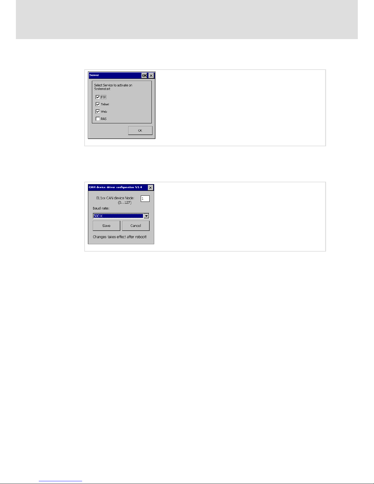
8.2.5 Server 44 . . . . . . . . . . . . . . . . . . . . . . . . . . . . . . . . . . . . . . . . . . . . . . . . . . . . . . .
8.2.6 Fieldbus 44 . . . . . . . . . . . . . . . . . . . . . . . . . . . . . . . . . . . . . . . . . . . . . . . . . . . . .
8.2.7 MPI Configuration 45 . . . . . . . . . . . . . . . . . . . . . . . . . . . . . . . . . . . . . . . . . . . .
8.2.8 CAN Gateway 45 . . . . . . . . . . . . . . . . . . . . . . . . . . . . . . . . . . . . . . . . . . . . . . .
8.3 Creating a PLC sample program 49 . . . . . . . . . . . . . . . . . . . . . . . . . . . . . . . . . . . . . . . .
8.3.1 General information on PLC programming 49 . . . . . . . . . . . . . . . . . . . . . . .
8.3.2 Start PLC Designer 50 . . . . . . . . . . . . . . . . . . . . . . . . . . . . . . . . . . . . . . . . . . . .
8.3.3 Create PLC program 50 . . . . . . . . . . . . . . . . . . . . . . . . . . . . . . . . . . . . . . . . . . .
8.3.4 Create sym file 53 . . . . . . . . . . . . . . . . . . . . . . . . . . . . . . . . . . . . . . . . . . . . . . .
8.3.5 Transfer program to HMI 55 . . . . . . . . . . . . . . . . . . . . . . . . . . . . . . . . . . . . . .
8.3.6 Start program on HMI 57 . . . . . . . . . . . . . . . . . . . . . . . . . . . . . . . . . . . . . . . . .
8.3.7 Build up CAN communication with distributed I/O module 57 . . . . . . . . .
8.4 Access EL 1xx via server functionality 62 . . . . . . . . . . . . . . . . . . . . . . . . . . . . . . . . . . . .
8.4.1 Enable Server Access 63 . . . . . . . . . . . . . . . . . . . . . . . . . . . . . . . . . . . . . . . . .
8.4.2 FTP Server − Transmit Data 65 . . . . . . . . . . . . . . . . . . . . . . . . . . . . . . . . . . . . .
8.4.3 Web Server (SysAdmin) − Manage Processes, Files, Registry 65 . . . . . . . . . .
8.4.4 Telnet Server − Manage files at the Windows Command Prompt 66 . . . . .
8.4.5 VNC−Server − Operate the EL 1xx by remote control via Internet or LAN 67
8.4.6 RAS Server − Operate your EL 1xx by remote control via telephone line 68
Page 5

Contents i
5
LDCDS−EL100 EN 8.0
8.5 Communicating via the CAN gateway function 69 . . . . . . . . . . . . . . . . . . . . . . . . . . . .
8.5.1 Important notes 69 . . . . . . . . . . . . . . . . . . . . . . . . . . . . . . . . . . . . . . . . . . . . . .
8.5.2 Establishing communication using the system bus configurator 69 . . . . . .
8.5.3 Establishing communication using the Global Drive Control (GDC) 73 . . .
8.5.4 Establishing communication using the L−force Engineer 75 . . . . . . . . . . . .
8.5.5 Establishing communication using the Drive PLC Developer
Studio (DDS) 78 . . . . . . . . . . . . . . . . . . . . . . . . . . . . . . . . . . . . . . . . . . . . . . . . .
9 Maintenance 80 . . . . . . . . . . . . . . . . . . . . . . . . . . . . . . . . . . . . . . . . . . . . . . . . . . . . . . . . . . . . .
9.1 General notes 80 . . . . . . . . . . . . . . . . . . . . . . . . . . . . . . . . . . . . . . . . . . . . . . . . . . . . . . .
9.2 Battery replacement 80 . . . . . . . . . . . . . . . . . . . . . . . . . . . . . . . . . . . . . . . . . . . . . . . . . .
10 Index 82 . . . . . . . . . . . . . . . . . . . . . . . . . . . . . . . . . . . . . . . . . . . . . . . . . . . . . . . . . . . . . . . . . . . .
Page 6
About this documentation
Validity information
1
6
LDCDS−EL100 EN 8.0
0Fig. 0Tab. 0
1 About this documentation
1.1 Validity information
These instructions are valid for
HMI with CAN interface HMI with CAN interface, integrated
PLC and UPS
HMI with MPI interface
EL 103 ECO EL 103 ECO PLC −
EL 105M CAN EL 105m PLC EL 105M MPI
EL 105 CAN EL 105 PLC EL 105 MPI
EL 106 CAN EL 106 PLC EL 106 MPI
EL 108 CAN EL 108 PLC EL 108 MPI
EL 110 CAN EL 110 PLC EL 110 MPI
EL 110s CAN EL 110s PLC EL 110s MPI
The nameplate is on the back of the device.
1.2 Target group
This documentation is directed at qualified skilled personnel according to IEC 60364.
Qualified skilled personnel are persons who have the required qualifications to carry out
all activities involved in installing, mounting, commissioning, and operating the product.
Page 7
About this documentation
Document history
1
7
LDCDS−EL100 EN 8.0
1.3 Document history
Material number Version Description
13200039 1.0 03/2007 TD29 First edition
13227672 2.0 11/2007 TD29 The "Commissioning" chapter has been expanded by
descriptions on server functionalities
13236340 3.0 04/2008 TD29 Description of type EL 110s and all types with
integrated PLC has been added
13273430 4.0 01/2009 TD29 Amended by description of type EL 112
13327978 5.0 05/2010 TD29 Amended by description of type EL 103 ECO;
description of type EL 112 deleted; adapted BA
according to the new specifications regarding the
Lenze classification and the new specifications of
the units of measurement regulation
13346004 6.0 08/2010 TD29 Corrected CAN connection drawing for EL 103 ECO
13349601 7.0 06/2011 TD29 UL approval and other revisions
13349601 7.1 07/2011 TD29 Pin assignment SUB−D plug corrected
.Hv| 8.0 01/2012 TD29 New chapter "Install fonts"
Tip!
Information and auxiliary devices around the Lenze products can be found in
the download area at
http://www.Lenze.com
1.4 Terminology used
Term In the following text used for
EL 1xx HMI of the EL 100 or EL 100 ECO series
HMI Human Machine Interface
MPI Interface for the SIMATIC S7 automation system from Siemens AG
SD/SDHC card Memory card in the SD/SDHC format
Touchscreen Touch screen terminal
1.5 Conventions used
Type of information Identification Examples/notes
Spelling of numbers
Decimal separator
Point In general, the decimal point is used.
For instance: 1234.56
Text
Program name » « PC software
For example: »Engineer«, »Global Drive
Control« (GDC)
Icons
Page reference Reference to another page with additional
information
For instance: 16 = see page 16
Page 8

About this documentation
Notes used
1
8
LDCDS−EL100 EN 8.0
1.6 Notes used
The following pictographs and signal words are used in this documentation to indicate
dangers and important information:
Safety instructions
Structure of safety instructions:
Danger!
(characterises the type and severity of danger)
Note
(describes the danger and gives information about how to prevent dangerous
situations)
Pictograph and signal word Meaning
Danger!
Danger of personal injury through dangerous electrical voltage.
Reference to an imminent danger that may result in death or
serious personal injury if the corresponding measures are not
taken.
Danger!
Danger of personal injury through a general source of danger.
Reference to an imminent danger that may result in death or
serious personal injury if the corresponding measures are not
taken.
Stop!
Danger of property damage.
Reference to a possible danger that may result in property
damage if the corresponding measures are not taken.
Application notes
Pictograph and signal word Meaning
Note!
Important note to ensure troublefree operation
Tip!
Useful tip for simple handling
Reference to another documentation
Page 9

Safety instructions
General safety instructions
2
9
LDCDS−EL100 EN 8.0
2 Safety instructions
2.1 General safety instructions
Danger!
Disregarding the following basic safety measures may lead to severe personal
injury and damage to material assets!
ƒ Lenze drive and automation components ...
... must only be used for the intended purpose.
... must never be operated if damaged.
... must never be subjected to technical modifications.
... must never be operated unless completely assembled.
... must never be operated without the covers/guards.
... can − depending on their degree of protection − have live, movable or rotating parts
during or after operation. Surfaces can be hot.
ƒ For Lenze drive components ...
... only use permitted accessories.
... only use original manufacturer spare parts.
ƒ All specifications of the corresponding enclosed documentation must be observed.
This is vital for a safe and trouble−free operation and for achieving the specified product
features.
The procedural notes and circuit details provided in this document are proposals which
the user must check for suitability for his application. The manufacturer does not
accept any liability for the suitability of the specified procedures and circuit proposals.
ƒ Only qualified skilled personnel are permitted to work with or on Lenze drive and
automation components.
According to IEC 60364 or CENELEC HD 384, these are persons ...
... who are familiar with the installation, assembly, commissioning and operation of
the product,
... possess the appropriate qualifications for their work,
... and are acquainted with and can apply all the accident prevent regulations, directives
and laws applicable at the place of use.
Transport, storage
ƒ Transport and storage in a dry, low−vibration environment without aggressive
atmosphere; preferably in the packaging provided by the manufacturer.
– Protect against dust and shocks.
– Comply with climatic conditions according to the technical data.
Page 10

Safety instructions
General safety instructions
2
10
LDCDS−EL100 EN 8.0
Mechanical installation
ƒ Install the product according to the regulations of the corresponding
documentation. In particular observe the section "Operating conditions" in the
chapter "Technical data".
ƒ Provide for a careful handling and avoid mechanical overload. During handling
neither bend components, nor change the insulation distances.
ƒ The product contains electrostatic sensitive devices which can easily be damaged by
short circuit or static discharge (ESD). Thus, electronic components and contacts
must not be touched unless ESD measures are taken beforehand.
Electrical installation
ƒ Carry out the electrical installation according to the relevant regulations (e. g. cable
cross−sections, fusing, connection to the PE conductor). Additional notes are
included in the documentation.
ƒ When working on live products, observe the applicable national regulations for the
prevention of accidents (e.g. BGV 3).
ƒ The documentation contains information about EMC−compliant installation
(shielding, earthing, arrangement of filters and laying cables). The system or
machine manufacturer is responsible for compliance with the limit values required
by EMC legislation.
Warning: The controllers are products which can be used in category C2 drive systems
as per EN 61800−3. These products may cause radio interference in residential areas. If
this happens, the operator may need to take appropriate action.
ƒ For compliance with the limit values for radio interference emission at the site of
installation, the components − if specified in the technical data − have to be mounted
in housings (e. g. control cabinets). The housings have to enable an EMC−compliant
installation. In particular observe that for example control cabinet doors preferably
have a circumferential metallic connection to the housing. Reduce openings or
cutouts through the housing to a minimum.
ƒ Only plug in or remove pluggable terminals in the deenergised state!
Commissioning
ƒ If required, you have to equip the system with additional monitoring and protective
devices in accordance with the respective valid safety regulations (e. g. law on
technical equipment, regulations for the prevention of accidents).
Maintenance and servicing
ƒ The components are maintenance−free if the required operating conditions are
observed.
ƒ If the cooling air is polluted, the cooling surfaces may be contaminated or the air
vents may be blocked. Under these operating conditions, the cooling surfaces and air
vents must be cleaned at regular intervals. Never use sharp objects for this purpose!
ƒ After the system has been disconnected from the supply voltage, live components
and power connections must not be touched immediately because capacitors may
be charged. Please observe the corresponding notes on the device.
Page 11

Safety instructions
Product−specific safety instructions
2
11
LDCDS−EL100 EN 8.0
Disposal
ƒ Recycle metals and plastic materials. Ensure professional disposal of assembled
PCBs.
ƒ This device contains a battery. According to European legislation you are obliged to
dispose of batteries separately via the take−back systems specified.
2.2 Product−specific safety instructions
ƒ Before working on the HMI, the supply connector must be unplugged. This is
particularly important before opening the enclosure and connecting/removing
connectors.
ƒ The voltage input is not internally fused and may be destroyed if the input voltage is
too high. Observe the maximally permissible input voltage and professionally fuse
the device on the input side against voltage fluctuations and peaks.
ƒ During installation, see that the maximally permissible ambient temperature is not
exceeded. Corresponding measures for active or passive cooling must be taken if
required.
ƒ The HMI is a device of class A and can cause radio interference in residential areas. In
this case, the operator may have to take special measures. Any costs arising from
these measures have to be paid by the operator.
ƒ In the case of an error, send the HMI to the manufacturer. The address is provided on
the return envelope of this documentation. Please use the original packaging if you
return the HMI!
Page 12

Product description
Application as directed
3
12
LDCDS−EL100 EN 8.0
3 Product description
3.1 Application as directed
HMIs of the EL 1xx series
ƒ are Human Machine Interfaces (HMIs) for the implementation of operating concepts
or the provision of information in common industrial and commercial areas.
ƒ must only be operated if the operating conditions specified in these operating
instructions are met.
ƒ are no household appliances. They are components intended to be used exclusively
for commercial purposes.
Systems with HMI devices
ƒ The user is responsible for the compliance of his application with the EC Directives.
Any other use shall be deemed inappropriate!
A use that is not intended also includes a use harbouring fatal risks or dangers which,
without the provision of exceptionally high safety measures, may result in death, injury or
damage to material assets.
The HMI must in particular not be used ...
ƒ in private areas.
ƒ in potentially explosive atmosphere.
ƒ in areas with harmful gases, oils, acids, radiation, etc.
ƒ for performing safety functions, for instance
– in air traffic control / in flight−control systems
– for the monitoring/control of nuclear reactions
– for the monitoring/control of means of mass transport
– for the monitoring/control of medical systems
– for the monitoring/control of weapons systems
Higher−level safety systems must be used to guarantee the protection of persons and
material assets!
Note!
The touchscreen does not comply with the Ergonomics Directive ZH 1/618.
Therefore, it is only designed for short−time inputs and monitoring functions.
For longer inputs, connect an external keyboard.
Page 13
Product description
Scope of supply
EL 1xx CAN/PLC/MPI
3
13
LDCDS−EL100 EN 8.0
3.2 Scope of supply
Number Description
1 HMI
4
4
4
6
8
Screw clamp fixings
for EL 103 ECO (PLC)
for EL 105(m) CAN/PLC/MPI
for EL 106 CAN/PLC/MPI
for EL 108 CAN/PLC/MPI
for EL 110(s) CAN/PLC/MPI
1 Mounting instructions
1 DVD "L−force PC−based Automation"
3.3 Overview
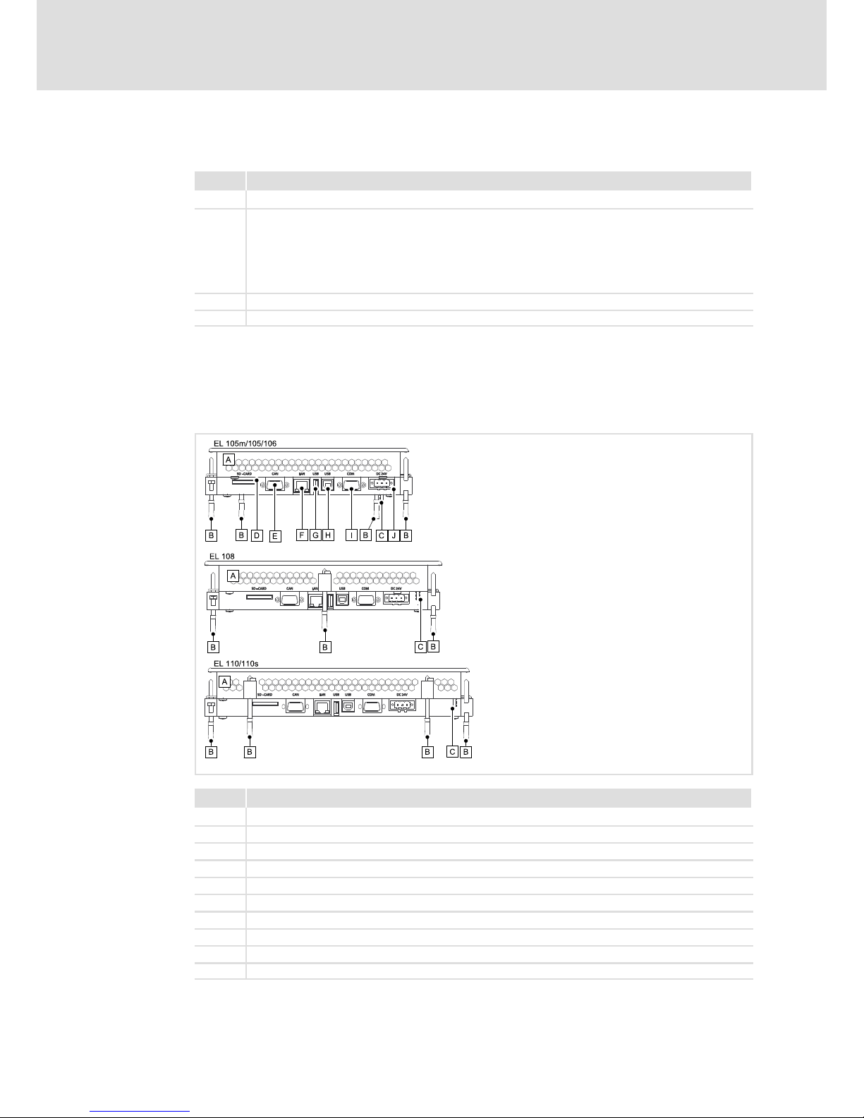
3.3.1 EL 1xx CAN/PLC/MPI
EL100−001
Pos. Description
HMI
Screw clamp fixings
PE connection
SD/SDHC card slot
CAN or MPI port
Ethernet port
USB−A port
USB−B port
Serial RS232 interface
Connection supply
Page 14

Product description
Overview
EL 1xx ECO (PLC)
3
14
LDCDS−EL100 EN 8.0
3.3.2 EL 1xx ECO (PLC)
EL100e−001
Pos. Description
HMI
Screw clamp fixings
PE connection
SD/SDHC card slot
CAN interface
Ethernet port
USB−A port
Connection supply
SD/SDHC card protection (eject protection)
Page 15
Technical data
General data and operating conditions
4
15
LDCDS−EL100 EN 8.0
4 Technical data
4.1 General data and operating conditions
Conformity and approval
Conformity
CE
EN 61000 6−1(3),
VDE 0839 6−1(3)
2002 residential area
EN 61000 6−2(4),
VDE 0839 6−2(4)
2006 industrial premises
EN 55022
EN 55024 Equipment of information technology
Approbation
UL UL 508
CSA C22.2
Programmable Controllers (File−No. E236341)
Protection of persons and equipment
Type of protection
IP65 (front) / IP20 (back)
UL type ratings 1, 2 and 5
Ambient conditions
Climatic
Storage 0 ... +60 °C
Transport 0 ... +60 °C
Operation
EL 1xx ECO
EL 1xx CAN/MPI
0 ... +50 °C
EL 1xx ECO PLC
EL 1xx PLC
5 ... +45 °C
Relative humidity 10 ... 90 %, no condensation
Site altitude < 3000 m amsl
Vibration test according to EN 61131−2 (programmable controllers)
Vibration EN 60068−2−6 1 g
Shock EN 60068−2−27 15 g
Mounting conditions
Mounting place
Control cabinet door
Mounting position Terminals at the bottom
Page 16

Technical data
Electrical data
EL 1xx CAN/PLC/MPI
4
16
LDCDS−EL100 EN 8.0
4.2 Electrical data
4.2.1 EL 1xx CAN/PLC/MPI
Supply
Type EL xxx
105m 105 106 108 110 110s
Voltage [V] DC 24 (+18 ... 30)
Current at 24 V [A] 0.25 0.3 0.3 0.5 0.5
Power at 24 V [W] 6.0 7.2 7.2 12.0 12.0
Buffer for real−time clock
dated
Typ EL xxx
105m 105 106 108 110 110s
Battery
Service life
[year] 7 (at 25 °C)
CPU and operating system
Typ EL xxx
105m 105 106 108 110 110s
CPU type IntelR Xscale PXA 270
Operating
system
WindowsR CE 5.0
Memory
Typ EL xxx CAN/MPI
105m 105 106 108 110 110s
RAM [MB] 64
Flash [MB] 32
Exchangeable
disk storage
SD/SDHC card slot
1)
Memory
Typ EL xxx PLC
105m 105 106 108 110 110s
RAM [MB] 128
Flash [MB] 64
Exchangeable
disk storage
SD/SDHC card slot
1)
1)
Due to the great variety of SD/SDHC cards available on the market, compatibility cannot be ensured. We do not
know about any restrictions.
Page 17
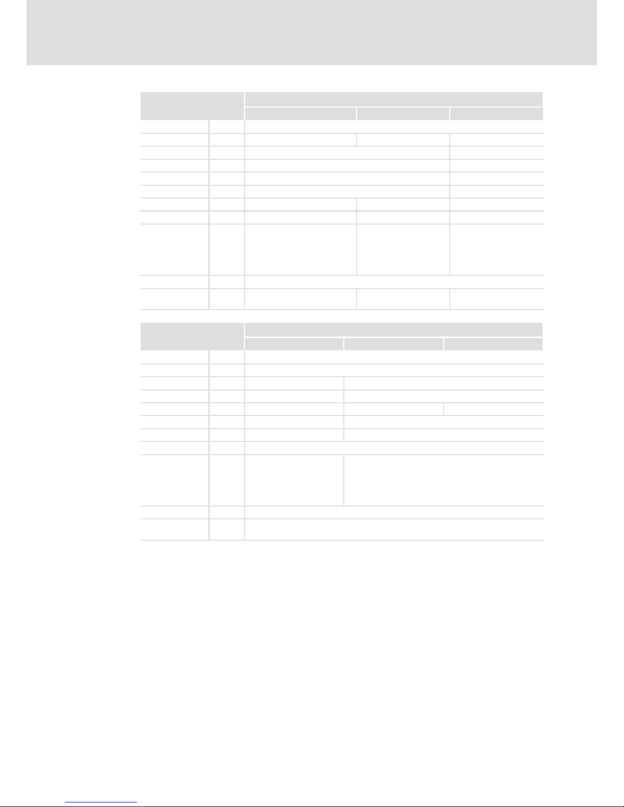
Technical data
Electrical data
EL 1xx CAN/PLC/MPI
4
17
LDCDS−EL100 EN 8.0
Screen
Typ EL xxx
105m 105 106
Type Touch screen, resistive
Colours 16 grey tones 64 K 64 K
Display diagonal [cm] 14.5 (5.7") 16.3 (6.4")
Visible size [mm] 115 x 86 131 x 98
Resolution [pixels] 320 x 240 640 x 480
Pixel size [mm] 0.33 x 0.33 0.07 x 0.07
Contrast − 400:1 400:1
Brightness [cd/m2] 180 250 250
Angle of view
right
left
top
bottom
[°] −
−
−
−
60
60
40
50
65
65
50
60
Illumination Cathode−ray tube, adjustable
Service life at
25°C
[h] 40000 45000 50000
Screen (continued)
Typ EL xxx
108 110 110s
Type Touch screen, resistive
Colours 64 K
Display diagonal [cm] 20.3 (8") 26.4 (10.4")
Visible size [mm] 162 x 122 216 x 163
Resolution [pixels] 640 x 480 640 x 480 600 x 800
Pixel size [mm] 0.25 x 0.25 0.33 x 0.33
Contrast 250:1 300:1
Brightness [cd/m2] 400
Angle of view
right
left
top
bottom
[°] 65
65
55
65
60
60
40
50
Illumination Cathode−ray tube, adjustable
Service life at
25°C
[h] 50000
Page 18
Technical data
Electrical data
EL 1xx CAN/PLC/MPI
4
18
LDCDS−EL100 EN 8.0
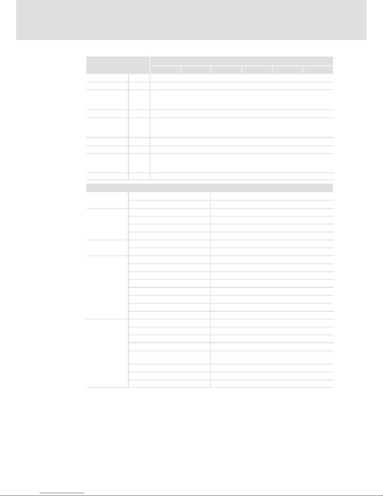
PLC functions
(EN 61131−3)
Typ EL xxx PLC
105m 105 106 108 110 110s
Editor AWL, FUP, KOP, ST, AS, CFC
Program code [kB] 2048
Data memory
Variables
Global Var.
[kB]
[kB]
1024
512
Memory location [kB] 4
Process image
Input
Output
[kB]
[kB]
4
4
Retain data [kB] 128
UPS Integrated to save retain data to the flash memory
Target
L−force Logic
EL1xx
V1.x
Task runtime [ms] ³10
Ports
COM 1
Type
RS232
Connection SUB−D, 9−pole, connector
LAN
Type Ethernet
Protocol TCP/IP
Baud rate 10/100 Mbits
Connection RJ45, socket
USB
Type 2.0 (1.1−compatible)
Connection Type A and type B, socket
CAN
1)
Type CAN, ISO11898
Protocol Lenze system bus CAN
Topology Line, terminated on both sides with 120 W
Node Master or slave
Number of nodes Max. 63
Baud rate See CAN communication manual
Bus length See CAN communication manual
Connection SUB−D, 9−pole, connector
MPI
1)
Type RS485
Protocol MPI
Topology Line, terminated on both sides with 200 W
Node Master
Number of nodes Max. 32 per segment
Max. 127 with RS485 repeaters
Baud rate 19.2 kBaud ... 12 MBaud
Bus length Max. 50 m
Connection SUB−D, 9−pole, connector
1
* optionally CAN or MPI
Page 19
Technical data
Electrical data
EL 1xx ECO (PLC)
4
19
LDCDS−EL100 EN 8.0
4.2.2 EL 1xx ECO (PLC)
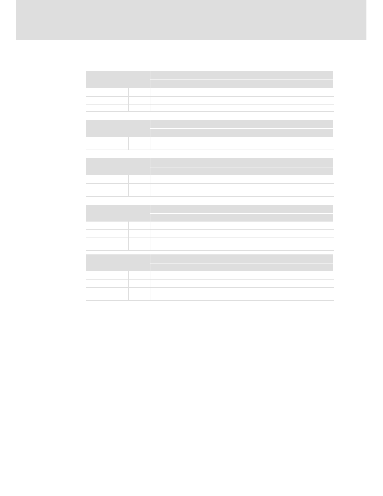
Supply
Type EL xxx ECO
103
Voltage [V] DC 24 (+18 ... 30)
Current at 24 V [A] 0.21
Power at 24 V [W] 5.0
Buffer for real−time clock
dated
Typ EL xxx ECO
103
Capacitor
Max. buffer time
[week]
2
CPU and operating system
Typ EL xxx ECO
103
CPU type IntelR Xscale PXA 270
Operating
system
WindowsR CE 5.0
Memory
Typ EL xxx ECO CAN
103
RAM [MB] 64
Flash [MB] 32
Exchangeable
disk storage
SD/SDHC card slot
1)
Memory
Typ EL xxx ECO PLC
103
RAM [MB] 64
Flash [MB] 32
Exchangeable
disk storage
SD/SDHC card slot
1)
1)
Due to the great variety of SD/SDHC cards available on the market, compatibility cannot be ensured. We do not
know about any restrictions.
Page 20
Technical data
Electrical data
EL 1xx ECO (PLC)
4
20
LDCDS−EL100 EN 8.0
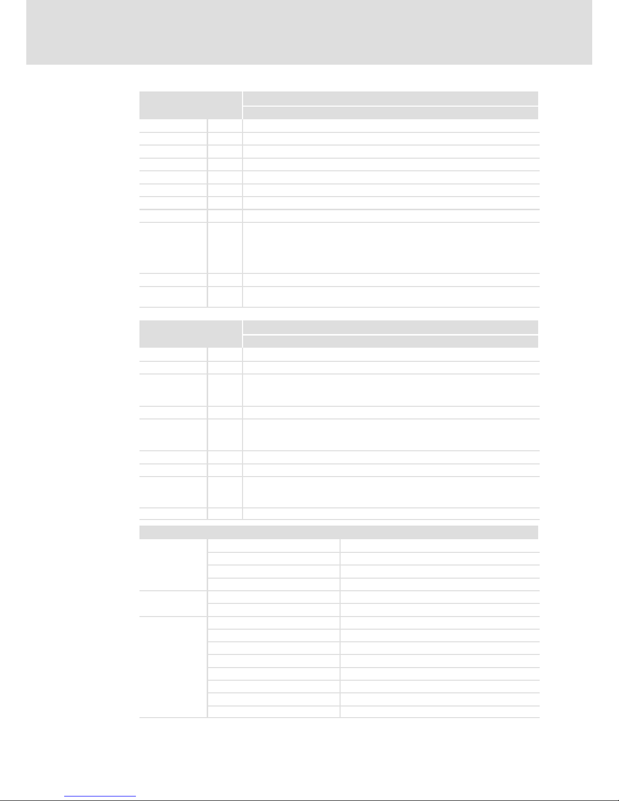
Screen
Typ EL xxx ECO
103
Type Touch screen, resistive
Colours 64 K
Display diagonal [cm] 8.9 (3.5")
Visible size [mm] 70 x 53
Resolution [pixels] 320 x 240
Pixel size [mm] 0.7 x 0.22
Contrast 400:1
Brightness [cd/m2] 300
Angle of view
right
left
top
bottom
[°] 65
65
50
60
Illumination LED
Service life at
25°C
[h] −
PLC functions
(EN 61131−3)
Typ EL xxx ECO PLC
103
Editor AWL, FUP, KOP, ST, AS, CFC
Program code [kB] 256
Data memory
Variables
Global Var.
[kB]
[kB]
64
64
Memory location [kB] 4
Process image
Input
Output
[kB]
[kB]
1
1
Retain data [kB] 16
UPS Integrated to save retain data to the flash memory
Target
L−force Logic
EL1xx
V2.x
Task runtime [ms] ³100
Ports
LAN
Type
Ethernet
Protocol TCP/IP
Baud rate 10/100 Mbits
Connection RJ45, socket
USB
Type 2.0 (1.1−compatible)
Connection Type A, socket
CAN
Type CAN, ISO11898
Protocol Lenze system bus CAN
Topology Line, terminated on both sides with 120 W
Node Master or slave
Number of nodes Max. 63
Baud rate See CAN communication manual
Bus length See CAN communication manual
Connection SUB−D, 9−pole, connector
Page 21
Technical data
Mechanical data
EL 1xx CAN/PLC/MPI
4
21
LDCDS−EL100 EN 8.0
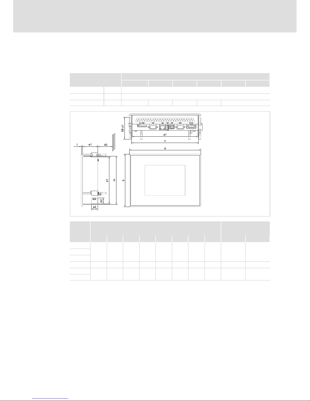
4.3 Mechanical data
4.3.1 EL 1xx CAN/PLC/MPI
Design and weight
Type EL xxx
105m 105 106 108 110 110s
Front Aluminium with polyester film to DIN 42115
Cover Sheet steel, galvanised
Weight [kg] 1.1 1.1 1.2 1.5 2.0
EL100−002
Type
Dimensions Mounting cutout
[mm] [mm]
a a1 b b1 b2 e1 e2 t n ±0.5 m ±0.5
EL 105
210
193 155 138 17.5 43.6 17.6 4 197 142
EL 105M
EL 106
EL 108 250 220 180 156.5 33.7 46 18 4 224 160.5
EL 110
275 257 220 201 75.5 46 18 4 261 205
EL 110s
Page 22
Technical data
Mechanical data
EL 1xx ECO (PLC)
4
22
LDCDS−EL100 EN 8.0
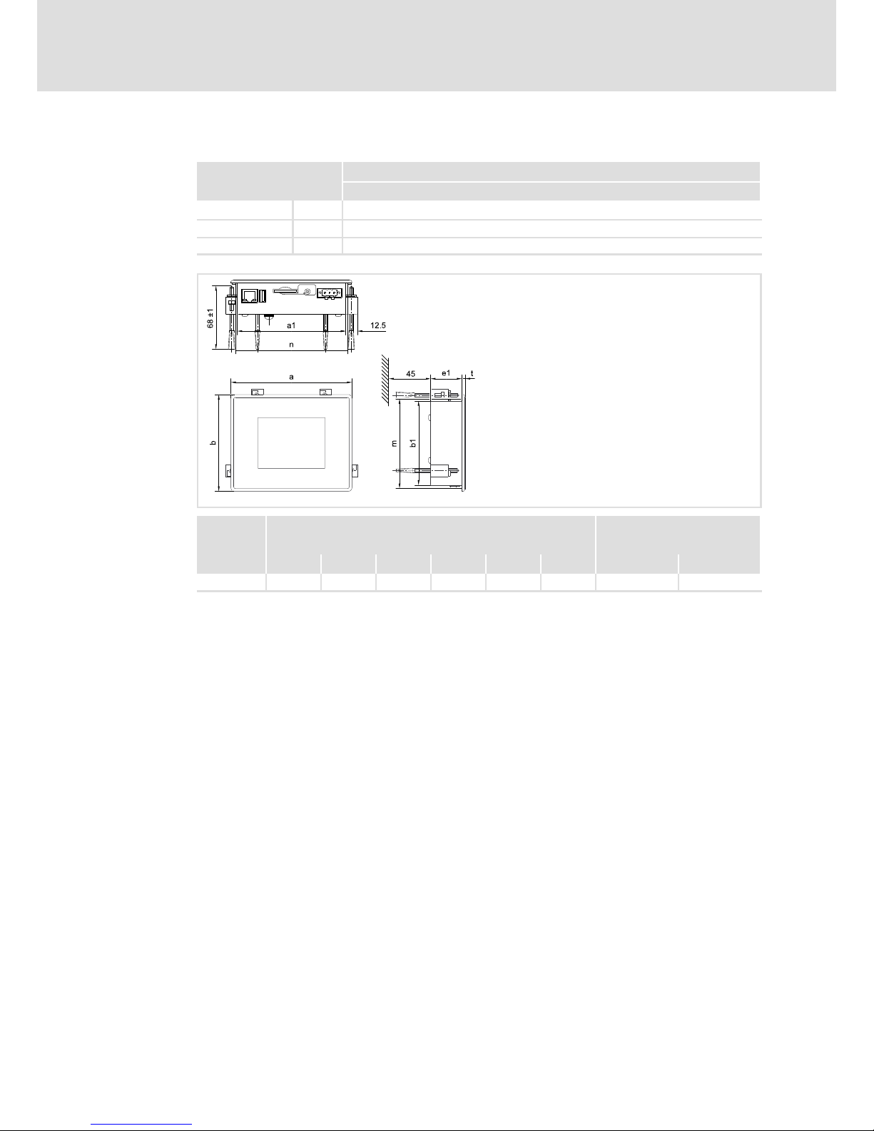
4.3.2 EL 1xx ECO (PLC)
Design and weight
Type EL xxx ECO
103
Front Aluminium with polyester film to DIN 42115
Cover Sheet steel, galvanised
Weight [kg] 0.4
EL100e−002
Type
Dimensions Mounting cutout
[mm] [mm]
a a1 b b1 e1 t n ±0.5 m ±0.5
EL 103 ECO 130 116.5 104 90.5 33.6 3 120 94
Page 23
Mechanical installation 5
23
LDCDS−EL100 EN 8.0
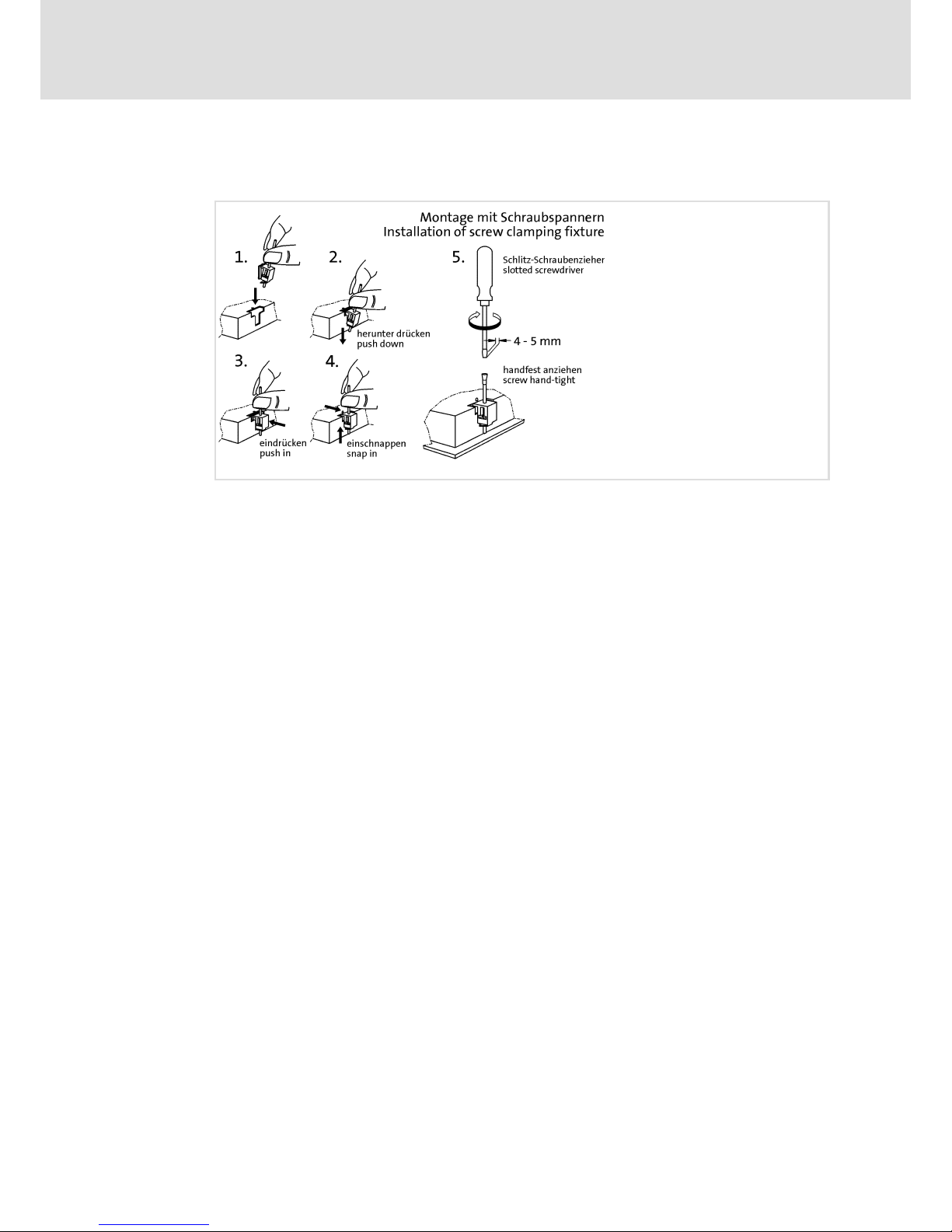
5 Mechanical installation
EL100−004
How to assemble the HMI:
1. Cut the mounting cutout out of the control cabinet door.
2. Assemble the upper screw clamping fixtures (see figure).
3. Check if the gasket under the front panel is located correctly.
4. Insert the device into the mounting cutout, secure it by hand against falling down
and tighten the assembled screw clamping fixtures hand−tight.
5. Secure the device by hand, assemble the remaining screw clamping fixtures and
tighten them hand−tight.
6. Check if the device is securely located in the mounting cutout and if the front panel
gasket is located correctly.
– If necessary, loosen the screw clamping fixtures, re−align the device or gasket and
tighten the screw clamping fixtures hand−tight.
– If the gasket is not located correctly, protection class IP65 is not reached on the
front of the device!
Page 24
Electrical installation
Important notes
6
24
LDCDS−EL100 EN 8.0
6 Electrical installation
6.1 Important notes
Stop!
No device protection against excessive input voltage
The voltage input is not fused internally.
Possible consequences:
ƒ The device can be destroyed when the input voltage is too high.
Protective measures:
ƒ Observe the max. permissible input voltage.
ƒ Professionally fuse the device on the input side against voltage fluctuations
and voltage peaks.
6.2 Wiring according to EMC
General notes l The electromagnetic compatibility of the system depends on the type and accuracy of the
installation. Please especially note the following:
– Structure
– Shielding
– Earthing
l In the case of a differing installation it is required for evaluating the conformity to the EMC
Directive to check the system with regard to compliance with the EMC limit values. This for
instance applies to:
– The use of unshielded cables
l The end user is responsible for compliance with the EMC Directive.
– If you observe the following measures, you can be sure that no EMC problems will occur
during operation and that the EMC Directive or the EMC law is met.
– If devices which do not meet the CE requirement with regard to noise immunity
EN 61000−4−2 are actuated near the system, these devices can be affected
electromagnetically by the system.
Structure l Connect device to the earthed mounting plate:
– Mounting plates with an electroconductive surface (zinc−coated or stainless steel) allow for
continuous contacting.
– Coated plates are not suitable for an EMC−compliant installation.
l If you use several mounting plates:
– Connect mounting plates to each other on a large surface and in a conductive manner (e.g.
by means of copper strips).
l When installing the cables, observe a spatial separation of signal and mains cables.
l Route the cables as near to the reference potential as possible. Freely suspended cables act
like aerials.
Shielding l Preferably only use cables with a braid.
l The coverage of the shield should be more than 80%.
l In the case of data lines for a serial coupling, always use metallic or metallised plugs. Connect
the shield of the data line on the connector shell.
Earthing l Earth all metallically conductive components by the use of corresponding cables from a
central earthing point (PE rail).
l Comply with the minimum cross−sections defined in the safety instructions:
– With regard to EMC, however, not the cable cross−section, but the surface of the cable and
of the extensive contacting is decisive.
Page 25

Electrical installation
Wiring
EL 1xx CAN/PLC/MPI
6
25
LDCDS−EL100 EN 8.0
6.3 Wiring
6.3.1 EL 1xx CAN/PLC/MPI
Mains connection
EL100−005
Description Connection type Cable type
0V U
DC 24 V connection
3−pole Phoenix Combicon
socket
Cable (conductor
cross−section max. 2.5 mm
2
)
with Phoenix Combicon plug,
MSTB 2.5 / 3−STF−5.08
IPC001
PE connection Threaded bolt M4
Separate earthing conductor
(min. 2.5 mm
2
) with ring
cable lug
IPC001
Page 26
Electrical installation
Wiring
EL 1xx CAN/PLC/MPI
6
26
LDCDS−EL100 EN 8.0
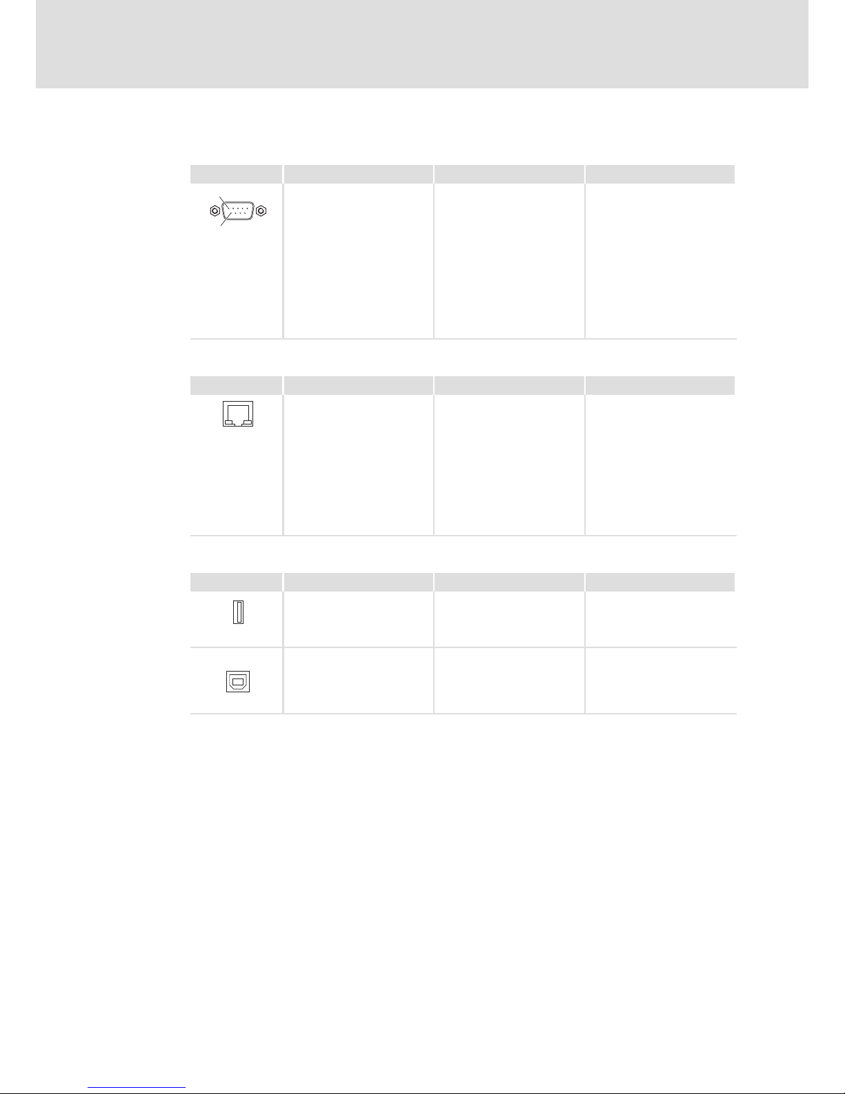
Serial interface
Description Connection type Cable type
6
1
RS232 connection
Pin 1: DCD
Pin 2: RxD
Pin 3: TxD
Pin 4: DTR
Pin 5: GND
Pin 6: DSR
Pin 7: RTS
Pin 8: CTS
Pin 9: RI
9−pin Sub−D plug
Control cable, shielded, with
9−pin Sub−D socket
IPC001
Ethernet interface
Description Connection type Cable type
Ethernet connection
10/100 Mbps
Green LED (SPEED):
on = 100 MBPS
off = 10 Mbps
Yellow LED (LINK/ACTIVITY):
on or blinking = LINK
/ACTIVITY
off = no LINK
RJ45 socket
Network cable CAT5 S/UTP or
CAT5e S/FTP (recommended),
cable length: max. 100 m
IPC001
USB interface
Description Connection type Cable type
USB 2.0 host connection
Max. load: 5 V/500 mA
USB−A socket USB cable with USB−A plug
IPC001
USB
USB device connection USB−B socket USB cable with USB−B plug
DVI/USB−010
Page 27

Electrical installation
Wiring
EL 1xx CAN/PLC/MPI
6
27
LDCDS−EL100 EN 8.0
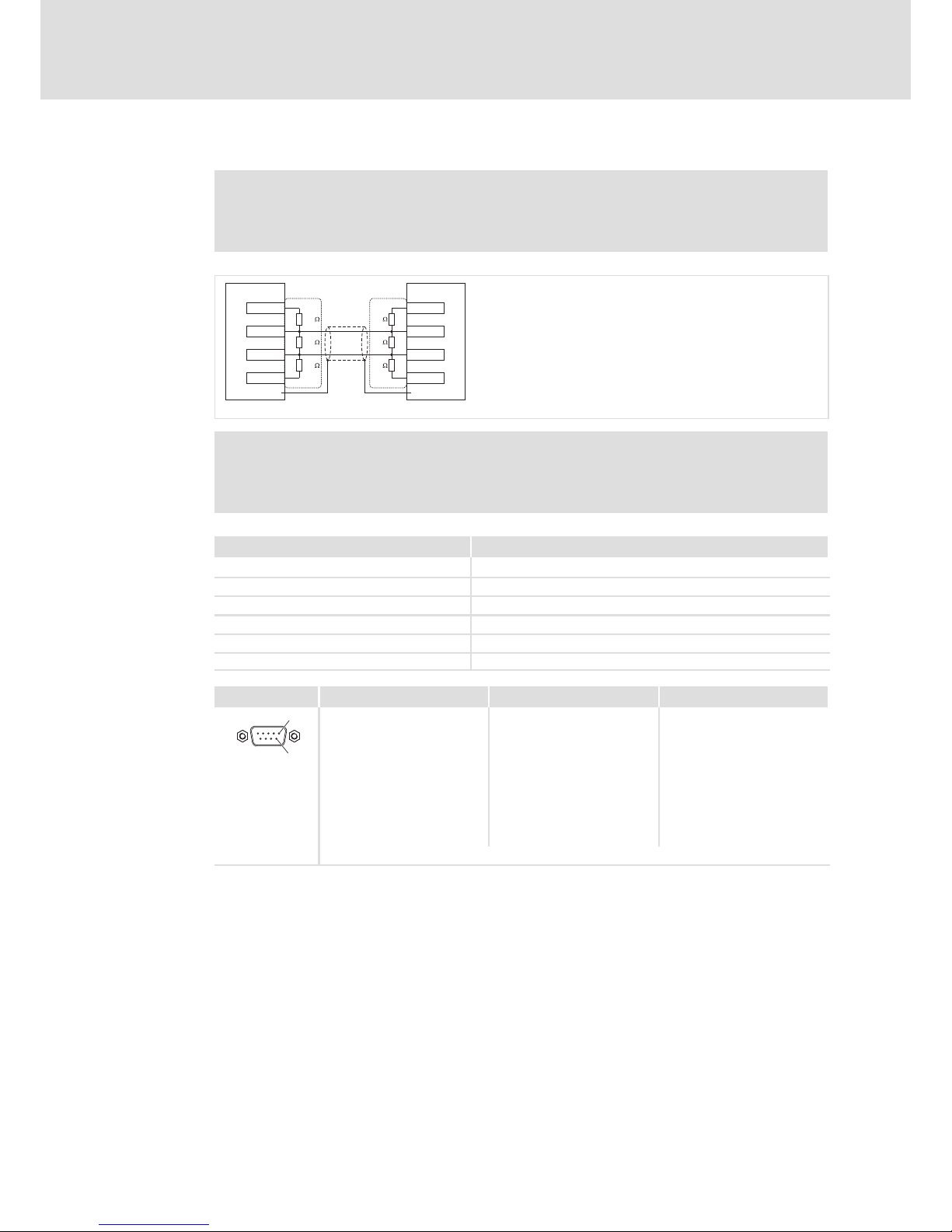
CAN interface
Note!
ƒ Only connect terminals of the same signal type.
ƒ For further information with regard to the CAN bus system please refer to
the CAN Communication Manual.
CG
CAN
LO HI CG
CAN
LO HI CG
CAN
LO HI
RR
A
n
A
2
A
1
EL100−009
A1 Node 1
A2 Node 2
An Node n
CG CAN−GND
LO CAN−LOW
HI CAN−HIGH
R 120 W−bus terminating resistor
We recommend the use of CAN cables in accordance with ISO 11898−2:
CAN cable in accordance with ISO 11898−2
Cable type Paired with shielding
Impedance 120 W (95 ... 140 W)
Cable resistance/cross−section
Cable length £ 300 m £ 70 mW/m / 0.25 0.34 mm2 (AWG22)
Cable length 301 1000 m £ 40 mW/m / 0.5 mm2 (AWG20)
Signal propagation delay £ 5 ns/m
Description Connection type Cable type
6
1
CAN bus connection
Pin 1: Not assigned
Pin 2: CAN−LOW (LO)
Pin 3: CAN−GND (CG)
Pin 4 ... 6: Not assigned
Pin 7: CAN−HIGH (HI)
Pin 8 ... 9: Not assigned
9−pole Sub−D plug
CAN cable acc. to ISO 11898−2
with 9−pole Sub−D socket
IPC001
Page 28
Electrical installation
Wiring
EL 1xx CAN/PLC/MPI
6
28
LDCDS−EL100 EN 8.0
MPI interface
Note!
ƒ For more information on the MPI port, please see the Siemens S7 System
Manual.
S7
EL1xx
RxD/TxD-P RxD/TxD-P
RxD/TxD-N RxD/TxD-N
M5V M5V
P5V
66
33
88
55
P5V
390 390
220 220
390 390
++
EL100−019
Note!
Only use cables complying with the listed specifications of the PROFIBUS user
organisation.
Field Values
Specific resistance 135 ... 165 W/km, (f = 3 ... 20 MHz)
Capacitance per unit length £ 30 nF/km
Loop resistance < 110 W/km
Core diameter > 0.64 mm
Core cross−section > 0.34 mm
2
Cores Twisted double, insulated and shielded
Description Connection type Cable type
6
1
MPI connection
Pin 1 ... 2: Not assigned
Pin 3: RxD/TxD−P (B)
Pin 4: RTS
Pin 5: M5V
Pin 6: P5V
Pin 7: Not assigned
Pin 8: RxD/TxD−N (A)
Pin 9: Not assigned
9−pole Sub−D socket
According to specification of
the Siemens company
IPC001
Cable fixing and strain relief
Realise external strain relief.
Page 29
Electrical installation
Wiring
EL 1xx ECO (PLC)
6
29
LDCDS−EL100 EN 8.0
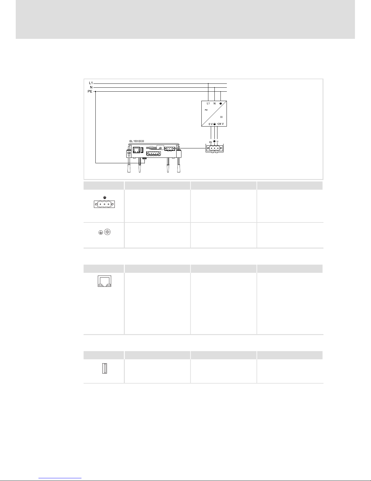
6.3.2 EL 1xx ECO (PLC)
Mains connection
EL100e−005
Description Connection type Cable type
0V U
DC 24 V connection
3−pole Phoenix Combicon
socket
Cable (conductor
cross−section max. 2.5 mm
2
)
with Phoenix Combicon plug,
MSTB 2.5 / 3−STF−5.08
IPC001
PE connection Screw M4
Separate earthing conductor
(min. 2.5 mm
2
) with ring
cable lug
IPC001
Ethernet interface
Description Connection type Cable type
Ethernet connection
10/100 Mbps
Green LED (SPEED):
on = 100 MBPS
off = 10 Mbps
Yellow LED (LINK/ACTIVITY):
on or blinking = LINK
/ACTIVITY
off = no LINK
RJ45 socket
Network cable CAT5 S/UTP or
CAT5e S/FTP (recommended),
cable length: max. 100 m
IPC001
USB interface
Description Connection type Cable type
USB 2.0 host connection
Max. load: 5 V/500 mA
USB−A socket USB cable with USB−A plug
IPC001
Page 30

Electrical installation
Wiring
EL 1xx ECO (PLC)
6
30
LDCDS−EL100 EN 8.0
CAN interface
Note!
ƒ Only connect terminals of the same signal type.
ƒ For further information with regard to the CAN bus system please refer to
the CAN Communication Manual.
CG
CAN
LO HI CG
CAN
LO HI CG
CAN
LO HI
RR
A
n
A
2
A
1
EL100−009
A1 Node 1
A2 Node 2
An Node n
CG CAN−GND
LO CAN−LOW
HI CAN−HIGH
R 120 W−bus terminating resistor
We recommend the use of CAN cables in accordance with ISO 11898−2:
CAN cable in accordance with ISO 11898−2
Cable type Paired with shielding
Impedance 120 W (95 ... 140 W)
Cable resistance/cross−section
Cable length £ 300 m £ 70 mW/m / 0.25 0.34 mm2 (AWG22)
Cable length 301 1000 m £ 40 mW/m / 0.5 mm2 (AWG20)
Signal propagation delay £ 5 ns/m
Description Connection type Cable type
CAN bus connection
Pin 1: CAN−GND (CG)
Pin 2: CAN−LOW (LO)
Pin 3: CAN−SHIELD
Pin 4: CAN−HIGH (HI)
Pin 5: Not assigned
5−pole Phoenix Combicon
socket
CAN cable acc. to ISO 11898−2
with Phoenix Combicon plug,
MSTB 2.5 / 5−STF−5.08
EL100−011
CAN cable shield connection via cable clamp on the back of the device:
EL100−033
Cable fixing and strain relief
Fix the cable bundles on the back of the EL 103 using cable ties.
EL100−034
Page 31
Commissioning
Connecting external devices
7
31
LDCDS−EL100 EN 8.0
7 Commissioning
7.1 Connecting external devices
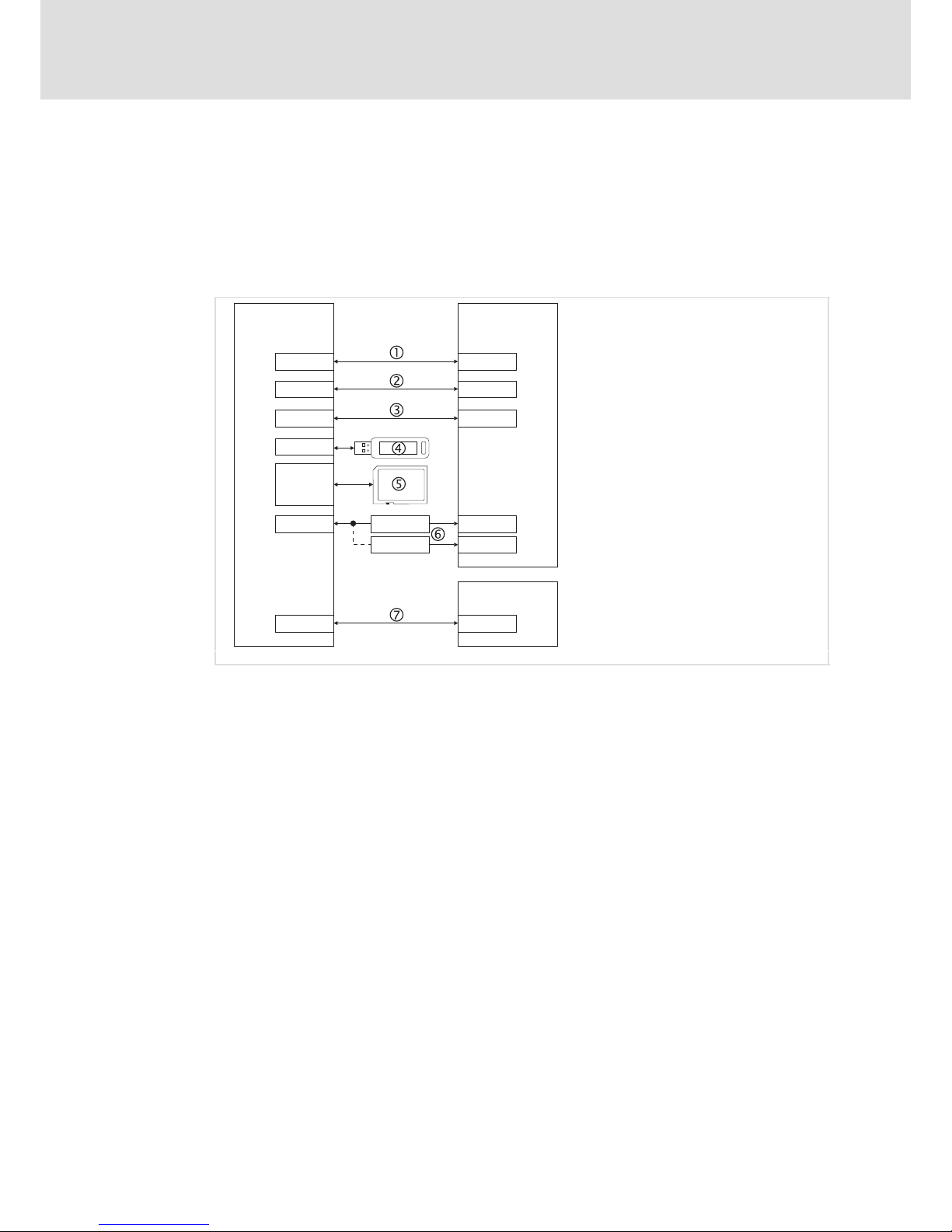
The HMI can communicate with other devices via different interfaces, e.g. to exchange
data or transfer projects:
EL 1xx PC
Simatic S7
LAN LAN
USB-B
1)
USB-A
USB-A
CAN
2)
MPI
2)
2177IB
2173IB
USB-A
MPI
LPT
COM1
1)
COM
SD/SDHC
EL100−016
1)
Not for EL 1xx ECO (PLC)
2)
Optionally CAN or MPI (EL 1xx ECO: CAN only)
EL 1xx « PC Ethernet connection, e.g. via cross−link cable
EL 1xx « PC USB connection device−host (the Microsoft
â
"ActiveSync" software must be
installed on the PC.)
EL 1xx « PC Serial connection via serial cross−link cable
USB stick, external keyboard/mouse
SD/SDHC card
EL 1xx « PC CAN bus connection with 2177IB (CAN to USB−A) or 2173IB (CAN to LPT
interface) PC bus adapter
EL 1xx « S7 MPI connection
Page 32

Commissioning
Initial switch−on
7
32
LDCDS−EL100 EN 8.0
7.2 Initial switch−on
How to proceed:
1. Check the whole wiring for completeness and correct installation.
For comprehensive inputs, we recommend to connect an external keyboard and mouse
to the USB port.
2. Switch on the voltage supply of the EL 1xx.
– The EL 1xx boots up, the operating system is started.
– If the EL 1xx is protected by a password, it will be queried.
– If the Show Explorer control field in the StartUp Control Panel Applet is marked
( 41), the Windows CE desktop will be displayed.
– If an autostart of the Remote Access Manager is specified in the VisiWinNET
â
Control Panel Applet ( 43), it will be started.
– If an autostart is specified for a project in the VisiWinNET
â
Control Panel Applet
( 43), it will be started.
Page 33
Commissioning
Establish Ethernet connection
Configure Ethernet interface
7
33
LDCDS−EL100 EN 8.0
7.3 Establish Ethernet connection
The EL 1xx can be connected to a LAN or to a PC directly (peer−to−peer) via Ethernet
interface.
7.3.1 Configure Ethernet interface
Prerequisite:
ƒ The EL 1xx is physically connected to the fieldbus via Ethernet interface.
– Network (with router): via Ethernet cable
– Peer−to−peer (without router): via crossed Ethernet cable (cross−over)
ƒ The EL 1xx is switched−on.
How to proceed:
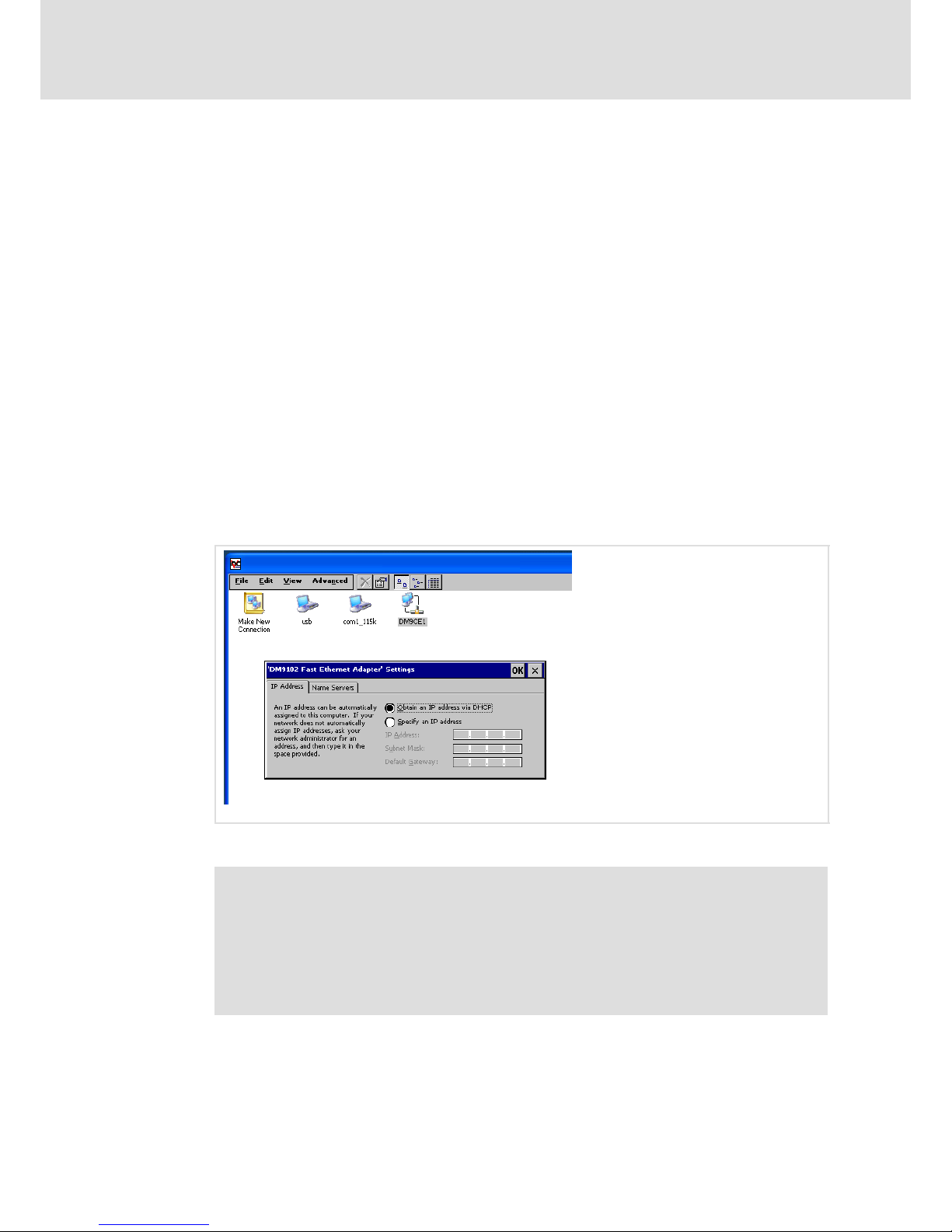
1. Click Start ® Settings ® Network and Dial−up Connections on your EL 1xx.
2. Click the Dm9CE1 connection and configure the following dialogue via network
interface.
EL100−021
3. Click OK.
Note!
Modifications are not stored automatically in the Registry. This means that
they will be lost after a restart.
If you wish to make permanent modifications, proceed as follows:
ƒ Click Start ® Settings ® Control Panel ® Registry on your EL 1xx.
ƒ Click Save.
4. If an IP address assignment via DHCP Server was specified when configuring the
interface (only available for networks with router), restart the EL 1xx.
5. Double−click the network symbol down right in the status bar and check the
settings.
Page 34

Commissioning
Establish Ethernet connection
Activate communication between EL 1xx and VisiWinNet
â
Smart
7
34
LDCDS−EL100 EN 8.0
7.3.2 Activate communication between EL 1xx and VisiWinNetâ Smart
The following settings are required if you wish to transmit a VisiWinNET
â
Smart project to
the EL 1xx via Ethernet. They are not required to establish a general TCP/IP connection.
How to proceed:
Note!
If an autostart of the Remote Access Manager is specified in the VisiWinNET
â
Control Panel Applet ( 43), the VisiWinNET Remote Access dialogue is
displayed automatically after starting the HMI.
Proceed as follows if that dialogue is not displayed:
ƒ Start ® Programs ® Windows Explorer
ƒ Folder Flashdisk/VisiWinNET
ƒ Double−click the VisiWinNET.RemoteAccessManager Application.
1. Activate the Commandhandler Registry in the VisiWinNET Remote Access Dialogue.
EL100−020
2. If the TCP/IP control field is selected and the status is displayed as Running,
communication has been enabled. Elsewise, proceed as follows:
3. Select the TCP/IP control field.
4. Click Start.
The status changes to Running. TCP/IP communication has been enabled.
5. Click Save to store this setting.
See VisiWinNET
â
Smart software manual, Getting Started, for further
information on project transmission.
Page 35
Commissioning
Establish CAN fieldbus connection
Configure CAN interface
7
35
LDCDS−EL100 EN 8.0
7.4 Establish CAN fieldbus connection
An EL 1xx CAN or EL 1xx ECO can be connected to a CAN fieldbus system via CAN interface.
7.4.1 Configure CAN interface
Prerequisite:
ƒ The EL 1xx is physically connected to the fieldbus via CAN interface.
ƒ The EL 1xx is switched−on.
How to proceed:
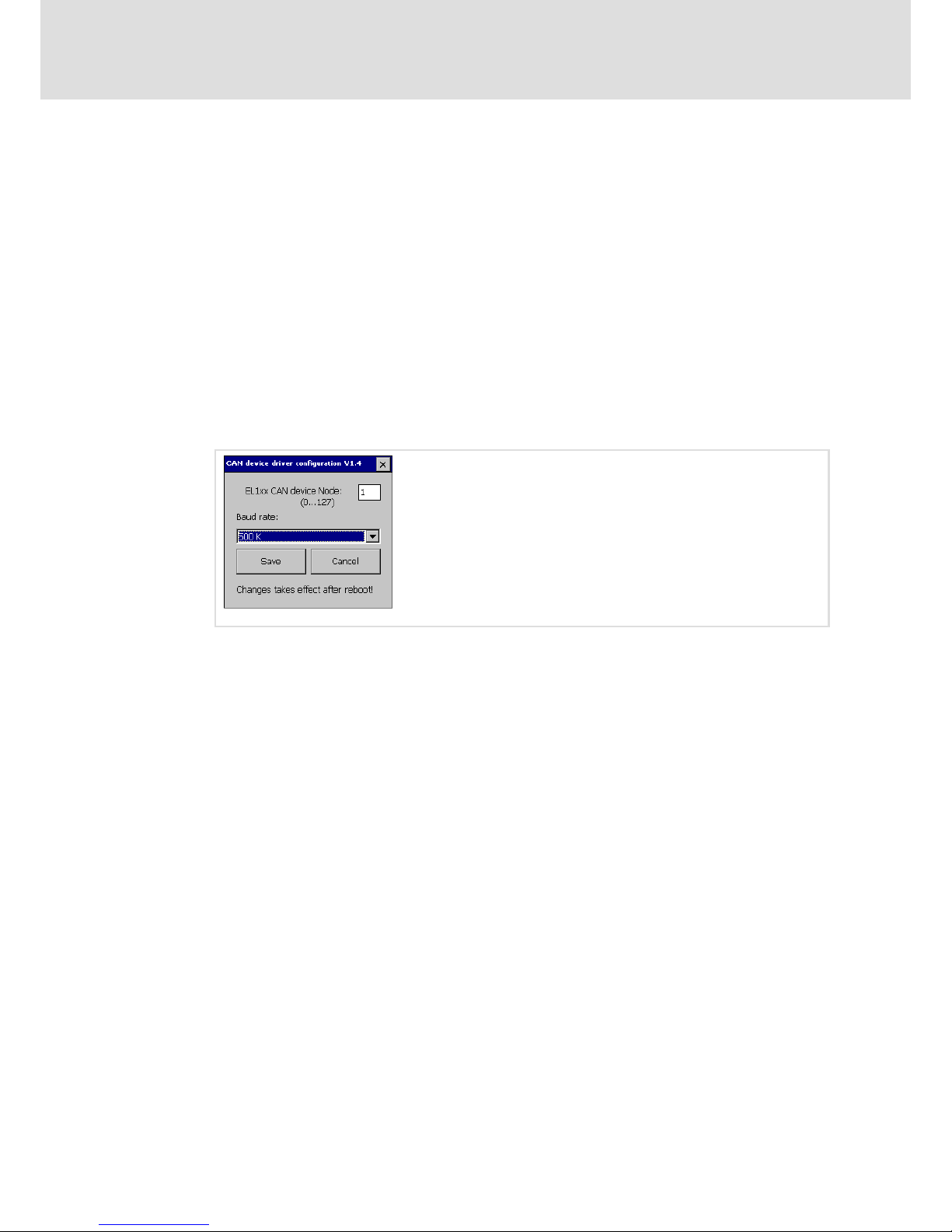
1. Click Start ® Settings ® Control Panel ® Fieldbus on the EL 1xx and configure the CAN
interface in the following dialogue.
EL100−028
EL 1xx CAN Device Node: The EL 1xx node address within a CAN fieldbus network.
Baud Rate: Transmission speed of the fieldbus. The baud rate must be identical for
each fieldbus node within the same network. The fieldbus parameters are set
according to the baud rate.
2. Click Save.
Page 36
Commissioning
Establish MPI connection
7
36
LDCDS−EL100 EN 8.0
7.5 Establish MPI connection
An EL1xx MPI is able to communicate with a S7 PLC via MPI (Multi Point Interface).
Prerequisite:
ƒ The EL 1xx is physically connected to the fieldbus via MPI interface.
ƒ The EL 1xx is switched−on.
How to proceed:
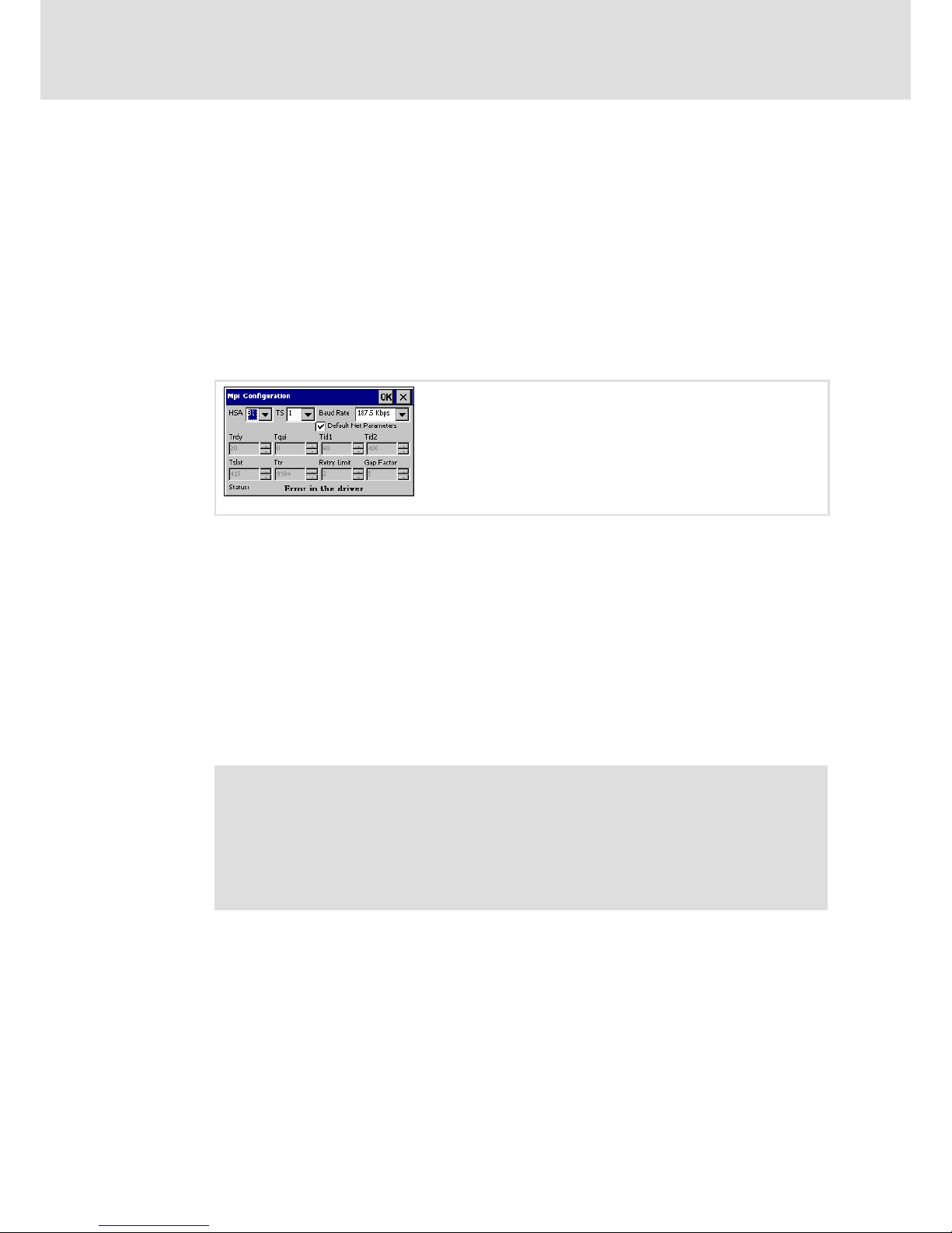
1. Click Start ® Settings.® Control Panel.® MPI Configuration on your EL 1xx.
The MPI Configuration Dialogue will be opened.
EL100−029
HSA: Set the highest MPI address (Highest Station Address) here. The highest MPI
address must be identical within an MPI network!
TS (This Station): Set the local MPI address for the EL 1xx here.
Baud Rate: Transmission speed of the MPI network. The baud rate must be identical
for each MPI node within the same network. The MPI parameters are set according to
the baud rate.
Default Net Parameters: Default Net Parameters specified due to the baud rate. We
recommend not to modify them.
Status: The status of the MPI interface is displayed as "Offline", "Online" or "Error" in
the status bar.
2. Click OK.
Note!
Modifications are not stored automatically in the Registry. This means that
they will be lost after a restart. If you wish to make permanent modifications,
proceed as follows:
ƒ Click Start ® Settings ® Control Panel ® Registry.
ƒ Click Save.
Page 37

Commissioning
UPS functionality
7
37
LDCDS−EL100 EN 8.0
7.6 UPS functionality
An "EL 1xx PLC" is equipped with an internal UPS which − in the event of a supply voltage
failure − keeps the EL 1xx alive until the values of the retain variables have been saved
fail−safe.
Note!
The PLC program indicates retain variables by the keyword RETAIN. The value
of these variables remains unchanged both after an uncontrolled and a normal
PLC exit. After restarting the PLC, the values will be available again.
An application example is a unit counter in a production plant which is to
continue counting after a restart.
After a supply voltage failure, the following steps will be carried out automatically:
1. To bridge voltage fluctuations, the system waits for a defined time and sees if the
supply voltage is applied again (delay time = 500 ms).
If the supply voltage is applied again within this time, the system continues operation
as usual.
2. Otherwise, the background light of the display is switched off, the run−time
system/controller is stopped and the CAN telegram only transmits zeros.
3. All retain variables are saved within the buffer time of 2 seconds.
4. After the buffer time, the system checks cyclically whether the supply voltage is
applied again.
When the supply voltage is applied again, the system is restarted.
Otherwise, the system continues running until the buffer capacitors have drained.
Page 38

Commissioning
Installing fonts
7
38
LDCDS−EL100 EN 8.0
7.7 Installing fonts
If you want to use additional fonts, for instance containing Asian characters, on the EL 1xx,
you can implement them by means of the "AddFont.exe" tool.
Note!
Please observe the size of the font files, in particular for Asian fonts. To begin
with, check whether the files still fit into the internal flash memory of the
EL 1xx or if they have to be swapped out to an SD/SDHC card.
How to proceed:
1. Depending on the memory location, create the following directory for the additional
fonts:
Internal flash memory: \Flashdisk\Fonts
SD/SDHC card: \Storage\Fonts
2. Copy the "Addfont.exe" file from the "L−force PC−based Automation" DVD to this
directory.
3. Also copy the font files to this directory.
4. Extend the "\Flashdisk\Autostart.txt" file according to the following example:
;=============================================================
; use API addfont in Flashdisk\Fonts!!!!!
; Example: ;\Storage\Fonts\AddFont.exe Storage\Fonts\
;==============================================================
\Flashdisk\Fonts\AddFont.exe Flashdisk\Fonts\
5. Save the "Autostart.txt" file.
6. Restart the EL 1xx.
Page 39
Operation
Operating system components
8
39
LDCDS−EL100 EN 8.0
8 Operation
8.1 Operating system components
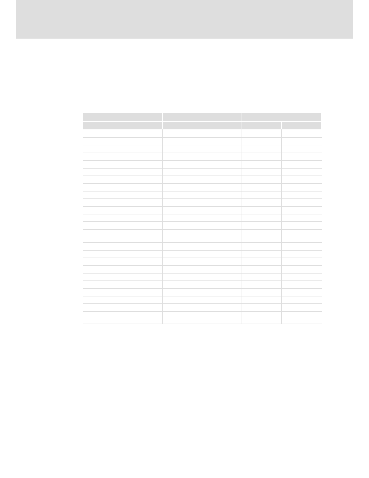
The following table shows the components of the optional versions of the Windows
R
CE
operating system.
Component Description Version
Core ProPlus
Web Server X X
Remote Desktop (VNC) X X
FTP Server X X
RAS Server − X
Telnet X X
Active Sync File Transfer X X
Internet Explorer 6.0 − X
Registry Editor X X
Word Pad − X
Mouse Pointer X X
USB Keyboard Driver X X
HP Printer Driver (PCL) X X
HMI Start Manager X X
File Viewer Excel/Image/PDF/PowerPoint/Word
Viewer
− X
.NET Compact Framework 2.0 X X
USB Support X X
Touch Driver X X
TCP/IP X X
CAN Driver, Control Panel Applet X X
MPI Driver, Control Panel Applet X X
Soft Keyboard Software Input Panel X X
Control Panels X X
Network Tools Ping, Tracert, Netstat, Net X X
Visual Studio Communication
Components
ConmanClient2, Clientshutdown X X
Page 40
Operation
Control Panel Applets
8
40
LDCDS−EL100 EN 8.0
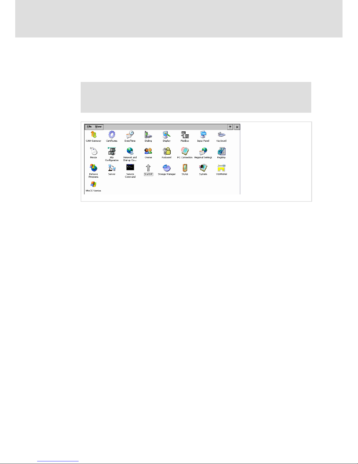
8.2 Control Panel Applets
The Control Panel Applets adjusted or advanced by LENZE are described in the following.
Note!
A description of the standard WindowsR CE applets can be found in the
Windows
R
CE literature.
EL100−022
How to open the Control Panel:
1. Click Start ® Settings ® Control Panel on your EL 1xx.
The Control Panel window will be opened.
Page 41
Operation
Control Panel Applets
StartUp
8
41
LDCDS−EL100 EN 8.0
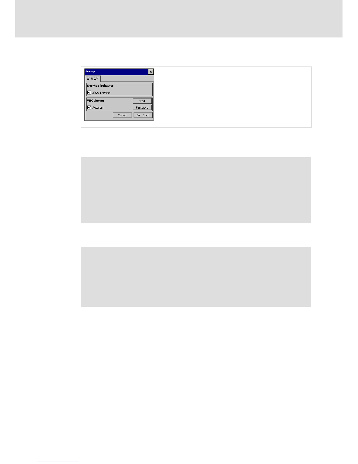
8.2.1 StartUp
EL100−023
Show Explorer: After the booting, the Windows CE desktop (Explorer) will be started if this
control field has been selected. Programs and settings cannot be accessed if this control
field has not been selected.
Note!
A disabled desktop can only be re−enabled via USB keyboard:
ƒ Press Shift + F4 on the keyboard. The Control Panel will be opened.
ƒ Open StartUP dialogue.
ƒ Select Show Explorer control field.
ƒ Click OK.
ƒ Restart the EL 1xx. The desktop will be re−enabled after a restart.
VNC Server Autostart: After the booting, the VNC Server will be started automatically if
this control field has been selected.
Note!
The VNC Server is not protected by a factory−set password. If the connection is
not required, the server should be disabled to prevent unauthorised access.
Alternatively, establish a password−protected connection.
An active VNC connection means additional load for the system. Hence, we
recommend to start the VNC Server manually via your Web Server if need be
instead of selecting the "Autostart" control field ( 67).
Start: Start VNC Server manually.
Password: Assign password for a password−protected connection (max. 15 characters).
Page 42
Operation
Control Panel Applets
Registry
8
42
LDCDS−EL100 EN 8.0
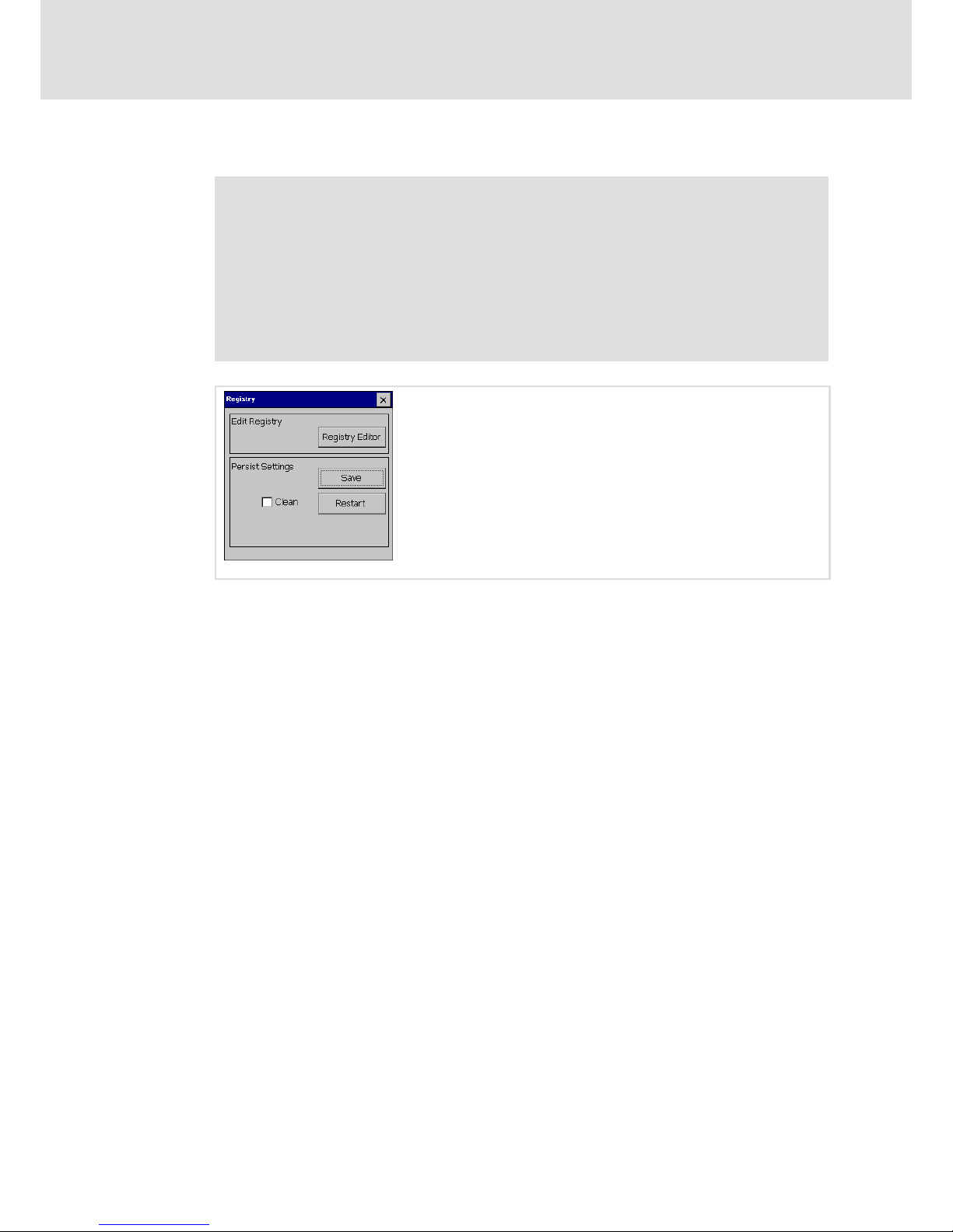
8.2.2 Registry
Note!
The modifications of some Applets are automatically stored in the Registry
when you click OK (message "Saving").
The modifications of other Applets are not stored automatically in the
Registry, which means that they are lost after a restart. If you wish to make
permanent modifications to these Applets, proceed as follows:
ƒ Click Start ® Settings ® Control Panel ® Registry on your EL1xx.
ƒ Click Save.
EL100−024
Registry Editor: Opens the Registry Editor.
Save: Saves the Registry.
Restart Device: Restarts the EL 1xx.
Clean: After a restart, the Registry is reset to the default setting if this control field has been
selected.
Page 43
Operation
Control Panel Applets
VisiWinNET
â
8
43
LDCDS−EL100 EN 8.0
8.2.3 VisiWinNET
â
EL100−025
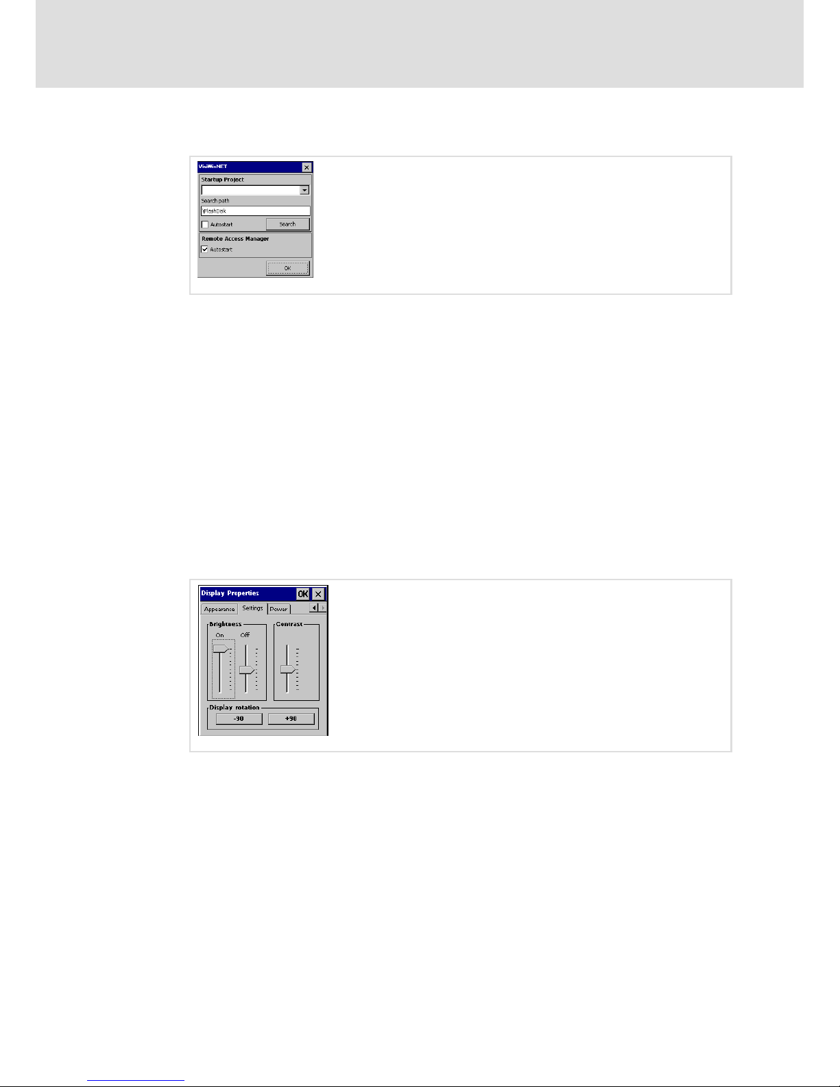
Startup Project: Display of the VisiWinNETâ start project entered in the registry. The EL 1xx
can be searched for installed projects via the Search button. (Note: The search function is
only able to find those projects whose file extension (".vwn") exclusively consists of lower
case letters.)
Search Path: Path that is searched for VisiWinNET
â
projects. The search process can be
accelerated via this preselection if the data carrier is very large or full.
Autostart: Startup Project will be started automatically when the system is started.
Search: VisiWinNET
â
project search.
Remote Access Manager "Autostart": When the system is started, the VisiWinNET
â
Connection Manager will be started automatically if this control field has been selected.
OK: The settings are saved. The registration is stored.
8.2.4 Display
EL100−026
Brightness: Changing the brightness of the display. (For EL 105m without function.)
Contrast: Changing the contrast of the EL 105m display. (For all other devices without
function.)
Display rotation: The "−90" and "+90" buttons can be used to rotate the EL 1xx screen in
90−degree steps.
Page 44
Operation
Control Panel Applets
Server
8
44
LDCDS−EL100 EN 8.0
8.2.5 Server
EL100−027
Find more information later in this chapter ( 63).
8.2.6 Fieldbus
EL100−028
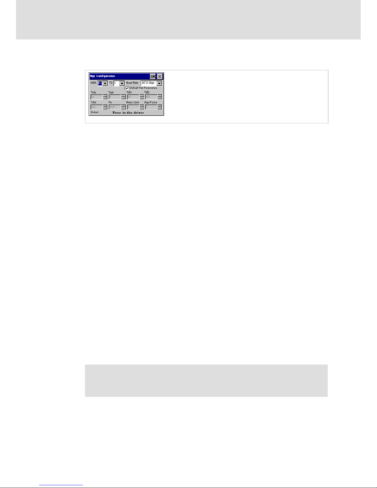
This Applet is only relevant for an EL1xx CAN. It has no function in an EL1xx MPI.
EL1xx CAN Device Node: EL1xx node address within a CAN fieldbus network.
Baud Rate: Transmission speed of the fieldbus. The baud rate must be identical for each
fieldbus node within the same network. The fieldbus parameters are set according to the
baud rate.
Page 45
Operation
Control Panel Applets
MPI Configuration
8
45
LDCDS−EL100 EN 8.0
8.2.7 MPI Configuration
EL100−029
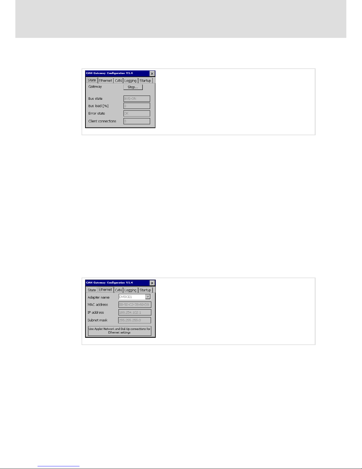
This Applet is only relevant for an EL 1xx MPI.
HSA: Set the highest MPI address (Highest Station Address) here. The highest MPI address
must be identical within an MPI network!
TS (This Station): Set the local MPI address for the EL 1xx here.
Baud Rate: Transmission speed of the MPI network. The baud rate must be identical for
each MPI node within the same network. The MPI parameters are set according to the baud
rate.
Default Net Parameters: Default Net Parameters specified due to the baud rate. We
recommend not to modify them.
Status: The status of the MPI interface is displayed as "Offline", "Online" or "Error" in the
status bar.
See VisiWinNET
â
Smart software manual for further information.
8.2.8 CAN Gateway
The CAN gateway function is used to implement data transmission from an Ethernet
network to the Lenze "CAN system bus" fieldbus. The following functions are supported:
ƒ Data transmission via SDO
ƒ Parameter data exchange
ƒ Program download from PC to Lenze drive components
Communication between the PC and the Lenze drive components connected to the CAN
system bus is possible via the following programs:
ƒ DriveServer, Global Drive Control, Global Drive Loader
ƒ Global Drive PLC Developer−Studio
ƒ L−force Engineer
Note!
The CAN gateway function is only supported if CAN communication software
from version 2.2.2.0 is installed on the PC.
Further information is provided elsewhere in this manual ( 69).
Page 46
Operation
Control Panel Applets
CAN Gateway
8
46
LDCDS−EL100 EN 8.0
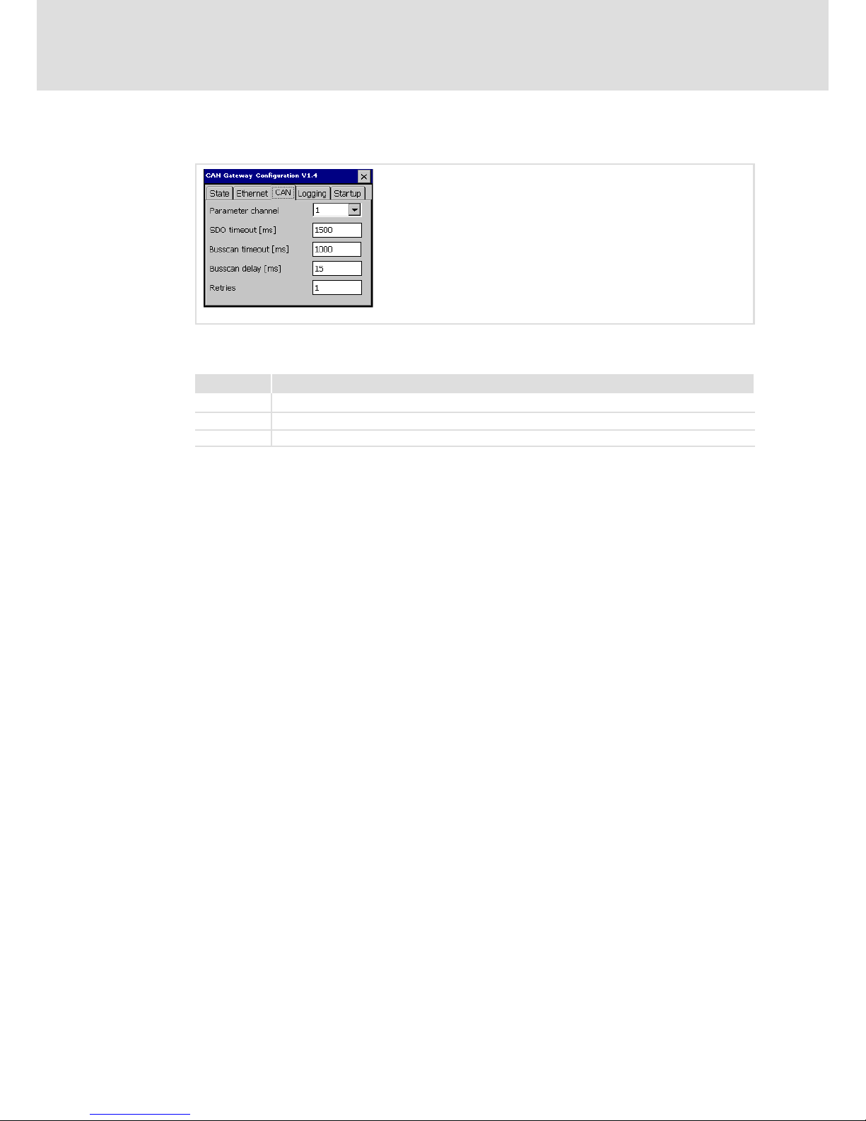
"State" register
EL100−032
Gateway: Start and stop gateway function
Bus state: Current state of the CAN system bus (BUS−ON or BUS−OFF)
Bus load (%): Current bus load
Error state: Current error
Client connections: Number of connected Ethernet nodes
Status message interpretation (bus state and error state):
BUS−ON and OK: CAN communication is alright.
BUS−ON and ERROR: The warning limit of the CAN controller has been reached or exceeded
(too many error frames). CAN communication is still possible.
BUS−OFF and ERROR: The CAN controller has reached the BUS−OFF state. CAN
communication is not possible. A reset of the device is required.
"Ethernet" register
EL100−033
Adapter name: Select the adapter here whose settings are to be displayed.
MAC address, IP address, Subnet mask: Settings from the "Network and Dial−up
Connections for Ethernet" applet.
Page 47
Operation
Control Panel Applets
CAN Gateway
8
47
LDCDS−EL100 EN 8.0
"CAN" register
EL100−034
Parameter channel: The parameter channel for data transmission is selected here if the
drive component has more than one parameter channel.
Selection Selectable address range
0 1 ... 127 (parameter channel 1 acc. to CANopen)
1 1 ... 63 (parameter channel 1 acc. to Lenze system bus (CAN))
2 64 ... 127 (parameter channel 2 acc. to Lenze system bus (CAN))
The address of e.g. parameter data channel 2 can be calculated as follows:
Address of parameter data channel 2 = Address of parameter data channel 1 + offset 64.
By selecting a value of "0", the bus is "CanOpen" compliant. There is no restriction to the
address range.
SDO timeout [ms]: The time set here defines the time slot a CAN node has to respond to
a request. If there is no response within the set time, the requesting component will
assume that the node is unavailable.
Busscan timeout [ms]: During a bus scan, the system is waiting for the nodes to respond.
On the one hand, the busscan timeout must be large enough to provide all nodes with
sufficient time to respond. On the other hand, the search will be slowing down if the
busscan timeout is too large.
Busscan delay [ms]: Under a heavy CAN bus load, searching the CAN bus for connected
nodes may cause faults. A delay time between the transmission messages can be set to
avoid this situation, thereby causing the search to take more time to finish.
Page 48
Operation
Control Panel Applets
CAN Gateway
8
48
LDCDS−EL100 EN 8.0
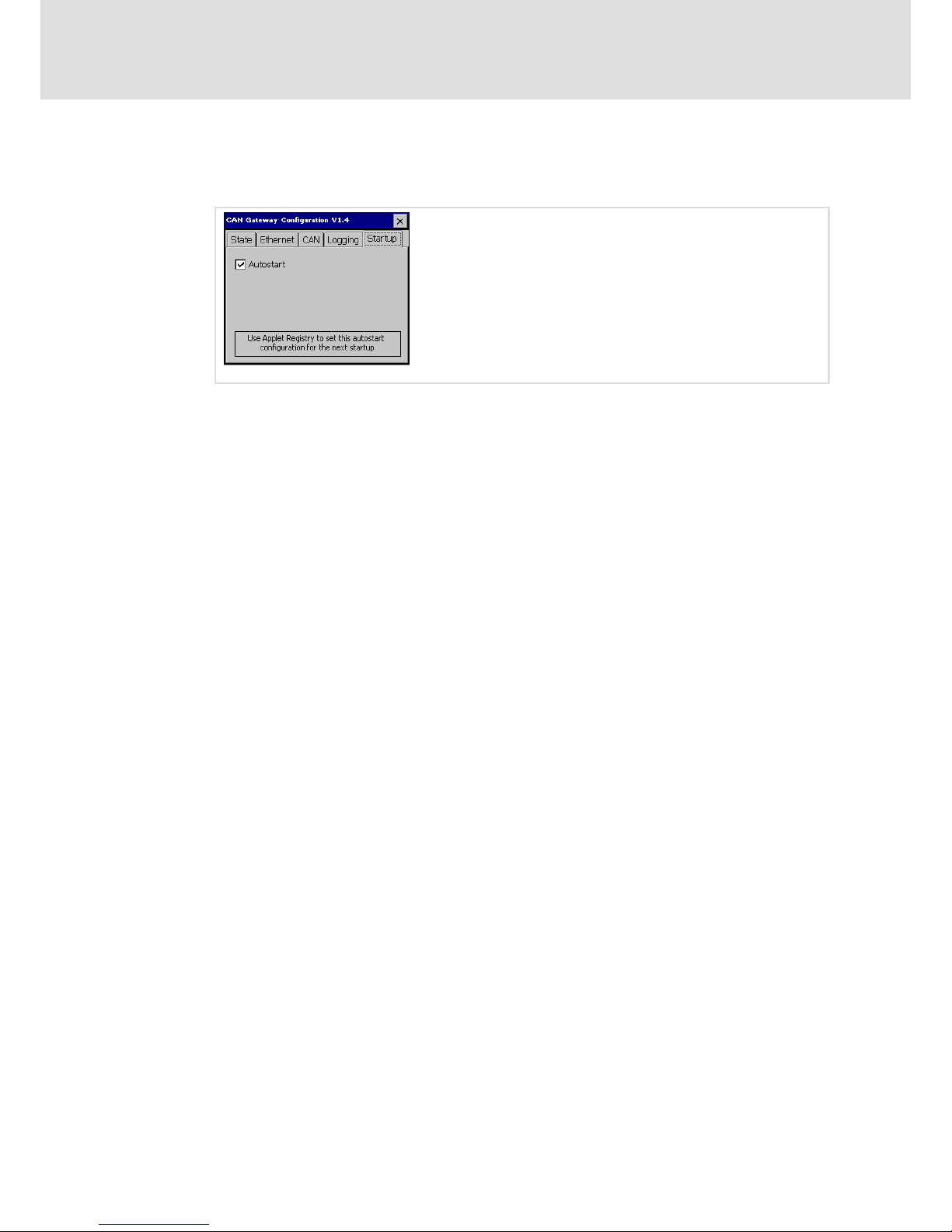
"Logging" register
This register displays errors that may be pending.
EL100−050
Autostart: If this option is selected, the CAN gateway is automatically activated when the
device is started. Alternatively, the CAN gateway must be activated manually on the
"State" register.
Page 49

Operation
Creating a PLC sample program
General information on PLC programming
8
49
LDCDS−EL100 EN 8.0
8.3 Creating a PLC sample program
The following description is only valid for types with integrated PLC (EL 1xx PLC).
In the following sections you will find a description of the basics for creating a PLC program
using the Lenze PLC Designer. For more information about the PLC Designer, please see the
online help for the PLC Designer.
The example describes how to program a simple counter, how to create a .sym file and how
to transfer the program to the PLC of the EL 100 PLC.
To follow the steps described in the following sections, the "PLC Designer" software must
have been installed on your system.
8.3.1 General information on PLC programming
Please observe the following when configuring your EL 1xx:
ƒ The variable type LREAL does not exist.
ƒ For direct addresses (%I / Q / M), a natural alignment must be used; i.e.
– BYTEs to any addresses
– 16−bit values (WORD, INT) to even addresses
– 32−bit values (DWORD, DINT) to addresses divisible by 4
ƒ Avoid floating−point operations because they will be emulated and therefore take
much longer than on an X86 with FPU.
ƒ Avoid task runtimes < 100 ms because short task runtimes have disadvantages
regarding visualisation (long reversing times).
Page 50
Operation
Creating a PLC sample program
Start PLC Designer
8
50
LDCDS−EL100 EN 8.0
8.3.2 Start PLC Designer
How to proceed:
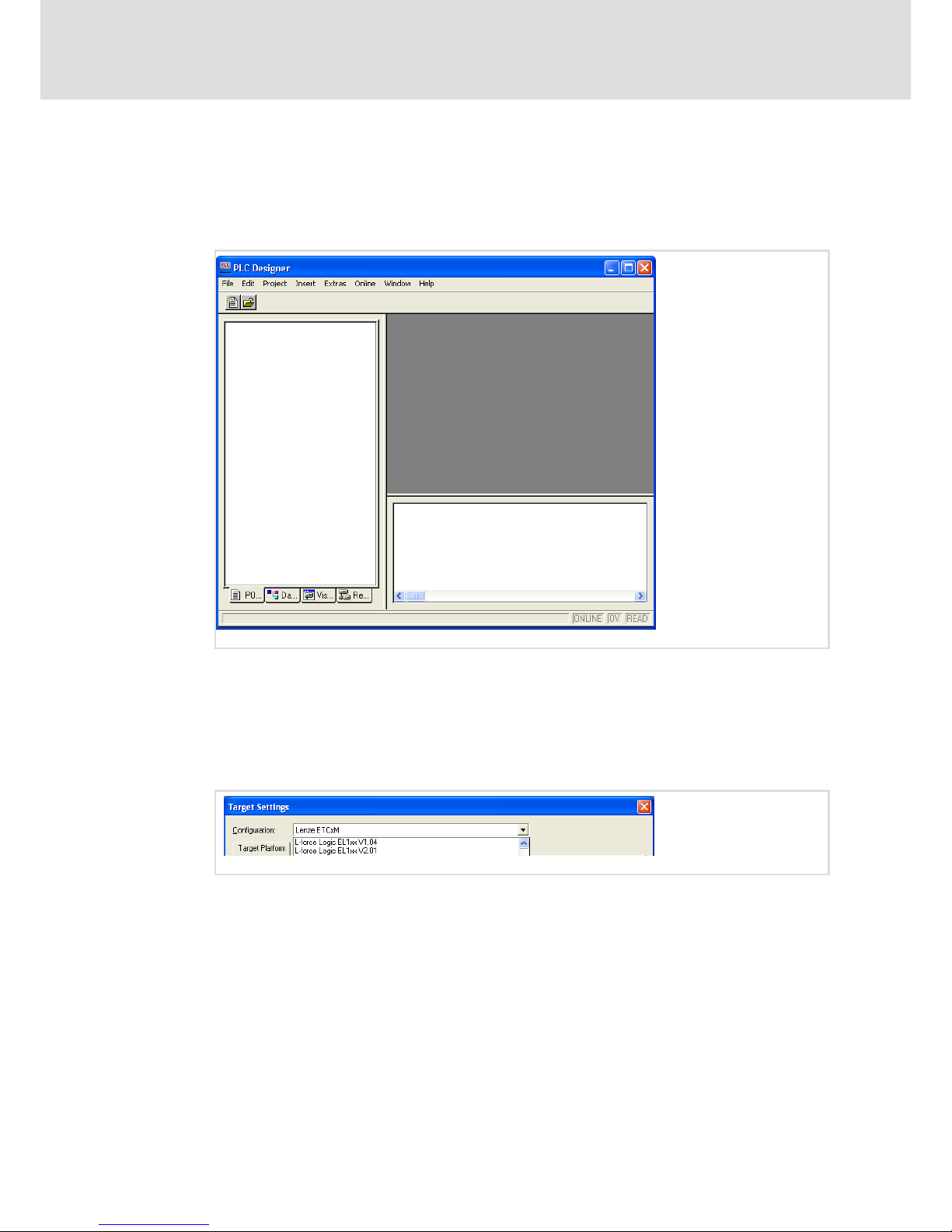
1. With a standard installation, the PLC Designer is started via Start Lenze PLC
Designer Vx.x.x.x PLC Designer.
8.3.3 Create PLC program
How to proceed:
1. Open the menu File in the PLC Designer menu bar and select the menu item New.
The "Target Settings" dialogue will be opened.
2. Select the target system depending on the HMI used from the Configuration
selection list:
EL 1xx: L−force Logic EL1xx v1.09
EL 1xx ECO: L−force Logic EL1xx v2.06
If the target system is not available in the Configuration selection list, you can
download it from the download area of the Lenze homepage (www.lenze.com).
3. Click OK to close the dialogue.
The "Target settings" dialogue will be expanded.
Page 51
Operation
Creating a PLC sample program
Create PLC program
8
51
LDCDS−EL100 EN 8.0
4. Enable the General register and select the Download symbol file control field.
This enables data exchange between the visualistion and the PLC.
5. Click OK to close the dialogue.
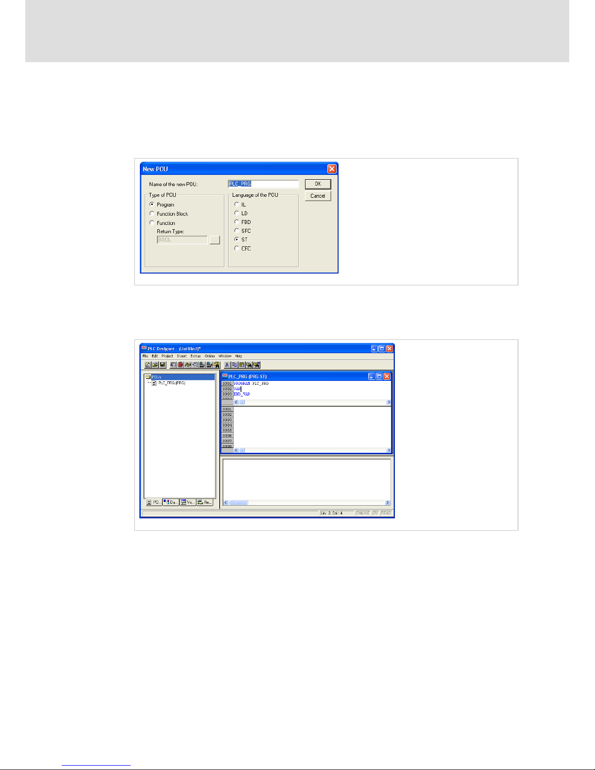
The "New POU" dialogue will be opened.
6. Select the ST (structured text) control field.
7. Click OK to close the dialogue.
The "PLC_PRG (PRG−ST)" programming window will be opened.
In the next step, we will declare a local variable.
Page 52
Operation
Creating a PLC sample program
Create PLC program
8
52
LDCDS−EL100 EN 8.0
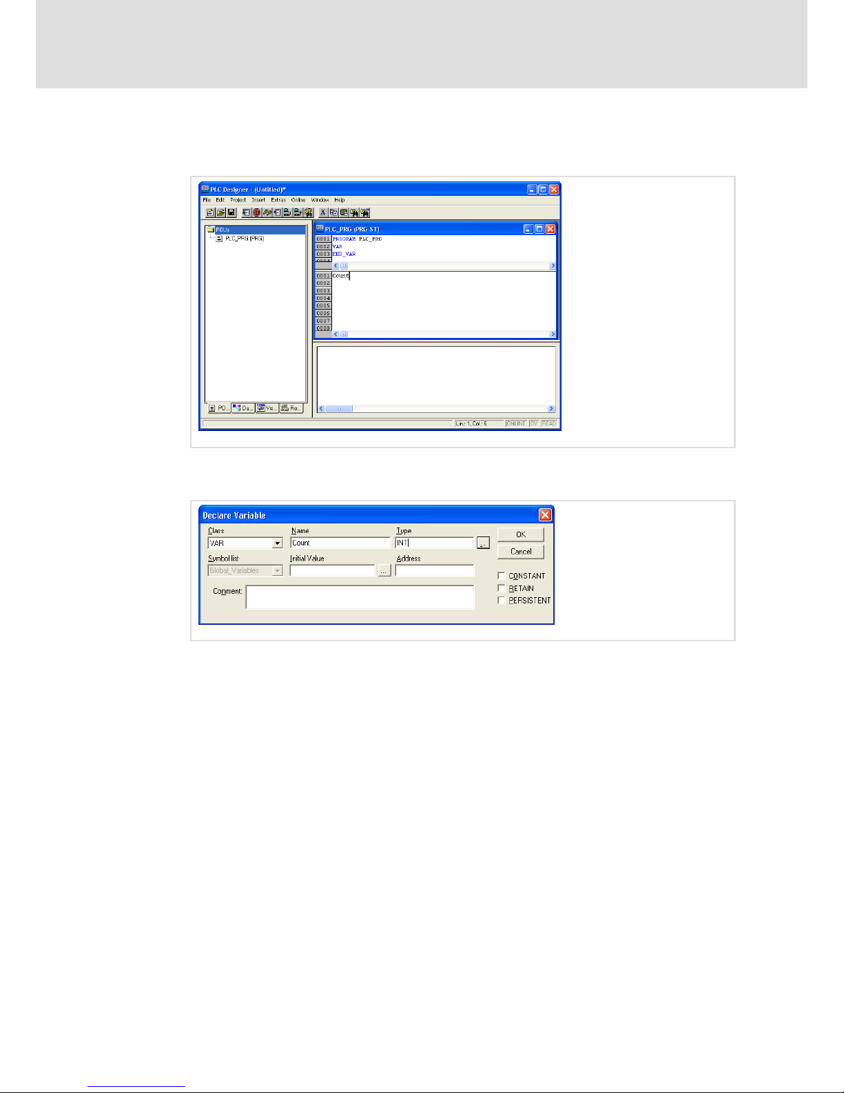
8. Enter the word "Count" in the lower half of the divided "PLC_PRG (PRG−ST)"
programming window.
9. Press [Enter]
The "Declare Variable" dialogue will be opened.
10. Use [...] to the select the variable type "INT".
11. Click OK to close the dialogue.
After this, we will enter the code for a simple counter in our example program.
Page 53

Operation
Creating a PLC sample program
Create sym file
8
53
LDCDS−EL100 EN 8.0
12. Enter the following code in the lower half of the divided "PLC_PRG (PRG−ST)"
programming window: Count:=Count+1
Our PLC program is now complete and can be saved.
13. Go to the menu bar, open the menu File and select the menu item Save as.
14. Enter an optional program name (e.g. "example project") in the "Save as" dialogue,
select a memory location and click Save.
After this, we will transfer the program to the HMI. Before doing so, a sym file must be
created.
8.3.4 Create sym file
A sym file is required if the visualisation, e.g. VisiWinNet
â
Smart is to access the PLC
program. A sym file contains all variables and declarations of the PLC program.
How to proceed:
1. Open the menu Project in the PLC Designer and select the menu item Options.
The "Options" dialogue will be opened.
2. Select the "Symbol configuration" category from the "Options" dialogue.
Page 54

Operation
Creating a PLC sample program
Create sym file
8
54
LDCDS−EL100 EN 8.0
3. Select the Dump symbol entries control field and click the Configure symbol file
button.
The "Set object attributes" dialogue will be opened.
4. Select the Export variables of object control field in the "Set object attributes"
dialogue. Do not change the other control field selections.
5. Go to the object tree and select all objects which contain variables for the
visualisation and are enabled via the variables of the object.
Only export those variables required for visualisation. The smaller the sym file the
shorter the baud rate to the target system.
6. Close the "Set object attributes" dialogue and the "Options" dialogue with OK.
7. Go to the menu bar, open the menu Project and select the menu item Clean all.
8. Open the menu Project once again and select the menu item Rebuild all.
The project is checked, compiled and saved under the file name "ExampleProject.sym"
at the selected memory location.
Note!
If the Download symbol file control field is checked when the variable is
created ( 51), the sym file will be transferred automatically when the project
is downloaded to the EL 100.
If you create new variables for the visualisation in the PLC program, a new sym
file must be created.
Page 55
Operation
Creating a PLC sample program
Transfer program to HMI
8
55
LDCDS−EL100 EN 8.0
8.3.5 Transfer program to HMI
How to proceed:
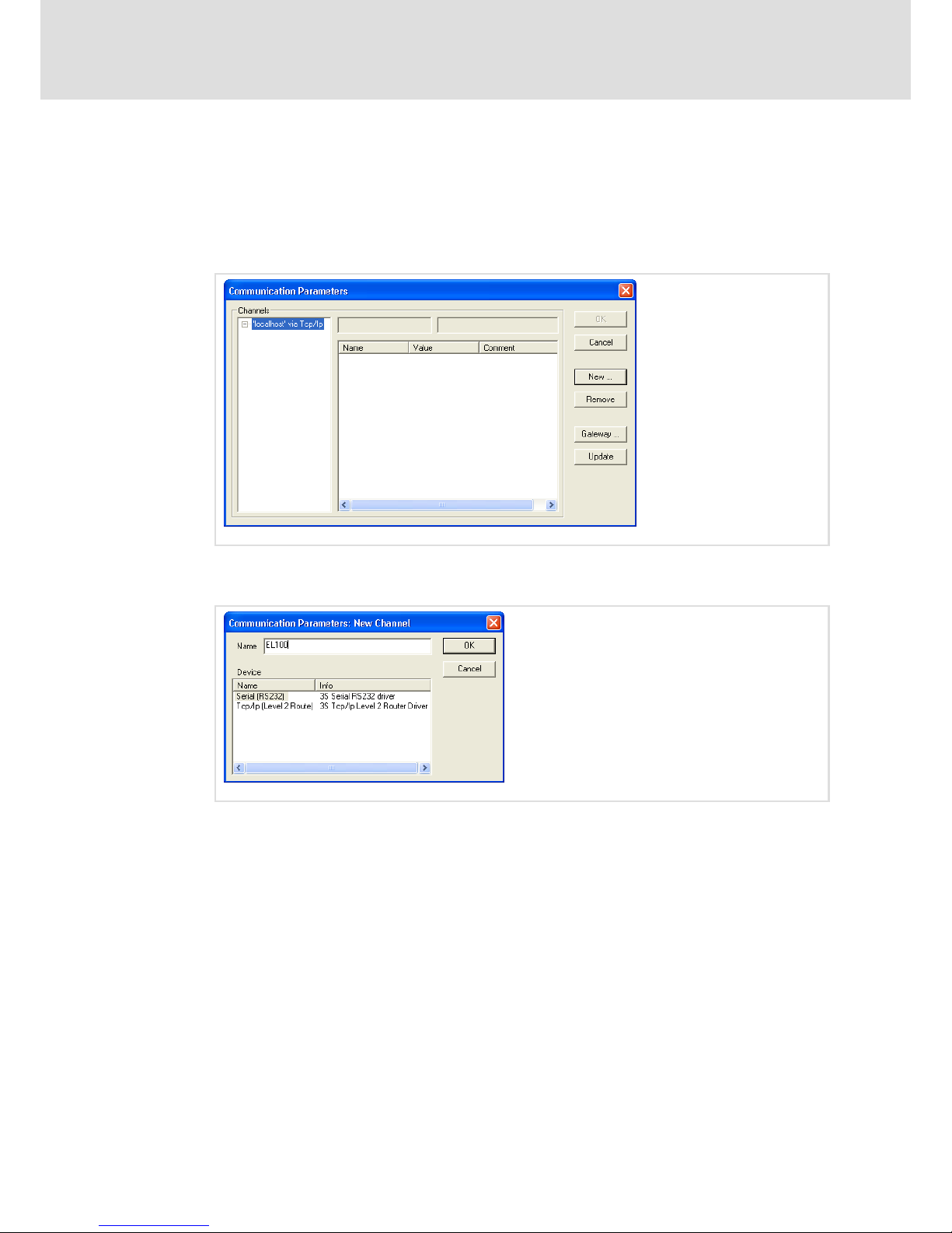
1. Go to the menu bar, open the menu Online and select the menu item
Communication Parameters.
The "Communication Parameters" dialogue will be opened.
2. Click the New button.
The "Communication Parameters: New Channel" dialogue will be opened.
3. Enter a name for the new communication channel (e.g. EL100) and select the entry
"Tcp/lp (Level 2 Route)".
Page 56
Operation
Creating a PLC sample program
Transfer program to HMI
8
56
LDCDS−EL100 EN 8.0
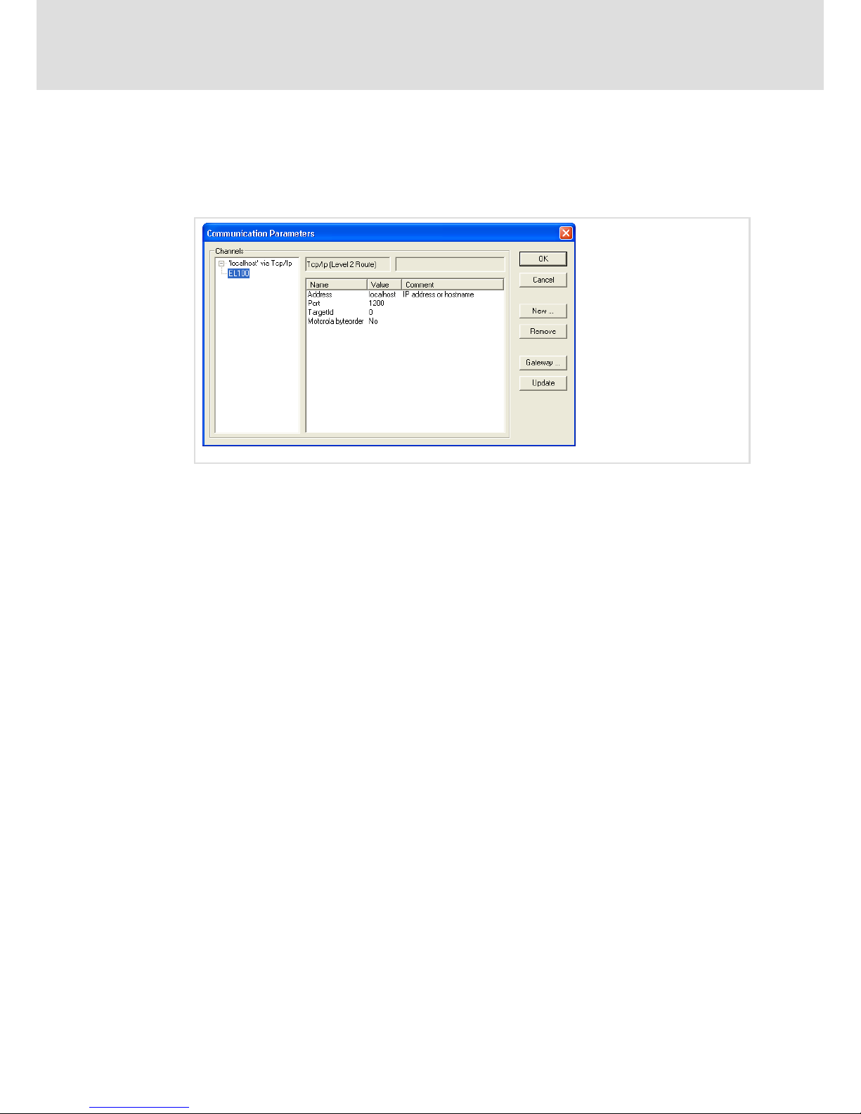
4. Click OK to close the dialogue.
After this, the "Communication Parameters" dialogue will be active again. The name
of the new channel is indicated in the left dialogue field. If you select the entry, the
corresponding data will be indicated in the right dialogue field.
5. Click the field with the entry "localhost" ("Address" line, "Value" column) and enter
the IP address of the HMI.
The HMI IP address will be displayed if you double−click the network symbol in the
status bar of your EL1xx.
Since the HMI does not include a Motorola processor, the entry "Motorola byteorder =
No" must be indicated.
6. Click OK to close the dialogue.
Communication between PLC Designer and HMI has now been configured. In the next
step, we will establish the connection to the HMI.
7. Go to the menu bar, open the menu Online and select the menu item Login.
8. Confirm the question if the program is to be saved with Yes.
The project is transferred to the HMI. While the project is being transferred, a dialogue
will be displayed. After the dialogue has disappeared, you can start the program on
your HMI.
Page 57
Operation
Creating a PLC sample program
Start program on HMI
8
57
LDCDS−EL100 EN 8.0
8.3.6 Start program on HMI
How to proceed:
1. Go to the menu bar, open the menu Online and select the menu item Run.
The project is started on the HMI.
Note!
If the project is to be loaded automatically after every restart of the HMI, you
can define it as a "boot project". For this, proceed as follows:
ƒ Go to the menu bar, open the menu Online and select the menu item Create
boot project.
A dialogue will be opened which indicates the files created.
ƒ Click OK to close the dialogue.
If you want to use the project again later, save the project.
2. For this, go to the menu bar, open the menu File and select the menu item Save.
8.3.7 Build up CAN communication with distributed I/O module
How to proceed:
1. Open the project from which you want to access the I/O module.
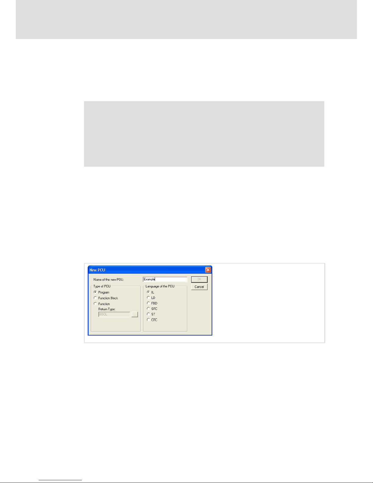
2. Go to the Project Explorer, enable the POUs registry, click the right mouse button
and select the menu item Add Object from the context menu to create a new object.
The "New POU" dialogue will be opened.
3. Enter the name for the object and select the IL control field.
4. Click OK to close the dialogue.
5. For creating a new task, change to the Resources registry in the Project Explorer.
6. Double−click the entry Task configuration.
The "Task configuration" window will be opened.
Page 58
Operation
Creating a PLC sample program
Build up CAN communication with distributed I/O module
8
58
LDCDS−EL100 EN 8.0
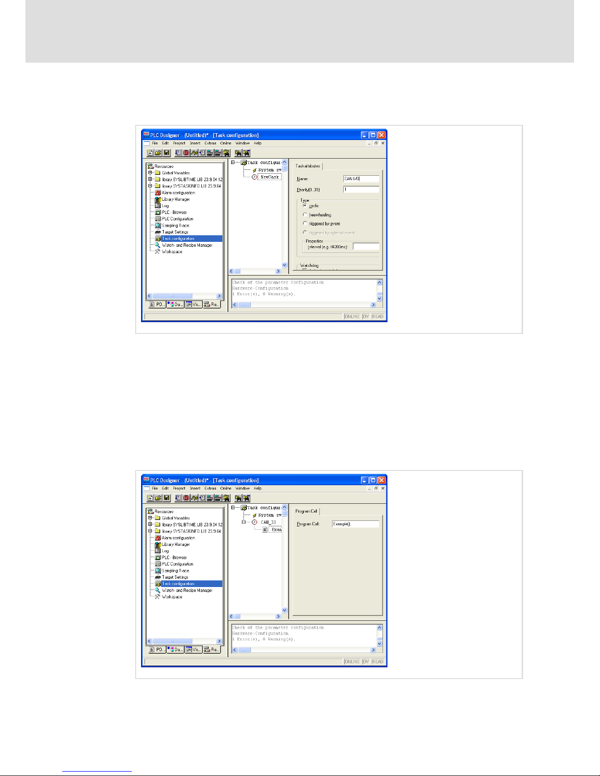
7. Right−click the Explorer area of the window and select Insert Task from the context
menu.
8. Configure your task:
– Name: Optional name
– Priority: 1 (highest priority)
– Type: Cyclic
– Properties/Interval: T#100 ms
After this, a program call must be added to the task. The program will then be called
cyclically every 100 ms.
9. For this, right−click the new task in the Explorer area of the "Task configuration"
window and select Append Program Call from the context menu.
Page 59
Operation
Creating a PLC sample program
Build up CAN communication with distributed I/O module
8
59
LDCDS−EL100 EN 8.0
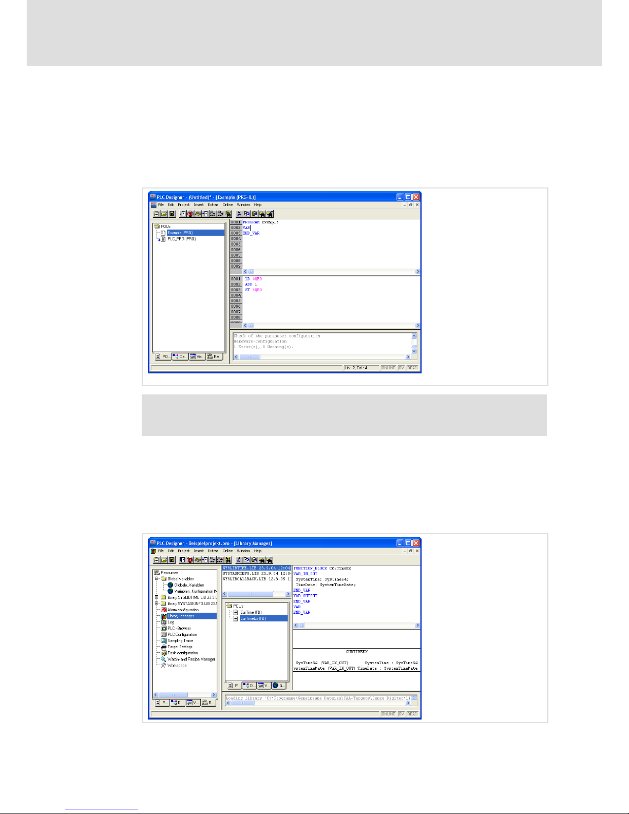
10. Click the ... button and select the object which you have created in step 2 in the
following dialogue.
11. Close the dialogue with OK and change to the POUs registry in the Project Explorer.
12. Go to the POUs registry and write your program.
The following example program has the function of a simple counter: the value of the
I/O module byte "QB0" is incremented.
Note!
Leave an instruction in the main program, otherwise, compile errors will occur.
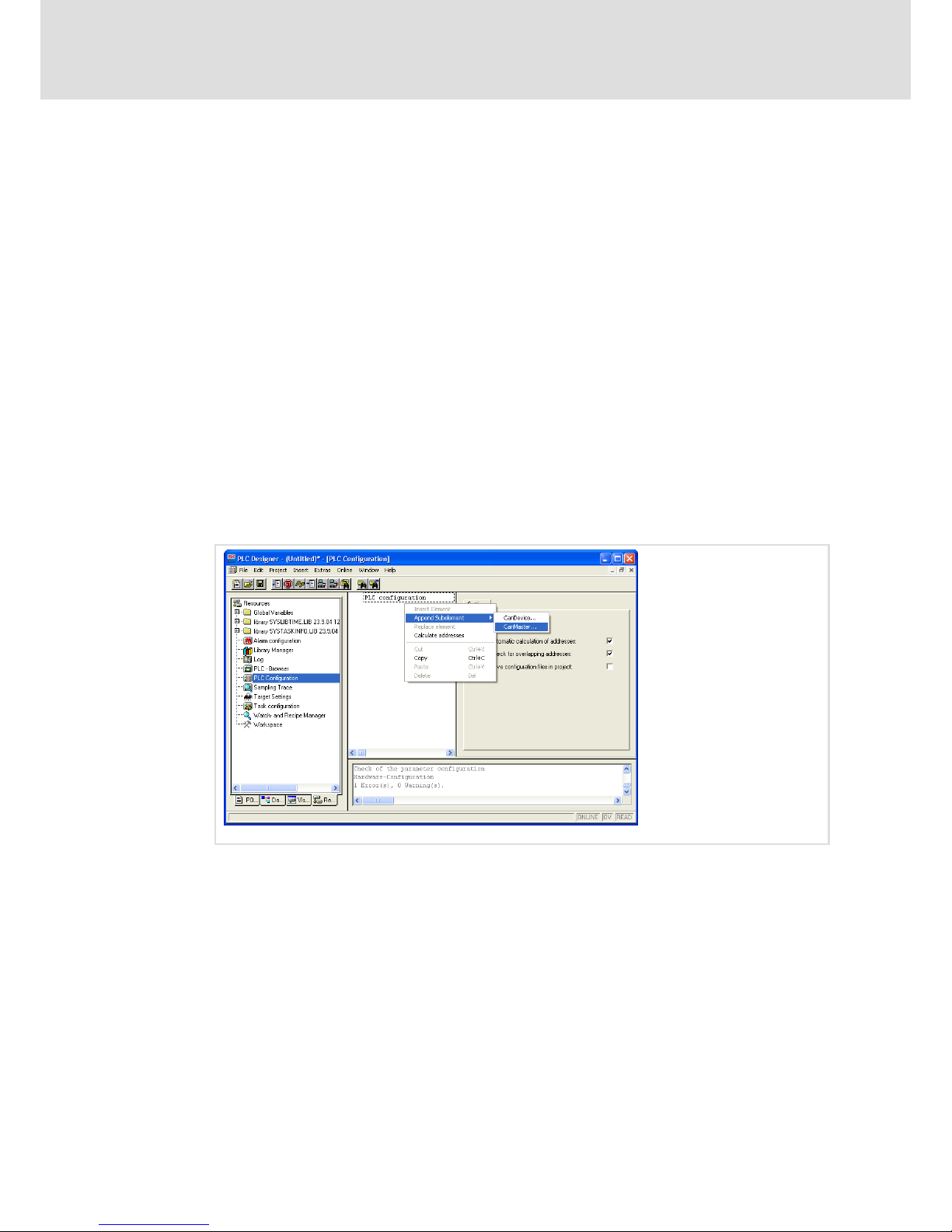
For establishing a CAN connection with the I/O module, some libraries must have been
loaded.
13. For this, go to the Resources registry in the Project Explorer and double−click the
entry Library Manager.
The "Library Manager" window will be opened. The libraries which have been loaded
will be displayed in the upper area on the left.
Page 60
Operation
Creating a PLC sample program
Build up CAN communication with distributed I/O module
8
60
LDCDS−EL100 EN 8.0
14. Right−click the upper, left window pane and select Additional Library from the
context menu to load the libraries.
Load the following libraries one after the other:
– 3S_CanDrv.lib
– 3S_CANopenManager.lib
– 3S_CANopenMaster.lib
For adding a module to the network, its device−specific configuration file must be
added to the project. The settings possible for a CAN module are described in an EDS
file. The EDS files can be found under http://www.lenze.de
15. Go to the Resources registry in the Project Explorer and double−click the entry PLC
Configuration to add the configuration file to your project.
The "PLC Configuration" window will be opened.
16. Click the menu item Extras Add configuration file and select the EDS file for your
CAN module in the following dialogue.
In the next step, we will add a subelement to the PLC configuration; in our example,
"CanMaster" is the PLC.
17. For this, right−click the Explorer area of the "PLC Configuration" window and select
Append Subelement CANMaster from the context menu.
Page 61
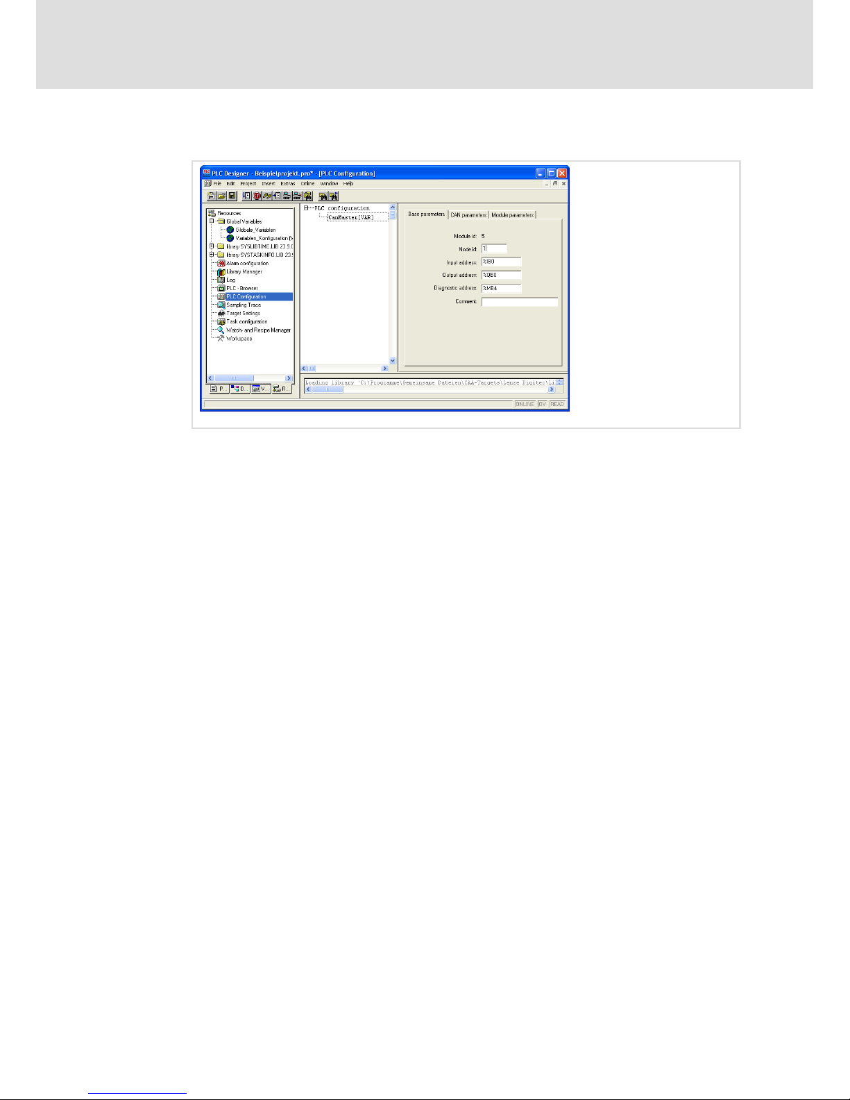
Operation
Creating a PLC sample program
Build up CAN communication with distributed I/O module
8
61
LDCDS−EL100 EN 8.0
18. Assign the node address "1" to the CanMaster.
After this, we will add a "CanDevice".
19. Go to the Explorer area and select the entry "CanMaster", click the right mouse
button and select Append Subelement CANDevice from the context menu.
20. Assign the node address selected at the I/O module to the CanDevice.
21. Change to the CAN parameters registry in the "PLC Configuration" window and enter
the "Node ID" of the I/O module.
Now, the project can be compiled and loaded into the PLC.
Page 62

Operation
Access EL 1xx via server functionality
8
62
LDCDS−EL100 EN 8.0
8.4 Access EL 1xx via server functionality
Various servers are integrated into the HMI of the EL1xx series allowing access to the
device via LAN or WLAN (internet).
ƒ FTP Server
ƒ Web Server (WebAdmin connection, SysAdmin connection)
ƒ Telnet Server
ƒ VNC Server
ƒ RAS Server (only available in the Professional Plus operating system)
Precondition for accessing a server:
ƒ The EL1xx must have a LAN / Internet connection ( 33)
ƒ If the server is accessed via a firewall, both a "Ping" and the port mentioned below
must be enabled in the firewall.
Ports used:
Application / protocol Port
CoDeSys 1200
VisiWinNet 135 / 10116
FTP 20 / 21
http 80
VNC Server 5900
Page 63
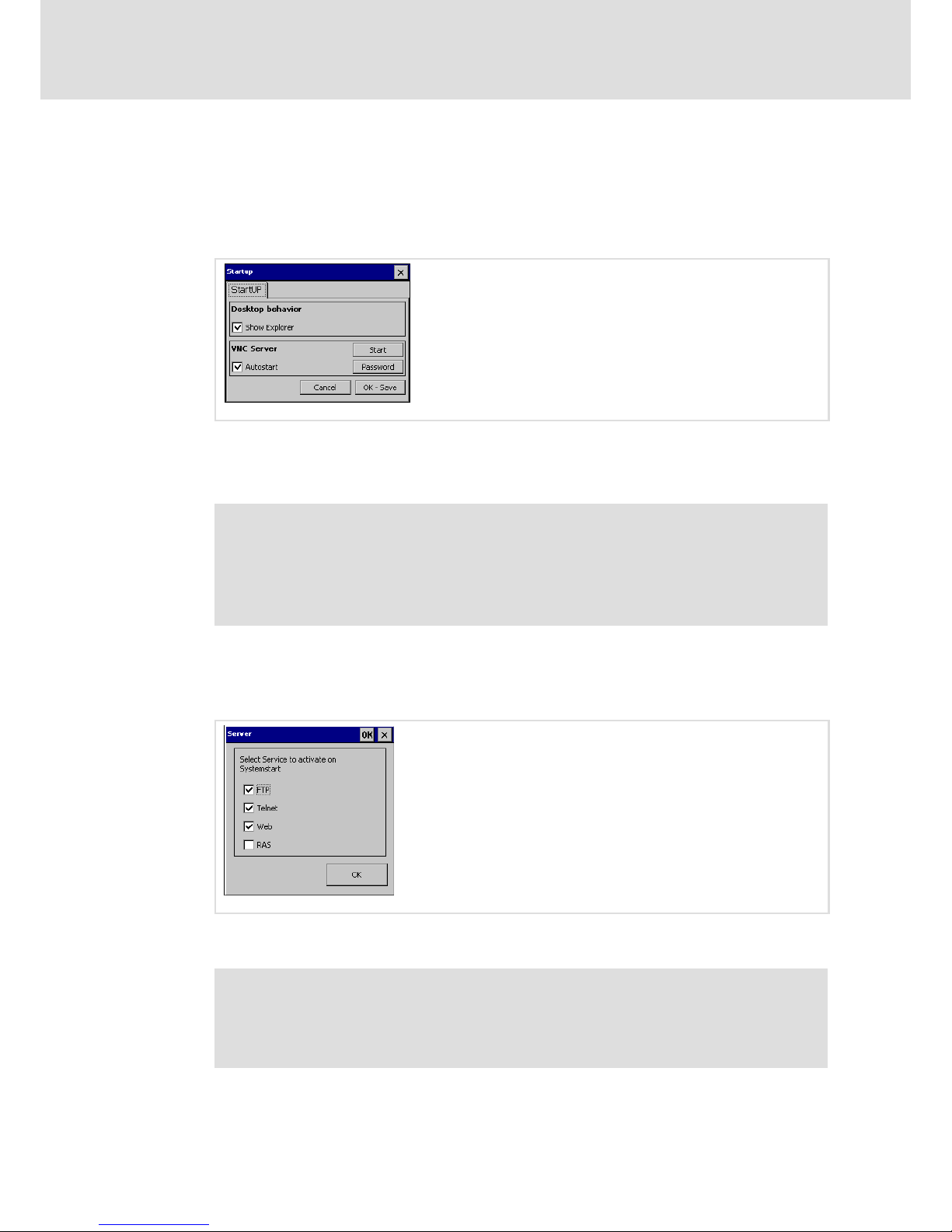
Operation
Access EL 1xx via server functionality
Enable Server Access
8
63
LDCDS−EL100 EN 8.0
8.4.1 Enable Server Access
Before the servers of the EL 1xx can be accessed via network, they must be enabled.
How to proceed with regard to the VNC Server:
1. Click Start ® Settings ® Control Panel ® Startup on your EL 1xx.
EL100−023
2. Click Start.
If the VNC Server is to be started after every restart of the EL 1xx, select the Autostart
control field.
Note!
The VNC Server is not protected by password. If the connection is not required,
the server should be disabled to prevent unauthorised access.
We recommend to start the VNC Server manually via Web Server if need be
instead of selecting the "Autostart" control field ( 67).
How to proceed with regard to other servers:
1. Click Start ® Settings ® Control Panel ® Server on your EL 1xx.
2. Select the server control fields that you wish to use.
EL100−030
If you enable the RAS Server, a dialogue box will pop up allowing you to specify
connection data.
Note!
Only enable the servers that you are actually intending to use! This will lead to
higher data integrity since it excludes the access of unauthorised computers to
your EL 1xx via that connection.
Page 64
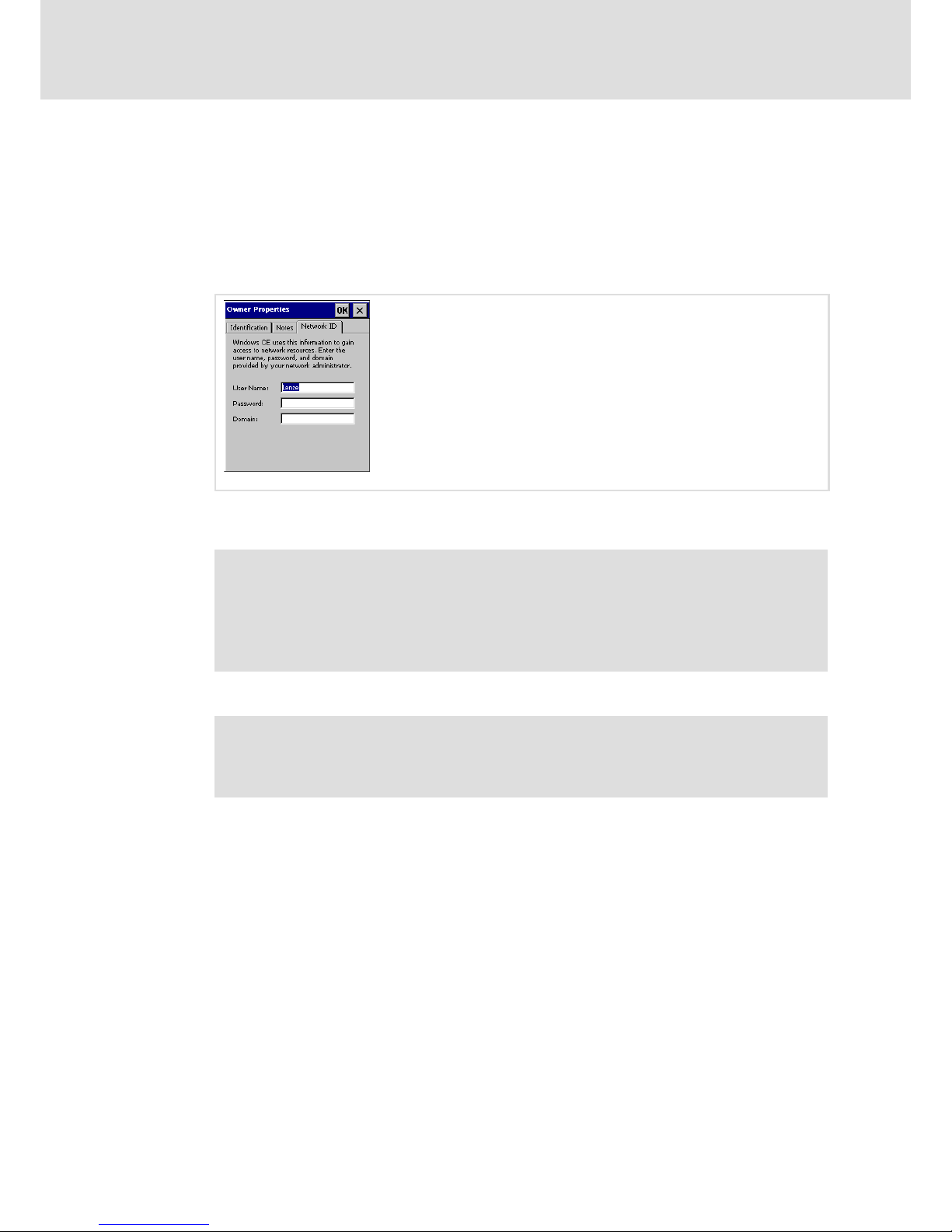
Operation
Access EL 1xx via server functionality
Enable Server Access
8
64
LDCDS−EL100 EN 8.0
Enter the password for accessing the server
The access to all servers (except for the VNC Server) is protected by a common password
which must be assigned as described in the following.
How to proceed:
1. Click Start ® Settings ® Control Panel ® Owner on your EL1xx.
2. Enable the Network_ID Registry.
EL100−031
3. Enter a User Name and a Password. If the EL1xx is connected to a network domain,
enter its name, too.
Note!
ƒ Memorise the user name and the password since this data will be queried
when logging into the server.
ƒ If you are using an unsafe password or no password at all, data integrity
cannot be guaranteed.
4. Click OK to confirm your entries.
Note!
If a password has been assigned and this dialog is opened again, the
"Password" field will be cleared. However, the password has been saved.
Page 65

Operation
Access EL 1xx via server functionality
FTP Server − Transmit Data
8
65
LDCDS−EL100 EN 8.0
8.4.2 FTP Server − Transmit Data
The access to the server via Microsoft Internet Explorer is described in the following. This
procedure and the procedures via other web browsers are similar.
Prerequisite:
ƒ The EL 1xx is switched−on and connected to the network/internet ( 33).
ƒ The access to the server has been enabled on the EL 1xx ( 63).
ƒ A user and a password have been created on the EL 1xx ( 64).
ƒ In the internet options of the PC, the "Folder View for FTP Sites" and "Use Passive
FTP (for firewall and DSL modem compatibility)" settings have been selected
How to proceed:
1. Start the Internet Explorer on your PC.
2. Enter the following address: ftp://user name@IP address
User name: ( 64)
IP address: The IP address of the EL 1xx will be displayed if you double−click on the
network symbol in the status bar of your EL 1xx.
3. Enter the User Name and the Password in the subsequent dialogue.
4. Open the menu Page in the Internet Explorer and select Open FTP Site in Windows
Explorer.
The connection will be established.
8.4.3 Web Server (SysAdmin) − Manage Processes, Files, Registry
Processes, files and Registry entries can be managed via SysAdmin connection.
Furthermore, system information is provided.
The access to the server via Microsoft Internet Explorer is described in the following. This
procedure and the procedures via other web browsers are similar.
Prerequisite:
ƒ The EL 1xx is switched on and connected to the network/internet ( 33).
ƒ The access to the server has been enabled on the EL 1xx ( 63).
ƒ A user and a password have been created on the EL 1xx ( 64).
How to proceed:
1. Start the Internet Explorer on your PC.
2. Enter the following address: http://IP Address/sysadmin
IP Address: The EL 1xx IP address will be displayed if you double−click the network
symbol in the status bar of your EL 1xx.
3. Enter the User Name and the Password in the subsequent dialogue ( 64).
4. Select No Frames or Internet Explorer 4.0 +.
The connection will be established.
Page 66

Operation
Access EL 1xx via server functionality
Telnet Server − Manage files at the Windows Command Prompt
8
66
LDCDS−EL100 EN 8.0
8.4.4 Telnet Server − Manage files at the Windows Command Prompt
The Teletype Network Server (Telnet Server) is based on a client−server protocol on TCP/IP
level. The server can be accessed via Telnet client. A Telnet client is e.g. the Windows
Command Prompt.
File or folder functions such as Create, Copy, Move To, Delete, etc. can be executed via
Telnet connection.
Prerequisite:
ƒ The EL 1xx is switched on and connected to the network/internet ( 33).
ƒ The access to the server has been enabled on the EL 1xx ( 63).
ƒ A user and a password have been created on the EL 1xx ( 64).
How to proceed:
1. Click Start ® Execute on your PC.
2. Enter the following address: Telnet IP Address
IP Address: The EL 1xx IP address will be displayed if you double−click the network
symbol in the status bar of your EL 1xx.
3. Enter the User Name in the subsequent dialogue box ( 64) and press Enter.
4. Enter the Password ( 64) and press Enter.
The connection will be established.
Enter help to obtain a list of the commands available.
Enter exit to close the connection.
Page 67

Operation
Access EL 1xx via server functionality
VNC−Server − Operate the EL 1xx by remote control via Internet or LAN
8
67
LDCDS−EL100 EN 8.0
8.4.5 VNC−Server − Operate the EL 1xx by remote control via Internet or LAN
The EL 1xx can be operated by remote control from a PC via Virtual Network Computing
(VNC). This allows you to work on a remote PC as if you were sitting in front of your EL 1xx.
Prerequisite:
ƒ The EL 1xx is switched on and connected to the network/Internet ( 33).
ƒ A VNC client is installed on the PC.
ƒ Access to the server has been enabled on the EL 1xx (Start ® Settings ® Control Panel ®
Startup)
Note!
How to proceed if you wish to enable/disable the VNC Server via Web Server:
ƒ Start the Web Server in SysAdmin mode on the PC ( 65).
ƒ Click System tools ® Processes.
ƒ Enter cevncsvr in the "Launch Process" field and click Execute to activate the
VNC server.
Click Kill beside the "cevncsvr" entry in the list of current processes to
deactivate the VNC server.
How to proceed:
1. Start the VNC client on the PC.
2. Enter the IP address of the EL 1xx.
The HMI IP address of the EL 1xx will be displayed if you double−click the network
symbol in the status bar of your EL 1xx.
If the connection is password−protected, your password will be queried.
The connection will be established.
Page 68

Operation
Access EL 1xx via server functionality
RAS Server − Operate your EL 1xx by remote control via telephone line
8
68
LDCDS−EL100 EN 8.0
8.4.6 RAS Server − Operate your EL 1xx by remote control via telephone line
This server is only available in the "Professional Plus" operating system.
Using Remote Access Service (RAS), the EL 1xx can be accessed from a PC via telephone line.
The FTP/Telnet/WEB/VNC Servers can be used for remote maintenance via RAS
connection.
Prerequisite:
ƒ The EL 1xx is connected to a modem via RS232 interface. The modem is connected to
the telephone network and switched−on.
ƒ The PC is also connected to the telephone network via modem and switched−on.
ƒ The access to the RAS Server is enabled and configured on the EL 1xx. ( 63).
ƒ A user and a password have been created on the EL 1xx ( 64).
ƒ In the modem properties dialogue box of the PC device manager, the option "Wait
For The Dial Tone Before Dialing" has been selected.
(Start Menu ®Control Panel ®System ®Device Manager®Modems)
ƒ An automatic dial−up connection has been established on the PC.
(Start Menu ® Control Panel ® Network Connections ® "Create New Network Connection"
Assistent)
How to proceed:
1. Open the automatic dial−up connection on your PC.
(Start Menu ® Control Panel ® Network Connections ® Double−click Automatic Dial−Up
Connection)
2. In the subsequent dialogue, enter the User Name, the Password ( 64)and the
Telephone Number of the connection that the EL 1xx modem has been connected
to.
3. Click Dial.
The connection will be established. A symbol for this connection is displayed in the
information area of the task bar.
4. Click the automatic dial−up connection symbol in the information area of the task
bar to verify successful dial−up.
The status of the automatic dial−up connection is displayed in a dialogue box. The IP
address of the server corresponds to the IP address of the EL 1xx.
Page 69
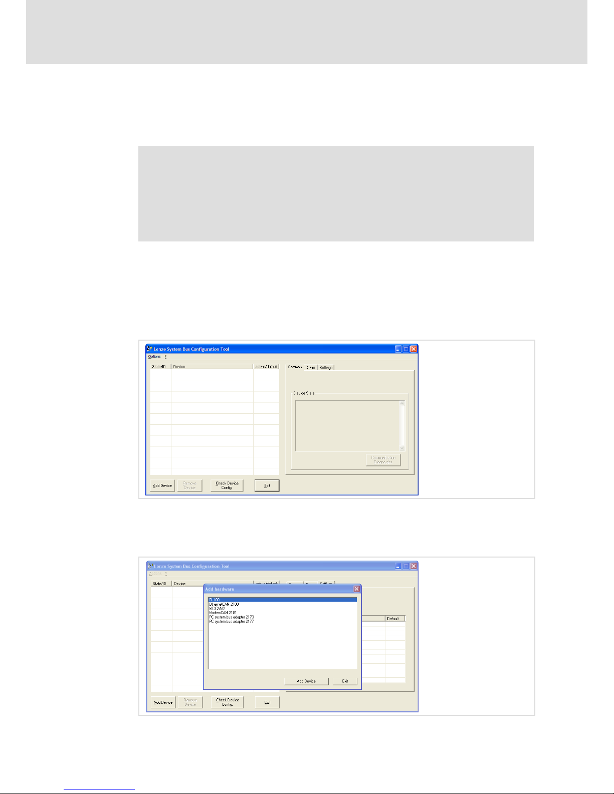
Operation
Communicating via the CAN gateway function
Important notes
8
69
LDCDS−EL100 EN 8.0
8.5 Communicating via the CAN gateway function
8.5.1 Important notes
Note!
Devices with integrated PLC (EL 1xx PLC) may have troubled communication if
the following is not observed:
Before the CAN gateway function is used
ƒ Stop PLC by a reset.
ƒ Stop corresponding visualisation.
8.5.2 Establishing communication using the system bus configurator
How to proceed:
Start the system configurator.
1. Select Start ® Programs ® Lenze ® Communication ® System Bus Configurator on your PC.
Adding and configuring a module
2. Click Add device.
The "Add hardware" dialog is displayed.
Page 70

Operation
Communicating via the CAN gateway function
Establishing communication using the system bus configurator
8
70
LDCDS−EL100 EN 8.0
3. Here, select "EL100" from the list and click Add device.
The "EL100" communication module is displayed in the system bus configurator and
can be parameterised.
4. Open the "Settings" tab to parameterise the communication between your PC and
the EL100 communication module.
EL100−037
Communication Timeout (Ethernet): Here, set a timeout which is larger than all the
timeouts in the EL100 communication module.
IP Address, Subnet Mask, Default Gateway: Adjust these settings to your network and
the communication module. If the IP address and the subnet mask have already been
assigned to the EL100, these data can be seen from the "CAN Gateway Configuration"
applet ( 45). Please also observe the following note.
MAC Address: The MAC address of the communication module serves for clear
identification of a device and is unique in the world. The MAC address is fixed in the
device and cannot be changed. The MAC address can be seen from the "CAN Gateway
Configuration" applet. ( 45). Please also observe the following note.
Note!
Alternatively, the Ethernet settings from the EL100 communication module
can also be read in online. Please ensure that the communication module is
not positioned behind routers or firewalls so that the Ethernet settings can be
read in.
Reading in Ethernet settings:
ƒ Left−click the value of the MAC address.
ƒ In the "Edit MAC address", click Search.
After a while, the "Identified communication modules" dialog is displayed.
ƒ Select the module to be used for communication.
ƒ You can either accept only the MAC address or all Ethernet settings by
clicking the corresponding button.
Page 71
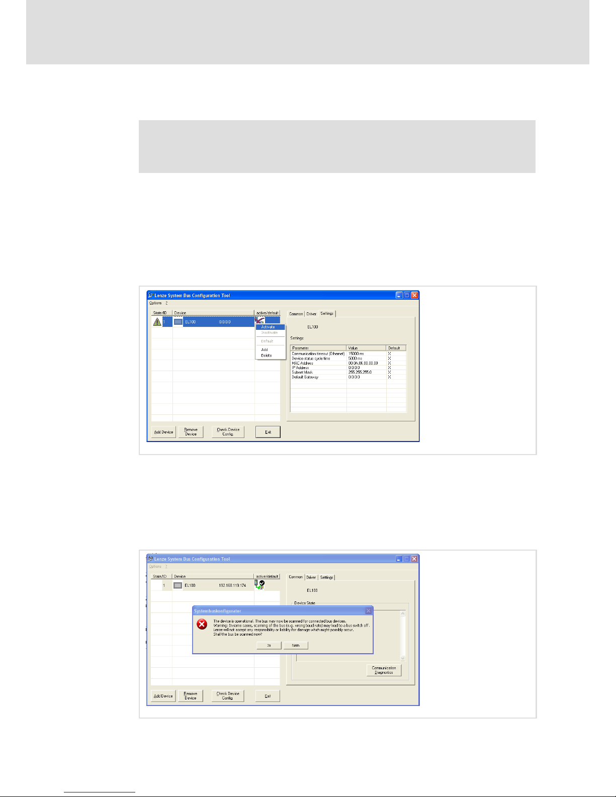
Operation
Communicating via the CAN gateway function
Establishing communication using the system bus configurator
8
71
LDCDS−EL100 EN 8.0
Activating and diagnosing communication
Note!
Communication via the Global Drive Control (GDC) or the L−force Engineer only
works if the EL1xx has been defined as the standard device.
5. Right−click the communication module and select Activate from the context menu
to activate communication.
An activated device is indicated by a red check mark in the "active/default" column.
6. Define the EL1xx communication module as the standard device by another
right−click on the communication module in the system bus configurator and
selecting Default from the context menu.
The standard device is indicated by a black check mark in the "active/default" column.
EL100−038
7. Select the new module in the system bus configurator.
8. For communication diagnostics, open the "Common" tab and click the
Communication diagnostics button.
A message is displayed. Please observe the note contained therein saying that wrong
settings may lead to a bus switch−off and that Lenze will not accept any responsibility
or liability for damage which might possibly occur.
EL100−039
Page 72
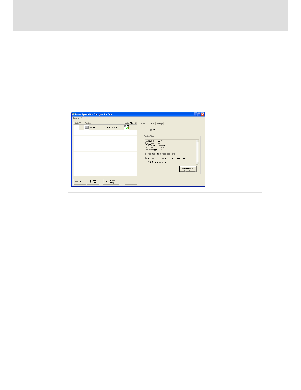
Operation
Communicating via the CAN gateway function
Establishing communication using the system bus configurator
8
72
LDCDS−EL100 EN 8.0
9. If you are positive that your communication settings are correct, confirm the
message by clicking Yes, otherwise click No.
If you have clicked "Yes", the communication module starts searching the bus for
connected devices. If the communication module was able to successfully
communicate with the connected devices, the "Device state" field will list the system
bus node addresses of the found devices.
If the communication module should not be able to communicate with the nodes, an
error message will be displayed. The communication module itself is listed with its CAN
address. However, the data telegrams regarding communication with the
communication module are not visible on the CAN bus.
EL100−040
In the case of successful configuration, the Lenze tools (e.g. GDC, Engineer, ...) are able to
communicate via the gateway function.
Page 73
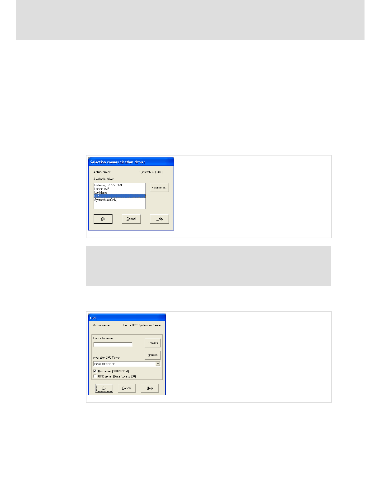
Operation
Communicating via the CAN gateway function
Establishing communication using the Global Drive Control (GDC)
8
73
LDCDS−EL100 EN 8.0
8.5.3 Establishing communication using the Global Drive Control (GDC)
The used bus system must be selected for the communication via the EL100
communication module. System bus−specific settings can be made on the EL100 module
in the "CAN Gateway" applet. The communication module can only be selected via the
system bus configurator.
How to proceed:
1. Start the Global Drive Control (GDC) program.
2. Activate the Options ® Communication menu item.
In the "Selection communication driver" dialog, a selection of communication drivers
available for the communication module is displayed.
EL100−041
Note!
We recommend to select the "OPC" communication driver in preference to the
also available "Systembus (CAN)" communication driver because the latter
causes a longer bus scan (approx. 2 min.).
3. Select "OPC" and click the Parameter... button.
The "OPC" dialog is displayed.
EL100−042
Page 74
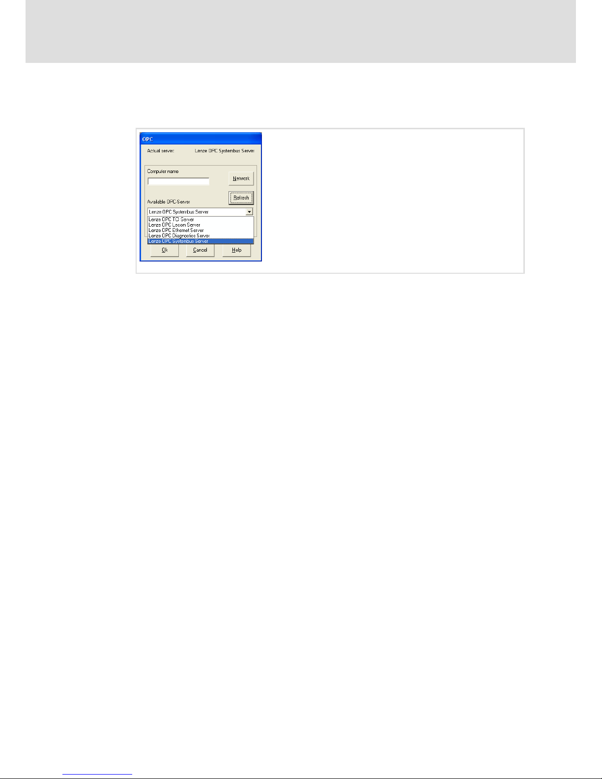
Operation
Communicating via the CAN gateway function
Establishing communication using the Global Drive Control (GDC)
8
74
LDCDS−EL100 EN 8.0
4. Click Refresh first.
The selection field displays all available OPC servers now.
EL100−043
5. Select "Lenze OPC Systembus Server" from the "Available OPC Server" selection field
and click OK.
6. Confirm your communication driver selection by clicking OK, too.
Now the GDC can be used to access the system bus via the EL100 communication module.
Page 75
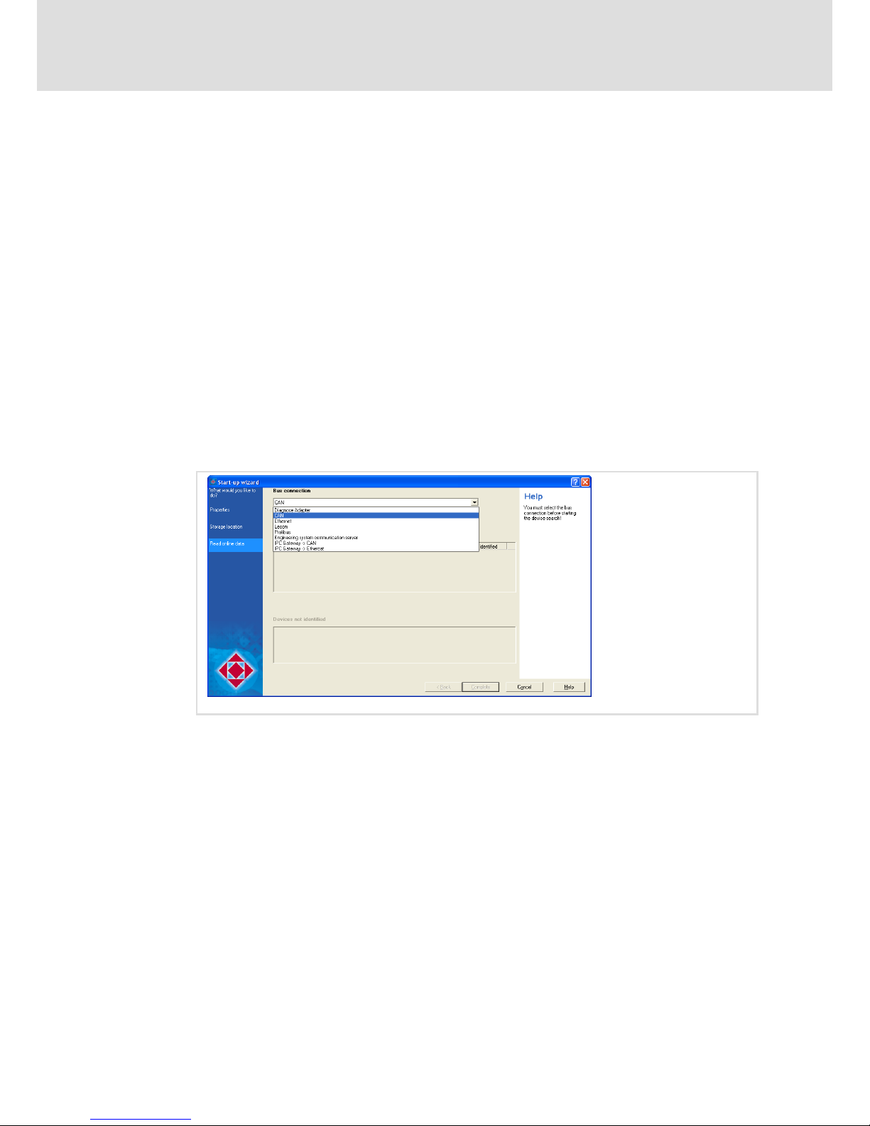
Operation
Communicating via the CAN gateway function
Establishing communication using the L−force Engineer
8
75
LDCDS−EL100 EN 8.0
8.5.4 Establishing communication using the L−force Engineer
The used bus system must be selected for the communication via the EL100
communication module. System bus−specific settings can be made on the EL100 module
in the "CAN Gateway" applet. The communication module can only be selected via the
system bus configurator.
Commissioning is illustrated by the following example. The parameter data of an 8400
frequency inverter are to be displayed using the Engineer.
How to proceed:
1. Start the L−force Engineer program and create a new program.
Information on how to proceed is provided in the L−force Engineer documentation.
2. Start the search for connected devices.
3. Define the project properties and click Next.
4. Define the storage location of the project and click Next.
5. To be able to access the 8400 frequency inverter via the EL100 communication
module, select the "CAN" bus connection.
EL100−044
Page 76
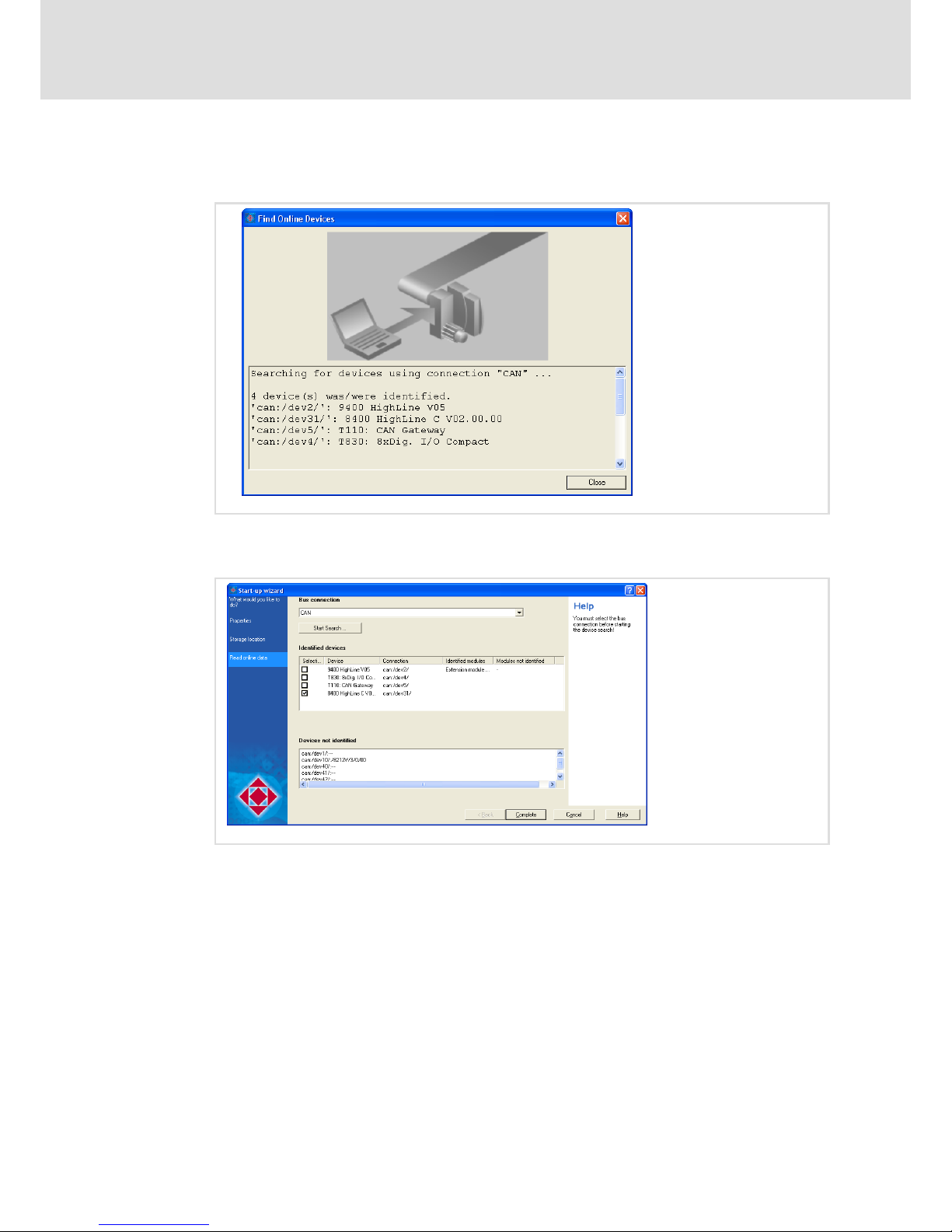
Operation
Communicating via the CAN gateway function
Establishing communication using the L−force Engineer
8
76
LDCDS−EL100 EN 8.0
6. Click the Device search button to find connected devices.
In the case of a successful search, all devices are identified.
EL100−045
7. Click Close.
8. In the "Selection" column, deselect all devices that you do not wish to parameterise.
EL100−046
Page 77
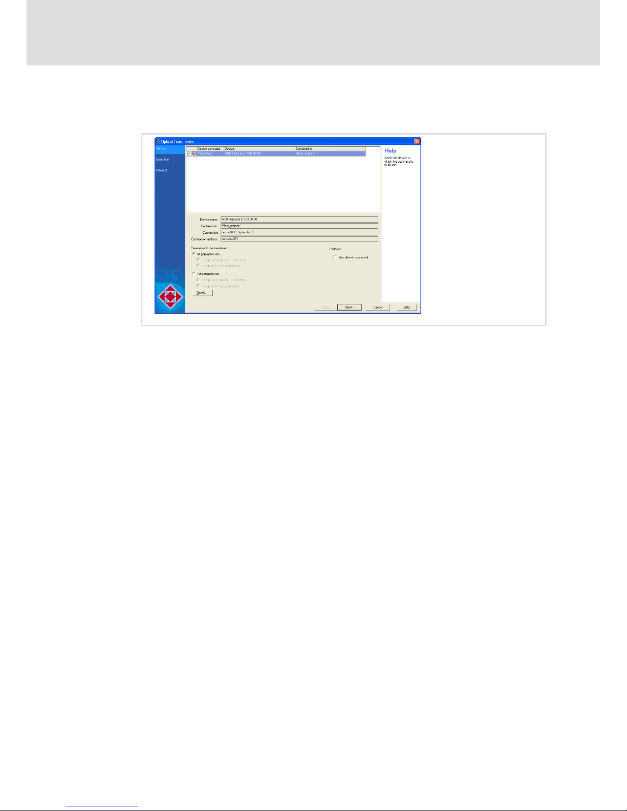
Operation
Communicating via the CAN gateway function
Establishing communication using the L−force Engineer
8
77
LDCDS−EL100 EN 8.0
9. Click Complete.
The "Upload from device" window is displayed.
EL100−047
10. Set the parameters to be transmitted here.
11. Click Next.
The parameters are transmitted. In the case of a successful transmission, an online
connection to the 8400 frequency inverter has been established.
The frequency inverter can now be parameterised.
Page 78
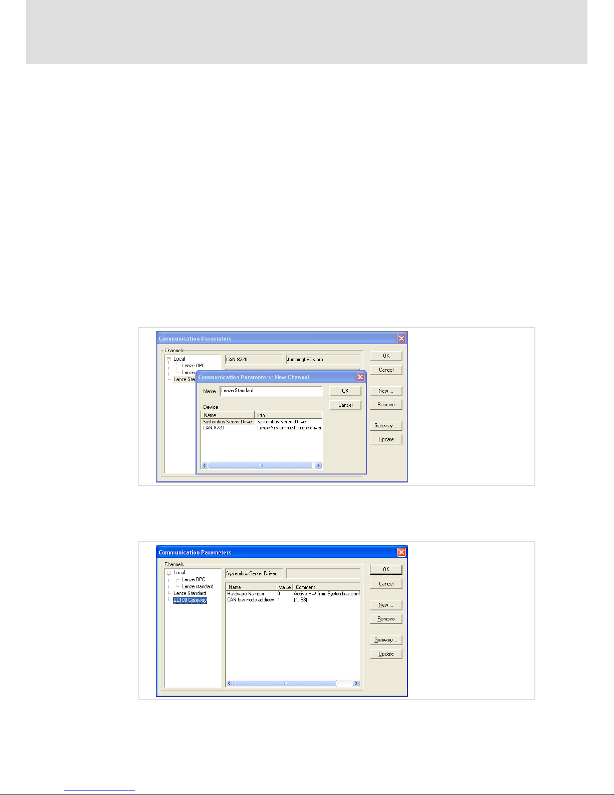
Operation
Communicating via the CAN gateway function
Establishing communication using the Drive PLC Developer Studio (DDS)
8
78
LDCDS−EL100 EN 8.0
8.5.5 Establishing communication using the Drive PLC Developer Studio (DDS)
The used bus system must be selected for the communication via the EL100
communication module. System bus−specific settings can be made on the EL100 module
in the "CAN Gateway" applet. The communication module can only be selected via the
system bus configurator.
Commissioning is illustrated by the following example. The parameter data of an 8400
frequency inverter are to be displayed using the Engineer.
How to proceed:
1. Start the Drive PLC Developer Studio (DDS) program and open the project to be
transferred via the EL100 communication module.
2. Activate the Online ® Communication parameters menu item.
The "Communication parameters" window is displayed. Here, the settings regarding
communication via the EL100 module can be made.
3. Click New to set a new channel.
4. Select the "Systembus Server Driver" for the EL100 communication module.
5. Assign an arbitrary name to the channel (e.g. EL100 Gateway).
6. Click OK.
A new channel is created.
Page 79
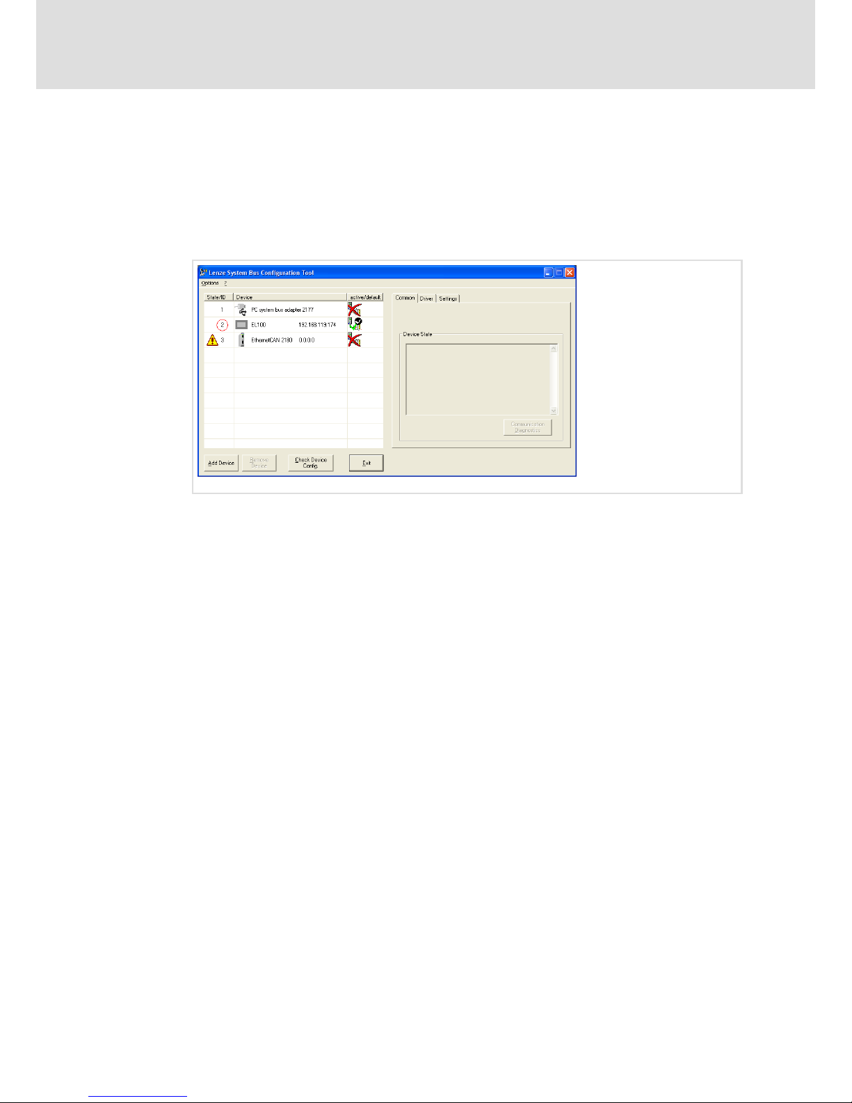
Operation
Communicating via the CAN gateway function
Establishing communication using the Drive PLC Developer Studio (DDS)
8
79
LDCDS−EL100 EN 8.0
7. Set the hardware number of the EL100 communication module and the node
address of the node to be programmed.
The hardware number can be found in the system bus configurator. This number is
assigned to the communication module.
If you have added several communication modules in the system bus configurator, you
must specify the number of the module via which you would like to communicate. For
this purpose, double−click the value (highlighted in red).
EL100−050
8. Please also enter the node address of the node via which you would like to access
the EL100 communication module.
Communication between the DDS and the system bus node via the communication
module has now been established.
Page 80

Maintenance
General notes
9
80
LDCDS−EL100 EN 8.0
9 Maintenance
9.1 General notes
The device is free of maintenance. Nevertheless, visual inspections should be carried out
at regular intervals which must not be too long, depending on the ambient conditions.
Please check the following:
ƒ Does the environment of the device meet the operating conditions specified in the
Technical data?
ƒ Is the heat dissipation of the device not impeded by dust or dirt?
ƒ Are the mechanical and electrical connections o.k.?
9.2 Battery replacement
Danger!
Danger of fire and explosion
On the baseboard there is a battery for buffering the clock (RTC) when the
device has been switched off.
Possible consequences:
ƒ The use of other batteries than the approved ones or improper handling can
result in a fire, explosion, or environmental damage.
Protective measures:
ƒ The battery may only be replaced by an approved battery type according to
the following list.
ƒ The battery may not be recharged or opened. Furthermore it may not be
thrown into a fire or be heated above 100 °C (212 °F).
Approved types:
ƒ Matsushita CR2450, Renata CR2450N, Sony Corp. CR2450B, Toshiba CR2450, Varta
CR2450
Page 81

Maintenance
Battery replacement
9
81
LDCDS−EL100 EN 8.0
How to proceed:
1. Remove all connected cables and the SD card.
2. Remove the device and put it face−down on a table.
Make sure that the display is not damaged by parts on the table.
3. Remove PC housing:
0
1
1
1
1
0
0
2
3
0
EL100−035
– Loosen 4 screws . Do not loosen screw !
– Loosen 4 screws .
– Carefully remove the housing . Please observe that the housing is connected to
the baseboard by a cable (PE connection ).
4. Exchange battery:
4
EL100−036
– Remove the dead battery from the unit.
– Insert new battery with the positive pole up.
5. Mount PC housing:
– Carefully put the housing onto the baseboard. The PE cable must not be bent in
the process.
– Insert and tighten 4 screws and 4 screws .
According to European legislation you are obliged to dispose of batteries separately, using
the take−back systems specified.
Page 82

Index10
82
LDCDS−EL100 EN 8.0
10 Index
A
AddFont.exe, 38
Ambient conditions
− climatic, 15
− Shock, 15
− Vibration, 15
Applet
− CAN Gateway Configuration, 45
− display, 43
− Fieldbus, 44
− MPI Config, 45
− Registry, 42
− Server, 44
− StartUp, 41
− VisiWinNET, 43
Application as directed, 12
Approbation, 15
C
Cable fixing, 28 , 30
CAN interface, 35
COM connection, 26
Commissioning, 31
− connecting devices, 31
− Initial switch−on, 32
Conformity, 15
Connecting devices, 31
Connections, overview, 13 , 14 , 31
Control Panel
− CAN Gateway Configuration, 45
− Fieldbus, 44
− MPI Config, 45
− Registry, 42
− Server, 44
− StartUp, 41
− VisiWinNET, 43
Control panel, display, 43
Create PLC program, create, 50
Create sym file, 53
D
Definition of notes used, 8
Definitions, 7
Dimensions, 21 , 22
Disposal, 11
E
Electrical data, 16
Electrical installation, 24
− COM, 26
− EMC−compliant wiring, 24
− Ethernet, 26 , 29
− LAN, 26 , 29
− Mains, 25 , 29
− RS232, 26
− USB, internal, 26 , 29
− USB connection, 26
EMC
− earthing, 24
− shielding, 24
− structure, 24
EMC−compliant wiring, 24
Establish Connection, 35
Ethernet connection, 26 , 29
Example, PLC program, 49
F
FTP Server, 65
I
Initial switch−on, 32
Installation, CE−typical drive system
− earthing, 24
− shielding, 24
− structure, 24
Installation, electrical, 24
Installation, mechanical, 23
Installing fonts, 38
Interface
− CAN, 35
− LAN, 33
− MPI, 36
L
LAN connection, 26 , 29
LAN interface, 33
Page 83

Index 10
83
LDCDS−EL100 EN 8.0
M
Mains connection, 25 , 29
Maintenance, 80
Mechanical data, 21
− Dimensions, 21 , 22
− dimensions, 21 , 22
− weight, 21 , 22
Mechanical installation, 23
Monitor connection, 26
Mounting conditions
− Mounting place, 15
− mounting position, 15
MPI interface, 36
N
Network
− CAN, 35
− LAN, 33
− MPI, 36
Notes, definition, 8
O
Operating conditions
− Ambient conditions
Shock, 15
Vibration, 15
− ambient conditions, climatic, 15
− Mounting conditions, Mounting place, 15
− mounting conditions, mounting position, 15
Operating system components, 39
Operation, 39
P
PLC Designer
− CAN communication, 57
− Create PLC program, 50
− Create sym file, 53
− start, 50
− Start program, 57
− Transfer program, 55
PLC program, 49
− CAN communication, 57
− create, 49
− Create sym file, 53
− Example, 49
− start, 57
− Start PLC Designer, 50
− transfer, 55
Product description, 12
− application as directed, 12
Programming, 49
R
RAS Server, 68
RS232 connection, 26
S
Safety instructions, 9
− application as directed, 12
− definition, 8
− General, 9
− layout, 8
Scope of supply, 13
Server
− Enable Access, 63
− Overview, 62
− Password, 64
Shielding, EMC, 24
Shock resistance, 15
Strain relief, 28 , 30
Switch on, initial, 32
T
Technical data, 15
− Electrical data, 16
− mechanical data, 21
Telnet Server, 66
Type of protection, 15
U
Uninterruptible Power System, 37
UPS, 37
USB connection, 26
− internal, 26 , 29
V
Vibration resistance, 15
VNC Server, 67
W
Web Server (SysAdmin), 65
Weight, 21 , 22
Page 84

© 01/2012
F
Lenze Automation GmbH
Hans−Lenze−Str. 1
D−31855 Aerzen
Germany
Service Lenze Service GmbH
Breslauer Straße 3
D−32699 Extertal
Germany
(
+49(0)51 54 /82−0
(
008000/ 2446877 (24 h helpline)
Ê
+49(0)51 54 /82 − 28 00
Ê
+49(0)5154/ 82−11 12
ü
www.Lenze.com
LDCDS−EL100 § .Hv| § EN § 8.0 § TD29
10987654321
 Loading...