

Page 1
EDK82ZAFLC−001
.A30
Ä.A30ä
L−force Communication
Montageanleitung
Mounting Instructions
Instructions de montage
LECOM−B
E82ZAFLC001
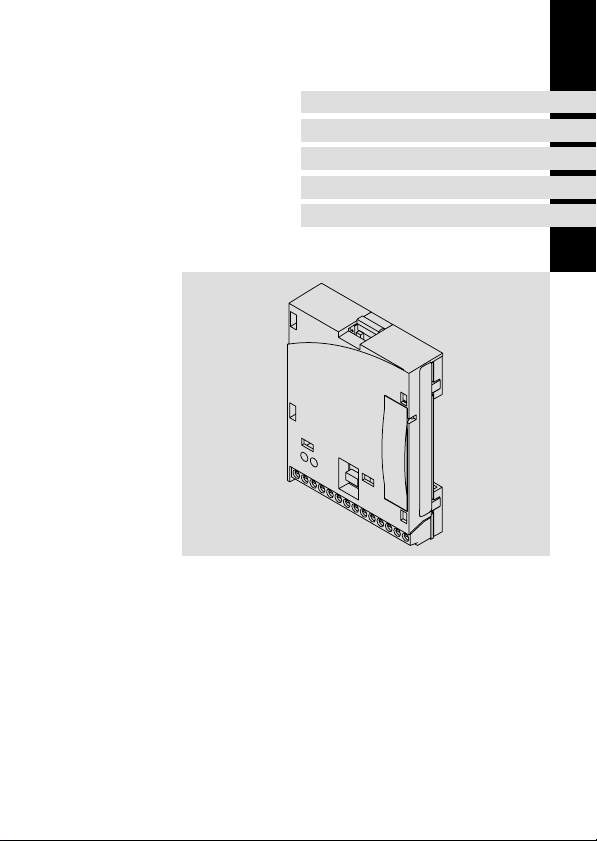
Funktionsmodul
Function module
Module de fonction
Page 2

Lesen Sie zuerst diese Anleitung und die Dokumentation zum Grundgerät,
bevor Sie mit den Arbeiten beginnen!
Beachten Sie die enthaltenen Sicherheitshinweise.
Please read these instructions and the documentation of the standard
device before you start working!
Observe the safety instructions given therein!
Lire le présent fascicule et la documentation relative à l’appareil de base
avant toute manipulation de l’équipement !
Respecter les consignes de sécurité fournies.
Page 3
E82ZAFLC011B
Page 4

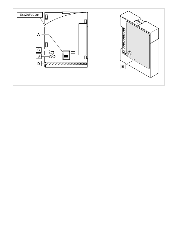
Legende zur Abbildung auf der Ausklappseite
Pos. Beschreibung Ausführliche
Funktionsmodul E82ZAFLC001
DIP−Schalter zur Aktivierung des Busabschluss−Widerstandes
Statusanzeige (gelb) Kommunikation LECOM−B
Statusanzeige (grün) Kommunikation Antrieb
Klemmenleiste X3, Anschlüsse für
l LECOM−B
l Reglersperre (CINH)
l externe Spannungsversorgung
Typenschild 13
0Abb. 0Tab. 0
Information
25
29
21
4
EDK82ZAFLC−001 DE/EN/FR 5.0
Page 5

Inhalt i
1 Über diese Dokumentation 6 . . . . . . . . . . . . . . . . . . . . . . . . . . . . . . . . . . . . . . . . . . . .
Verwendete Konventionen 7 . . . . . . . . . . . . . . . . . . . . . . . . . . . . . . . . . . . . . . . . . . . .
Verwendete Hinweise 8 . . . . . . . . . . . . . . . . . . . . . . . . . . . . . . . . . . . . . . . . . . . . . . . .
2 Sicherheitshinweise 10 . . . . . . . . . . . . . . . . . . . . . . . . . . . . . . . . . . . . . . . . . . . . . . . . . .
3 Produktbeschreibung 11 . . . . . . . . . . . . . . . . . . . . . . . . . . . . . . . . . . . . . . . . . . . . . . . .
Funktion 11 . . . . . . . . . . . . . . . . . . . . . . . . . . . . . . . . . . . . . . . . . . . . . . . . . . . . . . . . . . .
Bestimmungsgemäße Verwendung 11 . . . . . . . . . . . . . . . . . . . . . . . . . . . . . . . . . . . .
Lieferumfang 12 . . . . . . . . . . . . . . . . . . . . . . . . . . . . . . . . . . . . . . . . . . . . . . . . . . . . . . .
Identifikation 13 . . . . . . . . . . . . . . . . . . . . . . . . . . . . . . . . . . . . . . . . . . . . . . . . . . . . . . .
4 Technische Daten 14 . . . . . . . . . . . . . . . . . . . . . . . . . . . . . . . . . . . . . . . . . . . . . . . . . . . .
Allgemeine Daten und Einsatzbedingungen 14 . . . . . . . . . . . . . . . . . . . . . . . . . . . .
Schutzisolierung 16 . . . . . . . . . . . . . . . . . . . . . . . . . . . . . . . . . . . . . . . . . . . . . . . . . . . . .
Abmessungen 17 . . . . . . . . . . . . . . . . . . . . . . . . . . . . . . . . . . . . . . . . . . . . . . . . . . . . . . .
5 Mechanische Installation 18 . . . . . . . . . . . . . . . . . . . . . . . . . . . . . . . . . . . . . . . . . . . . .
6 Elektrische Installation 19 . . . . . . . . . . . . . . . . . . . . . . . . . . . . . . . . . . . . . . . . . . . . . . .
EMV−gerechte Verdrahtung 19 . . . . . . . . . . . . . . . . . . . . . . . . . . . . . . . . . . . . . . . . . . .
Daten der Anschlussklemmen 20 . . . . . . . . . . . . . . . . . . . . . . . . . . . . . . . . . . . . . . . . .
Spannungsversorgung 21 . . . . . . . . . . . . . . . . . . . . . . . . . . . . . . . . . . . . . . . . . . . . . . . .
Verdrahtung des LECOM−B−Netzwerkes 23 . . . . . . . . . . . . . . . . . . . . . . . . . . . . . . . . .
7 Inbetriebnahme 24 . . . . . . . . . . . . . . . . . . . . . . . . . . . . . . . . . . . . . . . . . . . . . . . . . . . . .
Vor dem ersten Einschalten 24 . . . . . . . . . . . . . . . . . . . . . . . . . . . . . . . . . . . . . . . . . . .
Busabschluss−Widerstand aktivieren 25 . . . . . . . . . . . . . . . . . . . . . . . . . . . . . . . . . . . .
Erstes Einschalten 26 . . . . . . . . . . . . . . . . . . . . . . . . . . . . . . . . . . . . . . . . . . . . . . . . . . .
8 Diagnose 29 . . . . . . . . . . . . . . . . . . . . . . . . . . . . . . . . . . . . . . . . . . . . . . . . . . . . . . . . . . .
LED−Statusanzeigen 29 . . . . . . . . . . . . . . . . . . . . . . . . . . . . . . . . . . . . . . . . . . . . . . . . .
EDK82ZAFLC−001 DE/EN/FR 5.0
5
Page 6

1 Über diese Dokumentation
1 Über diese Dokumentation
Inhalt
Diese Dokumentation enthält ...
ƒ Sicherheitshinweise, die Sie unbedingt beachten müssen;
ƒ Angaben über Versionsstände der zu verwendenden Lenze Grundgeräte;
ƒ Informationen zur mechanischen und elektrischen Installation des Funktionsmoduls;
ƒ Informationen zur Inbetriebnahme und Diagnose.
Informationen zur Gültigkeit
Die Informationen in dieser Dokumentation sind gültig für folgende Geräte:
ƒ Funktionsmodule E82ZAFLC001, LECOM−B, ab Version 3A.10.
Zielgruppe
Diese Dokumentation richtet sich an Personen, die die Vernetzung und Fernwartung einer
Maschine projektieren, installieren, in Betrieb nehmen und warten.
Tipp!
Dokumentationen und Software−Updates zu weiteren Lenze Produkten finden
Sie im Internet im Bereich "Services & Downloads" unter
http://www.Lenze.com
6
EDK82ZAFLC−001 DE/EN/FR 5.0
Page 7

Über diese Dokumentation
Verwendete Konventionen
Verwendete Konventionen
Diese Dokumentation verwendet folgende Konventionen zur Unterscheidung verschiedener Arten von Information:
Informationsart Auszeichnung Beispiele/Hinweise
Zahlenschreibweise
Dezimaltrennzeichen
Symbole
Seitenverweis
Punkt Es wird generell der Dezimalpunkt
verwendet.
Beispiel: 1234.56
Verweis auf eine andere Seite mit zusätzlichen Informationen
Beispiel: 16 = siehe Seite 16
1
EDK82ZAFLC−001 DE/EN/FR 5.0
7
Page 8

1 Über diese Dokumentation
Verwendete Hinweise
Verwendete Hinweise
Um auf Gefahren und wichtige Informationen hinzuweisen, werden in dieser Dokumentation folgende Piktogramme und Signalwörter verwendet:
Sicherheitshinweise
Aufbau der Sicherheitshinweise:
Gefahr!
(kennzeichnet die Art und die Schwere der Gefahr)
Hinweistext
(beschreibt die Gefahr und gibt Hinweise, wie sie vermieden werden kann)
Piktogramm und Signalwort Bedeutung
Gefahr von Personenschäden durch gefährliche elektrische Spannung
Gefahr!
Gefahr!
Stop!
Hinweis auf eine unmittelbar drohende Gefahr, die den
Tod oder schwere Verletzungen zur Folge haben kann,
wenn nicht die entsprechenden Maßnahmen getroffen
werden.
Gefahr von Personenschäden durch eine allgemeine Gefahrenquelle
Hinweis auf eine unmittelbar drohende Gefahr, die den
Tod oder schwere Verletzungen zur Folge haben kann,
wenn nicht die entsprechenden Maßnahmen getroffen
werden.
Gefahr von Sachschäden
Hinweis auf eine mögliche Gefahr, die Sachschäden zur
Folge haben kann, wenn nicht die entsprechenden Maßnahmen getroffen werden.
8
EDK82ZAFLC−001 DE/EN/FR 5.0
Page 9

Anwendungshinweise
Piktogramm und Signalwort Bedeutung
Über diese Dokumentation
Verwendete Hinweise
1
Hinweis!
Tipp!
Wichtiger Hinweis für die störungsfreie Funktion
Nützlicher Tipp für die einfache Handhabung
Verweis auf andere Dokumentation
EDK82ZAFLC−001 DE/EN/FR 5.0
9
Page 10

2 Sicherheitshinweise
2 Sicherheitshinweise
Gefahr!
Unsachgemäßer Umgang mit dem Funktionsmodul und dem Grundgerät kann
schwere Personenschäden und Sachschäden verursachen.
Beachten Sie die in der Dokumentation zum Grundgerät enthaltenen
Sicherheitshinweise und Restgefahren.
Stop!
Elektrostatische Entladung
Durch elektrostatische Entladung können elektronische Bauteile innerhalb des
Funkionsmoduls beschädigt oder zerstört werden.
Mögliche Folgen:
ƒ Das Funktionsmodul ist defekt.
ƒ Die Feldbus−Kommunikation ist nicht möglich oder fehlerhaft.
Schutzmaßnahmen
ƒ Befreien Sie sich vor dem Berühren des Moduls von elektrostatischen
Aufladungen.
10
EDK82ZAFLC−001 DE/EN/FR 5.0
Page 11

Produktbeschreibung
Funktion
3 Produktbeschreibung
Funktion
Das Funktionsmodul koppelt Lenze−Antriebsregler über den Lenze−Feldbus LECOM−B
(RS485) an einen übergeordneten Leitrechner (SPS, PC).
Bestimmungsgemäße Verwendung
Das Funktionsmodul E82ZAFLC001 ...
ƒ ist ein Betriebsmittel zum Einsatz in industriellen Starkstromanlagen;
ƒ ist eine Zubehör−Baugruppe, die mit folgenden Lenze Grundgeräten eingesetzt
werden kann:
Grundgerät ab Version
Frequenzumrichter 8200 vector Vx14
8200 motec Vx14
Jede andere Verwendung gilt als sachwidrig!
3
EDK82ZAFLC−001 DE/EN/FR 5.0
11
Page 12
3 Produktbeschreibung
Lieferumfang
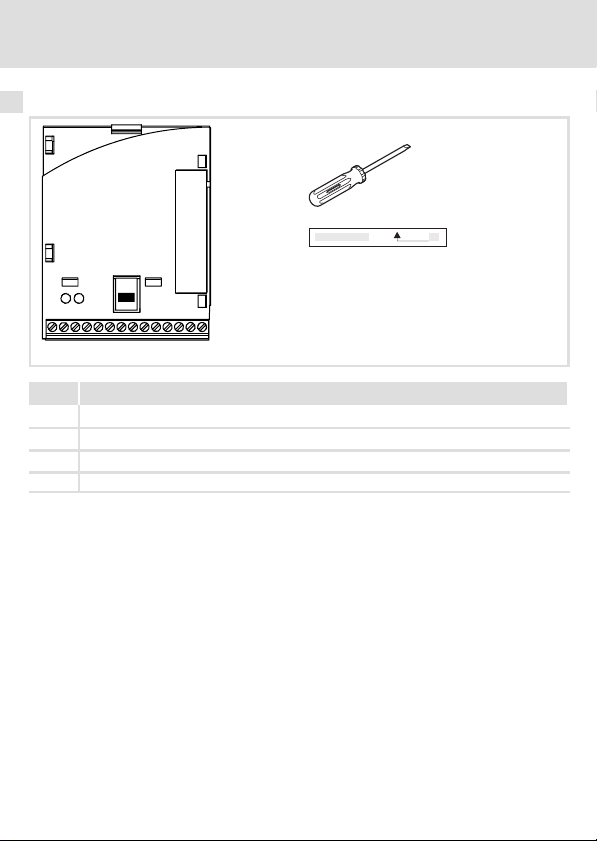
Lieferumfang
Pos. Lieferumfang
Funktionsmodul E82ZAFLC001
Montageanleitung
Schraubendreher
Klebestreifen
Tipp!
Weiterführende Informationen zu diesem Funktionsmodul finden Sie im
entsprechenden Kommunikationshandbuch.
Die PDF−Datei finden Sie im Internet im Bereich "Services & Downloads" unter
http://www.Lenze.com
E82ZAFP004/E82ZAFL011B
12
EDK82ZAFLC−001 DE/EN/FR 5.0
Page 13
Identifikation
APPLICATION
010 / 3A22
Produktbeschreibung
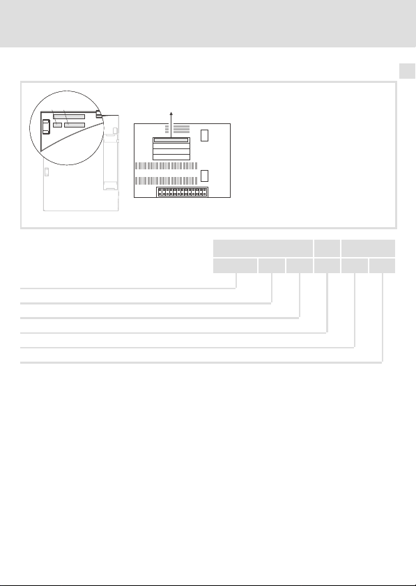
Identifikation
3
APPLICATION
010/ 3A22
Gerätereihe
LECOM−B
Gerätegeneration
Variante 001: verlackte Ausführung
Hardwarestand
Softwarestand
L
Type
Id.-No.
Prod.-No.
Ser.-No.
E82AF000P0B201XX
E82ZAFX005
E82ZAF L C 001 3A 10
EDK82ZAFLC−001 DE/EN/FR 5.0
13
Page 14
4 Technische Daten
Allgemeine Daten und Einsatzbedingungen
4 Technische Daten
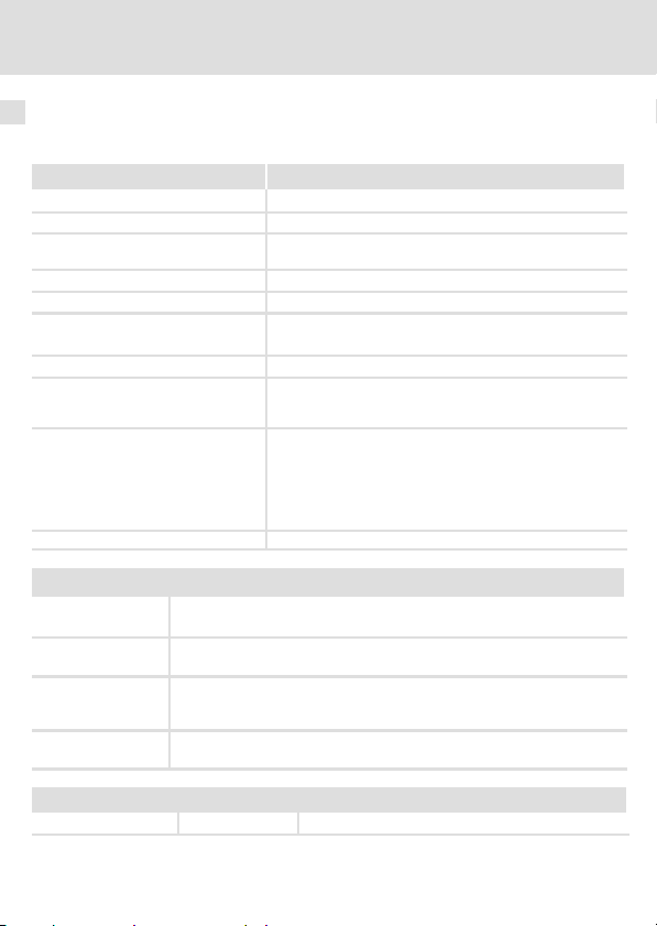
Allgemeine Daten und Einsatzbedingungen
Allgemeine Daten
Bereich Werte
Kommunikationsprotokoll LECOM−A/B V2.0
Kommunikationsmedium RS485 (LECOM−B)
Übertragungszeichenformat 7E1: 7 Bit ASCII, 1 Stopp−Bit, 1 Start−Bit, 1 Paritäts−Bit
Übertragungsrate [kBit/s] 1200, 2400, 4800, 9600, 19200, 38400, 57600
LECOM−B−Teilnehmer Slave
Netzwerk−Topologie
max. Anzahl Teilnehmer Standard: 31 (= 1 Bus−Segment) / mit Repeatern: 90
max. Leitungslänge pro Bus−Segment 1000 m
Kommunikationszeit
Externe DC−Spannungsversorgung +24 V DC ±10 %, max. 80 mA
Klemmenleiste X3/
VP Pegel: 5 V (Bezug: GND3)
28 Externe Versorgung der Klemme mit
20 DC−Spannungsquelle zur internen Versorgung der Reglersperre (CINH)
59 Externe Versorgung des Funktionsmoduls mit
Belastbarkeit: I
U(ext.) = +12 V DC − 0% ... +30 V DC + 0%
U = + 20 V (Bezug: GND1),
= 10 mA
I
max
U(ext.) = +24 V DC
(gerade)
l ohne Repeater: Linie
l mit Repeatern: Linie oder Baum
(abhängig von Übertragungsrate und verwendetem Kabeltyp)
l Summe aus der Zykluszeit und der Bearbeitungszeit in
den Feldbusteilnehmern. Die Zeiten sind unabhängig
voneinander.
l Bearbeitungszeit im Antriebsregler:
– Parameterdaten: ca. 30 ms + 20 ms Toleranz
– Prozessdaten: ca. 3 ms + 2 ms Toleranz
= 10 mA
max
± 10%
Personenschutz und Geräteschutz
Schutzart
EN 60529 IP20
14
EDK82ZAFLC−001 DE/EN/FR 5.0
Page 15

Allgemeine Daten und Einsatzbedingungen
Technische Daten
Einsatzbedingungen
Umgebungsbedingungen
Klimatisch
Lagerung IEC/EN 60721−3−1 1K3 (−25 ... +60 °C)
Transport IEC/EN 60721−3−2 2K3 (−25 ... +70 °C)
Betrieb Entsprechend der Daten des verwendeten Lenze Grundgerätes (siehe
Verschmutzung EN 61800−5−1 Verschmutzungsgrad 2
Dokumentation des Grundgerätes).
4
EDK82ZAFLC−001 DE/EN/FR 5.0
15
Page 16

4 Technische Daten
Schutzisolierung
Schutzisolierung
Isolierung zwischen Bus und ... Art der Isolierung (nach EN61800−5−1)
l Leistungsteil
– 8200 vector Verstärkte Isolierung
– 8200 motec Verstärkte Isolierung
l Bezugserde / PE (X3/7) Betriebsisolierung
l externe Versorgung (X3/59) Betriebsisolierung
l Steuerklemmen
– X3/20 (interne Versorgung) Betriebsisolierung
– X3/28 (Reglersperre (CINH)) Betriebsisolierung
16
EDK82ZAFLC−001 DE/EN/FR 5.0
Page 17
Abmessungen
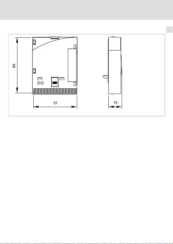
alle Maße in mm
Technische Daten
Abmessungen
E82ZAFL011B
4
EDK82ZAFLC−001 DE/EN/FR 5.0
17
Page 18

5 Mechanische Installation
5 Mechanische Installation
Folgen Sie zur mechanischen Installation des Funktionsmoduls den Hinweisen in der Montageanleitung des Grundgerätes.
Die Montageanleitung des Grundgerätes ...
ƒ ist Teil des Lieferumfangs und liegt jedem Gerät bei.
ƒ gibt Hinweise, um Beschädigungen durch unsachgemäße Behandlung zu vermeiden.
ƒ beschreibt die einzuhaltende Reihenfolge der Installationsschritte.
18
EDK82ZAFLC−001 DE/EN/FR 5.0
Page 19

Elektrische Installation
EMV−gerechte Verdrahtung
6 Elektrische Installation
EMV−gerechte Verdrahtung
Für eine EMV−gerechte Verdrahtung beachten Sie folgende Punkte:
Hinweis!
ƒ Steuer−/Datenleitungen getrennt von Motorleitungen verlegen.
ƒ Legen Sie die Schirme der Steuer−/Datenleitungen bei digitalen Signalen
beidseitig auf.
ƒ Zur Vermeidung von Potenzialdifferenzen zwischen den
Kommunikationsteilnehmern eine Ausgleichsleitung mit einem
Querschnitt von mindestens 16mm
ƒ Beachten Sie die weiteren Hinweise zur EMV−gerechten Verdrahtung in der
Dokumentation des Grundgerätes.
Vorgehensweise bei der Verdrahtung
1. Bustopologie einhalten, deshalb keine Stichleitungen verwenden.
2. Hinweise und Verdrahtungsvorschriften in den Unterlagen zum Steuerungssystem
beachten.
3. Nur Kabel verwenden, die den aufgeführten Spezifikationen entsprechen (23).
4. Hinweise zur Spannungsversorgung des Funktionsmoduls beachten (21).
5. Busabschluss−Widerstände am physikalisch ersten und letzten Teilnehmer aktivieren
(25).
2
einsetzen (Bezug:PE).
6
EDK82ZAFLC−001 DE/EN/FR 5.0
19
Page 20
6 Elektrische Installation
Daten der Anschlussklemmen
Daten der Anschlussklemmen
Bereich Werte
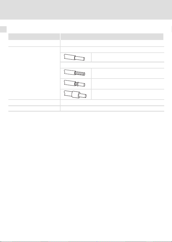
Elektrischer Anschluss Klemmenleiste mit Schraubanschluss
Anschlussmöglichkeiten
Anzugsmoment 0.22 ... 0.25 Nm (1.9 ... 2.2 lb−in)
Abisolierlänge 5 mm
starr:
flexibel:
2
1.5 mm
(AWG 16)
ohne Aderendhülse
2
(AWG 18)
1.0 mm
mit Aderendhülse, ohne Kunststoffhülse
2
(AWG 20)
0.5 mm
mit Aderendhülse, mit Kunststoffhülse
2
(AWG 20)
0.5 mm
20
EDK82ZAFLC−001 DE/EN/FR 5.0
Page 21

Elektrische Installation
Spannungsversorgung
Spannungsversorgung
Hinweis!
Verwenden Sie bei externer Spannungsversorgung und bei größeren
Entfernungen zwischen den Schaltschränken in jedem Schaltschrank immer
ein separates und nach EN 61800−5−1 sicher getrenntes Netzteil
("SELV"/"PELV").
DC−Spannungsversorgung
Intern Die interne Spannung steht an Klemme X3.3/20 zur Verfügung. Sie dient der Versor-
Extern Die externe Spannungsversorgung des Funktionsmoduls ist notwendig, wenn beim
X3/ Bezeichnung Funktion Pegel
A T/R(A) RS485 Datenleitung A
B T/R(B) RS485 Datenleitung B
CN CNTR *) Beim Senden von Daten:
VP *) +5 V (Bezug: GND3)
40 GND3 Bezugspotenzial für LECOM−B−Netzwerk
7 GND1 Bezugspotenzial für die interne
39 GND2 Bezugspotenzial der Reglersperre
28 CINH Reglersperre
20 DC−Spannungsquelle zur internen Ver-
gung der Reglersperre (CINH).
Ausfall der Versorgung des Grundgerätes die Kommunikation bestehen bleiben soll.
Zusätzlicher HF−Schirmabschluss
CNTR = HIGH
+5 V (Bezug: GND3)
*)
Versorgung an X3/20
(CINH) an X3/28
l Start = HIGH (+12 ... +30 V)
l Stopp = LOW (0 ... +3 V)
sorgung der Reglersperre (CINH)
+20 V (Bezug: GND1)
6
59 Externe DC−Versorgung des
*) z. B. bei Anschluss eines Repeaters
EDK82ZAFLC−001 DE/EN/FR 5.0
Funktionsmoduls
U(ext.) =+24VDC±10%
(Bezug: GND1)
21
Page 22
6 Elektrische Installation
Spannungsversorgung
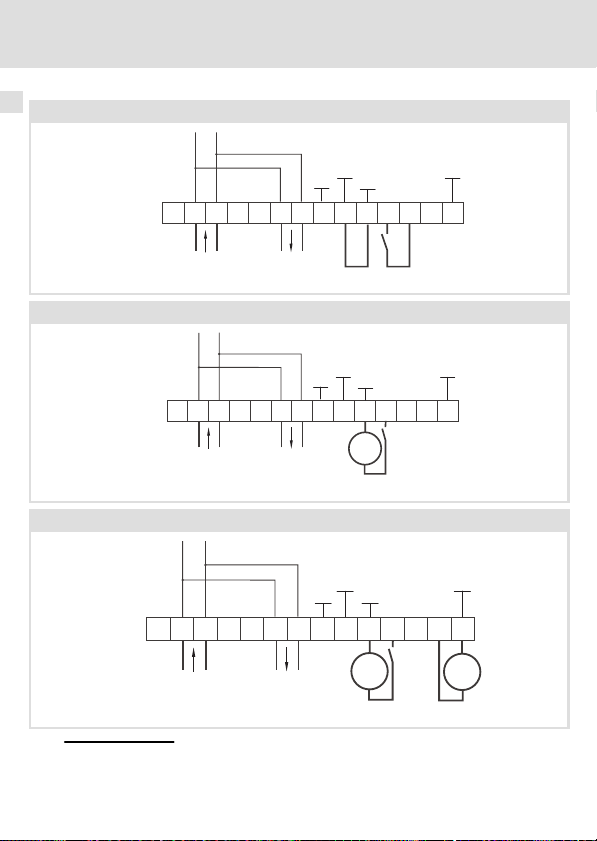
Versorgung der Reglersperre (CINH) über die interne Spannungsquelle (X3/20)
2839
28397
+20V
20 59
+20V
20 59
+20V
GND1
59
GND1
7
7
GND1
720
E82ZAFP001
E82ZAFP002
_
+
E82ZAFP003
GND1
GND3
BA
BA
40
GND3
40
GND3
40
7
GND1
7
GND1
GND2
GND2
_
+
GND2
_
+
2839
+5V
B
AVP
+
X3
T/R(A) T/R(B) T/R(A) T/R(B)
Versorgung der Reglersperre (CINH) über die externe Spannungsquelle
X3
Versorgung des Funktionsmoduls und der Reglersperre (CINH) über die externe Spannungsquelle
+
X3
T/R(A) T/R(B) T/R(A) T/R(B)
CN
+5V
B
AVP
CN
+
T/R(A) T/R(B) T/R(A) T/R(B)
+5V
VP
A
B
CN
Für den Betrieb notwendige Mindestverdrahtung
BA
22
EDK82ZAFLC−001 DE/EN/FR 5.0
Page 23
Verdrahtung des LECOM−B−Netzwerkes
Verdrahtung des LECOM−B−Netzwerkes
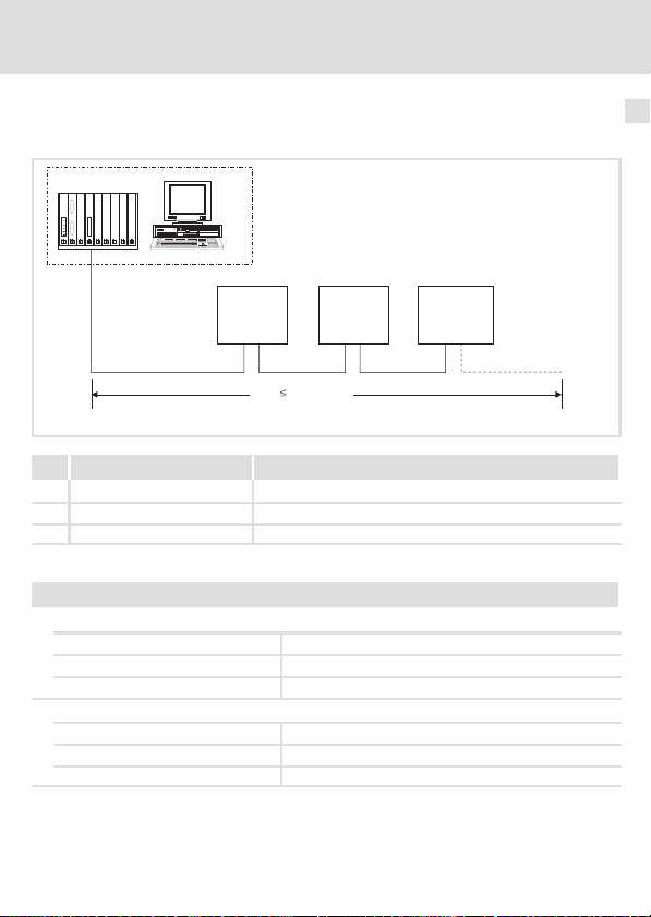
Prinzipieller Aufbau eines LECOM−B−Netzwerks
1
333
SSS
Elektrische Installation
6
222
1000 m
0m
E82ZAFL005
Nr. Element Bemerkung
1 Leitrechner Z. B. PC oder SPS mit RS485−Master−Anschaltbaugruppe
2 Buskabel Max. Länge: 1000 m
3 LECOM−B−Slave Einsetzbares Grundgerät mit Funktionsmodul E82ZAFLC0xx
Spezifikation des Übertragungskabels
Spezifikation Übertragungskabel für RS485
l Gesamtleitungslänge bis 300 m:
Kabeltyp
Leitungswiderstand £ 40 W/km
Kapazitätsbelag £ 130 nF/km
l Gesamtleitungslänge bis 1200 m:
Kabeltyp CYPIMF 1 x 2 x 0.5 mm2 abgeschirmt
Leitungswiderstand £ 40 W/km
Kapazitätsbelag £ 130 nF/km
EDK82ZAFLC−001 DE/EN/FR 5.0
LIYCY 1 x 2 x 0.5 mm2 abgeschirmt
23
Page 24

7 Inbetriebnahme
Vor dem ersten Einschalten
7 Inbetriebnahme
Vor dem ersten Einschalten
Stop!
Bevor Sie das Grundgerät mit dem Funktionsmodul erstmalig einschalten,
überprüfen Sie ...
ƒ die gesamte Verdrahtung auf Vollständigkeit, Kurzschluss und Erdschluss.
ƒ ob das Bussystem beim physikalisch ersten und letzten Busteilnehmer
durch den integrierten aktiven Busabschluss−Widerstand (25)
abgeschlossen ist.
24
EDK82ZAFLC−001 DE/EN/FR 5.0
Page 25
Busabschluss−Widerstand aktivieren
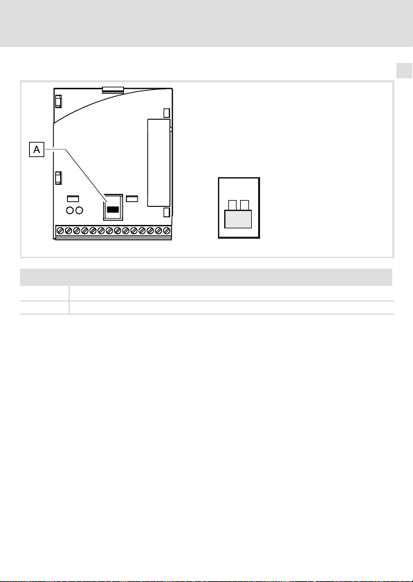
Busabschluss−Widerstand aktivieren
Inbetriebnahme
ON
7
DIP−Schalter
ON Integrierter Busabschluss−Widerstand aktiv.
OFF Integrierter Busabschluss−Widerstand nicht aktiv.
EDK82ZAFLC−001 DE/EN/FR 5.0
E82ZAFL011B / E82ZAFP010
25
Page 26

7 Inbetriebnahme
Erstes Einschalten
Erstes Einschalten
Hinweis!
ƒ Das Grundgerät ist nur funktionsfähig, wenn ein HIGH−Pegel an der
Anschlussklemme 28 anliegt (Reglerfreigabe über Klemme).
– Beachten Sie, dass die Reglersperre über mehrere Quellen gesetzt
werden kann. Die Quellen wirken wie eine Reihenschaltung von
Schaltern.
– Wenn der Antrieb trotz Reglerfreigabe über die Anschlussklemme 28
nicht anläuft, überprüfen Sie, ob noch über eine andere Quelle die
Reglersperre gesetzt ist. Eine andere Quelle könnte z. B. die −Taste
des Keypad XT sein.
ƒ Beachten Sie die gegenüber der Softwareversion "0.1" geänderten
Statusinformationen der Codestelle C0068 (siehe folgende Tabelle).
Bit Funktion Beschreibung
8 RFR (Reglerfreigabe) 0: Keine Reglerfreigabe
11 IMP (Impulssperre) 0: Impulse für Leistungsteile gesperrt
15 TRIP (Störung) 0: Keine Störung
1: Reglerfreigabe
1: Impulse für Leistungsteile freigegeben
1: Störung vorhanden
26
EDK82ZAFLC−001 DE/EN/FR 5.0
Page 27

Inbetriebnahme
Erstes Einschalten
Inbetriebnahmeschritte
Schritt Beschreibung
1. Leitsystem für die Kommunikation mit dem Funktionsmodul konfigurieren.
2. Busabschluss überprüfen.
l Nur beim ersten und letzten Busteilnehmer:
l Busabschlusswiderstand mit DIP−Schalter = ON aktivieren (25)
Lenze−Einstellung: OFF
3. Netzspannung zuschalten und ggf. separate Spannungsversorgung des Funktionsmoduls
zuschalten.
l Das Grundgerät ist nach ca. 1 Sekunde betriebsbereit.
l Die Reglersperre ist aktiv.
Reaktion:
l Die grüne LED auf der Frontseite des Funktionsmoduls leuchtet (nur sichtbar beim 8200
vector, 29).
l Keypad XT: (falls aufgesteckt)
Hinweis zu Schritt 4. und 5.
Wenn Sie die Stationsadresse (C1509) und die LECOM−Übertragungsrate (C1516) über das Leitsystem
einstellen, müssen Sie die Einstellungen des Leitrechners sofort ändern. Der Leitrechner würde sonst
die Antworten nicht erkennen, da diese schon mit den neuen Einstellungen vom Antriebsregler
gesendet werden.
4. Stationsadresse zuweisen.
l Dem Busteilnehmer mit C1509 eine Stationsadresse zuweisen.
l Jeder Busteilnehmer benötigt eine andere Adresse.
Lenze−Einstellung: 1
5. LECOM−Übertragungsrate über Keypad XT oder Leitsystem einstellen.
Lenze−Einstellung: 9600 Bit/s
Nun können Sie mit dem Antriebsregler kommunizieren, d. h. Sie können alle Codestellen lesen und
alle beschreibbaren Codestellen verändern.
6. Weitere erforderliche Einstellungen am Antriebsregler vornehmen (sieheDokumentation
des Antriebsreglers).
Reaktion:
l Die gelbe LED auf dem Funktionsmodul blinkt, wenn der LECOM−B aktiv ist (29).
7. Funktionsmodul als Sollwertquelle wählen.
l Sollwertquelle: C0046
l Konfiguration: C0412/1 = 0
7
EDK82ZAFLC−001 DE/EN/FR 5.0
27
Page 28

7 Inbetriebnahme
Erstes Einschalten
BeschreibungSchritt
8. Antriebsregler über Klemme freigeben.
l Klemme 28 = HIGH
9. Sollwert vorgeben über C0046
Der Antrieb läuft jetzt an.
28
EDK82ZAFLC−001 DE/EN/FR 5.0
Page 29

8 Diagnose
LED−Statusanzeigen
Pos. Farbe Zustand Beschreibung
+
gelb
grün
gelb/
grün
aus
blinkt Die Kommunikation über das Funktionsmodul zum Leitsystem ist
aus
blinkt Das Funktionsmodul ist mit Spannung versorgt, hat aber keine Ver-
an Das Funktionsmodul ist mit Spannung versorgt und hat eine Verbin-
blinkt Interner Fehler des Funktionsmoduls
l Keine Kommunikation mit dem Leitsystem
l Das Funktionsmodul wird nicht mit Spannung versorgt.
aufgebaut.
l Das Funktionsmodul wird nicht mit Spannung versorgt.
l Das Grundgerät und/oder die externe Spannungsversorgung ist
ausgeschaltet.
bindung zum Grundgerät.
Mögliche Ursachen:
l Das Grundgerät ist ausgeschaltet.
l Das Grundgerät ist in der Initialisierungsphase.
l Das Grundgerät ist nicht vorhanden.
dung zum Grundgerät.
Diagnose
LED−Statusanzeigen
8
EDK82ZAFLC−001 DE/EN/FR 5.0
29
Page 30

Legend for fold−out page
Pos. Description Detailed
E82ZAFLC001 function module
DIP switch for activating the bus terminating resistor
Status display (yellow), LECOM−B communication
Status display (green), drive communication
Terminal strip X3, connections for
l LECOM−B
l Controller inhibit (CINH)
l External voltage supply
Nameplate 39
0Fig. 0Tab. 0
information
51
54
47
30
EDK82ZAFLC−001 DE/EN/FR 5.0
Page 31

Contents i
1 About this documentation 32 . . . . . . . . . . . . . . . . . . . . . . . . . . . . . . . . . . . . . . . . . . . .
Conventions used 33 . . . . . . . . . . . . . . . . . . . . . . . . . . . . . . . . . . . . . . . . . . . . . . . . . . . .
Notes used 34 . . . . . . . . . . . . . . . . . . . . . . . . . . . . . . . . . . . . . . . . . . . . . . . . . . . . . . . . .
2 Safety instructions 36 . . . . . . . . . . . . . . . . . . . . . . . . . . . . . . . . . . . . . . . . . . . . . . . . . . .
3 Product description 37 . . . . . . . . . . . . . . . . . . . . . . . . . . . . . . . . . . . . . . . . . . . . . . . . . .
Function 37 . . . . . . . . . . . . . . . . . . . . . . . . . . . . . . . . . . . . . . . . . . . . . . . . . . . . . . . . . . .
Application as directed 37 . . . . . . . . . . . . . . . . . . . . . . . . . . . . . . . . . . . . . . . . . . . . . . .
Scope of supply 38 . . . . . . . . . . . . . . . . . . . . . . . . . . . . . . . . . . . . . . . . . . . . . . . . . . . . . .
Identification 39 . . . . . . . . . . . . . . . . . . . . . . . . . . . . . . . . . . . . . . . . . . . . . . . . . . . . . . .
4 Technical data 40 . . . . . . . . . . . . . . . . . . . . . . . . . . . . . . . . . . . . . . . . . . . . . . . . . . . . . . .
General data and operating conditions 40 . . . . . . . . . . . . . . . . . . . . . . . . . . . . . . . .
Protective insulation 42 . . . . . . . . . . . . . . . . . . . . . . . . . . . . . . . . . . . . . . . . . . . . . . . . .
Dimensions 43 . . . . . . . . . . . . . . . . . . . . . . . . . . . . . . . . . . . . . . . . . . . . . . . . . . . . . . . . .
5 Mechanical installation 44 . . . . . . . . . . . . . . . . . . . . . . . . . . . . . . . . . . . . . . . . . . . . . . .
6 Electrical installation 45 . . . . . . . . . . . . . . . . . . . . . . . . . . . . . . . . . . . . . . . . . . . . . . . . .
Wiring according to EMC 45 . . . . . . . . . . . . . . . . . . . . . . . . . . . . . . . . . . . . . . . . . . . . . .
Connection terminals 46 . . . . . . . . . . . . . . . . . . . . . . . . . . . . . . . . . . . . . . . . . . . . . . . .
Voltage supply 47 . . . . . . . . . . . . . . . . . . . . . . . . . . . . . . . . . . . . . . . . . . . . . . . . . . . . . .
Wiring of the LECOM−B network 49 . . . . . . . . . . . . . . . . . . . . . . . . . . . . . . . . . . . . . . . .
7 Commissioning 50 . . . . . . . . . . . . . . . . . . . . . . . . . . . . . . . . . . . . . . . . . . . . . . . . . . . . .
Before switching on 50 . . . . . . . . . . . . . . . . . . . . . . . . . . . . . . . . . . . . . . . . . . . . . . . . .
Activating the bus terminating resistor 51 . . . . . . . . . . . . . . . . . . . . . . . . . . . . . . . . . .
Initial switch−on 52 . . . . . . . . . . . . . . . . . . . . . . . . . . . . . . . . . . . . . . . . . . . . . . . . . . . . .
8 Diagnostics 54 . . . . . . . . . . . . . . . . . . . . . . . . . . . . . . . . . . . . . . . . . . . . . . . . . . . . . . . . .
LED status displays 54 . . . . . . . . . . . . . . . . . . . . . . . . . . . . . . . . . . . . . . . . . . . . . . . . . .
EDK82ZAFLC−001 DE/EN/FR 5.0
31
Page 32

1 About this documentation
1 About this documentation
Contents
This documentation provides ...
ƒ Safety instructions that must be observed;
ƒ Information about the versions of the Lenze standard devices to be used;
ƒ Information about the mechanical and electrical installation of the function module;
ƒ Information about commissioning and diagnostics.
Validity information
The information given in this documentation is valid for the following devices:
ƒ E82ZAFLC001 function modules, LECOM−B, as of version 3A.10.
Target group
This documentation addresses to persons who project, install, commission, and maintain
the networking and remote maintenance of a machine.
Tip!
Documentation and software updates for further Lenze products can be found
on the Internet in the "Services & Downloads" area under
http://www.Lenze.com
32
EDK82ZAFLC−001 DE/EN/FR 5.0
Page 33

About this documentation
Conventions used
Conventions used
This documentation uses the following conventions to distinguish between different types
of information:
Type of information Identification Examples/notes
Numbers
Decimal separator
Symbols
Page reference
Point The decimal point is used throughout
this documentation.
Example: 1234.56
Reference to another page with
additional information
Example: 16 = see page 16
1
EDK82ZAFLC−001 DE/EN/FR 5.0
33
Page 34

1 About this documentation
Notes used
Notes used
The following pictographs and signal words are used in this documentation to indicate
dangers and important information:
Safety instructions
Structure of safety instructions:
Danger!
(characterises the type and severity of danger)
Note
(describes the danger and gives information about how to prevent dangerous
situations)
Pictograph and signal word Meaning
Danger of personal injury through dangerous electrical
Danger!
Danger!
Stop!
voltage.
Reference to an imminent danger that may result in
death or serious personal injury if the corresponding
measures are not taken.
Danger of personal injury through a general source of
danger.
Reference to an imminent danger that may result in
death or serious personal injury if the corresponding
measures are not taken.
Danger of property damage.
Reference to a possible danger that may result in
property damage if the corresponding measures are not
taken.
34
EDK82ZAFLC−001 DE/EN/FR 5.0
Page 35

Application notes
Pictograph and signal word Meaning
About this documentation
Notes used
1
Note!
Tip!
Important note to ensure troublefree operation
Useful tip for simple handling
Reference to another documentation
EDK82ZAFLC−001 DE/EN/FR 5.0
35
Page 36

2 Safety instructions
2 Safety instructions
Danger!
Inappropriate handling of the function module and the standard device can
cause serious injuries to persons and damage to material assets.
Observe the safety instructions and residual hazards included in the
documentation of the standard device.
Stop!
Electrostatic discharge
Electronic components within the function module can be damaged or
destroyed by electrostatic discharge.
Possible consequences:
ƒ The function module is defective.
ƒ Fieldbus communication is not possible or faulty.
Protective measures
ƒ Free yourself from any electrostatic charge before you touch the module.
36
EDK82ZAFLC−001 DE/EN/FR 5.0
Page 37

Product description
Function
3 Product description
Function
The function module connects the Lenze controller to a higher−level master computer (PLC,
PC) via the Lenze fieldbus LECOM−B (RS485).
Application as directed
The E82ZAFLC001 function module ...
ƒ is a device for the use in industrial power systems;
ƒ is an accessory module for use in conjunction with the following Lenze standard
devices:
Standard device From version
Frequency inverter 8200 vector Vx14
8200 motec Vx14
Any other use shall be deemed inappropriate!
3
EDK82ZAFLC−001 DE/EN/FR 5.0
37
Page 38

3 Product description
Scope of supply
Scope of supply
Pos. Scope of supply
E82ZAFLC001 function module
Mounting Instructions
Screwdriver
Adhesive tape
Tip!
More information about this function module is available in the corresponding
communication manual.
The PDF file can be downloaded from the Internet in the "Services &
Downloads" area at
http://www.Lenze.com
E82ZAFP004/E82ZAFL011B
38
EDK82ZAFLC−001 DE/EN/FR 5.0
Page 39

Identification
APPLICATION
010 / 3A22
Product description
Identification
3
APPLICATION
010/ 3A22
Device series
LECOM−B
Version
Variant 001: coated design
Hardware version
Software version
L
Type
Id.-No.
Prod.-No.
Ser.-No.
E82AF000P0B201XX
E82ZAFX005
E82ZAF L C 001 3A 10
EDK82ZAFLC−001 DE/EN/FR 5.0
39
Page 40

4 Technical data
General data and operating conditions
4 Technical data
General data and operating conditions
General data
Range Values
Communication protocol LECOM−A/B V2.0
Communication medium RS485 (LECOM−B)
Character format: 7E1: 7 bit ASCII, 1 stop bit, 1 start bit, 1 parity bit (even)
Baud rate [kbit/s] 1200, 2400, 4800, 9600, 19200, 38400, 57600
LECOM−B station Slave
Network topology
Max. number of stations Standard: 31 (= 1 bus segment) / with repeaters: 90
Max. cable length per bus segment 1000 m
Communication time
External DC voltage supply +24 V DC ±10 %, max. 80 mA
Terminal strip X3/
VP Level: 5 V (reference: GND3)
28 External terminal supply
20 DC voltage source for internal supply of the controller inhibit (CINH)
59 External function module supply
Load capacity: I
U(ext.) = +12 V DC − 0% ... +30 V DC + 0%
U = + 20 V (reference: GND1),
= 10 mA
I
max
U(ext.) = +24 V DC
l without repeaters: line
l with repeaters: line or tree
(depending on baud rate and cable type used)
l Sum of cycle time and processing time in the fieldbus
stations. The times are independent of each other.
l Processing time in the controller:
– Parameter data: approx. 30 ms + 20 ms tolerance
– Process data: approx. 3 ms + 2 ms tolerance
= 10 mA
max
± 10%
Protection of persons and equipment
Type of protection
EN 60529 IP20
40
EDK82ZAFLC−001 DE/EN/FR 5.0
Page 41

General data and operating conditions
Technical data
Operating conditions
Ambient conditions
Climate
Storage IEC/EN 60721−3−1 1K3 (−25 to +60 °C)
Transport IEC/EN 60721−3−2 2K3 (−25 to +70 °C)
Operation Corresponding to the data of the Lenze standard device used (see
Pollution EN 61800−5−1 Degree of pollution 2
documentation of the standard device).
4
EDK82ZAFLC−001 DE/EN/FR 5.0
41
Page 42

4 Technical data
Protective insulation
Protective insulation
Insulation between bus and ... Type of insulation (in accordance with
l Power section
– 8200 vector Reinforced insulation
– 8200 motec Reinforced insulation
l Reference earth / PE (X3/7) Functional insulation
l External supply (X3/59) Functional insulation
l Control terminals
– X3/20 (internal supply) Functional insulation
– X3/28 (controller inhibit (CINH)) Functional insulation
EN61800−5−1)
42
EDK82ZAFLC−001 DE/EN/FR 5.0
Page 43

Dimensions
All dimensions in mm
Technical data
Dimensions
E82ZAFL011B
4
EDK82ZAFLC−001 DE/EN/FR 5.0
43
Page 44

5 Mechanical installation
5 Mechanical installation
Follow the notes given in the Mounting Instructions for the standard device for the
mechanical installation of the function module.
The Mounting Instructions for the standard device ...
ƒ are part of the scope of supply and are enclosed with each device.
ƒ provide tips for avoiding damage through improper handling.
ƒ describe the obligatory order of installation steps.
44
EDK82ZAFLC−001 DE/EN/FR 5.0
Page 45

Electrical installation
Wiring according to EMC
6 Electrical installation
Wiring according to EMC
For wiring according to EMC requirements observe the following points:
Note!
ƒ Separate control cables/data lines from motor cables.
ƒ Connect the shields of control cables/data lines at both ends in the case of
digital signals.
ƒ Use an equalizing conductor with a cross−section of at least 16mm
(reference:PE) to avoid potential differences between the bus nodes.
ƒ Observe the other notes concerning EMC−compliant wiring given in the
documentation for the standard device.
Wiring procedure
1. Observe bus topology, so do not use any stubs.
2. Follow the wiring notes given in the documentation for the control system.
3. Only use cables which comply with the specifications listed (49).
4. Follow the notes on the voltage supply for the function module (47).
5. Activate the bus terminating resistors on the first and last physical node (51).
2
6
EDK82ZAFLC−001 DE/EN/FR 5.0
45
Page 46

6 Electrical installation
Connection terminals
Connection terminals
Range Values
Electrical connection Terminal strip with screw connection
Possible connections
Tightening torque 0.22 ... 0.25 Nm (1.9 ... 2.2 lb−in)
Bare end 5 mm
rigid:
flexible:
2
1.5 mm
(AWG 16)
without wire end ferrule
2
(AWG 18)
1.0 mm
with wire end ferrule, without plastic sleeve
2
(AWG 20)
0.5 mm
with wire end ferrule, with plastic sleeve
2
(AWG 20)
0.5 mm
46
EDK82ZAFLC−001 DE/EN/FR 5.0
Page 47

Electrical installation
Voltage supply
Voltage supply
Note!
Always use a separate power supply unit in every control cabinet and safely
separate it according to EN 61800−5−1 ("SELV"/"PELV") in the case of external
voltage supply and larger distances between the control cabinets.
DC voltage supply
Internal The internal voltage is provided at terminal X3.3/20. It serves to supply the
External The external voltage supply of the function module is required if communication is
X3/ Designation Function Level
A T/R(A) RS485 data line A
B T/R(B) RS485 data line B
CN CNTR *) During data transmission:
VP *) +5 V (reference: GND3)
40 GND3 Reference potential for LECOM−B
7 GND1 Reference potential for the internal
39 GND2 Reference potential of controller inhibit
28 CINH Controller inhibit
20 DC voltage source for internal supply of
controller inhibit (CINH).
to be maintained during a failure of the standard device supply.
Additional HF−shield termination
CNTR = HIGH
+5 V (reference: GND3)
network *)
supply at X3/20
(CINH) at X3/28
l Start = HIGH (+12 ... +30 V)
l Stop = LOW (0 ... +3 V)
controller inhibit (CINH)
+20 V (reference: GND1)
6
59 External DC supply for the function
*) e.g. if a repeater is connected
EDK82ZAFLC−001 DE/EN/FR 5.0
module
U(ext.) =+24VDC±10%
(reference: GND1)
47
Page 48

6 Electrical installation
Voltage supply
Supply of the controller inhibit (CINH) via the internal voltage source (X3/20)
2839
28397
+20V
20 59
+20V
20 59
+20V
GND1
59
GND1
7
7
GND1
720
_
+
GND1
GND3
BA
BA
40
GND3
40
GND3
40
7
GND1
7
GND1
GND2
GND2
_
+
GND2
_
+
2839
+5V
B
AVP
+
X3
T/R(A) T/R(B) T/R(A) T/R(B)
Supply of the controller inhibit (CINH) via the external voltage supply
X3
Supply of the function module and controller inhibit (CINH) via the external voltage source
+
X3
T/R(A) T/R(B) T/R(A) T/R(B)
CN
+5V
B
AVP
CN
+
T/R(A) T/R(B) T/R(A) T/R(B)
+5V
VP
A
B
CN
Minimum wiring required for operation
BA
E82ZAFP001
E82ZAFP002
E82ZAFP003
48
EDK82ZAFLC−001 DE/EN/FR 5.0
Page 49

Wiring of the LECOM−B network
Basic structure of a LECOM−B network
1
333
SSS
Electrical installation
Wiring of the LECOM−B network
6
222
1000 m
0m
No. Element Comment
1 Master computer E.g. PC or PLC with RS485 master interface module
2 Bus cable Max. length: 1000 m
3 LECOM−B slave Standard device applicable with E82ZAFLC0xx function
Specification of the transmission cable
Specification of transmission cable for RS485
l Total cable length up to 300 m:
Cable type
Cable resistance £ 40 W/km
Capacitance per unit length £ 130 nF/km
l Total cable length up to 1200 m:
Cable type CYPIMF 1 x 2 x 0.5 mm2 shielded
Cable resistance £ 40 W/km
Capacitance per unit length £ 130 nF/km
EDK82ZAFLC−001 DE/EN/FR 5.0
module
LIYCY 1 x 2 x 0.5 mm2 shielded
E82ZAFL005
49
Page 50

7 Commissioning
Before switching on
7 Commissioning
Before switching on
Stop!
Before switching on the standard device with the function module for the first
time, check ...
ƒ the entire wiring with regard to completeness, short circuit, and earth
fault.
ƒ whether the bus system is terminated at the first and last physical node by
the integrated active bus terminating resistor. (51)
50
EDK82ZAFLC−001 DE/EN/FR 5.0
Page 51

Activating the bus terminating resistor
Activating the bus terminating resistor
ON
Commissioning
7
DIP switch
ON Integrated bus terminating resistor active.
OFF Integrated bus terminating resistor not active.
EDK82ZAFLC−001 DE/EN/FR 5.0
E82ZAFL011B / E82ZAFP010
51
Page 52

7 Commissioning
Initial switch−on
Initial switch−on
Note!
ƒ The standard device is only ready for operation if a HIGH level is applied to
terminal 28 (controller enable via terminal).
– Please note that the controller can be inhibited by various sources. The
sources act like a series connection of switches.
– If the drive does not start even though the controller has been enabled
via terminal 28, check whether the controller has been inhibited by
another source. Another source could be the key of the XT keypad.
ƒ Please note the different status information for code C0068 compared to
software version "0.1" (see the following table).
Bit Function Description
8 RFR (controller enable) 0: no controller enable
11 IMP (pulse inhibit) 0: pulses for power sections inhibited
15 TRIP (fault) 0: no fault
1: controller enable
1: pulses for power sections enabled
1: fault exists
52
EDK82ZAFLC−001 DE/EN/FR 5.0
Page 53

Commissioning
Initial switch−on
Commissioning steps
Step Description
1. Configure host system for communication with the function module.
2. Check bus termination.
l Only for the first and last node:
l Activate bus terminating resistor with DIP switch = ON (51)
Lenze setting: OFF
3. Connect mains voltage and, if necessary, separate voltage supply for the function module.
l After approx. 1 second the standard device will be ready for operation.
l Controller inhibit is active.
Response:
l The green LED on the front of the function module is lit (only visible in the case of 8200
vector, 54).
l XT keypad: (if plugged in)
Note regarding steps 4. and 5.
If you set the station address (C1509) and the LECOM baud rate (C1516) via the host system, the
settings of the master computer must be changed immediately. Otherwise the master computer
would not recognise the responses since they are already sent with the new settings by the
controller.
4. Assign station address.
l Assign a station address to the node withC1509.
l Each node requires its own address.
Lenze setting: 1
5. Set LECOM baud rate via XT keypad or host system.
Lenze setting: 9600 bits/s
Communication with the controller is now possible, i.e. all codes can be read and all writable codes
can be changed.
6. Carry out further required settings on the controller (see documentation of the controller).
Response:
l The yellow LED on the function module blinks if LECOM−B is active (54).
7. Select function module as setpoint source.
l Setpoint source: C0046
l Configuration: C0412/1 = 0
8. Enable controller via terminal.
l Terminal 28 = HIGH
9. Specify setpoint via C0046
The drive starts up.
7
EDK82ZAFLC−001 DE/EN/FR 5.0
53
Page 54

8 Diagnostics
LED status displays
8 Diagnostics
LED status displays
Pos. Colour Status Description
+
yellow
green
yellow /
green
off
blinking Communication via the function module to the host system has
off
blinking The function module is supplied with voltage but is not connected to
on The function module is supplied with voltage and is connected to the
blinking Internal error of the function module
l No communication with the host system
l The function module is not supplied with voltage.
been established.
l The function module is not supplied with voltage.
l The standard device and/or the external voltage supply is/are
switched off.
the standard device.
Possible causes:
l The standard device is switched off.
l The standard device is in the initialisation phase.
l The standard device is not available.
standard device.
54
EDK82ZAFLC−001 DE/EN/FR 5.0
Page 55

Diagnostics
LED status displays
8
EDK82ZAFLC−001 DE/EN/FR 5.0
55
Page 56

Légende de l’illustration de la page dépliante
Pos. Description Informations
Module de fonction E82ZAFLC001
Interrupteur DIP pour l’activation de la résistance d’extrémité de bus
Indicateur d’état (jaune) de la communication via LECOM−B
Indicateur d’état (vert) de la communication avec l’entraînement
Bornier X3, raccordements pour
l LECOM−B
l blocage variateur (CINH)
l alimentation externe
Plaque signalétique 65
0Fig. 0Tab. 0
détaillées
78
82
74
56
EDK82ZAFLC−001 DE/EN/FR 5.0
Page 57

Sommaire i
1 Présentation du document 58 . . . . . . . . . . . . . . . . . . . . . . . . . . . . . . . . . . . . . . . . . . . .
Conventions utilisées 59 . . . . . . . . . . . . . . . . . . . . . . . . . . . . . . . . . . . . . . . . . . . . . . . . .
Consignes utilisées 60 . . . . . . . . . . . . . . . . . . . . . . . . . . . . . . . . . . . . . . . . . . . . . . . . . . .
2 Consignes de sécurité 62 . . . . . . . . . . . . . . . . . . . . . . . . . . . . . . . . . . . . . . . . . . . . . . . .
3 Description du produit 63 . . . . . . . . . . . . . . . . . . . . . . . . . . . . . . . . . . . . . . . . . . . . . . . .
Fonction 63 . . . . . . . . . . . . . . . . . . . . . . . . . . . . . . . . . . . . . . . . . . . . . . . . . . . . . . . . . . .
Utilisation conforme à la fonction 63 . . . . . . . . . . . . . . . . . . . . . . . . . . . . . . . . . . . . . .
Equipement livré 64 . . . . . . . . . . . . . . . . . . . . . . . . . . . . . . . . . . . . . . . . . . . . . . . . . . . .
Identification 65 . . . . . . . . . . . . . . . . . . . . . . . . . . . . . . . . . . . . . . . . . . . . . . . . . . . . . . .
4 Spécifications techniques 66 . . . . . . . . . . . . . . . . . . . . . . . . . . . . . . . . . . . . . . . . . . . . .
Caractéristiques générales et conditions d’utilisation 66 . . . . . . . . . . . . . . . . . . . .
Isolement de protection 68 . . . . . . . . . . . . . . . . . . . . . . . . . . . . . . . . . . . . . . . . . . . . . .
Encombrements 69 . . . . . . . . . . . . . . . . . . . . . . . . . . . . . . . . . . . . . . . . . . . . . . . . . . . . .
5 Installation mécanique 70 . . . . . . . . . . . . . . . . . . . . . . . . . . . . . . . . . . . . . . . . . . . . . . .
6 Installation électrique 71 . . . . . . . . . . . . . . . . . . . . . . . . . . . . . . . . . . . . . . . . . . . . . . . .
Câblage conforme CEM 71 . . . . . . . . . . . . . . . . . . . . . . . . . . . . . . . . . . . . . . . . . . . . . . .
Spécifications des bornes de raccordement 72 . . . . . . . . . . . . . . . . . . . . . . . . . . . . . .
Alimentation 73 . . . . . . . . . . . . . . . . . . . . . . . . . . . . . . . . . . . . . . . . . . . . . . . . . . . . . . . .
Câblage du réseau LECOM−B 76 . . . . . . . . . . . . . . . . . . . . . . . . . . . . . . . . . . . . . . . . . . .
7 Mise en service 77 . . . . . . . . . . . . . . . . . . . . . . . . . . . . . . . . . . . . . . . . . . . . . . . . . . . . . .
Avant la première mise sous tension 77 . . . . . . . . . . . . . . . . . . . . . . . . . . . . . . . . . . . .
Activation de la résistance d’extrémité de bus 78 . . . . . . . . . . . . . . . . . . . . . . . . . . .
Première mise en service 79 . . . . . . . . . . . . . . . . . . . . . . . . . . . . . . . . . . . . . . . . . . . . . .
8 Diagnostic 82 . . . . . . . . . . . . . . . . . . . . . . . . . . . . . . . . . . . . . . . . . . . . . . . . . . . . . . . . . .
Affichages d’état par LED 82 . . . . . . . . . . . . . . . . . . . . . . . . . . . . . . . . . . . . . . . . . . . . .
EDK82ZAFLC−001 DE/EN/FR 5.0
57
Page 58

1 Présentation du document
1 Présentation du document
Contenu
Le présent document contient ...
ƒ des consignes de sécurité à respecter impérativement ;
ƒ des renseignements sur les versions des appareils de base Lenze à utiliser ;
ƒ des informations sur l’installation mécanique et électrique du module de fonction ;
ƒ des informations sur la mise en service et le diagnostic.
Informations relatives à la validité
Les informations contenues dans le présent document s’appliquent aux appareils suivants :
ƒ modules de fonction E82ZAFLC001, LECOM−B, à partir de la version 3A.10.
Public visé
Ce document s’adresse aux personnes chargées de la conception, de l’installation, de la
mise en service et de la maintenance de la connexion au réseau et de la télémaintenance
d’une machine.
Conseil !
Les mises à jour de logiciels et les documentations relatives aux produits Lenze
sont disponibles dans la zone "Téléchargements" du site Internet :
http://www.Lenze.com
58
EDK82ZAFLC−001 DE/EN/FR 5.0
Page 59

Présentation du document
Conventions utilisées
Conventions utilisées
Pour faire la distinction entre différents types d’informations, ce document utilise les
conventions suivantes :
Type d’information Marquage Exemples/remarques
Représentation des chiffres
Séparateur décimal
Symboles
Renvoi à une page
Point Le point décimal est généralement
utilisé.
Exemple : 1234.56
Renvoi à une autre page présentant
des informations supplémentaires
Exemple : 16 = voir page 16
1
EDK82ZAFLC−001 DE/EN/FR 5.0
59
Page 60

1 Présentation du document
Consignes utilisées
Consignes utilisées
Pour indiquer des risques et des informations importantes, la présente documentation
utilise les mots et symboles suivants :
Consignes de sécurité
Présentation des consignes de sécurité
Danger !
(Le pictogramme indique le type de risque.)
Explication
(L’explication décrit le risque et les moyens de l’éviter.)
Pictogramme et mot associé Explication
Situation dangereuse pour les personnes en raison d’une
tension électrique élevée
Danger !
Danger !
Stop !
Indication d’un danger imminent qui peut avoir pour
conséquences des blessures mortelles ou très graves en
cas de non−respect des consignes de sécurité
correspondantes
Situation dangereuse pour les personnes en raison d’un
danger d’ordre général
Indication d’un danger imminent qui peut avoir pour
conséquences des blessures mortelles ou très graves en
cas de non−respect des consignes de sécurité
correspondantes
Risques de dégâts matériels
Indication d’un risque potentiel qui peut avoir pour
conséquences des dégâts matériels en cas de non−respect
des consignes de sécurité correspondantes
60
EDK82ZAFLC−001 DE/EN/FR 5.0
Page 61

Consignes d’utilisation
Pictogramme et mot associé Explication
Présentation du document
Consignes utilisées
1
Remarque
importante !
Conseil !
Remarque importante pour assurer un fonctionnement
correct
Conseil utile pour faciliter la mise en oeuvre
Référence à une autre documentation
EDK82ZAFLC−001 DE/EN/FR 5.0
61
Page 62

2 Consignes de sécurité
2 Consignes de sécurité
Danger !
L’utilisation non conforme à la fonction du module de fonction et de l’appareil
de base peut entraîner de graves dommages corporels et matériels.
Tenir compte des consignes de sécurité et des dangers résiduels énoncés dans
la documentation de l’appareil de base.
Stop !
Décharges électrostatiques
Les décharges électrostatiques peuvent endommager ou détruire les
composants électroniques situés à l’intérieur du module de fonction.
Risques encourus :
ƒ Module de fonction en panne
ƒ La communication par bus de terrain est impossible ou erronée.
Mesures de protection :
ƒ Avant d’entrer en contact avec le module, veillez à vous libérer de toute
charge électrostatique.
62
EDK82ZAFLC−001 DE/EN/FR 5.0
Page 63

Description du produit
Fonction
3 Description du produit
Fonction
Le module de fonction permet de relier les variateurs de vitesse Lenze via le bus de terrain
Lenze LECOM−B (RS485) à un système maître (API, PC).
Utilisation conforme à la fonction
Le module de fonction E82ZAFLC001 ...
ƒ est un matériel d’exploitation destiné à être utilisé dans les installations industrielles
à courant fort ;
ƒ est un accessoire compatible avec les appareils de base Lenze suivants :
Appareil de base à partir de la version
Convertisseur de fréquence 8200 vector Vx14
8200 motec Vx14
Toute autre utilisation est contre−indiquée !
3
EDK82ZAFLC−001 DE/EN/FR 5.0
63
Page 64

3 Description du produit
Equipement livré
Equipement livré
Pos. Equipement livré
Module de fonction E82ZAFLC001
Instructions de montage
Tournevis
Bandes autocollantes
Conseil !
Pour plus d’informations sur ce module de fonction, consulter le manuel de
communication correspondant.
Le fichier PDF peut être téléchargé sur Internet dans la zone "Services &
Downloads" de notre site à l’adresse suivante :
http://www.Lenze.com
E82ZAFP004/E82ZAFL011B
64
EDK82ZAFLC−001 DE/EN/FR 5.0
Page 65

Identification
APPLICATION
010 / 3A22
Description du produit
Identification
3
APPLICATION
010/ 3A22
Série d’appareils
LECOM−B
Génération d’appareils
Variante 001 : variante vernie
Version matérielle
Version logicielle
L
Type
Id.-No.
Prod.-No.
Ser.-No.
E82AF000P0B201XX
E82ZAFX005
E82ZAF L C 001 3A 10
EDK82ZAFLC−001 DE/EN/FR 5.0
65
Page 66

4 Spécifications techniques
Caractéristiques générales et conditions d’utilisation
4 Spécifications techniques
Caractéristiques générales et conditions d’utilisation
Caractéristiques générales
Domaine Valeurs
Protocole de communication LECOM−A/B V2.0
Support de communication RS485 (LECOM−B)
Format de caractère de transmission 7E1 : 7 bits ASCII, 1 bit d’arrêt, 1 bit de démarrage, 1 bit de
Vitesse de transmission [kbits/s] 1200, 2400, 4800, 9600, 19200, 38400, 57600
Participant LECOM−B Esclave
Topologie du réseau
Nombre maxi. de participants Standard : 31 (= 1 segment de bus) / avec répétiteurs : 90
Longueur de câble maxi. par segment
de bus
Temps de communication
Alimentation CC externe +24 V CC ±10 %, 80 mA maxi.
Bornier X3/
VP Niveau : 5 V (référence : GND3)
28 Alimentation externe du bornier via
20 Source de tension CC pour l’alimentation interne de la borne Blocage
59 Alimentation CC externe du module de fonction via
Capacité de charge : I
U(ext.) = +12 V DC − 0% ... +30 V DC + 0%
variateur (CINH)
U = + 20 V (référence : GND1),
= 10 mA
I
max
U(ext.) = +24 V DC
parité (pair)
l sans répétiteur : ligne
l avec répétiteurs : ligne ou arborescence
1000 m
(dépend de la vitesse de transmission et du type de câble
utilisé)
l Total du temps de cycle et du temps de traitement dans
les participants au bus de terrain. Les temps sont
indépendants les uns des autres.
l Temps de traitement dans le variateur de vitesse :
– Données paramètres : env. 30 ms + 20 ms de
tolérance
– Données process : env. 3 ms + 2 ms de tolérance
= 10 mA
max
± 10%
66
EDK82ZAFLC−001 DE/EN/FR 5.0
Page 67

Caractéristiques générales et conditions d’utilisation
Spécifications techniques
Protection des personnes et protection de l’appareil
Indice de protection
Conditions d’utilisation
Conditions ambiantes
Conditions climatiques
Stockage CEI/EN 60721−3−1 1K3 (−25 ... +60 °C)
Transport CEI/EN 60721−3−2 2K3 (−25 ... +70 °C)
Fonctionnement Conformément aux données de l’appareil de base Lenze utilisé (voir la
Pollution ambiante
admissible
EN 60529 IP20
documentation de l’appareil de base).
EN 61800−5−1 Degré de pollution 2
4
EDK82ZAFLC−001 DE/EN/FR 5.0
67
Page 68

4 Spécifications techniques
Isolement de protection
Isolement de protection
Isolement entre bus et... Type d’isolement (selon EN61800−5−1)
l partie puissance
– 8200 vector Isolement renforcé
– 8200 motec Isolement renforcé
l point de terre / PE (X3/7) Isolement fonctionnel
l alimentation externe (X3/59) Isolement fonctionnel
l bornes de commande
– X3/20 (alimentation interne) Isolement fonctionnel
– X3/28 (blocage variateur (CINH)) Isolement fonctionnel
68
EDK82ZAFLC−001 DE/EN/FR 5.0
Page 69

Encombrements
Toutes les cotes en mm
Spécifications techniques
Encombrements
E82ZAFL011B
4
EDK82ZAFLC−001 DE/EN/FR 5.0
69
Page 70

5 Installation mécanique
5 Installation mécanique
Pour l’installation mécanique du module de fonction, suivre les consignes fournies dans les
instructions de montage de l’appareil de base.
Les instructions de montage de l’appareil de base ...
ƒ font partie de la livraison standard et sont comprises dans l’emballage.
ƒ contiennent des consignes pour éviter des dommages dus à un emploi
contre−indiqué.
ƒ décrivent l’ordre à respecter pour les opérations d’installation.
70
EDK82ZAFLC−001 DE/EN/FR 5.0
Page 71

Installation électrique
Câblage conforme CEM
6 Installation électrique
Câblage conforme CEM
Pour s’assurer que le câblage est conforme aux exigences à respecter en matière de CEM,
vérifier les points suivants :
Remarque importante !
ƒ Séparer physiquement les câbles de commande/de données des câbles
moteur.
ƒ Pour les signaux numériques, blinder les câbles de commande et de
données aux deux extrémités.
ƒ Pour éviter les différences de potentiel entre les participants au bus, utiliser
une ligne de compensation d’une section minimale de 16mm
PE).
ƒ Respecter les autres consignes relatives au câblage conforme CEM fournies
dans la documentation de l’appareil de base.
Procédure à suivre pour le câblage
1. Respecter la topologie de bus : ne pas utiliser de câbles de dérivation.
2. Tenir compte des remarques et instructions relatives aux câblage contenues dans la
documentation du système de commande.
3. Utiliser uniquement des câbles correspondant aux spécifications fournies (76).
4. Tenir compte des remarques relatives à l’alimentation du module de fonction
(73).
5. Activer les résistances d’extrémité de bus au niveau du premier et du dernier
participant au bus (78).
2
(référence :
6
EDK82ZAFLC−001 DE/EN/FR 5.0
71
Page 72

6 Installation électrique
Spécifications des bornes de raccordement
Spécifications des bornes de raccordement
Plage Valeurs
Raccordement électrique Bornier avec fixation par vis
Possibilités de raccordement
Couple de serrage 0.22 ... 0.25 Nm (1.9 ... 2.2 lb−in)
Longueur du fil dénudé 5 mm
Rigide :
Flexible :
1.5 mm
sans embout
1.0 mm
avec embout, sans cosse en plastique
0.5 mm
avec embout, avec cosse en plastique
0.5 mm
2
(AWG 16)
2
(AWG 18)
2
(AWG 20)
2
(AWG 20)
72
EDK82ZAFLC−001 DE/EN/FR 5.0
Page 73

Installation électrique
Alimentation
Remarque importante !
En cas d’alimentation externe et d’écarts importants entre les armoires
électriques, utiliser impérativement dans chacune d’elles un bloc
d’alimentation avec coupure de sécurité ("SELV"/"PELV") séparé et conforme à
la norme EN 61800−5−1.
Alimentation CC
Alimentation
interne
Alimentation
externe
L’alimentation interne s’effectue via la borne X3.3/20. Elle est destinée à
l’alimentation de la borne Blocage variateur (CINH).
L’alimentation externe du module de fonction est nécessaire pour maintenir la
communication en cas de coupure de l’alimentation de l’appareil de base.
Alimentation
6
EDK82ZAFLC−001 DE/EN/FR 5.0
73
Page 74

6 Installation électrique
Alimentation
X3/ Désignation Fonction Niveau
A T/R(A) RS485 ligne de données A
B T/R(B) RS485 ligne de données B
CN CNTR *) Envoi de données :
VP *) (+5 V, référence : GND3)
40 GND3 Potentiel de référence pour réseau
7 GND1 Potentiel de référence pour
39 GND2 Potentiel de référence du blocage
28 CINH Blocage variateur
20 Source de tension CC pour
Raccordement de blindage HF
supplémentaire
LECOM−B *)
l’alimentation interne sur X3/20
variateur (CINH) sur X3/28
l’alimentation interne de la borne
Blocage variateur (CINH)
CNTR = HAUT
(+5 V, référence : GND3)
l Démarrage = HAUT (+12 V ...
+30 V)
l Arrêt = BAS (0 ... +3 V)
+20 V (référence : GND1)
59 Alimentation CC externe du module de
*) Pour le raccordement d’un répétiteur par exemple
74
fonction
U(ext.) =+24VCC±10%
(référence : GND1)
EDK82ZAFLC−001 DE/EN/FR 5.0
Page 75

Installation électrique
Alimentation
Alimentation de la borne Blocage variateur (CINH) via la source de tension interne (X3/20)
6
2839
28397
+20V
20 59
+20V
20 59
+20V
GND1
59
GND1
7
7
GND1
720
E82ZAFP001
E82ZAFP002
_
+
E82ZAFP003
GND1
GND3
BA
BA
40
GND3
40
GND3
40
7
GND1
7
GND1
GND2
GND2
_
+
GND2
_
+
2839
+5V
B
AVP
+
X3
T/R(A) T/R(B) T/R(A) T/R(B)
Alimentation de la borne Blocage variateur (CINH) via la source de tension externe
X3
Alimentation du module de fonction et de la borne Blocage variateur (CINH) via la source de tension
externe
+
X3
T/R(A) T/R(B) T/R(A) T/R(B)
CN
+5V
B
AVP
CN
+
T/R(A) T/R(B) T/R(A) T/R(B)
+5V
VP
A
B
CN
Câblage minimal nécessaire au fonctionnement
BA
EDK82ZAFLC−001 DE/EN/FR 5.0
75
Page 76

6 Installation électrique
Câblage du réseau LECOM−B
Câblage du réseau LECOM−B
Structure d’un réseau LECOM−B
1
333
SSS
222
1000 m
0m
N° Composant Remarque
1 Maître Exemple : PC ou API avec interface maître RS485
2 Câble bus Longueur maxi : 1000 m
3 Esclave LECOM−B Appareil de base utilisable avec module de fonction
Spécifications du câble de transmission
Spécifications du câble de transmission pour RS485
l Longueur totale de câble max. de 300 m :
Type de câble
Résistivité £ 40 W/km
Capacité linéique £ 130 nF/km
l Longueur totale de câble jusqu’à 1200 m :
Type de câble CYPIMF 1 x 2 x 0,5 mm2 blindé
Résistivité £ 40 W/km
Capacité linéique £ 130 nF/km
E82ZAFLC0xx
LIYCY 1 x 2 x 0,5 mm2 blindé
E82ZAFL005
76
EDK82ZAFLC−001 DE/EN/FR 5.0
Page 77

Avant la première mise sous tension
7 Mise en service
Avant la première mise sous tension
Stop !
Avant la première mise sous tension de l’appareil de base avec le module de
fonction, vérifier...
ƒ le câblage dans son intégralité afin d’éviter un court−circuit ou undéfaut de
mise à la terre ;
ƒ si la résistance d’extrémité de bus intégrée a bien été activée au niveau du
premier et du dernier participant au bus (78).
Mise en service
7
EDK82ZAFLC−001 DE/EN/FR 5.0
77
Page 78

7 Mise en service
Activation de la résistance d’extrémité de bus
Activation de la résistance d’extrémité de bus
Interrupteur DIP
ON Résistance d’extrémité de bus intégrée activée
OFF Résistance d’extrémité de bus intégrée désactivée
ON
E82ZAFL011B / E82ZAFP010
78
EDK82ZAFLC−001 DE/EN/FR 5.0
Page 79

Mise en service
Première mise en service
Première mise en service
Remarque importante !
ƒ L’appareil de base peut uniquement fonctionner lorsqu’un niveau HAUT
est appliqué à la borne 28 (déblocage variateur via borne).
– Noter que le blocage variateur peut être activé via plusieurs sources.
Celles−ci fonctionnent comme des contacts connectés en série.
– Si l’entraînement ne démarre pas malgré le déblocage variateur via la
borne 28, vérifier si le blocage variateur n’est pas activé via une autre
source, comme le bouton du clavier de commande.
ƒ Tenir compte des informations d’état modifiées du code C0068 par rapport
à la version logicielle 0.1" (voir le tableau ci−dessous).
Bit Fonction Description
8 RFR (déblocage variateur) 0 : pas de déblocage variateur
11 IMP (blocage d’impulsions) 0 : impulsions bloquées pour les parties puissance
15 TRIP (défaut) 0 : pas de défaut
1 : déblocage variateur
1 : impulsions débloquées pour les parties puissance
1 : défaut
7
EDK82ZAFLC−001 DE/EN/FR 5.0
79
Page 80

7 Mise en service
Première mise en service
Etapes de mise en service
Etape Description
1. Configurer le maître pour la communication avec le module de fonction.
2. Vérifier la terminaison du bus.
l Uniquement pour le premier et le dernier participant au bus :
l activer la résistance d’extrémité de bus en positionnant l’interrupteur DIP sur ON (78)
Réglage Lenze : OFF
3. Enclencher la tension réseau et, si nécessaire, appliquer une tension séparée au module de
fonction.
l L’appareil de base est opérationnel au bout d’1 seconde env.
l Le blocage variateur est activé.
Réaction :
l La LED verte située sur la face avant du module de fonction est allumée (uniquement
visible sur le 8200 vector, 82).
l Clavier de commande XT : (si enfiché)
Remarque concernant les étapes 4 et 5
Si vous réglez l’adresse de la station (C1509) et la vitesse de transmission LECOM (C1516) via le
système maître, vous devez modifier immédiatement les réglages du système maître. Sinon, le
système maître ne reconnaîtrait pas les réponses, celles−ci étant déjà émises par le variateur de
vitesse avec les nouveaux réglages.
4. Affecter une adresse de station.
l Affecter une adresse de station aux participants au bus à l’aide du code C1509.
l Chaque participant au bus doit avoir une adresse différente.
Réglage Lenze : 1
5. Régler la vitesse de transmission LECOM via le clavier de commande XT ou le système
maître.
Réglage Lenze : 9600 bits/s
Vous pouvez désormais communiquer avec le variateur, c’est−à−dire lire tous les codes et modifier
tous les codes programmables.
6. Procéder aux autres réglages nécessaires sur le variateur (voir la documentation du
variateur).
Réaction :
l La LED jaune sur le module de fonction clignote lorsque LECOM−B est activé (82).
7. Choisir le module de fonction comme source pour les consignes.
l Source des consignes : C0046
l Configuration : C0412/1 = 0
80
EDK82ZAFLC−001 DE/EN/FR 5.0
Page 81

DescriptionEtape
8. Débloquer le variateur via borne.
l Borne 28 = HAUT
9. Régler la consigne via C0046
L’entraînement démarre.
Mise en service
Première mise en service
7
EDK82ZAFLC−001 DE/EN/FR 5.0
81
Page 82

8 Diagnostic
Affichages d’état par LED
8 Diagnostic
Affichages d’état par LED
Pos. Couleur Etat Description
+
Jaune
Verte
Jaune /
vert
Off
Clignote La communication avec le système maître via le module de fonction
Off
Clignote Le module de fonction est sous tension, mais la liaison avec
On Le module de fonction est sous tension et la liaison avec l’appareil de
Clignote Erreur interne du module de fonction
l La communication avec le système maître n’est pas établie.
l Le module de fonction n’est pas sous tension.
est établie.
l Le module de fonction n’est pas sous tension.
l L’appareil de base est hors tension et/ou l’alimentation externe
est coupée.
l’appareil de base n’est pas établie.
Causes possibles :
l L’appareil de base est hors tension.
l L’appareil de base est en phase d’initialisation.
l L’appareil de base est introuvable.
base est établie.
82
EDK82ZAFLC−001 DE/EN/FR 5.0
Page 83

Affichages d’état par LED
Diagnostic
8
EDK82ZAFLC−001 DE/EN/FR 5.0
83
Page 84

© 11/2009
Lenze Drives GmbH
F
Postfach 10 13 52
D−31763 Hameln
Germany
(
+49(0)5154/ 82−0
Ê
+49(0)5154/ 82−28 00
Lenze@Lenze.de
ü
www.Lenze.com
Service Lenze Service GmbH
Breslauer Straße 3
D−32699 Extertal
Germany
(
008000/ 2446877 (24 h helpline)
Ê
+49(0)5154/ 82−11 12
Service@Lenze.de
EDK82ZAFLC−001 § .A30 § DE/EN/FR § 5.0 § TD17
10987654321
 Loading...