

Page 1
EDS82ZAFIC
.IDp
Ä.IDpä
L−force Communication
Communication Manual
INTERBUS
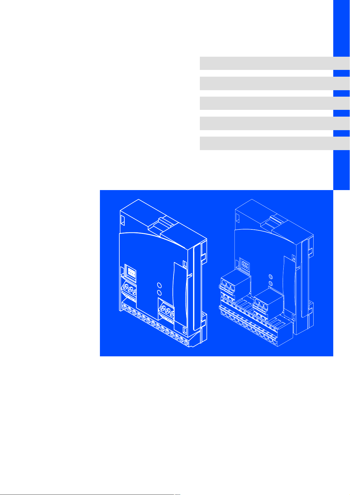
E82ZAFIC001 / E82ZAFIC010
Function module
l
Page 2

Contentsi
1 About this documentation 4 . . . . . . . . . . . . . . . . . . . . . . . . . . . . . . . . . . . . . . . . . . . . . . . . . .
1.1 Document history 5 . . . . . . . . . . . . . . . . . . . . . . . . . . . . . . . . . . . . . . . . . . . . . . . . . . . .
1.2 Conventions used 6 . . . . . . . . . . . . . . . . . . . . . . . . . . . . . . . . . . . . . . . . . . . . . . . . . . . .
1.3 Terminology used 6 . . . . . . . . . . . . . . . . . . . . . . . . . . . . . . . . . . . . . . . . . . . . . . . . . . . .
1.4 Notes used 7 . . . . . . . . . . . . . . . . . . . . . . . . . . . . . . . . . . . . . . . . . . . . . . . . . . . . . . . . . .
2 Safety instructions 8 . . . . . . . . . . . . . . . . . . . . . . . . . . . . . . . . . . . . . . . . . . . . . . . . . . . . . . . . .
2.1 General safety information 8 . . . . . . . . . . . . . . . . . . . . . . . . . . . . . . . . . . . . . . . . . . . .
2.2 Device− and application−specific safety instructions 9 . . . . . . . . . . . . . . . . . . . . . . . .
2.3 Residual hazards 9 . . . . . . . . . . . . . . . . . . . . . . . . . . . . . . . . . . . . . . . . . . . . . . . . . . . . .
3 Product description 10 . . . . . . . . . . . . . . . . . . . . . . . . . . . . . . . . . . . . . . . . . . . . . . . . . . . . . . . .
3.1 Application as directed 10 . . . . . . . . . . . . . . . . . . . . . . . . . . . . . . . . . . . . . . . . . . . . . . .
3.2 Identification 10 . . . . . . . . . . . . . . . . . . . . . . . . . . . . . . . . . . . . . . . . . . . . . . . . . . . . . . . .
3.3 Connections and interfaces 11 . . . . . . . . . . . . . . . . . . . . . . . . . . . . . . . . . . . . . . . . . . . .
4 Technical data 13 . . . . . . . . . . . . . . . . . . . . . . . . . . . . . . . . . . . . . . . . . . . . . . . . . . . . . . . . . . . .
4.1 General data 13 . . . . . . . . . . . . . . . . . . . . . . . . . . . . . . . . . . . . . . . . . . . . . . . . . . . . . . . .
4.2 Operating conditions 14 . . . . . . . . . . . . . . . . . . . . . . . . . . . . . . . . . . . . . . . . . . . . . . . . .
4.3 Protective insulation 14 . . . . . . . . . . . . . . . . . . . . . . . . . . . . . . . . . . . . . . . . . . . . . . . . . .
4.4 Connection terminals 15 . . . . . . . . . . . . . . . . . . . . . . . . . . . . . . . . . . . . . . . . . . . . . . . . .
4.5 Communication time 16 . . . . . . . . . . . . . . . . . . . . . . . . . . . . . . . . . . . . . . . . . . . . . . . . .
4.5.1 Cycle time 16 . . . . . . . . . . . . . . . . . . . . . . . . . . . . . . . . . . . . . . . . . . . . . . . . . . .
4.5.2 Processing time 8200vector / 8200 motec 16 . . . . . . . . . . . . . . . . . . . . . . .
4.6 Dimensions 17 . . . . . . . . . . . . . . . . . . . . . . . . . . . . . . . . . . . . . . . . . . . . . . . . . . . . . . . . .
5 Installation 18 . . . . . . . . . . . . . . . . . . . . . . . . . . . . . . . . . . . . . . . . . . . . . . . . . . . . . . . . . . . . . . .
5.1 Mechanical installation 18 . . . . . . . . . . . . . . . . . . . . . . . . . . . . . . . . . . . . . . . . . . . . . . .
5.2 Electrical installation 19 . . . . . . . . . . . . . . . . . . . . . . . . . . . . . . . . . . . . . . . . . . . . . . . . . .
5.2.1 Wiring according to EMC (CE−typical drive system) 19 . . . . . . . . . . . . . . . . .
5.2.2 Wiring with a host (master) 20 . . . . . . . . . . . . . . . . . . . . . . . . . . . . . . . . . . . .
5.2.3 Voltage supply 21 . . . . . . . . . . . . . . . . . . . . . . . . . . . . . . . . . . . . . . . . . . . . . .
5.2.4 Terminal assignment 23 . . . . . . . . . . . . . . . . . . . . . . . . . . . . . . . . . . . . . . . . .
5.2.5 Cable cross−sections and screw−tightening torques 24 . . . . . . . . . . . . . . . .
5.2.6 Use of plug connectors 25 . . . . . . . . . . . . . . . . . . . . . . . . . . . . . . . . . . . . . . . .
2
l
EDS82ZAFIC EN 2.0
Page 3

Contents i
6 Commissioning 26 . . . . . . . . . . . . . . . . . . . . . . . . . . . . . . . . . . . . . . . . . . . . . . . . . . . . . . . . . . .
6.1 Before switching on 26 . . . . . . . . . . . . . . . . . . . . . . . . . . . . . . . . . . . . . . . . . . . . . . . . . .
6.2 Commissioning steps 27 . . . . . . . . . . . . . . . . . . . . . . . . . . . . . . . . . . . . . . . . . . . . . . . . .
6.3 Configuring Host (master) 29 . . . . . . . . . . . . . . . . . . . . . . . . . . . . . . . . . . . . . . . . . . . .
6.4 Setting for last bus node 29 . . . . . . . . . . . . . . . . . . . . . . . . . . . . . . . . . . . . . . . . . . . . . . .
6.5 Defining the user data length 30 . . . . . . . . . . . . . . . . . . . . . . . . . . . . . . . . . . . . . . . . . .
6.6 Connecting the mains voltage 32 . . . . . . . . . . . . . . . . . . . . . . . . . . . . . . . . . . . . . . . . . .
7 Process data transfer 33 . . . . . . . . . . . . . . . . . . . . . . . . . . . . . . . . . . . . . . . . . . . . . . . . . . . . . . .
7.1 Lenze device control 34 . . . . . . . . . . . . . . . . . . . . . . . . . . . . . . . . . . . . . . . . . . . . . . . . .
7.1.1 Process data transfer 34 . . . . . . . . . . . . . . . . . . . . . . . . . . . . . . . . . . . . . . . . .
7.1.2 Process data signals for 8200 vector / 8200 motec 36 . . . . . . . . . . . . . . . . .
7.2 DRIVECOM control 42 . . . . . . . . . . . . . . . . . . . . . . . . . . . . . . . . . . . . . . . . . . . . . . . . . . . .
7.2.1 DRIVECOM state machine 42 . . . . . . . . . . . . . . . . . . . . . . . . . . . . . . . . . . . . . .
7.2.2 DRIVECOM control word 43 . . . . . . . . . . . . . . . . . . . . . . . . . . . . . . . . . . . . . . .
7.2.3 DRIVECOM status word 44 . . . . . . . . . . . . . . . . . . . . . . . . . . . . . . . . . . . . . . . .
7.2.4 Bit control commands 45 . . . . . . . . . . . . . . . . . . . . . . . . . . . . . . . . . . . . . . . . .
7.2.5 Status bits 46 . . . . . . . . . . . . . . . . . . . . . . . . . . . . . . . . . . . . . . . . . . . . . . . . . . .
8 Parameter data transfer 47 . . . . . . . . . . . . . . . . . . . . . . . . . . . . . . . . . . . . . . . . . . . . . . . . . . . .
8.1 Configure parameter data channel (PCP communication) 47 . . . . . . . . . . . . . . . . . . .
8.1.1 Parameter sets for 8200 vector controller 48 . . . . . . . . . . . . . . . . . . . . . . . . .
8.2 Initialise PCP communication 49 . . . . . . . . . . . . . . . . . . . . . . . . . . . . . . . . . . . . . . . . . .
8.2.1 CRL entries 49 . . . . . . . . . . . . . . . . . . . . . . . . . . . . . . . . . . . . . . . . . . . . . . . . . .
8.2.2 Available PCP services 49 . . . . . . . . . . . . . . . . . . . . . . . . . . . . . . . . . . . . . . . . .
9 Diagnostics 54 . . . . . . . . . . . . . . . . . . . . . . . . . . . . . . . . . . . . . . . . . . . . . . . . . . . . . . . . . . . . . . .
9.1 LED status displays 54 . . . . . . . . . . . . . . . . . . . . . . . . . . . . . . . . . . . . . . . . . . . . . . . . . .
9.2 Troubleshooting and fault elimination 55 . . . . . . . . . . . . . . . . . . . . . . . . . . . . . . . . . . .
10 Code table 56 . . . . . . . . . . . . . . . . . . . . . . . . . . . . . . . . . . . . . . . . . . . . . . . . . . . . . . . . . . . . . . . .
10.1 Communication−relevant Lenze codes 58 . . . . . . . . . . . . . . . . . . . . . . . . . . . . . . . . . . .
10.2 Monitoring 61 . . . . . . . . . . . . . . . . . . . . . . . . . . . . . . . . . . . . . . . . . . . . . . . . . . . . . . . . . .
10.3 Diagnostics 62 . . . . . . . . . . . . . . . . . . . . . . . . . . . . . . . . . . . . . . . . . . . . . . . . . . . . . . . . . .
10.4 Important controller codes 67 . . . . . . . . . . . . . . . . . . . . . . . . . . . . . . . . . . . . . . . . . . . . .
11 Index 68 . . . . . . . . . . . . . . . . . . . . . . . . . . . . . . . . . . . . . . . . . . . . . . . . . . . . . . . . . . . . . . . . . . . .
EDS82ZAFIC EN 2.0
l
3
Page 4

About this documentation1
0Fig. 0Tab. 0
1 About this documentation
Contents
This documentation exclusively contains descriptions of the INTERBUS function modules
E82ZAFIC001 and E82ZAFIC010.
) Note!
This documentation supplements the mounting instructions supplied with the
function/communication module and the documentation of the used
standard device.
The mounting instructions contain safety instructions which must be
observed!
ƒ The features and functions of the function module are described in detail.
ƒ Typical applications are explained by means of examples.
ƒ Moreover, this documentation contains the following:
– Safety instructions which must be observed.
– The essential technical data of the function module
– Information on versions of the Lenze standard devices to be used
– Notes on troubleshooting and fault elimination
The theoretical concepts are only explained to the level of detail required to understand
the function of the function module.
Depending on the software version of the controller and the version of the »Engineer«
software installed, the screenshots in this documentation may deviate from the
»Engineer« representation.
This documentation does not describe any software provided by other manufacturers. No
liability can be accepted for corresponding data provided in this documentation. For
information on how to use the software, please refer to the host system (master)
documents.
All brand names mentioned in this documentation are trademarks of their respective
owners.
Validity information
The information given in this documentation is valid for the following devices:
Function module Type designation From hardware version From software version
INTERBUS
4
E82ZAFIC001
E82ZAFIC010
l
4A 20
EDS82ZAFIC EN 2.0
Page 5

Target group
This documentation is intended for all persons who plan, install, commission and maintain
the networking and remote service of a machine.
I Tip!
Information and auxiliary devices around the Lenze products can be found in
the download area at
http://www.Lenze.com
1.1 Document history
Version Description
1.0 11/2002 TD06 First edition
2.0 02/2012 TD17 General revision
About this documentation
Document history
1
Your opinion is important to us!
These instructions were created to the best of our knowledge and belief to give you the
best possible support for handling our product.
If you have suggestions for improvement, please e−mail us to:
feedback−docu@Lenze.de
Thank you for your support.
Your Lenze documentation team
EDS82ZAFIC EN 2.0
l
5
Page 6

1
About this documentation
Conventions used
1.2 Conventions used
This documentation uses the following conventions to distinguish between different
types of information:
Type of information Identification Examples/notes
Spelling of numbers
Decimal separator
Decimal Standard notation For example: 1234
Hexadecimal 0x[0 ... 9, A ... F] For example: 0x60F4
Binary
l Nibble
Text
Program name » « PC software
Icons
Page reference ^ Reference to another page with additional
Point In general, the decimal point is used.
For instance: 1234.56
In quotation marks
Point
For example: ´100´
For example: ´0110.0100´
For example: »Engineer«, »Global Drive
Control« (GDC)
information
For instance: ^ 16 = see page 16
1.3 Terminology used
Term Meaning
INTERBUS Fieldbus system by PHOENIX CONTACT
Standard device
Controller
Master INTERBUS node which takes over the master function in the fieldbus system.
Slave INTERBUS node which represents a slave in the fieldbus system.
Code "Container" for one or several parameters used to parameterise or monitor the
Subcode If a code contains several parameters, they are stored in "subcodes".
POW Process output data word
PIW Process input data word
PCP Peripherals Communication Protocol
Lenze controllers the function module can be used with (8200 vector, 8200 motec).
controller.
In the documentation, the slash "/" is used to separate the code from the subcode
(e.g. "C00118/3").
6
l
EDS82ZAFIC EN 2.0
Page 7

1.4 Notes used
The following pictographs and signal words are used in this documentation to indicate
dangers and important information:
Safety instructions
Structure of safety instructions:
} Danger!
(characterises the type and severity of danger)
Note
(describes the danger and gives information about how to prevent dangerous
situations)
Pictograph and signal word Meaning
{ Danger!
} Danger!
( Stop!
About this documentation
Notes used
Danger of personal injury through dangerous electrical voltage.
Reference to an imminent danger that may result in death or
serious personal injury if the corresponding measures are not
taken.
Danger of personal injury through a general source of danger.
Reference to an imminent danger that may result in death or
serious personal injury if the corresponding measures are not
taken.
Danger of property damage.
Reference to a possible danger that may result in property
damage if the corresponding measures are not taken.
1
Application notes
Pictograph and signal word Meaning
) Note!
I Tip!
,
Important note to ensure troublefree operation
Useful tip for simple handling
Reference to another documentation
EDS82ZAFIC EN 2.0
l
7
Page 8

2
Safety instructions
General safety information
2 Safety instructions
) Note!
It is absolutely vital that the stated safety measures are implemented in order
to prevent serious injury to persons and damage to material assets.
Always keep this documentation to hand in the vicinity of the product during
operation.
2.1 General safety information
} Danger!
Disregarding the following basic safety measures may lead to severe personal
injury and damage to material assets!
ƒ Lenze drive and automation components ...
... must only be used for the intended purpose.
... must never be operated if damaged.
... must never be subjected to technical modifications.
... must never be operated unless completely assembled.
... must never be operated without the covers/guards.
... can − depending on their degree of protection − have live, movable or rotating parts
during or after operation. Surfaces can be hot.
ƒ All specifications of the corresponding enclosed documentation must be observed.
This is vital for a safe and trouble−free operation and for achieving the specified product
features.
The procedural notes and circuit details provided in this document are proposals which
the user must check for suitability for his application. The manufacturer does not
accept any liability for the suitability of the specified procedures and circuit proposals.
ƒ Only qualified skilled personnel are permitted to work with or on Lenze drive and
automation components.
According to IEC 60364 or CENELEC HD 384, these are persons ...
... who are familiar with the installation, assembly, commissioning and operation of
the product,
... possess the appropriate qualifications for their work,
... and are acquainted with and can apply all the accident prevent regulations, directives
and laws applicable at the place of use.
8
l
EDS82ZAFIC EN 2.0
Page 9

Device− and application−specific safety instructions
2.2 Device− and application−specific safety instructions
ƒ During operation, the function module must be firmly connected to the standard
device.
ƒ With external voltage supply, always use a separate power supply unit, safely
separated to EN 61800−5−1 ("SELV"/"PELV"), in every control cabinet.
ƒ Only use cables corresponding to the given specifications (¶ 20).
, Documentation for the standard device, control system, system/machine
All other measures prescribed in this documentation must also be
implemented. Observe the safety instructions and application notes stated in
the documentation.
2.3 Residual hazards
Safety instructions
2
Protection of persons
ƒ If the controllers are used on a phase earthed mains with a rated mains voltage
³ 400 V, protection against accidental contact is not ensured without implementing
external measures. (See chapter "4.3", ^ 14)
Device protection
ƒ The module contains electronic components that can be damaged or destroyed by
electrostatic discharge.
EDS82ZAFIC EN 2.0
l
9
Page 10
3
APPLICATION
010 / 3A22
Product description
Application as directed
3 Product description
3.1 Application as directed
The function module ...
ƒ is an accessory module for use in conjunction with the following Lenze standard
devices:
Product series Device name From hardware version
Frequency inverter
ƒ connects Lenze standard devices to the serial INTERBUS communication system.
ƒ is a device intended for use in industrial power systems.
Any other use shall be deemed inappropriate!
8200 vector Vx14
8200 motec Vx14
3.2 Identification
APPLICATION
010/ 3A22
Series
INTERBUS
Version
Variant
001: Coated version
010: PT version
Hardware version
Software version
L
Type
Id.-No.
Prod.-No.
Ser.-No.
E82AF000P0B201XX
E82ZAFX005
E82ZAF I C xxx xx xx
10
l
EDS82ZAFIC EN 2.0
Page 11
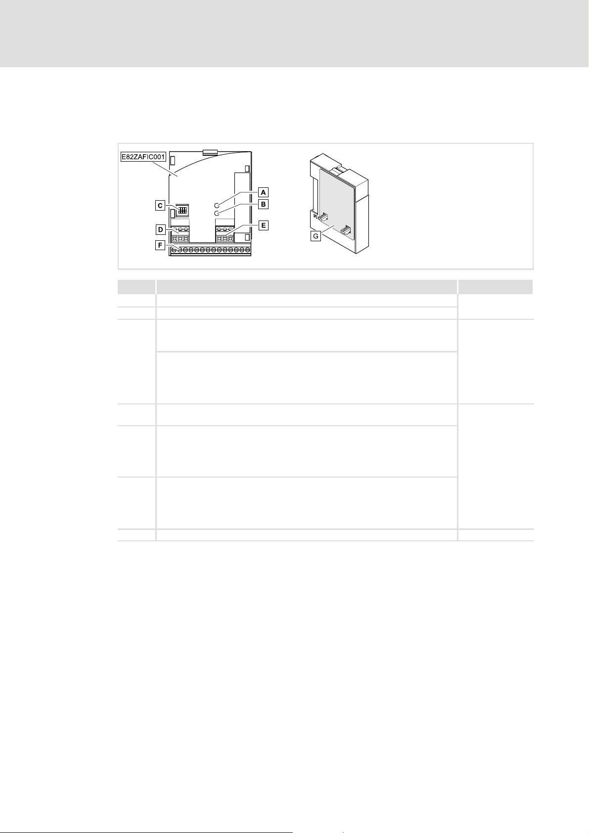
3.3 Connections and interfaces
E82ZAFIC001function module
Pos. Description See
A LED (yellow): Status of the INTERBUS communication
B LED (green): Connection status to the controller
C
D Plug connector X3.1
E Plug connector X3.2
F Plug connector X3.3
G Nameplate ^ 10
DIP switch S1
l Setting for the last node = OFF
l Setting for all other nodes = ON
DIP switches S2 ... S4
l Configuration of
– the process data words (PCD)
– the parameter data words (PCP)
– the ID codes
l Connection for external voltage supply of the function module
l Reference terminal GND1, e.g. for external voltage supply of the function
module
l Reference terminal GND2, e.g. for external supply of the controller inhibit
(CINH)
l Connection for
– INTERBUS
– controller inhibit (CINH)
– internal supply of the controller inhibit (CINH)
Product description
Connections and interfaces
^ 54
^ 29
^ 15
3
E82ZAFI004B
EDS82ZAFIC EN 2.0
l
11
Page 12
3
Product description
Connections and interfaces
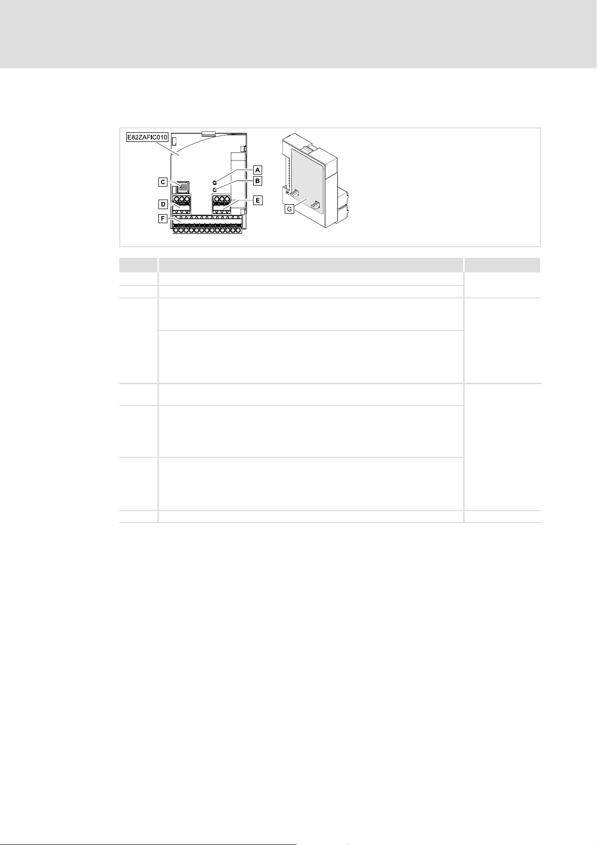
Function module E82ZAFIC010 (PT version)
Pos. Description See
A LED (yellow): Status of the INTERBUS communication
B LED (green): Connection status to the controller
C
D Plug connector X3.1
E Plug connector X3.2
F Plug connector X3.3
G Nameplate ^ 10
DIP switch S1
l Setting for the last node = OFF
l Setting for all other nodes = ON
DIP switches S2 ... S4
l Configuration of
– the process data words (PCD)
– the parameter data words (PCP)
– the ID codes
l Connection for external voltage supply of the function module
l Reference terminal GND1, e.g. for external voltage supply of the function
module
l Reference terminal GND2, e.g. for external supply of the controller inhibit
(CINH)
l Connection for
– INTERBUS
– controller inhibit (CINH)
– internal supply of the controller inhibit (CINH)
^ 54
^ 29
^ 15
E82ZAFI014B
12
l
EDS82ZAFIC EN 2.0
Page 13

4 Technical data
4.1 General data
Field Values
Order designation E82ZAFIC001 (coated)
Communication medium RS485
Network topology Ring (go and return line in the same cable)
Number of bus nodes Dependent on INTERBUS master (e.g. Phoenix Contact G4 master).
Distance between two bus nodes Max. 400 m
INTERBUS identification
(ID code)
Drive profile DRIVECOM profile "Drive technology 20"
INTERBUS node Slave
Baud rate 500 kbps
Process data words (PCD), 16 bits 1 ... 4 words
Parameter data words (PCP),
16 bits
PDU length Max. 64 bytes
Supported PCP services l Initiate
Communication time l Sum of the cycle time and the processing time in the bus nodes. The
Technical data
General data
E82ZAFIC010 (PT version)
For the following data, which depend on whether PCP communication is
used or not, always the smaller value applies:
l with PCP communication: max. 62 or
l without PCP communication: max. 256/number of PCDs
l With 1 word PCP: 227 (0xE3)
l Without PCP: 3 (0x03)
0 or 1 word
l Abort
l Status
l Identify
l Get−0V−long
l Read
l Write
times are independent of each other.
l Processing time in the standard device
– Parameter data (PCP): approx. 30 ms + 20 ms tolerance
– Process data (PCD): approx. 3 ms + 2 ms tolerance
4
EDS82ZAFIC EN 2.0
l
13
Page 14

4
Technical data
Operating conditions
4.2 Operating conditions
Ambient conditions
Climate
Storage
Transport IEC/EN 60721−3−2 2K3 (−25 to +70 °C)
Operation Corresponding to the data of the Lenze standard device used (see documentation
Pollution EN 61800−5−1 Degree of pollution 2
Degree of protection IP20 (protection against accidental contact according to NEMA 250 type 1)
4.3 Protective insulation
Insulation between incoming bus and ... Type of insulation (acc. to EN 61800−5−1)
l 8200 vector/motec power section Reinforced insulation
l Reference earth / PE Functional insulation
l Terminal X3.1/59 Functional insulation
l Terminal X3.3/20 Functional insulation
l Terminal X3.3/28 Functional insulation
IEC/EN 60721−3−1 1K3 (−25 to +60 °C)
of the standard device).
Insulation between incoming bus and ... Type of insulation (acc. to EN 61800−5−1)
Outgoing bus Functional insulation
Insulation between outgoing bus and ... Type of insulation (acc. to EN 61800−5−1)
l 8200 vector/motec power section Reinforced insulation
l Reference earth / PE Functional insulation
l Terminal X3.1/59 No electrical isolation
l Terminal X3.3/20 No electrical isolation
l Terminal X3.3/28 Functional insulation
14
l
EDS82ZAFIC EN 2.0
Page 15

Technical data
Connection terminals
4
4.4 Connection terminals
Terminal
X3.1/
59 External voltage supply of the function module
7 GND1 Reference potential for terminal X3.3/20
Terminal
X3.2/
7 GND1 Reference potential for terminal X3.3/20
39 GND2 Reference potential for controller inhibit (CINH) on terminal X3.3/28
Terminal
X3.3/
A /DO1
B DO1
C /DI1
D DI1
E GND3 Reference potential for incoming data line
F /DO2
G DO2
H /DI2
J DI2
K GND1 Reference potential for outgoing data line
+
28 CINH Controller inhibit
20 DC voltage source for internal supply of controller inhibit (CINH)
Designation Function / level
Designation Function / level
Designation Function / level
l U = 24 V DC (21.6 V − 0% ... 26.4 V + 0 %)
l Current consumption for 24 V DC: I = 90 mA
If the supply voltage is looped through to other bus nodes via terminal 59,
the current flowing must not exceed 3 A.
RS485 data line (incoming)
RS485 data line (outgoing)
Additional HF shield termination
l Input resistance: 3.3 kW
l Start = HIGH (+12 ... +30 V DC)
l Stop = LOW (0 ... +3 V DC)
l +20 V DC (reference: GND1)
l I
= 10 mA
max
EDS82ZAFIC EN 2.0
l
15
Page 16
4
Technical data
Communication time
Cycle time
4.5 Communication time
4.5.1 Cycle time
The cycle time of the communication system is the time required to exchange all process
data between the INTERBUS master and the nodes.
It depends on the data of the communication system and can be calculated e. g. for a baud
rate of 500 kbps as follows:
t
+ 3.35 @ 10*3(n ) 48 ) 3BK) ) 0.24L ) 0.2
zykl
t
cycl
n Sum of all data bits in the INTERBUS ring
BT Number of bus terminals
L Length of the remote bus cable [km]
Cycle time [ms]
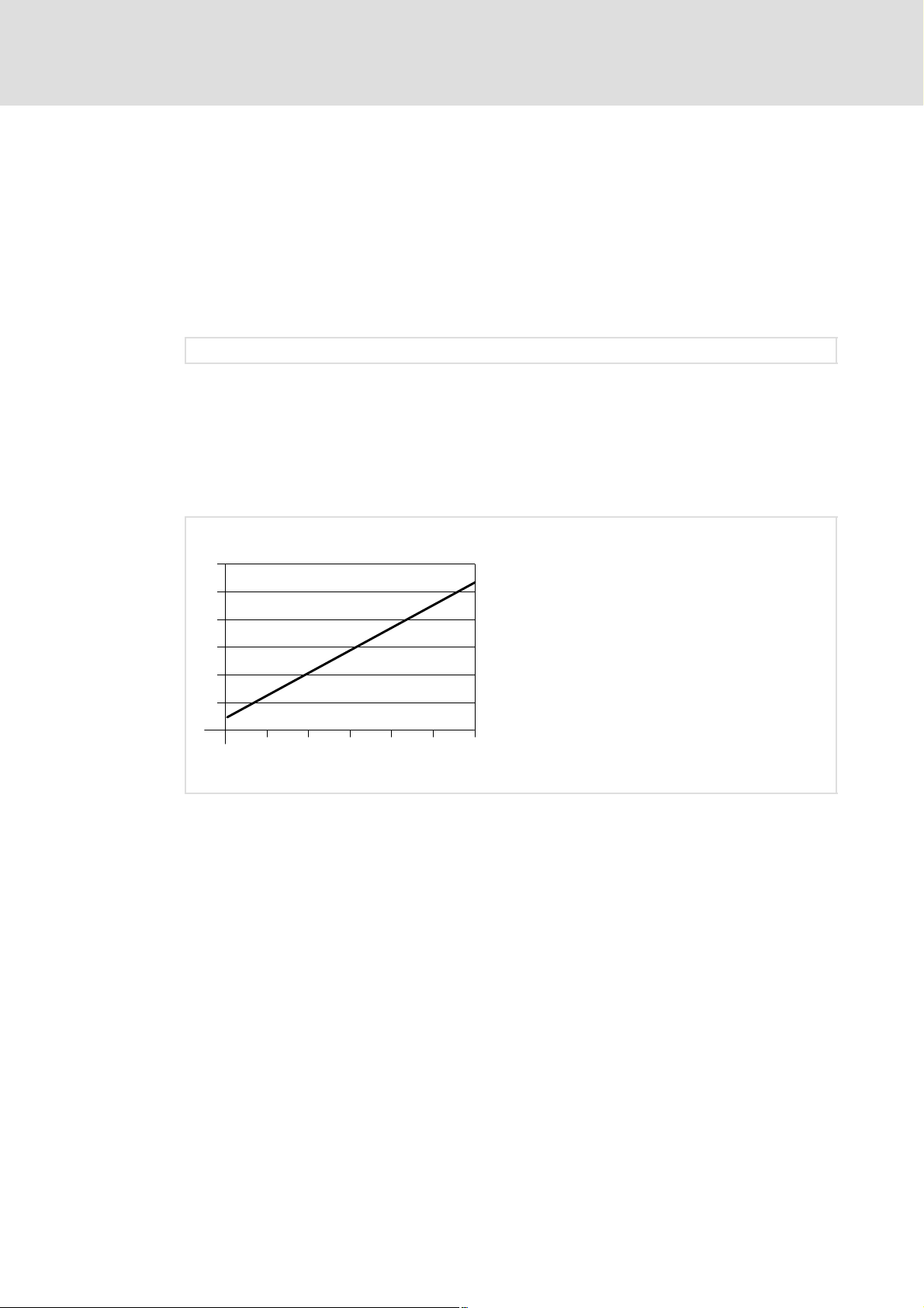
The following diagram shows the relationship between the cycle time and the number of
connected bus nodes. The given values refer to the connection of Lenze controllers
(e. g. 82xx) with 48 bits (1 parameter data word + 2 process data words.
Cycle time
[ms]
12
10
8
6
4
2
1
10
Number of bus nodes
Fig. 4−1 Relationship between cycle time and number of bus nodes
20
30 40
50 60
4.5.2 Processing time 8200vector / 8200 motec
The processing time in the controller is added to the INTERBUS transmission time or cycle
time.
There are no dependencies between parameter data and process data.
ƒ Parameter data (PCP): approx. 30 ms + 20 ms tolerance
ƒ Process data (PCD): approx. 3 ms + 2 ms tolerance
16
l
EDS82ZAFIC EN 2.0
Page 17
Technical data
Dimensions
Processing time 8200vector / 8200 motec
4
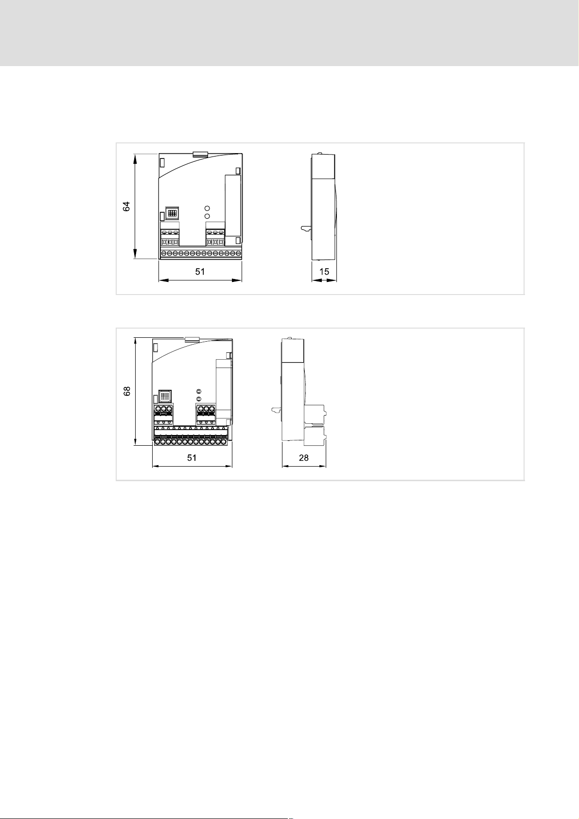
4.6 Dimensions
E82ZAFIC001function module
Function module E82ZAFIC010 (PT version)
E82ZAFI004B
E82ZAFI014B
EDS82ZAFIC EN 2.0
l
17
Page 18

5
Installation
Mechanical installation
5 Installation
} Danger!
Inappropriate handling of the function module and the standard device can
cause serious injuries to persons and damage to material assets.
Observe the safety instructions and residual hazards included in the
documentation of the standard device.
( Stop!
The device contains components that can be destroyed by electrostatic
discharge!
Before working on the device, the personnel must ensure that they are free of
electrostatic charge by using appropriate measures.
5.1 Mechanical installation
Follow the notes given in the Mounting Instructions for the standard device for the
mechanical installation of the function module.
The Mounting Instructions for the standard device ...
ƒ are part of the scope of supply and are enclosed with each device.
ƒ provide tips to avoid damage provide tips to avoid damage through improper
handling.
ƒ describe the obligatory order of installation steps.
18
l
EDS82ZAFIC EN 2.0
Page 19

Wiring according to EMC (CE−typical drive system)
5.2 Electrical installation
5.2.1 Wiring according to EMC (CE−typical drive system)
For wiring according to EMC requirements observe the following points:
) Note!
ƒ Separate control cables/data lines from motor cables.
ƒ Connect the shields of control cables/data lines at both ends in the case of
digital signals.
ƒ Use an equalizing conductor with a cross−section of at least 16mm
(reference:PE) to avoid potential differences between the bus nodes.
ƒ Observe the other notes concerning EMC−compliant wiring given in the
documentation for the standard device.
Wiring procedure
Installation
Electrical installation
5
2
1. Observe the bus topology, do not use any stubs.
2. Follow the wiring notes given in the documentation for the control system.
3. Only use cables which comply with the specifications listed (¶ 20).
4. Observe the notes concerning the voltage supply of the function module (¶ 21).
EDS82ZAFIC EN 2.0
l
19
Page 20
5
Installation
Electrical installation
Wiring with a host (master)
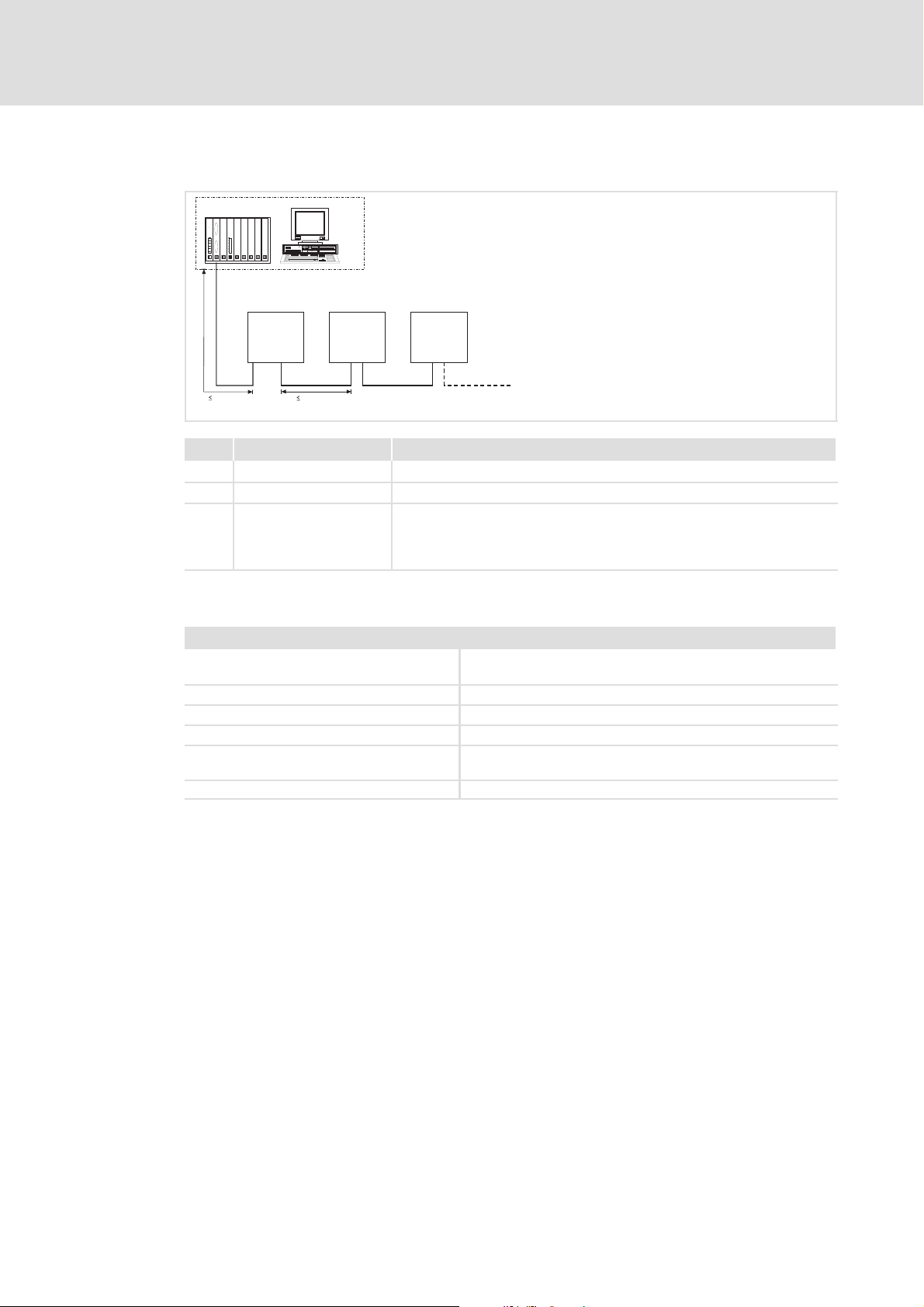
5.2.2 Wiring with a host (master)
1
3
GG
+
E82ZAFICxxx
222
400 m
400 m
No. Element Description
1 Host E.g. PC or PLC with INTERBUS master interface module
2 Bus cable Connects the INTERBUS master interface module to the function modules.
3 INTERBUS slave Applicable standard device (^ 10) with function module.
GG
+
E82ZAFICxxx
3
E82ZAFICxxx
l Set DIP switch S1 ( ^ 29):
GG
3
+
– Setting for the last node = OFF
– Setting for all other nodes = ON
E82ZAFI008
Specification of the transmission cable
General characteristics
Cable type Sold by the meter,
(e.g. PHOENIX CONTACT: IBS RBC Meter−T, Order No. 28 06 28 6)
Number of conductors 3 × 2, twisted pairs, with shared shield
Conductor cross−section > 0.2 mm
DC cable resistance < 96 W/km
Impedance (characteristic) l 120 W ± 20 % (f = 64 kHz)
l 100 W ±15 W (f > 1 MHz)
Capacitance per unit length < 60 nF/km (f = 800 Hz)
2
20
l
EDS82ZAFIC EN 2.0
Page 21

Installation
Electrical installation
Voltage supply
5
5.2.3 Voltage supply
Internal DC voltage supply
The internal voltage ...
ƒ supplies the controller inhibit (CINH).
ƒ is available at terminal X3.3/20.
External voltage supply
) Note!
Always use a separate power supply unit in every control cabinet and safely
separate it according to EN 61800−5−1 ("SELV"/"PELV") in the case of external
voltage supply and larger distances between the control cabinets.
External voltage supply of the communication module is required if communication via
the fieldbus is to be maintained even when the power supply of the standard device fails.
) Note!
With external voltage supply of the function module, the active bus
terminating resistor is fed independently of the operation of the standard
device. In this way, the bus system remains active even when the standard
device is switched off or fails.
EDS82ZAFIC EN 2.0
l
21
Page 22
5
Installation
Electrical installation
Voltage supply
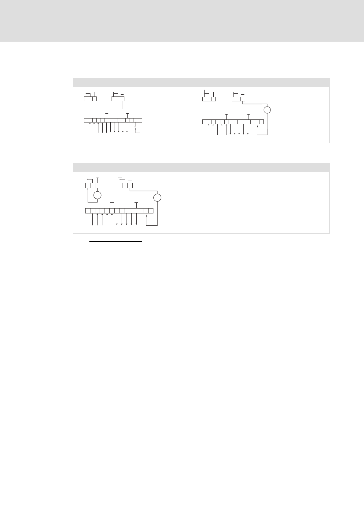
Supply of controller inhibit (CINH)
Supply via the internal voltage source (X3.3/20) Supply via the external voltage source
GND1
5959
X3.1
ABCDE FGHJ K ++ 28 20
X3.3
7
GND1
X3.2
GND3 GND1
GND2
77
39
+20V
E82ZAFI001 E82ZAFI002
GND1
7
5959
X3.1
ABCDE FGHJ K ++ 28 20
X3.3
Minimum wiring required for operation
Supply of function module and controller inhibit (CINH) via external voltage source
GND1
7
5959
X3.1
+
ABCDEFGHJK+ 28 20
X3.3
GND1
X3.2
_
+
GND3 GND1
GND2
39
77
_
+
+20V
GND1
GND2
39
77
X3.2
GND3 GND1
_
+
+20V
E82ZAFI003
Minimum wiring required for operation
22
l
EDS82ZAFIC EN 2.0
Page 23

Installation
Electrical installation
Terminal assignment
5
5.2.4 Terminal assignment
Terminal
X3.1/
59 External voltage supply of the function module
7 GND1 Reference potential for terminal X3.3/20
Terminal
X3.2/
7 GND1 Reference potential for terminal X3.3/20
39 GND2 Reference potential for controller inhibit (CINH) on terminal X3.3/28
Terminal
X3.3/
A /DO1
B DO1
C /DI1
D DI1
E GND3 Reference potential for incoming data line
F /DO2
G DO2
H /DI2
J DI2
K GND1 Reference potential for outgoing data line
+
28 CINH Controller inhibit
20 DC voltage source for internal supply of controller inhibit (CINH)
Designation Function / level
Designation Function / level
Designation Function / level
l U = 24 V DC (21.6 V − 0% ... 26.4 V + 0 %)
l Current consumption for 24 V DC: I = 90 mA
If the supply voltage is looped through to other bus nodes via terminal 59,
the current flowing must not exceed 3 A.
RS485 data line (incoming)
RS485 data line (outgoing)
Additional HF shield termination
l Input resistance: 3.3 kW
l Start = HIGH (+12 ... +30 V DC)
l Stop = LOW (0 ... +3 V DC)
l +20 V DC (reference: GND1)
l I
= 10 mA
max
EDS82ZAFIC EN 2.0
l
23
Page 24

5
Installation
Electrical installation
Cable cross−sections and screw−tightening torques
5.2.5 Cable cross−sections and screw−tightening torques
E82ZAFIC001function module
Range Values
Electrical connection Terminal strip with screw connection
Possible connections
Tightening torque 0.22 ... 0.25 Nm (1.9 ... 2.2 lb−in)
Bare end 5 mm
rigid:
flexible:
Function module E82ZAFIC010 (PT version)
Field Values
Electrical connection 2−pin plug connector with spring connection
Possible connections
rigid:
flexible:
Stripping length 9 mm
2
1.5 mm
without wire end ferrule
1.0 mm
with wire end ferrule, without plastic sleeve
0.5 mm
with wire end ferrule, with plastic sleeve
0.5 mm
1.5 mm
without wire end ferrule
1.5 mm
with wire end ferrule, without plastic sleeve
1.5 mm
with wire end ferrule, with plastic sleeve
1.5 mm
(AWG 16)
2
(AWG 18)
2
(AWG 20)
2
(AWG 20)
2
(AWG 16)
2
(AWG 16)
2
(AWG 16)
2
(AWG 16)
24
l
EDS82ZAFIC EN 2.0
Page 25

Installation
Electrical installation
Use of plug connectors
5
5.2.6 Use of plug connectors
( Stop!
Observe the following to prevent any damage to plug connectors and
contacts:
ƒ Only pug in / unplug the plug connectors when the controller is
disconnected from the mains.
ƒ Wire the plug connectors before plugging them in.
ƒ Unused plug connectors must also be plugged in.
Use of plug connectors with spring connection
E82ZAFX013
EDS82ZAFIC EN 2.0
l
25
Page 26

6
Commissioning
Before switching on
6 Commissioning
6.1 Before switching on
( Stop!
Before you switch on the standard device and the plugged−in function module
for the first time, check ...
ƒ the entire wiring for completeness, short circuit and earth fault.
ƒ the setting of the DIP switch S1 (¶ 29):
– Setting for the last node = OFF
– Setting for all other nodes = ON
26
l
EDS82ZAFIC EN 2.0
Page 27

6.2 Commissioning steps
) Note!
Do not change the setting sequence.
Step−by−step commissioning of the function module with the DRIVECOM device control is
described below.
Commissioning
Commissioning steps
6
Step Procedure Detailed
1. Configure the host (master) for communication via the function module. ^ 29
2. Inhibit the standard device via terminal 28 (CINH).
l Set terminal 28 to LOW level.
l Later on the standard device can be inhibited and enabled via the bus
system.
3. Set DIP switch S1:
l Setting for the last node = OFF
l Setting for all other nodes = ON
4. Define user data length via ...
l DIP switches S2 ... S4 or
l code C1515
5.
6.
7. If PCP communication is used, carry out the PCP service "initiate".
8. Select the function module as the source for control commands and
9.
10.
Connect the mains voltage and, if available, the separate voltage supply for
the function module.
l The standard device is ready for operation after approx. 1 second.
l Controller inhibit (CINH) is active.
Response
l The green LED "Connection status to standard device" at the front of the
function module is lit (only visible in the case of the 8200 vector).
l Keypad: dc(if attached)
It is now possible to communicate with the standard device, i.e. all codes can
be read and all writable codes can be adapted to the application.
Response
The yellow LED on the function module is blinking when the INTERBUS is
active.
l It is now possible to access the parameters of the standard device with
the PCP services "read" and "write".
setpoints.
l Set C0005 = 200.
– A preconfiguration for operation with the function module is carried
out.
– This preconfiguration already links the control words and status words.
Use C1511 to assign the process output data words (POW) of the master to
the process input data words of the standard device.
Lenze setting:
POW1: DRIVECOM control word (DRIVECOM CTRL)
POW2:
POW3:
POW4:
Use C1510 to assign the process output data words of the standard device to
the process input data words (PIW) of the master.
Lenze setting:
Setpoint1 (NSET1−N1)
Setpoint2 (NSET1−N2)
Additional setpoint (PCTRL1−NADD)
PIW1: DRIVECOM status word (DRIVECOM STAT)
PIW2:
Output frequency with slip (MCTRL1−NOUT+SLIP)
PIW3:
Output frequency without slip (MCTRL1−NOUT)
PIW4:
Apparent motor current (MCTRL1−IMOT)
information
Documentation for
the standard device
^ 29
^ 30
^ 32
^ 54
Documentation for
the standard device
^ 54
^ 50
INTERBUS
communication
manual
^ 59
INTERBUS
communication
manual
^ 58
EDS82ZAFIC EN 2.0
l
27
Page 28

6
Commissioning
Commissioning steps
ProcedureStep
11. Enable process output data with C1512 = 255.
Only required when C1511 has been changed.
12. Enable the standard device via terminal 28 (CINH).
l Set terminal 28 to HIGH level.
13. Select setpoint.
l The master transmits the setpoint via the selected process output data
word.
14. Change to the READY TO START state:
l The master transmits the DRIVECOM control word:
0000 0000 0111 1110
15. The standard device is in the READY TO START state.
l The master receives the DRIVECOM status word:
xxxx xxxx x01x 0001
16. Change to the OPERATION ENABLED state.
l The master transmits the DRIVECOM control word:
0000 0000 0111 1111
17. The drive starts up.
bin
bin.
bin
(007E
(007F
hex
hex
).
).
Detailed
information
INTERBUS
communication
manual
^ 42
28
l
EDS82ZAFIC EN 2.0
Page 29

6.3 Configuring Host (master)
For communication via the function module, first the host (master) must be configured.
Master settings
The configuration of the INTERBUS requires the device description file (EDS file) for the
communication module to be imported to the master configuration software.
The EDS file can be downloaded in the download area on http://www.Lenze.com.
6.4 Setting for last bus node
DIP switch 1
ON
Commissioning
Configuring Host (master)
6
1ON234
OFF
) Note!
ƒ DIP switch 1 must only be set to OFF for the last physical node.
ƒ Lenze setting: all switches OFF
Position Notes
OFF Standard device with function module is the last bus node
ON Standard device with function module is not the last bus node.
E82ZAFI009
EDS82ZAFIC EN 2.0
l
29
Page 30

6
Commissioning
Defining the user data length
6.5 Defining the user data length
The number of process data words (PCD) and parameter data words (PCP) can be set via
code C1515 or via the DIP switches S2 ... S4.
) Note!
ƒ Sum of all data words (PZD + PCP): max. 4 words
ƒ Switch off the voltage supply of the function module and the controller and
then on again to activate the changed settings.
Settings via DIP switches S2 ... S4
ON
1ON234
ƒ If one of the DIP switches S2 ... S4 is set to OFF, the configurations resulting from all
OFF
E82ZAFI009
switch positions are active at switch−on.
ƒ If the switch positions are invalid, the Lenze setting is activated:
– DIP switches S2 ... S4 = OFF (2 PCD words + 1 PCP word)
ƒ Code C1525 displays the current settings of the DIP switches S2 ... S4.
DIP switch
S2 S3 S4
OFF OFF OFF 0 2 1 227
ON OFF OFF 1 3 1 227
OFF OFF ON 4 2 0 3
ON OFF ON 5 4 0 3
ON ON ON Code C1515 active.
Value Number of process data
words (PCD)
Number of parameter
data words (PCP)
ID code
30
l
EDS82ZAFIC EN 2.0
Page 31

Defining the user data length
Settings via code
ƒ DIP switches S2 ... S4 = ON
ƒ Set the number of data words (PCD + PCP) via C1515.
Commissioning
6
Code
C1515
Subcode Lenze Values Access Data type
− 0
Values Description
0, 1, 4, 5 The configuration resulting from the values corresponding to the set DIP switch
11 ... 14 l No PCP
21 ... 23 l 1 word PCP
Name
Process/parameter data specification
0, 1, 4, 5
11 ... 14
21 ... 23
positions becomes active.
l 11 (1 word PCD) ... 14 (4 words PCD)
l 21 (1 word PCD) ... 23 (3 words PCD)
0x5A14 (23060)
Index
rw FIX32
EDS82ZAFIC EN 2.0
l
31
Page 32

6
6.6 Connecting the mains voltage
Commissioning
Connecting the mains voltage
) Note!
If the external voltage supply of the function module is used, switch it on as
well.
ƒ The standard device is ready for operation approx. 1 s after switching on the supply
voltage.
ƒ The controller inhibit is active.
ƒ The green LED at the front of the function module is lit.
Protection against uncontrolled start−up
) Note!
Establishing communication
For establishing communication via an externally supplied function module,
the standard device must be switched on as well.
ƒ After communication has been established, the externally supplied module
is independent of the power on/off state of the standard device.
Protection against uncontrolled start−up
After a fault (e.g. short−term mains failure), a restart of the drive is not always
wanted and − in some cases − even not allowed.
The restart behaviour of the controller can be set in C0142:
ƒ C0142 = 0 (Lenze setting)
– The controller remains inhibited (even if the fault is no longer active).
– The drive starts in a controlled mode by explicitly enabling the controller:
LOW−HIGH edge at terminal 28 (CINH)
ƒ C0142 = 1
– An uncontrolled restart of the drive is possible.
32
l
EDS82ZAFIC EN 2.0
Page 33

7 Process data transfer
INTERBUS transmits two different data types between the host (master) and the
controllers (slaves):
ƒ Parameter data
ƒ Process data
Process data
ƒ Process data is transmitted via the process data channel.
ƒ The process data serves to control the controller.
ƒ The host can directly access the process data. Data in the PLC, for instance, are
directly stored in the I/O area.
ƒ The data exchange between the master drive and the controller is required in the
shortest possible time. Here, small amounts of data can be transmitted cyclically.
Process data transfer 7
ƒ Process data ...
– are not saved in the controller;
– are transmitted between the host system and the controllers in order that a
constant exchange between current input and output data takes place.
ƒ Process data are, for instance, setpoints and actual values.
Parameter data
ƒ Parameter data is transmitted via the parameter data channel (PCP channel).
ƒ The transmission of parameter data is usually not time−critical.
ƒ Parameter data are, for instance, operating parameters, motor data and diagnostic
information.
ƒ The access to all Lenze codes and indices is permitted.
ƒ When saving parameter changes, please observe the notes regarding code C0003.
EDS82ZAFIC EN 2.0
l
33
Page 34

7
Process data transfer
Lenze device control
Process data transfer
7.1 Lenze device control
) Note!
Deactivate the DRIVECOM device control if you want to use the Lenze device
control.
For this purpose, use code C1510 / C1511.
7.1.1 Process data transfer
Process data telegrams between the host (master) and the controllers (slaves) connected
to the INTERBUS are distinguished as follows with regard to their direction:
ƒ Process data telegrams from the master
The master transmits max. 4process output data words (POW) to the slave.
ƒ Process data telegrams to the master
The master receives max. 4process input data words (PIW) from the slave.
Via the free configuration of the process data, assign the max. 4 process data words of the
INTERBUS to the process data words of the controller. The assignments can be defined in
the codes C1511 (process output data) ad C1510 (process input data).
Process data telegram to the master
The function block to be used for the cyclic process data telegram from the drive to the
master is called AIF−OUT.
The status word (byte 1 and byte 2) contained in the process data telegram is sent to the
master via the AIF−OUT function block.
Process data telegram from the master
The function block to be used for the cyclic process data telegram from the master to the
drive is called AIF−IN.
The control word (byte 1 and byte 2) contained in the process data telegram is sent from
the master and is received in the controller via the AIF−IN function block.
34
l
EDS82ZAFIC EN 2.0
Page 35

Process data transfer
Lenze device control
Process data transfer
Selection of setpoint source
8200 vector / 8200motec controller
For these controllers, the selection of the setpoint source is defined using code C0001
(index: 0x5FFE). For evaluating the process data, the code C0001 has to be set to the
value"3" when the controller is operated with the function module. The setpoint source is
provided by the process data channel which describes the frequency setpoint (mapping to
C0046) and the control word (C0135).
In C0412/x, the assignment of the setpoint source to the desired analog signal can be
checked/changed.
) Note!
The selection of the setpoint source (C0001) must be set identically in all
parameter sets used in the controller.
7
EDS82ZAFIC EN 2.0
l
35
Page 36

7
Process data transfer
Lenze device control
Process data signals for 8200 vector / 8200 motec
7.1.2 Process data signals for 8200 vector / 8200 motec
Configuring process output data
The assignment of the max. 4 process output data words (POW) of the master to bit control
commands or setpoints of the controller can be configured freely using C1511.
ƒ In order to activate the DRIVECOM device control, assign the DRIVECOM control
word to a POW (C1511/x = 17).
– The DRIVECOM control word is mapped to the FIF control word 1.
– The controller conforms to the DRIVECOM state machine (¶ 42).
ƒ The FIF control words can be used to set up an extended Lenze device control
(¶ 38).
) Note!
When C1511 is changed, the process output data is automatically locked to
ensure data consistency. Use C1512 to enable single or all POWs.
Configuration of the process output data
Code
C1511
Subcode Lenze Access Data type
1 POW1 17 DRIVECOM control word (DRIVECOM−CTRL) rw FIX32
2 POW2 3 Setpoint 1 (NSET1−N1) rw FIX32
3 POW3 4 Setpoint 2 (NSET1−N2) rw FIX32
4 PAW4 5 Additional setpoint (PCTRL1−NADD) rw FIX32
þ Parameter set transfer
Name
Configuring process output data
0x5A18 (23064)
Index
I Tip!
For a detailed description of the code, see ^ 59.
36
l
EDS82ZAFIC EN 2.0
Page 37

Process data transfer
Lenze device control
Process data signals for 8200 vector / 8200 motec
7
Master
INTERBUS
PAW 1
PAW 2
PAW 3
PAW 4
C1511/1
C1511/2
C1511/3
C1511/4
C1511/x = 17
C1511/x = 1
C1511/x = 2
C1511/x = 3
C1511/x = 4
C1511/x = 5
C1511/x = 6
C1511/x = 7
C1511/x = 9
C1511/x = 10
C1511/x = 11
C1511/x = 13
C1511/x = 14
C1511/x = 15
C1511/x = 16
DRIVECOM
CTRL
Byte 1
Byte 2
Byte 3
Byte 4
Byte 5, 6
Byte 7, 8
Byte 9, 10
Byte 11, 12
Byte 13, 14
Byte 15, 16
Byte 17, 18
Byte 19, 20
Byte 21, 22
Byte 23, 24
Byte 25, 26
Byte 27, 28
Byte 29, 30
Byte 31, 32
FIF-CTRL.B0
FIF-CTRL.B1
FIF-CTRL.B2
FIF-CTRL.B3
FIF-CTRL.B4
FIF-CTRL.B8
FIF-CTRL.B9
FIF-CTRL1
FIF-CTRL.B10
FIF-CTRL.B11
FIF-CTRL.B12
FIF-CTRL.B15
FIF-CTRL.B16
FIF-CTRL.B17
FIF-CTRL.B30
FIF-CTRL2
FIF-CTRL.B31
16 Bit
16 Bit
16 Bit
16 Bit
16 Bit
16 Bit
16 Bit
16 Bit
16 Bit
16 Bit
16 Bit
FIF-IN.W1
16 Bit
FIF-IN.W2
16 Bit
FIF-IN.W3
16 Bit
FIF-IN.W4
…
…
…
FIF-IN
DCTRL
QSP
DCTRL
CINH
TRIP-SET
TRIP-RESET
FIF-NSET1-N1
FIF-NSET1-N2
FIF-PCTRL1-NADD
FIF-PCTRL1-ACT
FIF-PCTRL1-SET1
FIF-RESERVED
FIF-MCTRL1-MSET
FIF-MCTRL1-VOLT-ADD
FIF-MCTRL1-PHI-ADD
FIF-RESERVED
FIF-IN.W1. B0 … FIF-IN.W1.B15
FIF-IN.W2. B0 … FIF-IN.W2.B15
FIF-IN.W1
FIF-IN.W2
FIF-IN.W3
FIF-IN.W4
C0410/x
200
C0412/x
200
C0415/x
C0417/x
C0418/x
C0419/x
C0421/x
Interne
Digitalsignale
Interne
Analogsignale
Digitalausgänge
Digitalsignale
auf Bus
Analogausgänge
Analogsignale
auf Bus
EDS82ZAFIC EN 2.0
Fig. 7−1 Free configuration of the 4 process output data words of the INTERBUS
l
E82ZAFI022/023
37
Page 38

7
Process data transfer
Lenze device control
Process data signals for 8200 vector / 8200 motec
FIF control word 1 (FIF−CTRL1) FIF control word 2 (FIF−CTRL2)
Bit Assignment Bit Assignment
0 / 1 JOG values (NSET1−JOG2/3 | NSET1−JOG1/3) 0 Manual/remote changeover (DCTRL1−H/Re)
Bit 1 0
0001C0046 active
1101JOG2 (C0038) active
JOG1 (C0037) active
JOG3 (C0039) active
2 Current direction of rotation (DCTRL1−CW/CCW) 2 Switch off process controller (PCTRL1−OFF)
01Not inverted
Inverted
3 Quick stop (QSP) (FIF−CTRL1−QSP)
01Not active
Active (deceleration via QSP ramp C0105)
4 Stop ramp function generator (NSET1−RFG1−STOP) 4 Stop process controller (PCTRL1−STOP)
01Not active
Active
5 Ramp function generator input = 0 (NSET1−RFG1−0) 5 CW rotation/quick stop (QSP) (DCTRL1−CW/QSP)
01Not active
Active (deceleration via C0013)
6 UP function of motor potentiometer (MPOT1−UP) 6 CCW rotation/quick stop (QSP) (DCTRL1−CCW/QSP)
01Not active
Active
7 DOWN function of motor potentiometer (MPOT1−DOWN) 7 X3/E1 is digital frequency input (DFIN1−ON)
01Not active
Active
8
Reserved
9 Controller inhibit (FIF−CTRL1−CINH) 9
01Controller enabled
Controller inhibited
10 External fault (FIF−CTRL1−TRIP−SET) 10
11 Reset fault (FIF−CTRL1−TRIP−RESET)
0 Þ 1 Bit change resets TRIP
12 / 13 Parameter set changeover
(DCTRL1−PAR3/4 | DCTRL1−PAR2/4)
Bit 13 12
0001PAR1
1101PAR3
PAR2
PAR4
14 DC injection brake (MTCRL1−DCB)
01Not active
Active
15
Reserved
Tab. 7−1 Parameter structure of FIF control word (FIF−CTRLx)
01Not active
Active
1 Switch off I−component of process controller
(PCTRL1−I−OFF)
01Not active
Active
01Not active
Active
3
Reserved
Do not write to this bit!
01Not active
Active
01Not active
Active
01Not active
Active
01Not active
Active
8
11
12
13
14
15
Reserved
Reserved
Reserved
Reserved
Reserved
Reserved
Reserved
Reserved
38
) Note!
Use of bit 5 and bit 6 in FIF control word 2
Set codes C0410/22 (DCTRL1−CW/QSP) and C0410/23 (DCTRL1−CCW/QSP) to
"200".
l
EDS82ZAFIC EN 2.0
Page 39

Process data transfer
Lenze device control
Process data signals for 8200 vector / 8200 motec
Configuring process input data
The assignment of the bit status information or actual values of the controller to the max.
4 process input data words (PIW) of the master can be configured freely:
ƒ In order to access DRIVECOM−compliant status information, assign the DRIVECOM
status word to a PIW (C1511/x = 18).
ƒ The FIF status word1 is mapped to the DRIVECOM status word.
Configuration of the process input data
7
Code
C1510
Subcode Lenze Access Data type
1 PIW1 18 DRIVECOM status word (DRIVECOM−STAT) rw FIX32
2 PIW2 3 Output frequency with slip (MCTRL1−NOUT+SLIP) rw FIX32
3 PIW3 4 Output frequency without slip (MCTRL1−NOUT) rw FIX32
4 PIW4 5 Apparent motor current (MCTRL1−IMOT) rw FIX32
þ Parameter set transfer
Name
Configuring process input data
0x5A19 (23065)
I Tip!
For a detailed description of the code, see ^ 58.
Index
EDS82ZAFIC EN 2.0
l
39
Page 40

7
Process data transfer
Lenze device control
Process data signals for 8200 vector / 8200 motec
MCTRL1-NOUT
MCTRL1-NOUT+SLIP
MCTRL1-IMOT
PCTRL1-ACT
PCTRL1-SET
PCTRL1-OUT
MCTRL1-MOUT
MCTRL1-DCVOLT
PCTRL1-RFG1-IN
FIF-STAT.B1
FIF-STAT.B2
…
FIF-STAT.B14
FIF-STAT.B15
FIF-STAT.B16
FIF-STAT.B17
…
FIF-STAT.B30
FIF-STAT.B31
16 Bit
16 Bit
16 Bit
16 Bit
16 Bit
16 Bit
16 Bit
16 Bit
16 Bit
FIF-OUT
DRIVECOM
FIF-STAT2FIF-STAT1
Byte 4Byte 2 Byte 3Byte1 Byte 9, 10 Byte 11, 12 Byte 13, 14 Byte 15, 16 Byte17, 18 Byte19, 20 Byte21, 22 Byte 23, 24
Byte 5, 6 Byte 7, 8
STAT
C1510/x = 18
C1510/x = 1
C1510/x = 2
C1510/x = 3
C1510/x = 4
C1510/x = 5
C1510/x = 6
C1510/x = 7
C1510/x = 8
C1510/x = 9
C1510/x = 10
C1510/x = 11
C1510/1
C1510/2
C1510/3
C1510/4
PEW1
PEW2
PEW3
PEW4
Master
INTERBUS
NSET1-NOUT
C0417/1
DCTRL1-IMP
C0417/3
C0417/4
C0417/5
C0417/6
DCTRL1-NOUT=0
DCTRL1-CINH
DCTRL1-STAT*1
DCTRL1-STAT*2
DCTRL1-STAT*4
DCTRL1-STAT*8
DCTRL1-OH-WARN
DCTRL1-OV
C0417/15
C0417/16
C0421/3
C0418/1
C0418/2
…
C0418/15
C0418/16
C0421/4
C0421/5
C0421/6
16 Bit
STAT1
STAT1.B0 FIF-OUT.W1.B0
FIF-OUT.W1.B1
STAT1.B1
STAT1.B2
STAT1.B3
STAT1.B4
STAT1.B5
STAT1.B6
STAT1.B7
STAT1.B8
STAT1.B9
STAT1.B10
STAT1.B11
STAT1.B12
STAT1.B13
STAT1.B14
STAT1.B15
FIF-OUT.W1.B14
FIF-OUT.W1.B15
16 Bit
STAT2
STAT2.B0 FIF-OUT.W2.B0
STAT2.B1 FIF-OUT.W2.B1
STAT2.B14 FIF-OUT.W2.B14
STAT2.B15 FIF-OUT.W2.B15
16 Bit
16 Bit
16 Bit
C1510/x = 12
FIF-OUT.W1
Byte 25, 26
…
FIF-OUT.W2
Byte 27, 28
…
FIF-OUT.W3 FIF-OUT.W4
Byte 29, 30 Byte 31, 32
C1510/x = 13
C1510/x = 14
C1510/x = 15
C1510/x = 16
E82ZAFI020/021
40
Fig. 7−11 Free configuration of the 4 process input data words of the INTERBUS
l
EDS82ZAFIC EN 2.0
Page 41

Process data transfer
Lenze device control
Process data signals for 8200 vector / 8200 motec
FIF status word 1 (FIF−STAT1) FIF status word 2 (FIF−STAT2)
Bit Assignment Bit Assignment
0 Current parameter set bit 0 (DCTRL1−PAR−B0) 0 Current parameter set bit 1 (DCTRL1−PAR−B1)
01Parameter set 1 or 3 active
Parameter set 2 or 4 active
1 Pulse inhibit (DCTRL1−IMP) 1 TRIP, Q
01Power outputs enabled
Power outputs inhibited
2 I
limit (MCTRL1−IMAX)
max
(If C0014 = 5: Torque setpoint)
01Not reached
Reached
3 Output frequency = frequency setpoint
(DCTRL1−RFG1=NOUT)
01False
True
4 Ramp function generator input 1 = ramp function
(NSET1−RFG1−I=O)
01False
5 Q
01Not reached
generator output 1
True
threshold (PCTRL1−QMIN) 5 C0054 < C0156 and NSET1−RFG1−I=O
min
Reached
6 Output frequency = 0 (DCTRL1−NOUT=0) 6 LP1 warning (fault in motor phase) active
01False
True
7 Controller inhibit (DCTRL1−CINH) 7 f < f
01Controller enabled
Controller inhibited
11...8 Device status (DCTRL1−STAT*1 ... STAT*8) 8 TRIP active (DCTRL1−TRIP)
Bit 11 10 9 8
00000100Controller initialisation
00011010Operation inhibited
0 1 0 1 DC−injection brake active
00111101Operation enabled
1 0 0 0 Fault active
1 1 1 1 Communication with basic device not
Switch−on inhibit
Flying−restart circuit active
Message active
possible
12 Overtemperature warning (DCTRL1−OH−WARN) 12
01No warning
− 10 °C reached
J
max
13 DC−bus overvoltage (DCTRL1−OV) 13
01No overvoltage
Overvoltage
14 Direction of rotation (DCTRL1−CCW) 14 C0054 > C0156 and NSET1−RFG1−I=0
01CW rotation
CCW rotation
15 Ready for operation (DCTRL1−RDY) 15
01Not ready for operation (fault)
Ready for operation (no fault)
Tab. 7−2 Parameter structure FIF status word (FIF−STATx)
01Parameter set 1 or 2 active
Parameter set 3 or 4 active
or pulse inhibit active (DCTRL1−TRIP−QMIN−IMP)
min
01False
True
2 PTC warning active (DCTRL1−PTC−WARN)
01False
True
3
Reserved
Do not write to this bit!
4 C0054 < C0156 and Q
(DCTRL1−(IMOT<ILIM)−QMIN)
01False
True
(DCTRL1−(IMOT<ILIM)−RFG−I=O)
01False
True
(DCTRL1−LP1−WARN)
01False
True
(NSET1−C0010 ... C0011)
min
01False
True
01False
True
threshold reached
min
9 Motor is running (DCTRL1−RUN)
01False
True
10 Motor is running clockwise (DCTRL1−RUN−CW)
01False
True
11 Motor is running counter−clockwise (DCTRL1−RUN−CCW)
01False
True
Reserved
Reserved
(DCTRL1−(IMOT>ILIM)−RFG−I=O)
01False
True
Reserved
7
EDS82ZAFIC EN 2.0
l
41
Page 42

7
Process data transfer
DRIVECOM control
DRIVECOM state machine
7.2 DRIVECOM control
7.2.1 DRIVECOM state machine
The control information is provided by the function module via the control word.
ƒ The controllers have standardised device states according to DRIVECOM Profile 20.
ƒ Information on the current device status is stored in the DRIVECOM parameter
"status word".
ƒ Commands in the DRIVECOM parameter "control word" can change the device
status. These commands are represented by arrows in the following diagram.
Switch on device
NOT READY TO SWITCH ON
Status word xxxx xxxx x0xx 0000
Automatically when
initialisation is
completed
SWITCH−ON INHIBIT
Status word xxxx xxxx x0xx 0000
9
Inhibit voltage
xxxx xxxx xxxx xx0x
READY TO SWITCH ON
Status word xxxx xxxx x01x 0001
8
Standstill
xxxx xxxx xxxx
x110
3
Switch on
xxxx xxxx xxxx x111
SWITCHED ON
Status word xxxx xxxx x01x 0011
2
Standstill
xxxx xxxx xxxx x110
FAULT REACTION ACTIVE
Status word xxxx xxxx x0xx 1111
FAULT
Status word xxxx xxxx x0xx 1000
Inhibit voltage
10
xxxx xxxx xxxx xx0x
7
Quick stop
xxxx xxxx xxxx x01x
6
Standstill
xxxx xxxx xxxx x110
13
Fault recognised
Automatically when
fault reaction is completed
14
Reset fault
xxxx xxxx 0xxx xxxx
xxxx xxxx 1xxx xxxx
12
Inhibit voltage
xxxx xxxx xxxx xx01
or
quick stop completed
42
45
Enable operation
xxxx xxxx xxxx 1111 and
act. speed value <> 0*
OPERATION ENABLED
Status word xxxx xxxx x01x 0111
Inhibit operation
xxxx xxxx xxxx 0111 or
act. speed value = 0 *
QUICK STOP ACTIVE
Status word xxxx xxxx x01x 0111
11
Quick stop
Inhibit RFG is mapped to
quick stop
xxxx xxxx xxxx x01x
Fig. 7−2 Status diagram of DRIVECOM device control
* only effective for 821X, 8200 vector when the automatic DC injection brake is active (C0106,
C2106 <> 0)
l
EDS82ZAFIC EN 2.0
Page 43

Process data transfer
DRIVECOM control
DRIVECOM control word
7
7.2.2 DRIVECOM control word
Bit Meaning
0 "Switch on" command
0 "Standstill" command active
1 "Switch on" command active
1 "Inhibit voltage" command
0 "Inhibit voltage" command active
1 "Inhibit voltage" command not active
2 "Quick stop (QSP)" command
0 "Quick stop (QSP)" command active
1 "Quick stop (QSP)" command not active
3 "Enable operation" command
0 "Inhibit operation" command active
1 "Enable operation" command active
4 "Inhibit RFG" command
Inhibits the ramp function generator (NSET1−RFG1). The quick stop function (QSP) is activated; the
device status of the drive does not change.
Mapping to FIF control word 1 (FIF−CTRL1), bit 3 negated (FIF−CTRL1−QSP)
0 "Inhibit RFG" active
1 "Inhibit RFG" not active
5 "RFG stop" command
Ramp function generator output (NSET1−RFG1) is "frozen"; the device status of the drive does not
change.
Mapping to FIF control word 1 (FIF−CTRL1), bit 4 negated (NSET1−RFG1−STOP)
0 "RFG stop" active
1 "RFG stop" not active
6 "RFG zero" command
Sets ramp function generator input (NSET1−RFG1) to 0. Þ Controlled deceleration via the ramp set
under C0013; the device status of the drive does not change.
Mapping to FIF control word 1 (FIF−CTRL1), bit 5 negated (NSET1−RFG1−0)
0 "RFG zero" active
1 "RFG zero" not active
7 TRIP reset
Resets fault (TRIP)
0 Þ 1 Bit change resets TRIP
8 DRIVECOM reserved
9 DRIVECOM reserved
10 DRIVECOM reserved
11 Mapping to FIF control word 1 (FIF−CTRL1), bit 10 (FIF−CTRL1−TRIP−SET)
12 Mapping to FIF control word 1 (FIF−CTRL1), bit 12 (DCTRL1−PAR2/4)
13 Mapping to FIF control word 1 (FIF−CTRL1), bit 13 (DCTRL1−PAR−3/4)
14 Mapping to FIF control word 1 (FIF−CTRL1), bit 14 (MCTRL1−DCB)
15 Not used
Tab. 7−3 Parameter structure of "DRIVECOM control word" (DRIVECOM−CTRL)
EDS82ZAFIC EN 2.0
l
43
Page 44

7
Process data transfer
DRIVECOM control
DRIVECOM status word
7.2.3 DRIVECOM status word
Bit Meaning
0 Device status "Ready to switch on"
01Status less than "Ready to switch on"
Status at least "Ready to switch on"
1 Device status "Switched on"
01Status less than "Switched on"
Status at least "Switched on"
2 Device status "Operation enabled"
01Status less than "Operation enabled"
Status "Operation enabled"
3 Device status "Fault"
01No fault (TRIP)
Fault (TRIP) active
4 Status "Inhibit voltage" command
01Command applied
Command not applied
5 Status "Quick stop (QSP)" command
01Command applied
Command not applied
6 Device status "Switch−on inhibit"
01Status "Switch−on inhibit" not active
Status "Switch−on inhibit" active
7 Collective warning
01No warning
Warning (overtemperature) active
8 Collective message
Automatic setting and resetting of pulse inhibit (IMP) in the device status "Operation enabled".
Possible causes: Undervoltage, overvoltage or overcurrent
01No message
Message IMP active
9 Bus access right
1 Always
10 Status speed/frequency deviation
01RFGon tu RFG
RFGon = RFG
11
12 Mapping of FIF status word 1 (FIF−STAT1), bit 0 (DCTRL1−PAR−B0)
13 Mapping of FIF status word 2 (FIFSTAT2), bit 0 (DCTRL1−PAR−B1)
14 Mapping of FIF status word 1 (FIFSTAT1), bit 2 (MCTRL1−IMAX)
15 Mapping of FIF status word 1 (FIF−STAT1), bit 5 (PCTRL1−QMIN)
Status DRIVECOM speed limitation
0
Always
off
off
44
l
EDS82ZAFIC EN 2.0
Page 45

7.2.4 Bit control commands
Process data transfer
DRIVECOM control
Bit control commands
7
Bit control commands
Command Meaning 7 6 5 4 3 2 1 0
Standstill From different device states ð "Ready to switch
Switch on
Enable operation Transition ð"Operation enabled"
Inhibit operation
Inhibit voltage Transition ð "Switch−on inhibit"
Quick stop (QSP)
Reset fault Reset fault
on"
Transition ð "Switched on" x x x x x 1 1 1
The controller inhibit (CINH) is deactivated.
Transition ð "Switched on"
The controller inhibit (CINH) is activated.
The controller inhibit (CINH) is activated.
Transition ð "Switch−on inhibit"
If the drive has been enabled ð controlled
deceleration via the quick stop ramp.
If the fault has been removed, automatically ð
"Switch−on inhibit".
Reset fault
RFG zero
RFG stop
Inhibit RFG
Enable operation
Quick stop (QSP)
Inhibit voltage
Switch on
The bit control commands of the control word depend on other bit
settings. The command is executed only for the following bit patterns:
Bits of the control word Note
x x x x x 1 1 0
x x x x 1 1 1 1
x x x x 0 1 1 1
x x x x x x 0 x
x x x x x 0 1 x
0ð1x x x x x x x
1: Bit set
0: Bit not
set
x: Any bit
status
EDS82ZAFIC EN 2.0
l
45
Page 46

7
Process data transfer
DRIVECOM control
Status bits
7.2.5 Status bits
Status bits
Device status Meaning 6 5 4 3 2 1 0
Not ready to switchonController is being initialised and is not yet ready
Switch−on inhibit
Ready to switch on Controller inhibited (CINH).
Switched on
Operation enabled Controller enabled (CINH).
Fault reaction active
Fault Controller is in the device status "Fault". 0 x x 1 0 0 0
Quick stop (QSP)
active
to operate.
After initialisation automatically ð "Ready to
switch on"
Controller inhibited (CINH).
Waiting for "Standstill" command
Waiting for "Switch−on" command
Controller inhibited (CINH).
Waiting for "Operation enabled" command.
Pulse inhibit can be set automatically
Fault (TRIP) recognised, a time−based,
fault−dependent reaction is executed.
Then automatically ð "Fault"
"Quick stop (QSP)" command has been sent in the
device status "Operation enabled" ð controlled
deceleration via the quick stop ramp.
After deceleration automatically ð "Switch−on
inhibit"
Switch−on inhibit
Quick stop (QSP)
Inhibit voltage
Fault
Operation enabled
Switched on
Ready to switch on
The current device status is unambiguously coded in the bits 0 ... 6 of
the status word:
Bits of the status word Note
0 x x 0 0 0 0
1 x x 0 0 0 0
0 1 x 0 0 0 1
0 1 x 0 0 1 1
0 1 x 0 1 1 1
0 x x 1 1 1 1
0 0 x 0 1 1 1
1 Bit set
0 Bit not
set
x Any bit
status
46
l
EDS82ZAFIC EN 2.0
Page 47

Parameter data transfer
Configure parameter data channel (PCP communication)
8 Parameter data transfer
8.1 Configure parameter data channel (PCP communication)
Access to the codes of the controller
The parameter data channel (PCP) ...
ƒ enables parameter setting and diagnostics of the controller;
ƒ permits access to Lenze parameters (codes);
ƒ is built up identically for both transfer directions.
The parameter data is addressed via codes that can be found listed in a code table in the
documentation of the controller.
The drive parameters to be changed are included in the Lenze controllers as codes.
The codes of the controller are addressed by the index while being accessed via the
function/communication module.
8
The index for Lenze code numbers is within 16576 (0x40C0) and 24575 (0x5FFF).
Conversion formula:
Index[dez] + 24575 * Lenze−Codestellennummer
Example for code C0001 (operating mode):
Decimal notation Hexadecimal notation
Index = 24575 − LENZE CODE NO Index
Index = 24574 (= 24575 − 1) Index
= 0x5FFF − LENZE CODE NO
hex
= 0x5FFE (= 0x5FFF − 1)
hex
hex
Value range of the Lenze parameters
The value range of the Lenze codes can be obtained from the "Code table" in the
documentation of the controller.
The data of the Lenze parameters is mainly represented in a fixed point format of
INTEGER32 data type with four decimal decimal positions. This means that the parameter
value from the documentation has to be multiplied by 10000.
Example for code C0039 (JOG) = 150.4 Hz
Parameter value multiplied by factor: 150.4 x 10000 =
ƒ 1504000 (decimal notation)
ƒ 0x0016F300 (hexadecimal notation)
EDS82ZAFIC EN 2.0
l
47
Page 48

8
Parameter data transfer
Configure parameter data channel (PCP communication)
Parameter sets for 8200 vector controller
8.1.1 Parameter sets for 8200 vector controller
The 8200 vector controller has four parameter sets the parameters of which can be directly
addressed via the INTERBUS.
Addressing
Addressing is carried out with a code offset:
ƒ Offset "0" addresses the parameter set 1 with the codes C0000 ... C1999.
ƒ Offset "2000" addresses the parameter set 2 with the codes C2000 ... C3999.
ƒ Offset "4000" addresses the parameter set 3 with the codes C4000 ... C5999.
ƒ Offset "6000" addresses the parameter set 4 with the codes C6000 ... C7999.
If a parameter is only available once (see documentation of the controller), use the code
offset "0".
Example
Addressing of the code C0011 (maximum field frequency) in different parameter sets:
ƒ C0011 in parameter set 1: Code no. = 11
ƒ C0011 in parameter set 2: Code no. = 2011
ƒ C0011 in parameter set 3: Code no. = 4011
ƒ C0011 in parameter set 4: Code no. = 6011
) Note!
Automatic saving of the changed parameter data is activated (Lenze basic
setting, can be switched off via C0003).
48
l
EDS82ZAFIC EN 2.0
Page 49

Parameter data transfer
Initialise PCP communication
CRL entries
8
8.2 Initialise PCP communication
8.2.1 CRL entries
In order that communication between the host (master) and the function/communication
module can take place, the following entries in the communication relation list (CRL) of the
master have to be set:
Field name Entry
Communication reference 2
Connection type Master/slave acyclic
Connection attribute Defined
Max−PDU Sending−High−Prio 0
Max−PDU Sending−Low−Prio 64
Max−PDU Receiving−High−Prio 0
Max−PDU Receiving−Low−Prio 64
Supported Services Request 0x803000
Supported Services Response 0x000000
Maximum SCC 1
Maximum RCC 1
Maximum SAC 1
Maximum RAC 1
8.2.2 Available PCP services
The PCP services (PCP = Peripherals Communication Protocol) serve to transmit
parameters via the PCP channel.
Lenze controllers support the following PCP services:
ƒ "Initiate": Establishing connection from the master to the controller (¶ 50)
ƒ "Abort": Aborting connection (¶ 50)
ƒ "Read": Reading parameters (¶ 51)
ƒ "Write": Writing parameters (¶ 51)
ƒ "Get−OD": Reading out the object directory (OD) (¶ 51)
ƒ "Identify": Identification of the controller (¶ 52)
ƒ "Status": Reading the status of the controller (¶ 53)
In the following, only those parameters and their contents are shown which are returned
by the Lenze controllers. All other transfer parameters of the given PCP services can be
obtained from the corresponding descriptions of the master.
EDS82ZAFIC EN 2.0
l
49
Page 50

8
Parameter data transfer
Initialise PCP communication
Available PCP services
Initiate
The "Initiate" PCP service establishes a logic connection between the master and the
function/communication module. The controller provides the following parameters:
Designation Value Meaning
Profile number 0x21 DRIVECOM profile of version 1
Password 0 Password function of INTERBUS is not supported.
Access groups 0 No access groups exist.
Access protection supported TRUE Access protection is supported.
OD version 0 Version of the object directory
Abort
The "Abort" PCP service aborts a logic connection between the master and the
function/communication module.
50
l
EDS82ZAFIC EN 2.0
Page 51

Parameter data transfer
Initialise PCP communication
Available PCP services
Read and Write
The "Read" PCP service reads parameters from the controller. The controller outputs the
requested parameter or an error message.
The "Write" PCP service writes on parameters of the controller. The controller outputs a
positive or negative feedback or an error message.
The following error messages can occur
Error class Error code Additional code Meaning
630x00 No access authorisation
6 5 0x10 Impermissible job parameter
6 5 0x11 Invalid subindex
6 5 0x12 Data length too big
6 5 0x13 Data length too small
6 6 0x00 Object is no parameter
6 7 0x00 Object does not exist
6 8 0x00 Data types do not comply with each other
8 0 0x00 Job cannot be executed
8 0 0x20 Job cannot be executed at the moment
8 0 0x21 Cannot be executed because of local control
8 0 0x22 Cannot be executed because of device status
8 0 0x30 Quit value range/parameter can only be changed if controller is
inhibited (CINH)
8 0 0x31 Value of the parameter too high
8 0 0x32 Value of the parameter too low
8 0 0x33 Sub parameter outside the value range
8 0 0x34 Value of the sub parameter too high
8 0 0x35 Value of the sub parameter too low
8 0 0x36 Maximum value is lower than minimum value
8 0 0x41 Communication object cannot be displayed on process data
8 0 0x42 Length of the process data exceeded
8 0 0x43 General collision with other values
8
EDS82ZAFIC EN 2.0
Get−OD
The "Get−OD" PCP service reads out the object description for every parameter and data
type.
l
51
Page 52

8
Parameter data transfer
Initialise PCP communication
Available PCP services
Identify
The "Identify" PCP service provides information on how to identify the controller. The
controller provides the following parameters:
Designation Value Meaning
Name of device
manufacturer
Device name Visible string with 15
Device version Visible string with 15
"Lenze" (as visible string) Company name
characters
characters
Device name for controller and
function/communication module
Software version of the device
Device name
Composition of the visible string:
ƒ Characters 1 ... 5: Name of the controller
– 4 characters of device name
– 1 space
ƒ Characters 6 ... 10: Name of the function/communication module
– 4 characters of device name
– 1 space
ƒ Characters 11 ... 15: No name
– 5 space
If no function/communication module is available, the corresponding area is filled with
spaces.
Example:
8200 vector controller with communication module EMF2113IB: "8212 2113 "
Visible string
Device name
Standard device
Device name
Module
Space
16
8212 2113
11 15
52
l
EDS82ZAFIC EN 2.0
Page 53

Parameter data transfer
Initialise PCP communication
Available PCP services
Device version
Composition of the visible string:
ƒ Characters 1 ... 5: Software version of the controller:
– 2 characters of basic version
– 2 characters of variant
– 1 character of version of variant
ƒ Characters 6 ... 10: Software version of the function/communication module
– 2 characters of basic version
– 2 characters of variant
– 1 character of version of variant
ƒ Characters 11 ... 15: No name
– 5 spaces
Example:
8200 vector controller (version V3.7; without variant and variant version) with
communication module (version V2.0; without variant and variant version):
"3700020000 "
8
Visible string
Device version
Standard device
Device version
Module
Space
16
3700 200000
11 15
Status
The "Status" PCP service provides status information on the controller. The controller
provides the following values:
Status Value Meaning
Logical status 0 = ready for communication Information on the current operating mode (C0001) of
Physical status l 0 = ready for operation
Operating status "OPERATION
ENABLED"
l 1 = partly ready for operation
all other device states
Local detail "Status word" parameter 24−bit value with:
the controller regarding communication
Information on the current operating status of the
controller.
(for device states, see ^ 42)
l Bit 0 ... 15: "Status word" profile parameter (index =
0x6041)
l Bit 16 ... 23: Value 0
EDS82ZAFIC EN 2.0
l
53
Page 54

9
Diagnostics
LED status displays
9 Diagnostics
9.1 LED status displays
LED
Pos. Colour Condition
A Yellow
B Green
E82ZAFIxxx, E82ZAFI014B
Description
Off No communication with the INTERBUS master.
Blinking Communication to the INTERBUS master via the function module is
On Internal error in the function module
Off
Blinking The function module is supplied with voltage but not connected to the
On The function module is supplied with voltage and is connected to the
established.
l The function module is not supplied with voltage.
l The standard device and/or the external voltage supply is/are
switched off.
standard device.
Causes:
l The standard device is switched off.
l The standard device is in the initialisation phase.
l The standard device is not available.
standard device.
54
l
EDS82ZAFIC EN 2.0
Page 55

Troubleshooting and fault elimination
9.2 Troubleshooting and fault elimination
The following faults can occur with controllers interconnected via the INTERBUS:
Fault Possible cause Remedy
INTERBUS master reports
bus error.
Drive cannot be enabled.
l Short circuit / open circuit Check INTERBUS ring circuit.
l The DIP switch has been set
incorrectly.
l No enable granted via the
control word.
l Controller inhibit (CINH) is still
active.
l No setpoint has been defined.
Diagnostics
Set DIP switch correctly.
Send 0x007F.
X3/28 = HIGH (+12 ... +30 V)
1. C0412/1 =200
INTERBUS must be set as setpoint
source.
2. Assign process output data in C1511 to
setpoint.
9
EDS82ZAFIC EN 2.0
l
55
Page 56

Codetabelle10
10 Code table
Overview
Code Subcode Index Designation See
C0002 − 0x5FFD
C1500 − 0x5A23
C1501 − 0x5A22
C1502 1 ... 4 0x5A21
C1503 1 ... 4 0x5A20
C1510 − 0x5A19
C1511 − 0x5A18
C1512 − 0x5A17
C1513 − 0x5A16
C1514 − 0x5A15
C1515 − 0x5A14
C1520 1 ... 10 0x5A0F
C1521 1 ... 10 0x5A0E
C1522 1 ... 16 0x5A0D
C1523 1 ... 16 0x5A0C
C1525 − 0x5A0A
C1530 − 0x5A05
C1531 1 ... 4 0x5A04
(24573)
(23075)
(23074)
(23073)
(23072)
(23065)
(23064)
(23063)
(23062)
(23061)
(23060)
(23055)
(23054)
(23053)
(23052)
(23050)
(23045)
(23044)
Parameter set management ^ 67
Software ID ^ 62
Software creation date ^ 62
Display of the software ID ^ 62
Display of the software creation date ^ 62
Configuring process input data ^ 58
Configuring process output data ^ 59
Enable process output data ^ 60
Response monitoring time of the PCD
communication
Monitoring response to PCD
communication fault
Process data specification ^ 60
Display of all words to the master ^ 63
Display of all words from the master ^ 63
Display of all process data words to the
standard device
Display of all process data words from
the standard device
Display of the current setting of the DIP
switches S2 ... S4
INTERBUS diagnostics ^ 66
Bus counter ^ 66
^ 61
^ 61
^ 64
^ 65
^ 65
56
l
EDS82ZAFIC EN 2.0
Page 57

How to read the code table
Column Meaning
Code
Subcode Subcode
Name Designation of the Lenze code
Index Index under which the parameter is addressed.
Lenze
Values
Access R = read access (reading permitted)
Data type l FIX32: 32−bit value with sign; decimal with 4 decimal positions
(Lenze) code
l The parameters of a configurable code marked with an asterisk (<Code>*) can only be accessed
via the communication module.
l The value of a configurable code marked with a double asterisk (<Code>**) is not transmitted
with the parameter set transfer.
Lenze setting of the code
g Display code
Configuration of this code is not possible.
Fixed values determined by Lenze (selection list) or a value range:
Minimum value [Smallest increment/unit] Maximum value
W = write access (writing permitted)
l U16: 2 bytes bit−coded
l U32: 4 bytes bit−coded
l VS: visible string, character string with defined length
Codetabelle 10
EDS82ZAFIC EN 2.0
l
57
Page 58

10
Codetabelle
Communication−relevant Lenze codes
10.1 Communication−relevant Lenze codes
C1510:
Configuring process input data
Code
C1510
Subcode Lenze Values Access Data type
1 PIW1 18
2 PIW2 3
3 PIW3 4
4 PIW 4 5
þ Parameter set transfer
Name
Configuring process input data
The assignment of the bit status information or actual values of the controller to the max.
4 process input data words (PIW) of the master can be configured freely.
) Note!
For reasons of compatibility, subcodes 5 and 6 can also be read and written
with modules from software version V3.0. However, this has no effect.
Selection Scaling
1 FIF status word 1 (FIF−STAT1) 16 bits
2 FIF status word 2 (FIF−STAT2) 16 bits
3 Output frequency with slip (MCTRL1−NOUT+SLIP) ±24000 º ±480 Hz
4 Output frequency without slip (MCTRL1−NOUT) ±24000 º ±480 Hz
5 Apparent motor current (MCTRL1−IMOT) 214 º 100 % rated device current
6 Actual process controller value (PCTRL1−ACT) ±24000 º ±480 Hz
7 Process controller setpoint (PCTRL1−SET) ±24000 º ±480 Hz
8 Process controller output (PCTRL1−OUT) ±24000 º ±480 Hz
9 Device utilisation (MCTRL1−MOUT) ±214 º ±100 % rated motor torque
10 DC−bus voltage (MCTRL1−DCVOLT) 16383 º 565 VDC at 400 V mains
11 Ramp function generator input (NSET1−RFG1−IN) ±24000 º ±480 Hz
12 Ramp function generator output (NSET1−NOUT) ±24000 º ±480 Hz
13 FIF−OUT.W1 16 bits or 0 ... 65535
14 FIF−OUT.W2 16 bits or 0 ... 65535
15 FIF−OUT.W3 0 ... 65535
16 FIF−OUT.W4 0 ... 65535
17 DRIVECOM control word (DRIVECOM−CTRL) 16 bits
18 DRIVECOM status word (DRIVECOM−STAT) 16 bits
0x5A19 (23065)
Index
see table below rw FIX32
16383 º 325 VDC at 230 V mains
58
l
EDS82ZAFIC EN 2.0
Page 59

C1511:
Configuring process output data
Codetabelle
Communication−relevant Lenze codes
10
Code
C1511
Subcode Lenze Values Access Data type
1 POW1 17
2 POW2 3
3 POW3 4
4 POW 4 5
þ Parameter set transfer
Name
Configuring process output data
see table below rw FIX32
0x5A18 (23064)
Index
The assignment of the max. 4 process output data words (POW) of the master to bit control
commands or setpoints of the controller can be configured freely using C1511.
) Note!
For reasons of compatibility, subcodes 5 and 6 can also be read and written
with modules from software version V3.0. However, this has no effect.
Selection Scaling
1 FIF control word 1 (FIF−CTRL1) 16 bits
2 FIF control word 2 (FIF−CTRL2) 16 bits
3 Setpoint 1 (NSET1−N1) ±24000 º ±480 Hz
4 Setpoint 2 (NSET1−N2) ±24000 º ±480 Hz
5 Additional setpoint (PCTRL1−NADD) ±24000 º ±480 Hz
6 Actual process controller value (PCTRL1−ACT) ±24000 º ±480 Hz
7 Process controller setpoint (PCTRL1−SET1) ±24000 º ±480 Hz
8 reserved
9 Torque setpoint / limit value (MCTRL1−MSET) 214 º 100 % rated motor torque
10 PWM voltage (MCTRL1−VOLT−ADD)
11 PWM angle (MCTRL1−PHI−ADD)
12 reserved
13 FIF−IN.W1 16 bits or 0 ... 65535
14 FIF−IN.W2 16 bits or 0 ... 65535
15 FIF−IN.W3 0 ... 65535
16 FIF−IN.W4 0 ... 65535
17 DRIVECOM control word (DRIVECOM−CTRL) 16 bits
(
Only for special applications. Modifications only
after consulting Lenze!
EDS82ZAFIC EN 2.0
l
59
Page 60

10
Codetabelle
Communication−relevant Lenze codes
C1512:
Enable process output data
Code
C1512
Subcode Lenze Values Access Data type
−11 [1] 255 rw FIX32
þ Parameter set transfer
Name
Enable process output data
0x5A17 (23063)
Index
When C1511 is changed, the process output data is automatically locked to ensure data
consistency.
C1512 serves to unlock single or all process output data words (POW) again.
The decimal value of the bit settings enables any combination of the process output data
words (POW).
ƒ 0 = Lock output word
ƒ 1 = Unlock output word
Valency of the bit settings
POW 4 POW 3 POW 2 POW 1
3
2
2
2
1
2
0
2
The value 16 (0x10) in code C1512 serves to enable all process output data.
C1515:
Process/parameter data specification
Code
C1515
Subcode Lenze Values Access Data type
−0
þ Parameter set transfer
Name
Process/parameter data specification
0, 1, 4, 5
11 ... 14
21 ... 23
0x5A14 (23060)
rw FIX32
This code serves to change the number of process and parameter data words:
Values Description
0, 1, 4, 5 The configuration resulting from the settings of the DIP switches S2 ... S4 is
11 ... 14 l No PCP
21 ... 23 l 1 word PCP
accepted according to the valency entered.
l 11 (1 word PCD) ... 14 (4 words PCD)
l 21 (1 word PCD) ... 23 (3 words PCD)
) Note!
ƒ The settings of this code only become active if the DIP switches S2 ... S4 are
set to ON (¶ .
ƒ Switch off the voltage supply of the function/communication module and
then on again to activate changed settings.
Index
60
l
EDS82ZAFIC EN 2.0
Page 61

Codetabelle
Monitoring
10
10.2 Monitoring
C1513:
Response monitoring time of the PCD communication
Code
C1513
Subcode Lenze Values Access Data type
− 65535 0 [1 ms] 65535 rw FIX32
þ Parameter set transfer
Monitoring starts with the arrival of the first telegram.
If there is no message from the master within the response monitoring time set, the
response set in C1514 is carried out.
) Note!
A change of monitoring will be effective immediately.
The value 65535 switches off the response monitoring time.
C1514:
Monitoring response to PCD communication fault
Name
Response monitoring time of the PCD communication
0x5A16 (23062)
Index
Code
C1514
Subcode Lenze Values Access Data type
−0
þ Parameter set transfer
Name
Monitoring response to PCD communication fault
0 No action
1 TRIP (trouble)
2 CINH (controller inhibit)
3 QSP (quick stop)
0x5A15 (23061)
rw
Index
FIX32
If there is no message from the master within the response monitoring time (configurable
in C1513), the response set in this code is carried out.
) Note!
A change of the monitoring response will be effective immediately.
EDS82ZAFIC EN 2.0
l
61
Page 62

10
Codetabelle
Diagnostics
10.3 Diagnostics
C1500:
Software identification code
Code
C1500
Subcode Lenze Values Access Data type
−
o Parameter set transfer
The code contains a string with a length of 14 bytes. The identification code is output, e.g.
’82ZAFI0C_xy000’.
C1501:
Software creation date
Code
C1501
Subcode Lenze Values Access Data type
−
o Parameter set transfer
The code contains a string with a length of 17 bytes. The creation date and time of the
software are output, e.g. ’Jun 21 2000 12:31’.
Name
Software ID
g
Name
Software creation date
g
− r VS
0x5A23 (23075)
Index
Index
0x5A22 (23074)
r VS
C1502:
Display of the software ID
Code
C1502
Subcode Lenze Values Access Data type
1 ... 4
o Parameter set transfer
Name
Display of the software ID
g
0x5A21 (23073)
r U32
Display of code C1500 in 4 subcodes with 4 characters each.
C1503:
Display of the software creation date
Code
C1503
Subcode Lenze Values Access Data type
1 ... 4
o Parameter set transfer
Name
Display of the software creation date
g
0x5A20 (23072)
r U32
Display of code C1501 in 4 subcodes with 4 characters each.
Index
Index
62
l
EDS82ZAFIC EN 2.0
Page 63

C1520:
Display of all words to the master
Codetabelle
Diagnostics
10
Code
C1520
Subcode Lenze Values Access Data type
1 PIW 1
2 PIW 2
3 PIW 3
4 PIW 4
o Parameter set transfer
Name
Display of all words to the master
g
0 [1] 65535 r U16
0x5A0F (23055)
Index
Display of the process input data words 1 ... 4 under the single subcodes. All words are
displayed, but only the configured ones are valid.
C1521:
Display of all words from the master
Code
C1521
Subcode Lenze Values Access Data type
1 POW1
2 POW2
3 POW3
4 POW4
o Parameter set transfer
Name
Display of all words from the master
g
0 [1] 65535 r U16
0x5A0E (23054)
Index
Display of the process output data words 1 ... 4 under the single subcodes. All words are
displayed, but only the configured ones are valid.
EDS82ZAFIC EN 2.0
l
63
Page 64

10
Codetabelle
Diagnostics
C1522:
Display of all process data words to the standard device
Code
C1522
Subcode Lenze Values Access Data type
1 ... 16
o Parameter set transfer
Name
Display of all process data words to the standard device
g
0 [1] 65535 r U16
0x5A0D (23053)
Index
Display of the process data output words 1 ... 16 that are transferred from the
function/communication module to the standard device:
Subcode Process data word
1 FIF control word 1 (FIF−CTRL1)
2 FIF control word 2 (FIF−CTRL2)
3 Setpoint 1 (NSET1−N1)
4 Setpoint 2 (NSET1−N2)
5 Additional setpoint (PCTRL1−NADD)
6 Actual process controller value (PCTRL1−ACT)
7 Process controller setpoint (PCTRL1−SET1)
8 reserved
9 Torque setpoint or torque limit (MCTRL1−MSET)
10 PWM voltage (MCTRL1−VOLT−ADD)
11 PWM angle (MCTRL1−PHI−ADD)
12 reserved
13 FIF−IN.W1
14 FIF−IN.W2
15 FIF−IN.W3
16 FIF−IN.W4
64
l
EDS82ZAFIC EN 2.0
Page 65

C1523:
Display of all process data words from the standard device
Codetabelle
Diagnostics
10
Code
C1523
Subcode Lenze Values Access Data type
1 ... 16
o Parameter set transfer
Name
Display of all process data words from the standard
device
g
0 [1] 65535 r U16
0x5A0C (23052)
Index
Display of the process data words 1 ... 16 that are transferred from the standard device to
the function/communication module:
Subcode Process data word
1 FIF status word 1 (FIF−STAT1)
2 FIF status word 2 (FIF−STAT2)
3 Output frequency with slip (MCTRL1−NOUT+SLIP)
4 Output frequency without slip (MCTRL1−NOUT)
5 Apparent motor current (MCTRL1−IMOT)
6 Actual process controller value (PCTRL1−ACT)
7 Process controller setpoint (PCTRL1−SET)
8 Process controller output (PCTRL1−OUT)
9 Device utilisation (MCTRL1−MOUT)
10 DC−bus voltage (MCTRL1−DCVOLT)
11 Ramp function generator input (NSET1−RFG1−IN)
12 Ramp function generator output (NSET1−NOUT)
13 FIF−OUT.W1
14 FIF−OUT.W2
15 FIF−OUT.W3
16 FIF−OUT.W4
C1525:
Display of the current DIP switch positions (S2 ... S4)
Code
C1525
Subcode Lenze Values Access Data type
−
o Parameter set transfer
Name
Display of the current DIP switch positions (S2 ... S4)
g
0 [1] 7 r FIX32
0x5A0A (23050)
Index
This code shows the current settings of the DIP switches S2 ... S4. These switches serve to
set the number of process and parameter data words (¶ 30).
DIP switch Value
S2 1
S3 2
S4 4
EDS82ZAFIC EN 2.0
l
65
Page 66

10
Codetabelle
Diagnostics
C1530:
INTERBUS diagnostics
Code
C1530
Subcode Lenze Values Access Data type
−
o Parameter set transfer
Name
Diagnostics
g
0x5A05 (23045)
0 00rFIX32
C1531:
Bus counter
Code
C1531
Subcode Lenze Values Access Data type
1 ... 4
o Parameter set transfer
Name
Bus counter
g
0x5A04 (23044)
0 [1] 65535 r FIX32
Dependent on the subcode, the following bus states are displayed:
ƒ Subcode 1: Data cycles per second
ƒ Subcode 2: Total data cycles
ƒ Subcode 3: Reserved (value is always ’0’)
ƒ Subcode 4: Reserved (value is always ’0’)
I Tip!
When the maximum count value ’65535’ has been reached, the counter
restarts at value ’0’.
Index
Index
66
l
EDS82ZAFIC EN 2.0
Page 67

Codetabelle
Important controller codes
10
10.4 Important controller codes
C0002:
Parameter set management
(extract)
Code
C0002
Subcode Lenze Values Access Data type
−0
þ Parameter set transfer
In the controller, up to 4 parameter sets (PAR1 ... PAR4) can be saved. In the
function/communication module, 1 parameter set (FPAR1) can be saved.
By means of parameter setting, the parameter set or sets can be defined in which the
delivery status is to be established.
Name
Parameter set management
0 Ready rw FIX32
1 Lenze setting ð PAR1 rw FIX32
2 Lenze setting ð PAR2 rw FIX32
3 Lenze setting ð PAR3 rw FIX32
4 Lenze setting ð PAR4 rw FIX32
31 Lenze setting ð FPAR1 rw FIX32
61 Lenze setting ð PAR1 + FPAR1 rw FIX32
62 Lenze setting ð PAR2 + FPAR1 rw FIX32
63 Lenze setting ð PAR3 + FPAR1 rw FIX32
64 Lenze setting ð PAR4 + FPAR1 rw FIX32
0x5FFD (24573)
Index
EDS82ZAFIC EN 2.0
l
67
Page 68

Index11
11 Index
A
Abort, 50
Ambient conditions, 14
− Climate, 14
Application as directed, 10
C
C0002: Parameter set management , 67
C1500: Software ID, 62
C1501: Software creation date , 62
C1502: Display of the software ID , 62
C1503: Display of the software creation date , 62
C1510: Configuring process input data , 58
C1511: Configuring process output data , 59
C1512: Enable process output data , 60
C1513: Response monitoring time of the PCD
communication, 61
C1514: Monitoring response to PCD communication fault,
61
C1515: Process/parameter data specification, 60
C1520: Display of all words to the master , 63
C1521: Display of all words from the master, 63
C1522: Display of all process data words, 64
C1523: Display of all process data words from the
standard device, 65
C1525: Display of the current DIP switch position (S2...S4),
65
C1530: INTERBUS diagnostics, 66
C1531: Bus counter, 66
Cable cross−sections, 24
Cable specification, 20
CE−typical drive system, 19
Code number, access via the fieldbus module, 47
Code number / Index, conversion, 47
Code table, 56
Codes, 58
− Lenze, 47
Commissioning, 26
− defining the user data length, 30
− setting for last bus node, 29
Commissioning steps, 27
Communication medium, 13
Communication Relation List (CRL), 49
Communication time, 13 , 16
Communication−relevant Lenze codes, 58
Configuration, Code table, 56
Connections, 11
Control, DRIVECOM, 42
control word, 35
Controller codes, 67
Conversion formula, Lenze codes, 47
CRL entries, 49
Cycle time, 16
D
Defining the user data length, 30
Definition of notes used, 7
Definitions, 6
Device control, Lenze, 34
Device protection, 9 , 18
Diagnostics, 54
DIP switch, S1 − setting for last node, 29
Drive profile, 13
DRIVECOM
− Bit control commands, 45
− Control word, 43
− State machine, 42
− Status bits, 46
− Status word, 44
DRIVECOM control, 42
E
Electrical installation, 19
External voltage supply, 21
F
Fault elimination, 55
Frequency setpoint, 35
G
Get−OD, 51
68
l
EDS82ZAFIC EN 2.0
Page 69

Index 11
I
ID code, 13
Identification, 10 , 52
Identify, 52
Index, conversion, 47
Initiate, 50
Installation, 18
− electrical, 19
− mechanical, 18
− Terminals, Assignment, 23
INTERBUS Cycle time, 16
INTERBUS identification, 13
Interfaces, 11
Internal DC voltage supply, 21
L
LED status displays, 54
Lenze codes, 47 , 58
− C0002, 67
− C1500, 62
− C1501, 62
− C1502, 62
− C1503, 62
− C1510, 58
− C1511, 59
− C1512, 60
− C1513, 61
− C1514, 61
− C1515, 60
− C1520, 63
− C1521, 63
− C1522, 64
− C1523, 65
− C1525, 65
− C1530, 66
− C1531, 66
− conversion formula, 47
Lenze data types, 47
M
Master, Settings, 29
Mechanical installation, 18
Monitoring, 61
N
Nameplate, 10
Nameplate data, 10
Network topology, 13
Notes, definition, 7
P
Parameter, C0142 (protection against unexpected
start−up), 32
parameter
− control word (C0135), 35
− frequency setpoint (C0046), 35
Parameter data channel, configure, 47
Parameter data transfer, 47
Parameter data words (PCP), 13
Parameter sets, 8200 vector, 48
PCP communication, initialise, 49
PCP services, 13 , 49
− abort, 50
− get−OD, 51
− identify, 52
− initiate, 50
− read and write, 51
− status, 53
PDU length, 13
Plug connectors, 25
− Use, spring connection, 25
Pollution, 14
Process data signals
− 8200 motec, 36
− 8200 vector, 36
Process data transfer, 33 , 34
process data words (PCD), 13
Process input data, configuring, 39
Processing time, 16
Processing time in the 8200 vector/motec, 16
Product description, 10
− application as directed, 10
PROFIBUS−DP function module, baud rate, 13
Protection against uncontrolled start−up, 32
Protection against unexpected start−up, 32
Protection of persons, 9
Protective insulation, 14
EDS82ZAFIC EN 2.0
l
69
Page 70

Index11
R
Read and Write, 51
Residual hazards, 9
S
Safety instructions, 8
− application as directed, 10
− definition, 7
− device− and application−specific, 9
− layout, 7
Screw−tightening torques, 24
Services, PCP, 49
Settings
− DIP switch, S1 − setting for last node, 29
− Master, 29
Specification of the transmission cable, 20
Status, 53
Status displays, 54
T
Technical data, 13
Terminals, Assignment, 23
Transmission cable, specification, 20
Troubleshooting, 55
Troubleshooting and fault elimination, Monitoring, 61
Type code, 10
− finding, 10
U
Usage conditions, Ambient conditions, Climate, 14
Use of plug connectors, 25
V
Validity of the documentation, 4
Value range, 47
Voltage supply, 21
− internal, 21
Voltage supply: external, 21
W
Wiring according to EMC, 19
Wiring with a host (master), 20
70
l
EDS82ZAFIC EN 2.0
Page 71

F
(
Ê
ü
© 02/2012
Lenze Drives GmbH
Postfach 10 13 52
D−31763 Hameln
Germany
+49(0)5154/ 82−0
+49(0)5154/ 82−28 00
Lenze@Lenze.de
www.Lenze.com
Service Lenze Service GmbH
Breslauer Straße 3
D−32699 Extertal
Germany
(
Ê
008000/ 2446877 (24 h helpline)
+49(0)5154/ 82−11 12
Service@Lenze.de
EDS82ZAFIC § .IDp § EN § 2.0 § TD17
10987654321
Q
 Loading...