

Page 1
EDK82ZAFIC−001
.MiQ
Ä.MiQä
Montageanleitung
Mounting Instructions
Instructions de montage
INTERBUS
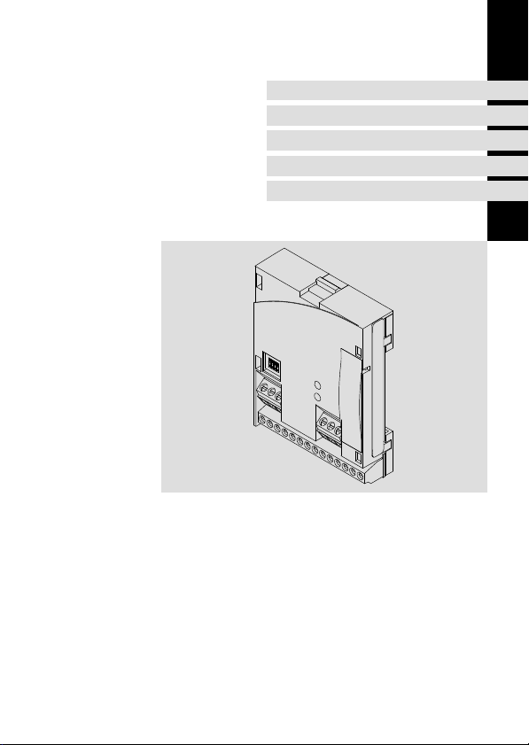
E82ZAFIC001
Funktionsmodul
Function module
Module de fonction
l
Page 2

, Lesen Sie zuerst diese Anleitung und die Dokumentation zum Grundgerät,
bevor Sie mit den Arbeiten beginnen!
Beachten Sie die enthaltenen Sicherheitshinweise.
, Please read these instructions and the documentation of the standard
device before you start working!
Observe the safety instructions given therein!
, Lire le présent fascicule et la documentation relative à l’appareil de base
avant toute manipulation de l’équipement !
Respecter les consignes de sécurité fournies.
Page 3
E82ZAFI004B
Page 4

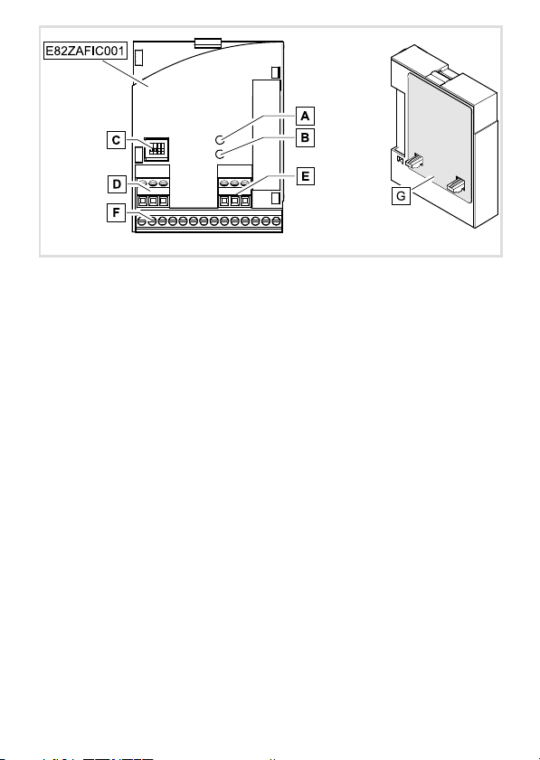
Legende zur Abbildung auf der Ausklappseite
Pos. Beschreibung Ausführliche
A LED (gelb): Status der INTERBUS−Kommunikation
B LED (grün): Verbindungsstatus zum Antriebsregler
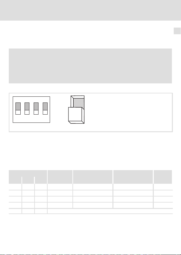
C
DIP−Schalter S1
l Einstellung für den letzten Busteilnehmer = OFF
l Einstellung für alle anderen Busteilnehmer = ON
DIP−Schalter S2 ... S4
l Konfiguration
– der Prozessdaten−Wörter (PZD)
– der Parameterdaten−Wörter (PCP)
D Steckerleiste X3.1
E Steckerleiste X3.2
F Steckerleiste X3.3
G Typenschild ^ 10
0Abb. 0Tab. 0
– des ID−Codes
l Anschluss für externe Spannungsversorgung des Funktionsmoduls
l Bezugsklemme GND1, z. B. für die externe Spannungsversorgung des
Funktionsmoduls
l Bezugsklemme GND2, z. B. für die externe Versorgung der Reglersperre
(CINH)
l Anschluss für
– INTERBUS
– Reglersperre (CINH)
– interne Versorgung der Reglersperre (CINH)
Information
^ 31
^ 29
^ 13
4
l
EDK82ZAFIC−001 DE/EN/FR 5.0
Page 5

Inhalt i
1 Über diese Dokumentation 6. . . . . . . . . . . . . . . . . . . . . . . . . . . . . . . . . . . . . . . . . . . .
2 Sicherheitshinweise 7. . . . . . . . . . . . . . . . . . . . . . . . . . . . . . . . . . . . . . . . . . . . . . . . . .
3 Produktbeschreibung 8. . . . . . . . . . . . . . . . . . . . . . . . . . . . . . . . . . . . . . . . . . . . . . . .
Funktion 8. . . . . . . . . . . . . . . . . . . . . . . . . . . . . . . . . . . . . . . . . . . . . . . . . . . . . . . . . . .
Bestimmungsgemäße Verwendung 8. . . . . . . . . . . . . . . . . . . . . . . . . . . . . . . . . . . .
Lieferumfang 9. . . . . . . . . . . . . . . . . . . . . . . . . . . . . . . . . . . . . . . . . . . . . . . . . . . . . . .
Identifikation 10. . . . . . . . . . . . . . . . . . . . . . . . . . . . . . . . . . . . . . . . . . . . . . . . . . . . . . .
4 Technische Daten 11. . . . . . . . . . . . . . . . . . . . . . . . . . . . . . . . . . . . . . . . . . . . . . . . . . . .
Allgemeine Daten 11. . . . . . . . . . . . . . . . . . . . . . . . . . . . . . . . . . . . . . . . . . . . . . . . . . .
Einsatzbedingungen 12. . . . . . . . . . . . . . . . . . . . . . . . . . . . . . . . . . . . . . . . . . . . . . . . .
Schutzisolierung 12. . . . . . . . . . . . . . . . . . . . . . . . . . . . . . . . . . . . . . . . . . . . . . . . . . . . .
Daten der Anschlussklemmen 13. . . . . . . . . . . . . . . . . . . . . . . . . . . . . . . . . . . . . . . . .
Abmessungen 14. . . . . . . . . . . . . . . . . . . . . . . . . . . . . . . . . . . . . . . . . . . . . . . . . . . . . . .
5 Mechanische Installation 15. . . . . . . . . . . . . . . . . . . . . . . . . . . . . . . . . . . . . . . . . . . . .
6 Elektrische Installation 16. . . . . . . . . . . . . . . . . . . . . . . . . . . . . . . . . . . . . . . . . . . . . . .
EMV−gerechte Verdrahtung 16. . . . . . . . . . . . . . . . . . . . . . . . . . . . . . . . . . . . . . . . . . .
Verdrahtung mit einem Leitrechner 17. . . . . . . . . . . . . . . . . . . . . . . . . . . . . . . . . . . .
Spannungsversorgung 19. . . . . . . . . . . . . . . . . . . . . . . . . . . . . . . . . . . . . . . . . . . . . . .
Belegung der Anschlussklemmen 21. . . . . . . . . . . . . . . . . . . . . . . . . . . . . . . . . . . . . .
Leitungsquerschnitte und Schraubenanzugsmomente 22. . . . . . . . . . . . . . . . . . . . .
7 Inbetriebnahme 23. . . . . . . . . . . . . . . . . . . . . . . . . . . . . . . . . . . . . . . . . . . . . . . . . . . . .
Vor dem ersten Einschalten 23. . . . . . . . . . . . . . . . . . . . . . . . . . . . . . . . . . . . . . . . . . .
Inbetriebnahmeschritte 24. . . . . . . . . . . . . . . . . . . . . . . . . . . . . . . . . . . . . . . . . . . . . .
Leitsystem (Master) konfigurieren 26. . . . . . . . . . . . . . . . . . . . . . . . . . . . . . . . . . . . .
Nutzdatenlänge festlegen 27. . . . . . . . . . . . . . . . . . . . . . . . . . . . . . . . . . . . . . . . . . . .
Einstellung für letzten Busteilnehmer 29. . . . . . . . . . . . . . . . . . . . . . . . . . . . . . . . . . .
Netzspannung zuschalten 30. . . . . . . . . . . . . . . . . . . . . . . . . . . . . . . . . . . . . . . . . . . .
8 Diagnose 31. . . . . . . . . . . . . . . . . . . . . . . . . . . . . . . . . . . . . . . . . . . . . . . . . . . . . . . . . . .
LED−Statusanzeigen 31. . . . . . . . . . . . . . . . . . . . . . . . . . . . . . . . . . . . . . . . . . . . . . . . . .
EDK82ZAFIC−001 DE/EN/FR 5.0
l
5
Page 6

1 Über diese Dokumentation
1 Über diese Dokumentation
Inhalt
Diese Dokumentation enthält ...
ƒ Sicherheitshinweise, die Sie unbedingt beachten müssen;
ƒ Angaben über Versionsstände der zu verwendenden Lenze Grundgeräte;
ƒ Informationen zur mechanischen und elektrischen Installation des Funktionsmoduls;
ƒ Informationen zur Inbetriebnahme des Funktionsmoduls;
ƒ Technische Daten.
Informationen zur Gültigkeit
Die Informationen in dieser Dokumentation sind gültig für folgende Geräte:
Funktionsmodul Typenbezeichnung ab Hardwarestand ab Softwarestand
INTERBUS E82ZAFIC001 4A 20
Zielgruppe
Diese Dokumentation wendet sich an Personen, die das beschriebene Produkt nach Projektvorgabe installieren und in Betrieb nehmen.
I Tipp!
Informationen und Hilfsmittel rund um die Lenze−Produkte finden Sie im
Download−Bereich unter
http://www.Lenze.com
6
l
EDK82ZAFIC−001 DE/EN/FR 5.0
Page 7

Sicherheitshinweise 2
2 Sicherheitshinweise
} Gefahr!
Unsachgemäßer Umgang mit dem Funktionsmodul und dem Grundgerät kann
schwere Personenschäden und Sachschäden verursachen.
Beachten Sie die in der Dokumentation zum Grundgerät enthaltenen
Sicherheitshinweise und Restgefahren.
( Stop!
Elektrostatische Entladung
Durch elektrostatische Entladung können elektronische Bauteile innerhalb des
Funkionsmoduls beschädigt oder zerstört werden.
Mögliche Folgen:
ƒ Das Funktionsmodul ist defekt.
ƒ Die Feldbus−Kommunikation ist nicht möglich oder fehlerhaft.
Schutzmaßnahmen
ƒ Befreien Sie sich vor dem Berühren des Moduls von elektrostatischen
Aufladungen.
EDK82ZAFIC−001 DE/EN/FR 5.0
l
7
Page 8

3 Produktbeschreibung
Funktion
3 Produktbeschreibung
Funktion
Das Funktionsmodul koppelt das Grundgerät an das Kommunikationssystem INTERBUS.
Bestimmungsgemäße Verwendung
Das Funktionsmodul ...
ƒ ist eine Zubehör−Baugruppe, die mit folgenden Lenze−Grundgeräten eingesetzt
werden kann:
Produktreihe Gerätebezeichnung ab Hardwarestand
Frequenzumrichter
ƒ koppelt Lenze−Grundgeräte an das serielle Kommunikationssystem INTERBUS.
ƒ ist ein Betriebsmittel zum Einsatz in industriellen Starkstromanlagen.
Jede andere Verwendung gilt als sachwidrig!
8200 vector Vx14
8200 motec Vx14
I Tipp!
Weiterführende Informationen zu diesem Funktionsmodul finden Sie im
entsprechenden Kommunikationshandbuch.
Die PDF−Datei finden Sie im Download−Bereich unter:
http://www.Lenze.com
8
l
EDK82ZAFIC−001 DE/EN/FR 5.0
Page 9
Lieferumfang
Produktbeschreibung
Lieferumfang
7
8
3
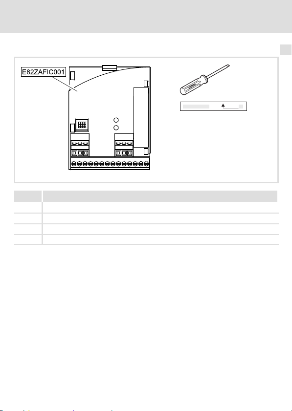
Pos. Lieferumfang
Funktionsmodul E82ZAFIC001
Montageanleitung
Schraubendreher
7
Klebestreifen
8
EDK82ZAFIC−001 DE/EN/FR 5.0
l
E82ZAFI007/E82ZAFI004B
9
Page 10
3 Produktbeschreibung
APPLICATION
010 / 3A22
Identifikation
Identifikation
APPLICATION
010/ 3A22
L
Type
Id.-No.
Prod.-No.
Ser.-No.
E82AF000P0B201XX
Produktreihe
INTERBUS
Gerätegeneration
Variante 001: Verlackte Ausführung
Hardwarestand
Softwarestand
E82ZAFX005
E82ZAF I C 001 4A 20
10
l
EDK82ZAFIC−001 DE/EN/FR 5.0
Page 11

Technische Daten
Allgemeine Daten
4 Technische Daten
Allgemeine Daten
Bereich Werte
Bestell−Bezeichnung E82ZAFIC001
Kommunikationsmedium RS485
Netzwerk−Topologie Ring (Hin− und Rückleitung im selben Kabel)
Anzahl Teilnehmer Abhängig vom INTERBUS−Master (z. B. Phoenix Contact G4−Master).
Entfernung zwischen zwei
Teilnehmern
INTERBUS−Kennung
(ID−Code)
Antriebs−Profil DRIVECOM−Profil "Antriebstechnik 20"
INTERBUS−Teilnehmer Slave
Übertragungsrate 500 kBit/s
Prozessdaten−Wörter (PZD),
16 Bits
Parameterdaten−Wörter (PCP),
16 Bits
PDU−Länge Maximal 64 Bytes
Unterstützte PCP−Dienste
Kommunikationszeit
Für folgende Angaben gilt in Abhängigkeit mit/ohne PCP−Kommunikation der jeweils kleinere Wert:
l mit PCP−Kommunikation: maximal 62 oder
l ohne PCP−Kommunikation: maximal 256/Anzahl PZD
Maximal 400 m
l mit 1 Wort PCP: 227 (0xE3)
l ohne PCP: 3 (0x03)
1 ... 4 Wörter
0 oder 1 Wörter
l Initiate
l Abort
l Status
l Identify
l Get−0V−long
l Read
l Write
l Summe aus der Zykluszeit und der Bearbeitungszeit in den Feld-
busteilnehmern. Die Zeiten sind unabhängig voneinander.
l Bearbeitungszeit im Grundgerät
– Parameterdaten (PCP): ca. 30 ms + 20 ms Toleranz
– Prozessdaten (PZD): ca. 3 ms + 2 ms Toleranz
4
EDK82ZAFIC−001 DE/EN/FR 5.0
l
11
Page 12

4 Technische Daten
Einsatzbedingungen
Einsatzbedingungen
Umgebungsbedingungen
Klimatisch
Lagerung
Transport IEC/EN 60721−3−2 2K3 (−25 ... +70 °C)
Betrieb Entsprechend der Daten des verwendeten Lenze Grundgerätes (siehe
Verschmutzung EN 61800−5−1 Verschmutzungsgrad 2
Schutzart IP20 (Berührschutz nach NEMA 250 Typ 1)
Schutzisolierung
Isolierung zwischen ankommenden Bus und ... Art der Isolierung (nach EN 61800−5−1)
l Leistungsteil 8200 vector/motec
l Bezugserde/PE
l Klemme X3.1/59
l Klemme X3.3/20
l Klemme X3.3/28
Isolierung zwischen ankommenden Bus und ... Art der Isolierung (nach EN 61800−5−1)
abgehenden Bus Betriebsisolierung
Isolierung zwischen abgehenden Bus und ... Art der Isolierung (nach EN 61800−5−1)
l Leistungsteil 8200 vector/motec
l Bezugserde/PE
l Klemme X3.1/59
l Klemme X3.3/20
l Klemme X3.3/28
IEC/EN 60721−3−1 1K3 (−25 ... +60 °C)
Dokumentation des Grundgerätes).
verstärkte Isolierung
Betriebsisolierung
Betriebsisolierung
Betriebsisolierung
Betriebsisolierung
verstärkte Isolierung
Betriebsisolierung
keine Potenzialtrennung
keine Potenzialtrennung
Betriebsisolierung
12
l
EDK82ZAFIC−001 DE/EN/FR 5.0
Page 13

Technische Daten
Daten der Anschlussklemmen
Daten der Anschlussklemmen
Klemme
X3.1/
59 Externe Spannungsversorgung des Funktionsmoduls
7 GND1 Bezugspotenzial für Klemme X3.3/20
Klemme
X3.2/
7 GND1 Bezugspotenzial für Klemme X3.3/20
39 GND2 Bezugspotenzial der Reglersperre (CINH) an Klemme X3.3/28
Klemme
X3.3/
A /DO1
B DO1
C /DI1
D DI1
E GND3 Bezugspotenzial für ankommende Datenleitung
F /DO2
G DO2
H /DI2
J DI2
K GND1 Bezugspotenzial für abgehende Datenleitung
+
28 CINH Reglersperre
20 DC−Spannungsquelle zur internen Versorgung der Reglersperre
Bezeichnung Funktion / Pegel
l U = 24 V DC (21.6 V − 0% ... 26.4 V + 0 %)
l Stromaufnahme an 24 V DC: I = 90 mA
Beim Durchschleifen der Versorgungsspannung zu anderen
Busteilnehmern über die Klemme 59 darf der fließende Strom max.
3 A betragen.
Bezeichnung Funktion / Pegel
Bezeichnung Funktion / Pegel
RS485 Datenleitung (ankommende)
RS485 Datenleitung (abgehende)
Zusätzlicher HF−Schirmabschluss
l Eingangswiderstand: 3.3 kW
l Start = HIGH (+12 ... +30 V DC)
l Stop = LOW (0 ... +3 V DC)
(CINH)
l +20 V DC (Bezug: GND1)
l I
= 10 mA
max
4
EDK82ZAFIC−001 DE/EN/FR 5.0
l
13
Page 14
4 Technische Daten
Abmessungen
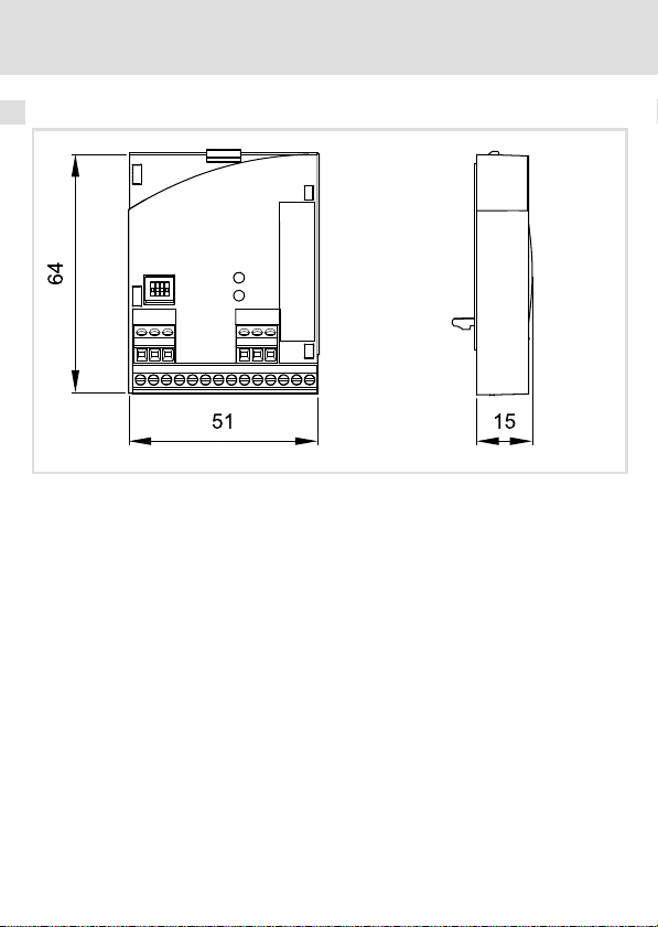
Abmessungen
alle Maße in mm
E82ZAFI004B
14
l
EDK82ZAFIC−001 DE/EN/FR 5.0
Page 15

Mechanische Installation 5
5 Mechanische Installation
Folgen Sie zur mechanischen Installation des Funktionsmoduls den Hinweisen in der Montageanleitung des Grundgerätes.
Die Montageanleitung des Grundgerätes ...
ƒ ist Teil des Lieferumfangs und liegt jedem Gerät bei.
ƒ gibt Hinweise, um Beschädigungen durch unsachgemäße Behandlung zu vermeiden.
ƒ beschreibt die einzuhaltende Reihenfolge der Installationsschritte.
EDK82ZAFIC−001 DE/EN/FR 5.0
l
15
Page 16

6 Elektrische Installation
EMV−gerechte Verdrahtung
6 Elektrische Installation
EMV−gerechte Verdrahtung
Für eine EMV−gerechte Verdrahtung beachten Sie folgende Punkte:
) Hinweis!
ƒ Steuer−/Datenleitungen getrennt von Motorleitungen verlegen.
ƒ Legen Sie die Schirme der Steuer−/Datenleitungen bei digitalen Signalen
beidseitig auf.
ƒ Zur Vermeidung von Potenzialdifferenzen zwischen den
Kommunikationsteilnehmern eine Ausgleichsleitung mit einem
Querschnitt von mindestens 16mm
ƒ Beachten Sie die weiteren Hinweise zur EMV−gerechten Verdrahtung in der
Dokumentation des Grundgerätes.
Vorgehensweise bei der Verdrahtung
1. Bustopologie einhalten, deshalb keine Stichleitungen verwenden.
2. Hinweise und Verdrahtungsvorschriften in den Unterlagen zum Steuerungssystem
beachten.
3. Nur Kabel verwenden, die den aufgeführten Spezifikationen entsprechen (^ 18).
4. Hinweise zur Spannungsversorgung des Funktionsmoduls beachten (^ 19).
2
einsetzen (Bezug:PE).
16
l
EDK82ZAFIC−001 DE/EN/FR 5.0
Page 17
Verdrahtung mit einem Leitrechner
1
Elektrische Installation
Verdrahtung mit einem Leitrechner
6
3
GG
+
E82ZAFICxxx
222
400 m
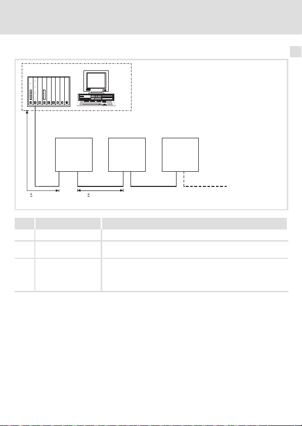
Nr. Element Beschreibung
1 Leitrechner z. B. PC oder SPS mit INTERBUS Master−Anschaltbaugruppe
2 Buskabel Verbindet die INTERBUS Master−Anschaltbaugruppe mit den Funkti-
3 INTERBUS−Slave Einsetzbares Grundgerät (^ 8) mit Funktionsmodul.
EDK82ZAFIC−001 DE/EN/FR 5.0
E82ZAFICxxx
400 m
onsmodulen.
l DIP−Schalter S1 einstellen ( ^ 29):
3
GG
+
– Einstellung für den letzten Busteilnehmer = OFF
– Einstellung für alle anderen Busteilnehmer = ON
E82ZAFICxxx
l
GG
3
+
E82ZAFI008
17
Page 18

6 Elektrische Installation
Verdrahtung mit einem Leitrechner
Spezifikation des Übertragungskabels
Allgemeine Eigenschaften
Kabeltyp Meterware,
Leiteranzahl 3 × 2, paarig verseilt, mit gemeinsamer Abschirmung
Leiterquerschnitt > 0.2 mm
DC−Leitungswiderstand
Impedanz (charakteristisch)
Kapazitätsbelag < 60 nF/km (f = 800 Hz)
(z. B. PHOENIX CONTACT: IBS RBC Meter−T, Best.−Nr.
28 06 28 6)
2
< 96 W/km
l 120 W ± 20 % (f = 64 kHz)
l 100 W ± 15 W (f > 1 MHz)
18
l
EDK82ZAFIC−001 DE/EN/FR 5.0
Page 19

Elektrische Installation
Spannungsversorgung
Spannungsversorgung
Interne DC−Spannungsversorgung
Die interne Spannung ...
ƒ dient der Versorgung der Reglersperre (CINH).
ƒ steht an Klemme X3.3/20 zur Verfügung.
Externe Spannungsversorgung
) Hinweis!
Verwenden Sie bei externer Spannungsversorgung und bei größeren
Entfernungen zwischen den Schaltschränken in jedem Schaltschrank immer
ein separates und nach EN 61800−5−1 sicher getrenntes Netzteil (SELV/PELV).
Die externe Spannungversorgung der Kommunikationsbaugruppe ist dann notwendig,
wenn beim Ausfall der Versorgung des Grundgerätes die Kommunikation über den Feldbus
bestehen bleiben soll.
) Hinweis!
Bei externer Spannungsversorgung des Funktionsmoduls wird der aktive
Busabschluss−Widerstand unabhängig vom Betrieb des Grundgerätes gespeist.
Das Bussystem bleibt dadurch auch dann weiter aktiv, wenn das Grundgerät
abgeschaltet wird oder ausfallen sollte.
6
EDK82ZAFIC−001 DE/EN/FR 5.0
l
19
Page 20
6 Elektrische Installation
Spannungsversorgung
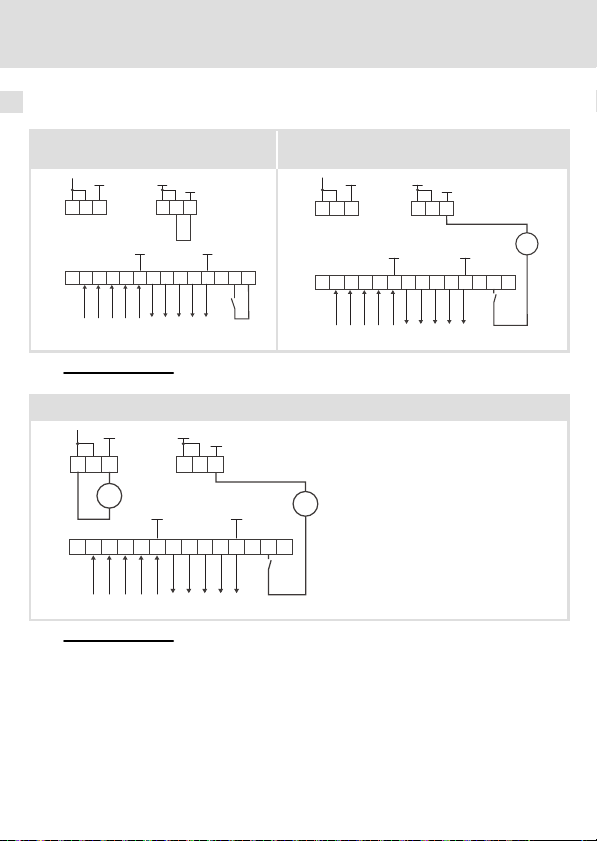
Versorgung der Reglersperre (CINH)
Versorgung über die interne
Spannungsquelle (X3.3/20)
GND1
5959
X3.1
ABCDE FGHJ K ++ 28 20
X3.3
7
GND1
GND2
39
77
X3.2
GND3 GND1
E82ZAFI001 E82ZAFI002
Für den Betrieb notwendige Mindestverdrahtung
Versorgung von Funktionsmodul und Reglersperre (CINH) über die externe Spannungsquelle
GND1
7
5959
X3.1
+
ABCDEFGHJK+ 28 20
X3.3
GND1
X3.2
_
+
GND3 GND1
GND2
39
77
Für den Betrieb notwendige Mindestverdrahtung
Versorgung über die externe Spannungsquelle
GND1
7
5959
X3.1
+20V
ABCDE FGHJ K ++ 28 20
X3.3
GND1
X3.2
GND3 GND1
_
+
+20V
GND2
39
77
+20V
E82ZAFI003
_
+
20
l
EDK82ZAFIC−001 DE/EN/FR 5.0
Page 21

Elektrische Installation
Belegung der Anschlussklemmen
Belegung der Anschlussklemmen
Klemme
X3.1/
59 Externe Spannungsversorgung des Funktionsmoduls
7 GND1 Bezugspotenzial für Klemme X3.3/20
Klemme
X3.2/
7 GND1 Bezugspotenzial für Klemme X3.3/20
39 GND2 Bezugspotenzial der Reglersperre (CINH) an Klemme X3.3/28
Klemme
X3.3/
A /DO1
B DO1
C /DI1
D DI1
E GND3 Bezugspotenzial für ankommende Datenleitung
F /DO2
G DO2
H /DI2
J DI2
K GND1 Bezugspotenzial für abgehende Datenleitung
+
28 CINH Reglersperre
20 DC−Spannungsquelle zur internen Versorgung der Reglersperre
Bezeichnung Funktion / Pegel
l U = 24 V DC (21.6 V − 0% ... 26.4 V + 0 %)
l Stromaufnahme an 24 V DC: I = 90 mA
Beim Durchschleifen der Versorgungsspannung zu anderen
Busteilnehmern über die Klemme 59 darf der fließende Strom max.
3 A betragen.
Bezeichnung Funktion / Pegel
Bezeichnung Funktion / Pegel
RS485 Datenleitung (ankommende)
RS485 Datenleitung (abgehende)
Zusätzlicher HF−Schirmabschluss
l Eingangswiderstand: 3.3 kW
l Start = HIGH (+12 ... +30 V DC)
l Stop = LOW (0 ... +3 V DC)
(CINH)
l +20 V DC (Bezug: GND1)
l I
= 10 mA
max
6
EDK82ZAFIC−001 DE/EN/FR 5.0
l
21
Page 22
6 Elektrische Installation
Leitungsquerschnitte und Schraubenanzugsmomente
Leitungsquerschnitte und Schraubenanzugsmomente
Bereich Werte
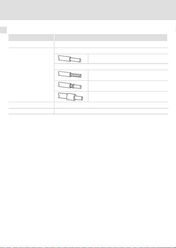
Elektrischer Anschluss Klemmenleiste mit Schraubanschluss
Anschlussmöglichkeiten
Anzugsmoment 0.22 ... 0.25 Nm (1.9 ... 2.2 lb−in)
Abisolierlänge 5 mm
starr:
flexibel:
2
1.5 mm
(AWG 16)
ohne Aderendhülse
2
(AWG 18)
1.0 mm
mit Aderendhülse, ohne Kunststoffhülse
2
(AWG 20)
0.5 mm
mit Aderendhülse, mit Kunststoffhülse
2
(AWG 20)
0.5 mm
22
l
EDK82ZAFIC−001 DE/EN/FR 5.0
Page 23

Inbetriebnahme
Vor dem ersten Einschalten
7 Inbetriebnahme
Vor dem ersten Einschalten
( Stop!
Bevor Sie das Grundgerät mit dem Funktionsmodul erstmalig einschalten,
überprüfen Sie ...
ƒ die gesamte Verdrahtung auf Vollständigkeit, Kurzschluss und Erdschluss.
ƒ die Einstellung des DIP−Schalters S1 (^ 29):
– Einstellung für den letzten Busteilnehmer = OFF
– Einstellung für alle anderen Busteilnehmer = ON
7
EDK82ZAFIC−001 DE/EN/FR 5.0
l
23
Page 24

7 Inbetriebnahme
Inbetriebnahmeschritte
Inbetriebnahmeschritte
) Hinweis!
Halten Sie unbedingt die Einstellreihenfolge ein.
Die schrittweise Inbetriebnahme des Funktionsmoduls mit der DRIVECOM−Gerätesteuerung ist nachfolgend beschrieben.
Schritt Vorgehensweise Ausführliche
1. Leitrechner (Master) für die Kommunikation mit dem Funktionsmo-
2. Grundgerät über Klemme 28 (CINH) sperren.
3. DIP−Schalter S1 einstellen:
4. Nutzdatenlänge festlegen über ...
5.
6.
7. Wird PCP−Kommunikation verwendet, PCP−Dienst "Initiate" durch-
dul konfigurieren.
l Klemme 28 auf LOW−Pegel legen.
l Das Grundgerät kann später über den Bus gesperrt und freigege-
ben werden.
l Einstellung für den letzten Busteilnehmer = OFF
l Einstellung für alle anderen Busteilnehmer = ON
l die DIP−Schalter S2 ... S4 oder
l Codestelle C1515
Netzspannung zuschalten und, wenn vorhanden, separate Spannungsversorgung des Funktionsmoduls zuschalten.
l Das Grundgerät ist nach ca. 1 Sekunde betriebsbereit.
l Die Reglersperre (CINH) ist aktiv.
Reaktion
l Die grüne LED "Verbindungsstatus zum Grundgerät" auf der
Frontseite des Funktionsmoduls leuchtet (nur sichtbar beim 8200
vector).
l Keypad: dc (falls aufgesteckt)
Sie können jetzt mit dem Grundgerät kommunizieren, d. h. alle Codestellen lesen und alle beschreibbaren Codestellen an Ihre Anwendung
anpassen.
Reaktion
Die gelbe LED auf dem Funktionsmodul blinkt, wenn der INTERBUS
aktiv ist.
führen.
l Jetzt können Sie mit den PCP−Diensten "Read" und "Write" auf
die Parameter des Grundgerätes zugreifen.
Information
^ 26
Dokumentation
des Grundgerätes
^ 29
^ 27
^ 30
^ 31
Dokumentation
des Grundgerätes
^ 31
Kommunikationshandbuch
INTERBUS
24
l
EDK82ZAFIC−001 DE/EN/FR 5.0
Page 25

Inbetriebnahme
Inbetriebnahmeschritte
7
VorgehensweiseSchritt
8. Funktionsmodul als Quelle für Steuerbefehle und Sollwerte wählen.
9.
10.
11. Prozess−Ausgangsdaten mit C1512 = 255 freigeben.
12. Grundgerät über Klemme 28 (CINH) freigeben.
13. Sollwert vorgeben.
14. In den Zustand EINSCHALTBEREIT wechseln:
15. Das Grundgerät ist im Zustand EINSCHALTBEREIT.
16. In den Zustand BETRIEB−FREIGEGEBEN wechseln.
17. Der Antrieb läuft jetzt an.
l C0005 = 200 einstellen.
– Eine Vorkonfiguration für den Betrieb mit dem Funktions-
modul wird durchgeführt.
– Steuerworte und Statusworte sind dabei bereits verknüpft.
Über C1511 die Prozess−Ausgangsdatenwörter (PAW) des Masters
den Prozess−Eingansdatenwörtern des Grundgerätes zuordnen.
Lenze−Einstellung:
PAW1: DRIVECOM−Steuerwort (DRIVECOM CTRL)
PAW2:
Sollwert1 (NSET1−N1)
PAW3: Sollwert2 (NSET1−N2)
PAW4:
Über C1510 die Prozess−Ausgangsdatenwörter des Grundgerätes den
Prozess−Eingansdatenwörtern (PEW) des Masters zuordnen.
Lenze−Einstellung:
Nur notwendig wenn C1511 verändert wurde.
l Klemme 28 auf HIGH−Pegel legen.
l Der Master sendet den Sollwert über das gewählte Prozess−Aus-
gangsdatenwort.
l Der Master sendet das DRIVECOM−Steuerwort:
0000 0000 0111 1110
l Der Master empfängt das DRIVECOM−Statuswort:
xxxx xxxx x01x 0001
l Der Master sendet das DRIVECOM−Steuerwort:
0000 0000 0111 1111
Zusatzsollwert (PCTRL1−NADD)
PEW1: DRIVECOM−Statuswort (DRIVECOM STAT)
Ausgangsfrequenz mit Schlupf (MCTRL1−NOUT+SLIP)
PEW2:
PEW3: Ausgangsfrequenz ohne Schlupf (MCTRL1−NOUT)
PEW4:
Motor−Scheinstrom (MCTRL1−IMOT)
(007E
(007F
hex
hex
).
).
bin
bin.
bin
Ausführliche
Information
Kommunikationshandbuch
INTERBUS
Kommunikationshandbuch
INTERBUS
Kommunikationshandbuch
INTERBUS
EDK82ZAFIC−001 DE/EN/FR 5.0
l
25
Page 26

7 Inbetriebnahme
Leitsystem (Master) konfigurieren
Leitsystem (Master) konfigurieren
Zur Kommunikation mit dem Funktionsmodul muss zunächst der Leitrechner (Master) konfiguriert werden.
Einstellungen am Master
Zur Projektierung des INTERBUS muss in der Projektierungssoftware des Masters die Gerätebeschreibungsdatei (EDS−Datei) der Kommunikationsbaugruppe eingelesen werden.
Die EDS−Datei können Sie im Download−Bereich unter http://www.Lenze.com herunterladen.
26
l
EDK82ZAFIC−001 DE/EN/FR 5.0
Page 27
Inbetriebnahme
Nutzdatenlänge festlegen
Nutzdatenlänge festlegen
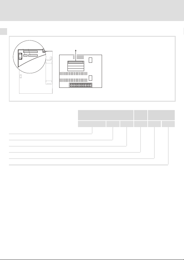
Die Anzahl der Prozessdaten−Wörter (PZD) und Parameterdaten−Wörter (PCP) können Sie
über die Codestelle C1515 oder die DIP−Schalter S2 ... S4 einstellen.
) Hinweis!
ƒ Summe aller Datenwörter (PZD + PCP): max. 4 Wörter
ƒ Schalten Sie die Spannungsversorgung des Funktionsmoduls und des
Antriebsreglers aus und anschließend wieder ein, um geänderte
Einstellungen zu aktivieren.
Einstellungen über DIP−Schalter S2 ... S4
7
ON
1ON234
ƒ Sobald einer der DIP−Schalter S2 ... S4 = OFF eingestellt ist, werden beim Einschalten
die Konfigurationen aus allen Schalterstellungen aktiv.
ƒ Bei ungültiger Schalterstellung wird die Lenze−Einstellung aktiv:
– DIP−Schalter S2 ... S4 = OFF (2 PZD−Wörter + 1 PCP−Wort)
ƒ Über Codestelle C1525 können Sie die aktuellen Stellungen der DIP−Schalter S2 ... S4
abfragen.
DIP−Schalter
S2 S3 S4
OFF OFF OFF 0 2 1 227
ON OFF OFF 1 3 1 227
OFF OFF ON 4 2 0 3
ON OFF ON 5 4 0 3
ON ON ON Codestelle C1515 aktiv.
EDK82ZAFIC−001 DE/EN/FR 5.0
Wertigkeit Anzahl Prozessdaten−
OFF
Wörter (PZD)
l
Anzahl Parameterdaten−Wörter (PCP)
E82ZAFI009
ID−Code
27
Page 28

7 Inbetriebnahme
Nutzdatenlänge festlegen
Einstellungen über Codestelle
ƒ DIP−Schalter S2 ... S4 = ON
ƒ Die Anzahl der Datenwörter (PZD + PCP) über C1515 einstellen.
Code
C1515
Subcode Lenze Werte Zugriff Datentyp
− 0
Werte Beschreibung
0, 1, 4, 5 Die Konfiguration aus den DIP−Schalterstellungen wird entsprechend
11 ... 14
21 ... 23
Name
Prozess−/Parameterdaten−Spezifikation
0, 1, 4, 5
11 ... 14
21 ... 23
der eingegebenen Wertigkeit übernommen.
l kein PCP
l 11 (1 Wort PZD) ... 14 (4 Wörter PZD)
l 1 Wort PCP
l 21 (1 Wort PZD) ... 23 (3 Wörter PZD)
0x5A14 (23060)
rw FIX32
Index
28
l
EDK82ZAFIC−001 DE/EN/FR 5.0
Page 29

Einstellung für letzten Busteilnehmer
DIP−Schalter 1
Einstellung für letzten Busteilnehmer
Inbetriebnahme
ON
7
1ON234
OFF
) Hinweis!
ƒ Nur beim physikalisch letzten Busteilnehmer muss der DIP−Schalter 1
auf OFF eingestellt sein.
ƒ Lenze−Einstellung: alle Schalter OFF
Stellung Hinweise
OFF Grundgerät mit Funktionsmodul ist letzter Bus−Teilnehmer
ON Grundgerät mit Funktionsmodul ist nicht letzter Bus−Teilnehmer.
E82ZAFI009
EDK82ZAFIC−001 DE/EN/FR 5.0
l
29
Page 30

7 Inbetriebnahme
Netzspannung zuschalten
Netzspannung zuschalten
) Hinweis!
Wenn Sie die externe Spannungsversorgung des Funktionsmoduls benutzen,
schalten Sie diese ebenfalls ein.
ƒ Nach dem Einschalten der Versorgungsspannung ist das Grundgerät nach ca. 1 s
betriebsbereit.
ƒ Die Reglersperre ist aktiv.
ƒ Die grüne LED auf der Frontseite des Funktionsmoduls leuchtet.
Schutz vor unkontrolliertem Wiederanlauf
) Hinweis!
Aufbau der Kommunikation
Zum Aufbau der Kommunikation ist es beim extern versorgten
Funktionsmodul erforderlich, auch das Grundgerät anfangs einzuschalten.
ƒ Die weitere Kommunikation des extern versorgten Moduls bleibt
anschließend unabhängig vom Einschaltzustand des Grundgerätes.
Schutz vor unkontrolliertem Wiederanlauf
Nach einer Störung (z. B. kurzzeitiger Netzausfall) ist der Wiederanlauf eines
Antriebs in manchen Fällen unerwünscht oder sogar unzulässig.
In C0142 lässt sich das Wiederanlaufverhalten des Antriebsreglers einstellen:
ƒ C0142 = 0 (Lenze−Einstellung)
– Der Antriebsregler bleibt gesperrt (auch wenn die Störung nicht mehr
aktiv ist).
– Der Antrieb läuft kontrolliert an durch explizite Reglerfreigabe:
LOW−HIGH−Flanke an Klemme 28 (CINH)
ƒ C0142 = 1
– Ein unkontrollierter Anlauf des Antriebs ist möglich.
30
l
EDK82ZAFIC−001 DE/EN/FR 5.0
Page 31

8 Diagnose
LED−Statusanzeigen
LED
Pos. Farbe Zustand
A gelb
B grün
aus Keine Kommunikation mit dem INTERBUS−Master vorhanden.
blinkt Die Kommunikation über das Funktionsmodul zum INTERBUS−
an Interner Fehler des Funktionsmoduls
aus
blinkt Das Funktionsmodul ist mit Spannung versorgt, hat aber keine
an Das Funktionsmodul ist mit Spannung versorgt und hat eine Ver-
Diagnose
LED−Statusanzeigen
E82ZAFIxxx
Beschreibung
Master ist aufgebaut.
l Das Funktionsmodul wird nicht mit Spannung versorgt.
l Das Grundgerät und/oder die externe Spannungsversorgung
ist ausgeschaltet.
Verbindung zum Grundgerät.
Ursachen:
l Das Grundgerät ist abgeschaltet.
l Das Grundgerät ist in der Initialisierungsphase.
l Das Grundgerät ist nicht vorhanden.
bindung zum Grundgerät.
8
EDK82ZAFIC−001 DE/EN/FR 5.0
l
31
Page 32

Legend for fold−out page
Pos. Description Detailed
A LED (yellow): Status of the INTERBUS communication
B LED (green): Connection status to the controller
C
DIP switch S1
l Setting for the last node = OFF
l Setting for all other nodes = ON
DIP switches S2 ... S4
l Configuration of
– the process data words (PCD)
– the parameter data words (PCP)
D Plug connector X3.1
E Plug connector X3.2
F Plug connector X3.3
G Nameplate ^ 38
0Fig. 0Tab. 0
– the ID codes
l Connection for external voltage supply of the function module
l Reference terminal GND1, e.g. for external voltage supply of the function
module
l Reference terminal GND2, e.g. for external supply of the controller inhibit
(CINH)
l Connection for
– INTERBUS
– controller inhibit (CINH)
– internal supply of the controller inhibit (CINH)
information
^ 59
^ 57
^ 41
32
l
EDK82ZAFIC−001 DE/EN/FR 5.0
Page 33

Contents i
1 About this documentation 34. . . . . . . . . . . . . . . . . . . . . . . . . . . . . . . . . . . . . . . . . . . .
2 Safety instructions 35. . . . . . . . . . . . . . . . . . . . . . . . . . . . . . . . . . . . . . . . . . . . . . . . . . .
3 Product description 36. . . . . . . . . . . . . . . . . . . . . . . . . . . . . . . . . . . . . . . . . . . . . . . . . .
Function 36. . . . . . . . . . . . . . . . . . . . . . . . . . . . . . . . . . . . . . . . . . . . . . . . . . . . . . . . . . .
Application as directed 36. . . . . . . . . . . . . . . . . . . . . . . . . . . . . . . . . . . . . . . . . . . . . .
Scope of supply 37. . . . . . . . . . . . . . . . . . . . . . . . . . . . . . . . . . . . . . . . . . . . . . . . . . . . . .
Identification 38. . . . . . . . . . . . . . . . . . . . . . . . . . . . . . . . . . . . . . . . . . . . . . . . . . . . . . .
4 Technical data 39. . . . . . . . . . . . . . . . . . . . . . . . . . . . . . . . . . . . . . . . . . . . . . . . . . . . . . .
General data 39. . . . . . . . . . . . . . . . . . . . . . . . . . . . . . . . . . . . . . . . . . . . . . . . . . . . . . .
Operating conditions 40. . . . . . . . . . . . . . . . . . . . . . . . . . . . . . . . . . . . . . . . . . . . . . . . .
Protective insulation 40. . . . . . . . . . . . . . . . . . . . . . . . . . . . . . . . . . . . . . . . . . . . . . . . .
Connection terminals 41. . . . . . . . . . . . . . . . . . . . . . . . . . . . . . . . . . . . . . . . . . . . . . . .
Dimensions 42. . . . . . . . . . . . . . . . . . . . . . . . . . . . . . . . . . . . . . . . . . . . . . . . . . . . . . . . .
5 Mechanical installation 43. . . . . . . . . . . . . . . . . . . . . . . . . . . . . . . . . . . . . . . . . . . . . . .
6 Electrical installation 44. . . . . . . . . . . . . . . . . . . . . . . . . . . . . . . . . . . . . . . . . . . . . . . . .
Wiring according to EMC 44. . . . . . . . . . . . . . . . . . . . . . . . . . . . . . . . . . . . . . . . . . . . . .
Wiring to a host 45. . . . . . . . . . . . . . . . . . . . . . . . . . . . . . . . . . . . . . . . . . . . . . . . . . . . .
Voltage supply 47. . . . . . . . . . . . . . . . . . . . . . . . . . . . . . . . . . . . . . . . . . . . . . . . . . . . .
Assignment of the terminals 49. . . . . . . . . . . . . . . . . . . . . . . . . . . . . . . . . . . . . . . . . .
Cable cross−sections and screw−tightening torques 50. . . . . . . . . . . . . . . . . . . . . . . .
7 Commissioning 51. . . . . . . . . . . . . . . . . . . . . . . . . . . . . . . . . . . . . . . . . . . . . . . . . . . . .
Before switching on 51. . . . . . . . . . . . . . . . . . . . . . . . . . . . . . . . . . . . . . . . . . . . . . . . .
Commissioning steps 52. . . . . . . . . . . . . . . . . . . . . . . . . . . . . . . . . . . . . . . . . . . . . . . . .
Configuring the host system (master) 54. . . . . . . . . . . . . . . . . . . . . . . . . . . . . . . . . .
Defining the user data length 55. . . . . . . . . . . . . . . . . . . . . . . . . . . . . . . . . . . . . . . . . .
Setting for last bus node 57. . . . . . . . . . . . . . . . . . . . . . . . . . . . . . . . . . . . . . . . . . . . . .
Connecting the mains voltage 58. . . . . . . . . . . . . . . . . . . . . . . . . . . . . . . . . . . . . . . . .
8 Diagnostics 59. . . . . . . . . . . . . . . . . . . . . . . . . . . . . . . . . . . . . . . . . . . . . . . . . . . . . . . . .
LED status displays 59. . . . . . . . . . . . . . . . . . . . . . . . . . . . . . . . . . . . . . . . . . . . . . . . . . .
EDK82ZAFIC−001 DE/EN/FR 5.0
l
33
Page 34

1 About this documentation
1 About this documentation
Contents
This documentation includes ...
ƒ Safety instructions which you must observe in any case;
ƒ Data about the versions of Lenze standard devices to be used;
ƒ Information about the mechanical and electrical installation of the function module;
ƒ Information about the commissioning of the function module;
ƒ Technical data.
Validity information
The information given in this documentation is valid for the following devices:
Function module Type designation From hardware version From software version
INTERBUS E82ZAFIC001 4A 20
Target group
This documentation is intended for persons who install and commission the described
product according to the project requirements.
I Tip!
Information and auxiliary devices related to the Lenze products can be found
in the download area at
http://www.Lenze.com
34
l
EDK82ZAFIC−001 DE/EN/FR 5.0
Page 35

Safety instructions 2
2 Safety instructions
} Danger!
Inappropriate handling of the function module and the standard device can
cause serious injuries to persons and damage to material assets.
Observe the safety instructions and residual hazards included in the
documentation of the standard device.
( Stop!
Electrostatic discharge
Electronic components within the function module can be damaged or
destroyed by electrostatic discharge.
Possible consequences:
ƒ The function module is defective.
ƒ Fieldbus communication is not possible or faulty.
Protective measures
ƒ Free yourself from any electrostatic charge before you touch the module.
EDK82ZAFIC−001 DE/EN/FR 5.0
l
35
Page 36

3 Product description
Function
3 Product description
Function
The function module connects the standard device to the INTERBUS communication
system.
Application as directed
The function module ...
ƒ is an accessory module for use in conjunction with the following Lenze standard
devices:
Product series Device name From hardware version
Frequency inverter
ƒ connects Lenze standard devices to the serial INTERBUS communication system.
ƒ is a device intended for use in industrial power systems.
Any other use shall be deemed inappropriate!
8200 vector Vx14
8200 motec Vx14
I Tip!
For more information about the function module, please see the
corresponding communication manual.
The PDF file is available in the download area at:
http://www.Lenze.com
36
l
EDK82ZAFIC−001 DE/EN/FR 5.0
Page 37

Scope of supply
Product description
Scope of supply
7
8
3
Pos. Scope of supply
E82ZAFIC001function module
Mounting Instructions
Screwdriver
7
Adhesive tape
8
EDK82ZAFIC−001 DE/EN/FR 5.0
l
E82ZAFI007/E82ZAFI004B
37
Page 38

3 Product description
APPLICATION
010 / 3A22
Identification
Identification
APPLICATION
010/ 3A22
Product series
INTERBUS
Version
Variant 001: coated version
Hardware version
Software version
L
Type
Id.-No.
Prod.-No.
Ser.-No.
E82AF000P0B201XX
E82ZAFX005
E82ZAF I C 001 4A 20
38
l
EDK82ZAFIC−001 DE/EN/FR 5.0
Page 39

Technical data
General data
4 Technical data
General data
Field Values
Order designation E82ZAFIC001
Communication medium RS485
Network topology Ring (go and return line in the same cable)
Number of bus nodes Dependent on INTERBUS master (e.g. Phoenix Contact G4 master).
Distance between two bus
nodes
INTERBUS identification
(ID code)
Drive profile DRIVECOM profile "Drive technology 20"
INTERBUS node Slave
Baud rate 500 kbps
Process data words (PCD),
16 bits
Parameter data words (PCP),
16 bits
PDU length Max. 64 bytes
Supported PCP services
Communication time
For the following data, which depend on whether PCP
communication is used or not, always the smaller value applies:
l with PCP communication: max. 62 or
l without PCP communication: max. 256/number of PCDs
Max. 400 m
l With 1 word PCP: 227 (0xE3)
l Without PCP: 3 (0x03)
1 ... 4 words
0 or 1 word
l Initiate
l Abort
l Status
l Identify
l Get−0V−long
l Read
l Write
l Sum of the cycle time and the processing time in the bus nodes.
The times are independent of each other.
l Processing time in the standard device
– Parameter data (PCP): approx. 30 ms + 20 ms tolerance
– Process data (PCD): approx. 3 ms + 2 ms tolerance
4
EDK82ZAFIC−001 DE/EN/FR 5.0
l
39
Page 40

4 Technical data
Operating conditions
Operating conditions
Ambient conditions
Climate
Storage
Transport IEC/EN 60721−3−2 2K3 (−25 to +70 °C)
Operation Corresponding to the data of the Lenze standard device used (see
Pollution EN 61800−5−1 Degree of pollution 2
Degree of protection IP20 (protection against accidental contact according to NEMA 250 type 1)
Protective insulation
Insulation between incoming bus and ... Type of insulation (acc. to EN 61800−5−1)
l 8200 vector/motec power section
l Reference earth / PE
l Terminal X3.1/59
l Terminal X3.3/20
l Terminal X3.3/28
Insulation between incoming bus and ... Type of insulation (acc. to EN 61800−5−1)
Outgoing bus Functional insulation
Insulation between outgoing bus and ... Type of insulation (acc. to EN 61800−5−1)
l 8200 vector/motec power section
l Reference earth / PE
l Terminal X3.1/59
l Terminal X3.3/20
l Terminal X3.3/28
IEC/EN 60721−3−1 1K3 (−25 to +60 °C)
documentation of the standard device).
Reinforced insulation
Functional insulation
Functional insulation
Functional insulation
Functional insulation
Reinforced insulation
Functional insulation
No electrical isolation
No electrical isolation
Functional insulation
40
l
EDK82ZAFIC−001 DE/EN/FR 5.0
Page 41

Technical data
Connection terminals
Connection terminals
Terminal
X3.1/
59 External voltage supply of the function module
7 GND1 Reference potential for terminal X3.3/20
Terminal
X3.2/
7 GND1 Reference potential for terminal X3.3/20
39 GND2 Reference potential for controller inhibit (CINH) on terminal X3.3/28
Terminal
X3.3/
A /DO1
B DO1
C /DI1
D DI1
E GND3 Reference potential for incoming data line
F /DO2
G DO2
H /DI2
J DI2
K GND1 Reference potential for outgoing data line
+
28 CINH Controller inhibit
20 DC voltage source for internal supply of controller inhibit (CINH)
Designation Function / level
l U = 24 V DC (21.6 V − 0% ... 26.4 V + 0 %)
l Current consumption for 24 V DC: I = 90 mA
If the supply voltage is looped through to other bus nodes via
terminal 59, the current flowing must not exceed 3 A.
Designation Function / level
Designation Function / level
RS485 data line (incoming)
RS485 data line (outgoing)
Additional HF shield termination
l Input resistance: 3.3 kW
l Start = HIGH (+12 ... +30 V DC)
l Stop = LOW (0 ... +3 V DC)
l +20 V DC (reference: GND1)
l I
= 10 mA
max
4
EDK82ZAFIC−001 DE/EN/FR 5.0
l
41
Page 42

4 Technical data
Dimensions
Dimensions
All dimensions in mm
E82ZAFI004B
42
l
EDK82ZAFIC−001 DE/EN/FR 5.0
Page 43

Mechanical installation 5
5 Mechanical installation
Follow the notes given in the Mounting Instructions for the standard device for the
mechanical installation of the function module.
The Mounting Instructions for the standard device ...
ƒ are part of the scope of supply and are enclosed with each device.
ƒ provide tips to avoid damage provide tips to avoid damage through improper
handling.
ƒ describe the obligatory order of installation steps.
EDK82ZAFIC−001 DE/EN/FR 5.0
l
43
Page 44

6 Electrical installation
Wiring according to EMC
6 Electrical installation
Wiring according to EMC
For wiring according to EMC requirements observe the following points:
) Note!
ƒ Separate control cables/data lines from motor cables.
ƒ Connect the shields of control cables/data lines at both ends in the case of
digital signals.
ƒ Use an equalizing conductor with a cross−section of at least 16mm
(reference:PE) to avoid potential differences between the bus nodes.
ƒ Observe the other notes concerning EMC−compliant wiring given in the
documentation for the standard device.
Wiring procedure
1. Observe the bus topology, do not use any stubs.
2. Follow the wiring notes given in the documentation for the control system.
3. Only use cables which comply with the specifications listed (^ 46).
4. Observe the notes concerning the voltage supply of the function module (^ 47).
2
44
l
EDK82ZAFIC−001 DE/EN/FR 5.0
Page 45

Wiring to a host
Electrical installation
6
Wiring to a host
1
3
GG
+
E82ZAFICxxx
222
400 m
No. Element Description
1 Host E.g. PC or PLC with INTERBUS master interface module
2 Bus cable Connects the INTERBUS master interface module to the function
3 INTERBUS slave Applicable standard device (^ 36) with function module.
EDK82ZAFIC−001 DE/EN/FR 5.0
E82ZAFICxxx
400 m
modules.
l Set DIP switch S1 ( ^ 57):
3
GG
+
– Setting for the last node = OFF
– Setting for all other nodes = ON
E82ZAFICxxx
l
GG
3
+
E82ZAFI008
45
Page 46

6 Electrical installation
Wiring to a host
Specification of the transmission cable
General characteristics
Cable type Sold by the meter,
Number of conductors 3 × 2, twisted pairs, with shared shield
Conductor cross−section > 0.2 mm
DC cable resistance
Impedance (characteristic)
Capacitance per unit length < 60 nF/km (f = 800 Hz)
(e.g. PHOENIX CONTACT: IBS RBC Meter−T, Order No.
28 06 28 6)
2
< 96 W/km
l 120 W ± 20 % (f = 64 kHz)
l 100 W ±15 W (f > 1 MHz)
46
l
EDK82ZAFIC−001 DE/EN/FR 5.0
Page 47

Electrical installation
Voltage supply
Voltage supply
Internal DC voltage supply
The internal voltage ...
ƒ supplies the controller inhibit (CINH).
ƒ is available at terminal X3.3/20.
External voltage supply
) Note!
In the case of an external voltage supply and for greater distances between the
control cabinets, always use a separate power supply unit (SELV/PELV) that is
safely separated in accordance with EN 61800−5−1 in each control cabinet.
External voltage supply of the communication module is required if communication via the
fieldbus is to be maintained even when the power supply of the standard device fails.
) Note!
With external voltage supply of the function module, the active bus
terminating resistor is fed independently of the operation of the standard
device. In this way, the bus system remains active even when the standard
device is switched off or fails.
6
EDK82ZAFIC−001 DE/EN/FR 5.0
l
47
Page 48

6 Electrical installation
Voltage supply
Supply of controller inhibit (CINH)
Supply via the internal voltage source
(X3.3/20)
GND1
5959
X3.1
ABCDE FGHJ K ++ 28 20
X3.3
7
GND1
GND2
39
77
X3.2
GND3 GND1
E82ZAFI001 E82ZAFI002
Minimum wiring required for operation
Supply of function module and controller inhibit (CINH) via external voltage source
GND1
7
5959
X3.1
+
ABCDEFGHJK+ 28 20
X3.3
GND1
X3.2
_
+
GND3 GND1
GND2
39
77
Minimum wiring required for operation
Supply via the external voltage source
GND1
7
5959
X3.1
+20V
ABCDE FGHJ K ++ 28 20
X3.3
_
+
+20V
GND1
X3.2
GND3 GND1
GND2
39
77
_
+
+20V
E82ZAFI003
48
l
EDK82ZAFIC−001 DE/EN/FR 5.0
Page 49

Electrical installation
Assignment of the terminals
Assignment of the terminals
Terminal
X3.1/
59 External voltage supply of the function module
7 GND1 Reference potential for terminal X3.3/20
Terminal
X3.2/
7 GND1 Reference potential for terminal X3.3/20
39 GND2 Reference potential for controller inhibit (CINH) on terminal X3.3/28
Terminal
X3.3/
A /DO1
B DO1
C /DI1
D DI1
E GND3 Reference potential for incoming data line
F /DO2
G DO2
H /DI2
J DI2
K GND1 Reference potential for outgoing data line
+
28 CINH Controller inhibit
20 DC voltage source for internal supply of controller inhibit (CINH)
Designation Function / level
l U = 24 V DC (21.6 V − 0% ... 26.4 V + 0 %)
l Current consumption for 24 V DC: I = 90 mA
If the supply voltage is looped through to other bus nodes via
terminal 59, the current flowing must not exceed 3 A.
Designation Function / level
Designation Function / level
RS485 data line (incoming)
RS485 data line (outgoing)
Additional HF shield termination
l Input resistance: 3.3 kW
l Start = HIGH (+12 ... +30 V DC)
l Stop = LOW (0 ... +3 V DC)
l +20 V DC (reference: GND1)
l I
= 10 mA
max
6
EDK82ZAFIC−001 DE/EN/FR 5.0
l
49
Page 50

6 Electrical installation
Cable cross−sections and screw−tightening torques
Cable cross−sections and screw−tightening torques
Range Values
Electrical connection Terminal strip with screw connection
Possible connections
Tightening torque 0.22 ... 0.25 Nm (1.9 ... 2.2 lb−in)
Bare end 5 mm
rigid:
flexible:
2
1.5 mm
(AWG 16)
without wire end ferrule
2
(AWG 18)
1.0 mm
with wire end ferrule, without plastic sleeve
2
(AWG 20)
0.5 mm
with wire end ferrule, with plastic sleeve
2
(AWG 20)
0.5 mm
50
l
EDK82ZAFIC−001 DE/EN/FR 5.0
Page 51

Commissioning
Before switching on
7 Commissioning
Before switching on
( Stop!
Before you switch on the standard device and the plugged−in function module
for the first time, check ...
ƒ the entire wiring for completeness, short circuit and earth fault.
ƒ the setting of the DIP switch S1 (^ 57):
– Setting for the last node = OFF
– Setting for all other nodes = ON
7
EDK82ZAFIC−001 DE/EN/FR 5.0
l
51
Page 52

7 Commissioning
Commissioning steps
Commissioning steps
) Note!
Do not change the setting sequence.
Step−by−step commissioning of the function module with the DRIVECOM device control is
described below.
Step Procedure Detailed
1. Configure the host (master) for communication via the function
2. Inhibit the standard device via terminal 28 (CINH).
3. Set DIP switch S1:
4. Define user data length via ...
5.
6.
7. If PCP communication is used, carry out the PCP service "initiate".
module.
l Set terminal 28 to LOW level.
l Later on the standard device can be inhibited and enabled via the
bus system.
l Setting for the last node = OFF
l Setting for all other nodes = ON
l DIP switches S2 ... S4 or
l code C1515
Connect the mains voltage and, if available, the separate voltage
supply for the function module.
l The standard device is ready for operation after approx. 1 second.
l Controller inhibit (CINH) is active.
Response
l The green LED "Connection status to standard device" at the front
of the function module is lit (only visible in the case of the 8200
vector).
l Keypad: dc(if attached)
It is now possible to communicate with the standard device, i.e. all
codes can be read and all writable codes can be adapted to the
application.
Response
The yellow LED on the function module is blinking when the
INTERBUS is active.
l It is now possible to access the parameters of the standard device
with the PCP services "read" and "write".
information
^ 54
Documentation
for the standard
device
^ 57
^ 55
^ 58
^ 59
Documentation
for the standard
device
^ 59
INTERBUS
communication
manual
52
l
EDK82ZAFIC−001 DE/EN/FR 5.0
Page 53

Commissioning
Commissioning steps
7
ProcedureStep
8. Select the function module as the source for control commands and
9.
10.
11. Enable process output data with C1512 = 255.
12. Enable the standard device via terminal 28 (CINH).
13. Select setpoint.
14. Change to the READY TO START state:
15. The standard device is in the READY TO START state.
16. Change to the OPERATION ENABLED state.
17. The drive starts up.
setpoints.
l Set C0005 = 200.
– A preconfiguration for operation with the function module is
carried out.
– This preconfiguration already links the control words and
status words.
Use C1511 to assign the process output data words (POW) of the
master to the process input data words of the standard device.
Lenze setting:
POW1: DRIVECOM control word (DRIVECOM CTRL)
Setpoint1 (NSET1−N1)
POW2:
POW3: Setpoint2 (NSET1−N2)
Additional setpoint (PCTRL1−NADD)
POW4:
Use C1510 to assign the process output data words of the standard
device to the process input data words (PIW) of the master.
Lenze setting:
PIW1: DRIVECOM status word (DRIVECOM STAT)
PIW2: Output frequency with slip (MCTRL1−NOUT+SLIP)
Output frequency without slip (MCTRL1−NOUT)
PIW3:
PIW4:
Apparent motor current (MCTRL1−IMOT)
Only required when C1511 has been changed.
l Set terminal 28 to HIGH level.
l The master transmits the setpoint via the selected process output
data word.
l The master transmits the DRIVECOM control word:
0000 0000 0111 1110
l The master receives the DRIVECOM status word:
xxxx xxxx x01x 0001
l The master transmits the DRIVECOM control word:
0000 0000 0111 1111
bin.
bin
bin
(007E
(007F
hex
hex
).
).
Detailed
information
INTERBUS
communication
manual
INTERBUS
communication
manual
INTERBUS
communication
manual
EDK82ZAFIC−001 DE/EN/FR 5.0
l
53
Page 54

7 Commissioning
Configuring the host system (master)
Configuring the host system (master)
For communication via the function module, first the host (master) must be configured.
Master settings
The configuration of the INTERBUS requires the device description file (EDS file) for the
communication module to be imported to the master configuration software.
The EDS file can be downloaded in the download area on http://www.Lenze.com.
54
l
EDK82ZAFIC−001 DE/EN/FR 5.0
Page 55

Defining the user data length
Defining the user data length
The number of process data words (PCD) and parameter data words (PCP) can be set via
code C1515 or via the DIP switches S2 ... S4.
) Note!
ƒ Sum of all data words (PZD + PCP): max. 4 words
ƒ Switch off the voltage supply of the function module and the controller
and then on again to activate the changed settings.
Settings via DIP switches S2 ... S4
ON
Commissioning
1ON234
ƒ If one of the DIP switches S2 ... S4 is set to OFF, the configurations resulting from all
switch positions are active at switch−on.
ƒ If the switch positions are invalid, the Lenze setting is activated:
– DIP switches S2 ... S4 = OFF (2 PCD words + 1 PCP word)
ƒ Code C1525 displays the current settings of the DIP switches S2 ... S4.
DIP switch
S2 S3 S4
OFF OFF OFF 0 2 1 227
ON OFF OFF 1 3 1 227
OFF OFF ON 4 2 0 3
ON OFF ON 5 4 0 3
ON ON ON Code C1515 active.
Value Number of process
OFF
data words (PCD)
Number of parameter
data words (PCP)
E82ZAFI009
ID code
7
EDK82ZAFIC−001 DE/EN/FR 5.0
l
55
Page 56

7 Commissioning
Defining the user data length
Settings via code
ƒ DIP switches S2 ... S4 = ON
ƒ Set the number of data words (PCD + PCP) via C1515.
Code
C1515
Subcode Lenze Values Access Data type
− 0
Values Description
0, 1, 4, 5 The configuration resulting from the values corresponding to the set
11 ... 14
21 ... 23
Name
Process/parameter data specification
0, 1, 4, 5
11 ... 14
21 ... 23
DIP switch positions becomes active.
l No PCP
l 11 (1 word PCD) ... 14 (4 words PCD)
l 1 word PCP
l 21 (1 word PCD) ... 23 (3 words PCD)
0x5A14 (23060)
rw FIX32
Index
56
l
EDK82ZAFIC−001 DE/EN/FR 5.0
Page 57

Setting for last bus node
DIP switch 1
ON
Commissioning
Setting for last bus node
7
1ON234
OFF
) Note!
ƒ DIP switch 1 must only be set to OFF for the last physical node.
ƒ Lenze setting: all switches OFF
Position Notes
OFF Standard device with function module is the last bus node
ON Standard device with function module is not the last bus node.
E82ZAFI009
EDK82ZAFIC−001 DE/EN/FR 5.0
l
57
Page 58

7 Commissioning
Connecting the mains voltage
Connecting the mains voltage
) Note!
If the external voltage supply of the function module is used, switch it on as
well.
ƒ The standard device is ready for operation approx. 1 s after switching on the supply
voltage.
ƒ The controller inhibit is active.
ƒ The green LED at the front of the function module is lit.
Protection against uncontrolled start−up
) Note!
Establishing communication
For establishing communication via an externally supplied function module,
the standard device must be switched on as well.
ƒ After communication has been established, the externally supplied module
is independent of the power on/off state of the standard device.
Protection against uncontrolled start−up
After a fault (e.g. short−term mains failure), a restart of the drive is not always
wanted and − in some cases − even not allowed.
The restart behaviour of the controller can be set in C0142:
ƒ C0142 = 0 (Lenze setting)
– The controller remains inhibited (even if the fault is no longer active).
– The drive starts in a controlled mode by explicitly enabling the
controller: LOW−HIGH edge at terminal 28 (CINH)
ƒ C0142 = 1
– An uncontrolled restart of the drive is possible.
58
l
EDK82ZAFIC−001 DE/EN/FR 5.0
Page 59

8 Diagnostics
LED status displays
LED
Pos. Colour Condition
A Yellow
B Green
Off No communication with the INTERBUS master.
Blinking Communication to the INTERBUS master via the function module
On Internal error in the function module
Off
Blinking The function module is supplied with voltage but not connected
On The function module is supplied with voltage and is connected to
Diagnostics
LED status displays
E82ZAFIxxx
Description
is established.
l The function module is not supplied with voltage.
l The standard device and/or the external voltage supply is/are
switched off.
to the standard device.
Causes:
l The standard device is switched off.
l The standard device is in the initialisation phase.
l The standard device is not available.
the standard device.
8
EDK82ZAFIC−001 DE/EN/FR 5.0
l
59
Page 60

Légende de l’illustration de la page dépliante
Pos. Description Informations
A LED (jaune) : état de la communication INTERBUS
B LED (verte) : état de la liaison avec le variateur
C
Interrupteur DIP S1
l Réglage du dernier participant au bus = OFF
l Réglage de tous les autres participants au bus = ON
Interrupteurs DIP S2 ... S4
l Configuration
– des mots de données process (PZD)
– des mots de données paramètres (PCP)
D Bornier X3.1
E Bornier X3.2
F Bornier X3.3
G Plaque signalétique ^ 66
0Fig. 0Tab. 0
– des codes ID
l Raccordement de l’alimentation externe du module de fonction
l Borne de référence GND1, par exemple pour l’alimentation externe du
module de fonction
l Borne de référence GND2, par exemple pour l’alimentation externe du
blocage variateur (CINH)
l Raccordements :
– INTERBUS
– blocage variateur (CINH)
– alimentation interne du blocage variateur (CINH)
détaillées
^ 88
^ 86
^ 69
60
l
EDK82ZAFIC−001 DE/EN/FR 5.0
Page 61

Sommaire i
1 Présentation du document 62. . . . . . . . . . . . . . . . . . . . . . . . . . . . . . . . . . . . . . . . . . . .
2 Consignes de sécurité 63. . . . . . . . . . . . . . . . . . . . . . . . . . . . . . . . . . . . . . . . . . . . . . . .
3 Description du produit 64. . . . . . . . . . . . . . . . . . . . . . . . . . . . . . . . . . . . . . . . . . . . . . . .
Fonction 64. . . . . . . . . . . . . . . . . . . . . . . . . . . . . . . . . . . . . . . . . . . . . . . . . . . . . . . . . . .
Utilisation conforme à la fonction 64. . . . . . . . . . . . . . . . . . . . . . . . . . . . . . . . . . . . .
Equipement livré 65. . . . . . . . . . . . . . . . . . . . . . . . . . . . . . . . . . . . . . . . . . . . . . . . . . . .
Identification 66. . . . . . . . . . . . . . . . . . . . . . . . . . . . . . . . . . . . . . . . . . . . . . . . . . . . . . .
4 Spécifications techniques 67. . . . . . . . . . . . . . . . . . . . . . . . . . . . . . . . . . . . . . . . . . . . .
Caractéristiques générales 67. . . . . . . . . . . . . . . . . . . . . . . . . . . . . . . . . . . . . . . . . . . .
Conditions d’utilisation 68. . . . . . . . . . . . . . . . . . . . . . . . . . . . . . . . . . . . . . . . . . . . . . .
Isolement de protection 68. . . . . . . . . . . . . . . . . . . . . . . . . . . . . . . . . . . . . . . . . . . . . .
Spécifications des bornes de raccordement 69. . . . . . . . . . . . . . . . . . . . . . . . . . . . . .
Encombrements 70. . . . . . . . . . . . . . . . . . . . . . . . . . . . . . . . . . . . . . . . . . . . . . . . . . . . .
5 Installation mécanique 71. . . . . . . . . . . . . . . . . . . . . . . . . . . . . . . . . . . . . . . . . . . . . . .
6 Installation électrique 72. . . . . . . . . . . . . . . . . . . . . . . . . . . . . . . . . . . . . . . . . . . . . . . .
Câblage conforme CEM 72. . . . . . . . . . . . . . . . . . . . . . . . . . . . . . . . . . . . . . . . . . . . . . .
Raccordement à un maître 73. . . . . . . . . . . . . . . . . . . . . . . . . . . . . . . . . . . . . . . . . . . .
Alimentation 75. . . . . . . . . . . . . . . . . . . . . . . . . . . . . . . . . . . . . . . . . . . . . . . . . . . . . . .
Affectation des bornes de raccordement 77. . . . . . . . . . . . . . . . . . . . . . . . . . . . . . . . .
Sections des câbles et couples de serrage des vis 78. . . . . . . . . . . . . . . . . . . . . . . . . .
7 Mise en service 79. . . . . . . . . . . . . . . . . . . . . . . . . . . . . . . . . . . . . . . . . . . . . . . . . . . . . .
Avant la première mise sous tension 79. . . . . . . . . . . . . . . . . . . . . . . . . . . . . . . . . . . .
Etapes de mise en service 80. . . . . . . . . . . . . . . . . . . . . . . . . . . . . . . . . . . . . . . . . . . . .
Configuration du maître 83. . . . . . . . . . . . . . . . . . . . . . . . . . . . . . . . . . . . . . . . . . . . .
Réglage de la longeur des données utiles 84. . . . . . . . . . . . . . . . . . . . . . . . . . . . . . . .
Réglage pour le dernier participant au bus 86. . . . . . . . . . . . . . . . . . . . . . . . . . . . . . .
Mise sous tension 87. . . . . . . . . . . . . . . . . . . . . . . . . . . . . . . . . . . . . . . . . . . . . . . . . . . .
8 Diagnostic 88. . . . . . . . . . . . . . . . . . . . . . . . . . . . . . . . . . . . . . . . . . . . . . . . . . . . . . . . . .
Affichage d’état par LED 88. . . . . . . . . . . . . . . . . . . . . . . . . . . . . . . . . . . . . . . . . . . . . .
EDK82ZAFIC−001 DE/EN/FR 5.0
l
61
Page 62

1 Présentation du document
1 Présentation du document
Contenu
La présente documentation contient ...
ƒ des consignes de sécurité à respecter impérativement ;
ƒ les valeurs indiquées concernant les versions des appareils de base Lenze à utiliser ;
ƒ des informations sur l’installation mécanique et électrique du module de fonction ;
ƒ des informations sur la mise en service du module de fonction ;
ƒ les spécifications techniques.
Validité
Les informations contenues dans le présent document s’appliquent aux appareils suivants :
Module de fonction Référence de
INTERBUS E82ZAFIC001 4A 20
Public visé
Ce document est destiné aux personnes chargées d’installer et de mettre en service le
produit décrit selon les exigences du projet.
commande
A partir de la version
matérielle
A partir de la version
logicielle
I Conseil !
Toutes les informations relatives aux produits Lenze peuvent être téléchargées
sur notre site à l’adresse suivante :
http://www.Lenze.com
62
l
EDK82ZAFIC−001 DE/EN/FR 5.0
Page 63

Consignes de sécurité 2
2 Consignes de sécurité
} Danger !
Toute utilisation contre−indiquée du module de fonction et de l’appareil de
base peut entraîner des blessures graves et des dommages matériels.
Tenir compte des consignes de sécurité et des dangers résiduels énoncés dans
la documentation de l’appareil de base.
( Stop !
Décharges électrostatiques
Les décharges électrostatiques peuvent endommager ou détruire les
composants électroniques situés à l’intérieur du module de fonction.
Risques encourus :
ƒ Module de fonction en panne
ƒ La communication par bus de terrain est impossible ou erronée.
Mesures de protection :
ƒ Se débarrasser impérativement de toute charge électrostatique avant
toute intervention du le module.
EDK82ZAFIC−001 DE/EN/FR 5.0
l
63
Page 64

3 Description du produit
Fonction
3 Description du produit
Fonction
Le module de fonction permet de relier l’appareil de base au système de communication
INTERBUS.
Utilisation conforme à la fonction
Le module de fonction ...
ƒ est un module additionnel qui peut être utilisé avec les appareils de base suivants :
Série d’appareils Référence de commande A partir de la version matérielle
Convertisseur de fréquence
ƒ permet de relier les appareils de base Lenze au système de communication série
INTERBUS ;
ƒ est un équipement à utiliser dans les installations industrielles à courant fort.
Toute autre utilisation est contre−indiquée !
8200 vector Vx14
8200 motec Vx14
I Conseil !
Pour de plus amples renseignements sur ce module de fonction, se reporter au
manuel de communication correspondant.
Celui−ci est disponible au format PDF et peut être téléchargé à l’adresse
suivante (zone de téléchargement) :
http://www.Lenze.com
64
l
EDK82ZAFIC−001 DE/EN/FR 5.0
Page 65

Equipement livré
Description du produit
Equipement livré
7
8
3
Pos. Contenu de l’emballage
Module de fonction E82ZAFIC001
Instructions de montage
Tournevis
7
Ruban adhésif
8
EDK82ZAFIC−001 DE/EN/FR 5.0
l
E82ZAFI007/E82ZAFI004B
65
Page 66

3 Description du produit
APPLICATION
010 / 3A22
Identification
Identification
APPLICATION
010/ 3A22
Série d’appareils
INTERBUS
Génération d’appareils
Variante 001: variante vernie
Version matérielle
Version logicielle
L
Type
Id.-No.
Prod.-No.
Ser.-No.
E82AF000P0B201XX
E82ZAFX005
E82ZAF I C 001 4A 20
66
l
EDK82ZAFIC−001 DE/EN/FR 5.0
Page 67

Spécifications techniques
Caractéristiques générales
4 Spécifications techniques
Caractéristiques générales
Domaine Valeurs
Référence de commande E82ZAFIC001
Support de communication RS485
Topologie du réseau Anneau (aller et retour dans le même câble)
Nombre de participants En fonction du maître INTERBUS (par exemple, maître Phoenix
Distance entre deux
participants
N° d’identification INTERBUS
(code ID)
Profil d’entraînement Profil DRIVECOM technique d’entraînement 20"
Participant INTERBUS Esclave
Vitesse de transmission 500 kbits/s
Mots de données process
(PZD), 16 bits
Mots de données paramètres
(PCP), 16 bits
Longueur PDU 64 octets max.
Services PCP proposés
Temps de communication
Contact G4).
Pour les indications suivantes, c’est la valeur la moins importante
avec/sans communication PCP qui s’applique :
l avec communication PCP : 62 max. ou
l sans communication PCP : 256 max./nombre de mots de
données process (PZD)
400 m max.
l avec 1 mot PCP : 227 (0xE3)
l sans PCP : 3 (0x03)
1 ... 4 mots
0 ou 1 mot
l Initiate
l Abort
l Status
l Identify
l Get−0V−long
l Read
l Write
l Total du temps de cycle et du temps de traitement dans les
participants au bus de terrain. Les temps sont indépendants les
uns des autres.
l Temps de traitement dans l’appareil de base
– Données paramètres (PCP) : env. 30 ms + tolérance de 20 ms
– Données process (PZD) : env. 3 ms + tolérance de 2 ms
4
EDK82ZAFIC−001 DE/EN/FR 5.0
l
67
Page 68

4 Spécifications techniques
Conditions d’utilisation
Conditions d’utilisation
Conditions ambiantes
Conditions climatiques
Stockage
Transport CEI/EN 60721−3−2 2K3 (−25 ... +70 °C)
Fonctionnement Conformément aux données de l’appareil de base Lenze utilisé (voir la
Pollution ambiante
admissible
Indice de protection IP20 (protection contre contacts accidentels selon NEMA 250 type 1)
Isolement de protection
Isolement entre bus entrant et... Type d’isolement (selon EN 61800−5−1)
l partie puissance 8200 vector/motec
l point de terre/PE
l borne X3.1/59
l borne X3.3/20
l borne X3.3/28
Isolement entre bus entrant et... Type d’isolement (selon EN 61800−5−1)
bus sortant Isolement fonctionnel
Isolement entre bus sortant et... Type d’isolement (selon EN 61800−5−1)
l partie puissance 8200 vector/motec
l point de terre/PE
l borne X3.1/59
l borne X3.3/20
l borne X3.3/28
CEI/EN 60721−3−1 1K3 (−25 ... +60 °C)
documentation de l’appareil de base).
EN 61800−5−1 Degré de pollution 2
Isolement renforcé
Isolement fonctionnel
Isolement fonctionnel
Isolement fonctionnel
Isolement fonctionnel
Isolement renforcé
Isolement fonctionnel
Pas de séparation du potentiel
Pas de séparation du potentiel
Isolement fonctionnel
68
l
EDK82ZAFIC−001 DE/EN/FR 5.0
Page 69

Spécifications des bornes de raccordement
Spécifications techniques
Spécifications des bornes de raccordement
Bornier
X3.1/
59 Alimentation externe du module de fonction
7 GND1 Potentiel de référence pour bornier X3.3/20
Bornier
X3.2/
7 GND1 Potentiel de référence pour bornier X3.3/20
39 GND2 Potentiel de référence du blocage variateur (CINH) sur bornier
Bornier
X3.3/
A /DO1
B DO1
C /DI1
D DI1
E GND3 Potentiel de référence pour la ligne de données entrante
F /DO2
G DO2
H /DI2
J DI2
K GND1 Potentiel de référence pour la ligne de données sortante
+
28 CINH Blocage variateur
20 Source de tension CC pour l’alimentation interne du blocage
Désignation Fonction / niveau
l U = 24 V CC (21.6 V − 0% ... 26.4 V + 0 %)
l Courant absorbé sur 24 V CC : I = 90 mA
Le courant traversant la borne 59 lors du bouclage de la tension
d’alimentation avec d’autres participants au bus ne doit pas
dépasser 3 A .
Désignation Fonction / niveau
X3.3/28
Désignation Fonction / niveau
Ligne de données RS485 (entrante)
Ligne de données RS485 (sortante)
Borne de raccordement de blindage HF supplémentaire
l Résistance d’entrée : 3.3 kW
l Initialisation =
HAUT (+12 ... +30 V CC)
l Arrêt = BAS (0 ... +3 V CC)
variateur (CINH)
l +20 V CC (référence : GND1)
l I
= 10 mA
max.
4
EDK82ZAFIC−001 DE/EN/FR 5.0
l
69
Page 70

4 Spécifications techniques
Encombrements
Encombrements
Toutes les cotes en mm
E82ZAFI004B
70
l
EDK82ZAFIC−001 DE/EN/FR 5.0
Page 71

Installation mécanique 5
5 Installation mécanique
Pour l’installation mécanique du module de fonction, suivre les consignes fournies dans les
instructions de montage de l’appareil de base.
Les instructions de montage de l’appareil de base ...
ƒ font partie de la livraison standard et sont comprises dans l’emballage.
ƒ contiennent des consignes pour éviter des dommages dus à un emploi
contre−indiqué.
ƒ décrivent l’ordre à respecter pour les opérations d’installation.
EDK82ZAFIC−001 DE/EN/FR 5.0
l
71
Page 72

6 Installation électrique
Câblage conforme CEM
6 Installation électrique
Câblage conforme CEM
Pour s’assurer que le câblage est conforme aux exigences à respecter en matière de CEM,
vérifier les points suivants :
) Remarque importante !
ƒ Séparer physiquement les câbles de commande/de données des câbles
moteur.
ƒ Pour les signaux numériques, blinder les câbles de commande et de
données aux deux extrémités.
ƒ Pour éviter les différences de potentiel entre les participants au bus, utiliser
une ligne de compensation d’une section minimale de 16mm
PE).
ƒ Respecter les autres consignes relatives à un câblage conforme CEM
fournies dans la documentation de l’appareil de base.
Procédure à suivre pour le câblage :
1. Se conformer à la topologie du bus. Par conséquent, ne pas utiliser de câbles de
dérivation.
2. Respecter les indications et les consignes de câblage fournies dans les
documentations du système de commande.
3. Utiliser exclusivement des câbles répondant aux spécifications indiquées (^ 74).
4. Tenir compte des remarques relatives à l’alimentation du module de fonction (^ 75).
2
(référence :
72
l
EDK82ZAFIC−001 DE/EN/FR 5.0
Page 73

Raccordement à un maître
Installation électrique
6
Raccordement à un maître
1
3
GG
+
E82ZAFICxxx
222
400 m
N° Elément Description
1 Maître Exemple : PC ou API avec interface maître INTERBUS
2 Câble bus Relie l’interface maître INTERBUS aux modules de fonction
3 Esclave INTERBUS Appareil de base utilisable (^ 64) avec module de fonction
EDK82ZAFIC−001 DE/EN/FR 5.0
E82ZAFICxxx
400 m
l Réglage de l’interrupteur DIP S1 ( ^ 86):
3
GG
+
– Réglage du dernier participant au bus = OFF
– Réglage de tous les autres participants au bus = ON
E82ZAFICxxx
l
GG
3
+
E82ZAFI008
73
Page 74

6 Installation électrique
Raccordement à un maître
Spécifications pour câble de transmission
Caractéristiques générales
Type de câble Au mètre,
Nombre de conducteurs 3 × 2, torsadés par paire, avec blindage
Section de câble > 0.2 mm
Résistivité CC
Impédance (caractéristique)
Capacité linéique < 60 nF/km (f = 800 Hz)
(ex. : PHOENIX CONTACT : IBS RBC Meter−T, réf. de
commande 28 06 28 6)
2
< 96 W/km
l 120 W ± 20 % (f = 64 kHz)
l 100 W ±15 W (f > 1 MHz)
74
l
EDK82ZAFIC−001 DE/EN/FR 5.0
Page 75

Installation électrique
Alimentation
Alimentation
Alimentation CC interne
La tension interne...
ƒ sert à l’alimentation de la borne de blocage variateur (CINH).
ƒ est mise à disposition sur le bornier X3.3/20.
Alimentation externe
) Remarque importante !
En cas d’alimentation externe et d’écarts importants entre les armoires
électriques, toujours utiliser un bloc d’alimentation avec coupure de sécurité
("SELV"/"PELV") distinct et conforme à la norme EN 61800−5−1 pour chaque
armoire électrique.
Une tension d’alimentation externe du module de communication est requise si la
communication par bus de terrain doit être maintenue en cas de coupure de l’alimentation
de l’appareil de base.
) Remarque importante !
L’alimentation externe du module de fonction permet d’alimenter la
résistance d’extrémité du bus activée indépendamment de l’état de
fonctionnement de l’appareil de base. L’activité du bus est ainsi maintenue
même lorsque l’appareil de base est hors tension ou en panne.
6
EDK82ZAFIC−001 DE/EN/FR 5.0
l
75
Page 76

6 Installation électrique
Alimentation
Alimentation du blocage variateur (CINH)
Alimentation via la source de tension
interne (X3.3/20)
GND1
5959
X3.1
ABCDE FGHJ K ++ 28 20
X3.3
Alimentation du module de fonction et de la borne de blocage variateur (CINH) via une source de
tension externe
5959
X3.1
+
ABCDEFGHJK+ 28 20
X3.3
7
GND1
7
_
+
GND1
GND2
39
77
X3.2
GND3 GND1
GND1
77
X3.2
GND3 GND1
E82ZAFI001 E82ZAFI002
Câblage minimal nécessaire au fonctionnement
GND2
39
Alimentation via la source de tension externe
GND1
7
5959
X3.1
+20V
ABCDE FGHJ K ++ 28 20
X3.3
GND1
X3.2
GND3 GND1
_
+
+20V
GND2
39
77
_
+
+20V
76
Câblage minimal nécessaire au fonctionnement
l
EDK82ZAFIC−001 DE/EN/FR 5.0
E82ZAFI003
Page 77

Affectation des bornes de raccordement
Installation électrique
Affectation des bornes de raccordement
Bornier
X3.1/
59 Alimentation externe du module de fonction
7 GND1 Potentiel de référence pour bornier X3.3/20
Bornier
X3.2/
7 GND1 Potentiel de référence pour bornier X3.3/20
39 GND2 Potentiel de référence du blocage variateur (CINH) sur bornier
Bornier
X3.3/
A /DO1
B DO1
C /DI1
D DI1
E GND3 Potentiel de référence pour la ligne de données entrante
F /DO2
G DO2
H /DI2
J DI2
K GND1 Potentiel de référence pour la ligne de données sortante
+
28 CINH Blocage variateur
20 Source de tension CC pour l’alimentation interne du blocage
Désignation Fonction / niveau
l U = 24 V CC (21.6 V − 0% ... 26.4 V + 0 %)
l Courant absorbé sur 24 V CC : I = 90 mA
Le courant traversant la borne 59 lors du bouclage de la tension
d’alimentation avec d’autres participants au bus ne doit pas
dépasser 3 A .
Désignation Fonction / niveau
X3.3/28
Désignation Fonction / niveau
Ligne de données RS485 (entrante)
Ligne de données RS485 (sortante)
Borne de raccordement de blindage HF supplémentaire
l Résistance d’entrée : 3.3 kW
l Initialisation =
HAUT (+12 ... +30 V CC)
l Arrêt = BAS (0 ... +3 V CC)
variateur (CINH)
l +20 V CC (référence : GND1)
l I
= 10 mA
max.
6
EDK82ZAFIC−001 DE/EN/FR 5.0
l
77
Page 78

6 Installation électrique
Sections des câbles et couples de serrage des vis
Plage Valeurs
Raccordement électrique Bornier avec fixation par vis
Possibilités de
raccordement
Couple de serrage 0.22 ... 0.25 Nm (1.9 ... 2.2 lb−in)
Longueur du fil dénudé 5 mm
Rigide :
Flexible :
1.5 mm
sans embout
1.0 mm
avec embout, sans cosse en plastique
0.5 mm
avec embout, avec cosse en plastique
0.5 mm
2
(AWG 16)
2
(AWG 18)
2
(AWG 20)
2
(AWG 20)
78
l
EDK82ZAFIC−001 DE/EN/FR 5.0
Page 79

Avant la première mise sous tension
7 Mise en service
Avant la première mise sous tension
( Stop !
Avant la première mise sous tension de l’appareil de base avec le module de
fonction, vérifiez les points suivants :
ƒ Le câblage est−il complet ? S’assurer de l’absence de court−circuit et de
défaut de mise à la terre.
ƒ Contrôler le réglage de l’interrupteur DIP S1 (^ 86) :
– Réglage pour le dernier participant au bus = OFF
– Réglage pour tous les autres participants au bus = ON
Mise en service
7
EDK82ZAFIC−001 DE/EN/FR 5.0
l
79
Page 80

7 Mise en service
Etapes de mise en service
Etapes de mise en service
) Remarque importante !
Respecter impérativement l’ordre des opérations de réglage.
Les étapes de la mise en service du module de fonction à l’aide du contrôle DRIVECOM sont
décrites ci−dessous.
Etape Action Informations
1. Configurer le maître pour la communication avec le module de
2. Bloquer l’appareil de base via la borne 28 (CINH).
3. Réglage de l’interrupteur DIP S1 :
4. Définir la longueur des données utiles via...
5.
6.
fonction.
l Appliquer le signal BAS à la borne 28.
l L’appareil de base pourra être bloqué et débloqué ultérieurement
par bus.
l Réglage du dernier participant au bus = OFF
l Réglage de tous les autres participants au bus = ON
l les interrupteurs DIP S2 ... S4 ou
l le code C1515.
Brancher la tension réseau et, le cas échéant, l’alimentation séparée
du module de fonction.
l L’appareil de base est opérationnel au bout d’1 seconde env.
l Le blocage variateur (CINH) est activé.
Réaction
l Sur la face avant du module de fonction, la LED verte indiquant
l’état de la liaison avec l’appareil de base est allumée
(uniquement visible sur le 8200 vector).
l Clavier de commande : dc(si enfiché)
La communication avec l’appareil de base est désormais possible.
Autrement dit, tous les codes peuvent être chargés et ceux qui sont
accessibles en écriture peuvent être adaptés à l’application
concernée.
Réaction
La LED jaune sur le module de fonction clignote lorsque INTERBUS est
activé.
détaillées
^ 83
Documentation
de l’appareil de
base
^ 86
^ 84
^ 87
^ 88
Documentation
de l’appareil de
base
^ 88
80
l
EDK82ZAFIC−001 DE/EN/FR 5.0
Page 81

Mise en service
Etapes de mise en service
7
ActionEtape
7. Si la communication PCP est utilisée, exécuter le service PCP
8. Sélectionner le module de fonction comme source pour les
9.
10.
11. Débloquer les données process de sortie en réglant C1512 = 255.
12. Débloquer l’appareil de base via la borne 28 (CINH).
13. Entrer la consigne.
Initiate.
l Il est désormais possible d’accéder aux paramètres de l’appareil
de base via les services PCP Read et Write.
instructions de commande et les consignes.
l Régler C0005 = 200.
– Une préconfiguration est réalisée en vue du fonctionnement
avec le module de fonction.
– Les mots de commande et les mots d’état sont déjà reliés.
Affecter les mots de données process de sortie (PAW) du maître aux
mots de données process d’entrée de l’appareil de base via C1511.
Réglage Lenze :
PAW1 : Mot de commande DRIVECOM (DRIVECOM−CTRL)
PAW2 :
Consigne 1 (NSET1−N1)
Consigne 2 (NSET1−N2)
PAW3 :
Consigne supplémentaire (PCTRL1−NADD)
PAW4 :
Affecter les mots de données process de sortie de l’appareil de base
aux mots de données process d’entrée (PEW) du maître via C1510.
Réglage Lenze :
PEW1 : Mot d’état DRIVECOM (DRIVECOM−STAT)
Fréquence de sortie avec glissement
PEW2 :
(MCTRL1−NOUT+SLIP)
Fréquence de sortie sans glissement (MCTRL1−NOUT)
PEW3 :
PEW4 : Courant apparent moteur (MCTRL1−IMOT)
Nécessaire uniquement si C1511 a été modifié.
l Appliquer le signal HAUT à la borne 28.
l Le maître transmet la consigne via le mot de données process de
sortie sélectionné.
Informations
détaillées
Manuel de
communication
INTERBUS
Manuel de
communication
INTERBUS
Manuel de
communication
INTERBUS
EDK82ZAFIC−001 DE/EN/FR 5.0
l
81
Page 82

7 Mise en service
Etapes de mise en service
ActionEtape
14. Passer à l’état PRET A FONCTIONNER :
15. L’appareil de base est à l’état PRET A FONCTIONNER.
16. Passer à l’état FONCTIONNEMENT DEBLOQUE.
17. L’entraînement tourne.
l Le maître transmet le mot de commande DRIVECOM :
0000 0000 0111 1110
l Le maître réceptionne le mot d’état DRIVECOM :
xxxx xxxx x01x 0001
l Le maître transmet le mot de commande DRIVECOM :
0000 0000 0111 1111
bin.
bin
bin
(007E
(007F
hex
hex
).
).
Informations
détaillées
Manuel de
communication
INTERBUS
82
l
EDK82ZAFIC−001 DE/EN/FR 5.0
Page 83

Mise en service
Configuration du maître
Configuration du maître
Pour pouvoir communiquer avec le module de fonction, il faut d’abord configurer le
système maître.
Réglages sur le maître
Pour pouvoir élaborer le projet INTERBUS, il faut charger le fichier descriptif (fichier EDS) du
module de communication vers le logiciel de conception du maître.
Vous trouverez le fichier descriptif dans la zone de téléchargements, à l’adresse suivante :
http://www.Lenze.com.
7
EDK82ZAFIC−001 DE/EN/FR 5.0
l
83
Page 84

7 Mise en service
Réglage de la longeur des données utiles
Réglage de la longeur des données utiles
Le nombre de mots de données process (PZD) et de mots de données paramètres (PCP) peut
être configuré via le code C1515 ou à l’aide des interrupteurs DIP S2 ... S4.
) Remarque importante !
ƒ Total de tous les mots de données (PZD + PCP) : 4 mots maximum
ƒ Pour activer les modifications apportées, couper brièvement l’alimentation
du module de fonction et du variateur.
Réglage à l’aide des interrupteurs DIP S2 ... S4
ON
1ON234
ƒ Dès lors que l’un des interrupteurs DIP S2 ... S4 = OFF, à la mise sous tension, les
configurations découlant de toutes les positions des interrupteurs sont activées.
ƒ Si la position d’un interrupteur est incorrecte, le réglage Lenze est activé :
– Interrupteurs DIP S2 ... S4 = OFF (2 mots PZD + 1 mot PCP)
ƒ Le code C1525 permet de consulter la position actuelle des interrupteurs DIP S2 ... S4.
Interrupteur DIP
S2 S3 S4
OFF OFF OFF 0 2 1 227
ON OFF OFF 1 3 1 227
OFF OFF ON 4 2 0 3
ON OFF ON 5 4 0 3
ON ON ON Code C1515 activé
84
Valeur Nombre de mots de
OFF
données process (PZD)
l
Nombre de mots de
données paramètres
(PCP)
EDK82ZAFIC−001 DE/EN/FR 5.0
E82ZAFI009
Code ID
Page 85

Réglage de la longeur des données utiles
Mise en service
Réglages effectués sous ce code
ƒ Interrupteurs DIP S2 ... S4 = ON
ƒ Régler le nombre de mot de données (PZD + PCP) en C1515.
Code
C1515
Sous−code Lenze Valeurs Accès Type de
− 0
Valeurs Description
0, 1, 4, 5 La configuration à partir de la position des interrupteurs DIP est
11 ... 14
21 ... 23
Désignation
Spécifications données process/param.
0, 1, 4, 5
11 ... 14
21 ... 23
appliquée en fonction de la valeur entrée.
l Pas de PCP
l 11 (1 mot PZD) ... 14 (4 mots PZD)
l 1 mot PCP
l 21 (1 mot PZD) ... 23(3 mots PZD)
0x5A14 (23060)
données
rw FIX32
7
Index
EDK82ZAFIC−001 DE/EN/FR 5.0
l
85
Page 86

7 Mise en service
Réglage pour le dernier participant au bus
Réglage pour le dernier participant au bus
Interrupteur DIP1
ON
1ON234
OFF
E82ZAFI009
) Remarque importante !
ƒ L’interrupteur 1 doit être réglé sur OFF uniquement pour le dernier
participant au bus (physiquement).
ƒ Réglage Lenze de tous les interrupteurs : OFF
Position Remarque
OFF L’appareil de base avec le module de fonction est le dernier participant au bus.
ON L’appareil de base avec le module de fonction n’est pas le dernier participant au bus.
86
l
EDK82ZAFIC−001 DE/EN/FR 5.0
Page 87

Mise en service
Mise sous tension
Mise sous tension
) Remarque importante !
Le cas échant, brancher aussi l’alimentation externe du module de fonction.
ƒ Après la mise sous tension, il faut environ 1 s pour que l’appareil de base soit
opérationnel.
ƒ Le blocage variateur est activé.
ƒ La LED verte située à l’avant du module de fonction est allumée.
Protection contre un démarrage incontrôlé
7
) Remarque importante !
Etablissement de la communication
Pour pouvoir établir la communication, en cas d’alimentation externe du
module de fonction, au départ l’appareil de base doit être mis sous tension.
ƒ Ensuite, la communication du module alimenté par la source de tension
externe sera indépendante de l’état de fonctionnement de l’appareil de
base.
Protection contre un démarrage incontrôlé
En cas de dysfonctionnement (coupure réseau pendant une courte durée par
exemple), il n’est pas toujours souhaitable, voire autorisé, que l’entraînement
redémarre.
Le code C0142 permet de configurer les caractéristiques de redémarrage du
variateur de vitesse :
ƒ C0142 = 0 (réglage Lenze)
– Le variateur de vitesse reste bloqué (même après élimination du
problème).
– L’entraînement redémarre de manière contrôlée suite à un déblocage
explicite du variateur : front BAS−HAUT sur la borne 28 (CINH)
ƒ C0142 = 1
– Un démarrage incontrôlé de l’entraînement est possible.
EDK82ZAFIC−001 DE/EN/FR 5.0
l
87
Page 88

8 Diagnostic
Affichage d’état par LED
8 Diagnostic
Affichage d’état par LED
LED
Pos. Couleur Etat
A Jaune
B Vert
Off Absence de communication avec le maître INTERBUS.
Clignote La communication avec le maître INTERBUS via le module de
On Défaut interne du module de fonction
Off
Clignote Le module de fonction est sous tension, mais la liaison avec
On Le module de fonction est sous tension et la liaison avec l’appareil
E82ZAFIxxx
Description
fonction est établie.
l Le module de fonction n’est pas sous tension.
l L’appareil de base est hors tension et/ou l’alimentation
externe est coupée.
l’appareil de base n’est pas établie.
Raisons :
l L’appareil de base est déconnecté.
l L’appareil de base est en phase d’initialisation.
l L’appareil de base est introuvable.
de base est établie.
88
l
EDK82ZAFIC−001 DE/EN/FR 5.0
Page 89

Affichage d’état par LED
Diagnostic
8
EDK82ZAFIC−001 DE/EN/FR 5.0
l
89
Page 90

© 10/2013
Lenze Drives GmbH
F
Postfach 10 13 52
D−31763 Hameln
Germany
(
+49(0)5154/ 82−0
Ê
+49(0)5154/ 82−28 00
Lenze@Lenze.de
ü
www.Lenze.com
Q
Service Lenze Service GmbH
Breslauer Straße 3
D−32699 Extertal
Germany
(
008000/ 2446877 (24 h helpline)
Ê
+49(0)5154/ 82−11 12
Service@Lenze.de
EDK82ZAFIC−001 § .MiQ § DE/EN/FR § 5.0 § TD17
10987654321
 Loading...