

Page 1
L
Manual
Global Drive
System bus (CAN)
for Lenze PLC devices
Page 2

This documentation is valid for the following Lenze PLC devices:
Automation system Type designation As of hardware version As of software version
9300 Servo PLC EVS93XX−xI 2K 2.0
9300 Servo PLC EVS93XX−xT 2K 2.0
Drive PLC EPL10200 Px 2.0
ECSxA ECSxAxxx 1A 6.0
Important note:
The software is supplied to the user as described in this document. Any risks resulting from its quality or use remain the responsibility of the
user. The user must provide all safety measures protecting against possible maloperation.
We do not take any liability for direct or indirect damage, e.g. profit loss, order loss or any loss regarding business.
2006 Lenze Drive Systems GmbH
No part of this documentation may be copied or made available to third parties without the explicit written approval of Lenze Drive Systems
GmbH.
All information given in these Operating Instructions has been selected carefully and comply with the hardware and software described. Nevertheless, deviations cannot be ruled out. We do not take any responsibility or liability for damages which might possibly occur. Required
corrections will be made in the following editions.
All product names mentioned in this documentation are trademarks of the corresponding owners.
Version 2.0 07/2006 − TD31
Page 3

System bus (CAN) for Lenze PLC devices
Contents
1 Preface and general information 1−1 . . . . . . . . . . . . . . . . . . . . . . . . . . . . . . . . . . . . . . . . . . .
1.1 About this Manual 1−1 . . . . . . . . . . . . . . . . . . . . . . . . . . . . . . . . . . . . . . . . . . . . . . . . . . . . . . . . . . . . . . . .
1.1.1 Conventions used in this Manual 1−2 . . . . . . . . . . . . . . . . . . . . . . . . . . . . . . . . . . . . . . . . . . . . . .
1.1.2 Structure of the description 1−3 . . . . . . . . . . . . . . . . . . . . . . . . . . . . . . . . . . . . . . . . . . . . . . . . . .
1.1.3 Pictographs used in this Manual 1−4 . . . . . . . . . . . . . . . . . . . . . . . . . . . . . . . . . . . . . . . . . . . . . . .
1.1.4 Terminology used 1−4 . . . . . . . . . . . . . . . . . . . . . . . . . . . . . . . . . . . . . . . . . . . . . . . . . . . . . . . . .
2 General information on the system bus (CAN) 2−1 . . . . . . . . . . . . . . . . . . . . . . . . . . . . . . . .
2.1 Introduction 2−1 . . . . . . . . . . . . . . . . . . . . . . . . . . . . . . . . . . . . . . . . . . . . . . . . . . . . . . . . . . . . . . . . . . . . .
2.2 Interfaces of the Lenze PLCs for system bus connection 2−2 . . . . . . . . . . . . . . . . . . . . . . . . . . . . . . . . . . . .
2.3 Identification of the nodes 2−3 . . . . . . . . . . . . . . . . . . . . . . . . . . . . . . . . . . . . . . . . . . . . . . . . . . . . . . . . . .
2.4 Structure of the CAN telegram 2−3 . . . . . . . . . . . . . . . . . . . . . . . . . . . . . . . . . . . . . . . . . . . . . . . . . . . . . . .
2.4.1 Identifier 2−3 . . . . . . . . . . . . . . . . . . . . . . . . . . . . . . . . . . . . . . . . . . . . . . . . . . . . . . . . . . . . . . . .
2.4.2 User data 2−5 . . . . . . . . . . . . . . . . . . . . . . . . . . . . . . . . . . . . . . . . . . . . . . . . . . . . . . . . . . . . . . .
2.5 Network management (NMT) 2−6 . . . . . . . . . . . . . . . . . . . . . . . . . . . . . . . . . . . . . . . . . . . . . . . . . . . . . . . .
2.6 Transmission of process data 2−7 . . . . . . . . . . . . . . . . . . . . . . . . . . . . . . . . . . . . . . . . . . . . . . . . . . . . . . . .
2.6.1 Process data channels 2−7 . . . . . . . . . . . . . . . . . . . . . . . . . . . . . . . . . . . . . . . . . . . . . . . . . . . . . .
2.6.2 Sync telegram for cyclic process data 2−9 . . . . . . . . . . . . . . . . . . . . . . . . . . . . . . . . . . . . . . . . . .
2.6.3 Process data telegram 2−10 . . . . . . . . . . . . . . . . . . . . . . . . . . . . . . . . . . . . . . . . . . . . . . . . . . . . . .
2.7 Transmitting parameter data 2−11 . . . . . . . . . . . . . . . . . . . . . . . . . . . . . . . . . . . . . . . . . . . . . . . . . . . . . . . . .
2.7.1 Parameter data telegram 2−11 . . . . . . . . . . . . . . . . . . . . . . . . . . . . . . . . . . . . . . . . . . . . . . . . . . . .
2.7.2 Writing parameters (example) 2−15 . . . . . . . . . . . . . . . . . . . . . . . . . . . . . . . . . . . . . . . . . . . . . . . .
2.7.3 Reading a parameter (example) 2−17 . . . . . . . . . . . . . . . . . . . . . . . . . . . . . . . . . . . . . . . . . . . . . . .
2.8 Free CAN objects 2−19 . . . . . . . . . . . . . . . . . . . . . . . . . . . . . . . . . . . . . . . . . . . . . . . . . . . . . . . . . . . . . . . . .
2.9 Application recommendations for the different CAN objects 2−20 . . . . . . . . . . . . . . . . . . . . . . . . . . . . . . . . . .
2.10 Monitoring mechanisms 2−21 . . . . . . . . . . . . . . . . . . . . . . . . . . . . . . . . . . . . . . . . . . . . . . . . . . . . . . . . . . . .
2.10.1 "Heartbeat" 2−21 . . . . . . . . . . . . . . . . . . . . . . . . . . . . . . . . . . . . . . . . . . . . . . . . . . . . . . . . . . . . . .
2.10.2 "Node Guarding" 2−22 . . . . . . . . . . . . . . . . . . . . . . . . . . . . . . . . . . . . . . . . . . . . . . . . . . . . . . . . . .
3 Configuration (system bus − CAN interface) 3−1 . . . . . . . . . . . . . . . . . . . . . . . . . . . . . . . . . .
3.1 CAN baud rate 3−1 . . . . . . . . . . . . . . . . . . . . . . . . . . . . . . . . . . . . . . . . . . . . . . . . . . . . . . . . . . . . . . . . . . .
3.2 CAN boot−up 3−2 . . . . . . . . . . . . . . . . . . . . . . . . . . . . . . . . . . . . . . . . . . . . . . . . . . . . . . . . . . . . . . . . . . . .
3.3 Node address (node ID) 3−3 . . . . . . . . . . . . . . . . . . . . . . . . . . . . . . . . . . . . . . . . . . . . . . . . . . . . . . . . . . . .
3.4 Identifiers of the process data objects 3−4 . . . . . . . . . . . . . . . . . . . . . . . . . . . . . . . . . . . . . . . . . . . . . . . . . .
3.4.1 Allocation of individual identifiers 3−4 . . . . . . . . . . . . . . . . . . . . . . . . . . . . . . . . . . . . . . . . . . . . . .
3.4.2 Display of the identifier set 3−5 . . . . . . . . . . . . . . . . . . . . . . . . . . . . . . . . . . . . . . . . . . . . . . . . . .
3.5 Cycle time (CAN2_OUT/CAN3_OUT) 3−6 . . . . . . . . . . . . . . . . . . . . . . . . . . . . . . . . . . . . . . . . . . . . . . . . . . . .
3.6 Delay time (CAN2_OUT/CAN3_OUT) 3−6 . . . . . . . . . . . . . . . . . . . . . . . . . . . . . . . . . . . . . . . . . . . . . . . . . . .
3.7 Synchronisation 3−7 . . . . . . . . . . . . . . . . . . . . . . . . . . . . . . . . . . . . . . . . . . . . . . . . . . . . . . . . . . . . . . . . . .
3.7.1 CAN sync response 3−7 . . . . . . . . . . . . . . . . . . . . . . . . . . . . . . . . . . . . . . . . . . . . . . . . . . . . . . . .
3.7.2 CAN sync identifiers 3−7 . . . . . . . . . . . . . . . . . . . . . . . . . . . . . . . . . . . . . . . . . . . . . . . . . . . . . . .
3.7.3 CAN sync Tx transmission cycle 3−7 . . . . . . . . . . . . . . . . . . . . . . . . . . . . . . . . . . . . . . . . . . . . . . .
3.8 Reset node 3−8 . . . . . . . . . . . . . . . . . . . . . . . . . . . . . . . . . . . . . . . . . . . . . . . . . . . . . . . . . . . . . . . . . . . . .
3.9 System bus management 3−8 . . . . . . . . . . . . . . . . . . . . . . . . . . . . . . . . . . . . . . . . . . . . . . . . . . . . . . . . . . .
3.10 Mapping indexes to codes 3−8 . . . . . . . . . . . . . . . . . . . . . . . . . . . . . . . . . . . . . . . . . . . . . . . . . . . . . . . . . .
3.10.1 Functional principle considering as example 3−9 . . . . . . . . . . . . . . . . . . . . . . . . . . . . . . . . . . . . . .
L PLC−Systembus EN 2.0
i
Page 4

System bus (CAN) for Lenze PLC devices
Contents
3.11 Remote parameterisation (gateway function) 3−10 . . . . . . . . . . . . . . . . . . . . . . . . . . . . . . . . . . . . . . . . . . . . .
3.12 Monitoring processes 3−11 . . . . . . . . . . . . . . . . . . . . . . . . . . . . . . . . . . . . . . . . . . . . . . . . . . . . . . . . . . . . . .
3.12.1 Time monitoring for CAN1_IN ... CAN3_IN 3−11 . . . . . . . . . . . . . . . . . . . . . . . . . . . . . . . . . . . . . . . .
3.12.2 Bus−off 3−11 . . . . . . . . . . . . . . . . . . . . . . . . . . . . . . . . . . . . . . . . . . . . . . . . . . . . . . . . . . . . . . . . .
3.12.3 Time−out when remote parameterisation is activated 3−12 . . . . . . . . . . . . . . . . . . . . . . . . . . . . . . .
3.12.4 Response in the case of system bus fault messages 3−12 . . . . . . . . . . . . . . . . . . . . . . . . . . . . . . . .
3.13 Diagnostics 3−13 . . . . . . . . . . . . . . . . . . . . . . . . . . . . . . . . . . . . . . . . . . . . . . . . . . . . . . . . . . . . . . . . . . . . .
3.13.1 Operating status of the CAN interface 3−13 . . . . . . . . . . . . . . . . . . . . . . . . . . . . . . . . . . . . . . . . . . .
3.13.2 Telegram counter 3−14 . . . . . . . . . . . . . . . . . . . . . . . . . . . . . . . . . . . . . . . . . . . . . . . . . . . . . . . . .
3.13.3 Bus load by the PLC 3−15 . . . . . . . . . . . . . . . . . . . . . . . . . . . . . . . . . . . . . . . . . . . . . . . . . . . . . . .
4 Configuration (AIF interface) 4−1 . . . . . . . . . . . . . . . . . . . . . . . . . . . . . . . . . . . . . . . . . . . . . .
4.1 CAN baud rate 4−1 . . . . . . . . . . . . . . . . . . . . . . . . . . . . . . . . . . . . . . . . . . . . . . . . . . . . . . . . . . . . . . . . . . .
4.2 CAN boot−up 4−2 . . . . . . . . . . . . . . . . . . . . . . . . . . . . . . . . . . . . . . . . . . . . . . . . . . . . . . . . . . . . . . . . . . . .
4.3 Node address (node ID) 4−3 . . . . . . . . . . . . . . . . . . . . . . . . . . . . . . . . . . . . . . . . . . . . . . . . . . . . . . . . . . . .
4.4 Identifiers of the process data objects 4−4 . . . . . . . . . . . . . . . . . . . . . . . . . . . . . . . . . . . . . . . . . . . . . . . . . .
4.4.1 Allocation of individual identifiers 4−4 . . . . . . . . . . . . . . . . . . . . . . . . . . . . . . . . . . . . . . . . . . . . . .
4.4.2 Display of the identifier set 4−5 . . . . . . . . . . . . . . . . . . . . . . . . . . . . . . . . . . . . . . . . . . . . . . . . . .
4.5 Cycle time (XCAN1_OUT ... XCAN3_OUT) 4−6 . . . . . . . . . . . . . . . . . . . . . . . . . . . . . . . . . . . . . . . . . . . . . . . .
4.6 Synchronisation 4−7 . . . . . . . . . . . . . . . . . . . . . . . . . . . . . . . . . . . . . . . . . . . . . . . . . . . . . . . . . . . . . . . . . .
4.6.1 XCAN sync response 4−7 . . . . . . . . . . . . . . . . . . . . . . . . . . . . . . . . . . . . . . . . . . . . . . . . . . . . . . .
4.6.2 XCAN sync identifier 4−7 . . . . . . . . . . . . . . . . . . . . . . . . . . . . . . . . . . . . . . . . . . . . . . . . . . . . . . .
4.6.3 XCAN sync Tx transmission cycle 4−7 . . . . . . . . . . . . . . . . . . . . . . . . . . . . . . . . . . . . . . . . . . . . . .
4.7 Reset node 4−8 . . . . . . . . . . . . . . . . . . . . . . . . . . . . . . . . . . . . . . . . . . . . . . . . . . . . . . . . . . . . . . . . . . . . .
4.8 Monitoring processes 4−8 . . . . . . . . . . . . . . . . . . . . . . . . . . . . . . . . . . . . . . . . . . . . . . . . . . . . . . . . . . . . . .
4.8.1 Time monitoring for XCAN1_IN ... XCAN3_IN 4−8 . . . . . . . . . . . . . . . . . . . . . . . . . . . . . . . . . . . . . .
4.8.2 Bus off 4−9 . . . . . . . . . . . . . . . . . . . . . . . . . . . . . . . . . . . . . . . . . . . . . . . . . . . . . . . . . . . . . . . . .
4.8.3 Response for system bus fault messages 4−9 . . . . . . . . . . . . . . . . . . . . . . . . . . . . . . . . . . . . . . . .
4.9 Diagnostics 4−10 . . . . . . . . . . . . . . . . . . . . . . . . . . . . . . . . . . . . . . . . . . . . . . . . . . . . . . . . . . . . . . . . . . . . .
4.9.1 Automation interface (AIF) operating status 4−10 . . . . . . . . . . . . . . . . . . . . . . . . . . . . . . . . . . . . . .
5 Configuration (FIF interface) 5−1 . . . . . . . . . . . . . . . . . . . . . . . . . . . . . . . . . . . . . . . . . . . . . .
5.1 CAN baud rate 5−1 . . . . . . . . . . . . . . . . . . . . . . . . . . . . . . . . . . . . . . . . . . . . . . . . . . . . . . . . . . . . . . . . . . .
5.2 CAN boot−up 5−2 . . . . . . . . . . . . . . . . . . . . . . . . . . . . . . . . . . . . . . . . . . . . . . . . . . . . . . . . . . . . . . . . . . . .
5.3 Node address (node ID) 5−3 . . . . . . . . . . . . . . . . . . . . . . . . . . . . . . . . . . . . . . . . . . . . . . . . . . . . . . . . . . . .
5.4 Identifiers of the process data objects 5−4 . . . . . . . . . . . . . . . . . . . . . . . . . . . . . . . . . . . . . . . . . . . . . . . . . .
5.4.1 Allocation of individual identifiers 5−4 . . . . . . . . . . . . . . . . . . . . . . . . . . . . . . . . . . . . . . . . . . . . . .
5.4.2 Display of the identifiers set 5−5 . . . . . . . . . . . . . . . . . . . . . . . . . . . . . . . . . . . . . . . . . . . . . . . . . .
5.5 Cycle time (FIF_CAN2_OUT/FIF_CAN3_OUT) 5−6 . . . . . . . . . . . . . . . . . . . . . . . . . . . . . . . . . . . . . . . . . . . . .
5.6 Delay time (FIF_CAN2_OUT/FIF_CAN3_OUT) 5−6 . . . . . . . . . . . . . . . . . . . . . . . . . . . . . . . . . . . . . . . . . . . . .
5.7 Synchronisation 5−7 . . . . . . . . . . . . . . . . . . . . . . . . . . . . . . . . . . . . . . . . . . . . . . . . . . . . . . . . . . . . . . . . . .
5.7.1 FIF−CAN sync response 5−7 . . . . . . . . . . . . . . . . . . . . . . . . . . . . . . . . . . . . . . . . . . . . . . . . . . . . .
5.7.2 FIF−CAN sync identifier 5−7 . . . . . . . . . . . . . . . . . . . . . . . . . . . . . . . . . . . . . . . . . . . . . . . . . . . . .
5.7.3 FIF−CAN sync Tx transmission cycle 5−7 . . . . . . . . . . . . . . . . . . . . . . . . . . . . . . . . . . . . . . . . . . . .
5.8 Reset node 5−8 . . . . . . . . . . . . . . . . . . . . . . . . . . . . . . . . . . . . . . . . . . . . . . . . . . . . . . . . . . . . . . . . . . . . .
ii
PLC−Systembus EN 2.0
L
Page 5

System bus (CAN) for Lenze PLC devices
Contents
5.9 System bus management 5−8 . . . . . . . . . . . . . . . . . . . . . . . . . . . . . . . . . . . . . . . . . . . . . . . . . . . . . . . . . . .
5.10 Monitoring processes 5−9 . . . . . . . . . . . . . . . . . . . . . . . . . . . . . . . . . . . . . . . . . . . . . . . . . . . . . . . . . . . . . .
5.10.1 Time monitoring for FIF−CAN1_IN ... FIF−CAN3_IN 5−9 . . . . . . . . . . . . . . . . . . . . . . . . . . . . . . . . . .
5.10.2 Bus−off 5−9 . . . . . . . . . . . . . . . . . . . . . . . . . . . . . . . . . . . . . . . . . . . . . . . . . . . . . . . . . . . . . . . . .
5.10.3 Response in the case of system bus fault messages 5−10 . . . . . . . . . . . . . . . . . . . . . . . . . . . . . . . .
5.11 Diagnostics 5−11 . . . . . . . . . . . . . . . . . . . . . . . . . . . . . . . . . . . . . . . . . . . . . . . . . . . . . . . . . . . . . . . . . . . . .
5.11.1 Function interface (FIF) operating status 5−11 . . . . . . . . . . . . . . . . . . . . . . . . . . . . . . . . . . . . . . . . .
5.11.2 Telegram counter 5−12 . . . . . . . . . . . . . . . . . . . . . . . . . . . . . . . . . . . . . . . . . . . . . . . . . . . . . . . . .
5.11.3 Bus load by FIF−CAN 5−13 . . . . . . . . . . . . . . . . . . . . . . . . . . . . . . . . . . . . . . . . . . . . . . . . . . . . . . .
6 Configuration (CAN−AUX system bus interface) 6−1 . . . . . . . . . . . . . . . . . . . . . . . . . . . . . . .
6.1 CAN baud rate 6−1 . . . . . . . . . . . . . . . . . . . . . . . . . . . . . . . . . . . . . . . . . . . . . . . . . . . . . . . . . . . . . . . . . . .
6.2 CAN boot−up 6−2 . . . . . . . . . . . . . . . . . . . . . . . . . . . . . . . . . . . . . . . . . . . . . . . . . . . . . . . . . . . . . . . . . . . .
6.3 Node address (Node ID) 6−3 . . . . . . . . . . . . . . . . . . . . . . . . . . . . . . . . . . . . . . . . . . . . . . . . . . . . . . . . . . . .
6.4 Identifiers of the process data objects 6−4 . . . . . . . . . . . . . . . . . . . . . . . . . . . . . . . . . . . . . . . . . . . . . . . . . .
6.4.1 Allocation of individual identifiers 6−4 . . . . . . . . . . . . . . . . . . . . . . . . . . . . . . . . . . . . . . . . . . . . . .
6.4.2 Display of the identifiers set 6−5 . . . . . . . . . . . . . . . . . . . . . . . . . . . . . . . . . . . . . . . . . . . . . . . . . .
6.5 Cycle time (CANaux2_OUT/CANaux3_OUT) 6−6 . . . . . . . . . . . . . . . . . . . . . . . . . . . . . . . . . . . . . . . . . . . . . .
6.6 Delay time (CANaux2_OUT/CANaux3_OUT) 6−6 . . . . . . . . . . . . . . . . . . . . . . . . . . . . . . . . . . . . . . . . . . . . . .
6.7 Synchronisation 6−7 . . . . . . . . . . . . . . . . . . . . . . . . . . . . . . . . . . . . . . . . . . . . . . . . . . . . . . . . . . . . . . . . . .
6.7.1 CANaux sync response 6−7 . . . . . . . . . . . . . . . . . . . . . . . . . . . . . . . . . . . . . . . . . . . . . . . . . . . . .
6.7.2 CANaux sync identifiers 6−7 . . . . . . . . . . . . . . . . . . . . . . . . . . . . . . . . . . . . . . . . . . . . . . . . . . . . .
6.7.3 CANaux sync Tx transmission cycle 6−7 . . . . . . . . . . . . . . . . . . . . . . . . . . . . . . . . . . . . . . . . . . . .
6.8 Reset node 6−8 . . . . . . . . . . . . . . . . . . . . . . . . . . . . . . . . . . . . . . . . . . . . . . . . . . . . . . . . . . . . . . . . . . . . .
6.9 System bus management 6−8 . . . . . . . . . . . . . . . . . . . . . . . . . . . . . . . . . . . . . . . . . . . . . . . . . . . . . . . . . . .
6.10 Monitoring processes 6−9 . . . . . . . . . . . . . . . . . . . . . . . . . . . . . . . . . . . . . . . . . . . . . . . . . . . . . . . . . . . . . .
6.10.1 Time monitoring for CANaux1_IN ... CANaux3_IN 6−9 . . . . . . . . . . . . . . . . . . . . . . . . . . . . . . . . . .
6.10.2 Bus−off 6−9 . . . . . . . . . . . . . . . . . . . . . . . . . . . . . . . . . . . . . . . . . . . . . . . . . . . . . . . . . . . . . . . . .
6.10.3 Response in the case of system bus fault messages 6−10 . . . . . . . . . . . . . . . . . . . . . . . . . . . . . . . .
6.11 Diagnostics 6−11 . . . . . . . . . . . . . . . . . . . . . . . . . . . . . . . . . . . . . . . . . . . . . . . . . . . . . . . . . . . . . . . . . . . . .
6.11.1 Operating status of the CAN−AUX interface 6−11 . . . . . . . . . . . . . . . . . . . . . . . . . . . . . . . . . . . . . . .
6.11.2 Telegram counter 6−12 . . . . . . . . . . . . . . . . . . . . . . . . . . . . . . . . . . . . . . . . . . . . . . . . . . . . . . . . .
6.11.3 Bus load by CAN−AUX 6−13 . . . . . . . . . . . . . . . . . . . . . . . . . . . . . . . . . . . . . . . . . . . . . . . . . . . . . .
7 CAN system blocks 7−1 . . . . . . . . . . . . . . . . . . . . . . . . . . . . . . . . . . . . . . . . . . . . . . . . . . . . .
7.1 CAN1_IO (node number: 31) − 9300 Servo PLC 7−1 . . . . . . . . . . . . . . . . . . . . . . . . . . . . . . . . . . . . . . . . . . .
7.1.1 Inputs_CAN1 7−2 . . . . . . . . . . . . . . . . . . . . . . . . . . . . . . . . . . . . . . . . . . . . . . . . . . . . . . . . . . . . .
7.1.2 Outputs_CAN1 7−2 . . . . . . . . . . . . . . . . . . . . . . . . . . . . . . . . . . . . . . . . . . . . . . . . . . . . . . . . . . . .
7.1.3 Process data telegram 7−3 . . . . . . . . . . . . . . . . . . . . . . . . . . . . . . . . . . . . . . . . . . . . . . . . . . . . . .
7.1.4 Assignment of the user data to variables 7−3 . . . . . . . . . . . . . . . . . . . . . . . . . . . . . . . . . . . . . . . .
7.1.5 Transferring status and control information of the device control 7−5 . . . . . . . . . . . . . . . . . . . . . . .
7.2 CAN1_IO (node number: 31) − Drive PLC 7−6 . . . . . . . . . . . . . . . . . . . . . . . . . . . . . . . . . . . . . . . . . . . . . . . .
7.2.1 Inputs_CAN1 7−7 . . . . . . . . . . . . . . . . . . . . . . . . . . . . . . . . . . . . . . . . . . . . . . . . . . . . . . . . . . . . .
7.2.2 Outputs_CAN1 7−7 . . . . . . . . . . . . . . . . . . . . . . . . . . . . . . . . . . . . . . . . . . . . . . . . . . . . . . . . . . . .
7.2.3 Process data telegram 7−8 . . . . . . . . . . . . . . . . . . . . . . . . . . . . . . . . . . . . . . . . . . . . . . . . . . . . . .
7.2.4 Assignment of the user data to variables 7−8 . . . . . . . . . . . . . . . . . . . . . . . . . . . . . . . . . . . . . . . .
L PLC−Systembus EN 2.0
iii
Page 6

System bus (CAN) for Lenze PLC devices
Contents
7.3 CAN1_IO (node number: 31) − ECSxA 7−10 . . . . . . . . . . . . . . . . . . . . . . . . . . . . . . . . . . . . . . . . . . . . . . . . . .
7.3.1 Inputs_CAN1 7−11 . . . . . . . . . . . . . . . . . . . . . . . . . . . . . . . . . . . . . . . . . . . . . . . . . . . . . . . . . . . . .
7.3.2 Outputs_CAN1 7−11 . . . . . . . . . . . . . . . . . . . . . . . . . . . . . . . . . . . . . . . . . . . . . . . . . . . . . . . . . . . .
7.3.3 Process data telegram 7−12 . . . . . . . . . . . . . . . . . . . . . . . . . . . . . . . . . . . . . . . . . . . . . . . . . . . . . .
7.3.4 Assignment of the user data to variables 7−12 . . . . . . . . . . . . . . . . . . . . . . . . . . . . . . . . . . . . . . . .
7.4 CAN2_IO (node number: 32) 7−14 . . . . . . . . . . . . . . . . . . . . . . . . . . . . . . . . . . . . . . . . . . . . . . . . . . . . . . . . .
7.4.1 Inputs_CAN2 7−15 . . . . . . . . . . . . . . . . . . . . . . . . . . . . . . . . . . . . . . . . . . . . . . . . . . . . . . . . . . . . .
7.4.2 Outputs_CAN2 7−15 . . . . . . . . . . . . . . . . . . . . . . . . . . . . . . . . . . . . . . . . . . . . . . . . . . . . . . . . . . . .
7.4.3 Process data telegram 7−15 . . . . . . . . . . . . . . . . . . . . . . . . . . . . . . . . . . . . . . . . . . . . . . . . . . . . . .
7.4.4 Assignment of the user data to variables 7−16 . . . . . . . . . . . . . . . . . . . . . . . . . . . . . . . . . . . . . . . .
7.5 CAN3_IO (node number: 33) 7−17 . . . . . . . . . . . . . . . . . . . . . . . . . . . . . . . . . . . . . . . . . . . . . . . . . . . . . . . . .
7.5.1 Inputs_CAN3 7−18 . . . . . . . . . . . . . . . . . . . . . . . . . . . . . . . . . . . . . . . . . . . . . . . . . . . . . . . . . . . . .
7.5.2 Outputs_CAN3 7−18 . . . . . . . . . . . . . . . . . . . . . . . . . . . . . . . . . . . . . . . . . . . . . . . . . . . . . . . . . . . .
7.5.3 Process data telegram 7−18 . . . . . . . . . . . . . . . . . . . . . . . . . . . . . . . . . . . . . . . . . . . . . . . . . . . . . .
7.5.4 Assignment of the user data to variables 7−19 . . . . . . . . . . . . . . . . . . . . . . . . . . . . . . . . . . . . . . . .
7.6 CAN_Management (node number: 101) 7−20 . . . . . . . . . . . . . . . . . . . . . . . . . . . . . . . . . . . . . . . . . . . . . . . . .
7.6.1 Inputs_CAN_Management 7−20 . . . . . . . . . . . . . . . . . . . . . . . . . . . . . . . . . . . . . . . . . . . . . . . . . . .
7.6.2 Outputs_CAN_Management 7−21 . . . . . . . . . . . . . . . . . . . . . . . . . . . . . . . . . . . . . . . . . . . . . . . . . .
7.6.3 Activating a reset node 7−21 . . . . . . . . . . . . . . . . . . . . . . . . . . . . . . . . . . . . . . . . . . . . . . . . . . . . .
7.6.4 Defining the instant of transmission for CAN2_OUT/CAN3_OUT 7−21 . . . . . . . . . . . . . . . . . . . . . . . .
7.6.5 Status messages 7−22 . . . . . . . . . . . . . . . . . . . . . . . . . . . . . . . . . . . . . . . . . . . . . . . . . . . . . . . . . .
7.7 CAN_Synchronization (node number: 102) 7−23 . . . . . . . . . . . . . . . . . . . . . . . . . . . . . . . . . . . . . . . . . . . . . . .
8 FIF−CAN system blocks (only Drive PLC) 8−1 . . . . . . . . . . . . . . . . . . . . . . . . . . . . . . . . . . . . .
8.1 FIF_CAN1_IO (node number: 34) 8−1 . . . . . . . . . . . . . . . . . . . . . . . . . . . . . . . . . . . . . . . . . . . . . . . . . . . . . .
8.1.1 FIF_Inputs_CAN1 8−2 . . . . . . . . . . . . . . . . . . . . . . . . . . . . . . . . . . . . . . . . . . . . . . . . . . . . . . . . . .
8.1.2 FIF_Outputs_CAN1 8−2 . . . . . . . . . . . . . . . . . . . . . . . . . . . . . . . . . . . . . . . . . . . . . . . . . . . . . . . .
8.1.3 Process data telegram 8−3 . . . . . . . . . . . . . . . . . . . . . . . . . . . . . . . . . . . . . . . . . . . . . . . . . . . . . .
8.1.4 Assignment of the user data to variables 8−3 . . . . . . . . . . . . . . . . . . . . . . . . . . . . . . . . . . . . . . . .
8.2 FIF_CAN2_IO (node number: 35) 8−1 . . . . . . . . . . . . . . . . . . . . . . . . . . . . . . . . . . . . . . . . . . . . . . . . . . . . . .
8.2.1 FIF_Inputs_CAN2 8−2 . . . . . . . . . . . . . . . . . . . . . . . . . . . . . . . . . . . . . . . . . . . . . . . . . . . . . . . . . .
8.2.2 FIF_Outputs_CAN2 8−2 . . . . . . . . . . . . . . . . . . . . . . . . . . . . . . . . . . . . . . . . . . . . . . . . . . . . . . . .
8.2.3 Process data telegram 8−2 . . . . . . . . . . . . . . . . . . . . . . . . . . . . . . . . . . . . . . . . . . . . . . . . . . . . . .
8.2.4 Assignment of the user data to variables 8−3 . . . . . . . . . . . . . . . . . . . . . . . . . . . . . . . . . . . . . . . .
8.3 FIF_CAN3_IO (node number: 36) 8−1 . . . . . . . . . . . . . . . . . . . . . . . . . . . . . . . . . . . . . . . . . . . . . . . . . . . . . .
8.3.1 FIF_Inputs_CAN3 8−2 . . . . . . . . . . . . . . . . . . . . . . . . . . . . . . . . . . . . . . . . . . . . . . . . . . . . . . . . . .
8.3.2 FIF_Outputs_CAN3 8−2 . . . . . . . . . . . . . . . . . . . . . . . . . . . . . . . . . . . . . . . . . . . . . . . . . . . . . . . .
8.3.3 Process data telegram 8−2 . . . . . . . . . . . . . . . . . . . . . . . . . . . . . . . . . . . . . . . . . . . . . . . . . . . . . .
8.3.4 Assignment of the user data to variables 8−3 . . . . . . . . . . . . . . . . . . . . . . . . . . . . . . . . . . . . . . . .
8.4 FIF_CAN_Management (node number: 111) 8−4 . . . . . . . . . . . . . . . . . . . . . . . . . . . . . . . . . . . . . . . . . . . . .
8.4.1 FIF_Inputs_CAN_Management 8−4 . . . . . . . . . . . . . . . . . . . . . . . . . . . . . . . . . . . . . . . . . . . . . . . .
8.4.2 FIF_Outputs_CAN_Management 8−5 . . . . . . . . . . . . . . . . . . . . . . . . . . . . . . . . . . . . . . . . . . . . . . .
8.4.3 Activating a reset node 8−5 . . . . . . . . . . . . . . . . . . . . . . . . . . . . . . . . . . . . . . . . . . . . . . . . . . . . .
8.4.4 Defining the instant of transmission for FIF−CAN2_OUT/FIF−CAN3_OUT 8−5 . . . . . . . . . . . . . . . . . .
8.4.5 Status messages 8−6 . . . . . . . . . . . . . . . . . . . . . . . . . . . . . . . . . . . . . . . . . . . . . . . . . . . . . . . . . .
iv
PLC−Systembus EN 2.0
L
Page 7

System bus (CAN) for Lenze PLC devices
Contents
9 CAN−AUX system blocks (only ECSxA) 9−1 . . . . . . . . . . . . . . . . . . . . . . . . . . . . . . . . . . . . . .
9.1 CANaux1_IO (node number: 34) 9−1 . . . . . . . . . . . . . . . . . . . . . . . . . . . . . . . . . . . . . . . . . . . . . . . . . . . . . .
9.1.1 Inputs_CANaux1 9−2 . . . . . . . . . . . . . . . . . . . . . . . . . . . . . . . . . . . . . . . . . . . . . . . . . . . . . . . . . .
9.1.2 Outputs_CANaux1 9−2 . . . . . . . . . . . . . . . . . . . . . . . . . . . . . . . . . . . . . . . . . . . . . . . . . . . . . . . . .
9.1.3 Process data telegram 9−3 . . . . . . . . . . . . . . . . . . . . . . . . . . . . . . . . . . . . . . . . . . . . . . . . . . . . . .
9.1.4 Assignment of the user data to variables 9−3 . . . . . . . . . . . . . . . . . . . . . . . . . . . . . . . . . . . . . . . .
9.2 CANaux2_IO (node number: 35) 9−1 . . . . . . . . . . . . . . . . . . . . . . . . . . . . . . . . . . . . . . . . . . . . . . . . . . . . . .
9.2.1 Inputs_CANaux2 9−2 . . . . . . . . . . . . . . . . . . . . . . . . . . . . . . . . . . . . . . . . . . . . . . . . . . . . . . . . . .
9.2.2 Outputs_CANaux2 9−2 . . . . . . . . . . . . . . . . . . . . . . . . . . . . . . . . . . . . . . . . . . . . . . . . . . . . . . . . .
9.2.3 Process data telegram 9−2 . . . . . . . . . . . . . . . . . . . . . . . . . . . . . . . . . . . . . . . . . . . . . . . . . . . . . .
9.2.4 Assignment of the user data to variables 9−3 . . . . . . . . . . . . . . . . . . . . . . . . . . . . . . . . . . . . . . . .
9.3 CANaux3_IO (node number: 36) 9−1 . . . . . . . . . . . . . . . . . . . . . . . . . . . . . . . . . . . . . . . . . . . . . . . . . . . . . .
9.3.1 Inputs_CANaux3 9−2 . . . . . . . . . . . . . . . . . . . . . . . . . . . . . . . . . . . . . . . . . . . . . . . . . . . . . . . . . .
9.3.2 Outputs_CANaux3 9−2 . . . . . . . . . . . . . . . . . . . . . . . . . . . . . . . . . . . . . . . . . . . . . . . . . . . . . . . . .
9.3.3 Process data telegram 9−2 . . . . . . . . . . . . . . . . . . . . . . . . . . . . . . . . . . . . . . . . . . . . . . . . . . . . . .
9.3.4 Assignment of the user data to variables 9−3 . . . . . . . . . . . . . . . . . . . . . . . . . . . . . . . . . . . . . . . .
9.4 CANaux_Management (node number: 111) 9−4 . . . . . . . . . . . . . . . . . . . . . . . . . . . . . . . . . . . . . . . . . . . . . .
9.4.1 Inputs_CANaux_Management 9−4 . . . . . . . . . . . . . . . . . . . . . . . . . . . . . . . . . . . . . . . . . . . . . . . .
9.4.2 Outputs_CANaux_Management 9−5 . . . . . . . . . . . . . . . . . . . . . . . . . . . . . . . . . . . . . . . . . . . . . . .
9.4.3 Activating a reset node 9−5 . . . . . . . . . . . . . . . . . . . . . . . . . . . . . . . . . . . . . . . . . . . . . . . . . . . . .
9.4.4 Defining the instant of transmission for CANaux2_OUT/CANaux3_OUT 9−5 . . . . . . . . . . . . . . . . . . .
9.4.5 Status messages 9−6 . . . . . . . . . . . . . . . . . . . . . . . . . . . . . . . . . . . . . . . . . . . . . . . . . . . . . . . . . .
10 LenzeCanDrv.lib function library 10−1 . . . . . . . . . . . . . . . . . . . . . . . . . . . . . . . . . . . . . . . . . . .
10.1 Overview 10−1 . . . . . . . . . . . . . . . . . . . . . . . . . . . . . . . . . . . . . . . . . . . . . . . . . . . . . . . . . . . . . . . . . . . . . . .
10.2 Version identifiers of the function library 10−1 . . . . . . . . . . . . . . . . . . . . . . . . . . . . . . . . . . . . . . . . . . . . . . . .
10.3 L_CanInit − initialising the CAN driver 10−2 . . . . . . . . . . . . . . . . . . . . . . . . . . . . . . . . . . . . . . . . . . . . . . . . . .
10.4 L_CanClose − deactivating the CAN driver 10−5 . . . . . . . . . . . . . . . . . . . . . . . . . . . . . . . . . . . . . . . . . . . . . . .
10.5 L_CanGetStatus − querying the driver status 10−6 . . . . . . . . . . . . . . . . . . . . . . . . . . . . . . . . . . . . . . . . . . . . .
10.6 L_CanGetRelocCobId − querying the COB−ID range 10−7 . . . . . . . . . . . . . . . . . . . . . . . . . . . . . . . . . . . . . . . .
10.7 L_CanPdoTransmit − transmitting a CAN object 10−8 . . . . . . . . . . . . . . . . . . . . . . . . . . . . . . . . . . . . . . . . . . .
10.8 L_CanPdoReceive − receiving a CAN object 10−12 . . . . . . . . . . . . . . . . . . . . . . . . . . . . . . . . . . . . . . . . . . . . . .
11 LenzeCanDSxDrv.libfunction library 11−1 . . . . . . . . . . . . . . . . . . . . . . . . . . . . . . . . . . . . . . . .
11.1 Overview 11−1 . . . . . . . . . . . . . . . . . . . . . . . . . . . . . . . . . . . . . . . . . . . . . . . . . . . . . . . . . . . . . . . . . . . . . . .
11.2 Version identifiers of the function library 11−2 . . . . . . . . . . . . . . . . . . . . . . . . . . . . . . . . . . . . . . . . . . . . . . . .
11.3 L_CanDSxInitIndexCode − Configuration of index mapping 11−3 . . . . . . . . . . . . . . . . . . . . . . . . . . . . . . . . . . .
11.4 L_CanDSxOpen − initialising the CanDSx driver 11−5 . . . . . . . . . . . . . . . . . . . . . . . . . . . . . . . . . . . . . . . . . . .
11.5 L_CanDSxClose − deactivating the index mapping 11−6 . . . . . . . . . . . . . . . . . . . . . . . . . . . . . . . . . . . . . . . . .
11.6 L_CanDSxOpenHeartBeat − initialising a "Heartbeat" 11−7 . . . . . . . . . . . . . . . . . . . . . . . . . . . . . . . . . . . . . . .
11.7 L_CanDSxHeartBeat − carrying out a "Heartbeat" 11−8 . . . . . . . . . . . . . . . . . . . . . . . . . . . . . . . . . . . . . . . . .
11.8 L_CanDSxCloseHeartBeat − deactivating the "Heartbeat" 11−10 . . . . . . . . . . . . . . . . . . . . . . . . . . . . . . . . . . . .
11.9 L_CanDSxOpenNodeGuarding − initialising the "Node Guarding" 11−11 . . . . . . . . . . . . . . . . . . . . . . . . . . . . . . .
11.10 L_CanDSxNodeGuarding − carrying out a "Node guarding" 11−12 . . . . . . . . . . . . . . . . . . . . . . . . . . . . . . . . . . .
11.11 L_CanDSxCloseNodeGuarding − deactivating the "Node Guarding" 11−15 . . . . . . . . . . . . . . . . . . . . . . . . . . . . .
L PLC−Systembus EN 2.0
v
Page 8

System bus (CAN) for Lenze PLC devices
Contents
12 Index 12−1 . . . . . . . . . . . . . . . . . . . . . . . . . . . . . . . . . . . . . . . . . . . . . . . . . . . . . . . . . . . . . . . .
vi
PLC−Systembus EN 2.0
L
Page 9
System bus (CAN) for Lenze PLC devices
Preface and general information
1.1 About this Manual
1 Preface and general information
1.1 About this Manual
This Manual contains information on the system bus interfaces of the Lenze PLC devices
9300 Servo PLC, Drive PLC and ECSxA.
Chapter Content
2 General information on the system bus (CAN) ^ 2−1
Configuration
3
4
5
6
7
8
9
10
11
Integrated "CAN" system bus interface ^ 3−1
Optional system bus interface via automation interface (AIF)
and corresponding fieldbus module (e. g. 2175)
Optional system bus interface via function interface (FIF)
and corresponding function module (e. g. CAN−I/O system bus)
· Only for Drive PLC!
Integrated "CAN−AUX" system bus interface
· Only for ECSxA!
CAN system blocks
CAN objects (CAN1_IO ... CAN3_IO)
CAN synchronisation (CAN_Synchronization)
CAN management (CAN_Management)
FIF−CAN system blocks (only Drive PLC)
CAN objects (FIF_CAN1_IO ... FIF_CAN3_IO)
CAN management (FIF_CAN_Management)
CAN−AUX system blocks (only ECSxA)
CAN objects (CANaux1_IO ... CANaux3_IO)
CAN management (CANaux_Management)
LenzeCanDrv.lib function library
· Free CAN objects
LenzeCanDSxDrv.libfunction library
· Mapping indexes to codes
· "Heartbeat" and "Node Guarding"monitoring mechanisms
^ 4−1
^ 5−1
^ 6−1
^ 7−1
^ 8−1
^ 9−1
^ 10−1
^ 11−1
L
PLC−Systembus EN 2.0
1−1
Page 10

System bus (CAN) for Lenze PLC devices
Preface and general information
1.1 About this Manual
1.1.1 Conventions used in this Manual
This Manual uses the following conventions to distinguish between different types of information:
Variable identifier
... are presented in italics in the explanatory text:
· "Via wDrvNr..."
Tip!
Information about the conventions used for variables of Lenze system blocks, function blocks and
functions can be obtained from the appendix of the DDS online documentation "Introduction into
IEC 61131−3 programming".The conventions ensure universal and uniform labelling and support the
readability of PLC programs.
Lenze functions/function blocks
... can be identified by their designation. They always start with an "L_":
· "The function L_CanInit ..."
· "The L_CanPdoTransmit FB..."
Program listings
... are specified in the "Courier" font, the keywords being printed bold:
· "IF (ReturnValue < 0) THEN..."
1−2
PLC−Systembus EN 2.0
L
Page 11
System bus (CAN) for Lenze PLC devices
Preface and general information
1.1 About this Manual
1.1.2 Structure of the description
The descriptions of the individual functions/function blocks as well as of system blocks contained
in this Manual have the same structure:
Headline with SB identifier
SB function and node number
Short description of the SB and its most important features
System block chart including all corresponding variables
· Input variables
· Output variables
Table giving information about input and output variables:
· Identifier
· Data type
· Signal type
· Address
· Display code
· Display format
· Information
Detailed functional description of the SB
Information on return values for a function
If it was not possible to carry out a function faultlessly, a negative return value is sent back,
representing an error number.
· Each error number is assigned to a corresponding error cause in the Meaning column.
· If different error numbers (−1, −2, ...) may apply, a specific digit (1, 2, ...) in the Priority column
additionally is assigned to the error number.
– The smaller this digit, the higher is the priority of the associated error number.
– If several error causes are available at the same time when a function is carried out, always
the error number with the highest priority is returned by the function.
L
PLC−Systembus EN 2.0
1−3
Page 12
System bus (CAN) for Lenze PLC devices
Preface and general information
1.1 About this Manual
1.1.3 Pictographs used in this Manual
Pictographs
used
Warning of
material damage
More notes Tip!
1.1.4 Terminology used
Term In the following text used for
AIF Automation interface
DDS Drive PLC Developer Studio
FB Function block
FIF Function interface
GDC Global Drive Control (parameterisation program from Lenze)
Parameter codes Codes for setting the function of a function block
PLC · 9300 Servo PLC
SB System block
System bus System bus (CAN): Lenze standard bus system similar to CANopen
Signal words
Stop! Warns of potential damage to material.
Possible consequences if disregarded:
Damage of the controller/drive system or its environment
Indicates a tip or note.
Note!
· Drive PLC
· ECSxA
.
1−4
PLC−Systembus EN 2.0
L
Page 13

System bus (CAN) for Lenze PLC devices
General information
2 General information on the system bus (CAN)
2.1 Introduction
All Lenze drive and automation systems are provided with an integrated system bus interface for the
networking of control components on a field level.
Via the system bus interface, among other things process data and parameter data can be
exchanged between the nodes. Furthermore the interface enables the connection of further
modules, like for example decentralised terminals, operator and input devices, as well as external
controls and host systems.
The system bus interface transfers CAN objects following the CANopen communication profile
(CiA DS301, version 4.01), which was developed under the umbrella association of the CiA (CAN in
Automation), complying with the CAL (CAN Application Layer).
l
PLC−Systembus EN 2.0
2−1
Page 14
System bus (CAN) for Lenze PLC devices
General information
2.2 Interfaces of the Lenze PLCs for system bus connection
The following table provides an overview of the Lenze PLC system bus interfaces 9300 Servo PLC,
Drive PLC and ECSxA:
CAN objects available Information
System bus interface CAN
Automation interface (AIF)
with corresponding fieldbus module
(e.g. 2175)
Function interface (FIF)
with corresponding function module
(e.g. CAN−I/O system bus)
System bus interface CAN−AUX
PDOs CAN1_IN/CAN1_OUT
CAN2_IN/CAN2_OUT
CAN3_IN/CAN3_OUT
SDOs
SDO1 (parameter data channel 1)
SDO2 (parameter data channel 2)
L_ParRead/L_ParWrite
functionality
Sync telegram
Synchronisation of the internal time basis
by receiving sync telegrams
Free CAN objects
PDOs XCAN1_IN/XCAN1_OUT
XCAN2_IN/XCAN2_OUT
XCAN3_IN/XCAN3_OUT
SDOs XSDO1 (parameter data
channel 1)
XSDO2 (parameter data
channel 2)
XSync telegram
PDOs FIF−CAN1_IN/FIF−CAN1_OUT
FIF−CAN2_IN/FIF−CAN2_OUT
FIF−CAN3_IN/FIF−CAN3_OUT
SDOs
FIF−SDO1 (parameter data
channel 1)
FIF−SDO2 (parameter data
channel 2)
L_ParRead/L_ParWrite
functionality
Sync telegram See chapter 5, "Configuration (FIF interface)".
PDOs CANaux1_IN/CANaux1_OUT
CANaux2_IN/CANaux2_OUT
CANaux3_IN/CANaux3_OUT
SDOs
CAN−AUX−SDO (parameter data
channel)
L_ParRead/L_ParWrite
functionality
Sync telegram See chapter 6, "Configuration (CAN−AUX system bus
See chapter 3, "Configuration (CAN system bus
interface)".
^ 3−1
Reading/writing of codes.
See documentation on the LenzeDrive.lib
function library
See chapter 3, "Configuration (CAN system bus
interface)".
^ 3−1
See chapter 4, "Configuration (AIF interface)".
^ 4−1
For Drive PLC only!
See chapter 5, "Configuration (FIF interface)".
^ 5−1
Reading/writing of codes.
See documentation on the LenzeDrive.lib
function library
^ 5−1
For ECSxA only!
See chapter 6, "Configuration (CAN−AUX system bus
interface)".
^ 6−1
Reading/writing of codes.
See documentation on the function library
LenzeDrive.lib
interface)".
^ 6−1
2−2
PLC−Systembus EN 2.0
l
Page 15
System bus (CAN) for Lenze PLC devices
2.3 Identification of the nodes
Assign a node address − also called Node ID − in the range of 1 to 63 to each node within the system
bus network as a definite identification.
· The same node address may not be assigned more than once within the network.
2.4 Structure of the CAN telegram
General information
Start
Identifier
1bit 11bit 1bit 6bit
Description see chapter 2.4.1
Fig. 2−1 Basic structure of a CAN telegram
RTR bit
Tip!
For the user only the identifier and the user data are relevant. All further data of the CAN telegram
are processed by the system.
2.4.1 Identifier
The principle of the CAN communication is based on a message−oriented data exchange between
a transmitter and many receivers. Thereby all nodes practically are able to transmit and receive at the
same time.
The control with regard to the node which is to receive a transmitted message is effected via the
so−called Identifier in the CAN telegram, also called COB−ID (Communication Object Identifier). For
purposes of addressing, the identifier additionally contains information on the priority of the
message, as well as on the type of the user data.
The identifier is composed of a so−called basic identifier and the node address of the node to be
activated:
Control field
User data
0 ... 8 byte
· Network management
· Parameter data
· Process data
Description see chapter 2.4.2
CRC
sequence
15bit
CRC delimit.
1bit 1bit 1bit 7bit
ACK delimit.
ACK slot
End
l
Identifier + basic identifier ) node address
· For Lenze devices, the node address is defined via code C0350. (^ 3−3)
· For the network management and the sync telegram only the basic identifier is required.
PLC−Systembus EN 2.0
2−3
Page 16
System bus (CAN) for Lenze PLC devices
General information
The following table contains the preset basic identifiers of the Lenze devices:
Identifier = basic identifier + node address of the node
dec hex
·Network management
Tx (transmission) 0 0
Rx (reception) 0 0
Sync telegram
Tx (transmission) 128 80
Rx (reception) 128 80
SDOs Parameter data channel 1
Output (transmission) 1536 600
Input (reception) 1408 580
Parameter data channel 2
Output (transmission) 1600 640
Input (reception) 1472 5C0
PDOs CAN1_IO (cyclic process data)
CAN1_IN 512 200
CAN1_OUT 384 180
CAN2_IO (event− or time−controlled process data)
CAN2_IN 640 280
CAN2_OUT 641 281
CAN3_IO (event− or time−controlled process data)
CAN3_IN 768 300
CAN3_OUT 769 301
+ C0350
+ C2350
+ C2450
+ C0350
+ C2350
+ C2450
+ C0350
+ C2350
+ C2450
+ C0350
+ C2350
+ C2450
+ C0350
+ C2350
+ C2450
(CAN)
(XCAN)
(FIF−CAN/CAN−AUX)
(CAN)
(XCAN)
(FIF−CAN/CAN−AUX)
(CAN)
(XCAN)
(FIF−CAN/CAN−AUX)
(CAN)
(XCAN)
(FIF−CAN/CAN−AUX)
(CAN)
(XCAN)
(FIF−CAN/CAN−AUX)
Tip!
For the process data objects you can also set an individual identifier via the following codes, which
is independent of the node address:
Code Interface Information
C0353 / C0354 CAN (system bus interface) ^ 3−4
C2353 / C2354 XCAN (AIF interface) ^ 4−4
C2453 / C2454
FIF−CAN (FIF interface) ^ 5−4
CAN−AUX (system bus interface) ^ 6−4
2−4
PLC−Systembus EN 2.0
l
Page 17
2.4.2 User data
Via the user data area of the CAN telegram, three different types of data are transported:
Data type Information
Network management data Information on the structure of communication via the CAN network. Chapter 2.5(^ 2−6)
Process data Process data are data for control−oriented concerns, e. g. setpoints and actual
system bus interface)
System bus (CAN) for Lenze PLC devices
General information
values.
· Process data are transmitted as so−called PDOs (Process Data Objects) with a
high priority.
· Process data are processed more quickly by the PLC as parameter data.
· The transmission and reception of the process data is effected by the use of
specific system blocks or the free CAN objects:
CAN
(integrated
SB CAN1_IO for cyclic process data (sync−controlled)
9300 Servo PLC:
Drive PLC:
ECSxA:
SB CAN2_IO for event− or time−controlled process data Chapter 7.4(^ 7−14)
SB CAN3_IO for event− or time−controlled process data Chapter 7.5(^ 7−17)
Chapter 2.6(^ 2−7)
Chapter 7.1(^ 7−1)
Chapter 7.2(^ 7−6)
Chapter 7.2(^ 7−6)
(automation interface)
XCAN
FIF−CAN
(function interface,
Drive PLC only!
CAN−AUX
(integrated
system bus interface,
ECSxA only)
Free CAN objects By using the functions/function blocks of the LenzeCanDrv.lib function
Parameter data For Lenze devices, parameter data are the so−called codes.
SB AIF1_IO_AutomationInterface
for cyclic process data (sync−controlled)
SB AIF2_IO_AutomationInterface
for event− or time−controlled process data
SB AIF3_IO_AutomationInterface
for event− or time−controlled process data
SB FIF_CAN1_IO for cyclic process data (sync−controlled) Chapter 8.1(^ 8−1)
SB FIF_CAN2_IO for event− or time−controlled process data Chapter 8.2(^ 8−1)
SB FIF_CAN3_IO for event− or time−controlled process data Chapter 8.3(^ 8−1)
SB CANaux1_IO for cyclic process data (sync−controlled) Chapter 9.1(^ 9−1)
SB CANaux2_IO for event− or time−controlled process data Chapter 9.2(^ 9−1)
SB CANaux3_IO for event− or time−controlled process data Chapter 9.3(^ 9−1)
library, so−called "free CAN objects" additionally can be added to the
fixedly integrated CAN objects.
· Parameter settings for instance are carried out in the case of a one−time
setting of the system during commissioning, or in the case of a material
change of the production machine.
· Parameter data are transferred as so−called SDOs (Service Data Objects) via
the CAN network and are acknowledged by the receiver, i. e. the transmitter
receives a feedback on whether the transmission was successful.
See Manual
· 9300 Servo PLC
· Drive PLC
· ECSxA
Chapter 10(^ 10−1)
Chapter 2.7(^ 2−11)
l
PLC−Systembus EN 2.0
2−5
Page 18
System bus (CAN) for Lenze PLC devices
General information
2.5 Network management (NMT)
The CAN telegram for the network management is structured as follows:
11bit 2 bytes user data
Identifier
00000000000
· By means of this telegram the master can carry out state changes for the entire CAN network.
Byte 1: command
Command Device address
Command
(hex)
01 Operational The PLC can receive parameter and process data.
02 Stopped
80 Pre−operational The PLC can receive parameter data. Process data, however, are ignored.
81
82
Network status
after change
Initialisation
Information
The PLC can receive network management telegrams, parameter and process data, however, cannot be
received.
Reset rode: Changes with regard to the communication−relevant parameters of the system bus (e. g. CAN
address, CAN baud rate, etc.) only are accepted after a reset node.
Byte 2: device address
Device address Information
0 All nodes on the bus are addressed. By this, a state change can be carried out simultaneously for all devices.
1...63 Node address of the node for which a state change is to be effected.
2−6
PLC−Systembus EN 2.0
l
Page 19
System bus (CAN) for Lenze PLC devices
2.6 Transmission of process data
Process data are data for control−oriented concerns, e. g. setpoints and actual values.
· Process data are transferred as so−called PDOs (Process Data Objects) with a high priority via
the system bus.
· Transmitting and receiving the process data is effected by the use of specific system blocks:
General information
CAN
(integrated)
CAN1_IO AIF1_IO_AutomationInterface FIF_CAN1_IO CANaux1_IO Cyclic process data (sync−controlled)
CAN2_IO AIF2_IO_AutomationInterface FIF_CAN2_IO CANaux2_IO Event− or time−controlled process data
CAN3_IO AIF3_IO_AutomationInterface FIF_CAN3_IO CANaux3_IO Event− or time−controlled process data
XCAN
(AIF interface)
Tip!
In the following subchapters you’ll receive further information on the CAN1_IO ... CAN3_IO process
data objects of the CAN interface. This information also applies to the process data objects of the
AIF−, FIF− and CAN−AUX interface!
2.6.1 Process data channels
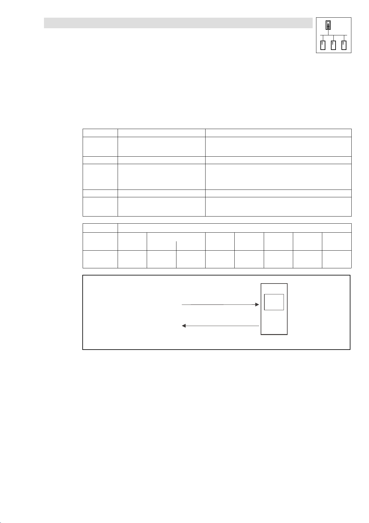
Process data channel 1: CAN1_IO
The CAN1_IO SB can be used for the data exchange of cyclic process data (e. g. setpoints and
actual values) with a higher−level host system.
FIF−CAN
(FIF interface)
For Drive PLC only!
cyclic process data (sync−controlled)
process data channel 1
CANaux
For ECSxA only!
Information
CAN1_IN
CAN1_OUT
Fig. 2−2 Process data channel 1 (CAN1_IO) for the cyclic data exchange
l
PLC−Systembus EN 2.0
Host
2−7
Page 20
System bus (CAN) for Lenze PLC devices
s
General information
Process data channel 2/3: CAN2_IO/CAN3_IO
The SBs CAN2_IO and CAN3_IO are designed for the data exchange of event− or time−controlled
process data among the devices. These SBs can also be used for the data exchange with
decentralised input/output terminals and higher−level host systems.
event−controlled process data
process data channel 2
CAN2_IN
CAN2_OUT
Fig. 2−3 Process data channels 2 and 3 (CAN2_IO/CAN3_IO) for the event− or time−controlled data exchange
CAN2_OUT
CAN2_IN
event−controlled process data
process data channel 3
CAN3_IN
CAN3_OUT
CAN3_OUT
CAN3_IN
E. g. decentralised terminal
Tip!
Detailed information on the CAN1_IO ... CAN3_IO CAN objects integrated in the PLC can be found
in the chapter 7, "CAN system blocks":
CAN1_IO for cyclic process data (sync−controlled)
CAN2_IO for event− or time−controlled process data Chapter 7.4(^ 7−14)
CAN3_IO for event− or time−controlled process data Chapter 7.5(^ 7−17)
9300 Servo PLC:
Drive PLC:
ECSxA:
Chapter 7.1(^ 7−1)
Chapter 7.2(^ 7−6)
Chapter 7.3(^ 7−10)
2−8
PLC−Systembus EN 2.0
l
Page 21
System bus (CAN) for Lenze PLC devices
General information
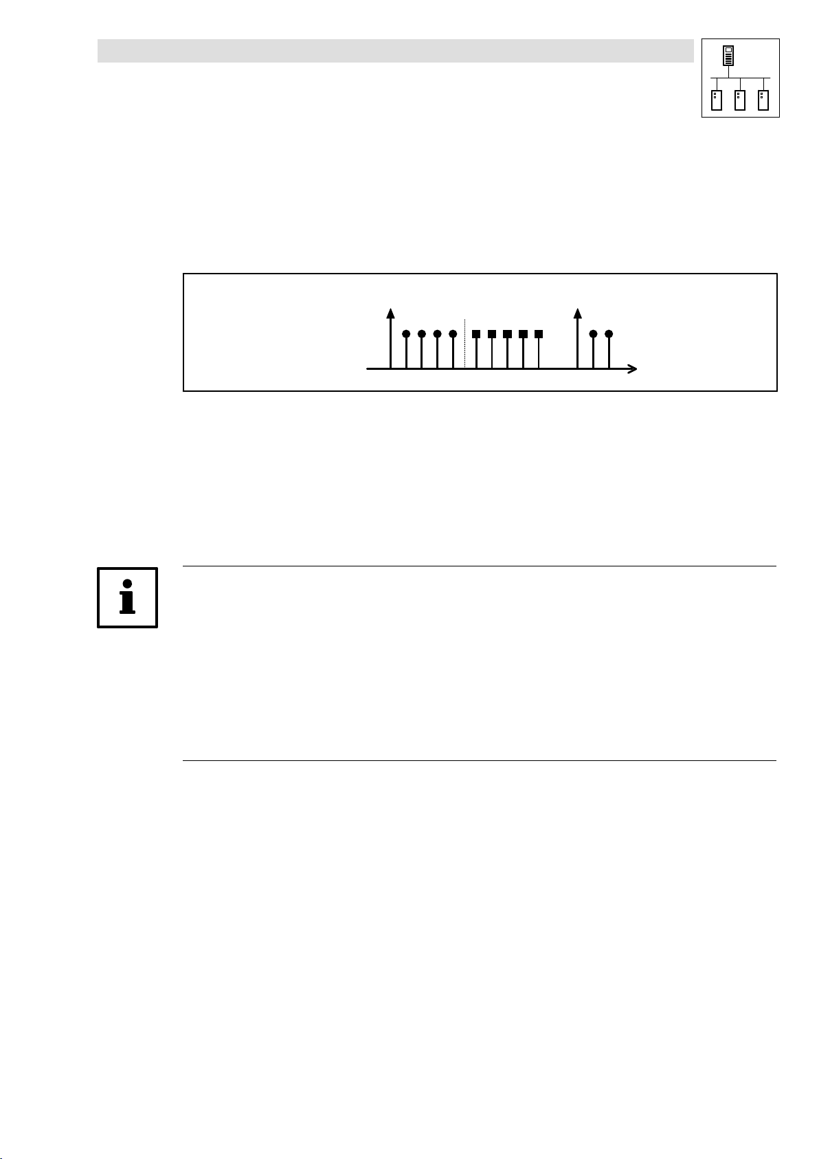
2.6.2 Sync telegram for cyclic process data
For the transmission of cyclic process data, a specific telegram − the sync telegram − is required for
the synchronisation.
The sync telegram which has to be generated by a different node initiates the transmission process
for the cyclic process data of the PLC and at the same time is the trigger point for the data acceptance
of the cyclic process data received in the PLC:
Sync telegram Sync telegram
CAN1_OUT CAN1_IN
1. 2. 3. 4.
Fig. 2−4 Synchronisation of the cyclic process data by a sync telegram (without considering the asynchronous data)
1. After a sync telegram has been received, the cyclic process output data (CAN1_OUT) are sent
by the PLC if "respond to sync" has been activated.
2. When the transmission process has been completed, the cyclic process input data (CAN1_IN)
are received by the PLC.
3. The data acceptance in the PLC is effected with the next sync telegram.
4. All further telegrams (e. g. for parameters or event−controlled process data) are accepted in an
asynchronous manner by the PLC after transmission has been completed.
Tip!
The response to a sync telegram is configured via the following codes:
· for CAN1_OUT via C0366. (^ 3−7)
· for XCAN1_OUT ... XCAN3_OUT via C2375. (^ 4−7)
· for FIF−CAN1_OUT via C2466. (^ 5−7)
· for CANaux1_OUT via C2466. (^ 5−7)
Also the telegrams of CAN2_OUT and CAN3_OUT can be transferred after a sync telegram, the
parameterisation of this function is carried out via the CAN_Management SB.
(^ 7−20)
l
PLC−Systembus EN 2.0
2−9
Page 22

System bus (CAN) for Lenze PLC devices
General information
2.6.3 Process data telegram
The process data telegram is structured as follows:
11bit 8 bytes user data
Identifier Byte 1 Byte 2 Byte 3 Byte 4 Byte 5 Byte 6 Byte 7 Byte 8
Identifier
Information on the identifier can be found in chapter 2.4.1.
User data
The 8 bytes user data received or to be transmitted respectively can be read or written
simultaneously by several variables of different data types.
Detailed information on the user data can be found in the description to the respective system block:
(^ 2−3)
· CAN system blocks (^ 7−1 ff.)
· FIF−CAN system blocks (^ 8−1 ff.)
· CAN−AUX system blocks (^ 9−1 ff.)
2−10
PLC−Systembus EN 2.0
l
Page 23
System bus (CAN) for Lenze PLC devices
2.7 Transmitting parameter data
For Lenze devices, parameter data are the so−called codes.
· Parameter settings for instance are carried out in the case of a one−time setting of the system
during commissioning, or in the case of a material change of the production machine.
· Parameter data are transferred as so−called SDOs (Service Data Objects) via the system bus
and are acknowledged by the receiver, i. e. the transmitter receives a feedback on whether the
transmission was successful.
2.7.1 Parameter data telegram
The telegram for parameter data is structured as follows:
11bit 8 bytes user data
Identifier
Command
code
· In the following subchapters the different components of the telegram are explained in detail.
· An example for writing a parameter can be found in chapter 2.7.2. (^ 2−15)
· An example for reading a parameter can be found in chapter 2.7.3. (^ 2−17)
Index
Low byte High byte
General information
Subindex Data 1 Data 2 Data 3 Data 4
2.7.1.1 Identifier
Identifier
For the transmission of parameter data, two parameter data channels are provided, which are
addressed via the identifier:
SDOs Parameter data channel 1
Parameter data channel 2
Tip!
Between the identifiers for parameter data channels 1 and 2 there respectively is an offset of 64:
· Output of parameter data channel 1 = 1536
· Output of parameter data channel 2 = 1536 + 64 = 1600
Command
code
Output (transmission) 1536 600
Input (reception) 1408 580
Output (transmission) 1600 640
Input (reception) 1472 5C0
Index
Low byte High byte
Identifier = basic identifier + node address of the node
Subindex Data 1 Data 2 Data 3 Data 4
dec hex
+ C0350
+ C2350
+ C2450
+ C0350
+ C2350
+ C2450
(CAN)
(XCAN)
(FIF−CAN/CANaux)
(CAN)
(XCAN)
(FIF−CAN/CANaux)
l
PLC−Systembus EN 2.0
2−11
Page 24

System bus (CAN) for Lenze PLC devices
General information
2.7.1.2 Command code
Identifier
Command
code
Index
Low byte High byte
Subindex Data 1 Data 2 Data 3 Data 4
Among other things, the command code contains the command to be carried out as well as
information on the parameter data length, and is structured as follows:
Bit 7 (MSB) Bit 6 Bit 5 Bit 4 Bit 3 Bit 2 Bit 1 Bit 0
Command Command Specifier (cs) Length e s
Write request 0 0 1 0
Write response 0 1 1 0 0 0
Read request 0 1 0 0 0 0
Read response 0 1 0 0 1 1
Error Response 1 0 0 0 0 0 0 0
00 = 4 bytes
01 = 3 bytes
10 = 2 bytes
11 = 1 byte
1 1
Command code for parameters with 1, 2, or 4 bytes data length:
4 byte data
(32 bit)
Command hex dec hex dec hex dec Information
Write Request 23 35 2B 43 2F 47 Send parameter to a node
Write Response 60 96 60 64 60 96 Node response to "write request" (acknowledgement)
Read Request 40 64 40 64 40 64 Request for reading a parameter of a node
Read Response 43 67 4B 75 4F 79 Response to the read request with an actual value
Error Response 80 128 80 128 80 128 Node reports an error with regard to communication
2 byte data
(16 bit)
1 byte data
(8 bit)
"Error Response" command
In the case of this error, an "Error Response" is generated by the node that is addressed.
· This telegram in data 4 always contains the value "6", and in data 3 an error code:
Error Response command code Data 3 Data 4 Error message
3
80
hex
C0
hex
5 Incorrect subindex
6 Incorrect index
8
6
Access denied
Job was not edited
(for 8200 vector + FIF module)
2−12
PLC−Systembus EN 2.0
l
Page 25
System bus (CAN) for Lenze PLC devices
2.7.1.3 Addressing the parameter (index/subindex)
General information
Identifier
Command
code
Index
Low byte High byte
Subindex Data 1 Data 2 Data 3 Data 4
The addressing of the parameter or of the Lenze code which is to be read or written is effected via
the index of the telegram:
Index + 24575 * Lenze code number
· The value for the index is to be entered divided into a low and a high byte in the left−justified
Intel format (see example).
· If a subcode is to be addressed, enter the number of the respective subcode in the subindex
of the telegram.
· For codes without subcodes, the subindex always receives the value "0".
· The index for Lenze codes is between 40C0
Lenze code Index
C0000 24575 5FFF
... ... ...
C7999 16576 40C0
(16576) and 5FFF
hex
dec hex
(24575).
hex
Tip!
For converting a code number to the corresponding index, the function L_FUNCodeIndexConv in
the LenzeDrive.lib function library is provided to you.
Example:
Subcode 1 of code C0168 (fault messages) is to be addressed:
Index + 24575 * 168 + 24407 + 5F57
11bit 8 bytes user data
Identifier
Command
code
Index
Low byte High byte
57
hex
5Fhex 1
Subindex Data 1 Data 2 Data 3 Data 4
hex
hex
l
PLC−Systembus EN 2.0
2−13
Page 26
System bus (CAN) for Lenze PLC devices
General information
2.7.1.4 Data of the parameter (data 1 ... data 4)
Identifier
Command
code
Index
Low byte High byte
Subindex Data 1 Data 2 Data 3 Data 4
For the data of the parameter up to 4 bytes (data 1 ... data 4) are provided.
· The data are presented in the left−justified Intel format with data 1 as LSB and data 4 as MSB
(see example).
Example:
For a code in the "Fixed32" data format, the value "20" is to be transmitted.
· "Fixed32" is a fixed point format with 4 decimal positions. Therefore the value has to be
multiplied by 10000:
Data
11bit 8 bytes user data
Identifier
Command
code
+ 20 @ 10000 + 200000 + 00 03 0D 40
1...4
Index
Low byte High byte
Subindex Data 1 Data 2 Data 3 Data 4
hex
40
hex
(LSB) (MSB)
0D
hex
03
hex
00
hex
Tip!
The parameters of the Lenze devices are stored in different formats.
Detailed information on this subject can be found in the Manual for the respective PLC in the chapter
"Appendix − Table of attributes".
2−14
PLC−Systembus EN 2.0
l
Page 27
System bus (CAN) for Lenze PLC devices
2.7.2 Writing parameters (example)
Task
The acceleration time (C0012) of the controller with the node address 1 is to be set to 20 s via the
parameter data channel 1.
Telegram to the controller
Formula Information
Identifier = basic identifier + node address
Command code = 23
Index = 24575 − number of the Lenze code
Subindex = 0 · Subcode = 0 (no subcode)
Data 1 ... 4 = 20 x 10000
= 1536 + 1
= 1537
hex
= 24575 − 12
= 24563
= 5F F3
hex
= 200000
= 00 03 0D 40
hex
General information
· Basic identifier for parameter data channel 1 (output) = 1536
· Node address of the controller = 1
· Command "Write Request" (send parameter to controller)
· Code = C0012 (acceleration time)
· Value = 20 s
· Fixed32 data format (4 fixed decimal positions); multiply value by 10000
11bit 8 bytes user data
Identifier
1537 23
Fig. 2−5 Writing parameters
Command
code
hex
Index
Low byte High byte
F3
hex
Write Request
(C0012 = 20 s)
Write Response
5F
hex
Subindex Data 1 Data 2 Data 3 Data 4
0 40
hex
(LSB) (MSB)
0D
hex
03
hex
L
Identifier = 1537
Identifier = 1409
SDO 1 / Node-ID 1
00
hex
l
PLC−Systembus EN 2.0
2−15
Page 28
System bus (CAN) for Lenze PLC devices
General information
Telegram from controller (acknowledgement if carried out correctly)
Formula Information
Identifier = basic identifier + node address
Command code = 60
Index = index of the read request
Subindex = subindex of the read request
Data 1 ... 4 = 0 · Acknowledgement only
11bit 8 bytes user data
Identifier
1409 60
= 1408 + 1
= 1409
hex
Command
code
hex
Index
Low byte High byte
F3
hex
5F
· Basic identifier for parameter data channel 1 (input) = 1408
· Node address of the controller = 1
· "Write Response" command (acknowledgement by the controller)
Subindex Data 1 Data 2 Data 3 Data 4
hex
0 0 0 0 0
2−16
PLC−Systembus EN 2.0
l
Page 29
System bus (CAN) for Lenze PLC devices
2.7.3 Reading a parameter (example)
Task
The heatsink temperature (C0061) of the controller with the node address 5 is to be read via the
parameter data channel 1.
Telegram to the controller
Formula Information
Identifier = basic identifier + node address
Command code = 40
Index = 24575 − number of the Lenze code
Subindex = 0 · Subcode = 0 (no subcode)
Data 1 ... 4 = 0 · Read request only
= 1536 + 5
= 1541
hex
= 24575 − 61
= 24514
= 5F C2
hex
General information
· Basic identifier for parameter data channel 1 (output) = 1536
· Node address of the controller = 5
· Command "Read Request" (request to read a parameter from the
controller)
· Code = C0061 (heatsink temperature)
11bit 8 bytes user data
Identifier
1541 40
Fig. 2−6 Reading parameters
Command
code
hex
Index
Low byte High byte
C2
hex
Read Request
(C0061 = ???)
Read Response
(C0061 = 43 ºC)
5F
hex
Subindex Data 1 Data 2 Data 3 Data 4
0 0 0 0 0
L
Identifier = 1541
Identifier = 1413
SDO 1 / Node-ID 5
l
PLC−Systembus EN 2.0
2−17
Page 30
System bus (CAN) for Lenze PLC devices
General information
Telegram from the controller (value of the parameter requested)
Formula Information
Identifier = basic identifier + node address
Command code = 43
Index = index of the read request
Subindex = subindex of the read request
Data 1 ... 4 = 43 x 10000
11bit 8 bytes user data
Identifier
1413 43
= 1408 + 5
= 1413
hex
= 430000
= 00 06 8F B0
Command
code
hex
hex
Index
Low byte High byte
C2
hex
5F
· Basic identifier for parameter data channel 1 (input) = 1408
· Node address of the controller = 5
· "Read Response" command (response to the read request with the
current value)
· Assumption: The current heatsink temperature of the controller is 43 ºC,
therefore the value of the parameter to be read is 43
· Fixed32 data format (4 fixed decimal positions); multiply value by 10000
Subindex Data 1 Data 2 Data 3 Data 4
hex
0 B0hex 8Fhex 06
hex
00
hex
(LSB) (MSB)
2−18
PLC−Systembus EN 2.0
l
Page 31
System bus (CAN) for Lenze PLC devices
2.8 Free CAN objects
If many nodes are connected to the system bus (CAN), it may occur that the CAN objects
(CAN1_IO ... CAN3_IO) which are fixedly integrated in the PLC are not sufficient for the
communication intended, and further CAN objects are required.
By using the functions/function blocks of the LenzeCanDrv.lib function library, so−called "free CAN
objects" can be added to the fixedly integrated CAN objects.
Characteristics of the free CAN objects
Free CAN objects
User data per object 1 ... 8 byte
Intended use Transmission of parameter and process data
Transmission modes · Event−controlled transmission
· Time−controlled transmission
· Time−controlled transmission with superimposed event control
· Forced transmission
Range for identifiers Transmission and reception identifiers can be allocated in the range of 0 ... 2047, but they have to differ from the
identifiers of the integrated CAN objects.
General information
(^ 10−2)
Note!
The free CAN objects are processed via a so−called transmit request memory by the operating
system, i. e. the transmission process is not carried out immediately when the L_CanPdoTransmit
FB is called, but is effected in a delayed manner.
The transmission and reception jobs of the free CAN objects are not linked to the process image.
(^ 10−8)
l
PLC−Systembus EN 2.0
2−19
Page 32

System bus (CAN) for Lenze PLC devices
General information
2.9 Application recommendations for the different CAN objects
The following table provides a comparison of the different CAN objects and their specific
characteristics:
CAN object Process data
CAN1_IO Þ Þ Þ
CAN2_IO Þ Þ
CAN3_IO Þ Þ
XCAN1_IO Þ Þ Þ
XCAN2_IO Þ Þ
XCAN3_IO Þ Þ
FIF_CAN1_IO Þ Þ Þ
FIF_CAN2_IO Þ Þ
FIF_CAN3_IO Þ Þ
CANaux1_IO Þ Þ Þ
CANaux2_IO Þ Þ
CANaux3_IO Þ Þ
Free CAN objects Þ Data exchange
1)
Sync telegram required for the function of the respective CAN1 object
transmission
Linked to the
process image
Sync telegram
required
1)
Application recommendation
Data exchange
· of position setpoints/actual values
· of speed setpoints for servo applications
· of setpoints/actual values
· with analog terminal I/Os
2−20
PLC−Systembus EN 2.0
l
Page 33

System bus (CAN) for Lenze PLC devices
2.10 Monitoring mechanisms
In the CANopen communication profile (CiA DS301, version 4.01) two optional monitoring
mechanisms for ensuring the function of system bus nodes are specified, "Heartbeat" and "Node
Guarding".
Note!
The "Heartbeat" and "Node Guarding" monitoring mechanisms are supported by the
9300 Servo PLC, Drive, PLC and by the ECSxA axis module as of V6.0.
The initialisation and execution of the monitoring mechanisms is carried out by means of the
functions/function blocks of the LenzeCanDSxDrv.lib function library.
2.10.1 "Heartbeat"
General information
(^ 11−1)
The "Heartbeat" monitoring mechanism is a Producer−Consumer−oriented method which does not
require an enquiry message and where each node is able to monitor the state of all other nodes.
Heartbeat Producer Heartbeat Consumer(s)
s
s
Stopped
Operational
Pre-Operational
Boot-Up Event
Heartbeat
Producer
Time
Request
Request
r
r
r:
reserved
s: State of the heartbeat producer:
4
5
127
0
18
Indication(s)
Heartbeat
Consumer
Time
18
Indication(s)
Heartbeat
Event
Fig. 2−7 "Heartbeat" monitoring mechanism
· A node (Producer) signalises its communication status by cyclically transmitting a so−called
"Heartbeat" message.
· This "Heartbeat" message can be received by one, several, or by all the other nodes
(Consumer), and thus they can monitor the respective node.
· If the responsible, monitoring node (Consumer) does not receive the "Heartbeat" message
from the node to be monitored (Producer) within the set monitoring time
(HeartBeatConsumerTime), a "Heartbeat" event is displayed in its application.
l
PLC−Systembus EN 2.0
2−21
Page 34

System bus (CAN) for Lenze PLC devices
General information
2.10.2 "Node Guarding"
In contrast to the "Heartbeat" monitoring mechanism, for the "Node Guarding" an enquiry message
from the monitoring node (NMT Master) is required.
NMT Master NMT Slave
RTR
Request
Node
Guard
Time
Node
Life
Time
Fig. 2−8 "Node guarding" monitoring mechanism
Confirmation
Request
Confirmation
Node
Guarding
Event
· The NMT master monitors each of the nodes to be monitored (NMT slave) cyclically using a
node−specific "Remote Transmission Request" telegram.
· The NMT slave to be monitored returns its communication status as a response to this
request.
· If the NMT master does not receive the message from the NMT Slave) to be monitored within
the set monitoring time (NodeLifeTime|, a "Node Guarding" event is displayed in its
application.
· For the NMT slave to be monitored, however, a "Life Guarding" event is activated if its status
has not been enquired by the monitoring NMT master for longer than its "Node Life Time".
t
RTR
t
t:
Toggle bit
s: NMT Slave state:
Stopped
4
Operational
5
Pre-Operational
127
Boot-Up Event
0
18
Indication
s
Response
Node
Life
Time
18
Indication
s
Response
Life
Guarding
Event
2−22
PLC−Systembus EN 2.0
l
Page 35

System bus (CAN) for Lenze PLC devices
"CAN" system bus interface configuration
3 Configuration (system bus − CAN interface)
Tip!
Changes with regard to the CAN baud rate, the CAN addresses, and the identifiers for PDOs only
are accepted after a reset node.
A reset node can be effected by
· Reconnection of the mains
· Reset node command via NMT command. (^ 2−6)
· Reset node via C0358 (^ 3−8)
3.1 CAN baud rate
In order to accomplish communication via the system bus, all nodes have to use the same baud rate
for data transmission.
· The configuration of the baud rate is effected via code C0351:
Code LCD
C0351 CAN baud rate 0 0 500 kbit/s
Possible settings
Lenze Selection
1 250 kbit/s
2 125 kbit/s
3 50 kbit/s
4 1000 kbit/s
Information
System bus − baud rate
· Save changes with C0003 = 1.
· Changes are only valid after
reset node!
l
PLC−Systembus EN 2.0
3−1
Page 36

System bus (CAN) for Lenze PLC devices
"CAN" system bus interface configuration
3.2 CAN boot−up
If the initialisation of the system bus and the associated state change from Pre−operational to
Operational is not taken over by a higher−level master system, the PLC or a controller can be
designated as a "quasi" master to accomplish this task.
· The configuration is effected via code C0352:
Code LCD
C0352 CAN mst 0 0 Boot−up not active
Possible settings
Lenze Selection
1 Boot−up active
Information
Device sends system bus boot−up
and thus is the "quasi" master.
Delay time for system bus initialisation (boot−up)
Some nodes (e. g. HMIs) require a specific starting time after mains connection before they can be
transferred to the Operational state via NMT commands by the master.
In order to ensure that even the node with the greatest starting time really is ready to receive NMT
commands, you can set a delay time. When it has expired, NMT commands can only be transmitted
after mains power−up.
· The configuration of this delay time is effected via code C0356/1:
Code LCD
C03561CAN boot−up
Possible settings
Lenze Selection
0 {1 ms} 65000 Delay time after power−on for
3000
Information
initialisation via the "quasi" master
3−2
PLC−Systembus EN 2.0
l
Page 37

System bus (CAN) for Lenze PLC devices
3.3 Node address (node ID)
Assign a node address − also called Node ID − within the range of 1 to 63 to each node within the
system bus network as a definite identification.
· The same node address may not be assigned more than once within the network.
· The configuration of the node address for the PLC is carried out via code C0350:
"CAN" system bus interface configuration
Code LCD
C0350 CAN address 1 1 {1} 63 System bus − node address
Possible settings
Lenze Selection
Allocation of the node address for the data exchange among Lenze devices
If Lenze devices are provided with node addresses in a consistent ascending order, the identifiers
of the event−controlled data objects (CAN2_IO/CAN3_IO) are set in way by the factory which enables
a communication from one device to the other:
L
CAN2_OUT
CAN3_OUT
Node-ID 1
Fig. 3−1 Data exchange among Lenze devices
CAN2_IN
CAN3_IN
L
Node-ID 2
CAN2_OUT
CAN3_OUT
Information
· Save changes with C0003 = 1.
· Changes are only valid after
reset node!
L
CAN2_IN
CAN3_IN
Node-ID 3
l
PLC−Systembus EN 2.0
3−3
Page 38

System bus (CAN) for Lenze PLC devices
"CAN" system bus interface configuration
3.4 Identifiers of the process data objects
The identifiers for the CAN1_IO ... CAN3_IO process data objects are generated by the so−called
basic identifier and the node address set in C0350:
Identifier + basic identifier ) node address
PDOs CAN1_IO (cyclic process data)
CAN2_IO (event− or time−controlled process data)
CAN3_IO (event− or time−controlled process data)
Basic identifiers
dec hex
CAN1_IN 512 200
CAN1_OUT 384 180
CAN2_IN 640 280
CAN2_OUT 641 281
CAN3_IN 768 300
CAN3_OUT 769 301
3.4.1 Allocation of individual identifiers
For greater system bus networks with many nodes it may be reasonable to set individual identifiers
for the CAN1_IO ... CAN3_IO process data objects via C0353/C0354, which are independent of the
node address set in C0350:
1. Set C0353/x to "1".
– (x = subcode of the corresponding process data object):
Code LCD
C0353 CAN addr sel 0 Identifier assignment under C0350 + basic
1 CAN addr sel1 0 CAN1_IN/OUT
2 CAN addr sel2 0 CAN2_IN/OUT
3 CAN addr sel3 0 CAN3_IN/OUT
2. Set the value which added to "384" makes the desired identifier in C0354/x.
– (x = subcode of the corresponding process data object):
Code LCD
C0354 CAN addr 1 {1} 512 Specification of individual
1
IN1 addr2
2
OUT1 addr2
3
IN2 addr2
4
OUT2 addr2
5
IN3 addr2
6
OUT3 addr2
Possible settings
Lenze Selection
identifier
1 Identifier assignment under C0354/x
Possible settings
Lenze Selection
129
1
257
258
385
386
Information
Source for the identifiers of the
process data objects
· Save changes with C0003 = 1.
· Changes are only valid after
reset node!
Information
identifiers for the process data
objects
CAN1_IN
CAN1_OUT
CAN2_IN
CAN2_OUT
CAN3_IN
CAN3_OUT
3−4
PLC−Systembus EN 2.0
l
Page 39

System bus (CAN) for Lenze PLC devices
"CAN" system bus interface configuration
· Please note that the identifier of the telegram to be transmitted has to comply with the
identifier of the process data input object to be activated.
· In the case of an individual address allocation, the identifier for the process data objects is
composed as follows:
Identifier + 384 ) value of C0354/x
· Thus, identifiers in the range of 385 ... 896 can be allocated for the process data objects.
3.4.2 Display of the identifier set
Via C0355 you can have the identifier displayed which is set for the process data objects.
· C0355 is a display code, settings cannot be carried out via C0355.
Code LCD
C0355
CAN Id
1
CAN1_IN Id
2
CAN1_OUT Id
3
CAN2_IN Id
4
CAN2_OUT Id
5
CAN3_IN Id
6
CAN3_OUT Id
Possible settings
Lenze Selection
385 {1} 896 System bus identifier
g
x = subcode
Information
for the process data objects
CAN1_IN
CAN1_OUT
CAN2_IN
CAN2_OUT
CAN3_IN
CAN3_OUT
l
PLC−Systembus EN 2.0
3−5
Page 40

System bus (CAN) for Lenze PLC devices
"CAN" system bus interface configuration
3.5 Cycle time (CAN2_OUT/CAN3_OUT)
The transmission of the output data of CAN2_OUT and CAN3_OUT can be carried out in an
event−controlled or time−controlled manner.
· The configuration of the transmission mode is effected via code C0356/x:
Code LCD
C0356
2
CAN2_OUT T
3
CAN3_OUT T
Possible settings
Lenze Selection
0 {1} 65000
0 = event−controlled transmission
0
0
Information
Factor to the task time for
transmitting the process data
object
Event−controlled transmission
C0356/x = 0
· The transmission of the output data is always effected if a value has changed within the
8 bytes of user data (Lenze setting).
Time−controlled transmission
C0356/x = 1 ... 65000
· The transmission of the output data is effected within the cycle time set in C0356/x (relating to
the task cycle time).
Example:
· The CAN object is used in a 10 ms task.
· Factor set via C0356/2 = 5
ð The CAN object is transmitted after every fifth cycle of the task, i. e. every 50 ms (10 ms x 5).
3.6 Delay time (CAN2_OUT/CAN3_OUT)
For the transmission of the output data of CAN2_OUT and CAN3_OUT a delay time can be configured
via code C0356/4:
Code LCD
C0356
4
CAN delay 20
If the NMT state Operational (to Pre−operational or Stopped) is reached, the "CANdelay" delay time
is started. After the delay time has expired, the PDOs CAN−OUT2 and CAN−OUT3 are transmitted
for the first time.
Possible settings
Lenze Selection
0 {1 ms} 65000 Delay time for sending the process
Information
data object.
3−6
PLC−Systembus EN 2.0
l
Page 41

System bus (CAN) for Lenze PLC devices
3.7 Synchronisation
Tip!
By means of the CAN_Synchronization SB, the internal time base of the PLC can be synchronised
with the arrival of the sync telegram.
Thus, the internal calculating processes (e. g. control−oriented processes) of the PLC can be
synchronised with the calculating processes of other nodes which can also process the sync
telegram.
Detailed information on the CAN_Synchronization SB can be found in chapter 7.7.
3.7.1 CAN sync response
The response to the reception of a sync telegram can be configured via C0366:
"CAN" system bus interface configuration
(^ 7−23)
Code LCD
C0366 Sync response 1 CAN sync response
Possible settings
Lenze Selection
0 No response No response
1 Response to sync PLC responds to a sync telegram
3.7.2 CAN sync identifiers
The transmission or reception identifiers of the sync telegram can be configured via C0367/C0368:
Code LCD
C0367 Sync Rx Id 128 1 {1} 256 CAN sync Rx identifier
C0368 Sync Tx Id 128 1 {1} 256 CAN sync Tx identifier
Possible settings
Lenze Selection
3.7.3 CAN sync Tx transmission cycle
The cycle time within which a sync telegram with the identifier set in C0368 is transmitted can be
configured via C0369:
IMPORTANT
by sending the CAN1_OUT object.
IMPORTANT
Receive identifier of the sync
telegram
Transmit identifier of the sync
telegram
l
Code LCD
C0369 Sync Tx time 0 0 {1} 65000
Possible settings
Lenze Selection
0 = Off
PLC−Systembus EN 2.0
IMPORTANT
CAN sync transmission telegram
cycle
A sync telegram with the identifier
of C0368 is sent with the set cycle
time.
3−7
Page 42

System bus (CAN) for Lenze PLC devices
"CAN" system bus interface configuration
3.8 Reset node
Changes with regard to the CAN baud rate, the node addresses and the identifiers only are accepted
after a reset node.
A reset node can be effected by
· Reconnection of the mains
· Reset node command via NMT command. (^ 2−6)
· Reset node command via the CAN_Management SB (^ 7−20)
· Reset node via C0358:
Code LCD
C0358 Reset node 0 0 No function
Possible settings
Lenze Selection
1 CAN reset node
3.9 System bus management
Via the CAN_Management SB,
· a reset node can be activated.
· "Communication error" and "Bus off state" can be processed in the PLC program.
· the instant of transmission of CAN2_OUT and CAN3_OUT can be influenced.
Tip!
Detailed information on the CAN_Management SB can be found in chapter 7.6. (^ 7−20)
3.10 Mapping indexes to codes
The operating system as of V6.0 of the Lenze PLCs contains a specific CanDSx driver which can be
activated using the functions of the LenzeCanDSxDrv.lib function library.
By means of this driver indexes within the PLC can be assigned to another code as the one which
is automatically allocated.
Information
Reset node
(^ 11−1)
3−8
Notes!
· Each Lenze code is fixedly assigned to an index via the following formula:
Index = 5FFF
Index = 24575
· The function of the CanDSx driver only is limited to the system bus (CAN).
– For the second FIF−CAN channel provided for the drive PLC, the CanDSx driver cannot be
used!
− code
hex
− code
dec
PLC−Systembus EN 2.0
l
Page 43

System bus (CAN) for Lenze PLC devices
"CAN" system bus interface configuration
3.10.1 Functional principle considering as example
Task
Within the PLC, a function has been realised from the user side, which can be parameterised via the
user code C3200/5. The index 21375
Index = 24575
dec
On the basis of the communication profile used, this function, however, is to be parameterisable via
the index 4101
/subindex 2 instead.
dec
Solution
is automatically assigned to code C3200:
dec
− code = 24575
− 3200 = 21375
dec
dec
Via the functions of the LenzeCanDSxDrv.lib function library, index 4101
/subindex 2 is simply
dec
diverted to code C3200/5 within the PLC, so that the communication profile can be used unchanged.
Functional principle
The operating system (as of V6.0) of the Lenze PLCs contains a so−called "mapping table". With this
table up to 256 indexes within the PLC can be "mapped" to other codes than to those which are
automatically allocated.
If a CAN telegram arrives and the index is in the valid range, it is checked whether this index is listed
in the mapping table.
· If the index is listed in the mapping table, the code which has been newly assigned to this
index in the mapping table is accessed.
·
If the index is not listed in the mapping table, the code which is automatically allocated is
accessed, resulting from the above−mentioned formula.
Index access: 4101/2
SDO telegram
Index number
valid ?
Index access: 21475/1
SDO telegram
Index number
valid ?
yes
Mapping table
CAN index Lenze code Lenze subcode
4101
4101
20000 0
Fig. 3−2 Process of diverting indexes to codes
CAN subindex
1
2 3200 5
Code access: C3200/5
l
3200
3000
4
0
PLC−Systembus EN 2.0
yes
Mapping table
CAN index Lenze code Lenze subcode
4101
4101
20000 0
CAN subindex
1
2 3200 5
Lenze code = 24575 - Index = 24575 - 21475 = 3100
Code access = C3100/1
3200
3000
4
0
3−9
Page 44

System bus (CAN) for Lenze PLC devices
"CAN" system bus interface configuration
3.11 Remote parameterisation (gateway function)
The drive PLC, 9300 Servo PLC, and the ECSxA axis module as of the V6.x operating system support
the remote parameterisation of other system bus nodes. All write/read accesses to parameters then
are no more carried out in the PLC, but are diverted to the node selected for remote maintenance.
· The diversion is effected via the SDO1 parameter data channel of the node selected.
· The node which the diversion of the write/read accesses is to be effected to is defined via
C0370 by setting the node address of the corresponding node here:
Code LCD
C0370 Gateway addr. 0 System bus: Activate remote
Possible settings
Lenze Selection
0 {1} 63
0 = remote parameter setting deactivated
Information
parameter setting
· A timeout during remote parameterisation actuates the system error message CE5; the
response to this can be configured via C0603.
Example
(^ 3−12)
· The system bus node with the node address 5 has been selected for the remote
parameterisation (C0370 = 5).
· A write access to code C0011 is carried out, it is diverted to the selected system bus node via
the system bus:
C0011 = 3005 rpm
L
System bus
C0370 = 5
Node-ID 1
"9300 Servo PLC"
Node-ID 3
"8200 vector"
Fig. 3−3 Remote parameterisation (gateway function)
3−10
PLC−Systembus EN 2.0
L L
Node-ID 9
"Drive PLC"
L
C0011
Node-ID 5
"9300 Servo PLC"
l
Page 45

System bus (CAN) for Lenze PLC devices
"CAN" system bus interface configuration
3.12 Monitoring processes
3.12.1 Time monitoring for CAN1_IN ... CAN3_IN
For the inputs of the CAN1_IN ... CAN3_IN process data objects a time monitoring can be configured
via C0357:
Code LCD
C0357
1
CE1monit time
2
CE2monit time
3
CE3monit time
The response for the case that no telegram has been received within the defined monitoring time can
be configured via codes C0591 ... C0593:
Code LCD
C0591 MONIT CE1 3 0 TRIP
C0592 MONIT CE2 3 0 TRIP
C0593 MONIT CE3 3 0 TRIP
3.12.2 Bus−off
If the PLC has disconnected from the system bus due to too many incorrectly received telegrams,
the signal "BusOffState" (CE4) is set.
The response to this can be configured via C0595:
Possible settings
Lenze Selection
0 {1 ms} 65000 Monitoring time for process data
3000
3000
3000
Possible settings
Lenze Selection
2 Warning
3 Off
2 Warning
3 Off
2 Warning
3 Off
Information
input objects
Information
Configuration of the monitoring for
CAN1_IN error "CommErrCANIN1"
(CAN1 CE1)
Configuration of the monitoring for
CAN2_IN error "CommErrCANIN2"
(CAN2 CE2)
Configuration of the monitoring for
CAN3_IN error "CommErrCANIN3"
(CAN3 CE3)
Code LCD
C0595 MONIT CE4 3 0 TRIP
Possible settings
Lenze Selection
2 Warning
3 Off
Information
Configuration of the monitoring for
"BusOffState" (CE4)
Tip!
Possible causes for incorrectly received telegrams can be:
· Missing bus termination
· Non−sufficient shielding
· Differences in potential with regard to the earth connection of the control electronics
· Bus load too high
l
PLC−Systembus EN 2.0
3−11
Page 46

System bus (CAN) for Lenze PLC devices
"CAN" system bus interface configuration
3.12.3 Time−out when remote parameterisation is activated
If a time−out occurs during the remote parameterisation (gateway function) activated via C0370, the
system error message CE5 is output.
The response to this can be configured via C0603:
Code LCD
C0603 MONIT CE5 3 System bus: Monitoring
Possible settings
Lenze Selection
0 TRIP
2 Warning
3 Off
3.12.4 Response in the case of system bus fault messages
Overview of the system bus error sources registered by the PLC and of the possible settings for the
corresponding response:
Fault message Possible settings/response
Display Error
CE1 62 CAN1_IN communication error
CE2 63 CAN2_IN communication error
CE3 64 CAN3_IN communication error
CE4 65 BUS−OFF state
CE5 66 CAN time−out
Meaning TRIP Message Warning Fault/QSPOff Code
No.
ü − ü − • C0591
(time monitoring can be set via C0357/1)
ü − ü − • C0592
(time monitoring can be set via C0357/2)
ü − ü − • C0593
(time monitoring can be set via C0357/3)
ü − ü − • C0595
(too many faulty telegrams were received)
ü − ü − • C0603
(gateway function C0370)
• Lenze setting
ü Possible
− Not possible
Information
configuration
Time−out when remote
parameterisation is activated
(C0370)
3−12
PLC−Systembus EN 2.0
l
Page 47

System bus (CAN) for Lenze PLC devices
"CAN" system bus interface configuration
3.13 Diagnostics
The following codes can be used for diagnostics purposes:
Code Information displayed Information
C0359 Operating status of the system bus Chapter 3.13.1 ^ 3−13
C0360 Number of the telegrams sent and received Chapter 3.13.2 ^ 3−14
C0361 Bus load (in %) Chapter 3.13.3 ^ 3−15
· Settings cannot be carried out via these codes.
3.13.1 Operating status of the CAN interface
Via C0359 you can have the operating status of the system bus displayed:
Code LCD
C0359 CAN state
C0359 Operating status Information
0 Operational The system bus is fully functional. The PLC can transmit and receive parameter and process data.
1 Pre−operational The PLC can transmit and receive parameter data. Process data, however, are ignored.
2 Warning The PLC has received faulty telegrams and is only involved in the system bus passively, i. e. no data can be
3 Bus−off The PLC has disconnected from the system bus due to too many faultily received telegrams.
Possible settings
Lenze Selection
0 Operational
g
1 Pre−operational
2 Warning
3 Bus off
A status change from Pre−operational to Operational can be effected by:
· the CAN master ^ 3−2
· a reset node
– via C0358, if the PLC has been configured as a "quasi" master. ^ 3−8
– via the binary input signal "reset node" at the CAN_Management SB ^ 7−20
sent from the PLC anymore.
Possible causes:
· Missing bus termination
· Non−sufficient shielding
· Differences in potential with regard to the earth connection of the control electronics
· Bus load too high
· PLC is not connected to the system bus.
· The response to this status can be configured via C0595. ^ 3−11
Information
System bus status
l
PLC−Systembus EN 2.0
3−13
Page 48

System bus (CAN) for Lenze PLC devices
"CAN" system bus interface configuration
3.13.2 Telegram counter
Via C0360 you can have the number of the telegrams sent and received by the PLC via
CAN1_IO ... CAN3_IO displayed.
· Only the telegrams which are valid for the PLC are counted.
· Each transmit and receive channel is evaluated separately.
· The max. counter content is 65535 (16 bit); if this value is exceeded, the corresponding
counter starts with 0 again.
Code LCD
C0360 CAN message
1 Message OUT All sent
2 Message IN All received
3 Message OUT1 Sent on CAN_OUT1
4 Message OUT2 Sent on CAN_OUT2
5 Message OUT3 Sent on CAN_OUT3
6 Message POUT1 Sent on parameter data channel 1
7 Message POUT2 Sent on parameter data channel 2
8 Message IN1 Received from CAN_IN1
9 Message IN2 Received from CAN_IN2
10 Message IN3 Received from CAN_IN3
11 Message PIN1 Received from parameter data
12 Message PIN2 Received from parameter data
Possible settings
Lenze Selection
0 {1} 65535 System bus telegram counter
g
Information
(number of telegrams)
· For values > 65535 counting
restarts with 0.
channel 1
channel 2
3−14
PLC−Systembus EN 2.0
l
Page 49

System bus (CAN) for Lenze PLC devices
3.13.3 Bus load by the PLC
Via C0361 you can receive a percentage display of the extent to which the system bus is loaded by
the telegrams of the PLC.
· Only valid telegrams are considered.
· Each transmit and receive channel is evaluated separately.
"CAN" system bus interface configuration
Code LCD
C0361 Load IN/OUT
1 Load OUT All sent
2 Load IN All received
3 Load OUT1 Sent on CAN_OUT1
4 Load OUT2 Sent on CAN_OUT2
5 Load OUT3 Sent on CAN_OUT3
6 Load POUT1 Sent on parameter data channel 1
7 Load POUT2 Sent on parameter data channel 2
8 Load IN1 Received from CAN_IN1
9 Load IN2 Received from CAN_IN2
10 Load IN3 Received from CAN_IN3
11 Load PIN1 Received from parameter data
12 Load PIN2 Received from parameter data
Possible settings
Lenze Selection
0 {1 %} 100 System bus − bus load
g
Information
· Trouble−free operation demands
channel 1
channel 2
that the total bus load (all
connected devices) does not
exceed 80 %.
Limits of the data transmission
Data transmission is limited by the number of telegrams per time unit and by the data transmission
speed.
· For a data exchange within a drive system only consisting of Lenze controllers/PLCs, these
limits can be determined by adding code C0361/1 of all devices involved.
· Example: Three controllers are connected to each other via the system bus:
l
Value of C0361/1 on controller 1: 23.5 % bus load
Value of C0361/1 on controller 2: 12.6 % bus load
Value of C0361/1 on controller 3: 16.0 % bus load
52.1 % total bus load
Tip!
· The bus load of all devices involved should not exceed 80 %.
· If other devices, like for example decentralised inputs and outputs are connected, these
telegrams are to be considered also.
· A bus overload for instance can be effected by an event−controlled transmission of continually
changing signals.
– Remedy: Accordingly alter the setting of the cycle time for CAN2_OUT or CAN3_OUT, so
that the total of all bus loads does not exceed the value of 80 %.
PLC−Systembus EN 2.0
(^ 3−6)
3−15
Page 50

System bus (CAN) for Lenze PLC devices
"CAN" system bus interface configuration
3−16
PLC−Systembus EN 2.0
l
Page 51

System bus (CAN) for Lenze PLC devices
4 Configuration (AIF interface)
By means of an according fieldbus module (e. g. 2175) you can use the AIF interface of the 9300
Servo PLC, drive PLC and of the ECSxA axis module as an additional system bus interface.
Note!
If the fieldbus module attached to the AIF interface and the integrated system bus interface are
connected to the same system bus network, please be absolutely sure that different CAN
addresses as well as different identifiers have been set for the interfaces!
Tip!
Changes with regard to the CAN baud rate, the CAN addresses, and the identifiers for PDOs only
are accepted after a reset node.
A reset node can be effected by
· Reconnection of the mains
· Reset node command via NMT command (^ 2−6)
· Reset node via C0358 (^ 3−8)
Configuration (AIF interface)
4.1 CAN baud rate
In order to accomplish communication via the system bus, all nodes have to use the same baud rate
for data transmission.
· The configuration of the baud rate is effected via code C2351:
Code LCD
C2351 XCAN baud rate 0 0 500 kbit/s
Possible settings
Lenze Selection
1 250 kbit/s
2 125 kbit/s
3 50 kbit/s
4 1000 kbit/s
5 20 kbit/s (not for ECSxA!)
6 10 kbit/s (not for ECSxA!)
Information
System bus − baud rate
· Save changes with C0003 = 1.
· Changes are only valid after
reset node!
l
PLC−Systembus EN 2.0
4−1
Page 52

System bus (CAN) for Lenze PLC devices
Configuration (AIF interface)
4.2 CAN boot−up
If the initialisation of the system bus and the associated state change of Pre−operational to
Operational is not taken over by a higher−level master system, the PLC or a controller can be
designated as a "quasi" master to accomplish this task.
· The configuration is effected via code C2352:
Code LCD
C2352 XCAN mst 0 0 Boot−up not active
Possible settings
Lenze Selection
1 Boot−up active
Information
Device sends system bus boot−up
and thus is the "quasi" master.
Delay time for system bus initialisation (boot−up)
Some nodes (e. g. HMIs) require a specific starting time after mains connection before they can be
transferred to the Operational state via NMT commands by the master.
In order to ensure that even the node with the greatest starting time really is ready to receive NMT
commands, you can set a delay time. When it has expired, NMT commands can only be transmitted
after mains power−up.
· The configuration of this delay time is effected via code C2356/1:
Code LCD
C2356/1 XCAN boot−up 3000 0 {1 ms} 65000 Delay time after power−on for
Possible settings
Lenze Selection
Information
initialisation via the "quasi" master
4−2
PLC−Systembus EN 2.0
l
Page 53

System bus (CAN) for Lenze PLC devices
4.3 Node address (node ID)
Assign a node address − also called Node ID − within the range of 1 to 63 to each node within the
system bus network as a definite identification.
· The same node address may not be allocated more than once within the network.
· The configuration of the node address for the AIF interface of the PLC is effected via code
C2350:
Configuration (AIF interface)
Code LCD
C2350 XCAN address 1 1 {1} 63 System bus − node address
Possible settings
Lenze Selection
Allocation of the node address for the data exchange among Lenze devices
If Lenze devices are provided with node addresses in a consistent ascending order, the identifiers
of the event−controlled data objects (XCAN2_IO/XCAN3_IO) are set in way by the factory which
enables a communication from one device to the other:
L
XCAN2_OUT
XCAN3_OUT
Node-ID 1
Fig. 4−1 Data exchange among Lenze devices
XCAN2_IN
XCAN3_IN
L
Node-ID 2
XCAN2_OUT
XCAN3_OUT
Information
· Save changes with C0003 = 1.
· Changes are only valid after
reset node!
L
XCAN2_IN
XCAN3_IN
Node-ID 3
l
PLC−Systembus EN 2.0
4−3
Page 54

System bus (CAN) for Lenze PLC devices
Configuration (AIF interface)
4.4 Identifiers of the process data objects
The identifiers for the XCAN1_IO ... XCAN3_IO process data objects are generated by the so−called
basic identifier and the node address set in C2350:
Identifier + basic identifier ) node address
PDOs XCAN1_IO (cyclic process data)
XCAN2_IO (event− or time−controlled process data)
XCAN3_IO (event− or time−controlled process data)
Basic identifiers
dec hex
XCAN1_IN 512 200
XCAN1_OUT 384 180
XCAN2_IN 640 280
XCAN2_OUT 641 281
XCAN3_IN 768 300
XCAN3_OUT 769 301
4.4.1 Allocation of individual identifiers
For greater system bus networks with many nodes it can be reasonable to set individual identifiers
for the XCAN1_IO ... XCAN3_IO process data objects via C2353/C2354, which are independent of
the node address set in C2350:
1. Set C2353/x to "1".
– (x = subcode of the corresponding process data object):
Code LCD
C2353 XCAN addr sel 0 Identifier assignment via C2350 + basic
1 XCAN addr sel1 0 XCAN1_IN/OUT
2 XCAN addr sel2 0 XCAN2_IN/OUT
3 XCAN addr sel3 0 XCAN3_IN/OUT
2. Set the value which added to "384" makes the desired identifier in C2354/x.
– (x = subcode of the corresponding process data object):
Code LCD
C2354 XCAN addr 0 {1} 1663 Specification of individual
1
IN1 addr2
2
OUT1 addr2
3
IN2 addr2
4
OUT2 addr2
5
IN3 addr2
6
OUT3 addr2
Possible settings
Lenze Selection
identifier
1 Identifier assignment via C2354/x
Possible settings
Lenze Selection
129
1
257
258
385
386
Information
Source for the identifiers of the
process data objects
· Save changes with C0003 = 1.
· Changes are only valid after
reset node!
Information
identifiers for the process data
objects
XCAN1_IN
XCAN1_OUT
XCAN2_IN
XCAN2_OUT
XCAN3_IN
XCAN3_OUT
4−4
PLC−Systembus EN 2.0
l
Page 55

System bus (CAN) for Lenze PLC devices
Configuration (AIF interface)
· Please note that the identifier of the telegram to be transmitted has to comply with the
identifier of the process data input object to be activated.
· In the case of an individual address allocation, the identifier for the process data objects is
composed as follows:
Identifier + 384 ) value of C2354/x
· Thus, identifiers in the range of 384 ... 2047 can be allocated for the process data objects.
4.4.2 Display of the identifier set
Via C2355 you can have the identifier displayed which is set for the process data objects.
· C2355 is a display code, settings cannot be carried out via C2355.
Code LCD
C2355
XCAN Id
1
XCAN1_IN Id
2
XCAN1_OUT Id
3
XCAN2_IN Id
4
XCAN2_OUT Id
5
XCAN3_IN Id
6
XCAN3_OUT Id
Possible settings
Lenze Selection
384 {1} 2047 System bus identifier
g
x = subcode
Information
for the process data objects
XCAN1_IN
XCAN1_OUT
XCAN2_IN
XCAN2_OUT
XCAN3_IN
XCAN3_OUT
l
PLC−Systembus EN 2.0
4−5
Page 56

System bus (CAN) for Lenze PLC devices
Configuration (AIF interface)
4.5 Cycle time (XCAN1_OUT ... XCAN3_OUT)
The transmission of the output data of XCAN1_OUT ... XCAN3_OUT can be carried out in an
event−controlled or time−controlled manner.
· The configuration of the transmission mode is effected via code C2356/x:
Code LCD
C2356
2
XCAN1_OUT T
3
XCAN2_OUT T
4
XCAN3_OUT T
Possible settings
Lenze Selection
0 {1 ms} 65000
0 = event−controlled transmission
0
0
Information
Cycle time for transmitting the
process data object
Event−controlled transmission
C2356/x = 0
· The transmission of the output data is always effected if a value has changed within the
8 bytes of user data (Lenze setting).
Time−controlled transmission
C2356/x = 1 ... 65000
· The transmission of the output data is effected within the cycle time set in C2356/x (relating to
the task cycle time).
Example:
· The CAN object is used in a 10 ms task.
· Factor set via C2356/2 = 5
ð The CAN object is transmitted after every fifth cycle of the task, i. e. every 50 ms (10 ms x 5).
4−6
PLC−Systembus EN 2.0
l
Page 57

System bus (CAN) for Lenze PLC devices
4.6 Synchronisation
Tip!
By means of the CAN_Synchronization SB the internal time base of the PLC can be synchronised
with the arrival of the sync telegram.
Thus, the internal calculating processes (e. g. control−oriented processes) of the PLC can be
synchronised with the calculating processes of other nodes which can also process the sync
telegram.
Detailed information on the CAN_Synchronization SB can be found in chapter 7.7.
4.6.1 XCAN sync response
The response to the reception of a sync telegram can be configured via C2375:
Configuration (AIF interface)
(^ 7−23)
Code LCD
C2375 XCAN Tx mode AIF−CAN sync response
1 0 XCAN1_OUT
2 0 XCAN2_OUT
3 0 XCAN3_OUT
4.6.2 XCAN sync identifier
The transmission or reception identifiers of the sync telegram can be configured via C2367/C2368:
Code LCD
C2367 Sync Rx Id 128 1 {1} 256 XCAN sync Rx identifier
C2368 Sync Tx Id 128 1 {1} 256 XCAN sync Tx identifier
Possible settings
Lenze Selection
0 Sync with response
1 Sync without response
2 Event−controlled (with mask)/cyclically
3 Event−controlled (with mask)
with cyclic overlay
Possible settings
Lenze Selection
IMPORTANT
· Selection of cycle time under
C2356
IMPORTANT
Receive identifier for the sync
telegram
Transmit identifier for the sync
telegram
4.6.3 XCAN sync Tx transmission cycle
The cycle time within which a sync telegram with the identifier set in C2368 is transmitted can be
configured via C2356/5:
Code LCD
C23565Sync Tx time
l
Possible settings
Lenze Selection
0 {1 ms} 65535
0 = Off
0
PLC−Systembus EN 2.0
IMPORTANT
XCAN sync time
Sync transmission telegram cycle
4−7
Page 58

System bus (CAN) for Lenze PLC devices
Configuration (AIF interface)
4.7 Reset node
Changes with regard to the CAN baud rate, the node addresses, and the identifiers only are accepted
after a reset node.
A reset node can be effected by
· Reconnection of the mains
· Reset node command via NMT command. (^ 2−6)
· Reset node command via the CAN_Management SB (^ 7−20)
· Reset node via C0358:
Code LCD
C0358 Reset node 0 0 No function
Possible settings
Lenze Selection
1 CAN reset node
4.8 Monitoring processes
4.8.1 Time monitoring for XCAN1_IN ... XCAN3_IN
For the inputs of the XCAN1_IN ... XCAN3_IN process data objects a time monitoring can be
configured via C2357:
Code LCD
C2357 CE monit time 0 {1 ms} 65000 Monitoring time for XCAN process
1 3000 XCAN1_IN
2 3000 XCAN2_IN
3 3000 XCAN3_IN
4 1 Bus−off
The response for the case that no telegram has been received within the defined monitoring time can
be configured via code C2382/x:
Possible settings
Lenze Selection
Information
Reset node
Information
data input objects
4−8
Code LCD
C2382 XCAN Conf. CE
1 0 XCAN1_IN
2 0 XCAN2_IN
3 0 XCAN3_IN
4 0 Bus−off
5 0 Live guarding event
Possible settings
Lenze Selection
0 Off
1 Controller inhibit
0
2 Quick stop (QSP)
PLC−Systembus EN 2.0
Information
Configuration of XCAN monitoring
"BusOffState"
· Controller inhibit or quick stop
(QSP) can only be carried out for
9300 Servo PLC and ECSxA!
l
Page 59

4.8.2 Bus off
If the PLC has disconnected from the system bus due to too many incorrectly received telegrams,
the signal "BusOffState" (CE14) is set.
The response to this can be configured via C2382/4:
System bus (CAN) for Lenze PLC devices
Configuration (AIF interface)
Code LCD
C23824XCAN Conf. CE
Possible settings
Lenze Selection
0 Off
1 Controller inhibit
0
2 Quick stop (QSP)
Tip!
Possible causes for incorrectly received telegrams can be:
· Missing bus termination
· Non−sufficient shielding
· Differences in potential with regard to the earth connection of the control electronics
· Bus load too high. See chapter 3.13.3, "Bus load by the PLC". (^ 3−15)
4.8.3 Response for system bus fault messages
Overview of the system bus error sources registered by the PLC and of the possible settings for the
corresponding response:
Fault message Possible settings/response
Display Error No. Meaning CINH Fault/QSP Off Code
XCAN Conf. CE
XCAN Conf. CE
XCAN Conf. CE
XCAN Conf. CE
1)
Not available; status can be determined via C2121. ^ 4−10 • Lenze setting
1)
1)
1)
1)
XCAN1_IN communication error
(time monitoring can be set via C2357/1)
XCAN2_IN communication error
(time monitoring can be set via C2357/2)
XCAN3_INcommunication error
(time monitoring can be set via C2357/3)
BUS−OFF state
(too many faulty telegrams were received)
Information
Configuration of XCAN monitoring
"BusOffState"
· Controller inhibit or quick stop
(QSP) can only be carried out for
9300 Servo PLC and ECSxA!
ü ü © C2382/1
ü ü • C2382/2
ü ü • C2382/3
ü ü • C2382/4
ü Possible
l
PLC−Systembus EN 2.0
4−9
Page 60

System bus (CAN) for Lenze PLC devices
Configuration (AIF interface)
4.9 Diagnostics
The following codes can be used for diagnostics purposes:
Code Information displayed Information
C2121 AIF−CAN operating status Chapter 4.9.1 ^ 4−10
· Settings cannot be carried out via these codes.
4.9.1 Automation interface (AIF) operating status
Via C2121 you can have the operating status of the automation interface displayed:
Code LCD
C2121 AIF state
C2121 Operating status Information
Bit4 = 1 Operational The system bus is fully functional. The PLC can transmit and receive parameter and process data.
Bit5 = 1 Pre−operational The PLC can transmit and receive parameter data. Process data, however, are ignored.
Bit6 = 1 Warning The PLC has received faulty telegrams and is only involved in the system bus passively, i. e. no data can be
Bit3 = 1 Bus−off The PLC has disconnected from the system bus due to too many faultily received telegrams.
Possible settings
Lenze Selection
Bit 0 XCAN1_IN monitoring time
g
Bit 1 XCAN2_IN monitoring time
Bit 2 XCAN3_IN monitoring time
Bit 3 XCAN bus−off
Bit 4 XCAN operational
Bit 5 XCAN pre−operational
Bit 6 XCAN warning
Bit 7 Internally assigned
A status change from Pre−Operational to Operational can be effected by:
· the CAN master ^ 4−2
· a reset node
– via C0358, if the PLC has been configured as a "quasi" master. ^ 3−8
– via the binary input signal "Reset node" at the CAN_Management SB ^ 7−20
sent from the PLC anymore.
Possible causes:
· Missing bus termination
· Non−sufficient shielding
· Differences in potential with regard to the earth connection of the control electronics
· Bus load too high
· PLC is not connected to the system bus.
· The response to this status can be configured via C2382/4. ^ 4−9
Information
AIF status, bit−coded
· Detailed information on this can
be found in the description for
the corresponding fieldbus
module.
4−10
PLC−Systembus EN 2.0
l
Page 61

System bus (CAN) for Lenze PLC devices
5 Configuration (FIF interface)
By means of an appropriate function module (e. g. CAN−I/O system bus) you can use the FIF interface
of the Drive PLC as an additional system bus interface.
Note!
If the fieldbus module attached to the FIF interface and the integrated system bus interface are
connected to the same system bus network, please be absolutely sure that different CAN
addresses as well as different identifiers have been set for the interfaces!
Tip!
Changes with regard to the CAN baud rate, the CAN addresses, and the identifiers for PDOs only
are accepted after a reset node.
A reset node can be effected by
· Reconnection of the mains
· Reset node command via NMT command. (^ 2−6)
· Reset node via C0358 (^ 5−8)
Configuration (FIF interface)
5.1 CAN baud rate
In order to accomplish communication via the system bus, all nodes have to use the same baud rate
for data transmission.
· The configuration of the baud rate is effected via code C2451:
Code LCD
C2451 CAN1 baud rate 0 0 500 kbit/s
Possible settings
Lenze Selection
1 250 kbit/s
2 125 kbit/s
3 50 kbit/s
4 1000 kbit/s
Information
System bus − baud rate
· Save changes with C0003 = 1.
· Changes are only valid after
reset node!
l
PLC−Systembus EN 2.0
5−1
Page 62

System bus (CAN) for Lenze PLC devices
Configuration (FIF interface)
5.2 CAN boot−up
If the initialisation of the system bus and the associated state change from Pre−operational to
Operational is not taken over by a higher−level master system, the PLC or a controller can be
designated as a "quasi" master to accomplish this task.
· The configuration is effected via code C2452:
Code LCD
C2452 CAN1 mst 0 0 Boot−up not active
Possible settings
Lenze Selection
1 Boot−up active
Information
Device sends system bus boot−up
and thus is the "quasi" master.
Delay time for system bus initialisation (boot−up)
Some nodes (e. g. HMIs) require a specific starting time after mains connection before they can be
transferred to the Operational state via NMT commands by the master.
In order to ensure that even the node with the greatest starting time really is ready to receive NMT
commands, you can set a delay time. When it has expired, NMT commands can only be transmitted
after mains power−up.
· The configuration of this delay time is effected via code C2456/1:
Code LCD
C24561CAN1 boot−up
Possible settings
Lenze Selection
0 {1 ms} 65000 Delay time after power−on for
3000
Information
initialisation via the "quasi" master
5−2
PLC−Systembus EN 2.0
l
Page 63

System bus (CAN) for Lenze PLC devices
5.3 Node address (node ID)
Assign a node address − also called Node ID − within the range of 1 to 63 to each node within the
system bus network as a definite identification.
· The same node address may not be assigned more than once within the network.
· The configuration of the node address for the FIF interface of the PLC is effected via code
C2450:
Configuration (FIF interface)
Code LCD
C2450 CAN1 address 1 1 {1} 63 System bus node address
Possible settings
Lenze Selection
Allocation of the node address for the data exchange among Lenze devices
If Lenze devices are provided with node addresses in a consistent ascending order, the identifiers
of the event−controlled data objects (FIF_CAN2_IO/FIF_CAN3_IO) are set in way by the factory which
enables a communication from one device to the other:
L
FIF-CAN2_OUT
FIF-CAN3_OUT
Node-ID 1
Fig. 5−1 Data exchange among Lenze devices
FIF-CAN2_IN
FIF-CAN3_IN
L
Node-ID 2
Information
· Save modifications with C0003
= 1.
· Modifications are only valid
after reset node!
L
FIF-CAN2_OUT
FIF-CAN2_IN
FIF-CAN3_OUT
FIF-CAN3_IN
Node-ID 3
l
PLC−Systembus EN 2.0
5−3
Page 64

System bus (CAN) for Lenze PLC devices
Configuration (FIF interface)
5.4 Identifiers of the process data objects
The identifiers for the FIF_CAN1_IO ... FIF_CAN3_IO process data objects are generated by the
so−called basic identifier and the node address set in C2450:
Identifier + basic identifier ) node address
PDOs FIF_CAN1_IO (cyclic process data)
FIF_CAN2_IO (event− or time−controlled process data)
FIF_CAN3_IO (event− or time−controlled process data)
Basic identifier
dec hex
FIF−CAN1_IN 512 200
FIF−CAN1_OUT 384 180
FIF−CAN2_IN 640 280
FIF−CAN2_OUT 641 281
FIF−CAN3_IN 768 300
FIF−CAN3_OUT 769 301
5.4.1 Allocation of individual identifiers
For greater system bus networks with many nodes it can be reasonable to set individual identifiers
for the process data objects FIF_CAN1_IO ... FIF_CAN3_IO via C2453/C2454, which are
independent of the node address set in C2350:
1. Set C2453/x to "1".
– (x = subcode of the corresponding process data object):
Code LCD
C2453 CAN addr sel 0 Identifier assignment under C2450 + basic
1 CAN addr sel1 0 FIF−CAN1_IN/OUT
2 CAN addr sel2 0 FIF−CAN2_IN/OUT
3 CAN addr sel3 0 FIF−CAN3_IN/OUT
2. Set the value which, added to "384", makes the desired identifier in C2453/x.
– (x = subcode of the corresponding process data object):
Code LCD
C2454 CAN addr 1 {1} 512 Specification of individual
1
IN1 addr2
2
OUT1 addr2
3
IN2 addr2
4
OUT2 addr2
5
IN3 addr2
6
OUT3 addr2
Possible settings
Lenze Selection
identifier
1 Identifier assignment under C2454/x
Possible settings
Lenze Selection
129
1
257
258
385
386
Information
Source for the identifiers of the
process data objects
· Save changes with C0003 = 1.
· Changes are only valid after
reset node!
Information
identifiers of the process data
objects
FIF−CAN1_IN
FIF−CAN1_OUT
FIF−CAN2_IN
FIF−CAN2_OUT
FIF−CAN3_IN
FIF−CAN3_OUT
5−4
PLC−Systembus EN 2.0
l
Page 65

System bus (CAN) for Lenze PLC devices
Configuration (FIF interface)
· Please note that the identifier of the telegram to be transmitted has to comply with the
identifier of the process data input object to be activated.
· In the case of an individual address allocation, the identifier for the process data objects is
composed as follows:
Identifier + 384 ) value of C2454/x
· Thus, for the process data objects identifiers in the range of 385 ... 896 can be allocated.
5.4.2 Display of the identifiers set
Via C2455 you can have the identifier displayed which is set for the process data objects.
· C2455 is a display code, settings cannot be carried out via C2455.
Code LCD
C2455
CAN Id
1
CAN1_IN Id
2
CAN1_OUT Id
3
CAN2_IN Id
4
CAN2_OUT Id
5
CAN3_IN Id
6
CAN3_OUT Id
Possible settings
Lenze Selection
385 {1} 896 System bus identifier
g
x = subcode
Information
for the process data objects
FIF−CAN1_IN
FIF−CAN1_OUT
FIF−CAN2_IN
FIF−CAN2_OUT
FIF−CAN3_IN
FIF−CAN3_OUT
l
PLC−Systembus EN 2.0
5−5
Page 66

System bus (CAN) for Lenze PLC devices
Configuration (FIF interface)
5.5 Cycle time (FIF_CAN2_OUT/FIF_CAN3_OUT)
The transmission of the output data of FIF−CAN2_OUT and FIF−CAN3_OUT can be carried out in an
event−controlled or time−controlled manner.
· The configuration of the transmission mode is effected via code C2456/x:
Code LCD
C2456 0 {1} 65000
23CAN2_OUT T
CAN3_OUT T
Possible settings
Lenze Selection
0 = event−controlled transmission
0
0
Information
Factor to the task time for
transmitting the process data
object
FIF−CAN2_OUT
FIF−CAN3_OUT
Event−controlled transmission
C2456/x = 0
· The transmission of the output data is always effected if a value has changed within the
8 bytes of user data (Lenze setting).
Time−controlled transmission
C2456/x = 1 ... 65000
· The transmission of the output data is effected within the cycle time set in C2456/x (relating to
the task cycle time).
Example:
· The CAN object is used in a 10 ms task.
· Factor set via C2456/2 = 5
ð The CAN object is transmitted after every fifth cycle of the task, i. e. every 50 ms (10 ms x 5).
5.6 Delay time (FIF_CAN2_OUT/FIF_CAN3_OUT)
For the transmission of the output data of FIF−CAN2_OUT and FIF−CAN3_OUT a delay time can be
configured via code C2456/4:
Code LCD
C2456
4
CAN delay 20
Possible settings
Lenze Selection
0 {1 ms} 65000 Delay time for sending the process
Information
data object
5−6
PLC−Systembus EN 2.0
l
Page 67

System bus (CAN) for Lenze PLC devices
5.7 Synchronisation
Tip!
By means of the CAN_Synchronization SB, the internal time base of the PLC can be synchronised
with the arrival of the sync telegram.
Thus the internal calculating processes (e. g. control oriented processes) of the PLC can be
synchronised with the calculating processes of other nodes which can also process the sync
telegram.
Detailed information on the CAN_Synchronization SB can be found in chapter 7.7.
5.7.1 FIF−CAN sync response
The response to the reception of a sync telegram can be configured via C2466:
Configuration (FIF interface)
(^ 7−23)
Code LCD
C2466 Sync response 1 FIF−CAN sync response
Possible settings
Lenze Selection
0 No response No response
1 Response to sync PLC responds to a sync telegram
5.7.2 FIF−CAN sync identifier
The transmission or reception identifiers of the sync telegram can be configured via C2467/C2468:
Code LCD
C2467 Sync Rx Id 128 1 {1} 256 FIF−CAN sync Rx identifier
C2468 Sync Tx Id 128 1 {1} 256 FIF−CAN sync Tx identifier
Possible settings
Lenze Selection
5.7.3 FIF−CAN sync Tx transmission cycle
The cycle time within which a sync telegram with the identifier set in C2468 is transmitted can be
configured via C2469:
IMPORTANT
by sending the FIF−CAN1_OUT
object.
IMPORTANT
Receive identifier for the sync
telegram
Send identifier for the sync
telegram
l
Code LCD
C2469 Sync Tx time 0 0 {1 ms} 65000
Possible settings
Lenze Selection
0 = Off
PLC−Systembus EN 2.0
IMPORTANT
FIF−CAN sync time
Sync transmission telegram cycle
5−7
Page 68

System bus (CAN) for Lenze PLC devices
Configuration (FIF interface)
5.8 Reset node
Changes with regard to the CAN baud rate, the node addresses, and the identifiers only are accepted
after a reset node.
A reset node can be effected by
· Reconnection of the mains
· Reset node command via NMT command. (^ 2−6)
· Reset node command via the FIF_CAN_Management SB (^ 8−4)
· Reset node via C2458:
Code LCD
C2458 Reset node 0 0 No function
Possible settings
Lenze Selection
1 FIF−CAN reset node
5.9 System bus management
Via the FIF_CAN_Management SB,
· a reset node can be activated.
· "Communication error" and "Bus off state" can be processed in the PLC program.
· the instant of transmission of FIF−CAN2_OUT and FIF−CAN3_OUT can be influenced.
Tip!
Detailed information on the FIF_CAN_Management SB can be found in chapter 8.4. (^ 8−4)
Information
FIF−CAN reset node
5−8
PLC−Systembus EN 2.0
l
Page 69

System bus (CAN) for Lenze PLC devices
Configuration (FIF interface)
5.10 Monitoring processes
5.10.1 Time monitoring for FIF−CAN1_IN ... FIF−CAN3_IN
For the inputs of the process data objects FIF−CAN1_IN ... FIF−CAN3_IN a time monitoring can be
configured via C2457:
Code LCD
C2457
1
CE11monit time
2
CE12monit time
3
CE13monit time
The response for the case that no telegram has been received within the defined monitoring time can
be configured via codes C2481 ... C2483:
Code LCD
C2481 MONIT CE11 3 0 TRIP
C2482 MONIT CE12 3 0 TRIP
C2483 MONIT CE13 3 0 TRIP
5.10.2 Bus−off
If the PLC has disconnected from the system bus due to too many incorrectly received telegrams,
the signal "BusOffState" (CE14) is set.
The response to this can be configured via C2484:
Possible settings
Lenze Selection
0 {1 ms} 65000 Monitoring time for process data
3000
3000
3000
Possible settings
Lenze Selection
2 Warning
3 Off
2 Warning
3 Off
2 Warning
3 Off
Information
input objects
Information
Configuration of the monitoring for
FIF−CAN1_IN error (CE11)
Configuration of the monitoring for
FIF−CAN2_IN error (CE12)
Configuration of the monitoring for
FIF−CAN3_IN error (CE13)
Code LCD
C2484 MONIT CE14 0 0 Off
Possible settings
Lenze Selection
1 Controller inhibit
2 Quick stop (QSP)
Information
Configuration of the monitoring for
"BusOffState" (CE14)
Tip!
Possible causes for incorrectly received telegrams can be:
· Missing bus termination
· Non−sufficient shielding
· Differences in potential with regard to the earth connection of the control electronics
· Bus load too high. See chapter 3.13.3, "Bus load by the PLC". (^ 3−15)
l
PLC−Systembus EN 2.0
5−9
Page 70

System bus (CAN) for Lenze PLC devices
Configuration (FIF interface)
5.10.3 Response in the case of system bus fault messages
Overview of the system bus error sources registered by the PLC as well as of the possible settings
for the corresponding response:
Fault message Possible settings/response
Display Error
CE11 122 Communication error FIF−CAN1_IN
CE12 123 Communication error FIF−CAN2_IN
CE13 124 Communication error FIF−CAN3_IN
CE14 125 BUS−OFF state
Meaning TRIP Message Warning Fault/QSPOff Code
No.
ü − ü − • C2481
(Time monitoring can be set via C2457/1)
ü − ü − • C2482
(Time monitoring can be set via C2457/2)
ü − ü − • C2483
(Time monitoring can be set via C2457/3)
ü − ü − • C2484
(too many faulty telegrams were received)
• Lenze setting
ü Possible
− Not possible
5−10
PLC−Systembus EN 2.0
l
Page 71

System bus (CAN) for Lenze PLC devices
Configuration (FIF interface)
5.11 Diagnostics
The following codes can be used for diagnostics purposes:
Code Information displayed Information
C2459 FIF−CAN operating status Chapter 5.11.1 ^ 5−11
C2460 Number of the telegrams sent and received Chapter 5.11.2 ^ 5−12
C2461 Bus load (in %) Chapter 5.11.3 ^ 5−13
· Settings cannot be carried out via these codes.
5.11.1 Function interface (FIF) operating status
Via C2459 you can have the operating status of the function interface displayed:
Code LCD
C2459 CAN1 state
C2459 Operating status Information
0 Operational The system bus is fully functional. The PLC can transmit and receive parameter and process data.
1 Pre−operational The PLC can transmit and receive parameter data. Process data, however, are ignored.
2 Warning The PLC has received faulty telegrams and is only involved in the system bus passively, i. e. no data can be
3 Bus−off The PLC has disconnected from the system bus due to too many faultily received telegrams.
Possible settings
Lenze Selection
0 Operational
g
1 Pre−operational
2 Warning
3 Bus off
A status change from Pre−Operational to Operational can be effected by:
· the CAN master ^ 3−2
· a reset node
– via C2458, if the PLC has been configured as a "quasi" master. ^ 5−8
– via the binary input signal "Reset node" at the FIF_CAN_Management SB ^ 7−20
sent from the PLC anymore.
Possible causes:
· Missing bus termination
· Non−sufficient shielding
· Differences in potential with regard to the earth connection of the control electronics
· Bus load too high
· PLC is not connected to the system bus.
· The response to this status can be configured via C2484. ^ 5−9
Information
System bus status (FIF−CAN)
l
PLC−Systembus EN 2.0
5−11
Page 72

System bus (CAN) for Lenze PLC devices
Configuration (FIF interface)
5.11.2 Telegram counter
Via C2460 you can have the number of the telegrams sent and received by the PLC via
FIF_CAN1_IO ... FIF_CAN3_IO.
· Only the telegrams which are valid for the PLC are counted.
· Each transmit and receive channel is evaluated separately.
· The max. counter content is 65535 (16 bit); if this value is exceeded, the corresponding
counter starts with 0 again.
Code LCD
C2460 CAN message
1 Message OUT All sent
2 Message IN All received
3 Message OUT1 Sent on FIF−CAN_OUT1
4 Message OUT2 Sent on FIF−CAN_OUT2
5 Message OUT3 Sent on FIF−CAN_OUT3
6 Message POUT1 Sent on parameter data channel 1
7 Message POUT2 Sent on parameter data channel 2
8 Message IN1 Received from FIF−CAN_IN1
9 Message IN2 Received from FIF−CAN_IN2
10 Message IN3 Received from FIF−CAN_IN3
11 Message PIN1 Received from parameter data
12 Message PIN2 Received from parameter data
Possible settings
Lenze Selection
0 {1} 65535 System bus telegram counter
g
Information
(number of telegrams)
· For values > 65535 counting
restarts with 0.
channel 1
channel 2
5−12
PLC−Systembus EN 2.0
l
Page 73

System bus (CAN) for Lenze PLC devices
5.11.3 Bus load by FIF−CAN
Via C2461 you can receive a percentage display of the extent to which the system bus is loaded by
the telegrams of the function interface.
· Only valid telegrams are considered.
· Each transmit and receive channel is evaluated separately.
Configuration (FIF interface)
Code LCD
C2461 Load IN/OUT
1 Message OUT All sent
2 Message IN All received
3 Message OUT1 Sent on FIF−CAN_OUT1
4 Message OUT2 Sent on FIF−CAN_OUT2
5 Message OUT3 Sent on FIF−CAN_OUT3
6 Message POUT1 Sent on parameter data channel 1
7 Message POUT2 Sent on parameter data channel 2
8 Message IN1 Received from FIF−CAN_IN1
9 Message IN2 Received from FIF−CAN_IN2
10 Message IN3 Received from FIF−CAN_IN3
11 Message PIN1 Received from parameter data
12 Message PIN2 Received from parameter data
Possible settings
Lenze Selection
0 {1 %} 100 System bus load (FIF−CAN)
g
Information
· Trouble−free operation demands
that the total bus load (all
connected devices) does not
exceed 80 %.
channel 1
channel 2
l
PLC−Systembus EN 2.0
5−13
Page 74

System bus (CAN) for Lenze PLC devices
Configuration (FIF interface)
5−14
PLC−Systembus EN 2.0
l
Page 75

System bus (CAN) for Lenze PLC devices
Configuration (CAN−AUX interface)
6 Configuration (CAN−AUX system bus interface)
By means of a corresponding function module (e. g. CAN−I/O system bus) you can use the CAN−AUX
interface of the ECSxA axis module as an additional system bus interface.
Note!
If the function module attached to the CAN−AUX interface and the integrated system bus interface
are connected to the same system bus network, please be absolutely sure that different CAN
addresses and different identifiers have been set for the interfaces!
Tip!
Changes with regard to the CAN baud rate, the CAN addresses, and the identifiers for PDOs only
are accepted after a reset node.
A reset node can be effected by
· Reconnection of the mains
· Reset node command via NMT command. (^ 2−6)
· Reset node via C0358 (^ 6−8)
6.1 CAN baud rate
In order to accomplish a communication via the system bus, all nodes have to use the same baud
rate for data transmission.
· The configuration of the baud rate is effected via code C2451:
Code LCD
C2451 CAN1 baud rate 0 0 500 kbit/s
Possible settings
Lenze Selection
1 250 kbit/s
2 125 kbit/s
3 50 kbit/s
4 1000 kbit/s
Information
System bus − baud rate
· Save changes with C0003 = 1.
· Changes are only valid after
reset node!
l
PLC−Systembus EN 2.0
6−1
Page 76

System bus (CAN) for Lenze PLC devices
Configuration (CAN−AUX interface)
6.2 CAN boot−up
If the initialisation of the system bus and the associated state change from Pre−operational to
Operational is not taken over by a higher−level master system, the PLC or a controller can be
designated as a "quasi" master to accomplish this task instead.
· The configuration is effected via code C2452:
Code LCD
C2452 CAN1 mst 0 0 Boot−up not active
Possible settings
Lenze Selection
1 Boot−up active
Information
Device sends system bus boot−up
and thus is the "quasi" master.
Delay time for system bus initialisation (boot−up)
Some nodes (e. g. HMIs) require a specific starting time after mains connection before they can be
transferred to the Operational state via NMT commands by the master.
In order to ensure that even the node with the greatest starting time really is ready to receive NMT
commands, you can set a delay time. When it has expired, NMT commands can only be transmitted
after mains power−up.
· The configuration of this delay time is effected via code C2456/1:
Code LCD
C24561CAN1 boot−up
Possible settings
Lenze Selection
0 {1 ms} 65000 Delay time after power−on for
3000
Information
initialisation via the "quasi" master
6−2
PLC−Systembus EN 2.0
l
Page 77

System bus (CAN) for Lenze PLC devices
6.3 Node address (Node ID)
Assign a node address − also called Node ID − within the range of 1 to 63 to each node within the
system bus network as a definite identification.
· The same node address may not be assigned more than once within the network.
· The configuration of the node address for the CAN−AUX interface of the PLC is effected via
code C2450:
Configuration (CAN−AUX interface)
Code LCD
C2450 CAN1 address 1 1 {1} 63 System bus node address
Possible settings
Lenze Selection
Allocation of the node address for the data exchange among Lenze devices
If Lenze devices are provided with node addresses in a consistent ascending order, the identifiers
of the event−controlled data objects (CANaux2_IO/CANaux3_IO) are set in way by the factory which
enables a communication from one device to the other:
L
FIF-CAN2_OUT
FIF-CAN3_OUT
Node-ID 1
Fig. 6−1 Data exchange among Lenze devices
FIF-CAN2_IN
FIF-CAN3_IN
L
Node-ID 2
Information
· Save changes with C0003 = 1.
· Changes are only valid after
reset node!
L
FIF-CAN2_OUT
FIF-CAN2_IN
FIF-CAN3_OUT
FIF-CAN3_IN
Node-ID 3
l
PLC−Systembus EN 2.0
6−3
Page 78

System bus (CAN) for Lenze PLC devices
Configuration (CAN−AUX interface)
6.4 Identifiers of the process data objects
The identifiers for the CANaux1_IO ... CANaux3_IO process data objects are generated by the
so−called basic identifier and the node address set in C2450:
Identifier + basic identifier ) node address
PDOs CANaux1_IO (cyclic process data)
CANaux2_IO (event− or time−controlled process data)
CANaux3_IO (event− or time−controlled process data)
Basic identifiers
dec hex
CANaux1_IN 512 200
CANaux1_OUT 384 180
CANaux2_IN 640 280
CANaux2_OUT 641 281
CANaux3_IN 768 300
CANaux3_OUT 769 301
6.4.1 Allocation of individual identifiers
For greater system bus networks with many nodes it can be reasonable to set individual identifiers
for the CANaux1_IO ... CANaux3_IO process data objects via C2453/C2454, which are independent
of the node address set in C2350:
1. Set C2453/x to "1".
– (x = subcode of the corresponding process data object):
Code LCD
C2453 CAN addr sel 0 Identifier assignment under C2450 + basic
1 CAN addr sel1 0 CANaux1_IN/OUT
2 CAN addr sel2 0 CANaux2_IN/OUT
3 CAN addr sel3 0 CANaux3_IN/OUT
2. Set the value which, added to "384", makes the desired identifier in C2453/x.
– (x = subcode of the corresponding process data object):
Code LCD
C2454 CAN addr 1 {1} 512 Specification of individual
1
IN1 addr2
2
OUT1 addr2
3
IN2 addr2
4
OUT2 addr2
5
IN3 addr2
6
OUT3 addr2
Possible settings
Lenze Selection
identifier
1 Identifier assignment under C2454/x
Possible settings
Lenze Selection
129
1
257
258
385
386
Information
Source for the identifiers of the
process data objects
· Save changes with C0003 = 1.
· Changes are only valid after
reset node!
Information
identifiers of the process data
objects
CANaux1_IN
CANaux1_OUT
CANaux2_IN
CANaux2_OUT
CANaux3_IN
CANaux3_OUT
6−4
PLC−Systembus EN 2.0
l
Page 79

System bus (CAN) for Lenze PLC devices
Configuration (CAN−AUX interface)
· Please note that the identifier of the telegram to be transmitted has to comply with the
identifier of the process data input object to be activated.
· In the case of an individual address allocation, the identifier for the process data objects is
composed as follows:
Identifier + 384 ) value of C2454/x
· Thus, for the process data objects identifiers in the range of 385 ... 896 can be allocated.
6.4.2 Display of the identifiers set
Via C2455 you can have the identifier displayed which is set for the process data objects.
· C2455 is a display code, settings cannot be carried out via C2455.
Code LCD
C2455
CAN Id
1
CAN1_IN Id
2
CAN1_OUT Id
3
CAN2_IN Id
4
CAN2_OUT Id
5
CAN3_IN Id
6
CAN3_OUT Id
Possible settings
Lenze Selection
385 {1} 896 System bus identifier
g
x = subcode
Information
for the process data objects
CANaux1_IN
CANaux1_OUT
CANaux2_IN
CANaux2_OUT
CANaux3_IN
CANaux3_OUT
l
PLC−Systembus EN 2.0
6−5
Page 80

System bus (CAN) for Lenze PLC devices
Configuration (CAN−AUX interface)
6.5 Cycle time (CANaux2_OUT/CANaux3_OUT)
The transmission of the output data of CANaux2_OUT and CANaux3_OUT can be carried out in an
event−controlled or time−controlled manner.
· The configuration of the transmission mode is effected via code C2456/x:
Code LCD
C2456 0 {1} 65000
23CAN2_OUT T
CAN3_OUT T
Possible settings
Lenze Selection
0 = event−controlled transmission
0
0
Information
Factor to the task time for
transmitting the process data
object
CANaux2_OUT
CANaux3_OUT
Event−controlled transmission
C2456/x = 0
· The transmission of the output data is always effected if a value has changed within the
8 bytes of user data (Lenze setting).
Time−controlled transmission
C2456/x = 1 ... 65000
· The transmission of the output data is effected within the cycle time set in C2456/x (relating to
the task cycle time).
Example:
· The CAN object is used in a 10 ms task.
· Factor set via C2456/2 = 5
ð The CAN object is transmitted after every fifth cycle of the task, i. e. every 50 ms (10 ms x 5).
6.6 Delay time (CANaux2_OUT/CANaux3_OUT)
For the transmission of the output data of CANaux2_OUT and CANaux3_OUT a delay time can be
configured via code C2456/4:
Code LCD
C2456
4
CAN delay 20
Possible settings
Lenze Selection
0 {1 ms} 65000 Delay time for sending the process
Information
data object
6−6
PLC−Systembus EN 2.0
l
Page 81

System bus (CAN) for Lenze PLC devices
6.7 Synchronisation
Tip!
By means of the CAN_Synchronization SB, the internal time base of the PLC can be synchronised
with the arrival of the sync telegram.
Thus the internal calculating processes (e. g. control−oriented processes) of the PLC can be
synchronised with the calculating processes of other nodes which can also process the sync
telegram.
Detailed information on the CAN_Synchronization SB can be found in chapter 7.7.
6.7.1 CANaux sync response
The response to the reception of a sync telegram can be configured via C2466:
Configuration (CAN−AUX interface)
(^ 7−23)
Code LCD
C2466 Sync response 1 CANaux sync response
Possible settings
Lenze Selection
0 No response No response
1 Response to sync PLC responds to a sync telegram
6.7.2 CANaux sync identifiers
The transmission or reception identifiers of the sync telegram can be configured via C2467/C2468:
Code LCD
C2467 Sync Rx Id 128 1 {1} 256 CANaux sync Rx identifier
C2468 Sync Tx Id 128 1 {1} 256 CANaux sync Tx identifier
Possible settings
Lenze Selection
6.7.3 CANaux sync Tx transmission cycle
The cycle time within which a sync telegram with the identifier set in C2468 is transmitted can be
configured via C2469:
IMPORTANT
by sending the CANaux1_OUT
object.
IMPORTANT
Receive identifier for the sync
telegram
Send identifier for the sync
telegram
l
Code LCD
C2469 Sync Tx time 0 0 {1 ms} 65000
Possible settings
Lenze Selection
0 = Off
PLC−Systembus EN 2.0
IMPORTANT
CANaux sync time
Sync transmission telegram cycle
6−7
Page 82

System bus (CAN) for Lenze PLC devices
Configuration (CAN−AUX interface)
6.8 Reset node
Changes with regard to the CAN baud rate, the node addresses, and the identifiers only are accepted
after a reset node.
A reset node can be effected by
· Reconnection of the mains
· Reset node command via NMT command. (^ 2−6)
· Reset node command via the CANaux_Management SB (^ 8−4)
· Reset node via C2458:
Code LCD
C2458 Reset node 0 0 No function
Possible settings
Lenze Selection
1 CANaux reset node
6.9 System bus management
Via the CANaux_Management SB,
· a reset node can be activated.
· "Communication error" and "Bus off state" can be processed in the PLC program.
· the instant of transmission of CANaux2_OUT and CANaux3_OUT can be influenced.
Tip!
Detailed information on the CANaux_Management SB can be found in chapter 8.4. (^ 8−4)
Information
CANauxreset node
6−8
PLC−Systembus EN 2.0
l
Page 83

System bus (CAN) for Lenze PLC devices
Configuration (CAN−AUX interface)
6.10 Monitoring processes
6.10.1 Time monitoring for CANaux1_IN ... CANaux3_IN
For the inputs of the process data objects CANaux1_IN ... CANaux3_IN a time monitoring can be
configured via C2457:
Code LCD
C2457
1
CE11monit time
2
CE12monit time
3
CE13monit time
The response for the case that no telegram has been received within the defined monitoring time can
be configured via codes C2481 ... C2483:
Code LCD
C2481 MONIT CE11 3 0 TRIP
C2482 MONIT CE12 3 0 TRIP
C2483 MONIT CE13 3 0 TRIP
6.10.2 Bus−off
If the PLC has disconnected from the system bus due to too many incorrectly received telegrams,
the signal "BusOffState" (CE14) is set.
The response to this can be configured via C2484:
Possible settings
Lenze Selection
0 {1 ms} 65000 Monitoring time for process data
3000
3000
3000
Possible settings
Lenze Selection
2 Warning
3 Off
2 Warning
3 Off
2 Warning
3 Off
Information
input objects
Information
Configuration of the monitoring for
CANaux1_IN error (CE11)
Configuration of the monitoring for
CANaux2_IN error (CE12)
Configuration of the monitoring for
CANaux3_IN error (CE13)
Code LCD
C2484 MONIT CE14 0 0 Off
Possible settings
Lenze Selection
1 Controller inhibit
2 Quick stop (QSP)
Information
Configuration of the monitoring for
"BusOffState" (CE14)
Tip!
Possible causes for incorrectly received telegrams can be:
· Missing bus termination
· Non−sufficient shielding
· Differences in potential with regard to the earth connection of the control electronics
· Bus load too high. See chapter 3.13.3, "Bus load by the PLC". (^ 3−15)
l
PLC−Systembus EN 2.0
6−9
Page 84

System bus (CAN) for Lenze PLC devices
Configuration (CAN−AUX interface)
6.10.3 Response in the case of system bus fault messages
Overview of the system bus error sources registered by the PLC as well as of the possible settings
for the corresponding response:
Fault message Possible settings/response
Display Error
CE11 122 Communication error CANaux1_IN
CE12 123 CANaux2_IN communication error
CE13 124 CANaux3_IN communication error
CE14 125 BUS−OFF state
Meaning TRIP Message Warning Fault/QSPOff Code
No.
ü − ü − • C2481
(Time monitoring can be set via C2457/1)
ü − ü − • C2482
(Time monitoring can be set via C2457/2)
ü − ü − • C2483
(Time monitoring can be set via C2457/3)
ü − ü − • C2484
(too many faulty telegrams were received)
• Lenze setting
ü Possible
− Not possible
6−10
PLC−Systembus EN 2.0
l
Page 85

System bus (CAN) for Lenze PLC devices
Configuration (CAN−AUX interface)
6.11 Diagnostics
The following codes can be used for diagnostics purposes:
Code Information displayed Information
C2459 CAN−AUX operating status Chapter 6.11.1 ^ 6−11
C2460 Number of the telegrams sent and received Chapter 6.11.2 ^ 6−12
C2461 Bus load (in %) Chapter 6.11.3 ^ 6−13
· Settings cannot be carried out via these codes.
6.11.1 Operating status of the CAN−AUX interface
Via C2459 you can have the operating status of the system bus displayed:
Code LCD
C2459 CAN1 state
C2459 Operating status Information
0 Operational The system bus is fully functional. The PLC can transmit and receive parameter and process data.
1 Pre−operational The PLC can transmit and receive parameter data. Process data, however, are ignored.
2 Warning The PLC has received faulty telegrams and is only involved in the system bus passively, i. e. no data can be
3 Bus−off The PLC has disconnected from the system bus due to too many faultily received telegrams.
Possible settings
Lenze Selection
0 Operational
g
1 Pre−operational
2 Warning
3 Bus off
A status change from Pre−operational to Operational can be effected by:
· the CAN master ^ 3−2
· a reset node
– via C2458, if the PLC has been configured as a "quasi" master. ^ 6−8
– via the binary input signal "Reset node" at the CANaux_Management SB ^ 7−20
sent from the PLC anymore.
Possible causes:
· Missing bus termination
· Non−sufficient shielding
· Differences in potential with regard to the earth connection of the control electronics
· Bus load too high
· PLC is not connected to the system bus.
· The response to this status can be configured via C2484. ^ 6−9
Information
System bus status (CAN−AUX)
l
PLC−Systembus EN 2.0
6−11
Page 86

System bus (CAN) for Lenze PLC devices
Configuration (CAN−AUX interface)
6.11.2 Telegram counter
Via C2460 you can have the number of the telegrams sent and received by the PLC via
CANaux1_IO ... CANaux3_IO.
· Only the telegrams which are valid for the PLC are counted.
· Each transmit and receive channel is evaluated separately.
· The max. counter content is 65535 (16 bit); if this value is exceeded, the corresponding
counter starts with 0 again.
Code LCD
C2460 CAN message
1 Message OUT All sent
2 Message IN All received
3 Message OUT1 Sent on CANaux_OUT1
4 Message OUT2 Sent on CANaux_OUT2
5 Message OUT3 Sent on CANaux_OUT3
6 Message POUT1 Sent on parameter data channel 1
7 Message POUT2 Sent on parameter data channel 2
8 Message IN1 Received from CANaux_IN1
9 Message IN2 Received from CANaux_IN2
10 Message IN3 Received from CANaux_IN3
11 Message PIN1 Received from parameter data
12 Message PIN2 Received from parameter data
Possible settings
Lenze Selection
0 {1} 65535 System bus telegram counter
g
Information
(number of telegrams)
· For values > 65535 counting
restarts with 0.
channel 1
channel 2
6−12
PLC−Systembus EN 2.0
l
Page 87

System bus (CAN) for Lenze PLC devices
6.11.3 Bus load by CAN−AUX
Via C2461 you can receive a percentage display of the extent to which the system bus is loaded by
the telegrams of the CAN−AUX interface.
· Only valid telegrams are considered.
· Each transmit and receive channel is evaluated separately.
Configuration (CAN−AUX interface)
Code LCD
C2461 Load IN/OUT
1 Message OUT All sent
2 Message IN All received
3 Message OUT1 Sent on CANaux_OUT1
4 Message OUT2 Sent on CANaux_OUT2
5 Message OUT3 Sent on CANaux_OUT3
6 Message POUT1 Sent on parameter data channel 1
7 Message POUT2 Sent on parameter data channel 2
8 Message IN1 Received from CANaux_IN1
9 Message IN2 Received from CANaux_IN2
10 Message IN3 Received from CANaux_IN3
11 Message PIN1 Received from parameter data
12 Message PIN2 Received from parameter data
Possible settings
Lenze Selection
0 {1 %} 100 System bus − bus load
g
Information
(CAN−AUX)
· Trouble−free operation demands
channel 1
channel 2
that the total bus load (all
connected devices) does not
exceed 80 %.
l
PLC−Systembus EN 2.0
6−13
Page 88

System bus (CAN) for Lenze PLC devices
Configuration (CAN−AUX interface)
6−14
PLC−Systembus EN 2.0
l
Page 89

System bus (CAN) for Lenze PLC devices
CAN system blocks
7.1 CAN1_IO (node number: 31) − 9300 Servo PLC
7 CAN system blocks
7.1 CAN1_IO (node number: 31) − 9300 Servo PLC
This SB serves to transmit cyclic process data via the system bus.
· For the transmission a sync telegram is required, which has to be generated by a different
(^ 2−9)
node.
CAN1_IO
CAN1_wDctrlStat
CAN1_nOutW1_a
CAN1_nOutW2_a
CAN1_nOutW3_a
CAN1_bFDO _b0...15
CAN1_bFDO _b16...31
CAN1_dnOutD1_p
WORD
WORD
C0868/1
WORD
C0868/2
WORD
C0868/3
16 x BOOL
C0151/1
16 x BOOL
C0151/1
DINT
C0869/1
State
data
output
L
H
Output user data
(8 bytes)
Byte
Control
data
input
Byte
1
2
3
4
5
6
7
8
1
2
3
4
5
6
7
8
Input user data
(8 bytes)
WORD
:
Bit
16 x
BOOL
WORD
C0866/1
WORD
C0866/2
WORD
C0866/3
16 x BOOL
C0863/1
16 x BOOL
C0863/2
L
DINT
H
C0867/1
10
12
13
14
15
CAN1_bCtrlQuickstop_b
3
CAN1_bCtrlDisable_b
8
CAN1_bCtrlCInhibit_b
9
CAN1_bCtrlTripSet_b
CAN1_bCtrlTripReset_b
11
0
1
2
3
5
6
7
CAN1_bCtrlB12_b
CAN1_bCtrlB13_b
CAN1_bCtrlB14_b
CAN1_bCtrlB15_b
CAN1_bInB _b0...15
CAN1_bInB _b16...31
CAN1_wDctrlCtrl
CAN1_bCtrlB0_b
CAN1_bCtrlB1_b
CAN1_bCtrlB2_b
CAN1_bCtrlB4_b
CAN1_bCtrlB5_b
CAN1_bCtrlB6_b
CAN1_bCtrlB7_b
CAN1_nInW1_a
CAN1_nInW2_a
CAN1_nInW3_a
CAN1_dnInD1_p
Fig. 7−1 CAN1_IO system block
L
System bus interface
PLC−Systembus EN 2.0
7−1
Page 90

System bus (CAN) for Lenze PLC devices
CAN system blocks
7.1 CAN1_IO (node number: 31) − 9300 Servo PLC
7.1.1 Inputs_CAN1
Variable Data type Signal type Address Display code Display
CAN1_wDctrlCtrl Word − %IW31.0 C0136/2 hex
CAN1_bCtrlQuickstop_b
CAN1_bCtrlDisable_b %IX31.0.8
CAN1_bCtrlCInhibit_b %IX31.0.9
CAN1_bCtrlTripSet_b %IX31.0.10
CAN1_bCtrlTripReset_b %IX31.0.11
CAN1_bCtrlB0_b %IX31.0.0
CAN1_bCtrlB1_b %IX31.0.1
CAN1_bCtrlB2_b %IX31.0.2
CAN1_bCtrlB4_b %IX31.0.4
CAN1_bCtrlB5_b %IX31.0.5
CAN1_bCtrlB6_b %IX31.0.6
CAN1_bCtrlB7_b %IX31.0.7
CAN1_bCtrlB12_b %IX31.0.12
CAN1_bCtrlB13_b %IX31.0.13
CAN1_bCtrlB14_b %IX31.0.14
CAN1_bCtrlB15_b %IX31.0.15
CAN1_nInW1_a
CAN1_nInW2_a %IW31.2 C0866/2
CAN1_nInW3_a %IW31.3 C0866/3
CAN1_bInB0_b
... ... C0863/1
CAN1_bInB15_b %IX31.2.15
CAN1_bInB16_b %IX31.3.0
... ... C0863/2
CAN1_bInB31_b %IX31.3.15
CAN1_dnInD1_p Double integer Position %ID31.1 C0867/1 dec [inc]
Bool Binary
Integer Analog
Bool Binary
%IX31.0.3
C0136/2 bin
%IW31.1 C0866/1
%IX31.2.0
format
dec [%]
hex
Notes
7.1.2 Outputs_CAN1
Variable Data type Signal type Address Display code Display
CAN1_wDctrlStat Word − %QW31.0 − −
CAN1_nOutW1_a
CAN1_nOutW2_a %QW31.2 C0868/2
CAN1_nOutW3_a %QW31.3 C0868/3
CAN1_bFDO0_b
.. ...
CAN1_bFDO15_b %QX31.2.15
CAN1_bFDO16_b %QX31.3.0
.. ...
CAN1_bFDO31_b %QX31.3.15
CAN1_dnOutD1_p Double integer Position %QD31.1 C0869/1 dec [inc]
Integer Analog
Bool Binary
%QW31.1 C0868/1
%QX31.2.0
C0151/1 hex
format
Notes
dec [%]
Display code in hex
as double word
7−2
PLC−Systembus EN 2.0
L
Page 91

System bus (CAN) for Lenze PLC devices
CAN system blocks
7.1 CAN1_IO (node number: 31) − 9300 Servo PLC
7.1.3 Process data telegram
The process data telegram consists of an identifier and 8 bytes of user data.
11bit 8 bytes user data
Identifier Byte 1 Byte 2 Byte 3 Byte 4 Byte 5 Byte 6 Byte 7 Byte 8
Information on the identifier can be found in chapter 2.4.1. (^ 2−3)
7.1.4 Assignment of the user data to variables
Several variables of different data types are assigned to the user data to be transmitted and received.
Thus, the data in the PLC program can be optionally interpreted as:
· binary information (1 bit)
· status word/quasi−analog value (16 bit)
· angle information (32 bit)
Variables for user data to be transmitted
User data Assigned variables
Byte Bit Variable (1 bit) Variable (16 bit) Variable (32 bit)
1 0...7
2 0...7
3 0...7
4 0...7
5 0
...
7
6 0
...
7
7 0
...
7
8 0
...
7
CAN1_bFDO0_b
...
CAN1_bFDO7_b
CAN1_bFDO8_b
...
CAN1_bFDO15_b
CAN1_bFDO16_b
...
CAN1_bFDO23_b
CAN1_bFDO24_b
...
CAN1_bFDO31_b
CAN1_wDctrlStat
CAN1_nOutW1_a
CAN1_nOutW2_a
CAN1_dnOutD1_p
CAN1_nOutW3_a
Note!
Avoid simultaneous overwriting via different variable types to ensure data consistency.
For instance, if you want to write bytes 5 and 6, only use the variable CAN1_dnOutD1_p,
CAN1_nOutW2_a, or only the variables CAN1_bFDO0_b ... CAN1_bFDO15_b for this purpose!
L
PLC−Systembus EN 2.0
7−3
Page 92
System bus (CAN) for Lenze PLC devices
CAN system blocks
7.1 CAN1_IO (node number: 31) − 9300 Servo PLC
Variables for received user data
User data Assigned variables
Byte Bit Variable (1 bit) Variable (16 bit) Variable (32 bit)
1
0 CAN1_bInB0_b
1 CAN1_bInB1_b
2 CAN1_bInB2_b
3 CAN1_bCtrlQuickstop_b
4 CAN1_bInB4_b
5 CAN1_bInB5_b
6 CAN1_bInB6_b
7 CAN1_bInB7_b
2
0 CAN1_bCtrlDisable_b
1 CAN1_bCtrlCInhibit_b
2 CAN1_bCtrlTripSet_b
3 CAN1_bCtrlTripReset_b
4 CAN1_bInB12_b
5 CAN1_bInB13_b
6 CAN1_bInB14_b
7 CAN1_bInB15_b
3 0...7
4 0...7
5 0
...
7
6 0
...
7
7 0
...
7
8 0
...
7
CAN1_bInB0_b
...
CAN1_bInB7_b
CAN1_bInB8_b
...
CAN1_bInB15_b
CAN1_bInB16_b
...
CAN1_bInB23_b
CAN1_bInB24_b
...
CAN1_bInB31_b
CAN1_wDctrlCtrl
CAN1_nInW1_a
CAN1_nInW2_a
CAN1_dnInD1_p
CAN1_nInW3_a
7−4
PLC−Systembus EN 2.0
L
Page 93

System bus (CAN) for Lenze PLC devices
CAN system blocks
7.1 CAN1_IO (node number: 31) − 9300 Servo PLC
7.1.5 Transferring status and control information of the device control
Via the user data bytes 1 and 2, you can exchange status and control information of the device
control (DCTRL) between different 9300 Servo PLCs via the system bus (CAN) in a simple manner.
Sending the status word of the DCTRL SB
Connect the variable DCTRL_wStat of the DCTRL SB to the variable CAN1_wDctrlStat to transfer
the status word of the DCTRL SB via the user data bytes 1 and 2.
Tip!
In addition to signals such as IMP and CINH, the SB status word DCTRL contains some freely
assignable signals which can be overwritten via the variables DCTRL_bStateB.._b of the DCTRL SB.
Detailed information on the DCTRL SB can be found in the "9300 Servo PLC" Online Manual.
Transferring the control word to the DCTRL SB
Connect the variable CAN1_wDctrlCtrl to the variable DCTRL_wCAN1Ctrl of the DCTRL SB to
transfer the control word received via the user data bytes 1 and 2 to the DCTRL SB.
Tip!
The control signals for the functions quick stop (QSP), DISABLE, CINH, TRIP−SET, and TRIP−RESET
can be additionally read out and processed via the following variables:
· CAN1_bCtrlQuickstop_b
· CAN1_bCtrlDisable_b
· CAN1_bCtrlInhibit_b
· CAN1_bCtrlTripSet_b
· CAN1_bCtrlTripReset_b
The remaining 11 bits (CAN1_bCtrlB..._b) can be used for controlling further functions/function
blocks.
L
PLC−Systembus EN 2.0
7−5
Page 94

System bus (CAN) for Lenze PLC devices
CAN system blocks
7.2 CAN1_IO (node number: 31) − Drive PLC
7.2 CAN1_IO (node number: 31) − Drive PLC
This SB serves to transmit cyclic process data via the system bus.
· For the transmission a sync telegram is required, which has to be generated by a different
node.
(^ 2−9)
CAN1_IO
Byte
1
2
3
4
5
6
7
8
Input user data
(8 bytes)
CAN1_nOutW0_a
CAN1_bFDO _b0...15
CAN1_nOutW1_a
CAN1_bFDO _b16...31
CAN1_nOutW2_a
CAN1_bFDO _b32...47
CAN1_nOutW3_a
CAN1_bFDO _b48...63
CAN1_dnOutD1_p
WORD
16 x BOOL
WORD
C0868/1
16 x BOOL
WORD
C0868/2
16 x BOOL
WORD
C0868/3
16 x BOOL
DINT
C0869/1
L
H
Output user data
(8 bytes)
Byte
1
2
3
4
5
6
7
8
WORD
C0136/2
16 x BOOL
WORD
C0866/1
16 x BOOL
WORD
C0866/2
16 x BOOL
WORD
C0866/3
16 x BOOL
L
DINT
H
C0867/1
CAN1_nInW0_a
CAN1_bInB _b0...15
CAN1_nInW1_a
CAN1_bInB _b16...31
CAN1_nInW2_a
CAN1_bInB _b32...47
CAN1_nInW3_a
CAN1_bInB _b48...63
CAN1_dnInD1_p
Fig. 7−2 CAN1_IO system block
System bus interface
7−6
PLC−Systembus EN 2.0
L
Page 95

System bus (CAN) for Lenze PLC devices
CAN system blocks
7.2 CAN1_IO (node number: 31) − Drive PLC
7.2.1 Inputs_CAN1
Variable Data type Signal type Address Display code Display
CAN1_nInW0_a Integer Analog %IW31.0 C0136/2 dec [%]
CAN1_bInB0_b %IX31.0.0
... Bool Binary ... C0863/1 hex
CAN1_bInB15_b %IX31.0.15
CAN1_nInW1_a Integer Analog %IW31.1 C0866/1 dec [%]
CAN1_bInB16_b %IX31.1.0
... Bool Binary ... C0863/2 hex
CAN1_bInB31_b %IX31.1.15
CAN1_nInW2_a Integer Analog %IW31.2 C0866/2 dec [%]
CAN1_bInB32_b %IX31.2.0
... Bool Binary ...
CAN1_bInB47_b %IX31.2.15
CAN1_nInW3_a Integer Analog %IW31.3 C0866/3 dec [%]
CAN1_bInB48_b %IX31.3.0
... Bool Binary ...
CAN1_bInB63_b %IX31.3.15
CAN1_dnInD1_p Double integer Position %ID31.1 C0867/1 dec [inc]
7.2.2 Outputs_CAN1
Variable Data type Signal type Address Display code Display
CAN1_nOutW0_a Integer Analog %QW31.0 − −
CAN1_bFDO0_b
.. ..
CAN1_bFDO15_b %QX31.0.15
CAN1_nOutW1_a Integer Analog %QW31.1 C0868/1 dec [%]
CAN1_bFDO16_b
.. ..
CAN1_bFDO31_b %QX31.1.15
CAN1_nOutW2_a Integer Analog %QW31.2 C0868/2 dec [%]
CAN1_bFDO32_b
.. ..
CAN1_bFDO47_b %QX31.2.15
CAN1_nOutW3_a Integer Analog %QW31.3 C0868/3 dec [%]
CAN1_bFDO48_b
.. ..
CAN1_bFDO63_b %QX31.3.15
CAN1_dnOutD1_p Double integer Position %QD31.1 C0869/1 dec [inc]
Bool Binary
Bool Binary
Bool Binary
Bool Binary
%QX31.0.0
%QX31.1.0
%QX31.2.0
%QX31.3.0
format
format
− hex
− hex
− hex
− hex
Notes
Notes
Display code in hex
as double word
Display code in hex
as double word
Display code in hex
as double word
Display code in hex
as double word
L
PLC−Systembus EN 2.0
7−7
Page 96

System bus (CAN) for Lenze PLC devices
CAN system blocks
7.2 CAN1_IO (node number: 31) − Drive PLC
7.2.3 Process data telegram
The process data telegram consists of an identifier and 8 bytes of user data.
11bit 8 bytes user data
Identifier Byte 1 Byte 2 Byte 3 Byte 4 Byte 5 Byte 6 Byte 7 Byte 8
Information on the identifier can be found in chapter 2.4.1. (^ 2−3)
7.2.4 Assignment of the user data to variables
Several variables of different data types are assigned to the user data to be transmitted and received.
Thus, the data in the PLC program can be optionally interpreted as:
· binary information (1 bit)
· status word/quasi−analog value (16 bit)
· angle information (32 bit)
Variables for user data to be transmitted
User data Assigned variables
Byte Bit Variable (1 bit) Variable (16 bit) Variable (32 bit)
1 0
...
7
2 0
...
7
3 0
...
7
4 0
...
7
5 0
...
7
6 0
...
7
7 0
...
7
8 0
...
7
CAN1_bFDO0_b
...
CAN1_bFDO7_b
CAN1_bFDO8_b
...
CAN1_bFDO15_b
CAN1_bFDO16_b
...
CAN1_bFDO23_b
CAN1_bFDO24_b
...
CAN1_bFDO31_b
CAN1_bFDO32_b
...
CAN1_bFDO39_b
CAN1_bFDO40_b
...
CAN1_bFDO47_b
CAN1_bFDO48_b
...
CAN1_bFDO55_b
CAN1_bFDO56_b
...
CAN1_bFDO63_b
CAN1_nOutW0_a
CAN1_nOutW1_a
CAN1_nOutW2_a
CAN1_dnOutD1_p
CAN1_nOutW3_a
7−8
Note!
Avoid simultaneous overwriting via different variable types to ensure data consistency.
For instance, if you want to write bytes 5 and 6, only use the variable CAN1_dnOutD1_p,
CAN1_nOutW2_a, or only the variables CAN1_bFDO32_b ... CAN1_bFDO47_b for this purpose!
PLC−Systembus EN 2.0
L
Page 97

System bus (CAN) for Lenze PLC devices
CAN system blocks
7.2 CAN1_IO (node number: 31) − Drive PLC
Variables for received user data
User data Assigned variables
Byte Bit Variable (1 bit) Variable (16 bit) Variable (32 bit)
1 0
...
7
2 0
...
7
3 0
...
7
4 0
...
7
5 0
...
7
6 0
...
7
7 0
...
7
8 0
...
7
CAN1_bInB0_b
...
CAN1_bInB7_b
CAN1_bInB8_b
...
CAN1_bInB15_b
CAN1_bInB16_b
...
CAN1_bInB23_b
CAN1_bInB24_b
...
CAN1_bInB31_b
CAN1_bInB32_b
...
CAN1_bInB39_b
CAN1_bInB40_b
...
CAN1_bInB47_b
CAN1_bInB48_b
...
CAN1_bInB55_b
CAN1_bInB56_b
...
CAN1_bInB63_b
CAN1_nInW0_a
CAN1_nInW1_a
CAN1_nInW2_a
CAN1_dnInD1_p
CAN1_nInW3_a
L
PLC−Systembus EN 2.0
7−9
Page 98

System bus (CAN) for Lenze PLC devices
CAN system blocks
7.3 CAN1_IO (node number: 31) − ECSxA
7.3 CAN1_IO (node number: 31) − ECSxA
This SB serves to transmit cyclic process data via the system bus.
· For the transmission a sync telegram is required, which has to be generated by a different
node.
(^ 2−9)
CAN1_IO
Byte
CAN1_nOutW0_a
CAN1_bFDO _b0...15
CAN1_nOutW1_a
CAN1_bFDO _b16...31
CAN1_nOutW2_a
CAN1_bFDO _b32...47
CAN1_nOutW3_a
CAN1_bFDO _b48...63
CAN1_dnOutD1_p
WORD
16 x BOOL
WORD
C0868/1
16 x BOOL
WORD
C0868/2
16 x BOOL
WORD
C0868/3
16 x BOOL
DINT
C0869/1
L
H
Output user data
(8 bytes)
1
2
3
4
5
6
7
8
Byte
1
2
3
4
5
6
7
8
Input user data
(8 bytes)
WORD
C0136/2
16 x BOOL
WORD
C0866/1
16 x BOOL
WORD
C0866/2
16 x BOOL
WORD
C0866/3
16 x BOOL
L
DINT
H
C0867/1
CAN1_nInW0_a
CAN1_bInB _b0...15
CAN1_nInW1_a
CAN1_bInB _b16...31
CAN1_nInW2_a
CAN1_bInB _b32...47
CAN1_nInW3_a
CAN1_bInB _b48...63
CAN1_dnInD1_p
Fig. 7−3 CAN1_IO system block
System bus interface
7−10
PLC−Systembus EN 2.0
L
Page 99

System bus (CAN) for Lenze PLC devices
CAN system blocks
7.3 CAN1_IO (node number: 31) − ECSxA
7.3.1 Inputs_CAN1
Variable Data type Signal type Address Display code Display
CAN1_nInW0_a Integer Analog %IW31.0 C0136/2 dec [%]
CAN1_bInB0_b %IX31.0.0
... Bool Binary ... C0863/1 hex
CAN1_bInB15_b %IX31.0.15
CAN1_nInW1_a Integer Analog %IW31.1 C0866/1 dec [%]
CAN1_bInB16_b %IX31.1.0
... Bool Binary ... C0863/2 hex
CAN1_bInB31_b %IX31.1.15
CAN1_nInW2_a Integer Analog %IW31.2 C0866/2 dec [%]
CAN1_bInB32_b %IX31.2.0
... Bool Binary ...
CAN1_bInB47_b %IX31.2.15
CAN1_nInW3_a Integer Analog %IW31.3 C0866/3 dec [%]
CAN1_bInB48_b %IX31.3.0
... Bool Binary ...
CAN1_bInB63_b %IX31.3.15
CAN1_dnInD1_p Double integer Position %ID31.1 C0867/1 dec [inc]
7.3.2 Outputs_CAN1
Variable Data type Signal type Address Display code Display
CAN1_nOutW0_a Integer Analog %QW31.0 − −
CAN1_bFDO0_b
.. ..
CAN1_bFDO15_b %QX31.0.15
CAN1_nOutW1_a Integer Analog %QW31.1 C0868/1 dec [%]
CAN1_bFDO16_b
.. ..
CAN1_bFDO31_b %QX31.1.15
CAN1_nOutW2_a Integer Analog %QW31.2 C0868/2 dec [%]
CAN1_bFDO32_b
.. ..
CAN1_bFDO47_b %QX31.2.15
CAN1_nOutW3_a Integer Analog %QW31.3 C0868/3 dec [%]
CAN1_bFDO48_b
.. ..
CAN1_bFDO63_b %QX31.3.15
CAN1_dnOutD1_p Double integer Position %QD31.1 C0869/1 dec [inc]
Bool Binary
Bool Binary
Bool Binary
Bool Binary
%QX31.0.0
%QX31.1.0
%QX31.2.0
%QX31.3.0
format
format
− hex
− hex
− hex
− hex
Notes
Notes
Display code in hex
as double word
Display code in hex
as double word
Display code in hex
as double word
Display code in hex
as double word
L
PLC−Systembus EN 2.0
7−11
Page 100

System bus (CAN) for Lenze PLC devices
CAN system blocks
7.3 CAN1_IO (node number: 31) − ECSxA
7.3.3 Process data telegram
The process data telegram consists of an identifier and 8 bytes of user data.
11bit 8 bytes user data
Identifier Byte 1 Byte 2 Byte 3 Byte 4 Byte 5 Byte 6 Byte 7 Byte 8
Information on the identifier can be found in chapter 2.4.1. (^ 2−3)
7.3.4 Assignment of the user data to variables
Several variables of different data types are assigned to the user data to be transmitted and received.
Thus, the data in the PLC program can be optionally interpreted as:
· Binary information (1 bit)
· Status word/quasi−analog value (16 bit)
· Angle information (32 bit)
Variables for user data to be transmitted
User data Assigned variables
Byte Bit Variable (1 bit) Variable (16 bit) Variable (32 bit)
1 0
...
7
2 0
...
7
3 0
...
7
4 0
...
7
5 0
...
7
6 0
...
7
7 0
...
7
8 0
...
7
CAN1_bFDO0_b
...
CAN1_bFDO7_b
CAN1_bFDO8_b
...
CAN1_bFDO15_b
CAN1_bFDO16_b
...
CAN1_bFDO23_b
CAN1_bFDO24_b
...
CAN1_bFDO31_b
CAN1_bFDO32_b
...
CAN1_bFDO39_b
CAN1_bFDO40_b
...
CAN1_bFDO47_b
CAN1_bFDO48_b
...
CAN1_bFDO55_b
CAN1_bFDO56_b
...
CAN1_bFDO63_b
CAN1_nOutW0_a
CAN1_nOutW1_a
CAN1_nOutW2_a
CAN1_dnOutD1_p
CAN1_nOutW3_a
7−12
Note!
Avoid simultaneous overwriting via different variable types to ensure data consistency.
For instance, if you want to write the bytes 5 and 6, only use the variable CAN1_dnOutD1_p,
CAN1_nOutW2_a, or only the variables CAN1_bFDO32_b ... CAN1_bFDO47_b for this purpose!
PLC−Systembus EN 2.0
L
 Loading...