

Page 1

L
Manual
Global Drive
PLC Developer Studio
Global Drive
Function library
LenzeCanDSxDrv.lib
Page 2

The function library LenzeCanDSxDrv.lib can be used for the following Lenze PLCs:
Type from hardware version from software version
9300 Servo PLC EVS93XX−xI 6A 6.0
9300 Servo PLC EVS93XX−xT 6A 6.0
Drive PLC EPL10200 1A 6.0
ECSxA ECSxAxxx 1C 7.0
Important note:
The software is supplied to the user as described in this document. Any risks resulting from its quality or use remain the responsibility
of the user. The user must provide all safety measures protecting against possible maloperation.
We do not take any liability for direct or indirect damage, e.g. profit loss, order loss or any loss regarding business.
ã 2006 Lenze Drive Systems GmbH
No part of this documentation may be copied or made available to third parties without the explicit written approval of Lenze Drive
Systems GmbH.
All information given in this documentation has been carefully selected and tested for compliance with the hardware and software
described. Nevertheless, discrepancies cannot be ruled out. We do not accept any responsibility or liability for any damage that may
occur. Required corrections will be included in updates of this documentation.
All product names mentioned in this documentation are trademarks of the corresponding owners.
Version 1.2 04/2006
Page 3

Function library LenzeCanDSxDrv.lib
Contents
1 Preface and general information 1−1 . . . . . . . . . . . . . . . . . . . . . . . . . . . . . . . . . . . . . . . . . . .
1.1 About this Manual 1−1 . . . . . . . . . . . . . . . . . . . . . . . . . . . . . . . . . . . . . . . . . . . . . . . . . . . . . . . . . . . . . . . . .
1.1.1 Conventions in this Manual 1−1 . . . . . . . . . . . . . . . . . . . . . . . . . . . . . . . . . . . . . . . . . . . . . . . . . . .
1.1.2 Description layout 1−2 . . . . . . . . . . . . . . . . . . . . . . . . . . . . . . . . . . . . . . . . . . . . . . . . . . . . . . . . . .
1.1.3 Pictographs used in this Manual 1−2 . . . . . . . . . . . . . . . . . . . . . . . . . . . . . . . . . . . . . . . . . . . . . . .
1.1.4 Terminology used 1−2 . . . . . . . . . . . . . . . . . . . . . . . . . . . . . . . . . . . . . . . . . . . . . . . . . . . . . . . . . .
1.2 Version identifiers of the function library 1−3 . . . . . . . . . . . . . . . . . . . . . . . . . . . . . . . . . . . . . . . . . . . . . . . . .
2 Introduction 2−1 . . . . . . . . . . . . . . . . . . . . . . . . . . . . . . . . . . . . . . . . . . . . . . . . . . . . . . . . . . .
2.1 General information 2−1 . . . . . . . . . . . . . . . . . . . . . . . . . . . . . . . . . . . . . . . . . . . . . . . . . . . . . . . . . . . . . . . .
2.2 CanDSx driver 2−1 . . . . . . . . . . . . . . . . . . . . . . . . . . . . . . . . . . . . . . . . . . . . . . . . . . . . . . . . . . . . . . . . . . . .
2.2.1 Operating principle − example 2−2 . . . . . . . . . . . . . . . . . . . . . . . . . . . . . . . . . . . . . . . . . . . . . . . . .
2.3 Monitoring mechanisms 2−3 . . . . . . . . . . . . . . . . . . . . . . . . . . . . . . . . . . . . . . . . . . . . . . . . . . . . . . . . . . . . .
2.3.1 "Heartbeat" 2−3 . . . . . . . . . . . . . . . . . . . . . . . . . . . . . . . . . . . . . . . . . . . . . . . . . . . . . . . . . . . . . .
2.3.2 "Node Guarding" 2−4 . . . . . . . . . . . . . . . . . . . . . . . . . . . . . . . . . . . . . . . . . . . . . . . . . . . . . . . . . . .
3 Functions/function blocks 3−1 . . . . . . . . . . . . . . . . . . . . . . . . . . . . . . . . . . . . . . . . . . . . . . . .
3.1 Overview 3−1 . . . . . . . . . . . . . . . . . . . . . . . . . . . . . . . . . . . . . . . . . . . . . . . . . . . . . . . . . . . . . . . . . . . . . . . .
3.2 L_CanDSxInitIndexCode − Configuration of index mapping 3−2 . . . . . . . . . . . . . . . . . . . . . . . . . . . . . . . . . . . .
3.3 L_CanDSxOpen − Initialisation of the CanDSx driver 3−4 . . . . . . . . . . . . . . . . . . . . . . . . . . . . . . . . . . . . . . . . .
3.4 L_CanDSxClose − Deactivation of index mapping 3−5 . . . . . . . . . . . . . . . . . . . . . . . . . . . . . . . . . . . . . . . . . . .
3.5 L_CanDSxOpenHeartBeat − Initialisation of "Heartbeat" 3−6 . . . . . . . . . . . . . . . . . . . . . . . . . . . . . . . . . . . . . .
3.6 L_CanDSxHeartBeat − Execution of "Heartbeat" 3−7 . . . . . . . . . . . . . . . . . . . . . . . . . . . . . . . . . . . . . . . . . . . .
3.7 L_CanDSxCloseHeartBeat − Deactivation of "Heartbeat" 3−9 . . . . . . . . . . . . . . . . . . . . . . . . . . . . . . . . . . . . .
3.8 L_CanDSxOpenNodeGuarding − Initialisation of "Node Guarding" 3−10 . . . . . . . . . . . . . . . . . . . . . . . . . . . . . . .
3.9 L_CanDSxNodeGuarding − Execution of "Node Guarding" 3−11 . . . . . . . . . . . . . . . . . . . . . . . . . . . . . . . . . . . . .
3.10 L_CanDSxCloseNodeGuarding − Deactivation of "Node Guarding" 3−14 . . . . . . . . . . . . . . . . . . . . . . . . . . . . . . .
l
LenzeCanDSxDrv.lib EN 1.2
i
Page 4

Function library LenzeCanDSxDrv.lib
Contents
ii
LenzeCanDSxDrv.lib EN 1.2
l
Page 5
Function library LenzeCanDSxDrv.lib
Preface and general information
1.1 About this Manual
1 Preface and general information
1.1 About this Manual
This Manual contains information about function library LenzeCanDSxDrv.lib for the Drive PLC
Developer Studio.
· With the functions of function library LenzeCanDSxDrv.lib it is possible to "map" CAN indices
received via the system bus interface within the PLC on codes other than the automatically
assigned codes.
· The function library also provides functions/FBs for the implementation of the "Heartbeat" and
"Node Guarding" monitoring mechanisms to ensure the functionality of the system bus
devices.
1.1.1 Conventions in this Manual
This Manual uses the following conventions to distinguish between different types of information:
Variable identifiers
are written in italics in the explanation:
· "Use bEnable..."
Tip!
Information about the conventions used for the variables of Lenze system blocks, function blocks
and functions can be obtained from the appendix of the DDS online documentation "Introduction
into IEC 61131−3 programming". The conventions ensure universal and uniform labelling and make
reading the PLC program easier.
Lenze functions/function blocks
can be recognized by their names. They always begin with an "L_":
· "Use the FB L_XYZ..."
Program listings
are written in "Courier", keywords are printed in bold:
· "IF (nValue1 < 0) THEN..."
L
LenzeCanDSxDrv.lib EN 1.2
1−1
Page 6
Function library LenzeCanDSxDrv.lib
Preface and general information
1.1 About this Manual
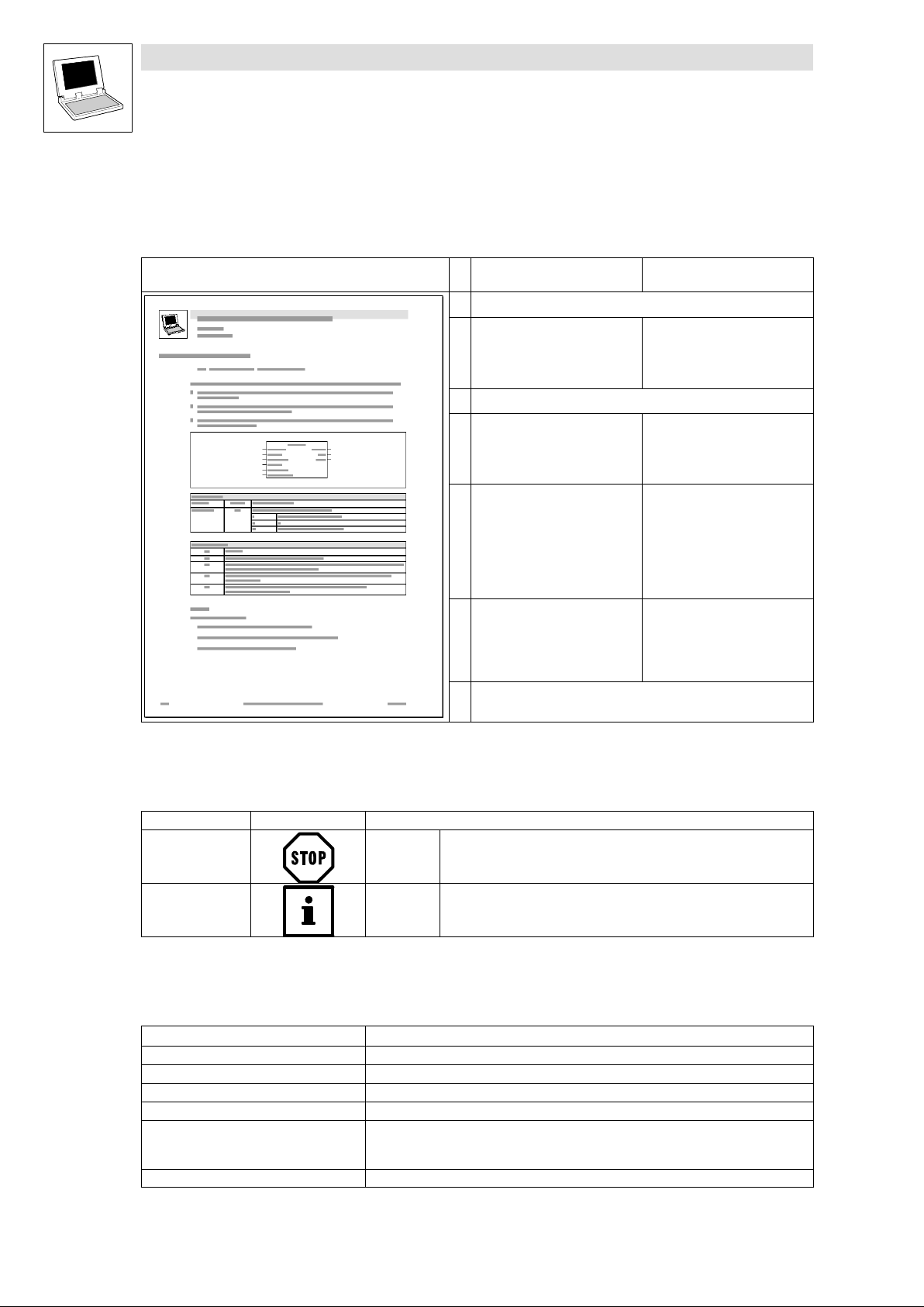
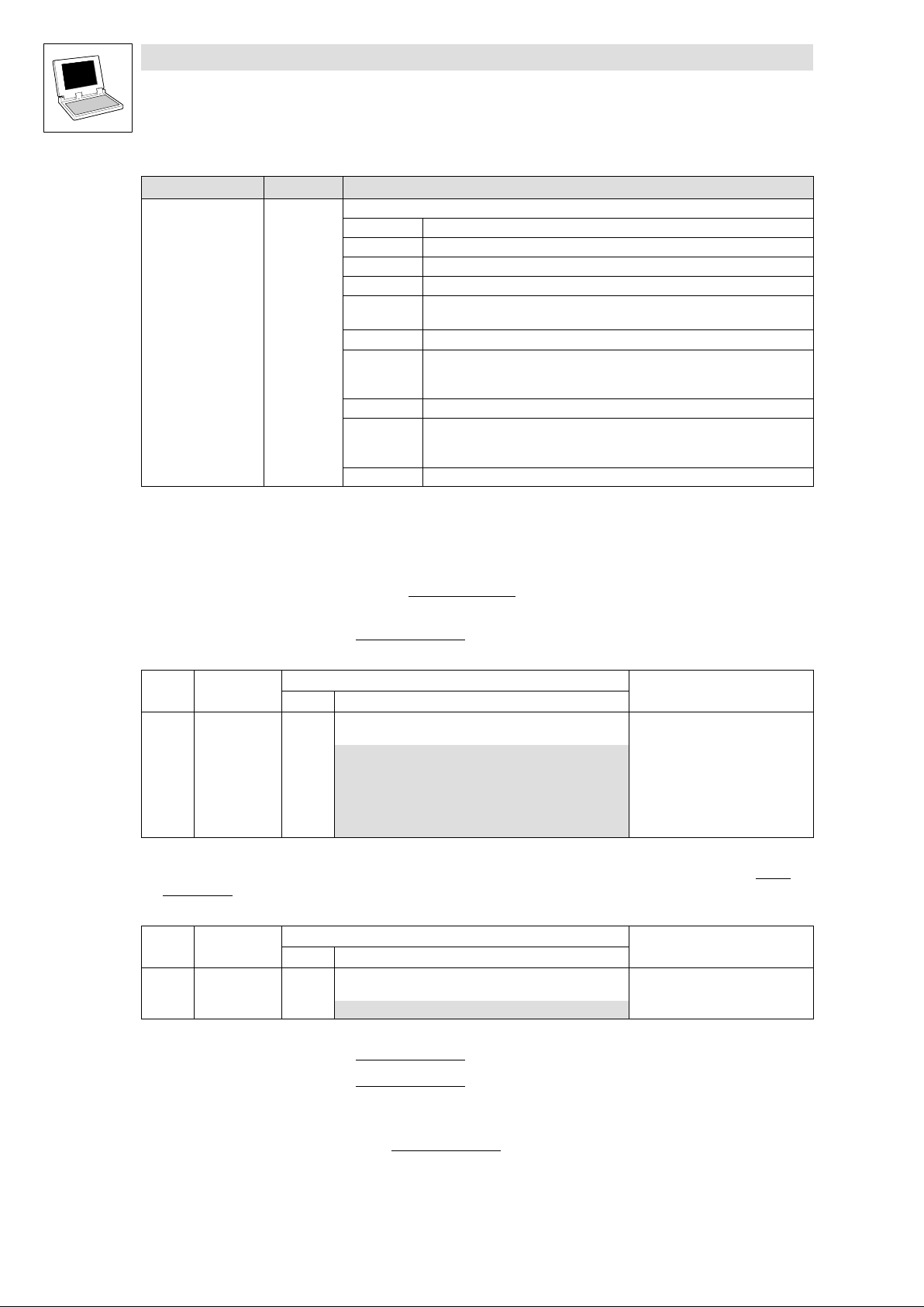
1.1.2 Description layout
All function/function block and system block descriptions contained in this Manual have the same
structure:
Function Function block (FB)/
Heading stating function and function identifier
Declaration of the function:
· Data type of the return value
· Function identifier
· List of transfer parameters
Short description of the most important properties
Function chart including all
associated variables
· Transfer parameters
· Return value
Table giving information about the
transfer parameters:
· Identifiers
· Data type
· Possible settings
· Info
Table giving information about the
return value:
· Data type of the return value
· Possible return values and their
meaning
Additional information
(Notes, tips, application examples, etc.)
system block (SB)
−
FB/SB chart including all
associated variables
· Input variables
· Output variables
Table giving information about the
input and output variables:
· Identifiers
· Data type
· Variable type
· Possible settings
· Info
−
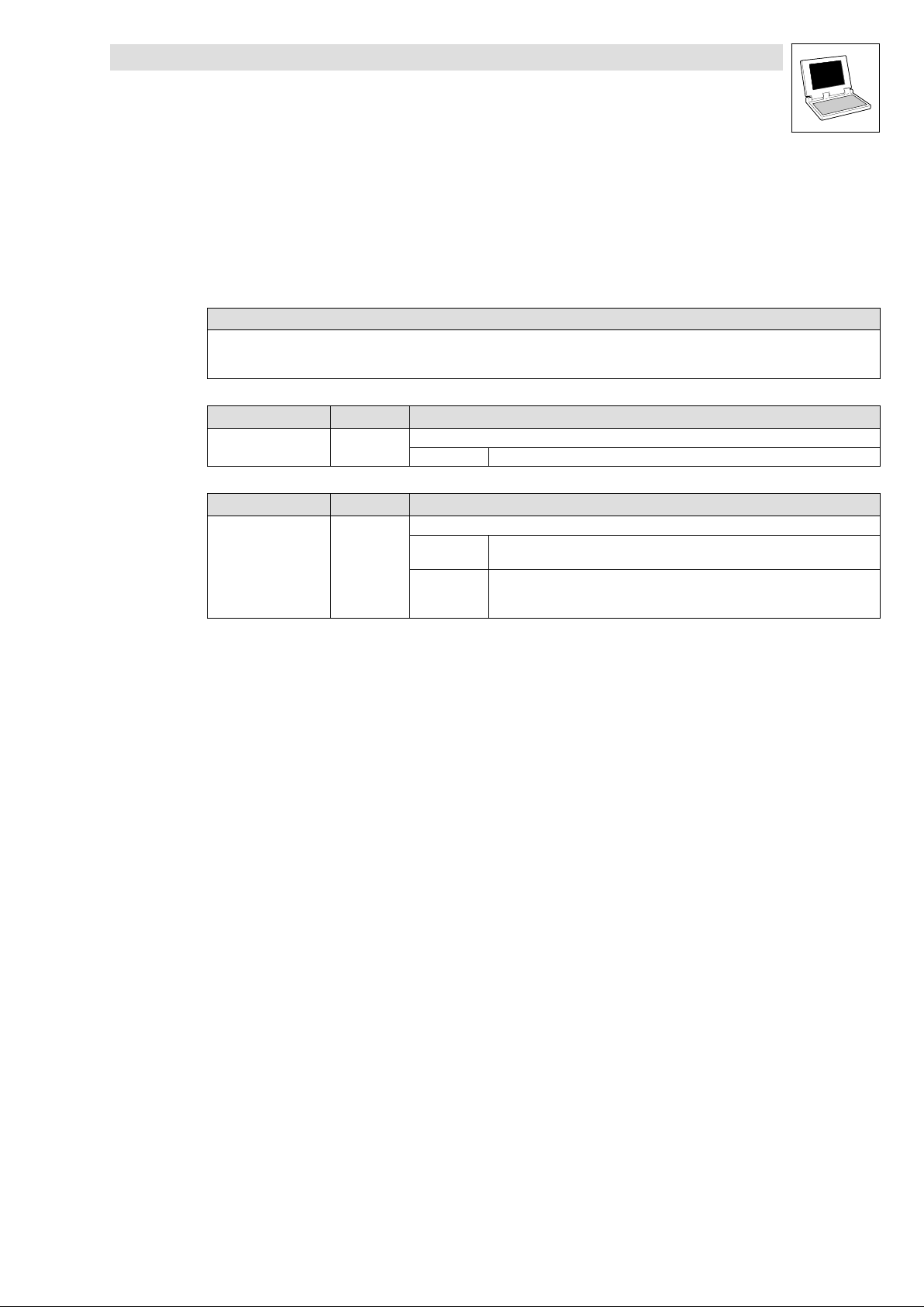
1.1.3 Pictographs used in this Manual
Pictographs used Signal words
Warning of material
damage
Other notes Tip!
Stop! Warns of potential damage to material.
Note!
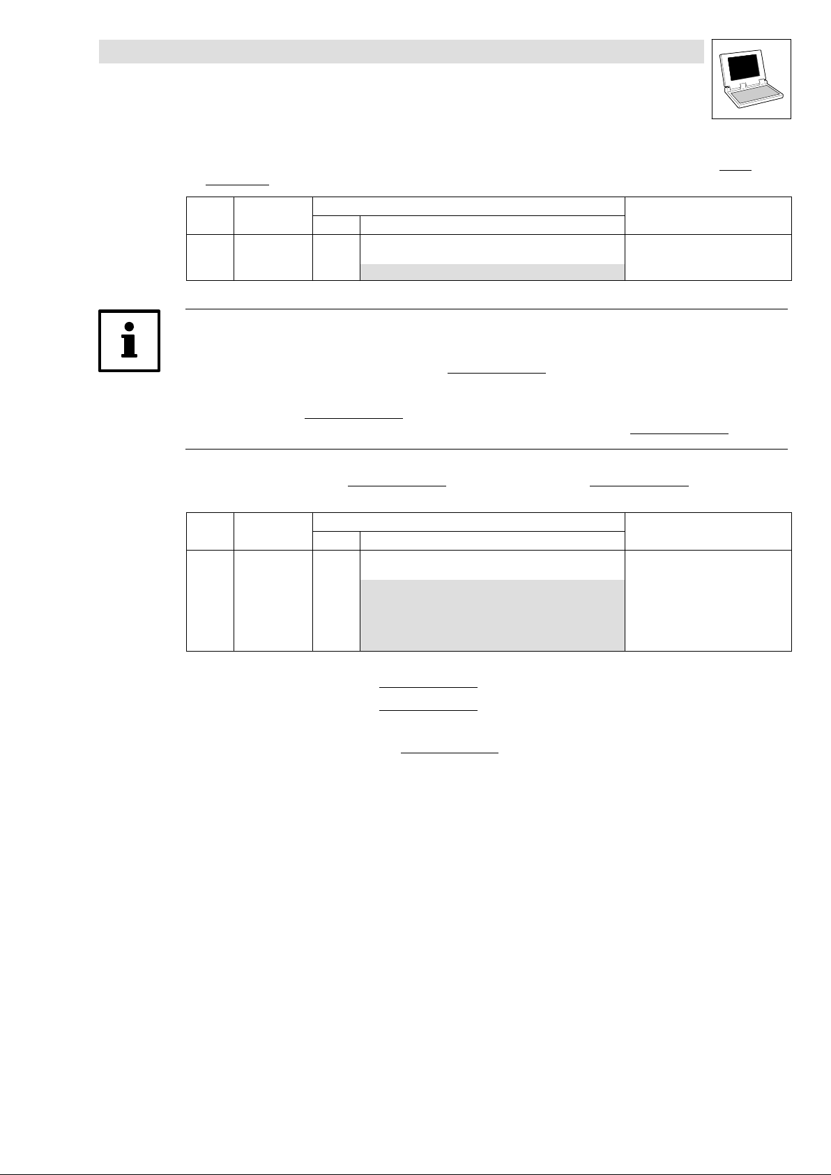
1.1.4 Terminology used
Term In the following text used for
DDS Drive PLC Developer Studio
FB Function block
GDC Global Drive Control (parameterization program from Lenze)
Parameter codes Codes for setting the functionality of a function block
PLC · 9300 Servo PLC
SB System block
· Drive PLC
· Axis module ECSxA "Application"
Possible consequences if disregarded:
Damage to the controller/drive system or its environment
Indicates a tip or note.
.
1−2
LenzeCanDSxDrv.lib EN 1.2
L
Page 7
Function library LenzeCanDSxDrv.lib
Preface and general information
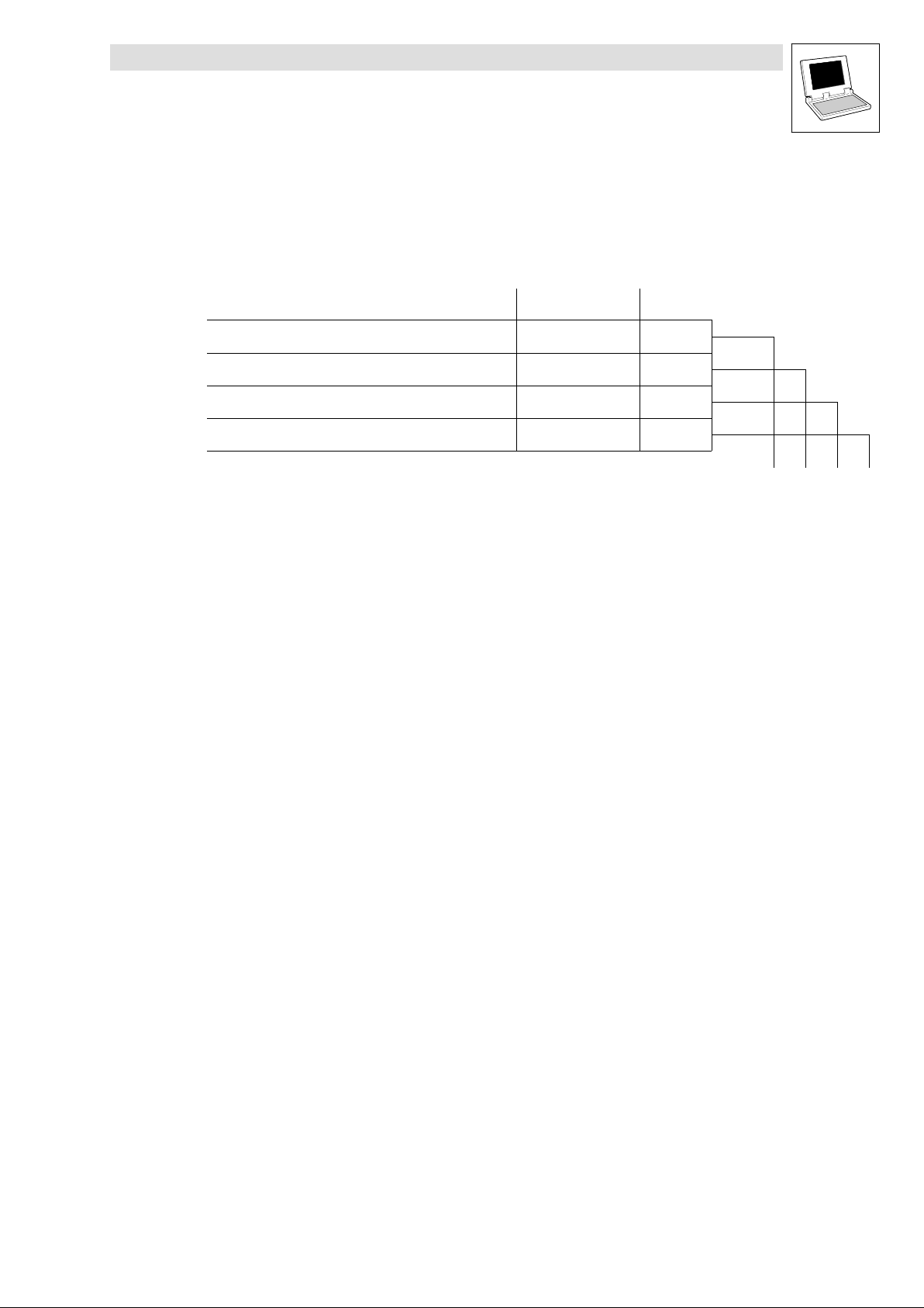
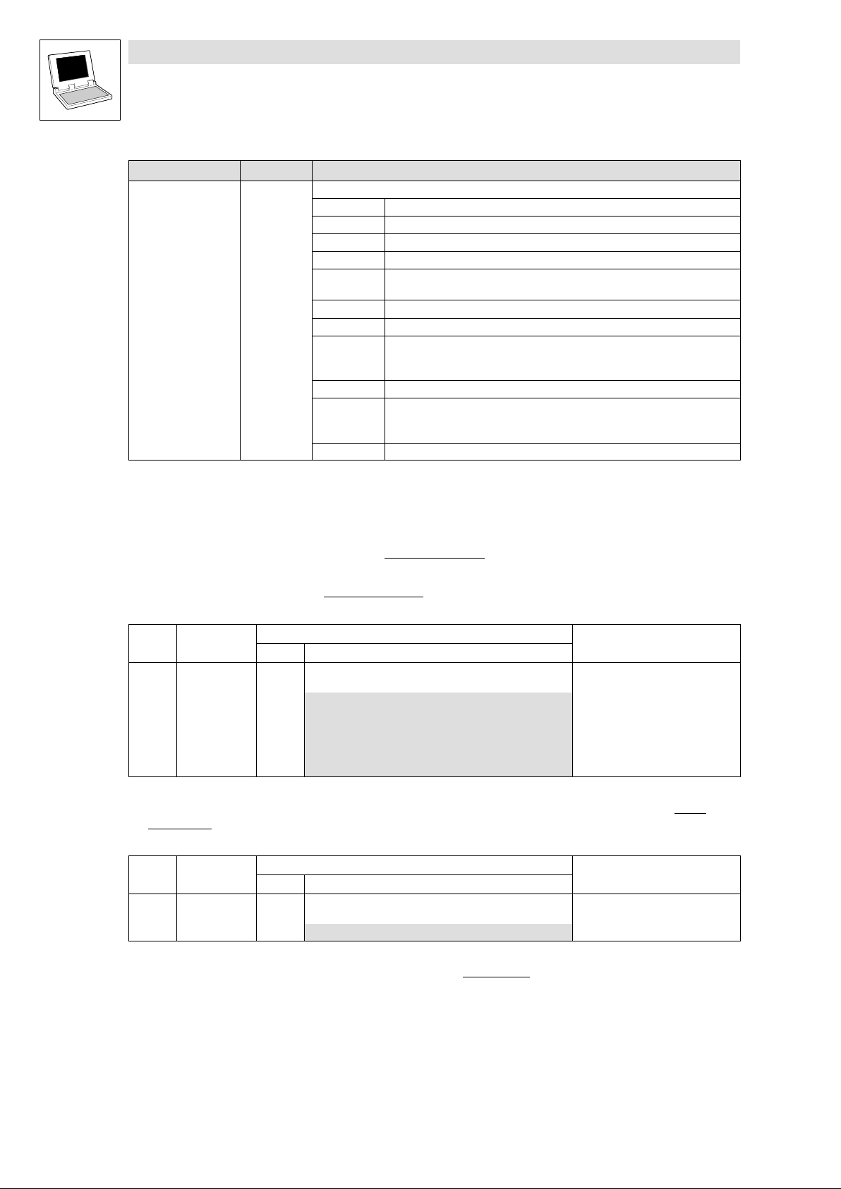
1.2 Version identifiers of the function library
1.2 Version identifiers of the function library
The version of the function library can be found under the global constant
C_w[Function library name]Version .
Version identifiers as of PLC software version 7.x:
Constant Meaning
C_w[FunctionLibraryName]VersionER External Release 01
C_w[FunctionLibraryName]VersionEL External Level 05
C_w[FunctionLibraryName]VersionIR Internal Release 00
C_w[FunctionLibraryName]VersionBN Build No. 00
The value of this constant is a hexadecimal code.
· In the example, "01050000" stands for version "1.05".
Example
value
Version: 01 05 00 00
L
LenzeCanDSxDrv.lib EN 1.2
1−3
Page 8

Function library LenzeCanDSxDrv.lib
Preface and general information
1−4
LenzeCanDSxDrv.lib EN 1.2
L
Page 9
Function library LenzeCanDSxDrv.lib
Introduction
2.1 General information
2 Introduction
2.1 General information
The communication behaviour of the CAN bus devices is defined in a variety of communication
profiles for CAN communication, e. g.:
· DS301 − Standard communication between bus devices
· DS402 − Communication and control of positioning systems
The above communication profiles deal with the following subjects:
· Object directory (connection between index numbers and device functions)
· Network management (start, reset, states of bus devices)
· Bus boot−up messages
· Bus monitoring ("Node Guarding" and "Heartbeat")
· Service data communication (writing/reading of indeces/parameters)
· Process data communication (event−controlled/cyclic data transfer)
· Block data transfer
Tip!
With the functions of function libraries LenzeCanDrv.lib and LenzeCanDSxDrv.lib it is possible to
program communication mechanisms according to the IEC 61131 standard which meet the most
important requirements of the above communication profiles.
2.2 CanDSx driver
The operating system (as of V6.0) of Lenze PLCs includes a specific CanDSx driver which can be
activated by means of the functions of function library LenzeCanDSxDrv.lib.
With the driver it is possible to assign indeces within the PLC to codes other than the automatically
assigned codes.
Note!
· Every Lenze code is assigned to a fixed index using the following formula:
Index = 5FFF
Index = 24575
· The function of the CanDSx driver is limited to the system bus (CAN).
It cannot be used for the second FIF CAN channel of the Drive PLC!
hex
dec
− code
− code
L
LenzeCanDSxDrv.lib EN 1.2
2−1
Page 10

Function library LenzeCanDSxDrv.lib
Introduction
2.2 CanDSx driver
2.2.1 Operating principle − example
Task
A user has implemented a functionality in his PLC which can be parameterised under user code
C3200/5. Code C3200 is automatically assigned to the index
Index = 24575
The communication profile requires, however, that the functionality is parameterised under the index
4101
/subindex 2.
dec
Solution
− code = 24575
dec
− 3200 = 21375
dec
dec
:
dec
Use the functions of function library LenzeCanDSxDrv.lib to redirect index 4101
/subindex 2
dec
within the PLC to code C3200/5 so that the communication profile need not be changed.
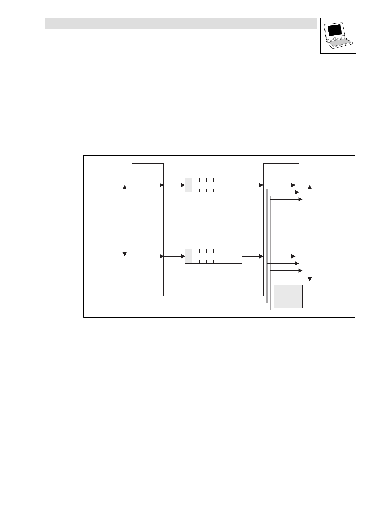
Operating principle
The operating system (as of V6.0) of Lenze PLCs includes a "mapping table" which allows to map
up to 256 codes on codes other than the automatically assigned codes within the PLC.
If a CAN telegram is received and the index is within the valid range, the system checks whether the
index is listed in the mapping table.
· If the index is listed in the mapping table, the PLC accesses the new code assigned to the
index in the mapping table.
If the index is not listed in the mapping table, the PLC accesses the automatically assigned
·
code which results from the above formula.
Index access: 4101/2
SDO telegram
Index number
valid ?
yes
Mapping table
CAN index Lenze code Lenze subcode
4101
4101
20000 0
CAN subindex
1
2 3200 5
3200
3000
Index access: 21475/1
SDO telegram
Index number
valid ?
yes
Mapping table
4
0
CAN index Lenze code Lenze subcode
4101
4101
20000 0
CAN subindex
1
2 3200 5
3200
3000
4
0
Fig. 2−1 Redirection of indeces to codes
2−2
Code access: C3200/5
LenzeCanDSxDrv.lib EN 1.2
Lenze code = 24575 - Index = 24575 - 21475 = 3100
Code access = C3100/1
L
Page 11
Function library LenzeCanDSxDrv.lib
Introduction
2.3 Monitoring mechanisms
2.3 Monitoring mechanisms
The CANopen communication profile (CiA DS301, version 4.01) specifies two optional monitoring
mechanisms to ensure the functionality of the system bus devices: "Heartbeat" and "Node
Guarding".
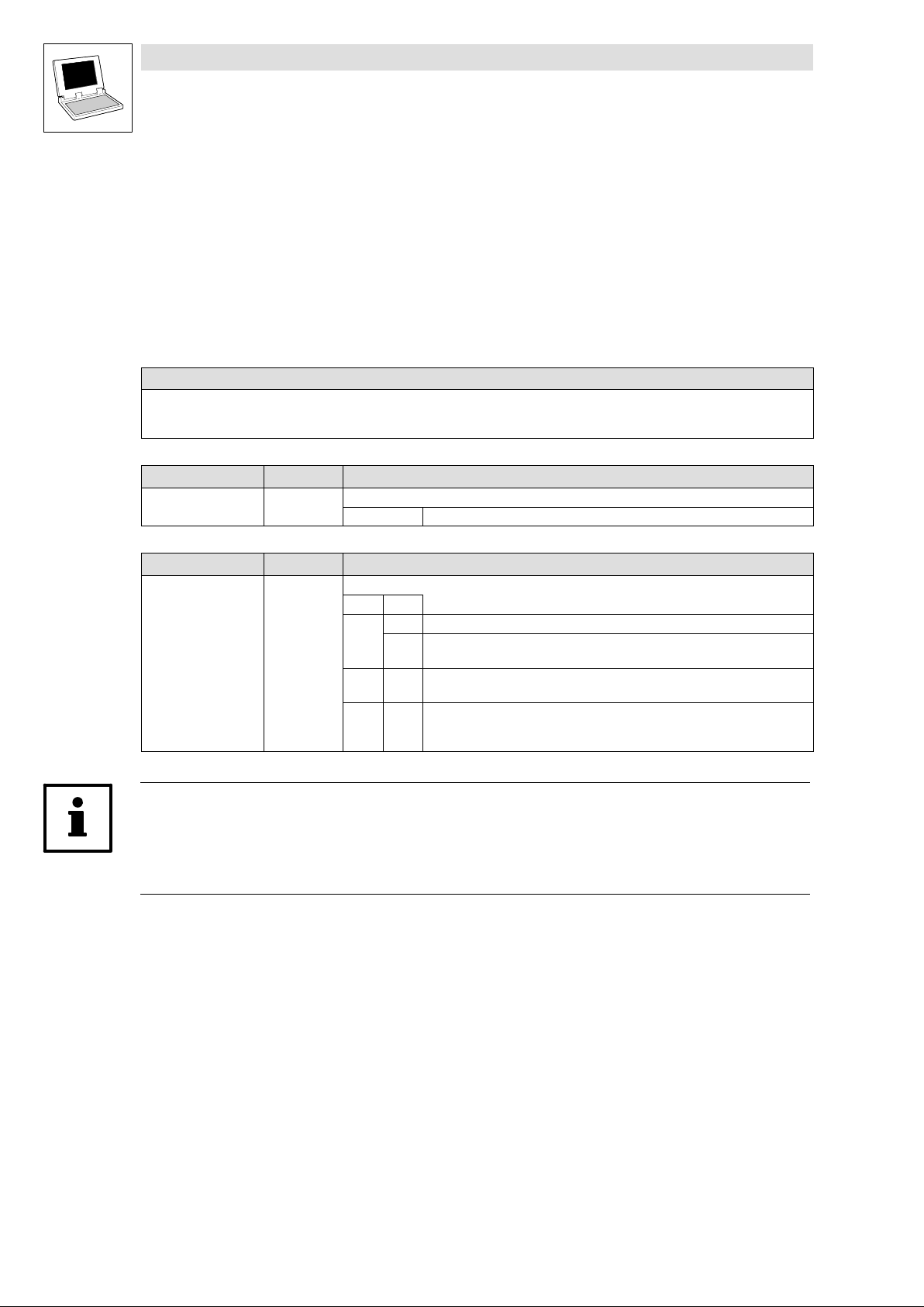
2.3.1 "Heartbeat"
The "Heartbeat" monitoring mechanism is a producer−consumer orientated method. Every bus
device can monitor the state of the other bus devices. A polling message is not required.
Heartbeat Producer Heartbeat Consumer(s)
s
s
Stopped
Operational
Pre-Operational
Boot-Up Event
Heartbeat
Producer
Time
Request
Request
r
r
r:
reserved
s: State of the heartbeat producer:
4
5
127
0
18
Indication(s)
Heartbeat
Consumer
Time
18
Indication(s)
Heartbeat
Event
· A bus device (producer) indicates its communication status by the cyclic transmission of a
"Heartbeat" message.
· The "Heartbeat" message can be received by one, more than one or all bus devices
(consumer) to monitor the corresponding bus device.
· Unless the monitoring bus device (consumer) receives the "Heartbeat" message from the bus
device to be monitored (producer) within the selected monitoring time
(HeartBeatConsumerTime), a "Heartbeat" event will be indicated.
L
LenzeCanDSxDrv.lib EN 1.2
2−3
Page 12

Function library LenzeCanDSxDrv.lib
Introduction
2.3 Monitoring mechanisms
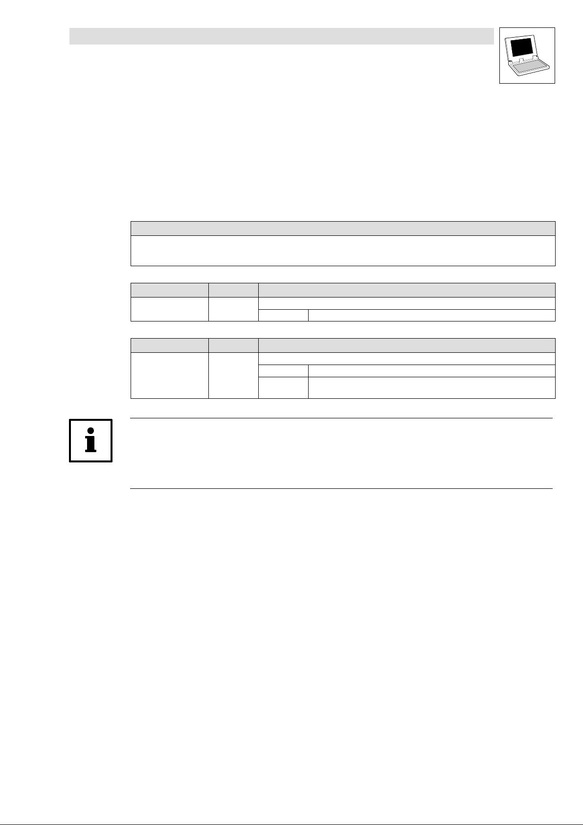
2.3.2 "Node Guarding"
Unlike the "Heartbeat" monitoring mechanism, "Node Guarding" requires a polling message from the
monitoring bus device (NMT master).
NMT Master NMT Slave
RTR
Node
Life
Time
Node
Guard
Time
Request
Confirmation
Request
Confirmation
Node
Guarding
Event
t
RTR
t
t:
Toggle bit
s: NMT Slave state:
Stopped
4
Operational
5
Pre-Operational
127
Boot-Up Event
0
18
s
18
s
Indication
Response
Node
Life
Time
Indication
Response
Life
Guarding
Event
· The monitoring bus device (NMT master) cyclically polls every bus device to be monitored
(NMT slave) using a node−specific remote transmission request telegram.
· As response, the bus device to be monitored (NMT slave) returns its communication status.
· Unless the monitoring bus device (NMT master) receives the message from the bus device to
be monitored (NMT slave) within the selected monitoring time ( NodeLifeTime), a "Node
Guarding" event will be indicated.
· If the status of the monitoring bus device (NMT master) is not polled within its "Node Lifetime",
a "Life Guarding" event will be indicated at the bus device to be monitored (NMT slave).
2−4
LenzeCanDSxDrv.lib EN 1.2
L
Page 13

Function library LenzeCanDSxDrv.lib
Functions/function blocks
3.1 Overview
3 Functions/function blocks
3.1 Overview
Function/FB Info
Index mapping on codes
· The functions only refer to parameter access via the system bus interface of the PLC.
L_CanDSxInitIndexCode Configuration of index mapping ^ 3−2
L_CanDSxOpen Activation of index mapping ^ 3−4
L_CanDSxClose Deactivation of index mapping ^ 3−5
"Hearbeat" monitoring mechanism
L_CanDSxOpenHeartBeat Initialisation of "Heartbeat" ^ 3−6
L_CanDSxHeartBeat Execution of "Heartbeat" ^ 3−7
L_CanDSxCloseHeartBeat Deactivation of "Heartbeat" ^ 3−9
"Node Guarding"monitoring mechanism
L_CanDSxOpenNodeGuarding Initialisation of "Node Guarding" ^ 3−10
L_CanDSxNodeGuarding Execution of "Node Guarding" ^ 3−11
L_CanDSxCloseNodeGuarding Deactivation of "Node Guarding" ^ 3−14
Tip!
For the mapping of codes accessed via the AIF interface, use the functions provided by function
library LenzeAifParMapDrv.lib.
L
LenzeCanDSxDrv.lib EN 1.2
3−1
Page 14

Function library LenzeCanDSxDrv.lib
Functions/function blocks
3.2 L_CanDSxInitIndexCode − Configuration of index mapping
3.2 L_CanDSxInitIndexCode − Configuration of index mapping
Function
This function is used to configure the mapping table and the redirection of indeces to codes other
than the automatically assigned codes.
· With every function call one index and the corresponding Lenze code can be entered in the
mapping table.
Declaration
INT L_CanDSxInitIndexCode (byTabIndex,
wCANIndex, byCANSubIndex,
wLenzeCodeNumber, byLenzeSubCodeNumber);
Transfer parameters Data type Information/possible settings
byTabIndex Byte 0 ... 255 Number of the configuration entry in the mapping table.
Index to be redirected:
wCANIndex Word 1000
byCANSubIndex Byte 0 ... 255 CAN subindex
wLenzeCodeNumber Word 1 ... 7999 Code number
byLenzeSubCode
Number
Byte 0 ... 255 Subcode number
...
hex
8FFF
hex
(4096
dec
36863
dec
Redirection target (Lenze code):
CAN index
...
)
Return value Data type Value/meaning
Integer Status
0 Entry in the mapping table has been successful.
−20 Error: Transfer parameter wCANIndex is invalid.
−30 Error: Transfer parameter wLenzeCodeNumber is invalid.
· A maximum of 256 entries can be entered in the mapping table:
Code to be redirected Redirection target
byTabIndex wCANIndex byCANSubIndex wLenzeCodeNumber byLenzeSubCodeNumber
0
1 4104 2 3200 5
2
...
255
Note!
If the function L_CanDSxInitIndexCode is called while code read or write requests are active an
error may occur!
This is why all actions with code access should be completed before this function is called.
3−2
LenzeCanDSxDrv.lib EN 1.2
L
Page 15

Function library LenzeCanDSxDrv.lib
Functions/function blocks
3.2 L_CanDSxInitIndexCode − Configuration of index mapping
Example
Calling the function in ST:
nReturnInitIndexCode := L_CanDSxInitIndexCode(byTabIndex:=1,
wCANIndex:=4101,
byCANSubIndex:=2,
wLenzeCodeNumber:=3200,
byLenzeSubCodeNumber:=5);
L
LenzeCanDSxDrv.lib EN 1.2
3−3
Page 16
Function library LenzeCanDSxDrv.lib
Functions/function blocks
3.3 L_CanDSxOpen − Initialisation of the CanDSx driver
3.3 L_CanDSxOpen − Initialisation of the CanDSx driver
Function
This function is used to initialise the CanDSx driver in the operating system of the PLC.
· For initialisation, the transfer parameter bOpen must be TRUE.
· After the driver has been initialised, the indeces accessed via the system bus interface will not
be directed to the automatically assigned codes, but redirected to the codes of the mapping
table configured by the function L_CanDSxIndexInitCode.
Declaration
DWORD L_CanDSxOpen (bOpen);
Transfer parameters Data type Information/possible settings
bOpen Bool Initialisation of the CanDSx drive in the operating system.
TRUE The CanDSx driver is initialised in the operating system.
Return value Data type Value/meaning
Double word Status
Bit Value
0 0 Driver initialised.
1 Driver is not initialised.
· Remedy: Call the function with transfer parameter bOpen = TRUE.
1−15 Reserved for future extensions (bits are set to 0).
16−31 Version of function library LenzeCanDSxDrv.lib
· Invalid if bit 0 = 1
· Format: Main version/subversion (e. g. 0103hex = version 1.03)
· Invalid if bit 0 = 1
Note!
If the function L_CanDSxOpen is called while code read or write requests are active an error may
occur!
This is why all actions with code access should be completed before this function is called.
Example
Calling the function in ST:
IF bOpenCanDSxDriver AND NOT bOpen THEN
bOpen := TRUE;
dwReturnOpen := L_CanDSxOpen(bOpen:= TRUE);
END_IF
3−4
LenzeCanDSxDrv.lib EN 1.2
L
Page 17
Function library LenzeCanDSxDrv.lib
Functions/function blocks
3.4 L_CanDSxClose − Deactivation of index mapping
3.4 L_CanDSxClose − Deactivation of index mapping
Function
This function is used to deactivate the mapping table and the redirection of indeces.
· For deactivation, the transfer parameter bClose must be set to TRUE.
· After this function has been executed, the indeces accessed via the system bus interface will
no longer be redirected to the corresponding codes of the mapping table.
Declaration
BOOL L_CanDSxClose (bClose);
Transfer parameters Data type Information/possible settings
bClose Bool Deactivation of index redirections according to the mapping table.
TRUE The CanDSx driver is deactivated in the operating system.
Return value Data type Value/meaning
Bool Status
TRUE The CanDSx driver has been deactivated in the operating system.
FALSE The CanDSx driver has not been deactivated in the operating system.
· Remedy: Call the function with transfer parameter bClose = TRUE.
Note!
If the function L_CanDSxClose is called while code read or write requests are active an error may
occur!
This is why all actions with code access should be completed before this function is called.
Example
Calling the function in ST:
IF bCloseCanDSxDriver AND NOT bClose THEN
bClose := TRUE;
dwReturnClose := L_CanDSxClose(bClose:= TRUE);
END_IF
L
LenzeCanDSxDrv.lib EN 1.2
3−5
Page 18
Function library LenzeCanDSxDrv.lib
Functions/function blocks
3.5 L_CanDSxOpenHeartBeat − Initialisation of "Heartbeat"
3.5 L_CanDSxOpenHeartBeat − Initialisation of "Heartbeat"
Function
The CANopen communication profile (CiA DS301, version 4.01) specifies two optional monitoring
mechanisms to ensure the functionality of the system bus devices: "Heartbeat" and "Node
Guarding".
This function is used to initialise the "Heartbeat" monitoring mechanism of the CanDSx driver.
· For initialisation, the transfer parameter bOpen must be TRUE.
· The actual monitoring is implemented by means of the FB L_CanDSxHeartBeat. (^ 3−7)
· Use the function L_CanDSxCloseHeartBeat to deactivate the "Heartbeat" monitoring
mechanism.
Note!
It is not permitted to use the two monitoring mechanisms simultaneously!
If the transmission cycle time selected for the "Heartbeat" message of the bus device to be
monitored is unequal zero, the "Heartbeat" mechanism will have priority over the "Node Guarding"
mechanism.
(^ 3−9)
Declaration
BOOL L_CanDSxOpenHeartBeat (bOpen);
Transfer parameters Data type Information/possible settings
bOpen Bool Initialisation of "Heartbeat".
TRUE The "Heartbeat" monitoring mechanism of the CanDSx driver is initialised.
Return value Data type Value/meaning
Bool Status
TRUE The "Heartbeat" monitoring mechanism has been initialised.
FALSE A The "Heartbeat" monitoring mechanism has not been initialised.
– Remedy: Call the function with transfer parameter bOpen = TRUE.
or
B The function L_CanDSxOpenNodeGuarding was activated before ("Node
Guarding" is activated).
– Remedy: Call the function L_CanDSxCloseNodeGuarding with transfer
parameter bClose = TRUE (deactivate "Node Guarding").
Example
Calling the function in ST:
bReturnOpenHeartBeat := L_CanDSxOpenHeartBeat(bOpen:= TRUE);
3−6
LenzeCanDSxDrv.lib EN 1.2
L
Page 19

Function library LenzeCanDSxDrv.lib
Functions/function blocks
3.6 L_CanDSxHeartBeat − Execution of "Heartbeat"
3.6 L_CanDSxHeartBeat − Execution of "Heartbeat"
Function block
This FB is used for the cyclic monitoring of the CAN connection between the PLC and other system
bus devices by means of the "Heartbeat" mechanism.
· The FB acts as "Heartbeat consumer". For this, it must be activated in the monitoring PLC.
· Before the function is executed, the "Heartbeat" monitoring mechanism must be initialised in
the CanDSx driver by means of the function L_CanDSxOpenHeartBeat.
L_CanDSxHeartBeat
wDrvNr
byNodeAddr
bRun
tHeartBeatConsumerTime
System bus
CTRL
(CAN)
nState
(^ 3−6)
Heartbeat producer
(Node address = )byNodeAddr
FB call in: o Cyclic task
(PLC_PRG)
Inputs Data type Information/possible settings
wDrv Word Driver number for the CAN interface of the PLC
byNodeAddr Byte Node address of the bus device to be monitored.
bRun Bool Activation of "Heartbeat" monitoring.
þ Time−controlled task
(INTERVAL)
10 On board system bus (CAN)
1 ... 128 Node address
TRUE Monitoring is activated.
o Event−controlled task
· The FB continuously monitors if the bus device with node address byNodeAddr
sends its "Heartbeat" message within the selected monitoring time
tHeartBeatConsumerTime via the system bus and outputs the corresponding
status at nState.
tHeartBeat
ConsumerTime
Time Monitoring time within which the "Heartbeat" message is to be received from the bus device to be
monitored. Otherwise, a "Heartbeat" event ( nState = −10) will be activated.
· Adapt the consumer time to the "Heartbeat producer time" in which the bus device to be
monitored sends the "Hearbeat" message.
· Recommended setting: 200 ... 2000 ms
· Maximum setting: 65535 ms
(EVENT)
o Interrupt task
L
LenzeCanDSxDrv.lib EN 1.2
3−7
Page 20
Function library LenzeCanDSxDrv.lib
Functions/function blocks
3.6 L_CanDSxHeartBeat − Execution of "Heartbeat"
Outputs Data type Information/possible settings
nState Integer Status
300 FB is deactivated ( bRun = FALSE).
127 Bus device to be monitored is in CAN state Pre−operational.
5 Bus device to be monitored is in CAN state Operational.
4 Bus device to be monitored is in CAN state Stopped.
0 Bus device to be monitored is in CAN state Boot−up
or FB is not activated.
−5 Monitoring time tHeartBeatConsumerTime is set to "0".
−10 "Heartbeat" event:
The "Heartbeat" message from the bus device to be monitored was not received
within the selected monitoring timetHeartBeatConsumerTime.
−12 The selected node address ( byNodeAddr) is invalid.
−120 The monitoring mechanism has not been initialised in the CanDSx driver.
· Use the function L_CanDSxOpenHeartBeat to initialise the monitoring
mechanism.
−121 The selected driver number ( wDrvNr) is invalid.
Settings required for the PLC to be monitored
(Valid for 9300 Servo PLC/Drive PLC as from V6.2)
Select the following settings for the PLCto be monitored
to ensure that the PLC will act as "Heartbeat
producer":
1. Set code C0352 of the PLC to be monitored
to "3" to configure the PLC as "slave and
Heartbeat producer":
Code LCD
C0352 CAN mst 0 System bus:
Possible settings
Lenze Selection
0 Slave (boot−up not active)
1 Master (boot−up active)
2 Master with Node Guarding
3 Slave and Heartbeat producer
4 Slave with Node Guarding
Info
Master/slave configuration of the PLC
(SyncReceived no longer possible)
2. Use C0381 to select the time interval for sending the "Heartbeat" message in the PLC to be
monitored. Depending on the bus load, it is recommended to select a setting between 200 ...
2000 ms:
Code LCD
C0381 HeartProTime 0 System bus: Heartbeat (slave):
Possible settings
Lenze Selection
0 {1 msec} 65535
Info
HeartbeatProducerTime
3−8
3. Set code C0003 of the PLC to be monitored to "1" to save the new settings fail−safe.
4. Set code C0358 of the PLC to be monitored
to "1" to carry out a CAN Reset Node.
– As an alternative, the CAN Reset Node can also be carried out by means of a fresh
power−on.
After the CAN Reset Node, the PLC to be monitored
("Hearbeat" producer) will continuously send
the "Heartbeat" telegram within the time interval selected under C0381 via the system bus. The
"Heartbeat" monitoring can now be activated in the monitoring PLC.
LenzeCanDSxDrv.lib EN 1.2
L
Page 21
Function library LenzeCanDSxDrv.lib
Functions/function blocks
3.7 L_CanDSxCloseHeartBeat − Deactivation of "Heartbeat"
3.7 L_CanDSxCloseHeartBeat − Deactivation of "Heartbeat"
Function
This function is used to deactivate the "Heartbeat" monitoring mechanism of the CanDSx driver.
· For deactivation, the transfer parameter bClose must be set to TRUE.
Declaration
BOOL L_CanDSxCloseHeartBeat (bClose);
Transfer parameters Data type Information/possible settings
bClose Bool Deactivation of the "Heartbeat" monitoring mechanism.
TRUE The "Heartbeat" monitoring mechanism of the CanDSx driver is deactivated.
Return value Data type Value/meaning
Bool Status
TRUE The "Heartbeat" monitoring mechanism of the CanDSx driver has been
deactivated.
FALSE The "Heartbeat" monitoring mechanism of the CanDSx driver has not been
deactivated.
· Remedy: Call the function with transfer parameter bClose = TRUE.
Example
Calling the function in ST:
bReturnCloseHeartBeat := L_CanDSxCloseHeartBeat(bClose:= TRUE);
L
LenzeCanDSxDrv.lib EN 1.2
3−9
Page 22

Function library LenzeCanDSxDrv.lib
Functions/function blocks
3.8 L_CanDSxOpenNodeGuarding − Initialisation of "Node Guarding"
3.8 L_CanDSxOpenNodeGuarding − Initialisation of "Node Guarding"
Function
The CANopen communication profile (CiA DS301, version 4.01) specifies two optional monitoring
mechanisms to ensure the functionality of the system bus devices: "Heartbeat" and "Node
Guarding".
This function is used to initialise the "Node Guarding" monitoring mechanism of the CanDSx driver.
· For initialisation, the transfer parameter bOpen must be TRUE.
· The actual monitoring is implemented by means of the FB L_CanDSxNodeGuarding. (^ 3−11)
· Use the function L_CanDSxCloseNodeGuarding to deactivate the "Node Guarding"
monitoring mechanism.
Note!
It is not permitted to use the two monitoring mechanisms simultaneously!
If the transmission cycle time selected for the "Heartbeat" message of the bus device to be
monitored is unequal zero, the "Heartbeat" mechanism will have priority over the "Node Guarding"
mechanism.
(^ 3−14)
Declaration
BOOL L_CanDSxOpenNodeGuarding (bOpen);
Transfer parameters Data type Information/possible settings
bOpen Bool Initialisation of the "Node Guarding" monitoring mechanism.
TRUE The "Node Guarding" monitoring mechanism of the CanDSx driver is initialised.
Return value Data type Value/meaning
Bool Status
TRUE The "Node Guarding" monitoring mechanism has been initialised.
FALSE A The "Node Guarding" monitoring mechanism has not been initialised.
– Remedy: Call the function with transfer parameter bOpen = TRUE.
or
B The PLC has not been configured as "master with Node Guarding".
– Remedy: Set code C0352 to "2" to configure the PLC as "master with Node
Guarding".
Example
Calling the function in ST:
bReturnOpenNodeGuarding := L_CanDSxOpenNodeGuarding(bOpen:= TRUE);
3−10
LenzeCanDSxDrv.lib EN 1.2
L
Page 23

Function library LenzeCanDSxDrv.lib
Functions/function blocks
3.9 L_CanDSxNodeGuarding − Execution of "Node Guarding"
3.9 L_CanDSxNodeGuarding − Execution of "Node Guarding"
Function block
This FB is used for the cyclic monitoring of the CAN connection between the PLC and other system
bus devices by means of the "Node Guarding" mechanism.
· Before the function is executed, the "Node Guarding" monitoring mechanism must be
initialised in the CanDSx driver by means of the function L_CanDSxOpenNodeGuarding.
(^ 3−10)
L_CanDSxNodeGuarding
wDrvNr
byNodeAddr
bRun
tNodeGuardTime
byNodeLifeTimeFactor
System bus
(CAN)
CTRL
1.
2.
nState
(Node address = )byNodeAddr
FB call in: o Cyclic task
(PLC_PRG)
Inputs Data type Information/possible settings
wDrv Word Drive number for the CAN interface of the PLC
byNodeAddr Byte Node address of the bus device to be monitored.
bRun Bool Activation of "Node Guarding".
Þ Time−controlled task
(INTERVAL)
10 On board system bus (CAN)
1 ... 128 Node address
TRUE Monitoring is activated.
NMT Slave
o Event−controlled task
(EVENT)
· The FB uses the transmission cycle selected under tNodeGuardTime, sends a
remote transmission request telegram to the bus device with the node address
byNodeAddr and expects a corresponding response. If the response is not
received within the monitoring time ("NodeLifeTime"), the FB will output the
corresponding status at nState.
tNodeGuardTime Time Transmission cycle of the remote transmission request telegram.
· Time interval in which the PLC sends a status enquiry to the bus device to be monitored (cyclic
polling).
· The setting must correspond to the "GuardTime" (C0382) selected in the PLC to be monitored.
byNodeLifeTimeFactor Byte Factor for the "NodeLifeTime".
"NodeLifeTime" = byNodeLifeTimeFactor tNodeGuardTime
· Unless the bus device to be monitored responds to the status enquiry within the
"NodeLifeTime", a "Node Guarding" event will be activated (nState = −10).
· The setting must correspond to the "NodeLifeTimeFactor" (C0383) selected in the PLC to be
monitored.
o Interrupt task
L
LenzeCanDSxDrv.lib EN 1.2
3−11
Page 24
Function library LenzeCanDSxDrv.lib
Functions/function blocks
3.9 L_CanDSxNodeGuarding − Execution of "Node Guarding"
Outputs Data type Information/possible settings
nState Integer Status
300 FB is deactivated (bRun= FALSE).
127 Bus device to be monitored is in CAN state Pre−operational.
5 Bus device to be monitored is in CAN state Operational.
4 Bus device to be monitored is in CAN state Stopped.
0 Bus device to be monitored is in CAN state Boot−up
or FB is not activated.
−5 Monitoring time tNodeGuardTime or factor byNodeLifeTimeFactor is set to "0".
−9 Response received from bus device to be monitored is invalid.
−10 "Node Guarding" event:
No status response received from bus device to be monitored within the
"NodeLifeTime".
−12 The selected node address (byNodeAddr) is invalid.
−120 The monitoring mechanism has not been initialised in the CanDSx driver.
· Use the function L_CanDSxOpenNodeGuarding to initialise the monitoring
mechanism.
−121 The selected driver number (wDrvNr) is invalid.
Settings required for the PLC to be monitored
(Valid for 9300 Servo PLC/Drive PLC as from V6.2 and ECSxA as from V7.0)
Select the following settings for the PLC to be monitored
to ensure that the PLC will act as "Node
Guarding slave":
1. Set code C0352 of the PLC to be monitored
to "4" to configure the PLC as "slave with Node
Guarding":
Code LCD
C0352 CAN mst 0 System bus:
Possible settings
Lenze Selection
0 Slave (boot−up not active)
1 Master (boot−up active)
2 Master with Node Guarding
3 Slave and Heartbeat producer
4 Slave with Node Guarding
Info
Master/slave configuration of the PLC
(SyncReceived no longer possible)
2. Use C0382 to select the time interval for the status enquiry of the master in the PLC to be
monitored. The value must correspond to the setting at the FB input tNodeGuardTime in the
PLC to be monitored:
Code LCD
C0382 GuardTime 0 System bus: Node Guarding (slave):
Possible settings
Lenze Selection
0 {1 msec} 65535
Info
NodeGuardTime
3−12
3. Set the Node Guarding master C0352/0 = 2 in the monitoring PLC.
LenzeCanDSxDrv.lib EN 1.2
L
Page 25
Function library LenzeCanDSxDrv.lib
Functions/function blocks
3.9 L_CanDSxNodeGuarding − Execution of "Node Guarding"
4. Use C0383 to select the factor for the monitoring time ("NodeLifeTime") in the PLC to be
monitored. The value must correspond to the setting at the FB input byNodeLifeTimeFactor:
Code LCD
C0383 LifeTimeFact. 0 System bus: Node Guarding (slave):
Possible settings
Lenze Selection
0 {1} 255
Info
NodeLifeTimeFactor
Tip!
The "NodeLifeTime" results from the settings for the "NodeGuardTime" (C0382) and the
"NodeLifeTimeFactor" (C0383) in the PLC to be monitored:
NodeLifeTime = NodeGuardTime(C0382)
· Unless the PLC to be monitored receives a status enquiry from the monitoring PLC within the
"NodeLifeTime", a "Life Guarding" event will be activated in the PLC to be monitored
5. Use C0384 of the PLC to be monitored to select how the PLC to be monitored shall respond
to a "Life Guarding" event:
Code LCD
C0384 Err NodeGuard 3 System bus: Node Guarding (slave):
Possible settings
Lenze Selection
0 TRIP
1 Message
2 Warning
3 Off
4 Fail QSP
NodeLifeTimeFactor (C0383)
.
Info
Response to a "Life Guarding" event.
6. Set code C0003 of the PLC to be monitored to "1" to save the new settings fail−safe.
7. Set code C0358 of the PLC to be monitored
to "1" to carry out a CAN reset node.
– As an alternative, the CAN reset node can also be carried out by means of a fresh power−on.
After the CAN reset node, the PLC to be monitored
has been configured as "Node Guarding slave"
and the monitoring can be activated in the "Node Guarding master".
L
LenzeCanDSxDrv.lib EN 1.2
3−13
Page 26

Function library LenzeCanDSxDrv.lib
Functions/function blocks
3.10 L_CanDSxCloseNodeGuarding − Deactivation of "Node Guarding"
3.10 L_CanDSxCloseNodeGuarding − Deactivation of "Node
Guarding"
Function
This function is used to deactivate the "Node Guarding" monitoring mechanism of the CanDSx driver.
· For deactivation, the transfer parameter bClose must be set to TRUE.
Declaration
BOOL L_CanDSxCloseNodeGuarding (bClose);
Transfer parameters Data type Information/possible settings
bClose Bool Deactivation of the "Node Guarding" monitoring mechanism.
TRUE The "Node Guarding" monitoring mechanism of the CanDSx driver is deactivated.
Return value Data type Value/meaning
Bool Status
TRUE The "Node Guarding" monitoring mechanism of the CanDSx driver has been
deactivated.
FALSE The "Node Guarding" monitoring mechanism of the CanDSx driver has not been
deactivated.
· Remedy: Call the function with transfer parameter bClose = TRUE.
Example
Calling the function in ST:
bReturnCloseNodeGuarding := L_CanDSxCloseNodeGuarding(bClose:=
TRUE);
3−14
LenzeCanDSxDrv.lib EN 1.2
L
 Loading...