

Page 1
L
Manual
Global Drive
PLC Developer Studio
Global Drive
Function library
LenzeTpDrv.lib
Page 2

The function library LenzeTpDrv.lib can be used for the following Lenze PLCs:
Type from hardware version from software version
9300 Servo PLC EVS93XX−xT 2K 6.2
Drive PLC EPL10200 1A 6.2
ECSxA ECSxAxxx 1C 7.0
Important note:
The software is supplied to the user as described in this document. Any risks resulting from its quality or use remain the responsibility
of the user. The user must provide all safety measures protecting against possible maloperation.
We do not take any liability for direct or indirect damage, e.g. profit loss, order loss or any loss regarding business.
ã 2002 Lenze Drive Systems GmbH
No part of this documentation may be copied or made available to third parties without the explicit written approval of Lenze Drive
Systems GmbH.
All information given in this documentation has been carefully selected and tested for compliance with the hardware and software
described. Nevertheless, discrepancies cannot be ruled out. We do not accept any responsibility or liability for any damage that may
occur. Required corrections will be included in updates of this documentation.
All product names mentioned in this documentation are trademarks of the corresponding owners.
Version
1.2 10/2006
Page 3

Function library LenzeTpDrv.lib
Contents
1 Preface and general information 1−1 . . . . . . . . . . . . . . . . . . . . . . . . . . . . . . . . . . . . . . . . . . .
1.1 About this Manual 1−1 . . . . . . . . . . . . . . . . . . . . . . . . . . . . . . . . . . . . . . . . . . . . . . . . . . . . . . . . . . . . . . . . .
1.1.1 Conventions used in this Manual 1−1 . . . . . . . . . . . . . . . . . . . . . . . . . . . . . . . . . . . . . . . . . . . . . . .
1.1.2 Description layout 1−2 . . . . . . . . . . . . . . . . . . . . . . . . . . . . . . . . . . . . . . . . . . . . . . . . . . . . . . . . . .
1.1.3 Pictographs used in this Manual 1−2 . . . . . . . . . . . . . . . . . . . . . . . . . . . . . . . . . . . . . . . . . . . . . . .
1.1.4 Terminology used 1−2 . . . . . . . . . . . . . . . . . . . . . . . . . . . . . . . . . . . . . . . . . . . . . . . . . . . . . . . . . .
1.2 Version identifiers of the function library 1−3 . . . . . . . . . . . . . . . . . . . . . . . . . . . . . . . . . . . . . . . . . . . . . . . . .
2 Introduction − touch probe interface 2−1 . . . . . . . . . . . . . . . . . . . . . . . . . . . . . . . . . . . . . . . .
2.1 Touch probe process 2−1 . . . . . . . . . . . . . . . . . . . . . . . . . . . . . . . . . . . . . . . . . . . . . . . . . . . . . . . . . . . . . . .
2.2 Permanently set touch probe inputs 2−2 . . . . . . . . . . . . . . . . . . . . . . . . . . . . . . . . . . . . . . . . . . . . . . . . . . . .
2.3 Selecting digital inputs as touch probe inputs 2−2 . . . . . . . . . . . . . . . . . . . . . . . . . . . . . . . . . . . . . . . . . . . . .
3 Functions/function blocks 3−1 . . . . . . . . . . . . . . . . . . . . . . . . . . . . . . . . . . . . . . . . . . . . . . . .
3.1 L_TpConfigDigInX − Touch probe input configuration 3−1 . . . . . . . . . . . . . . . . . . . . . . . . . . . . . . . . . . . . . . . .
3.2 L_TpGetLastScanDigIn1...4 − Touch probe signal provision 3−2 . . . . . . . . . . . . . . . . . . . . . . . . . . . . . . . . . . . .
l
LenzeTpDrv.lib EN 1.2
i
Page 4

Function library LenzeTpDrv.lib
Contents
ii
LenzeTpDrv.lib EN 1.2
l
Page 5
Function library LenzeTpDrv.lib
Preface and general information
1.1 About this Manual
1 Preface and general information
1.1 About this Manual
This Manual contains information about the function library LenzeTpDrv.lib for the Drive PLC
Developer Studio.
· The function library LenzeTpDrv.lib includes functions and function blocks for configuring the
touch probe interface and accessing touch probe signals from IEC61131−3 applications.
1.1.1 Conventions used in this Manual
This Manual uses the following conventions to distinguish between different types of information:
Variable names
are written in italics in the explanation:
· "The signal at nIn_a ..."
Lenze functions/function blocks
can be recognized by their names. They always begin with an "L_":
· "The FB L_ARIT can ..."
Program listings
are written in "Courier", keywords are printed in bold:
· "IF (ReturnValue < 0) THEN..."
Instances
For function blocks that have one or more first instances there are tables that describe the
corresponding codes:
Variable name L_ARIT1 L_ARIT2 Setting range Lenze
byFunction C0338 C0600 0 ... 5 1
You can access these codes online with Global Drive Control (GDC) or keypad.
Tip!
You can use the Parameter Manager to assign the same codes to these instances that are assigned
in the 9300 servo inverter (V2.0).
l
LenzeTpDrv.lib EN 1.2
1−1
Page 6
Function library LenzeTpDrv.lib
Preface and general information
1.1 About this Manual
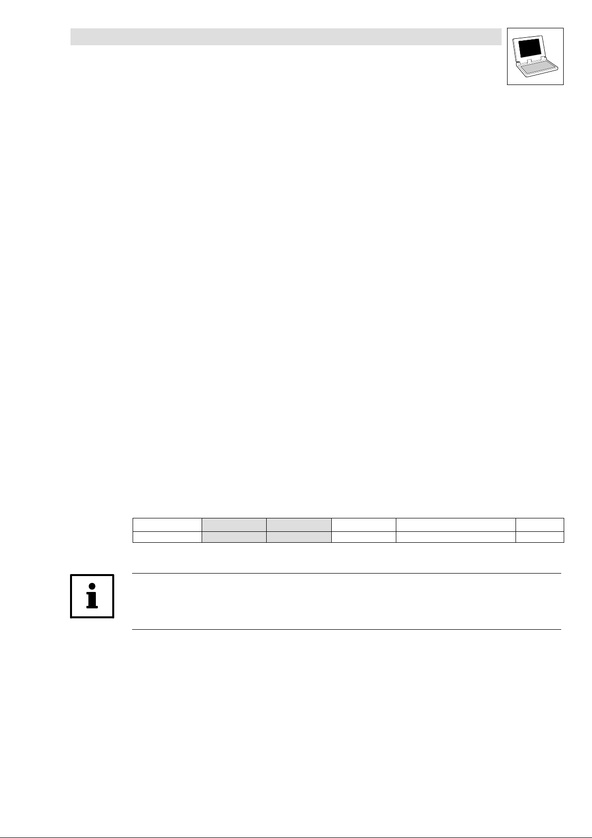
1.1.2 Description layout
All function/function block and system block descriptions contained in this Manual have the same
structure:
Function Function block (FB)/
Heading stating function and function identifier
Declaration of the function:
· Data type of the return value
· Function identifier
· List of transfer parameters
Short description of the most important properties
Function chart including all
associated variables
· Transfer parameters
· Return value
Table giving information about the
transfer parameters:
· Identifiers
· Data type
· Possible settings
· Info
Table giving information about the
return value:
· Data type of the return value
· Possible return values and their
meaning
Additional information
(Notes, tips, application examples, etc.)
system block (SB)
−
FB/SB chart including all
associated variables
· Input variables
· Output variables
Table giving information about the
input and output variables:
· Identifiers
· Data type
· Variable type
· Possible settings
· Info
−
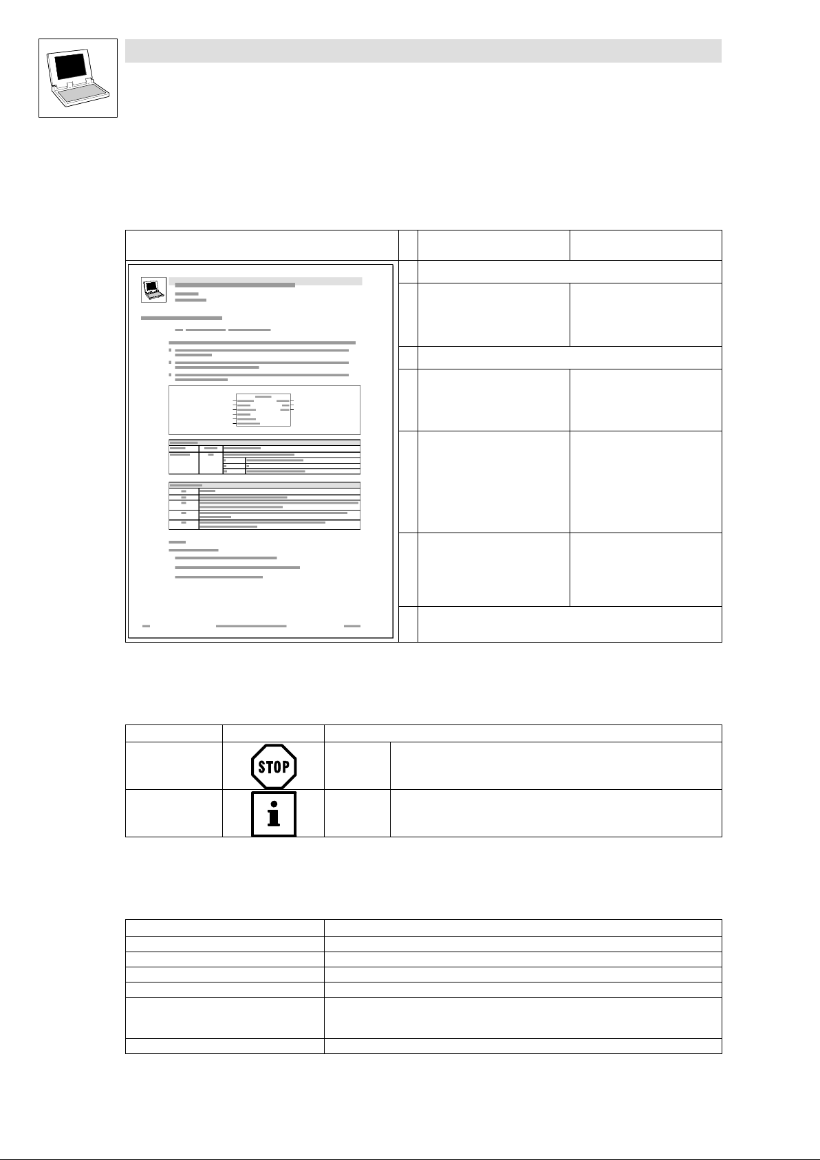
1.1.3 Pictographs used in this Manual
Pictographs used Signal words
Warning of material
damage
Other notes Tip!
Stop! Warns of potential damage to material.
Note!
1.1.4 Terminology used
Term In the following text used for
DDS Drive PLC Developer Studio
FB Function block
GDC Global Drive Control (parameterization program from Lenze)
Parameter codes Codes for setting the functionality of a function block
PLC · 9300 Servo PLC
SB System block
· Drive PLC
· ECSxA "Application" axis module
Possible consequences if disregarded:
Damage to the controller/drive system or its environment
Indicates a tip or note.
.
1−2
LenzeTpDrv.lib EN 1.2
l
Page 7

Function library LenzeTpDrv.lib
Preface and general information
1.2 Version identifiers of the function library
1.2 Version identifiers of the function library
The version of the function library can be found under the global constant
C_w[Function library name]Version .
Version identifiers as of PLC software version 7.x:
Constant Meaning
C_w[FunctionLibraryName]VersionER External Release 01
C_w[FunctionLibraryName]VersionEL External Level 05
C_w[FunctionLibraryName]VersionIR Internal Release 00
C_w[FunctionLibraryName]VersionBN Build No. 00
The value of this constant is a hexadecimal code.
· In the example, "01050000" stands for version "1.05".
Example
value
Version: 01 05 00 00
l
LenzeTpDrv.lib EN 1.2
1−3
Page 8

Function library LenzeTpDrv.lib
Preface and general information
1.2 Version identifiers of the function library
1−4
LenzeTpDrv.lib EN 1.2
l
Page 9

Function library LenzeTpDrv.lib
Introduction
2.1 Touch probe process
2 Introduction − touch probe interface
The functions & function blocks of the function library LenzeTpDrv.lib can be used to configure the
touch probe interface from the POUs. After having been conditioned by the PLC operating system,
they send the touch probe signals to the PLC program.
The function library LenzeTpDrv.lib replaces the previous touch probe interface configuration
concept through Lenze codes. It can be used for Lenze PLCs with operating system V6.2 and higher.
Main features of the function library are:
· Touch probe source selection using the SLOT technology of the DDS control configuration.
· Parameter setting of signal sensitivity and dead time compensation from the POUs using the
function L_TpConfigDigInX.
· Touch probe signal provision in the PLC program through the FBs
L_TpGetLastScanDigIn1...4.
2.1 Touch probe process
The current angle value is stored by a quick interrupt in the operating system when a signal change
occurs at the touch probe activating input:
TP
j
Fig. 2−1 Function chart of a TP; here with MCTRL as source for the angle correction value
Time−equidistant start of an interval−task
j Phase−angle signal
DFIN_dnIncLastScan_p
L
LenzeTpDrv.lib EN 1.2
2−1
Page 10

Function library LenzeTpDrv.lib
Introduction
2.2 Permanently set touch probe inputs
2.2 Permanently set touch probe inputs
The following inputs have been set as permanent touch probe inputs for the 9300 Servo PLC,
Drive PLC and ECSxA:
Digital input Source of the angle correction value
9300 Servo PLC
Drive PLC DIGIN_bIn1_b (I1) DFIN_IO_DigitalFrequency
ECSxA
The above inputs are configured via the corresponding codes of the operating system. Detailed
information can be found in the individual PLC Manuals.
DIGIN_bIn4_b (X5/E4) MCTRL_MotorControl
· Actual motor speed via resolver (X7) or encoder (X8)
DIGIN_bIn5_b (X5/E5) DFIN_IO_DigitalFrequency
· Digital frequency input (X9)
· Encoder input (X3) extension board 3
DIGIN_bIn1 (X6/DI1) DFIN_IO_DigitalFrequency
· Digital frequency input (X8)
DIGIN_bIn2 (X6/DI2) MCTRL_MotorControl
· Actual motor speed via resolver (X7) or encoder (X8)
2.3 Selecting digital inputs as touch probe inputs
In the DDS control configuration you can select which digital inputs are to receive touch probe
functionality.
Proceed as follows to define a digital input as a touch probe input:
1. Open the PLC Configuration in the register card Resources in the Object Organizer.
2. If the SB DIGITAL_IO has not yet been added to the PLC configuration select Insert WAdd
subelementWDIGITAL_IO to add the SB to the PLC configuration.
3. Select the input ( Inputs_DIGIN1...4) to be used as touch probe input.
4. Select Options WReplace elementWInputs_DIGINx_TP to define the selected input as touch
probe input.
– The command Replace element is also available in the context menu:
2−2
LenzeTpDrv.lib EN 1.2
L
Page 11

Function library LenzeTpDrv.lib
Introduction
2.3 Selecting digital inputs as touch probe inputs
5. Go to the register Module parameters and select the source of the angle correction value for
the selected input if the PLC supports more than one source.
– With the 9300 Servo PLC you can, for instance, choose between motor control (MCTRL) and
digital frequency input (DFIN):
The digital input has now been defined as touch probe input. It has the following default settings:
· Signal sensitivity: Rising signal
· Dead time compensation: 0 [inc]
The functions & function blocks described in the following chapter are used for further configuration
possibilities and touch probe signal provision in the PLC program.
Note!
When using a digital input as touch probe input please note:
· If a digital input is used as a touch probe input it cannot be used to start a task.
· Every touch probe input is assigned to an interrupt task. This reduces the number of interrupt
tasks available for the application.
L
LenzeTpDrv.lib EN 1.2
2−3
Page 12

Function library LenzeTpDrv.lib
Introduction
2.3 Selecting digital inputs as touch probe inputs
2−4
LenzeTpDrv.lib EN 1.2
L
Page 13

Function library LenzeTpDrv.lib
Functions/function blocks
3.1 L_TpConfigDigInX − Touch probe input configuration
3 Functions/function blocks
3.1 L_TpConfigDigInX − Touch probe input configuration
Function
With this function you can configure the signal sensitivity and dead time compensation of the touch
probe inputs from a POU.
· This makes, for instance, length measurements easy.
Declaration
INT L_TpConfigDigInX (byDigInSel, byEdgeDetection, dnTpDelay_p);
Transfer parameters Data type Info/possible settings
byDigInSel Byte Touch probe input 9300 Servo PLC Drive PLC ECSxA
1 DIGIN1 ü − −
2 DIGIN2 ü ü −
3 DIGIN3 ü ü ü
4 DIGIN4 − ü ü
byEdgeDetection Byte Signal sensitivity
0 Rising signal
1 Falling signal
2 Rising & falling signal
3 TP detection off
dnTpDelay_p Double integer Dead time compensation of the touch probe sensor
· Value in [inc] referred to the touch probe source.
· Positive values lead to dead time compensation, negative values to a delay of the touch probe
signal.
Note: dnTpDelay serves to compensate a dead time of the touch probe source used. The indication
in increments required here (normally a date would be indicated) can be calculated by multiplying
the dead time given by the manufacturer of the TP sensor by the current speed. This value (in
increments) must be written cyclically via the L_TPConfigDiginX function. The longer the time
distance between the calls of this function, the higher is the inaccuracy in the TP position detection
since changes in speed between the calls are not considered.
L
Return value Data type Value/meaning
Double integer Status
−20 The input selected under byDigInSel has not been configured as a touch probe
−30 The input selected under byDigInSel does not support this functionality or
−40 byEdgeDetection is not within the valid range.
LenzeTpDrv.lib EN 1.2
0 OK, no error.
input in the DDS control configuration.
byDigInSel is impermissible, e. g. in case of 0 or 5.6 .
3−1
Page 14

Function library LenzeTpDrv.lib
Functions/function blocks
3.2 L_TpGetLastScanDigIn1...4 − Touch probe signal provision
3.2 L_TpGetLastScanDigIn1...4 − Touch probe signal provision
Function block
After having been conditioned by the PLC operating system, the PLC program gets the touch probe
signals for the digital inputs from the FBs L_TpGetLastScanDigIn1 ... L_TpGetLastScanDigIn1.
· Signal sensitivity and dead time compensation of the touch probe inputs can be configured
from the POUs using the functionL_TpConfigDigInX.
L_TpGetLastScanDigIn1
nState
Touch probe
CTRL
L_TpGetLastScanDigIn3
Touch probe
CTRL
dnTpLastScan
bTpReceived
nState
dnTpLastScan
bTpReceived
L_TpGetLastScanDigIn2
nState
Touch probe
CTRL
L_TpGetLastScanDigIn4
Touch probe
CTRL
dnTpLastScan
bTpReceived
nState
dnTpLastScan
bTpReceived
Note!
The digital inputs assigned to the FBs must be configured as touch probe inputs in the DDS control
configuration.
3−2
LenzeTpDrv.lib EN 1.2
L
Page 15

Function library LenzeTpDrv.lib
Functions/function blocks
3.2 L_TpGetLastScanDigIn1...4 − Touch probe signal provision
FB call in: o Cyclic task
(PLC_PRG)
Outputs Data type Value/meaning
nState Integer Status
bTpReceived Bool Status signal "Touch probe detected"
· The signal is only active for one task cycle.
dnTpLastScan Double integer Difference in [inc] between latch time and start time of the task.
þ Time−controlled task
(INTERVAL)
3 The signal sensitivity of the touch probe input is set to "TP detection off".
2 The signal sensitivity of the touch probe input is set to "Rising & falling signal".
1 The signal sensitivity of the touch probe input is set to "Falling signal".
0 the signal sensitivity of the touch probe input is set to "Rising signal".
−10 The FB is integrated in a cyclic or event−controlled task.
−20 · The input has not been configured as touch probe input in the DDS control
configuration.
· The module parameters were not configured correctly.
· No process image was created for MCTRL or DFIN in this POU.
−80 The input does not support this functionality.
TRUE Touch probe has been detected.
o Event−controlled task
(EVENT)
o Interrupt task
L
LenzeTpDrv.lib EN 1.2
3−3
Page 16

Function library LenzeTpDrv.lib
Functions/function blocks
3.2 L_TpGetLastScanDigIn1...4 − Touch probe signal provision
Assignment of digital inputs to FBs with the 9300 Servo PLC, Drive PLC and ECSxA
L_TpGetLastScanDigIn1
nState
9300 Servo PLC
Inputs_DIGIN1_TP
E1
Inputs_DIGIN2_TP
E2
Inputs_DIGIN3_TP
E3
DIGIN_bIn1_b
DIGIN_bIn2_b
DIGIN_bIn3_b
Touch probe
CTRL
L_TpGetLastScanDigIn2
Touch probe
CTRL
L_TpGetLastScanDigIn3
Touch probe
CTRL
dnTpLastScan
bTpReceived
nState
dnTpLastScan
bTpReceived
nState
dnTpLastScan
bTpReceived
L_TpGetLastScanDigIn1
nState
Touch probe
CTRL
dnTpLastScan
bTpReceived
-80
ECSxA
Inputs_DIGIN3_TP
I3
Inputs_DIGIN4_TP
I4
DIGIN_bIn3_b
DIGIN_bIn4_b
L_TpGetLastScanDigIn4
nState
Touch probe
CTRL
dnTpLastScan
bTpReceived
L_TpGetLastScanDigIn1
Touch probe
CTRL
nState
L_TpGetLastScanDigIn2
nState
Touch probe
CTRL
dnTpLastScan
bTpReceived
L_TpGetLastScanDigIn3
nState
Touch probe
CTRL
dnTpLastScan
bTpReceived
L_TpGetLastScanDigIn4
nState
Touch probe
CTRL
dnTpLastScan
bTpReceived
L_TpGetLastScanDigIn2
nState
-80
Drive PLC
Touch probe
CTRL
dnTpLastScan
bTpReceived
Inputs_DIGIN2_TP
I2
I3
DIGIN_bIn2_b
Inputs_DIGIN3_TP
DIGIN_bIn3_b
L_TpGetLastScanDigIn3
nState
Touch probe
CTRL
dnTpLastScan
bTpReceived
Inputs_DIGIN4_TP
-80
-80
I4
DIGIN_bIn4_b
L_TpGetLastScanDigIn4
nState
Touch probe
CTRL
dnTpLastScan
bTpReceived
3−4
Note!
If a digital input does not support this functionality because of the PLC type used the value "−80" will
be indicated at the output nState.
LenzeTpDrv.lib EN 1.2
L
Page 17

Function library LenzeTpDrv.lib
Functions/function blocks
3.2 L_TpGetLastScanDigIn1...4 − Touch probe signal provision
Functional sequence:
1. The touch probe is signal−controlled via the digital input.
2. If a touch probe has occurred bTPReceived will be set to TRUE.
– This status signal is only active for one task cycle.
3. After the start of the task, dnTpLastScan indicates the number of increments [inc/ms] which
have been counted since touch probe activation.
Tip!
If you want to make the touch probe signals available to other function blocks for further processing
you only have to connect the outputs with the corresponding inputs:
L_TpGetLastScanDigIn2
nState
Touch probe
CTRL
dnTpLastScan
bTpReceived
dnActLastScan_p
bActTPReceived
Touch
probe
L_Example
L
LenzeTpDrv.lib EN 1.2
3−5
 Loading...