

Page 1
L
Manual
Global Drive
PLC Developer Studio
Global Drive
Function library
LenzeIOSystem.lib
Page 2

The LenzeIOSystem.lib and LenzeIOSystemVxxxx.lib function libraries can be used for
the following Lenze PLC devices:
Type As of hardware version As of software version
Drive PLC EPL10200_xI VC 2.x
Drive PLC EPL10200_xT VC 2.x
9300 Servo PLC EVS93xx_xI 2K 2.x
9300 Servo PLC EVS93xx_xT 2K 2.x
ECSxA ECSxAxxx 1C 7.0
Important note:
The software is supplied to the user as described in this document. Any risks resulting from its quality or use remain the responsibility
of the user. The user must provide all safety measures protecting against possible maloperation.
We do not take any liability for direct or indirect damage, e.g. profit loss, order loss or any loss regarding business.
ã 2006 Lenze Drive Systems GmbH
No part of this documentation may be copied or made available to third parties without the explicit written approval of Lenze Drive
Systems GmbH.
All information given in this documentation has been carefully selected and tested for compliance with the hardware and software
described. Nevertheless, discrepancies cannot be ruled out. We do not accept any responsibility or liability for any damage that may
occur. Required corrections will be included in updates of this documentation.
All product names mentioned in this documentation are trademarks of the corresponding owners.
Version 1.7 11/2006
Page 3

Function library LenzeIOSystem.lib
Contents
1 Preface and general information 1−1 . . . . . . . . . . . . . . . . . . . . . . . . . . . . . . . . . . . . . . . . . . .
1.1 About this Manual 1−1 . . . . . . . . . . . . . . . . . . . . . . . . . . . . . . . . . . . . . . . . . . . . . . . . . . . . . . . . . . . . . . . . .
1.1.1 Conventions used in this Manual 1−1 . . . . . . . . . . . . . . . . . . . . . . . . . . . . . . . . . . . . . . . . . . . . . . .
1.1.2 Structure of the descriptions 1−2 . . . . . . . . . . . . . . . . . . . . . . . . . . . . . . . . . . . . . . . . . . . . . . . . . .
1.1.3 Pictographs used in this Manual 1−2 . . . . . . . . . . . . . . . . . . . . . . . . . . . . . . . . . . . . . . . . . . . . . . .
1.1.4 Terminology used 1−2 . . . . . . . . . . . . . . . . . . . . . . . . . . . . . . . . . . . . . . . . . . . . . . . . . . . . . . . . . .
1.2 Version identifiers of the function library 1−3 . . . . . . . . . . . . . . . . . . . . . . . . . . . . . . . . . . . . . . . . . . . . . . . . .
2 Introduction 2−1 . . . . . . . . . . . . . . . . . . . . . . . . . . . . . . . . . . . . . . . . . . . . . . . . . . . . . . . . . . .
2.1 Introduction 2−1 . . . . . . . . . . . . . . . . . . . . . . . . . . . . . . . . . . . . . . . . . . . . . . . . . . . . . . . . . . . . . . . . . . . . .
2.2 Design concept 2−1 . . . . . . . . . . . . . . . . . . . . . . . . . . . . . . . . . . . . . . . . . . . . . . . . . . . . . . . . . . . . . . . . . .
2.3 Minimum configuration 2−2 . . . . . . . . . . . . . . . . . . . . . . . . . . . . . . . . . . . . . . . . . . . . . . . . . . . . . . . . . . . . .
3 Application examples 3−1 . . . . . . . . . . . . . . . . . . . . . . . . . . . . . . . . . . . . . . . . . . . . . . . . . . .
3.1 Modular decentralised I/O system 3−1 . . . . . . . . . . . . . . . . . . . . . . . . . . . . . . . . . . . . . . . . . . . . . . . . . . . . .
3.2 Compact decentralised I/O system 3−5 . . . . . . . . . . . . . . . . . . . . . . . . . . . . . . . . . . . . . . . . . . . . . . . . . . . . .
4 Function blocks for parameterisation 4−1 . . . . . . . . . . . . . . . . . . . . . . . . . . . . . . . . . . . . . . .
4.1 L_IOParComGuarding − Monitoring function 4−2 . . . . . . . . . . . . . . . . . . . . . . . . . . . . . . . . . . . . . . . . . . . . . .
4.2 L_IOParAlnModule − Parameterisation function 4−4 . . . . . . . . . . . . . . . . . . . . . . . . . . . . . . . . . . . . . . . . . . . .
4.3 L_IOParAOutModule − Parameterisation function 4−7 . . . . . . . . . . . . . . . . . . . . . . . . . . . . . . . . . . . . . . . . . . .
4.4 L_IOParAlAOModule − Parameterisation function 4−9 . . . . . . . . . . . . . . . . . . . . . . . . . . . . . . . . . . . . . . . . . . .
4.5 L_IOParSSIModule − Parameterisation function 4−12 . . . . . . . . . . . . . . . . . . . . . . . . . . . . . . . . . . . . . . . . . . . .
4.6 L_IOParCounterModule − Counter function 4−14 . . . . . . . . . . . . . . . . . . . . . . . . . . . . . . . . . . . . . . . . . . . . . . .
4.7 L_IOParCounterDIModule − Counter function 4−16 . . . . . . . . . . . . . . . . . . . . . . . . . . . . . . . . . . . . . . . . . . . . . .
4.8 L_IOParPDO15 − Parameterisation function 4−18 . . . . . . . . . . . . . . . . . . . . . . . . . . . . . . . . . . . . . . . . . . . . . .
4.9 L_IOParPDO610 − Parameterisation function 4−22 . . . . . . . . . . . . . . . . . . . . . . . . . . . . . . . . . . . . . . . . . . . . . .
4.10 L_IOParCompactModule − Parameterisation function 4−26 . . . . . . . . . . . . . . . . . . . . . . . . . . . . . . . . . . . . . . . .
5 Function blocks for process data processing 5−1 . . . . . . . . . . . . . . . . . . . . . . . . . . . . . . . . .
5.1 L_IOData15 − Coordinate data 5−2 . . . . . . . . . . . . . . . . . . . . . . . . . . . . . . . . . . . . . . . . . . . . . . . . . . . . . . . .
5.2 L_IOData610 − Coordinate data 5−5 . . . . . . . . . . . . . . . . . . . . . . . . . . . . . . . . . . . . . . . . . . . . . . . . . . . . . . .
5.3 L_IOCompactModule − Coordinate data 5−8 . . . . . . . . . . . . . . . . . . . . . . . . . . . . . . . . . . . . . . . . . . . . . . . . .
5.4 L_IOCounterDataToIO − Counter function 5−11 . . . . . . . . . . . . . . . . . . . . . . . . . . . . . . . . . . . . . . . . . . . . . . . .
5.5 L_IOCounterDataFromIO − Counter function 5−13 . . . . . . . . . . . . . . . . . . . . . . . . . . . . . . . . . . . . . . . . . . . . . .
5.6 L_IOCounterDIModuleDataToIO − Counter function 5−14 . . . . . . . . . . . . . . . . . . . . . . . . . . . . . . . . . . . . . . . . . .
5.7 L_IOCounterDIModuleDataFromIO − Counter function 5−15 . . . . . . . . . . . . . . . . . . . . . . . . . . . . . . . . . . . . . . .
5.8 L_IOSSIDataToIO − Counter function 5−16 . . . . . . . . . . . . . . . . . . . . . . . . . . . . . . . . . . . . . . . . . . . . . . . . . . . .
5.9 L_IOSSIDataFromIO − Counter function 5−17 . . . . . . . . . . . . . . . . . . . . . . . . . . . . . . . . . . . . . . . . . . . . . . . . . .
5.10 L_IOConvByteToByteArray − Conversion function 5−18 . . . . . . . . . . . . . . . . . . . . . . . . . . . . . . . . . . . . . . . . . . .
5.11 L_IOConvByteArrayToByte − Conversion function 5−19 . . . . . . . . . . . . . . . . . . . . . . . . . . . . . . . . . . . . . . . . . . .
5.12 L_IODInModule − Bit conversion 5−20 . . . . . . . . . . . . . . . . . . . . . . . . . . . . . . . . . . . . . . . . . . . . . . . . . . . . . . .
5.13 L_IODOutModule − Bit conversion 5−21 . . . . . . . . . . . . . . . . . . . . . . . . . . . . . . . . . . . . . . . . . . . . . . . . . . . . .
5.14 L_IOAInModule − Signal conversion 5−22 . . . . . . . . . . . . . . . . . . . . . . . . . . . . . . . . . . . . . . . . . . . . . . . . . . . .
5.15 L_IOAOutModule − Signal conversion 5−23 . . . . . . . . . . . . . . . . . . . . . . . . . . . . . . . . . . . . . . . . . . . . . . . . . . .
l
LenzeIOSystem.lib EN 1.7
i
Page 4

Function library LenzeIOSystem.lib
Contents
6 Appendix 6−1 . . . . . . . . . . . . . . . . . . . . . . . . . . . . . . . . . . . . . . . . . . . . . . . . . . . . . . . . . . . . .
6.1 Signal functions for analog inputs EPM−T310 6−1 . . . . . . . . . . . . . . . . . . . . . . . . . . . . . . . . . . . . . . . . . . . . .
6.2 Signal functions for analog outputs EPM−T320 6−4 . . . . . . . . . . . . . . . . . . . . . . . . . . . . . . . . . . . . . . . . . . . .
6.3 Signal functions for analog inputs and outputs EPM−T330 6−6 . . . . . . . . . . . . . . . . . . . . . . . . . . . . . . . . . . . .
6.4 Measured value scaling 6−9 . . . . . . . . . . . . . . . . . . . . . . . . . . . . . . . . . . . . . . . . . . . . . . . . . . . . . . . . . . . .
6.5 Selecting the counter modes EPM−T410 6−10 . . . . . . . . . . . . . . . . . . . . . . . . . . . . . . . . . . . . . . . . . . . . . . . . .
7 Index 7−1 . . . . . . . . . . . . . . . . . . . . . . . . . . . . . . . . . . . . . . . . . . . . . . . . . . . . . . . . . . . . . . . .
ii
LenzeIOSystem.lib EN 1.7
l
Page 5

Function library LenzeIOSystem.lib
Preface and general information
1.1 About this Manual
1 Preface and general information
1.1 About this Manual
This Manual contains information on the LenzeIOSystem.lib and LenzeIOSystemVxxxx function
libraries for the Drive PLC Developer Studio.
1.1.1 Conventions used in this Manual
This Manual uses the following conventions to distinguish between different types of information:
Variable identifiers
are printed in italics in the explanatory text:
· "By means of bReset..."
Tip!
Information about the conventions used for variables of Lenze system blocks, function blocks and
functions can be obtained from the appendix of the DDS online documentation "Introduction into
IEC 61131−3 programming". The conventions ensure universal and uniform labelling and support
the readability of PLC programs.
Lenze functions/function blocks
can be identified by the name. They always begin with an "L_":
· "By means of the L_IOPar..."FB
Program listings
are itemised in the "Courier" font, the keywords being printed bold:
· "IF (ReturnValue < 0) THEN..."
L
LenzeIOSystem.lib EN 1.7
1−1
Page 6
Function library LenzeIOSystem.lib
Preface and general information
1.1 About this Manual
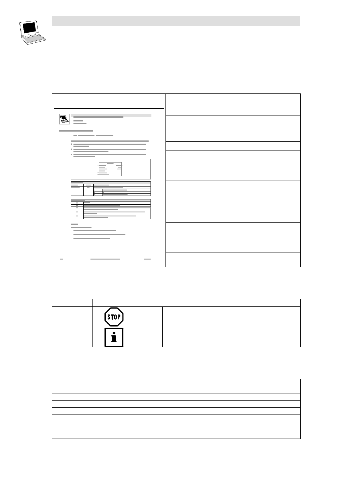
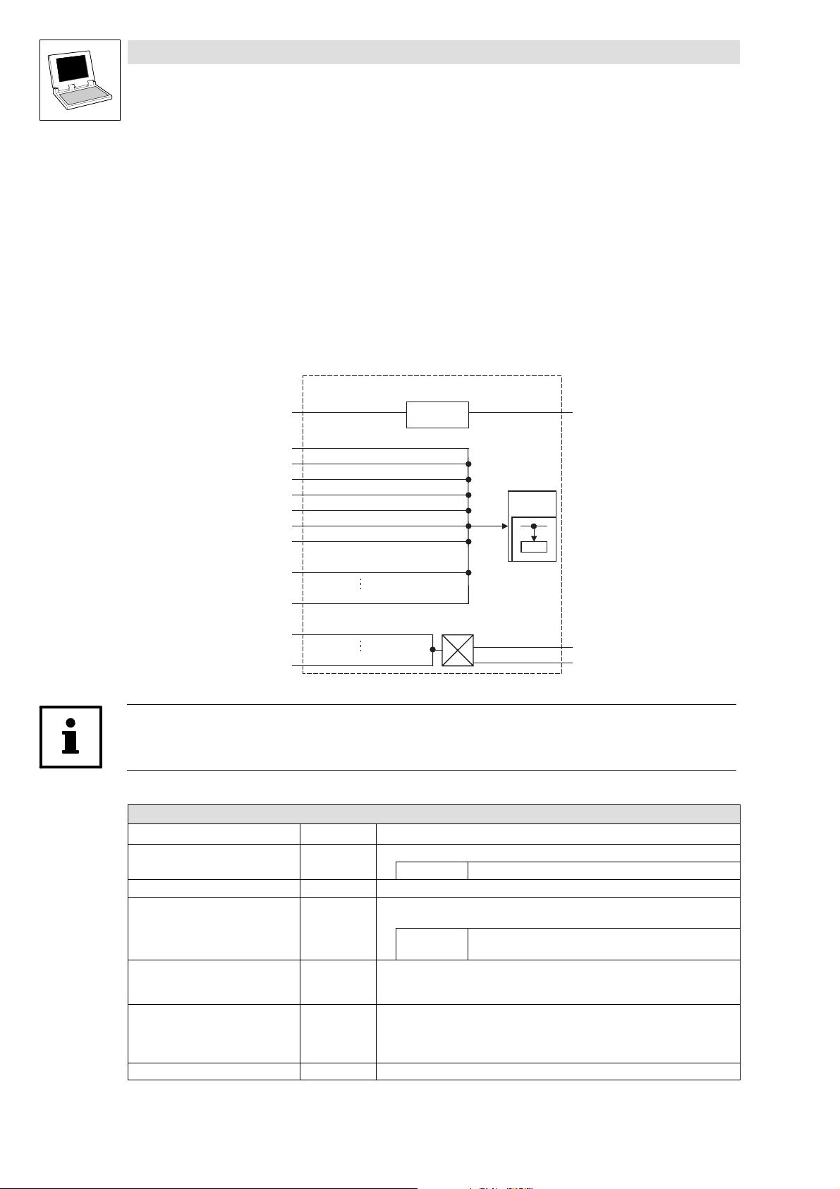
1.1.2 Structure of the descriptions
The descriptions of the individual functions/function blocks as well as system blocks in this Manual
are structured in a standardised manner according to the following pattern:
Function Function block (FB)/
Headline with function and identifier
Declaration of the function:
· Data type of the return value
· Function identifier
· List of the transfer parameters
Short description with the most important features
Graph showing the function
including all corresponding
variables
· Transfer parameters
· Return value
Table giving information on the
transfer parameters:
· Identifiers
· Data type
· Possible settings
· Information
Table giving information on the
return value:
· Data type of the return value
· Possible return values and their
meaning
Further information
(comments, tips, application examples, etc.)
system block (SB)
−
System block/function block chart
including all corresponding
variables
· Input variables
· Output variables
Table giving information about
input and output variables:
· Identifiers
· Data type
· Variable type
· Possible settings
· Information
−
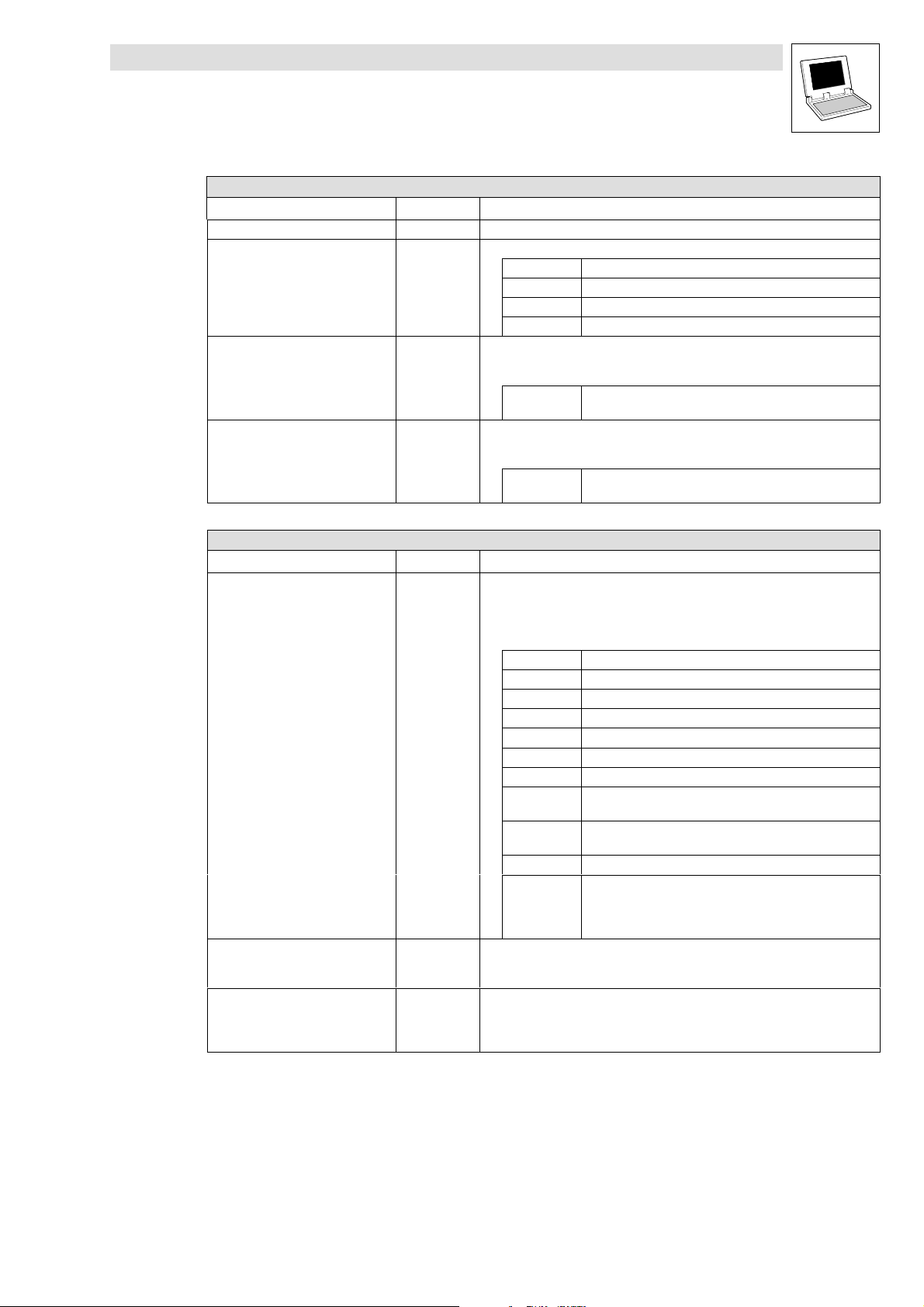
1.1.3 Pictographs used in this Manual
Pictohraphs used Signal words
Warning of
material damage
More notes Tip!
Stop! Warns of potential damage to material.
Note!
1.1.4 Terminology used
Term In this Manual used for
DDS Drive PLC Developer Studio
FB Function block
GDC Global Drive Control (parameter setting program from Lenze)
Parameter codes Codes for setting the function of a function block
PLC · 9300 servo PLC
SB System block
· Drive PLC
· ECSxA "Application" axis module
Possible consequences if disregarded:
Damage of the controller/drive system or its environment.
Indicates a tip or note.
1−2
LenzeIOSystem.lib EN 1.7
L
Page 7
Function library LenzeIOSystem.lib
Preface and general information
1.2 Version identifiers of the function library
1.2 Version identifiers of the function library
The version of the function library can be found under the global constant
C_w[Function library name]Version .
Version identifiers as of PLC software version 7.x:
Constant Meaning
C_w[FunctionLibraryName]VersionER External Release 01
C_w[FunctionLibraryName]VersionEL External Level 05
C_w[FunctionLibraryName]VersionIR Internal Release 00
C_w[FunctionLibraryName]VersionBN Build No. 00
The value of this constant is a hexadecimal code.
· In the example, "01050000" stands for version "1.05".
Example
value
Version: 01 05 00 00
L
LenzeIOSystem.lib EN 1.7
1−3
Page 8

Function library LenzeIOSystem.lib
Preface and general information
1−4
LenzeIOSystem.lib EN 1.7
L
Page 9

Function library LenzeIOSystem.lib
Introduction
2.1 Introduction
2 Introduction
2.1 Introduction
The user is offered suitable function blocks in function libraries to enable decentralised I/O system
support by Lenze PLC products.
These function blocks are integrated in an IEC 61131 program and assist in the parameterisation of
the I/O system as well as in process data processing. Furthermore, they provide digital and analog
I/O system input and output information.
LenzeI/OSystem.lib
This library provides all setting options. User configuration via user codes is not required.
2.2 Design concept
The function libraries contain two types of function blocks.
· Parameter data blocks
· Process data blocks
Parameter data blocks
These function blocks allow the modification of index information in the decentralised I/O system and
the transmission of specified data. These data are transmitted only once to the I/O system during the
initialisation phase.
· Parameterising communication
– These blocks parameterise communication relationships
(Identifier assignment for PDO communication, transmission method, transmission period,
etc.) between PLC and I/O system.
– These settings are mandatory for data exchange.
· Parameterising modules and monitoring functions
– The function blocks are required for
individual parameterisation of analog modules,
individual parameterisation of counter modules,
communication monitoring
Process data blocks
These function blocks provide assistance for evaluating and further processing the current process
data information from the I/O system inputs in the PLC program.
Information and data can be transferred into the process via the output modules.
· Process data blocks to transmit and receive I/O data between PLC and I/O system.
· Process data blocks for I/O signal conversion.
L
LenzeIOSystem.lib EN 1.7
2−1
Page 10
Function library LenzeIOSystem.lib
Introduction
2.3 Minimum configuration
2.3 Minimum configuration
A minimum configuration must be established to integrate the I/O system, consisting of one
parameter data block L_IOParPDO15 to parameterise communication relationships and one
process data block L_IOData15 to evaluate the input/output information.
The information of the parameter block is transmitted to the I/O system and the function block for
PLC I/O system process data exchange.
Data exchange between the output of the parameter block and the input of the process data block
is possible with the help of a global variable.
Note!
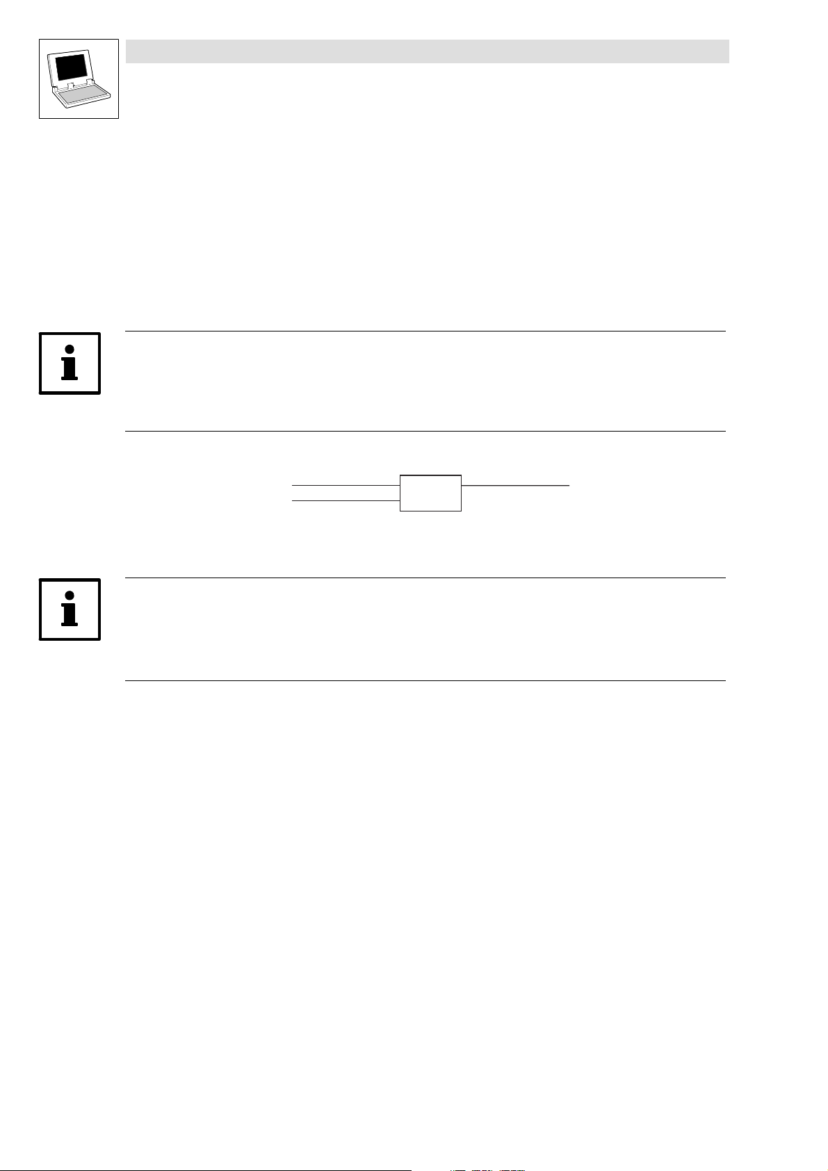
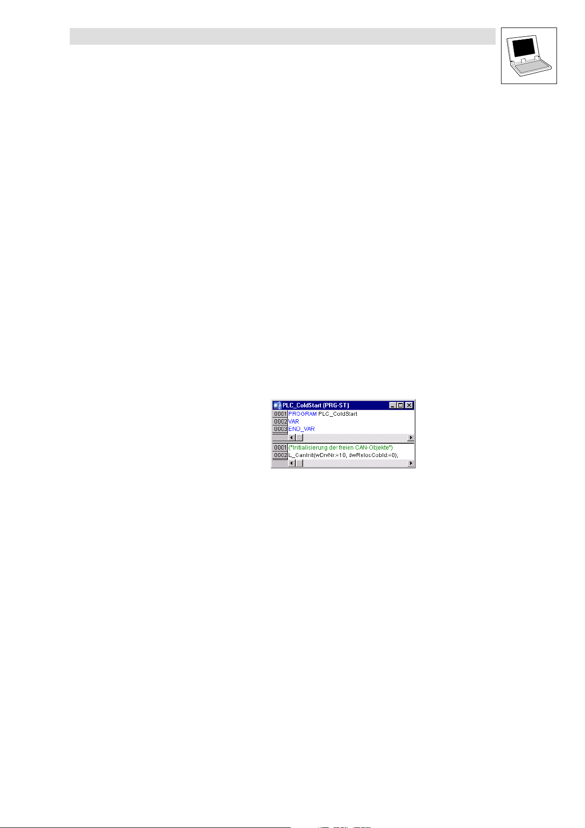
The function libraries for the decentralised I/O system are based on unassigned CAN objects, so that
the CAN driver must be initialised via block L_CANInit.
The block L_CANInit is located in the Lenze library LenzeCanDrv.lib.
wDrvNr
10
dwRelocCobld
0
L_CanInit
L_CanInit
CTRL
10 = System bus
0 = ID range 832..895 (Servo PLC only)
Note!
The identifier range is limited in the case of the 9300 Servo PLC.
Use of function blocks L_IOParPDO15 and L_IOParPDO610 requires adjustment of the
Cob IDs from PDO4 onwards.
2−2
LenzeIOSystem.lib EN 1.7
L
Page 11
Function library LenzeIOSystem.lib
Application examples
3.1 Modular decentralised I/O system
3 Application examples
The examples were generated with DDS version 2.0. Examples concerning the I/O system are given
in the directory C:\Programme\Lenze\DDS_P_2_20\Projects\IOSystem\Samples
3.1 Modular decentralised I/O system
The modular decentralised I/O system with eight digital inputs and outputs is integrated into a PLC
program with the help of LenzeIOSystem.lib.
During this process, the following steps must be carried out in the given order:
1. Initialise the CAN driver
2. Parameterise the communication conditions
3. Program the process data exchange between PLC and I/O system
4. Initialise the codes
Initialising the CAN driver
Communication between the PLC and the I/O system is based on "unassigned CAN objects"
(control, alarm, diagnostics...). These objects are available in DDS from version 2.x onwards.
To initialise the unassigned CAN objects, the function L_CANInit must be requested once only in the
system POU PLC_ColdStart.
Parameterising the communication conditions
Function block L_IOParPDO15 for parameterising the communication conditions of PDO1−PDO5 is
integrated into the SFC editor and necessarily is to be used in every project. This function block
specifies the communication parameters in the I/O system.
The values are transferred to the process data block L_IOData15 as a structure (STRUCT) in order
to match the communication parameters of the devices (controller and I/O system).
On program execution, this step is executed only once at the beginning.
L
LenzeIOSystem.lib EN 1.7
3−1
Page 12
Function library LenzeIOSystem.lib
Application examples
3.1 Modular decentralised I/O system
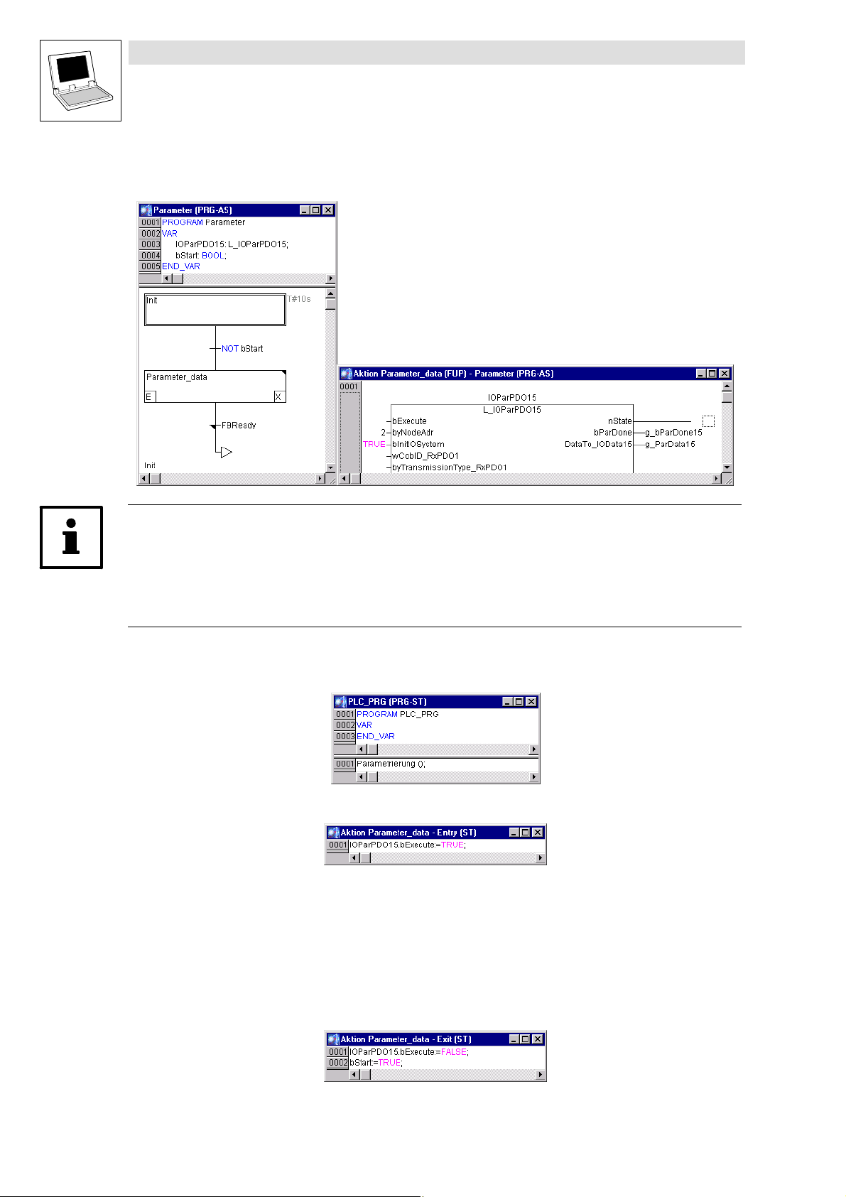
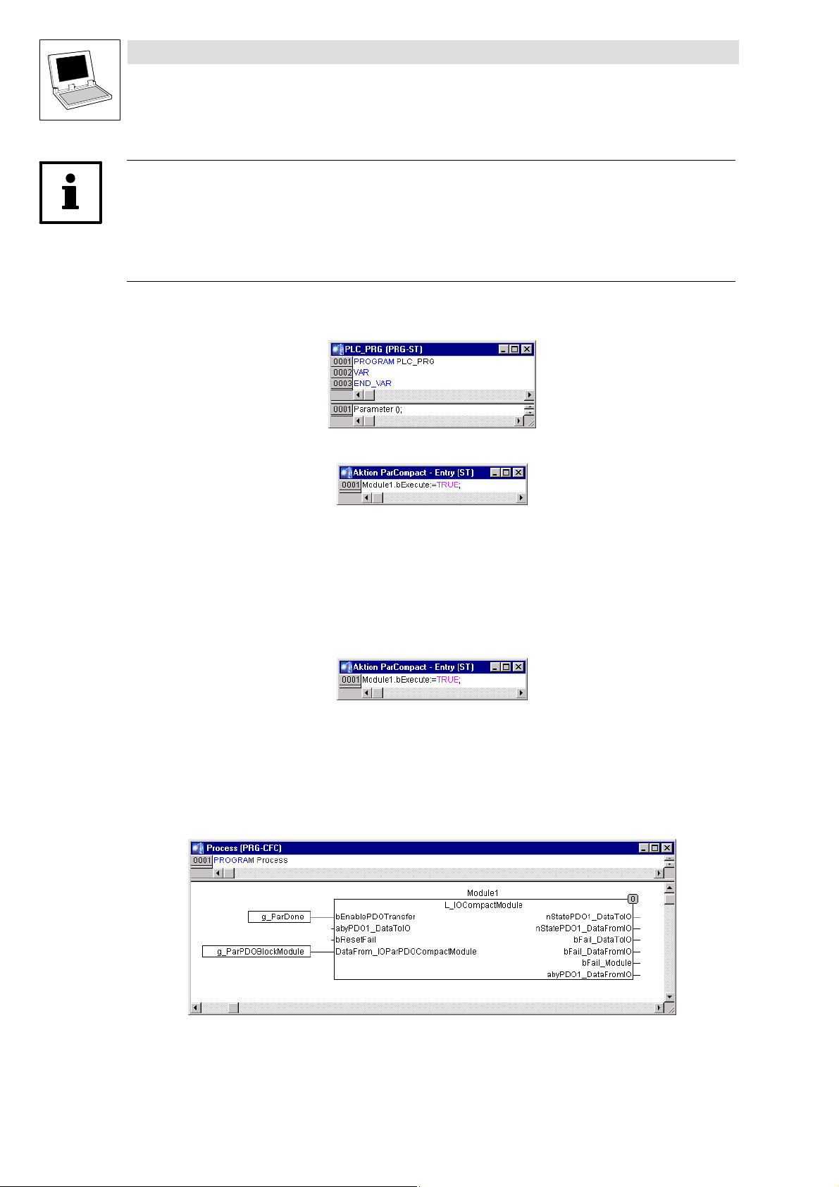
Then the Parameter program that must be generated in the SFC editor follows. With the invocation
of the function block instance, the step Parameter_data has the action generated in the FBD editor.
Note!
· Enter a minimum time of ten seconds for step Init via the menu command ExtrasÞStep
attibutes.... Correct entry: T#10s
Make sure that step Parameter_data is not executed before the initialisation phase of the I/O system
is complete. This is achieved with a minimum time of ten seconds.
As this POU must be processed cyclically, the program is invoked in the PLC_PRG (main program).
The sequential function chart ensures a cyclic task.
The parameterisation process is started via the initial action in step Parameter_data.
Once the parameterisation is complete, the final action in step Parameter_data sets input bExecute
to FALSE and variable bStart to TRUE.
Variable bStart ensures that step Parameter_data is executed
· on switching on
· on reset and subsequent starting.
When the parameterisation is complete, the PLC_PRG (main program) stops in step Init. It does not
impose an extra burden on the target system during subsequent program operation.
3−2
LenzeIOSystem.lib EN 1.7
L
Page 13
Function library LenzeIOSystem.lib
Application examples
3.1 Modular decentralised I/O system
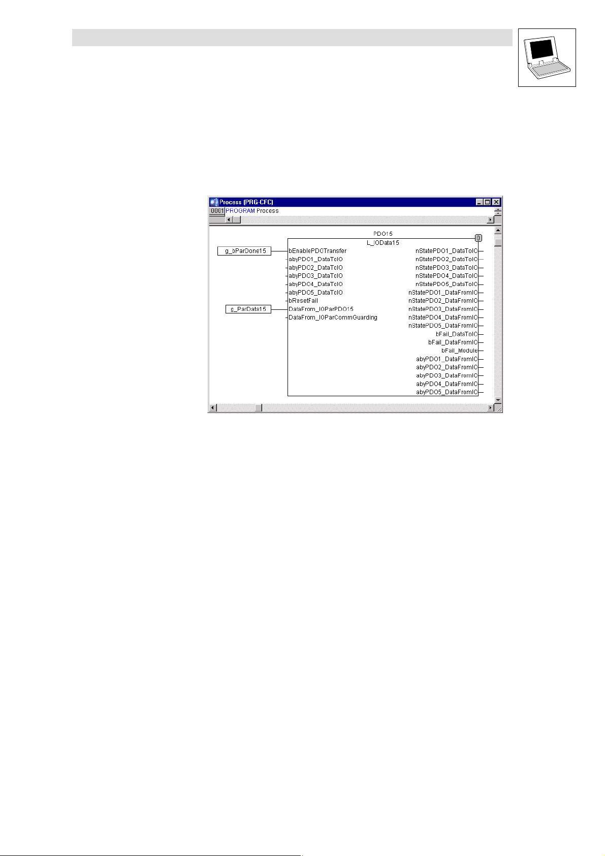
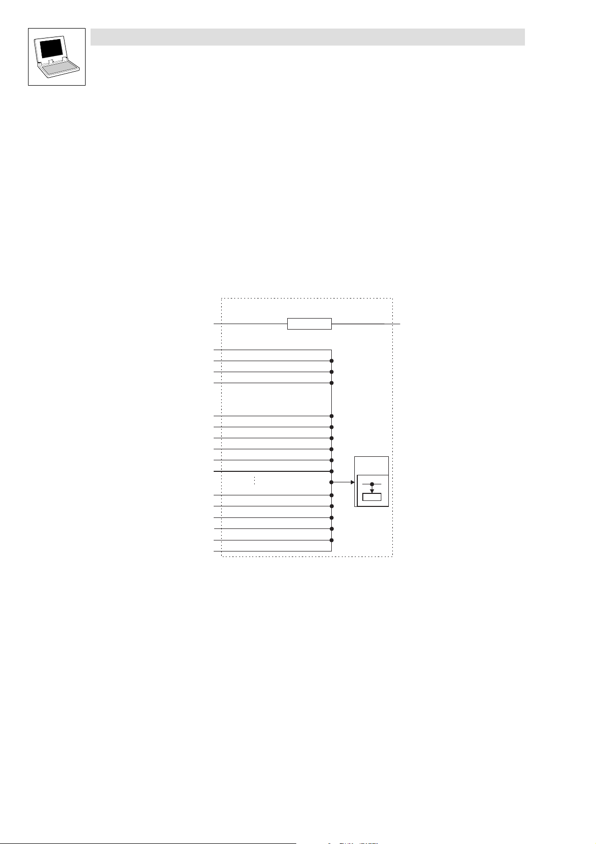
Programming the process data exchange between PLC and I/O system
The CFC editor is used to generate a program named Process.
· Declare an instance of function block L_IOData15 in Process.
· Generate two inputs in the CFC editor, assign names g_bParDone15 and g_ParData15 and
attach these to the corresponding inputs of function block L_IOData15 as shown in the figure.
Several conversion blocks are available to evaluate input data and to transfer output data.
Function block L_IOData15 transmits output data to the I/O system and receives input data from
there.
At input DataFrom_IOParPDO15, CAN communication relationships between PLC and I/O system
are transmitted from parameterisation block L_IOParPDO15 to process data block L_IOData15.
Process data transmission is started after parameterisation via a High signal at input
bEnablePDOTransfer.
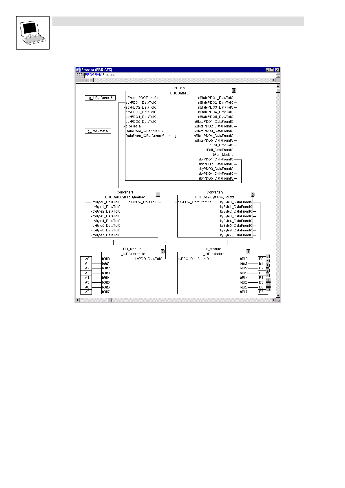
Data conversion for evaluating individual channels
The program Process can be extended as follows:
· Use the menu command ExtrasÞOrder to indicate the sequence.
· Drag the individual function blocks to their positions in order to make the program sequence
comprehensible.
L
LenzeIOSystem.lib EN 1.7
3−3
Page 14
Function library LenzeIOSystem.lib
Application examples
3.1 Modular decentralised I/O system
3−4
Function block L_IOData15 supplies the transmit and receive data as 8 byte information via the CAN
telegram.
The two converters convert the information into individual bytes.
A digital input and output module maps the individual bits.
Initialising the codes
Initialise the following codes in the PLC
· Code C0352
Subcode 0 = 1
Defines PLC as a CAN master so that the configuration enters the Operational state.
· Code C0356
Subcode 1 = 10000
Increases the boot−up time to10s
· Code C2104
Subcode 0 = 1
Starts the PLC program automatically after switching on the mains
LenzeIOSystem.lib EN 1.7
L
Page 15

Function library LenzeIOSystem.lib
Application examples
3.2 Compact decentralised I/O system
3.2 Compact decentralised I/O system
The compact module EPM − T832 with 24 digital inputs and 8 digital outputs is integrated into a PLC
program with the help of LenzeIOSystem.lib.
During this process, the following steps must be carried out in the given order:
1. Initialise the CAN driver
2. Parameterise the communication conditions
3. Program the process data exchange between PLC and I/O system
4. Initialise the codes
Initialising the CAN driver
Communication between the PLC and the I/O system is based on "unassigned CAN objects"
(control, alarm, diagnostics...). These objects are available in DDS from version 2.x onwards.
To initialise the unassigned CAN objects, the function L_CANInit must be requested once only in the
system POU PLC_ColdStart.
Parameterising the communication conditions
Function block L_IOParCompactModule for parameterising the communication conditions is
integrated into the SFC editor and necessarily is to be used in every project. This function block
specifies the communication parameters in the I/O system.
The values are transferred to the process data block L_IOCompactModule as a structure (STRUCT)
in order to match the communication parameters of the devices (controller and I/O system).
On program execution, this step is executed once only at the beginning.
Then the Parameter program that must be generated in the SFC editor follows. With the invocation
of the function block instance, the step ParCompact has the action generated in the FBD editor.
L
LenzeIOSystem.lib EN 1.7
3−5
Page 16
Function library LenzeIOSystem.lib
Application examples
3.2 Compact decentralised I/O system
Note!
· Enter a minimum time of ten seconds for step Init via the menu command ExtrasÞStep
attributes.... Correct entry: T#10s
Make sure that step Parameter_data is not executed before the initialisation phase of the I/O system
is complete. This is achieved with a minimum time of ten seconds.
As this POU must be processed cyclically, the program is invoked in the PLC_PRG (main program).
The sequential function chart ensures a cyclic task.
The parameterisation process is started via the initial action in step ParCompact.
Once the parameterisation is complete, the final action in step ParCompact sets input bExecute to
FALSE and variable bStart to TRUE.
Variable bStart ensures that step ParCompact is executed
· on switching on
· on reset and subsequent starting.
When the parameterisation is complete, the PLC_PRG (main program) stops in step Init. It does not
impose an extra burden on the target system during subsequent program operation.
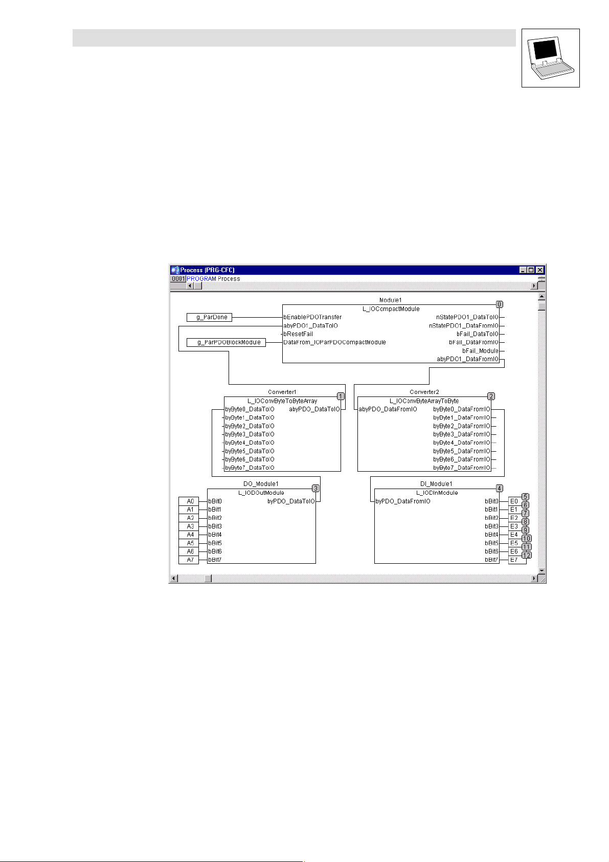
Programming the process data exchange between PLC and I/O system
The CFC editor is used to generate a program named Process.
· Declare an instance of function block L_IOCompactModule in Process.
· Generate two inputs in the CFC editor, assign names g_bParDone15 and g_ParData15 and
attach these to the corresponding inputs of function block L_IOCompactModule as shown in
the figure.
3−6
Several conversion blocks are available to evaluate input data and to transfer output data.
Function block L_IOCompactModule transmits output data to the I/O system and receives input
data from there.
LenzeIOSystem.lib EN 1.7
L
Page 17
Function library LenzeIOSystem.lib
Application examples
3.2 Compact decentralised I/O system
At input DataFrom_IOParPDO15, CAN communication relationships between PLC and I/O system
are transmitted from parameterisation block L_IOParCompactModule to process data block
L_IOCompactModule.
Process data transmission is started after parameterisation via a High signal at input
bEnablePDOTransfer.
Data conversion for evaluating individual channels
The program Process can be extended as follows:
· Use the menu command ExtrasÞOrder to indicate the sequence.
· Drag the individual function blocks to their positions in order to make the program sequence
comprehensible.
L
Function block L_IOCompactModule supplies the transmit and receive data as 8*8 byte information
via the CAN telegram.
The two converters convert the information into individual bits.
A digital input and output module maps the individual bits.
If the example for eight inputs / outputs is to be extended to 24 inputs, two further function blocks
L_IODInModule must be generated and linked via converter L_IOConvByteArrayToByte.
LenzeIOSystem.lib EN 1.7
3−7
Page 18

Function library LenzeIOSystem.lib
Application examples
3.2 Compact decentralised I/O system
Initialising the codes
Initialise the following codes in the PLC
· Code C0352
Subcode 0 = 1
Defines PLC as a CAN master so that the configuration enters the Operational state.
· Code C0356
Subcode 1 = 10000
Increases the boot−up time to10s
· Code C2104
Subcode 0 = 1
Starts the PLC program automatically after switching on the mains
3−8
LenzeIOSystem.lib EN 1.7
L
Page 19

Function library LenzeIOSystem.lib
4 Function blocks for parameterisation
This chapter contains information on function blocks for parameterisation.
The following functions and modules are parameterised:
· Monitoring function
· Analog input modules
· Analog output modules
· Counter modules
· Link between PLC control and I/O system
· Link between PLC control and compact module
Function blocks
L
LenzeIOSystem.lib EN 1.7
4−1
Page 20
Function library LenzeIOSystem.lib
Function blocks
4.1 L_IOParComGuarding − Monitoring function
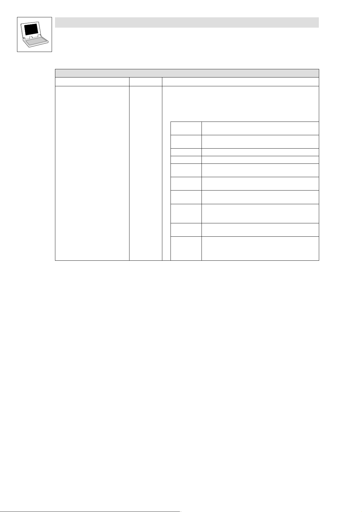
4.1 L_IOParComGuarding − Monitoring function
This function block parameterises, via the input setting, the monitoring functions provided by the I/O
system.
Included are
· NodeGuarding, Heartbeat and a Lenze−specific monitoring function,
· setting the output channels’ switching behaviour in the case of an error via input
byErrorBehavior.
The function block output indicates the transmission status.
L_IOParComGuarding
bExecute
byNodeAdr
tGuardTime
byLifeTimeFactor
tHeartbeatConsumerTime
byHearbeatConsumerAdr
tHeartbeatProducerTime
byErrorBehavior
tTimeOutPDO1_DataToIO
CTRL
EPM-T110
EPM-T111
Ixxxh
nState
tTimeOutPDO10_DataToIO
tTimeOutPDO1_DataFromIO
tTimeOutPDO10_DataFromIO
DataTo_IOData15
DataTo_IOData610
Note!
Use the FBs of LenzeCanDSxDrv.lib for evaluating the functions NodeGuarding and Heartbeat.
ð Inputs (Variable type: VAR_INPUT)
Variable name Data type Information/possible settings
bExecute Bool Execute write request
FALSE ä TRUE Write request is executed
byNodeAdr Byte Device address: 1 − 63
tGuardTime Time Nodeguarding: Time interval.
byLifeTimeFactor Byte Lifeguarding:
tHeartbeatConsumerTime Time Heartbeat: Monitoring interval.
byHeartbeatConsumerAdr Byte Node ID of the device to be monitored. (HeartbeatProducer Node ID)
An NMT master must poll the I/O system within the guard time period.
Default t = 0 ms
t = 0 − 65535 ms
Life Time Factor x Guard Time = Life Time.
Once this period has expired, the I/O system is switched into a predefined status.
The I/O system is switched into a predefined status if no telegram is received from
the Heartbeat Producer within this interval.
t = 0 − 65535 ms
4−2
LenzeIOSystem.lib EN 1.7
L
Page 21
Function library LenzeIOSystem.lib
Function blocks
4.1 L_IOParComGuarding − Monitoring function
(Variable type: VAR_INPUT)ð Inputs
Variable name Information/possible settingsData type
tHeartbeatProducerTime Time Set the transmission time for one heartbeat telegram t = 0 − 65535ms
byErrorBehavior Byte Set the bus status / behaviour on critical device error
0 Pre−Operational (default)
1 No status change
2 Stop
3 Reset after 2 seconds
tTimeOutPDO1_DataToIO
...
tTimeOutPDO10_DataToIO
tTimeOutPDO1_DataFromIO
...
tTimeOutPDO10_DataFromIO
Time Monitoring period for process input data (Lenze−specific).
If no data are received at the selected PDO within the monitoring period, the I/O
system assumes the status set under byErrorBehavior.
Default t = 0 ms
t = 0 − 65535 ms
Time Monitoring period for process output data.
If no data are transmitted from the I/O system to the PLC at the selected PDO within
the monitoring period, function block L_IODataXXX signals a time monitoring error.
Default t = 0 ms
t = 0 − 65535 ms
Outputs ð (Variable type: VAR_OUTPUT)
Identifier Data type Value/meaning
nState Integer States
DataTO_IOData15 Struct Structure for process data block L_IOData15.
DataTO_IOData610 Struct Structure for process data block L_IOData610
If a transmission error occurs during the parameterisation process, or the input data
are incorrect, the parameterisation process is aborted and an error number is
indicated at output nState.
Any errors are reset via an edge reversal at input bExecute or on program restart.
0 Transmit command is executed.
1 Transmit command sent − processing in process
2001 Error occurred during bus transfer
2002 Transmit command timed out
2004 Access denied − wrong target system: Subindex does not exist
2005 Access denied − wrong target system: Index does not exist
2013 Access denied − wrong target system: Invalid value range
2111 Access denied − wrong target system: More than 4 digits
specified after comma, or no fixed−comma−format index
2117 Communication channel does not exist − also refer Set byCom
channel
2120 Too many modules connected − parameter transfer aborted
−10xx Incorrect value at function block input.
XX := Number of faulty input (counting direction down),
parameterisation impossible.
Remedy: Change input value, restart data transmission
Transfer process output data monitoring periods to process data block L_IOData15.
Global struct−type variable
Transfer process output data monitoring periods to process data block
L_IOData610.
Global struct−type variable
L
LenzeIOSystem.lib EN 1.7
4−3
Page 22
Function library LenzeIOSystem.lib
Function blocks
4.2 L_IOParAlnModule − Parameterisation function
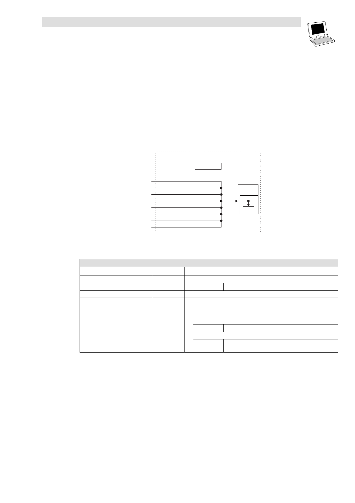
4.2 L_IOParAlnModule − Parameterisation function
By means of the L_IOParAInModule function block, the analog input modules (EPM−T310 / 311 /
T312) are parameterised. Parameterisation is started by a high edge on the input bExecute.
Each module has four channels, whereby each channel can be set individually.
The following is provided:
· Voltage measurement
· Current measurement
· Resistance measurement
· Temperature measurement
On the output of the function block, the transmission status and the information on the connected
modules are displayed.
L_IOParAInModule
bExecute
CTRL
nState
byNodeAdr
byAnalogModuleNo
BEnableDiagnosticAlarm *
bEnableAnalogInterrupt
byFunctionInput_CH1
BySampleRate_CH1 *
BySelectionFcn_CH1 *
ByHysteresis_CH1 *
ByTriggerSelection_CH1 *
ByTriggerValue_CH1 *
byFunctionInput_CH4
BySampleRate_CH4 *
BySelectionFcn_CH4 *
ByHysteresis_CH4 *
ByTriggerSelection_CH4 *
ByTriggerValue_CH4 *
*
Input/function is exclusively supported by type EPM−T310.
EPM-T110
EPM-T111
Ixxxh
4−4
LenzeIOSystem.lib EN 1.7
L
Page 23

Function library LenzeIOSystem.lib
Function blocks
4.2 L_IOParAlnModule − Parameterisation function
ð Inputs (Variable type: VAR_INPUT)
Variable name Data type Information/possible settings
bExecute BOOL Execute write request
FALSE ä TRUE Write request is executed
byNodeAdr Byte Device address: 1 − 63
byAnalogModuleNo Byte Slot number
bEnableDiagnosticAlarm BOOL
bEnableAnalogInterrupt BOOL
byFunctionInput_CH1
...
byFunctionInput_CH4
bySampleRate_CH1
...
bySampleRate_CH4
bySelectionFcn_CH1
...
bySelectionFcn_CH4
byHysterese_CH1
...
byHysterese_CH4
byTriggerSelection_CH1
...
byTriggerSelection_CH4
byTriggerValue_CH1
...
byTriggerValue_CH4
Byte
Byte
Byte
Byte
Byte
DWORD
· The analog module that is mounted first has the slot number 1.
· Maximally 16 analog modules can be attached.
Enable diagnostics alarm
TRUE Diagnostics alarm is enabled
Enable analog data transmission
TRUE Data transmission is enabled
Parameterise function
Default ±10V function code = 3B
^ 6−1
Select number of conversions per second
0 15 conversions
1 30 conversions
2 60 conversions
3 123 conversions
4 168 conversions
5 202 conversions
6 3.7 conversions
7 7.5 conversions
Selection
0 Selection deactivated
1 Use 2 of 3 values
2 Use 4 of 6 values
Hysteresis
0 Hysteresis deactivated
1 Hysteresis ±8
2 Hysteresis ±16
Transmission result
0 Use default settings
1 Upper limit value exceeded
2 Lower limit value not reached
3 Input value has changed by a defined value.
Value selection for a transmission event
2 Default
h
L
LenzeIOSystem.lib EN 1.7
4−5
Page 24
Function library LenzeIOSystem.lib
Function blocks
4.2 L_IOParAlnModule − Parameterisation function
Outputs ð (Variable type: VAR_OUTPUT)
Identifiers Data type Value/meaning
nState Integer
States
If a transmission error occurs during the parameterisation process or the input data
are incorrect, the parameterisation process is aborted and an error number is
indicated at output nState.
Errors are reset via an edge reversal at input bExecute or on
program restart.
0 Transmit request is executed.
The module is parameterised.
1 Transmit request dropped
Processing is running
2001 Error occurred during bus transfer
2002 Transmit request timed out
2004 Access denied
Incorrect target system: index does not exist
2005 Access denied
Incorrect target system: subindex does not exist
2013 Access denied
Incorrect target system: invalid value range
2111 Access denied
Incorrect target system: more than 4 decimal positions
specified or no fixed point format index
2117 Communication channel does not exist
byCom−Channelsetting
−10xx Incorrect value at function block input.
XX := number of the faulty input (counting direction
downwards), parameterisation impossible.
Remedy: change input value, restart data transmission
4−6
LenzeIOSystem.lib EN 1.7
L
Page 25
Function library LenzeIOSystem.lib
Function blocks
4.3 L_IOParAOutModule − Parameterisation function
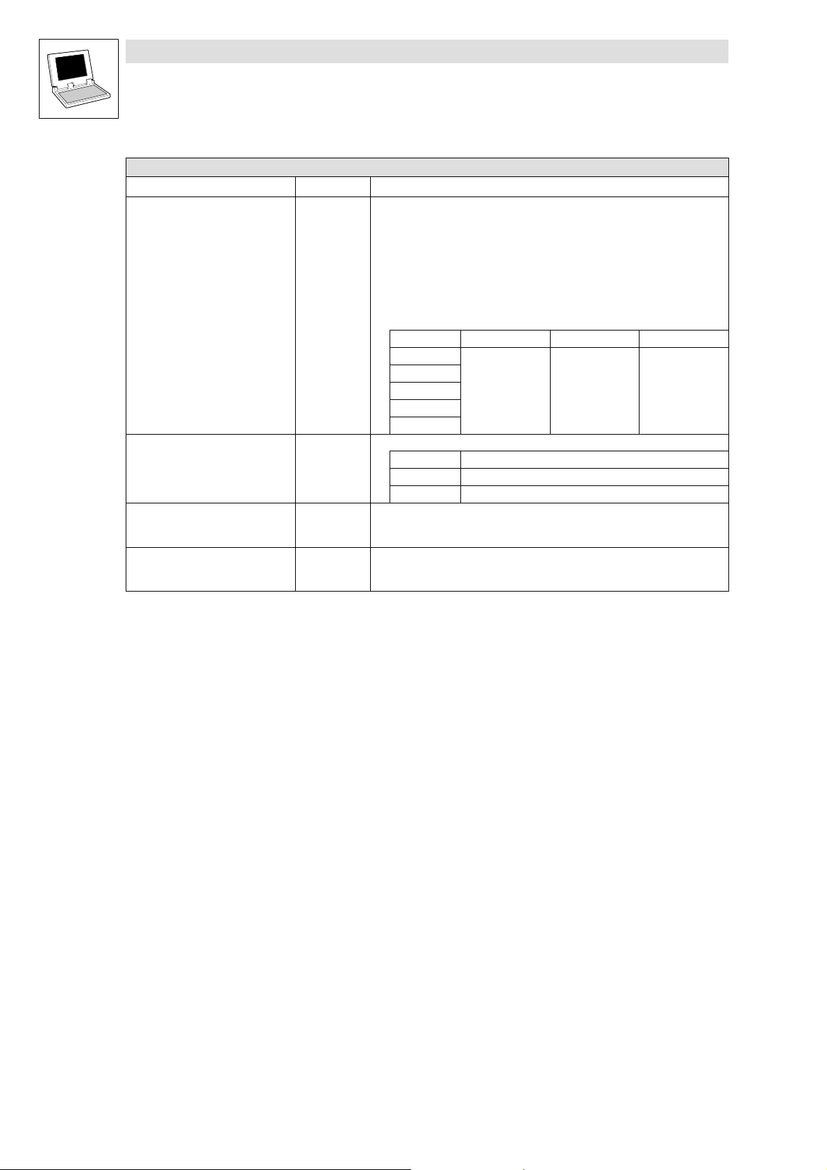
4.3 L_IOParAOutModule − Parameterisation function
By means of the L_IOParAOutModule function block, the analog output modules (EPM−T320 /
T321 / T322) are parameterised. Parameterisation is started by a high edge on the input bExecute.
Each module has four channels, whereby each channel can be set individually.
The following is provided:
· Voltage measurement
· Current measurement
The function block output indicates the transmission status.
L_IOParAOutModule
bExecute
byNodeAdr
byAnalogModuleNo
BEnableDiagnosticAlarm *
CTRL
nState
EPM-T110
EPM-T111
byFunctionOutput_CH1
byFunctionOutput_CH2
byFunctionOutput_CH3
byFunctionOutput_CH4
*
Input/function is exclusively supported by type EPM−T320.
ð Inputs (Variable type: VAR_INPUT)
Variable name Data type Information/possible settings
bExecute BOOL
byNodeAdr Byte Device address: 1 − 63
byAnalogModuleNo Byte Slot number
Execute write request
FALSE ä TRUE Write request is executed
· The analog module that is mounted first has the slot number 1.
· Maximally 16 analog modules can be attached.
bEnableDiagnosticAlarm BOOL
byFunctionOutput_CH1
...
byFunctionOutput_CH4
Byte
Enable diagnostics alarm
TRUE Diagnostics alarm is enabled
Parameterise function
Default ±10V function code = 01
^ 6−4
Ixxxh
h
L
LenzeIOSystem.lib EN 1.7
4−7
Page 26

Function library LenzeIOSystem.lib
Function blocks
4.3 L_IOParAOutModule − Parameterisation function
Outputs ð (Variable type: VAR_OUTPUT)
Identifiers Data type Value/meaning
nState Integer
States
If a transmission error occurs during the parameterisation process or the input data
are incorrect, the parameterisation process is aborted and an error number is
indicated at output nState.
Errors are reset via an edge reversal at input bExecute or on
program restart.
0 Transmit request is executed.
The module is parameterised.
1 Transmit request dropped
Processing is running
2001 Error occurred during bus transfer
2002 Transmit request timed out
2004 Access denied
Incorrect target system: subindex does not exist
2005 Access denied
Incorrect target system: index does not exist
2013 Access denied
Incorrect target system: invalid value range
2111 Access denied
Incorrect target system: more than 4 decimal positions
specified or no fixed point format index
2117 Communication channel does not exist
byCom−Channelsetting
−10xx Incorrect value at function block input.
XX := number of faulty input (counting direction down),
parameterisation impossible.
Remedy: change input variable, restart data transmission
4−8
LenzeIOSystem.lib EN 1.7
L
Page 27

Function library LenzeIOSystem.lib
Function blocks
4.4 L_IOParAlAOModule − Parameterisation function
4.4 L_IOParAlAOModule − Parameterisation function
Function block L_IOParAIAOModule parameterises the analog input and output modules
EPM−T330, a High edge at input bExecute starting the parameterisation process.
Every module has four channels that can each be set individually. Two analog inputs and two analog
outputs are available.
The following functions can be set:
· Voltage measuring
· Current measuring
· Voltage output
· Current output
The function block output indicates the transmission status and information on linked modules.
L_IOParAIAOModule
bExecute
CTRL
nState
byNodeAdr
byAnalogModuleNo
bEnableDiagnosticAlarm
bEnableAnalogInterrupt
byFunctionInput_CH1
bySampleRate_CH1
byFunctionInput_CH2
bySampleRate_CH2
byFunctionOutput_CH3
byFunctionOutput_CH4
EPM-T110
EPM-T111
Ixxxh
L
LenzeIOSystem.lib EN 1.7
4−9
Page 28

Function library LenzeIOSystem.lib
Function blocks
4.4 L_IOParAlAOModule − Parameterisation function
ð Inputs (Variable type: VAR_INPUT)
Variable name Data type Information/possible settings
bExecute Bool
byNodeAdr Byte Device address: 1 − 63
byAnalogModuleNo Byte Slot number
bEnableDiagnosticAlarm Bool
bEnableAnalogInterrupt Bool
byFunctionInput_CH1
...
byFunctionInput_CH2
bySampleRate_CH1
...
bySampleRate_CH2
byFunctionOutput_CH3
...
byFunctionOutput_CH4
Byte
Byte
Byte
Execute write request
FALSE ä TRUE Write request is executed
· The first analog module installed is assigned slot number 1.
· A maximum of 16 analog modules may be plugged.
Enable diagnostic alarm
Enable analog data transmission
Parameterise function
Select number of conversions per second
Parameterise function
TRUE Diagnostic alarm is enabled
TRUE Data transmission is enabled
Default ±10V function parameter = 01
^ 6−6
0 15 conversions
1 30 conversions
2 60 conversions
3 123 conversions
4 168 conversions
5 202 conversions
6 3.7 conversions
7 7.5 conversions
Default ±10V function code = 01
^ 6−6
h
h
4−10
LenzeIOSystem.lib EN 1.7
L
Page 29

Function library LenzeIOSystem.lib
Function blocks
4.4 L_IOParAlAOModule − Parameterisation function
Outputs ð (Variable type: VAR_OUTPUT)
Identifier Data type Value/meaning
nState Integer
States
If a transmission error occurs during the parameterisation process, or the input data
are incorrect, the parameterisation process is aborted and an error number is
indicated at output nState.
Any errors are reset via an edge reversal at input bExecute or on
program restart.
0 Transmit command is executed.
The module is parameterised.
1 Transmit command sent
Processing in process
2001 Error occurred during bus transfer
2002 Transmit command timed out
2004 Access denied
Wrong target system: Index does not exist
2005 Access denied
Wrong target system: Subindex does not exist
2013 Access denied
Wrong target system: Invalid value range
2111 Access denied
Wrong target system: More than 4 digits specified after
comma, or no fixed−comma−format index
2117 Communication channel does not exist
Set byCom channel
−10xx Incorrect value at function block input.
XX := Number of the faulty input (counting direction down),
parameterisation impossible.
Remedy: Change input value, restart data transmission
L
LenzeIOSystem.lib EN 1.7
4−11
Page 30

Function library LenzeIOSystem.lib
Function blocks
4.5 L_IOParSSIModule − Parameterisation function
4.5 L_IOParSSIModule − Parameterisation function
The SSI interface (SSI = Synchronous Serial Interface) is a synchronously clocked interface.
Function block L_IOParSSIModule converts the serial information of the measured values into
parallel information that is subsequently supplied to the control system.
L_IOParSSIModule
bExecute
byNodeAdr
byAnalogModuleNo
byFunction_Baudrate
bFunction_Code
bFunction_Hold
bFunction_SetDigitalOut
ð Inputs (Variable type: VAR_INPUT)
Variable name Data type Information/possible settings
bExecute Bool Execute write request
byNodeAdr Byte Device address: 1 − 63
byAnalogModuleNo Byte Slot number
CTRL
FALSE ä TRUE Write request is executed
· The first analog module installed is assigned slot number 1.
· A maximum of 9 modules may be plugged.
byFunction_Baudrate
bFunction_Code Bool Coding
bFunction_Hold Bool Hold function
bFunction_SetDigitalOut Bool Digital outputs
Byte Baud rate setting
0 300 kbps
1 100 kbps
2 300 kbps
3 600 kbps
4 300 kbps
Default 0 Binary code
1 Gray code
0 Not active
1 Active
0 Not active
1 Active
nState
EPM-T110
Ixxxh
4−12
LenzeIOSystem.lib EN 1.7
L
Page 31

Function library LenzeIOSystem.lib
Function blocks
4.5 L_IOParSSIModule − Parameterisation function
Outputs ð (Variable type: VAR_OUTPUT)
Identifier Data type Value/meaning
nState Integer States
If a transmission error occurs during the parameterisation process, or the input data
are incorrect, the parameterisation process is aborted and an error number is
indicated at output nState.
Any errors are reset via an edge reversal at input bExecute or on
program restart.
0 Transmit command is executed.
The module is parameterised.
1 Transmit command sent
Processing in process
2001 Error occurred during bus transfer
2002 Transmit command timed out
2004 Access denied
Wrong target system: Subindex does not exist
2005 Access denied
Wrong target system: Index does not exist
2013 Access denied
Wrong target system: Invalid value range
2111 Access denied
Wrong target system: More than 4 digits specified after
comma, or no fixed−comma−format index
2117 Communication channel does not exist
Set byCom channel
−10xx Incorrect value at function block input.
XX := Number of faulty input (counting direction down),
parameterisation impossible.
Remedy: Change input value, restart data transmission
L
LenzeIOSystem.lib EN 1.7
4−13
Page 32

Function library LenzeIOSystem.lib
Function blocks
4.6 L_IOParCounterModule − Counter function
4.6 L_IOParCounterModule − Counter function
The counter modules are parameterised via function block L_IOParCounterModule.
· The counter function is specified via inputs byFunction_CH1 and byFunction_CH2.
L_IOParCounterModule
bExecute
CTRL
nState
byNodeAdr
byAnalogModuleNr
byFunction_CH1
byFunction_CH2
ð Inputs (Variable type: VAR_INPUT)
Variable name Data type Information/possible settings
bExecute Bool Execute write request
FALSE ä TRUE Write request is executed
byNodeAdr Byte Device address: 1 − 63
byAnalogModuleNo Byte Slot number
· The first analog module installed is assigned slot number 1.
· A maximum of 16 analog modules may be plugged.
byFunction_CH1 Byte Parameterise function
Default (2 * 32 bit counters) function code 00
^ 6−10
byFunction_CH2 Byte Parameterise function
Default (2 * 32 bit counters) function code 00
^ 6−10
EPM-T110
Ixxxh
h
h
4−14
LenzeIOSystem.lib EN 1.7
L
Page 33

Function library LenzeIOSystem.lib
Function blocks
4.6 L_IOParCounterModule − Counter function
Outputs ð (Variable type: VAR_OUTPUT)
Identifier Data type Value/meaning
nState Integer States
If a transmission error occurs during the parameterisation process, or the input data
are incorrect, the parameterisation process is aborted and an error number is
indicated at output nState.
Any errors are reset via an edge reversal at input bExecute or on
program restart.
0 Transmit command is executed.
The module is parameterised.
1 Transmit command sent
Processing in process
2001 Error occurred during bus transfer
2002 Transmit command timed out
2004 Access denied
Wrong target system: Subindex does not exist
2005 Access denied
Wrong target system: Index does not exist
2013 Access denied
Wrong target system: Invalid value range
2111 Access denied
Wrong target system: More than 4 digits specified after
comma, or no fixed−comma−format index
2117 Communication channel does not exist
Set byCom channel
−10xx Incorrect value at function block input.
XX := Number of faulty input (counting direction down),
parameterisation impossible.
Remedy: Change input value, restart data transmission
L
LenzeIOSystem.lib EN 1.7
4−15
Page 34

Function library LenzeIOSystem.lib
Function blocks
4.7 L_IOParCounterDIModule − Counter function
4.7 L_IOParCounterDIModule − Counter function
The counter function of module EPM−T430 is parameterised via function block
L_IOParCounterDIModule.
· The counter function is specified via inputs byFunction_CH1.
L_IOParCounterDIModule
bExecute
CTRL
nState
byNodeAdr
byAnalogModuleNr
byFunction_CH1
ð Inputs (Variable type: VAR_INPUT)
Variable name Data type Information/possible settings
bExecute Bool Execute write request
FALSE ä TRUE Write request is executed
byNodeAdr Byte Device address: 1 − 63
byAnalogModuleNo Byte Slot number
· The first analog module installed is assigned slot number 1
· A maximum of 16 analog modules may be plugged.
byFunction_CH1 Byte Counter function
0 Fourfold pulse evaluation
1 Pulse and direction evaluation
2 Counter upwards / downwards
3 Frequency measuring
4 Period measuring
EPM-T110
Ixxxh
4−16
LenzeIOSystem.lib EN 1.7
L
Page 35

Function library LenzeIOSystem.lib
Function blocks
4.7 L_IOParCounterDIModule − Counter function
Outputs ð (Variable type: VAR_OUTPUT)
Identifier Data type Value/meaning
nState Integer States
If a transmission error occurs during the parameterisation process, or the input data
are incorrect, the parameterisation process is aborted and an error number is
indicated at output nState.
Any errors are reset via an edge reversal at input bExecute or on
program restart.
0 Transmit command is executed.
The module is parameterised.
1 Transmit command sent
Processing in process
2001 Error occurred during bus transfer
2002 Transmit command timed out
2004 Access denied
Wrong target system: Subindex does not exist
2005 Access denied
Wrong target system: Index does not exist
2013 Access denied
Wrong target system: Invalid value range
2111 Access denied
Wrong target system: More than 4 digits specified after
comma, or no fixed−comma−format index
2117 Communication channel does not exist
Set byCom channel
−10xx Incorrect value at function block input.
XX := Number of faulty input (counting direction down),
parameterisation impossible.
Remedy: Change input value, restart data transmission
L
LenzeIOSystem.lib EN 1.7
4−17
Page 36

Function library LenzeIOSystem.lib
Function blocks
4.8 L_IOParPDO15 − Parameterisation function
4.8 L_IOParPDO15 − Parameterisation function
This function block serves to set communication−relevant parameters between the PLC control and
the I/O system for PDO 1 − 5.
· Via 3 or 4 input values, a transmission/reception object is parameterised.
· The output nState displays the parameterisation status.
· Via the output DataTo_IOData15 , information is transferred to the L_IOData15 process data
block in a fixed structure.
L_IOParPDO15
bExecute_b
CTRL
byNodeAdr
bInitIOSystem
wCoID_RxPDO1
byTransmissionType_RxPDO1
tCycleTime_RxPDO1
nState
bParDone
wCoID_RxPDO5
byTransmissionType_RxPDO5
tCycleTime_RxPDO5
wCoID_TxPDO1
byTransmissionType_TxPDO1
tinhibitTime_TxPDO1
tCycleTime_RxPDO1
wCoID_TxPDO5
byTransmissionType_TxPDO5
tinhibitTime_TxPDO5
tCycleTime_RxPDO5
DataTo_IOData15
Internal function
bExecute_b = TRUE
Parameter data are transferred to the I/O system
bInitIOSystem = TRUE bInitIOSystem = FALSE
· Index 2358
initialisation of the I/O system.
· Waiting time 10s until initialisation has been completed.
If the boot−up time is >10s, the waiting time corresponds to the
boot−up time
.
is written for purposes of value acceptance or
hex
· Index 2358
initialisation of the I/O system.
hex
· Waiting time 10s until initialisation has been completed.
If the boot−up time is >10s, the waiting time corresponds to
the boot−up time
.
EPM-T110
EPM-T111
Ixxxh
is written for purposes of value acceptance or
4−18
State change of the I/O system by NMT telegram from the
controller:
Pre−operational ä Operational
LenzeIOSystem.lib EN 1.7
Parameterisation completed
L
Page 37

Function library LenzeIOSystem.lib
Function blocks
4.8 L_IOParPDO15 − Parameterisation function
Note!
Features and use of the L_IOParPDO15 FB.
· Use the L_IOParPDO15 FB last in a sequencer consisting of several FBs for parameterisation.
By means of the L_IOParPDO15 FB, parameterisation of the I/O system is carried out.
· For sending the NMT telegram, the controller has to be in the Operational CAN status,
therefore parameterise the controller as master. After the boot−up time has expired, the state
change from Pre−operational to Operational is automatically effected.
· If several IO systems (stations) are parameterised with standard values via the
L_IOParPDO15 FB on the system bus, an identifier collision between the individual PDOs of
these stations can occur. Therefore check the identifiers used.
After changing to the Operational CAN status, the current process image of the I/O system is sent.
ð Inputs (Variable type: VAR_INPUT)
Variable name Data type Information/possible settings
bExecute BOOL
byNodeAdr Byte Device address: 1 − 63
bInitIOSystem BOOL
wCobID_RxPDO1
...
wCobID_RxPDO5
byTransmissionType_RxPDO1
...
byTransmissionType_RxPDO5
tCycleTime_RxPDO1
...
tCycleTime_RxPDO5
WORD
Byte
Time Cycle time: t = 0 − 65535 ms
Execute write request
FALSE ä TRUE Write request is executed
Initialise I/O system after parameterisation
TRUE · Value acceptance by reset node
· I/O system is re−initialised, state change to Operational
FALSE · No value acceptance
· I/O system is not initialised
Setting identifiers
Default values: input wiring = 0
RxPDO = receive identifiers from the I/O system
Identifiers can be optionally set by value selection.
If the input wiring is "0", the identifiers are composed as follows.
Note!
The basic identifiers are not settled in the pre−assigned area of the standard system
bus.
ID range: 384−831
By this, crossovers of the ID with the free CAN objects which the IO−lib is based on
are avoided.
RxPDOX Identifier = Basic ID + Node address
RxPDO1 837 835 2
RxPDO2 840
RxPDO3 845
RxPDO4 850
RxPDO5 855
Transmission mode
0 Event−controlled
1 Time−controlled
2 Event−controlled with superimposed cycle time
L
LenzeIOSystem.lib EN 1.7
4−19
Page 38

Function library LenzeIOSystem.lib
Function blocks
4.8 L_IOParPDO15 − Parameterisation function
(Variable type: VAR_INPUT)ð Inputs
Variable name Information/possible settingsData type
wCobID_TxPDO1
...
wCobID_TxPDO5
byTransmissionType_TxPDO1
...
byTransmissionType_TxPDO5
tinhibitTime_TxPDO1
...
tinhibitTime_TxPDO5
tCycleTime_TxPDO1
...
tCycleTime_TxPDO5
WORD
Byte
Time Inhibit time: t = 0 − 65535 ms
Time Cycle time: t = 0 − 65535 ms
Setting identifiers
Default values: input wiring = 0
TxPDO = receive identifiers from the I/O system
Identifiers can be optionally set by value selection.
If the input wiring is "0", the identifiers are composed as follows.
Note!
The basic identifiers are not settled in the pre−assigned area of the standard system
bus.
ID range: 384−831
By this, crossovers of the ID with the free CAN objects which the IO−lib is based on
are avoided.
TxPDOX Identifier = Basic ID + Node address
TxPDO1 838 836 2
TxPDO2 841
TxPDO3 846
TxPDO4 851
TxPDO5 856
Transmission mode
0 Event−controlled
1 Time−controlled
2 Event−controlled with superimposed cycle time
4−20
LenzeIOSystem.lib EN 1.7
L
Page 39

Function library LenzeIOSystem.lib
Function blocks
4.8 L_IOParPDO15 − Parameterisation function
Outputs ð (Variable type: VAR_OUTPUT)
Identifiers Data type Value/meaning
nState Integer
nState Integer
bParDone BOOL
DataTO_IOData15 Struct Structure for the L_IOData15
States
If a transmission error occurs during the parameterisation process or the input data
are incorrect, the parameterisation process is aborted and an error number is
indicated at output nState.
Errors are reset via an edge reversal at input bExecute or on
program restart.
0 Transmit request is executed.
The module is parameterised.
1 Transmit request dropped
Processing is running
2001 Error occurred during bus transfer
2002 Transmit request timed out
2004 Access denied
Incorrect target system: index does not exist
2005 Access denied
Incorrect target system: subindex does not exist
2013 Access denied
Incorrect target system: invalid value range
2111 Access denied
Incorrect target system: More than 4 decimal positions
specified or no fixed point format index
2117 Communication channel does not exist
byCom−Channelsetting
−10xx Incorrect value at function block input.
XX := number of faulty input (counting direction down),
parameterisation impossible.
Remedy: change input variable, restart data transmission
States
If a transmission errors occur during the parameterisation process or the input data
are incorrect, the parameterisation process is aborted and an error number is
indicated at output nState.
Errors are reset via an edge reversal at input bExecute or on
program restart.
−150 Can bus is not in the "Operational" status.
−121 Incorrect driver number
−120 CAN driver for free CAN objects at present is not initialised.
−119 The transmit request memory is full.
The transmit request could not be entered anymore.
−118 No free CAN channel available.
−12 Message identifier is beyond the permissible range.
−11 pIOAddress pointer does not point to PLC−RAM.
0 Transmit or reception request has been carried out.
1 Request has not yet been completed and still is available in
the request memory.
10 Telegram length is greater than 8 bytes.
Telegram length is limited to 8 bytes.
200 Data in the reception memory have been overwritten.
Parameterisation
TRUE Parameterisation completed
process data block
Global variable of the "Struct" type
L
LenzeIOSystem.lib EN 1.7
4−21
Page 40

Function library LenzeIOSystem.lib
Function blocks
4.9 L_IOParPDO610 − Parameterisation function
4.9 L_IOParPDO610 − Parameterisation function
This function block serves to set communication−relevant parameters between the PLC control and
the I/O system for PDO 6 − 10.
· Via 3 or 4 input values, a transmission/reception object is parameterised.
· The output nState display the parameterisation status.
· Via the output DataTo_IOData610, information is transferred to the L_IOData610 process data
block in a fixed structure.
L_IOParPDO610
bExecute_b
CTRL
byNodeAdr
bInitIOSystem
wCobID_RxPDO6
byTransmissionType_RxPDO6
tCycleTime_RxPDO6
nState
bParDone
wCobID_RxPDO10
byTransmissionType_RxPDO10
tCycleTime_RxPDO10
wCobID_TxPDO6
byTransmissionType_TxPDO6
tinhibitTime_TxPDO6
tCycleTime_RxPDO6
wCobID_TxPDO10
byTransmissionType_TxPDO10
tinhibitTime_TxPDO10
tCycleTime_RxPDO10
DataTo_IOData610
Internal function
bExecute_b = TRUE
Parameter data is transferred to the I/O system
bInitIOSystem = TRUE bInitIOSystem = FALSE
· Index 2358
is written for purposes of value acceptance or initialisation of
the I/O system.
· Waiting time 10s until initialisation has been completed.
If the boot−up time is >10s, the waiting time corresponds to the
boot−up time
.
hex
· Index 2358
initialisation of the I/O system.
hex
· Waiting time 10s until initialisation has been completed.
If the boot−up time is >10s, the waiting time corresponds to
the boot−up time
.
EPM-T110
EPM-T111
Ixxxh
is written for purposes of value acceptance or
4−22
State change of the I/O system by NMT telegram from the
controller:
Pre−operational ä Operational
LenzeIOSystem.lib EN 1.7
Parameterisation completed
L
Page 41

Function library LenzeIOSystem.lib
Function blocks
4.9 L_IOParPDO610 − Parameterisation function
Note!
Features and use of the L_IOParPDLO610 FB.
· Use the L_IOParPDO610 FB last in a sequencer consisting of several FBs for
parameterisation. By means of the L_IOParPDO610 FB, parameterisation of the I/O system is
carried out.
· Parameterise the controller as master.
After the boot−up time has expired, for the master the change from the Pre−operational to the
Operational status is effected automatically.
· For sending the NMT telegram, the controller has to be in the Operational CAN status.
· If several IO systems (stations) are parameterised with standard values via the
L_IOParPDO610 FB on the system bus, an identifier collision between the individual PDOs of
these stations can occur. Therefore check the identifiers used.
After changing to the Operational CAN status, the current process image of the I/O system is sent.
ð Inputs (Variable type: VAR_INPUT)
Variable name Data type Information/possible settings
bExecute BOOL Execute write request
FALSE ä TRUE Write request is executed
byNodeAdr Byte Device address: 1 − 63
bInitIOSystem BOOL
wCobID_RxPDO6
...
wCobID_RxPDO10
byTransmissionType_RxPDO6
...
byTransmissionType_RxPDO10
tCyceTime_RxPDO6
...
tCyceTime_RxPDO10
WORD
Byte
Time Cycle time: t = 0 − 65535 ms
Initialise I/O system after parameterisation
TRUE · Value acceptance by reset node
FALSE · No value acceptance
· I/O system is not initialised
Setting identifiers
Default values: input wiring = 0
RxPDO = receive identifiers from the I/O system
Identifiers can be optionally set by value selection.
If the input wiring is "0", the identifiers are composed as follows.
Note: The basic identifiers are not settled in the pre−assigned area of the standard
system bus.
ID range: 384−831
By this, crossovers of the ID with the free CAN objects which the IO−lib is based on
are avoided.
RxPDOX Identifier = Basic ID + Node address
RxPDO6 862 860 2
RxPDO7 865
RxPDO8 870
RxPDO9 875
RxPDO10 880
Transmission mode
0 Event−controlled
1 Time−controlled
2 Event−controlled with superimposed cycle time
L
LenzeIOSystem.lib EN 1.7
4−23
Page 42
Function library LenzeIOSystem.lib
Function blocks
4.9 L_IOParPDO610 − Parameterisation function
(Variable type: VAR_INPUT)ð Inputs
Variable name Information/possible settingsData type
wCobID_TxPDO6
...
wCobID_TxPDO10
byTransmissionType_TxPDO6
...
byTransmissionType_TxPDO10
tinhibitTime_TxPDO6
...
tinhibitTime_TxPDO10
tCyceTime_TxPDO6
...
tCyceTime_TxPDO10
WORD
Byte
Time Inhibit time: t = 0 − 65535 ms
Time Cycle time: t = 0 − 65535 ms
Setting identifiers
Default values: input wiring = 0
TxPDO = receive identifiers from the I/O system
Identifiers can be optionally set by value selection.
If the input wiring is "0", the identifiers are composed as follows.
Note: The basic identifiers are not settled in the pre−assigned area of the standard
system bus.
ID range: 384−831
By this, crossovers of the ID with the free CAN objects which the IO−lib is based on
are avoided.
Transmission mode
TxPDOX Identifier = Basic ID + Node address
TxPDO6 863 861 2
TxPDO7 866
TxPDO8 871
TxPDO9 876
TxPDO10 881
0 Event−controlled
1 Time−controlled
2 Event−controlled with superimposed cycle time
4−24
LenzeIOSystem.lib EN 1.7
L
Page 43

Function library LenzeIOSystem.lib
Function blocks
4.9 L_IOParPDO610 − Parameterisation function
Outputs ð (Variable type: VAR_OUTPUT)
Identifiers Data type Value/meaning
nState integer
nState integer
bParDone BOOL
DataTO_IOData610 Struct Structure for the L_IOData610
States
If a transmission error occurs during the parameterisation process or the input data
are incorrect, the parameterisation process is aborted and an error number is
indicated at output nState.
Errors are reset via an edge reversal at input bExecute or on
program restart.
0 Transmit request is executed.
The module is parameterised.
1 Transmit request dropped
Processing is running
2001 Error occurred during bus transfer
2002 Transmit request timed out
2004 Access denied
Incorrect target system: index does not exist
2005 Access denied
Incorrect target system: subindex does not exist
2013 Access denied
Incorrect target system: invalid value range
2111 Access denied
Incorrect target system: More than 4 decimal positions
specified or no fixed point format index
2117 Communication channel does not exist
byCom−Channelsetting
−10xx Incorrect value at function block input.
XX := number of faulty input (counting direction down),
parameterisation impossible.
Remedy: change input variable, restart data transmission
States
If a transmission error occurs during the parameterisation process or the input data
are incorrect, the parameterisation process is aborted and an error number is
indicated at output nState.
Errors are reset via an edge reversal at input bExecute or on
program restart.
−150 Can bus is not in the "Operational" status.
−121 Incorrect driver number
−120 CAN driver for free CAN objects at present is not initialised.
−119 The transmit request memory is full.
The transmit request could not be entered anymore.
−118 No free CAN channel available.
−12 Message identifier is beyond the permissible range.
−11 pIOAddress pointer does not point to PLC−RAM.
0 Transmit or reception request has been carried out.
1 Request has not yet been completed and still is available in
the request memory.
10 Telegram length is greater than 8 bytes.
Telegram length is limited to 8 bytes.
200 Data in the reception memory have been overwritten.
Parameterisation
TRUE Parameterisation completed
process data block
Global variable of the "Struct" type
L
LenzeIOSystem.lib EN 1.7
4−25
Page 44

Function library LenzeIOSystem.lib
Function blocks
4.10 L_IOParCompactModule − Parameterisation function
4.10 L_IOParCompactModule − Parameterisation function
This function block assists in the setting of parameters relevant to PLC control compact module
communication.
· Parameterising a function for process data exchange time monitoring.
· Output nState indicates the parameterisation process status.
· Use output DataTo_IODataBlockModule to transfer fixed−structure information to process data
block L_IOCompactModule.
L_IOParCompactModule
bExecute_b
CTRL
nState
bParDone
byNodeAdr
bInitIOSystem
byErrorBehavior
tTimeOutPDO1_DataToIO
tTimeOutPDO1_DataFromIO
wCobID_RxPDO1
byTransmissionType_RxPDO1
tCycleTime_RxPDO1
wCobID_TxPDO1
byTransmissionType_TxPDO1
tinhibitTime_TxPDO1
tCycleTime_RxPDO1
ð Inputs (Variable type: VAR_INPUT)
Variable name Data type Information/possible settings
bExecute Bool Execute write request
FALSE ä TRUE Write request is executed
byNodeAdr Byte Device address: 1 − 63
bInitIOSystem Bool Initialise I/O system after parameterisation
DataTo_IODataBlockModule
EPM-T8xx
Ixxxh
TRUE · Value accepted via Reset Node
· I/O system is reinitialised, status changes to OPERATIONAL
FALSE · No value accepted
· I/O system is not initialised
byErrorBehavior Byte Set the bus states
tTimeOutPDO1_DataToIO Time Monitoring period for process input data (Lenze−specific).
tTimeOutPDO1_DataFromIO Time Monitoring period for process output data.
Behaviour during a critical device error
0 Pre−Operational
1 No status change
2 Stop
3 Reset after 2 seconds
If no data are received at the selected PDO within the monitoring period, the I/O
system assumes the state set under byErrorBehavior.
Default t = 0 ms (monitoring off)
t = 0 − 65535 ms
If no data are transmitted from the I/O system to the PLC at the selected PDO within
the monitoring period, function block l_IODataXXX signals a time monitoring error.
Default t = 0 ms (monitoring off)
t = 0 − 65535 ms
4−26
LenzeIOSystem.lib EN 1.7
L
Page 45

Function library LenzeIOSystem.lib
Function blocks
4.10 L_IOParCompactModule − Parameterisation function
(Variable type: VAR_INPUT)ð Inputs
Variable name Information/possible settingsData type
wCobID_RxPDO1 Word Set identifiers
byTransmissionType_RxPDO1
tCyceTime_TxPDO6
...
tCyceTime_TxPDO10
wCobID_TxPDO1 Word Set identifiers
byTransmissionType_TxPDO1
tInhibitTime_TxPDO6
...
tInhibitTime_TxPDO10
tCyceTime_TxPDO6
...
tCyceTime_TxPDO10
Byte Transmission method
Time Cycle time t = 0 − 65535 ms
Byte Transmission method
Time Inhibit time t = 0 − 65535 ms
Time Cycle time t = 0 − 65535 ms
Default values: Input setting = 0
RxPDO = I/O system receive identifiers
Identifiers can be given any setting with a specified value.
The identifiers are composed as follows if the input setting = 0.
Note!
The basic identifiers are outside the preassigned standard system bus range.
ID range: 384−831
This prevents IDs from coinciding with unassigned CAN objects on which the IO−lib is
based.
RxPDOX Identifier = Basic ID + Node address
RxPDO1 837 835 2
0 Event−controlled
1 Time−controlled
2 Event−controlled with superimposed cycle time
Default values: Input setting = 0
TxPDO = I/O system receive identifiers
Identifiers can be given any setting with a specified value.
The identifiers are composed as follows if the input setting = 0.
The basic identifiers are outside the preassigned standard system bus range.
ID range: 384−831
This prevents IDs from coinciding with unassigned CAN objects on which the IO−lib is
based.
TxPDOX Identifier = Basic ID + Node address
TxPDO1 838 836 2
0 Event−controlled
1 Time−controlled
2 Event−controlled with superimposed cycle time
L
LenzeIOSystem.lib EN 1.7
4−27
Page 46

Function library LenzeIOSystem.lib
Function blocks
4.10 L_IOParCompactModule − Parameterisation function
Outputs ð (Variable type: VAR_OUTPUT)
Identifier Data type Value/meaning
nState Integer States
nState
bParDone Byte Parameterisation status
DataTO_IODataCompactmodule Struct Structure for process data block L_IOCompactModule
Integer States
If a transmission error occurs during the parameterisation process, or the input data
are incorrect, the parameterisation process is aborted and an error number is
indicated at output nState.
Any errors are reset via an edge reversal at input bExecute or on
program restart.
If a transmission error occurs during the parameterisation process, or the input data
are incorrect, the parameterisation process is aborted and an error number is
indicated at output nState.
Any errors are reset via an edge reversal at input bExecute or on
program restart.
Global struct−type variable
0 Transmit command is executed.
The module is parameterised.
1 Transmit command sent
Processing in process
2001 Error occurred during bus transfer
2002 Transmit command timed out
2004 Access denied
Wrong target system: Index does not exist
2005 Access denied
Wrong target system: Subindex does not exist
2013 Access denied
Wrong target system: Invalid value range
2111 Access denied
Wrong target system: More than 4 digits specified after
comma, or no fixed−comma−format index
2117 Communication channel does not exist
Set byCom channel
−10xx Incorrect value at function block input.
XX := Number of faulty input (counting direction down),
parameterisation impossible.
Remedy: Change input value, restart data transmission
−150 CAN bus not in Operational status.
−121 Wrong driver number
−120 CAN driver for unassigned CAN objects currently not initialised.
−119 Transmit command memory is full.
Transmit command could not be entered.
−118 No free CAN channel available.
−12 Message identifier outside permissible range.
−11 pIOAddress pointer does not point at PLC RAM.
0 Transmit and/or receive command is executed.
1 Command has not yet been completed and is still in the
command memory.
10 Telegram longer than 8 bytes.
Telegram length limited to 8 bytes.
200 Data in receive memory have been overwritten.
TRUE Parameterisation executed
4−28
LenzeIOSystem.lib EN 1.7
L
Page 47

Function library LenzeIOSystem.lib
Function blocks
5 Function blocks for process data processing
This chapter contains information on function blocks for coordination, support and conversion.
The following functions and modules are coordinated:
· Digital and analog input and output data
The following functions and modules are supported:
· Analog input modules
· Analog output modules
· Counter modules
· Link between PLC control and I/O system
· Link between PLC control and compact module
L
LenzeIOSystem.lib EN 1.7
5−1
Page 48

Function library LenzeIOSystem.lib
Function blocks
5.1 L_IOData15 − Coordinate data
5.1 L_IOData15 − Coordinate data
Function block L_IOData15 coordinates digital and analog input and/or output data.
The block represents the interface between PLC and I/O system.
· Via inputs abyPDO_DataToIO, data are transmitted from the control to the I/O system
(digital/analog output channels).
· The states of the digital and analog input channels are transmitted to the control via outputs
abyPDO_DataFromIO.
· This function block is made up of unassigned CAN objects so that the status display at
outputs nState... is the same as for the CAN library’s transmit and receive blocks.
L_IOData15
bEnablePDOTransfer
bResetFail
DataFrom_IOParPDO15
DataFrom_IOParComGuarding
EPM-T110
abyPDO1_DataToIO
abyPDO5_DataToIO
EPM-T111 EPM-T111
RxPDO1
RxPDO2
RxPDO3
RxPDO4
RxPDO5
CTRL
EPM-T110
TxPDO1
TxPDO2
TxPDO3
TxPDO4
TxPDO5
nStatePDO1_DataToIO
nStatePDO5_DataToIO
nStatePDO1_DataFromIO
nStatePDO5_DataFromIO
bFail_DataToIO
bFail_DataFromIO
bFailModule
abyPDO1_DataFromIO
abyPDO5_DataFromIO
5−2
LenzeIOSystem.lib EN 1.7
L
Page 49

Function library LenzeIOSystem.lib
Function blocks
5.1 L_IOData15 − Coordinate data
ð Inputs (Variable type: VAR_INPUT)
Variable name Data type Information/possible settings
bEnablePDOTransfer Bool Data transfer
TRUE PDO data transfer active
abyPDO1_DataToIO
...
abyPDO5_DataToIO
bResetFail Bool Reset output data bFail_DataToIO. bFail_DataFromIO and bFail_Module
DataFrom_IOParPDO15 Struct Structural data of parameter block L_IOParPDO15 are transferred to process data
DataFrom_IOParComGuarding Struct Transfer monitoring times tTimeOut_DataFromIO for PDO 1−5.
Outputs ð (Variable type: VAR_OUTPUT)
Identifier Data type Value/meaning
nStatePDO1_DataFromIO
...
nStatePDO5_DataFromIO
Byte array I/O system receive objects
· Transfer process data from PLC to I/O system
(digital/analog outputs)
TRUE Output data reset
block L_IOData15 via this input.
Global struct−type variable
Structural data of parameter block L_IOParComGuading.
Global struct−type variable
Integer States
If a transmission error occurs during the parameterisation process, or the input data
are incorrect, the parameterisation process is aborted and an error number is
indicated at output nState.
−150 CAN bus not in Operational status.
−121 Wrong driver number
−120 CAN driver for unassigned CAN objects currently not initialised.
−119 Transmit command memory is full.
Transmit command could not be entered.
−118 No free CAN channel available.
−12 Message identifier outside permissible range.
−11 pIOAddress pointer does not point at PLC RAM.
0 Transmit and/or receive command is executed.
1 Command has not yet been completed and is still in the
command memory.
2 Data transmission disabled
· bEnablePDOTransfer = False
· I/O system parameterisation not yet complete
10 Telegram longer than 8 bytes.
Telegram length limited to 8 bytes.
200 Data in receive memory have been overwritten.
−30xx TimeOut monitoring (xx @ PDOxx)
Data transfer from I/O system to PLC failed.
Data arrived late or not at all.
L
LenzeIOSystem.lib EN 1.7
5−3
Page 50

Function library LenzeIOSystem.lib
Function blocks
5.1 L_IOData15 − Coordinate data
(Variable type: VAR_OUTPUT)Outputs ð
Identifier Value/meaningData type
nStatePDO1_DataToIO
...
nStatePDO5_DataToIO
bFail_DataToIO Bool Transmit command to I/O system
bFail_DataFromIO Bool Receive command from I/O system
bFail_Module Bool Module error
abyPDO1_DataFromIO
...
abyPDO5_DataFromIO
Integer States
If a transmission error occurs during the parameterisation process, or the input data
are incorrect, the parameterisation process is aborted and an error number is
indicated at output nState.
−150 CAN bus not in Operational status.
−121 Wrong driver number
−120 CAN driver for unassigned CAN objects currently not initialised.
−119 Transmit command memory is full.
Transmit command could not be entered.
−118 No free CAN channel available.
−12 Message identifier outside permissible range.
−11 pIOAddress pointer does not point at PLC RAM.
0 Transmit and/or receive command is executed.
1 Command has not yet been completed and is still in the
command memory.
2 Data transmission disabled
· bEnablePDOTransfer = False
· I/O system parameterisation not yet complete
10 Telegram longer than 8 bytes.
Telegram length limited to 8 bytes.
200 Data in receive memory have been overwritten.
TRUE Transmit command to I/O system is not correct
TRUE Receive command from I/O system is not correct
TRUE · Module diagnostics active
· Emergency object indicates error
Byte array I/O system transmit objects
Transfer process data from I/O system to PLC
(digital/analog inputs)
5−4
LenzeIOSystem.lib EN 1.7
L
Page 51

Function library LenzeIOSystem.lib
Function blocks
5.2 L_IOData610 − Coordinate data
5.2 L_IOData610 − Coordinate data
Function block L_IOData610 coordinates digital and analog input and/or output data for process
data objects 6 − 10.
The block represents the interface between PLC and I/O system.
· Via inputs abyPDO_DataToIO, data are transmitted from the control to the I/O system
(digital/analog output channels).
· The states of the digital and analog input channels are transmitted to the control via outputs
abyPDO_DataFromIO.
· This function block is made up of unassigned CAN objects so that the status display at
outputs nState... is the same as for the CAN library’s transmit and receive blocks.
L_IOParPDO610
bExecute_b
CTRL
byNodeAdr
bInitIOSystem
nState
bParDone
wCobID_RxPDO6
byTransmissionType_RxPDO6
tCycleTime_RxPDO6
wCobID_RxPDO10
byTransmissionType_RxPDO10
tCycleTime_RxPDO10
wCobID_TxPDO6
byTransmissionType_TxPDO6
tinhibitTime_TxPDO6
tCycleTime_RxPDO6
wCobID_TxPDO10
byTransmissionType_TxPDO10
tinhibitTime_TxPDO10
tCycleTime_RxPDO10
ð Inputs (Variable type: VAR_INPUT)
Variable name Data type Information/possible settings
bEnablePDOTransfer Bool Data transfer
TRUE PDO data transfer active
abyPDO6_DataToIO
...
abyPDO10_DataToIO
bResetFail Bool Reset output data bFail_DataToIO and bFail_DataFromIO
DataFrom_IOParPDO610 Struct Structural data of parameter block L_IOParPDO610 are transferred to process data
DataFrom_IOParComGuarding Struct Transfer monitoring times tTimeOut_DataFromIO for PDO 6−10.
Byte array I/O system receive objects
· Transfer process data from PLC to I/O system
(digital/analog outputs)
TRUE Output data reset
block L_IOData610 via this input.
Global struct−type variable
Structural data of parameter block L_IOParComGuarding.
Global struct−type variable
EPM-T110
EPM-T111
Ixxxh
DataTo_IOData610
L
LenzeIOSystem.lib EN 1.7
5−5
Page 52

Function library LenzeIOSystem.lib
Function blocks
5.2 L_IOData610 − Coordinate data
Outputs ð (Variable type: VAR_OUTPUT)
Identifier Data type Value/meaning
nStatePDO6_DataToIO
...
nStatePDO10_DataToIO
Integer States
If a transmission error occurs during the parameterisation process, or the input data
are incorrect, the parameterisation process is aborted and an error number is
indicated at output nState.
−150 CAN bus not in Operational status.
−121 Wrong driver number
−120 CAN driver for unassigned CAN objects currently not initialised.
−119 Transmit command memory is full.
Transmit command could not be entered.
−118 No free CAN channel available.
−12 Message identifier outside permissible range.
−11 pIOAddress pointer does not point at PLC RAM.
0 Transmit and/or receive command is executed.
1 Command has not yet been completed and is still in the
command memory.
2 Data transmission disabled
· bEnablePDOTransfer = False
· I/O system parameterisation not yet complete
10 Telegram longer than 8 bytes.
Telegram length limited to 8 bytes.
200 Data in receive memory have been overwritten.
5−6
LenzeIOSystem.lib EN 1.7
L
Page 53

Function library LenzeIOSystem.lib
Function blocks
5.2 L_IOData610 − Coordinate data
(Variable type: VAR_OUTPUT)Outputs ð
Identifier Value/meaningData type
nStatePDO6_DataFromIO
...
nStatePDO10_DataFromIO
bFail_DataToIO Bool Transmit command to I/O system
bFail_DataFromIO Bool Receive command from I/O system
abyPDO6_DataFromIO
...
abyPDO10_DataFromIO
Integer States
If a transmission error occurs during the parameterisation process, or the input data
are incorrect, the parameterisation process is aborted and an error number is
indicated at output nState.
−150 CAN bus not in Operational status.
−121 Wrong driver number
−120 CAN driver for unassigned CAN objects currently not initialised.
−119 Transmit command memory is full.
Transmit command could not be entered.
−118 No free CAN channel available.
−12 Message identifier outside permissible range.
−11 pIOAddress pointer does not point at PLC RAM.
0 Transmit and/or receive command is executed.
1 Command has not yet been completed and is still in the
command memory.
2 Data transmission disabled
· bEnablePDOTransfer = False
· I/O system parameterisation not yet complete
10 Telegram longer than 8 bytes.
Telegram length limited to 8 bytes.
200 Data in receive memory have been overwritten.
−30xx TimeOut monitoring (xx @ PDOxx)
Data transfer from I/O system to PLC failed.
Data arrived late or not at all.
TRUE Transmit command to I/O system is not correct
TRUE Receive command from I/O system is not correct
Byte array I/O system transmit objects
Transfer process data from I/O system to PLC
(digital/analog inputs)
L
LenzeIOSystem.lib EN 1.7
5−7
Page 54

Function library LenzeIOSystem.lib
Function blocks
5.3 L_IOCompactModule − Coordinate data
5.3 L_IOCompactModule − Coordinate data
Function block L_IOCompactModule supplies the digital input and/or output data of the I/O system
and is used for compact module EPM−T83X.
The block represents the interface between PLC and I/O system.
· Via inputs abyPDO_DataToIO, data are transmitted from the control to the I/O system
(digital/analog output channels).
· The states of the digital and analog input channels are transmitted to the control via outputs
abyPDO_DataFromIO.
· This function block is made up of unassigned CAN objects so that the status display at
outputs nState... is the same as for the CAN library’s transmit and receive blocks.
L_IODataCompactModule
bEnablePDOTransfer nStatePDO1_DataToIO
bResetFail
DataFrom_IOParPDOBlockModule
EPM-T110
abyPDO1_DataToIO
RxPDO1
ð Inputs (Variable type: VAR_INPUT)
Variable name Data type Information/possible settings
bEnablePDOTransfer Bool Data transfer
abyPDO1_DataToIO Byte array I/O system receive object
CTRL
nStatePDO1_DataFromIO
bFail_DataToIO
bFail_DataFromIO
bFail_Module
EPM-T110
abyPDO1_DataFromIO
TxPDO1
TRUE PDO data transfer active
· Transfer process data from PLC to I/O system
(digital outputs)
bResetFail Bool Reset output data bFail_DataToIO, bFail_DataFromIO and bFail_Module
TRUE Output data reset
DataFrom_IOParPDOCompactModule Struct Structural data of parameter block L_IOParPDOCompaktModule.
Global struct−type variable.
5−8
LenzeIOSystem.lib EN 1.7
L
Page 55

Function library LenzeIOSystem.lib
Function blocks
5.3 L_IOCompactModule − Coordinate data
Outputs ð (Variable type: VAR_OUTPUT)
Identifier Data type Value/meaning
nStatePDO1_DataToIO Integer States
nStatePDO1_DataFromIO Integer States
Indicates actual status of the transmit objects.
−150 CAN bus not in Operational status.
−121 Wrong driver number
−120 CAN driver for unassigned CAN objects currently not initialised.
−119 Transmit command memory is full.
Transmit command could not be entered.
−118 No free CAN channel available.
−12 Message identifier outside permissible range.
−11 pIOAddress pointer does not point at PLC RAM.
0 Transmit and/or receive command is executed.
1 Command has not yet been completed and is still in the
command memory.
2 Data transmission disabled
· bEnablePDOTransfer = False
· I/O system parameterisation not yet complete
10 Telegram longer than 8 bytes.
Telegram length limited to 8 bytes.
200 Data in receive memory have been overwritten.
Indicates actual status of the receive objects.
−150 CAN bus not in Operational status.
−121 Wrong driver number
−120 CAN driver for unassigned CAN objects currently not initialised.
−119 Transmit command memory is full.
Transmit command could not be entered.
−118 No free CAN channel available.
−12 Message identifier outside permissible range.
−11 pIOAddress pointer does not point at PLC RAM.
0 Transmit and/or receive command is executed.
1 Command has not yet been completed and is still in the
command memory.
2 Data transmission disabled
· bEnablePDOTransfer = False
· I/O system parameterisation not yet complete
10 Telegram longer than 8 bytes.
Telegram length limited to 8 bytes.
200 Data in receive memory have been overwritten.
−30xx TimeOut monitoring
Data transfer from I/O system to PLC failed.
Data arrived late or not at all.
L
LenzeIOSystem.lib EN 1.7
5−9
Page 56

Function library LenzeIOSystem.lib
Function blocks
5.3 L_IOCompactModule − Coordinate data
(Variable type: VAR_OUTPUT)Outputs ð
Identifier Value/meaningData type
bFail_DataToIO Bool Transmit command to I/O system
bFail_DataFromIO Bool Receive command from I/O system
bFail_Module Bool Module error
abyPDO1_DataFromIO Byte array I/O system transmit object
TRUE Transmit command to I/O system is not correct
TRUE Receive command from I/O system is not correct
TRUE · Module diagnostics active
· Emergency object indicates error
Transfer process data from I/O system to PLC
(digital inputs)
5−10
LenzeIOSystem.lib EN 1.7
L
Page 57

Function library LenzeIOSystem.lib
Function blocks
5.4 L_IOCounterDataToIO − Counter function
5.4 L_IOCounterDataToIO − Counter function
The counter module function is set via parameterisation data block
L_IOParCounterDataToIO. Depending on this parameterisation, the counter may be preassigned
values for counting or comparison. Function block L_IOCounterDataToIO is used for this
preassignment.
L_IOCounterDataToIO
byByte0_Counter02
byByte1_Counter02
byByte2_Counter01
byByte3_Counter01
byByte4_Counter12
byByte5_Counter12
byByte6_Counter11
byByte7_Counter11
Byte
Byte
Byte
Byte
Byte
Byte
Byte
Byte
Byte
DI
0
DI
1
DI
2
DI
3
DI
3
DI
5
DI
6
DI
DI
7
7
abyPDO_DataToIO
byByte8_Control
byByte9_Status
Byte
Byte
DI
1
DI
0
abyPDO_DataToIO
Assignment of bytes 0...7 is dependent on the selected mode.
The counter mode default value is zero, resulting in the following assignment.
· Counter 0 preassignment with counting values is assisted by inputs
– byByte0_Counter02 LowByte Bit16...23
– byByte1_Counter02 HighByte Bit24...32
– byByte2_Counter01 LowByte Bit0...7
– byByte3_Counter01 HighByte Bit8...15
· Setting of respective values for counter 1 is via inputs
– byByte4_Counter12 LowByte Bit16...23
– byByte5_Counter12 HighByte Bit24...32
– byByte6_Counter11 LowByte Bit0...7
– byByte7_Counter11 HighByte Bit8...15
L
LenzeIOSystem.lib EN 1.7
5−11
Page 58

Function library LenzeIOSystem.lib
Function blocks
5.4 L_IOCounterDataToIO − Counter function
· After an edge reversal at input byByte8_Control from Low to High, the specified values are
transmitted to the counter module.
Selection in control byte
00000000
00110011
byByte9_Status
This input may be used to store the last count value in the module, or to start counting at 0 on restart.
· 1 = Count value is stored
· 2 = Count value is cleared on restart (default)
· The written data are supplied at the following outputs:
– abyPDO_Data1ToIO
– abyPDO_Data2ToIO
Note!
The counter module takes up two Rx and two Tx PDOs.
ð Inputs (Variable type: VAR_INPUT)
Variable name Data type Information/possible settings
byByte0_Counter02
...
byByte7_Counter11
byByte8_Control Byte Accept specified values at the following inputs after Low to High edge reversal.
byByte9_Status Byte Count value after restart
Outputs ð (Variable type: VAR_OUTPUT)
Identifier Data type Value/meaning
abyPDOData1ToIO Byte array Interface with the inputs of function blocks L_IOPDO15 or L_IOPDO610 for the
abyPDOData2ToIO Byte array Interface with the inputs of function blocks L_IOPDO15 or L_IOPDO610 for the
Byte Specify start or comparison values to the counter module.
Example:
The module was parameterised as 2 x 32 bit counter. If the counter is to start at a
count value 77, this value must be available at input byByte2_Counter01.
byByte0_Counter02
....
byByte7_Counter11
(^ 6−10)
1 Last count value is stored
2 Restart at count value 0 (default)
transfer of information to the counter module.
transfer of information to the counter module.
5−12
LenzeIOSystem.lib EN 1.7
L
Page 59

Function library LenzeIOSystem.lib
Function blocks
5.5 L_IOCounterDataFromIO − Counter function
5.5 L_IOCounterDataFromIO − Counter function
Function block L_IOCounterDataFromIO supplies the counter module’s counting information.
· Counting information from 4 counters with a 16−bit data width is supplied at the following
outputs:
– wCounter01_16Bit
– wCounter02_16Bit
– wCounter11_16Bit
– wCounter12_16Bit
· Counting information from 2 counters with a 32−bit data width is supplied at the following
outputs:
– dwCounter0_32Bit
– dwCounter1_32Bit
L_IOCounterDataFromIO
DO
Byte
abyPDO_DataFromIO
DO
Byte
DO
Byte
DO
Byte
DO
Byte
DO
Byte
DO
Byte
DO
Byte
0
16 Bit
LowWord
1
2
3
4
5
6
7
16 Bit
LowWord
16 Bit
LowWord
16 Bit
LowWord
wCounter01_16Bit
dwCounter0_32Bit
wCounter02_16Bit
wCounter11_16Bit
dwCounter1_32Bit
wCounter12_16Bit
ð Inputs (Variable type: VAR_INPUT)
Variable name Data type Information/possible settings
abyPDO_DataFromIO Byte array Interface with the outputs of function blocks L_IOPDO15 or L_IOPDO610 for the
transfer of information from the counter module.
Outputs ð (Variable type: VAR_OUTPUT)
Identifier Data type Value/meaning
wCounter01_16Bit
Word 16−bit width counter data
wCounter02_16Bit
wCounter11_16Bit
wCounter12_16Bit
dwCounter0_32Bit
Double word 32−bit width counter data
dwCounter1_32Bit
L
LenzeIOSystem.lib EN 1.7
5−13
Page 60

Function library LenzeIOSystem.lib
Function blocks
5.6 L_IOCounterDIModuleDataToIO − Counter function
5.6 L_IOCounterDIModuleDataToIO − Counter function
The counter function of module EPM−T430 is set via process data block
L_IOCounterDIModuleDataToIO. Depending on the function settings for the inputs, the counter
may be preassigned values for counting.
In addition, function block L_IOCounterDIModuleDataToIO is used for start, stop, set, reset, etc.
L_IOCounterDIModuleDataToIO
DI
Byte
0
DI
Byte
dwSetCounter
bControl_StartCounter
bControl_StopCounter
bControl_LoaddwSetCounter
bControl_ResetCounter
Converter
dw to byte
1
DI
Byte
2
abyPDO_DataToIO
DI
Byte
3
DI
Byte
4
byByte_Reference
Byte
DI
5
ð Inputs (Variable type: VAR_INPUT)
Variable name Data type Information/possible settings
dwSetCounter Double word Specified value for counter module
bControl_StartCounter Bool Start counter
bControl_StopCounter Bool Stop counter
bControl_LoaddwSetCounter Bool Specified value is set to counting value
bControl_ResetCounter Bool Counter is reset
byByte_Reference Byte Reference frequency
0 16 MHz
1 8 MHz
2 4 MHz
3 1 MHz
4 100 kHz
5 10 kHz
6 1000Hz
7 100Hz
Outputs ð (Variable type: VAR_OUTPUT)
Identifier Data type Value/meaning
abyPDOData1ToIO Byte array Interface with the inputs of function blocks L_IOPDO15 or L_IOPDO610 for the
transfer of information to the counter module.
5−14
LenzeIOSystem.lib EN 1.7
L
Page 61
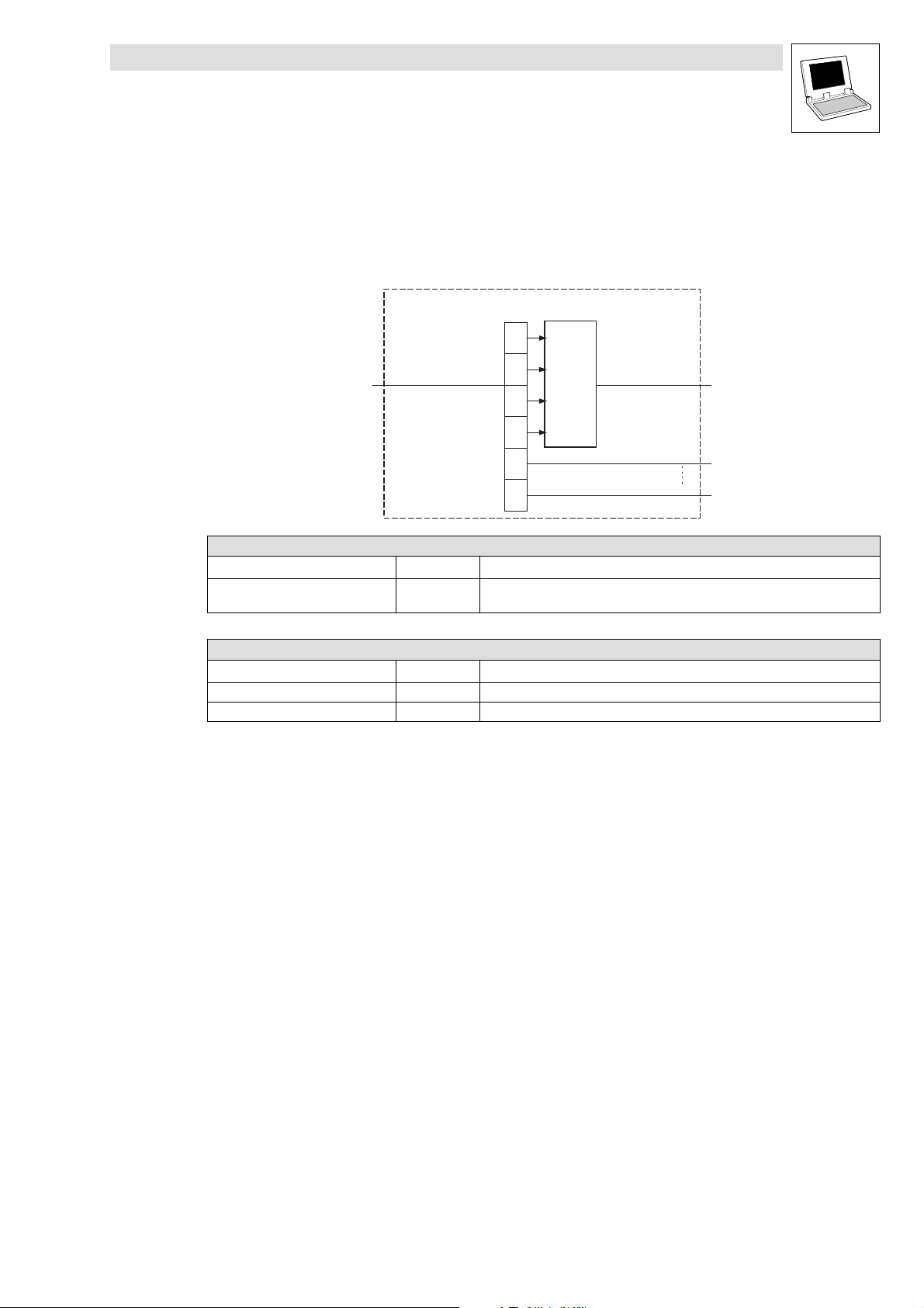
Function library LenzeIOSystem.lib
Function blocks
5.7 L_IOCounterDIModuleDataFromIO − Counter function
5.7 L_IOCounterDIModuleDataFromIO − Counter function
Function block L_IOCounterDIModuleDataFromIO supplies the counter module’s counting
information.
The 32−bit value of the counter is supplied at output dwCounter.
L_IOCounterDIModuleDataFromIO
DO
Byte
0
DO
Byte
1
abyPDO_DataFromIO
DO
Byte
DO
Byte
DO
Byte
DO
Byte
Converter
byte to dw
2
3
4
5
dwCounter
bBit0
bBit15
ð Inputs (Variable type: VAR_INPUT)
Variable name Data type Information/possible settings
abyPDO_DataFromIO Byte array Interface with outputs of function blocks L_IOPDO15 or L_IOPDO610 for the
transfer of count values from the counter module.
Outputs ð (Variable type: VAR_OUTPUT)
Identifier Data type Value/meaning
dwCounter Double word Output count value
bBit0 − bBit15 Bool Output status of digital inputs 0...15
L
LenzeIOSystem.lib EN 1.7
5−15
Page 62

Function library LenzeIOSystem.lib
Function blocks
5.8 L_IOSSIDataToIO − Counter function
5.8 L_IOSSIDataToIO − Counter function
Depending on a comparison value, the two outputs of the module can be set via function block
L_IOSSIDataToIO.
To the outputs, different comparison functions or comparison values can be assigned, which must
be transferred to the SSI module in succession.
bControl_SetOut_0
bControl_SetOut_1
bControl_Condition
dwSet_Compare
Converter
dw to byte
ð Inputs (Variable type: VAR_INPUT)
Variable name Data type Information/possible settings
bControl_Set_0 Bool Output 0
Monitor comparison value
bControl_Set_1 Bool Output 1
Monitor comparison value
bControl_Condition Bool Set condition of outputs
dwSet_Compare Double word Enter comparison value
DI
Byte
0
DI
Byte
1
DI
Byte
2
DI
Byte
3
0 Off
1 On
0 Off
1 On
0 Actual value > comparison value
1 Actual value < comparison value
L_IOSSIDataToIO
abyPDO_DataToIO
Outputs ð (Variable type: VAR_OUTPUT)
Identifier Data type Value/meaning
abyPDO_DataToIO Byte array Interface with the inputs of function blocks L_IOPDO15 or L_IOPDO610 for the
transfer of information from the counter module.
5−16
LenzeIOSystem.lib EN 1.7
L
Page 63

Function library LenzeIOSystem.lib
Function blocks
5.9 L_IOSSIDataFromIO − Counter function
5.9 L_IOSSIDataFromIO − Counter function
Function block L_IOSSIDataFromIO supplies the count value of the SSI module at output
dwSSI_Value.
· Output bStatusIO_0 Þ Status of I/O channel 0
· Output bStatusIO_1 Þ Status of I/O channel 1
The outputs are configured via function block L_IOSSIDataToIO.
L_IOSSIDataFromIO
DO
Byte
0
DO
Byte
1
abyPDO_DataFromIO
ð Inputs (Variable type: VAR_INPUT)
Variable name Data type Information/possible settings
abyPDO_DataToIO Byte array Interface with outputs of function blocks L_IOPDO15 or L_IOPDO610 for the transfer
Outputs ð (Variable type: VAR_OUTPUT)
Identifier Data type Value/meaning
bState_I/O_0 Bool Status of I/O channel 0
bState_I/O_1 Bool Status of I/O channel 1
dwSSI_Value Double word Count value of SSI module
DO
Converter
Byte
byte to dw
2
DO
Byte
3
of count values from the SSI module.
bState_I/O_0
bState_I/O_1
dwSSI_Value
L
LenzeIOSystem.lib EN 1.7
5−17
Page 64

Function library LenzeIOSystem.lib
Function blocks
5.10 L_IOConvByteToByteArray − Conversion function
5.10 L_IOConvByteToByteArray − Conversion function
Function block L_IOConvByteToByteArray converts 8 bytes of output data into an 8−field byte
array.
Due to this, the output data width is identical to exactly one transmit object PDO_DataToIO to the I/O
system.
L_IOConvByteToByteArray
byByte0_DataToIO abyPDO_DataToIO
byByte7_DataToIO
ð Inputs (Variable type: VAR_INPUT)
Variable name Data type Information/possible settings
byByte0_DataToIO
...
byByte7_DataToIO
Outputs ð (Variable type: VAR_OUTPUT)
Identifier Data type Value/meaning
abyPDO_DataToIO Byte array 8−byte array:
Byte 8 bytes digital output data to the I/O system
Maps one transmit object PDO_DataToIO
5−18
LenzeIOSystem.lib EN 1.7
L
Page 65

Function library LenzeIOSystem.lib
Function blocks
5.11 L_IOConvByteArrayToByte − Conversion function
5.11 L_IOConvByteArrayToByte − Conversion function
Function block L_IOConvByteArrayToByte converts 8 bytes of a receive object into 8 bytes of input
data.
Due to that, the input data width is matched to one receive object PDO_DataFromIO from the I/O
system.
L_IOConvByteArrayToByte
byByte0_DataFromIOabyPDO_DataFromIO
byByte7_DataFromIO
ð Inputs (Variable type: VAR_INPUT)
Variable name Data type Information/possible settings
abyPDO_DataFromIO Byte array 8−byte array:
Outputs ð (Variable type: VAR_OUTPUT)
Identifier Data type Value/meaning
byByte0_DataFromIO
...
byByte7_DataFromIO
Byte Receive object:
Maps one receive object PDO_DataFromIO
8 x 1 bytes of digital/analog input data from the I/O system
L
LenzeIOSystem.lib EN 1.7
5−19
Page 66

Function library LenzeIOSystem.lib
Function blocks
5.12 L_IODInModule − Bit conversion
5.12 L_IODInModule − Bit conversion
Function block L_IODInModule corresponds to a digital input module (EPM−T210) and converts one
data byte into the individual bits 0 − 7.
L_IODInModule
bBit0
byPDO_DataFromIO
Byte (8 bits)
ð Inputs (Variable type: VAR_INPUT)
Variable name Data type Information/possible settings
byPDO_DataFromIO Byte Digital inputs:
Outputs ð (Variable type: VAR_OUTPUT)
Identifier Data type Value/meaning
bBit0
...
bBit7
Bool Digital input information, bit 0.
1 byte data = 1 DI module
Digital input information, bit 7.
bBit1
bBit2
bBit3
bBit4
bBit6
bBit7
bBit8
...
5−20
LenzeIOSystem.lib EN 1.7
L
Page 67

Function library LenzeIOSystem.lib
Function blocks
5.13 L_IODOutModule − Bit conversion
5.13 L_IODOutModule − Bit conversion
Function block L_IODOutModule corresponds to a digital output module (EPM−T22X) and converts
the individual bits 0 − 7 into one data byte.
bBit0
L_IODOutModule
bBit1
bBit2
bBit3
bBit4
bBit5
bBit6
bBit7
ð Inputs (Variable type: VAR_INPUT)
Variable name Data type Information/possible settings
bBit0
...
bBit7
Outputs ð (Variable type: VAR_OUTPUT)
Identifier Data type Value/meaning
byPDO_DataFromIO Byte Digital outputs:
Bool Digital output information, bit 0
Digital output information, bit 7
1 byte data = 1 DO module
byPDO_DataToIO
Byte (8 bits)
...
L
LenzeIOSystem.lib EN 1.7
5−21
Page 68

Function library LenzeIOSystem.lib
Function blocks
5.14 L_IOAInModule − Signal conversion
5.14 L_IOAInModule − Signal conversion
The L_IOAInModule function block corresponds to an analog input module (EPM−T310 / T311 /
T312) and divides the data sent by the I/O system into the channel information 1 − 4.
The input data are represented in the integer format.
L_IOAInModule
nCH1
nCH2
^ 6−1
nCH3
nCH4
abyPDO_DataFromIO
ð Inputs (Variable type: VAR_INPUT)
Variable name Data type Information/possible settings
abyPDO_DataFromIO Byte array Analog input information of channels 1 − 4
Outputs ð (Variable type: VAR_OUTPUT)
Identifiers Data type Value/meaning
nCH1
...
nCH4
Integer Analog inputs:
4 x 2 bytes data = 1 AI module
Default ±10V function code 2B
h
5−22
LenzeIOSystem.lib EN 1.7
L
Page 69

Function library LenzeIOSystem.lib
Function blocks
5.15 L_IOAOutModule − Signal conversion
5.15 L_IOAOutModule − Signal conversion
The L_IOAOutModule function block corresponds to an analog output module (EPM−T320 / T321 /
T322) and bundles the information of channels 1 − 4 into a transmission object, which is sent to the
I/O system.
The output data are represented in the integer format.
nCH1
L_IOAOutModule
nCH2
nCH3
nCH4
ð Inputs (Variable type: VAR_INPUT)
Variable name Data type Information/possible settings
nCH1
...
nCH4
Outputs ð (Variable type: VAR_OUTPUT)
Identifiers Data type Value/meaning
abyPDO_DataFromIO Byte array Analog output information of channels 1 − 4
Byte Analog outputs:
4 x 2 bytes data = 1 AO module
abyPDO_DataToIO
Default ±10 = function code 01
^ 6−4
h
L
LenzeIOSystem.lib EN 1.7
5−23
Page 70

Function library LenzeIOSystem.lib
Function blocks
5−24
LenzeIOSystem.lib EN 1.7
L
Page 71

Function library LenzeIOSystem.lib
Appendix
6.1 Signal functions for analog inputs EPM−T310
6 Appendix
6.1 Signal functions for analog inputs EPM−T310
Parameter
bytes 2/3/4/5
00
h
01
h
02
h
03
h
04
h
05
h
05
h
07
h
08
h
09
h
0A
h
0B
h
0C
h
0D
h
0E
h
0F
h
10
h
11
h
12
h
13
h
14
h
15
h
18
h
19
h
1A
h
1B
h
1C
h
1D
h
27
h
29
h
2A
h
3B
h
Signal function Signal range Format Tolerance
Parameter data in module not overwritten
Temperature measuring
with two−wire connection
(complement on two)
Resistance measuring with
two−wire connection
Temperature measuring
with four−wire connection
(complement on two)
with PT100 −200.0 {0.1 °C} +850.0
A
with PT1000 −200.0 {0.1 °C} +500.0 ±1 °C
with NI100 −50.0 {0.1 °C} +250.0 ±1 °C
with NI1000 −50.0 {0.1 °C} +250.0 ±1 °C
at 60 W 0
0
at 600 W 0
0
at 3000 W 0
0
at 6000 W 0
0
{0.01 W}
{1 dec}
{0.01 W}
{1 dec}
{0.01 W}
{1 dec}
{0.01 W}
{1 dec}
+60.00
32767
+600.00
32767
+3000.00
32767
+6000.00
32767
with PT100 −200.0 {0.1 °C} +850.0
A
A
with PT1000 −200.0 {0.1 °C} +500.0 ±0.5 °C
with NI100 −50.0 {0.1 °C} +250.0 ±0.5 °C
2)
±1 °C
2)
2)
2)
±0.2 % of limit value
±0.2 % of limit value
±0.2 % of limit value
±0.2 % of limit value
±0.5 °C
with NI1000 −50.0 {0.1 °C} +250.0 ±0.5 °C
Resistance measuring with
two−wire connection
at 60 W 0 {0.01 W} +60.00
at 600 W 0 {0.01 W} +600.00 ±0.05 % of limit value
A
±0.1 % of limit value
at 3000 W 0 {0.01 W} +3000.00 ±0.05 % of limit value
Temperature measuring
with thermocouple and
external compensation
(complement on two)
with type J −210.0 {0.1 °C} +850.0
with type K −270.0 {0.1 °C} +1200.0 ±1.5 °C
3)
with type N −200.0 {0.1 °C} +1300.0 ±1.5 °C
with type R −50.0 {0.1 °C} +1760.0 ±4 °C
A
±1 °C
with type T −270.0 {0.1 °C} +400.0 ±1.5 °C
with type S −50.0 {0.1 °C} +1760.0 ±5 °C
Temperature measuring
with thermocouple and
internal compensation
(complement on two)
with type J −210.0 {0.1 °C} +850.0
with type K −270.0 {0.1 °C} +1200.0 ±2 °C
4)
with type N −200.0 {0.1 °C} +1300.0 ±2 °C
with type R −50.0 {0.1 °C} +1760.0 ±5 °C
A
±1.5 °C
with type T −270.0 {0.1 °C} +400.0 ±2 °C
with type S −50.0 {0.1 °C} +1760.0 ±5 °C
Voltage measuring
(complement on two)
0 ... 50 mV
0
0
{0.01 mV}
{1 dec}
+50.00
27648
A ±0.1 % of limit value
Lower range limit: –
Upper range limit: +59.25 mV
32767 dec
Voltage measuring
(complement on two)
±4 V
−4.00
−27648
{0.01 V}
{1 dec}
+4.00 V
27648 dec
A ±0.05 % of limit value
Lower range limit: −4.74 V
−32767 dec
Upper range limit: +4.74 V
32767 dec
Voltage measuring
(complement on two)
±400 mV
−400
−27648
{1 mV}
{1 dec}
+400
27648
A ±0.1 % of limit value
Lower range limit: −474 mV
−32767 dec
Upper range limit: +474 mV
32767 dec
Voltage measuring
(complement on two)
±10 V −10.00
−16384
{0.01 V}
{1 dec}
+10.00
16384
B ±0.2 % of limit value
1)
2)
2)
2)
2)
L
LenzeIOSystem.lib EN 1.7
6−1
Page 72

Function library LenzeIOSystem.lib
Appendix
6.1 Signal functions for analog inputs EPM−T310
Parameter
bytes 2/3/4/5
2C
h
2D
h
2E
h
32
h
33
h
35
h
36
h
37
h
38
h
Current measuring
(complement on two)
Current measuring
(complement on two)
Current measuring 4 ... 20 mA
Resistance measuring with
four−wire connection
±20 mA
4 ... 20 mA
at 6000 W 0
at 6000 W 0
at 60 W 0
at 600 W 0
at 3000 W 0
at 6000 W 0
Lower range limit: −11.85 V
Upper range limit: +11.85 V
−20.00
−27648
Lower range limit: −23.70 mA
Upper range limit: +23.70 mA
4.00
0
Lower range limit: 1.185 mA
Upper range limit: +22.96 mA
4.00
0
Lower range limit: 1.185 mA
Upper range limit: +22.96 mA
0
0
0
0
0
0
{0.01 mA}
{1 dec}
{0.01 mA}
{1 dec}
{0.01 mA}
{1 dec}
{0.01 W}
{1 dec}
{0.01 W}
{1 dec}
{0.01 W} +6000.00
{0.01 W}
{1 dec}
{0.01 W}
{1 dec}
{0.01 W}
{1 dec}
−20480 dec
20480 dec
+20.00
27648
−32767 dec
+32767 dec
20.00
27648
−4864 dec
+32767 dec
20.00
16384
−2882 dec
+20480 dec
+6000.00
32767 dec
+6000.00
6000 dec
6000 dec
+600.00
6000 dec
+3000.00
30000 dec
+6000.00
6000 dec
FormatSignal rangeSignal function
Tolerance
A ±0.05 % of limit value
A ±0.05 % of limit value
B ±0.2 % of limit value
A
±0.05 % of limit value
±0.05 % of limit value
±0.2 % of limit value
±0.1 % of limit value
±0.1 % of limit value
±0.1 % of limit value
1)
2)
2)
2)
2)
6−2
LenzeIOSystem.lib EN 1.7
L
Page 73

Function library LenzeIOSystem.lib
Appendix
6.1 Signal functions for analog inputs EPM−T310
Parameter
bytes 2/3/4/5
3A
h
3B
h
3D5
h
3E
h
3F
h
57
h
58
h
59
h
5A
h
5C
h
5D
h
FF
h
1)
The tolerance values were established at 25 °C ambient temperature and 15 conversions/s. No sensor inaccuracies were taken into
consideration.
2)
Contact and line resistances were not taken into consideration.
3)
Reference junction compensation to be effected externally.
4)
Reference junction compensation is effected internally, taking into consideration the terminal temperature. Connect the thermocouple
conductors directly to the terminal using a thermocouple extension cable if necessary.
Current measuring
(complement on two)
Voltage measuring
(complement on two)
Resistance measuring with
four−wire connection
Voltage measuring 0 ... 50 mV
Voltage measuring
(complement on two)
Voltage measuring
(complement on two)
Voltage measuring
(complement on two)
Current measuring
(complement on two)
Current measuring
(complement on two)
Analog input deactivated
±20 mA −20.00
±10 V −10.00
at 60 W 0
at 600 W 0
at 3000 W 0
±10 V
±4 V
±400 mV
±20 mA
4 ... 20 mA
−16384
Lower range limit: −23.70 mA
Upper range limit: +23.70 mA
−16384
Lower range limit: −12.5 V
Upper range limit: +12.5 V
0
0
0
0
0
Upper range limit: +59.25 V
−10.00
−10000
Lower range limit: −11.85 V
Upper range limit: +11.85 V
−4.00
−40000
Lower range limit: −4.74 V
Upper range limit: +4.74 V
−400
−40000
Lower range limit: −474 mV
Upper range limit: +474 mV
−20.00
−20000
Lower range limit: −23.70 mA
Upper range limit: +23.70 mA
4.00
0
Lower range limit: 1.185 mA
Upper range limit: +22.96 mA
{0.01 mA}
{1 dec}
{0.01 V}
{1 dec}
{0.01 W}
{1 dec}
{0.01 W}
{1 dec}
{0.01 W}
{1 dec}
{0.01 mV}
{1 dec}
{0.01 V}
{1 dec}
{0.01 V}
{1 dec}
{1 mV}
{1 dec}
{0.01 mA}
{1 dec}
{0.01 mA}
{1 dec}
−19456 dec
+19456 dec
−20480 dec
20480 dec
6000 dec
+600.00
6000 dec
+3000.00
30000 dec
5925 dec
−11850 dec
11850 dec
−47400 dec
47400 dec
−47400 dec
47400 dec
−23700 dec
+23700 dec
−2815 dec
+22960 dec
FormatSignal rangeSignal function
+20.00
16384
+10.00
16384
+60.00
+50.00
5000
+10.00
10000
+4.00 V
40000
+400
40000
+20.00
20000
20.00
16000
Tolerance
A ±0.05 % of limit value
B ±0.2 % of limit value
A
±0.1 % of limit value
±0.05 % of limit value
±0.05 % of limit value
A ±0.1 % of limit value
A ±0.05 % of limit value
A ±0.05 % of limit value
A ±0.1 % of limit value
A ±0.05 % of limit value
A ±0.05 % of limit value
1)
L
LenzeIOSystem.lib EN 1.7
6−3
Page 74

Function library LenzeIOSystem.lib
Appendix
6.2 Signal functions for analog outputs EPM−T320
6.2 Signal functions for analog outputs EPM−T320
Parameter
bytes 2/3/4/5
00
h
01
h
02
h
05
h
09
h
0A
h
0D
h
03
h
04
h
06
h
Signal function Signal range Signal
No signal emitted at output
Voltage signal output ±10 V
Voltage signal output +1 ... +5 V
Voltage signal output 0 ... +10 V
Voltage signal output
(complement on two)
Voltage signal output
(complement on two)
Voltage signal output
(complement on two)
Current signal output ±20 mA
Current signal output 4 ... 20 mA
Current signal output 0 ... 20 mA
±10 V
+1 ... +5 V
0 ... +10 V
−10.00
−16384
Lower range limit: −11.85 V
Upper range limit: +11.85 V
1.0
0
Lower range limit: 0 V
Upper range limit: +6.0 V
0
0
Lower range limit: –
Upper range limit: +12.5 V
−10.00
−27648
Lower range limit: −11.85 V
Upper range limit: +11.84 V
1.00
0
Lower range limit: 0 V
Upper range limit: +5.75 V
0
0
Lower range limit: –
Upper range limit: +11.5 V
−20.00
−16384
Lower range limit: −23.70 mA
Upper range limit: +23.70 mA
4.00
0
Lower range limit: 0 mA
Upper range limit: +23.70 mA
0
0
Lower range limit: —
Upper range limit: +23.70 mA
{0.01 V}
{1 dec}
{0.1 V}
{1 dec}
{0.1 V}
{1 dec}
{0.01 V}
{1 dec}
{0.01 V}
{1 dec}
{0.1 V}
{1 dec}
{0.01 mA}
{1 dec}
{0.01 mA}
{1 dec}
{0.01 mA}
{1 dec}
−20480 dec
20480 dec
20480 dec
20480 dec
20480 dec
+10.00 V
27648 dec
−32767 dec
32767 dec
−6912 dec
32767 dec
32767 dec
−20480 dec
+20480 dec
−4096 dec
+20480 dec
+20480 dec
resolution
+10.00
16384
+5.0
16384
+10.0
16384
+5.00
27648
+10.0
27648
+20.00
16384
20.00
16384
+20.00
16384
Tolerance
B ±0.2 %
B ±0.05 %
B ±0.2 %
A ±0.05 %
A ±0.05 %
A ±0.2 %
B ±0.2 %
B ±0.2 %
B ±0.2 %
1)
6−4
LenzeIOSystem.lib EN 1.7
L
Page 75

Function library LenzeIOSystem.lib
Appendix
6.2 Signal functions for analog outputs EPM−T320
Parameter
bytes 2/3/4/5
0B
h
0C
h
0E
h
1)
The tolerance values were established at 25 °C ambient temperature and 15 conversions/s and are related to the limit value.
Current signal output
(complement on two)
Current signal output
(complement on two)
Current signal output
(complement on two)
±20 mA
4 ... 20 mA
0 ... 20 mA
Signal rangeSignal function
−20.00
−27648
Lower range limit: −23.70 mA
Upper range limit: +23.70 mA
4.00
0
Lower range limit: 0 mA
Upper range limit: +22.96 mA
0
0
Lower range limit: –
Upper range limit: +22.96 mA
{0.01 mA}
{1 dec}
−32767 dec
+32767 dec
{0.01 mA}
{1 dec}
−5530 dec
+32767 dec
{0.01 mA}
{1 dec}
+32767 dec
+20.00
27648
20.00
27648
20.00
27648
Signal
resolution
A ±0.05 %
A ±0.05 %
A ±0.2 %
Tolerance
1)
L
LenzeIOSystem.lib EN 1.7
6−5
Page 76

Function library LenzeIOSystem.lib
Appendix
6.3 Signal functions for analog inputs and outputs EPM−T330
6.3 Signal functions for analog inputs and outputs EPM−T330
Input range (channels 0, 1)
Parameter
bytes 2/3/4/5
00
h
3B
h
75
h
28
h
7A
h
7D
h
3A
h
76
h
2C
h
2D
h
Signal function Signal range Format Tolerance
Parameter data in module not overwritten
Voltage measuring
(complement on two)
±10 V
−10.00
−16384
{0.01 V}
{1 dec}
+10.00
+16384
Lower range limit: −12.50 V
−20480
dec
±0.2 % of limit value
B
Upper range limit: +12.50 V
+20480
Voltage measuring 0...10 V
0.00
0
{0.01 V}
{1 dec}
Lower range limit: −
dec
+10.00
+16384
±0.4 % of limit value
B
Upper range limit: +12.50 V
+20480
Voltage measuring
(complement on two)
±10 V
−10.00
−27648
{0.01 V}
{1 dec}
Lower range limit: −11.76 V
+10.00
+27648
−32512
dec
dec
±0.2 % of limit value
A
Upper range limit: +11.76 V
+32511
Voltage measuring 1 ... 5V
+1.00
0
{0.01 V}
{1 dec}
Lower range limit: 0.00 V
+5.00
+27648
−6912
dec
dec
±0.6 % of limit value
A
Upper range limit: +5.704 V
+32511
Voltage measuring 0...10 V
0.00
0
{0.01 V}
{1 dec}
Lower range limit: −
dec
+10.00
+27648
±0.4 % of limit value
A
Upper range limit: +11.76 V
+32511
Current measuring
(complement on two)
±20 mA
−20.00
−16384
{0.01 mA}
{1 dec}
Lower range limit: −25.00 mA
+20.00
+16384
−20480
dec
dec
±0.3 % of limit value
B
Upper range limit: +25.00 mA
+20480
Current measuring 0 ... 20 mA
0.00
0
{0.01 mA}
{1 dec}
Lower range limit: −
dec
+20.00
+16384
±0.6 % of limit value
B
Upper range limit: +25.00 mA
+20480
Current measuring
(complement on two)
±20 mA
−20.00
−27648
{0.01 mA}
{1 dec}
Lower range limit: −23.51 mA
+20.00
+27648
−32512
dec
dec
±0.3 % of limit value
A
Upper range limit: +23.51 mA
+32511
Current measuring
(complement on two)
4 ... 20 mA
+4.00
0
{0.01 mA}
{1 dec}
Lower range limit: +1.18 mA
+20.00
+27648
−4864
dec
dec
±0.8 % of limit value
A
Upper range limit: +22.81 mA
+32511
dec
1)
6−6
LenzeIOSystem.lib EN 1.7
L
Page 77

Function library LenzeIOSystem.lib
Appendix
6.3 Signal functions for analog inputs and outputs EPM−T330
Parameter
bytes 2/3/4/5
7E
h
FF
h
Current measuring 0 ... 20 mA
Analog input deactivated
1)
The tolerance values were established at 25 °C ambient temperature and 15 conversions/s. No sensor
inaccuracies were taken into consideration.
Output range (channels 2, 3)
Parameter
bytes 2/3/4/5
00
h
01
h
02
h
05
h
09
h
0A
h
0D
h
03
h
Signal function Signal range Format Tolerance
Parameter data in module not overwritten
Voltage signal output ±10 V
Voltage signal output 1 ... 5V
Voltage signal output 0...10 V
Voltage signal output
(complement on two)
Voltage signal output
(complement on two)
Voltage signal output 0...10 V
Current signal output ±20 mA
±10 V
1 ... 5V
0.00
0
{0.01 mA}
{1 dec}
+20.00
+27648
Lower range limit: −
Upper range limit: +23.52 mA
+32511
dec
−10.00
−16384
{0.01 V}
{1 dec}
+10.00
+16384
Lower range limit: −12.50 V
−20480
dec
Upper range limit: +12.50 V
+20480
dec
+1.00
0
{0.01 V}
{1 dec}
+5.00
+16384
Lower range limit: 0.00 V
−4096
dec
Upper range limit: +6.00 V
+20480
0.00
0
{0.01 V}
{1 dec}
dec
+10.00
+16384
Lower range limit: −
Upper range limit: +12.50 V
+20480
dec
−10.00
−27648
{0.01 V}
{1 dec}
+10.00
+27648
Lower range limit: −11.76 V
−32512
dec
Upper range limit: +11.76 V
+32511
dec
+1.00
0
{0.01 V}
{1 dec}
+5.00
+27648
Lower range limit: 0.00 V
−6912
dec
Upper range limit: +5.704 V
+32511
dec
0.00
0
{0.01 V}
{1 dec}
+10.00
+27648
Lower range limit: −
Upper range limit: +11.76 V
+32511
dec
−20.00
−16384
{0.01 mA}
{1 dec}
+20.00
+16384
Lower range limit: −25.00 mA
−20480
dec
Upper range limit: +25.00 mA
+20480
dec
FormatSignal rangeSignal function
Tolerance
1)
±0.6 % of limit value
A
1)
±0.2 % of limit value
B
±0.6 % of limit value
B
±0.4 % of limit value
B
±0.2 % of limit value
A
±0.6 % of limit value
A
±0.4 % of limit value
A
±0.3 % of limit value
B
L
LenzeIOSystem.lib EN 1.7
6−7
Page 78

Function library LenzeIOSystem.lib
Appendix
6.3 Signal functions for analog inputs and outputs EPM−T330
Parameter
bytes 2/3/4/5
04
h
06
h
0B
h
0C
h
0E
h
FF
h
Current signal output 4 ... 20 mA
Current signal output 0 ... 20 mA
Current signal output
(complement on two)
Current signal output
(complement on two)
Current signal output 0 ... 20 mA
Analog output deactivated
±20 mA
4 ... 20 mA
+4.00
0
Lower range limit: +0.00 mA
Upper range limit: +24.00 mA
0.00
0
Lower range limit: −
Upper range limit: +25.00 mA
−20.00
−27648
Lower range limit: −23.52 mA
Upper range limit: +23.52 mA
+4.00
0
Lower range limit: +0.00 mA
Upper range limit: +22.81 mA
0.00
0
Lower range limit: −
Upper range limit: +23.52 mA
{0.01 mA}
{1 dec}
{0.01 mA}
{1 dec}
{0.01 mA}
{1 dec}
{0.01 mA}
{1 dec}
{0.01 mA}
{1 dec}
+20.00
+16384
−4096
+20480
+20.00
+16384
+20480
+20.00
+27648
−32512
+32511
+20.00
+27648
−6912
+32511
+20.00
+27648
+32511
dec
dec
dec
dec
dec
dec
dec
dec
FormatSignal rangeSignal function
Tolerance
±0.8 % of limit value
B
±0.6 % of limit value
B
±0.3 % of limit value
A
±0.8 % of limit value
A
±0.6 % of limit value
A
1)
1)
The tolerance values were established at 25 °C ambient temperature and 15 conversions/s. No sensor
inaccuracies were taken into consideration.
6−8
LenzeIOSystem.lib EN 1.7
L
Page 79

Function library LenzeIOSystem.lib
Appendix
6.4 Measured value scaling
6.4 Measured value scaling
Signal
range
±10 V
0 ... 10 V
1 ... 5V
±4 V
±400 mV
4 ... 20 mA
±20 mA
Signal
[U] / [I]
−10 V −27648 9400
+10 V +27648 6C00 +16384 4000
+10 V +16384 4000 +16384 4000
−400 mV −27648 9400
+400 mV +27648 6C00
+4 mA 0 0000
+12 mA +13824 3600 +8192 2000
+20 mA +27648 6C00 +16384 4000
−20 mA −27648 9400
−10 mA −13824 CA00 −8192 E000
0 mA 0 0000 0 0000
+10 mA +13824 3600 +8192 2000
+20 mA +27648 6C00 +16384 4000
Decimal value
[dec]
−5 V −13824 CA00 −8192 E000
0 V 0 0000 0 0000
+5 V +13824 3600 +8192 2000
0 V 0 0000
+5 V +8192 2000 +8192 2000
+1 V
+3 V +8192 2000
+5 V +16384 4000
−4 V −27648 9400
0 V 0 0000
+4 V +27648 6C00
0 V 0 0000
15−bit signal resolution 12−bit signal resolution
Hexadecimal value
[hex]
Formulae for calculation Decimal value
27648
16384
27648
400
27648
16
27648
27648
U
10
10
U
10
10
U
4
4
U
400
I * 4
16
)1
I
20
20
dec + 27648 @
U +dec@
dec + 16384 @
U +dec@
dec + 27648 @
U +dec@
dec + 27648 @
U +dec@
dec + 27648 @
U +dec@
dec + 27648 @
U +dec@
[dec]
−16384 C000
0 0000
0 0000
0 0000
−16384 C000
Hexadecimal value
[hex]
Formulae for calculation
16348
16384
4
16384
16
16384
16384
U
10
10
U
10
10
U * 1
4
)1
I * 4
16
)1
I
20
20
dec + 16348 @
U +dec@
dec + 16384 @
U +dec@
dec + 27648 @
U +dec@
dec + 16384 @
U +dec@
dec + 16384 @
U +dec@
L
LenzeIOSystem.lib EN 1.7
6−9
Page 80

Function library LenzeIOSystem.lib
Appendix
6.5 Selecting the counter modes EPM−T410
6.5 Selecting the counter modes EPM−T410
Mode
[hex] [dec]
00
h
01
h
03
h
05
h
08
h
09
h
0A
h
0B
h
0C
h
0D
h
0E
h
0F
h
10
h
11
h
12
h
13
h
06
h
14
h
15
h
16
h
17
h
18
h
19
h
1A
h
1B
h
1C
h
Function IN1 IN2 IN3 IN4 IN5 IN6 OUT0 OUT1 Auto
Reload
Compare
Load
2 counters 0 1
0 32 bit counter RES CLK DIR RES CLK DIR · · – –
1 Encoder 1 edge RES A B RES A B · · – –
3 Encoder 2 edges RES A B RES A B · · – –
5 Encoder 4 edges RES A B RES A B · · – –
4 counters 0.1 0.2 1.1 1.2
8 2 × 16 bit counters
– CLK CLK – CLK CLK – – – –
(counting direction upwards/upwards)
9 2 × 16 bit counters
– CLK CLK – CLK CLK – – – –
(counting direction downwards/upwards)
10 2 × 16 bit counters
– CLK CLK – CLK CLK – – – –
(counting direction downwards/upwards)
11 2 × 16 bit counters
– CLK CLK – CLK CLK – – – –
(counting direction downwards/upwards)
2 counters 0 1
12 2 × 32 bit counters (counting direction
RES CLK GATE RES CLK GATE · · – ü
upwards)
13 2 × 32 bit counters (counting direction
RES CLK GATE RES CLK GATE · · – ü
downwards)
14 2 × 32 bit counters (counting direction
RES CLK GATE RES CLK GATE · · ü ü
upwards)
15 2 × 32 bit counters (counting direction
RES CLK GATE RES CLK GATE · · ü ü
downwards)
1 counter 0/1
16 Frequency measuring RES CLK START STOP – – · · – ü
17 Measuring the period RES CLK START STOP – – · · – ü
18 Frequency measuring
RES CLK START STOP – – · · – ü
(output counter runs/stops)
19 Measuring the period
RES CLK START STOP – – · · – ü
(output counter runs/stops)
2 counters 0 1
6 Measuring the pulse width
(f
50 kHz, counting direction selectable)
ref
20 Measuring the pulse width
(f
programmable, counting direction
ref
selectable)
21 Measuring the pulse width
(f
programmable, counting direction
ref
upwards)
22 Measuring the pulse width
(f
programmable, counting direction
ref
downwards)
RES PULSE DIR RES PULSE DIR – – – –
RES PULSE DIR RES PULSE DIR – – – –
RES PULSE DIR RES PULSE GATE – – – –
RES PULSE DIR RES PULSE GATE – – – –
2 counters 0 1
23 2 × 32 bit counters
RES CLK GATE RES CLK GATE – – – ü
(counting direction upwards, set function)
24 2 × 32 bit counters
RES CLK GATE RES CLK GATE – – – ü
(counting direction upwards, set function)
25 2 × 32 bit counters
RES CLK GATE RES CLK GATE – – – ü
(counting direction upwards, reset function)
26 2 × 32 bit counters
RES CLK GATE RES CLK GATE – – – ü
(counting direction upwards, reset function)
2 counters 0 1
27 32 bit counter G/RESû CLK DIR G/RESû CLK DIR · · – –
28 Encoder 1 edge G/RESû A B G/RESû A B · · – –
6−10
LenzeIOSystem.lib EN 1.7
L
Page 81

Function library LenzeIOSystem.lib
Appendix
6.5 Selecting the counter modes EPM−T410
Mode Compare
[hex]
[dec]
1D
1E
1F
20
21
22
29 Encoder 2 edges G/RESû A B G/RESû A B · · – –
h
30 Encoder 4 edges G/RESû A B G/RESû A B · · – –
h
2 counters 0 1
31 2 × 32 bit counters (counting direction
h
h
h
h
downwards)
32 2 × 32 bit counters (counting direction
downwards)
33 2 × 32 bit counters (counting direction
downwards)
34 2 × 32 bit counters (counting direction
downwards)
RESû CLK GATE RESû CLK GATE · · – ü
RESû CLK GATE RESû CLK GATE · · – ü
RESû CLK GATE RESû CLK GATE · · ü ü
RESû CLK GATE RESû CLK GATE · · ü ü
· Digital output may signal an event.
ü Function available.
– No function / function not available.
A Encoder signal A
Auto Reload Auto Reload causes the counter to accept a preset value as soon
as the counter reading matches the Compare register content.
B Encoder signal B
Compare Load You may use Compare Load to specify a counter limit value to
trigger an output or to restart the counters via Auto Reload when it
is reached.
CLK Clock signal of a linked encoder
HIGH: Starts or stops the counting
DIR Indicates counting direction depending on signal level.
LOW: Upcounter
HIGH: Downcounter
GATE Gate signal level−triggered
HIGH: Pulses are measured
G/RESû Gate signal level−triggered and reset signal edge−triggered
HIGH: Pulses are measured
LOW−HIGH edge: Resets one or both counter(s)
PULSE The pulse width of the supplied signal is measured with an internal
time base
RES Reset signal level−triggered
HIGH: Resets one or both counter(s)
RESû Reset signal edge−triggered
LOW−HIGH edge: Resets one or both counter(s)
START Start signal edge−triggered
STOP Stop signal edge−triggered
OUT1OUT0IN6IN5IN4IN3IN2IN1Function
OUT1OUT0IN6IN5IN4IN3IN2IN1Function
Auto
Auto
Reload
Reload
Compare
Load
Load
L
LenzeIOSystem.lib EN 1.7
6−11
Page 82

Function library LenzeIOSystem.lib
Appendix
6−12
LenzeIOSystem.lib EN 1.7
L
Page 83

7 Index
Function library LenzeIOSystem.lib
Index
A
Analog inputs and outputs EPM−T330, 6−6
Analog inputs EPM−T310, 6−1
Analog outputs EPM−T320, 6−4
B
Bit conversion, 5−20 , 5−21
C
C_wLenzeIOSystemVersion, 1−1
Conversion function, 5−18 , 5−19
Coordinate data, 5−2 , 5−5 , 5−8
Counter function, 4−14 , 4−16 , 5−11 , 5−13 , 5−14 ,
5−15 , 5−16 , 5−17
Counter modes, 6−10
I
Initialising, 3−5
Initialising the CAN driver, CAN driver, Initialising, 3−1
L
L_IOAInModule, 5−22
L_IOAOutModule, 5−23
L_IOConvByteArrayToByte, 5−19
L_IOConvByteToByteArray, 5−18
L_IOCounterDataFromIO, 5−13
L_IOCounterDataToIO, 5−11
L_IOCounterDIModuleDataFromIO, 5−15
L_IOCounterDIModuleDataToIO, 5−14
L_IOData15, 5−2
L_IOData610, 5−5
L_IODataCompactModule, 5−8
L_IODInModule, 5−20
L_IODOutModule, 5−21
L_IOParAlAOModule, 4−9
L_IOParAlnModule, 4−4
L_IOParAOutModule, 4−7
L_IOParComGuarding, 4−2
L_IOParCompactModule, 4−26
L_IOParCounterDIModule, 4−16
L_IOParCounterModule, 4−14
L_IOParPDO15, 4−18
L_IOParPDO610, 4−22
L_IOParSSIModule, 4−12
L_IOSSIDataFromIO, 5−17
L_IOSSIDataToO, 5−16
M
Minimum configuration, 2−2
Monitoring function, 4−2
P
Parameter data blocks, 2−1
Parameterisation function, 4−4 , 4−7 , 4−9 , 4−12 , 4−18 ,
4−22 , 4−26
Process data blocks, 2−1
S
Safety information, layout
more notes, 1−2
warning of material damage, 1−2
Scaling, 6−9
Signal conversion, 5−22 , 5−23
Signal functions, 6−1 , 6−4 , 6−6
T
Term definitions, 1−2
V
Version identifiers of the function library, 1−3
L
LenzeIOSystem.lib EN 1.7
7−1
 Loading...