

Page 1

L
Manual
Global Drive
PLC Developer Studio
Global Drive
Function library
LenzeDrive.lib
Page 2

The function library LenzeDrive.lib can be used for the following Lenze PLC devices:
Type as of hardware version as of software version
9300 Servo PLC EVS93XX−xI 2K 1.0
9300 Servo PLC EVS93XX−xT 2K 1.0
Drive PLC EPL10200 VA 1.0
ECSxA ECSxAxxx 1C 7.0
Important note:
The software is supplied to the user as described in this document. Any risks resulting from its quality or use remain the responsibility
of the user. The user must provide all safety measures protecting against possible maloperation.
We do not take any liability for direct or indirect damage, e.g. profit loss, order loss or any loss regarding business.
2006 Lenze Drive Systems GmbH
No part of this documentation may be copied or made available to third parties without the explicit written approval of Lenze Drive
Systems GmbH.
All information given in this documentation has been carefully selected and tested for compliance with the hardware and software
described. Nevertheless, discrepancies cannot be ruled out. We do not accept any responsibility or liability for any damage that may
occur. Required corrections will be included in updates of this documentation.
All product names mentioned in this documentation are trademarks of the corresponding owners.
Version 1.7 07/2006
Page 3

Function library LenzeDrive.lib
Contents
1 Preface and general information 1−1 . . . . . . . . . . . . . . . . . . . . . . . . . . . . . . . . . . . . . . . . . . .
1.1 About this Manual 1−1 . . . . . . . . . . . . . . . . . . . . . . . . . . . . . . . . . . . . . . . . . . . . . . . . . . . . . . . . . . . . . . . .
1.1.1 Conventions used in this Manual 1−1 . . . . . . . . . . . . . . . . . . . . . . . . . . . . . . . . . . . . . . . . . . . . . .
1.1.2 Description layout 1−2 . . . . . . . . . . . . . . . . . . . . . . . . . . . . . . . . . . . . . . . . . . . . . . . . . . . . . . . . .
1.1.3 Pictographs used in this Manual 1−2 . . . . . . . . . . . . . . . . . . . . . . . . . . . . . . . . . . . . . . . . . . . . . . .
1.1.4 Terminology used 1−2 . . . . . . . . . . . . . . . . . . . . . . . . . . . . . . . . . . . . . . . . . . . . . . . . . . . . . . . . .
1.2 Lenze software guidelines for variable names 1−3 . . . . . . . . . . . . . . . . . . . . . . . . . . . . . . . . . . . . . . . . . . . .
1.2.1 Hungarian Notation 1−3 . . . . . . . . . . . . . . . . . . . . . . . . . . . . . . . . . . . . . . . . . . . . . . . . . . . . . . . .
1.2.1.1 Recommendation for designating variable types 1−4 . . . . . . . . . . . . . . . . . . . . . . . . . .
1.2.1.2 Designation of the signal type in the variable name 1−5 . . . . . . . . . . . . . . . . . . . . . . .
1.2.1.3 Special handling of system variables 1−5 . . . . . . . . . . . . . . . . . . . . . . . . . . . . . . . . . .
1.3 Version identifiers of the function library 1−6 . . . . . . . . . . . . . . . . . . . . . . . . . . . . . . . . . . . . . . . . . . . . . . . .
2 Function blocks 2−1 . . . . . . . . . . . . . . . . . . . . . . . . . . . . . . . . . . . . . . . . . . . . . . . . . . . . . . . .
2.1 General signal processing 2−2 . . . . . . . . . . . . . . . . . . . . . . . . . . . . . . . . . . . . . . . . . . . . . . . . . . . . . . . . . . .
2.1.1 Programming fixed setpoints (L_FIXSET) 2−2 . . . . . . . . . . . . . . . . . . . . . . . . . . . . . . . . . . . . . . . . .
2.2 Analog signal processing 2−4 . . . . . . . . . . . . . . . . . . . . . . . . . . . . . . . . . . . . . . . . . . . . . . . . . . . . . . . . . . .
2.2.1 Absolute value generation (L_ABS) 2−4 . . . . . . . . . . . . . . . . . . . . . . . . . . . . . . . . . . . . . . . . . . . . .
2.2.2 Addition (L_ADD) 2−5 . . . . . . . . . . . . . . . . . . . . . . . . . . . . . . . . . . . . . . . . . . . . . . . . . . . . . . . . . .
2.2.3 Input gain and offset (L_AIN) 2−6 . . . . . . . . . . . . . . . . . . . . . . . . . . . . . . . . . . . . . . . . . . . . . . . . .
2.2.4 Inversion (L_ANEG) 2−8 . . . . . . . . . . . . . . . . . . . . . . . . . . . . . . . . . . . . . . . . . . . . . . . . . . . . . . . .
2.2.5 Output gain and offset (L_AOUT) 2−9 . . . . . . . . . . . . . . . . . . . . . . . . . . . . . . . . . . . . . . . . . . . . . . .
2.2.6 Arithmetic (L_ARIT) 2−11 . . . . . . . . . . . . . . . . . . . . . . . . . . . . . . . . . . . . . . . . . . . . . . . . . . . . . . . .
2.2.7 Changeover (L_ASW) 2−12 . . . . . . . . . . . . . . . . . . . . . . . . . . . . . . . . . . . . . . . . . . . . . . . . . . . . . . .
2.2.8 Comparison (L_CMP) 2−13 . . . . . . . . . . . . . . . . . . . . . . . . . . . . . . . . . . . . . . . . . . . . . . . . . . . . . . .
2.2.9 Curve function (L_CURVE) 2−17 . . . . . . . . . . . . . . . . . . . . . . . . . . . . . . . . . . . . . . . . . . . . . . . . . . .
2.2.10 Dead−band (L_DB) 2−20 . . . . . . . . . . . . . . . . . . . . . . . . . . . . . . . . . . . . . . . . . . . . . . . . . . . . . . . . .
2.2.11 Differentiation (L_DT1_) 2−21 . . . . . . . . . . . . . . . . . . . . . . . . . . . . . . . . . . . . . . . . . . . . . . . . . . . . .
2.2.12 Limiting (L_LIM) 2−22 . . . . . . . . . . . . . . . . . . . . . . . . . . . . . . . . . . . . . . . . . . . . . . . . . . . . . . . . . .
2.2.13 Delay (L_PT1_) 2−23 . . . . . . . . . . . . . . . . . . . . . . . . . . . . . . . . . . . . . . . . . . . . . . . . . . . . . . . . . . .
2.2.14 Ramp generator (L_RFG) 2−24 . . . . . . . . . . . . . . . . . . . . . . . . . . . . . . . . . . . . . . . . . . . . . . . . . . . .
2.2.15 Sample & Hold (L_SH) 2−26 . . . . . . . . . . . . . . . . . . . . . . . . . . . . . . . . . . . . . . . . . . . . . . . . . . . . . .
2.2.16 S−ramp generator (L_SRFG) 2−27 . . . . . . . . . . . . . . . . . . . . . . . . . . . . . . . . . . . . . . . . . . . . . . . . . .
2.3 Digital signal processing 2−29 . . . . . . . . . . . . . . . . . . . . . . . . . . . . . . . . . . . . . . . . . . . . . . . . . . . . . . . . . . . .
2.3.1 Logical AND (L_AND) 2−29 . . . . . . . . . . . . . . . . . . . . . . . . . . . . . . . . . . . . . . . . . . . . . . . . . . . . . . .
2.3.2 Delay (L_DIGDEL) 2−30 . . . . . . . . . . . . . . . . . . . . . . . . . . . . . . . . . . . . . . . . . . . . . . . . . . . . . . . . .
2.3.3 Up/down counter (L_FCNT) 2−32 . . . . . . . . . . . . . . . . . . . . . . . . . . . . . . . . . . . . . . . . . . . . . . . . . . .
2.3.4 Flip−flop (L_FLIP) 2−33 . . . . . . . . . . . . . . . . . . . . . . . . . . . . . . . . . . . . . . . . . . . . . . . . . . . . . . . . . .
2.3.5 Logical NOT (L_NOT) 2−34 . . . . . . . . . . . . . . . . . . . . . . . . . . . . . . . . . . . . . . . . . . . . . . . . . . . . . . .
2.3.6 Logical OR (L_OR) 2−35 . . . . . . . . . . . . . . . . . . . . . . . . . . . . . . . . . . . . . . . . . . . . . . . . . . . . . . . . .
2.3.7 Edge evaluation (L_TRANS) 2−36 . . . . . . . . . . . . . . . . . . . . . . . . . . . . . . . . . . . . . . . . . . . . . . . . . .
2.4 Processing of phase−angle signals 2−38 . . . . . . . . . . . . . . . . . . . . . . . . . . . . . . . . . . . . . . . . . . . . . . . . . . . . .
2.4.1 Arithmetic (L_ARITPH) 2−38 . . . . . . . . . . . . . . . . . . . . . . . . . . . . . . . . . . . . . . . . . . . . . . . . . . . . . .
2.4.2 Addition (L_PHADD) 2−39 . . . . . . . . . . . . . . . . . . . . . . . . . . . . . . . . . . . . . . . . . . . . . . . . . . . . . . . .
2.4.3 Comparison (L_PHCMP) 2−40 . . . . . . . . . . . . . . . . . . . . . . . . . . . . . . . . . . . . . . . . . . . . . . . . . . . . .
2.4.4 Difference (L_PHDIFF) 2−41 . . . . . . . . . . . . . . . . . . . . . . . . . . . . . . . . . . . . . . . . . . . . . . . . . . . . . .
2.4.5 Division (L_PHDIV) 2−42 . . . . . . . . . . . . . . . . . . . . . . . . . . . . . . . . . . . . . . . . . . . . . . . . . . . . . . . . .
2.4.6 Integration (L_PHINT) 2−43 . . . . . . . . . . . . . . . . . . . . . . . . . . . . . . . . . . . . . . . . . . . . . . . . . . . . . . .
2.4.7 Integration (L_PHINTK) 2−45 . . . . . . . . . . . . . . . . . . . . . . . . . . . . . . . . . . . . . . . . . . . . . . . . . . . . . .
l
LenzeDrive.lib EN 1.7
i
Page 4

Function library LenzeDrive.lib
Contents
2.5 Signal conversion 2−49 . . . . . . . . . . . . . . . . . . . . . . . . . . . . . . . . . . . . . . . . . . . . . . . . . . . . . . . . . . . . . . . . .
2.5.1 Normalization (L_CONV) 2−49 . . . . . . . . . . . . . . . . . . . . . . . . . . . . . . . . . . . . . . . . . . . . . . . . . . . . .
2.5.2 Conversion of phase−angle to analog (L_CONVPA) 2−50 . . . . . . . . . . . . . . . . . . . . . . . . . . . . . . . . . .
2.5.3 Conversion of a phase−angle signal (L_CONVPP) 2−51 . . . . . . . . . . . . . . . . . . . . . . . . . . . . . . . . . . .
2.5.4 Conversion (L_CONVVV) 2−52 . . . . . . . . . . . . . . . . . . . . . . . . . . . . . . . . . . . . . . . . . . . . . . . . . . . . .
2.5.5 Normalization with limiting (L_CONVX) 2−53 . . . . . . . . . . . . . . . . . . . . . . . . . . . . . . . . . . . . . . . . . .
2.6 Communication 2−54 . . . . . . . . . . . . . . . . . . . . . . . . . . . . . . . . . . . . . . . . . . . . . . . . . . . . . . . . . . . . . . . . . .
2.6.1 Type conversion (L_ByteArrayToDint) 2−54 . . . . . . . . . . . . . . . . . . . . . . . . . . . . . . . . . . . . . . . . . . .
2.6.2 Type conversion (L_DintToByteArray) 2−54 . . . . . . . . . . . . . . . . . . . . . . . . . . . . . . . . . . . . . . . . . . .
2.6.3 Code index (L_FUNCodeIndexConv) 2−54 . . . . . . . . . . . . . . . . . . . . . . . . . . . . . . . . . . . . . . . . . . . . .
2.6.4 Read codes (L_ParRead) 2−55 . . . . . . . . . . . . . . . . . . . . . . . . . . . . . . . . . . . . . . . . . . . . . . . . . . . .
2.6.5 Write codes (L_ParWrite) 2−59 . . . . . . . . . . . . . . . . . . . . . . . . . . . . . . . . . . . . . . . . . . . . . . . . . . . .
2.7 Special functions 2−63 . . . . . . . . . . . . . . . . . . . . . . . . . . . . . . . . . . . . . . . . . . . . . . . . . . . . . . . . . . . . . . . . .
2.7.1 Transparent mode with keypad 9371BB/9371BC (L_Display9371BB) 2−63 . . . . . . . . . . . . . . . . . . . .
2.7.2 Fault trigger (L_FWM) 2−68 . . . . . . . . . . . . . . . . . . . . . . . . . . . . . . . . . . . . . . . . . . . . . . . . . . . . . .
2.7.3 Motor potentiometer (L_MPOT) 2−70 . . . . . . . . . . . . . . . . . . . . . . . . . . . . . . . . . . . . . . . . . . . . . . . .
2.7.4 Speed preconditioning (L_NSET) 2−73 . . . . . . . . . . . . . . . . . . . . . . . . . . . . . . . . . . . . . . . . . . . . . . .
2.7.5 Process controller (L_PCTRL) 2−79 . . . . . . . . . . . . . . . . . . . . . . . . . . . . . . . . . . . . . . . . . . . . . . . . .
2.7.6 Right/Left/Quickstop (L_RLQ) 2−83 . . . . . . . . . . . . . . . . . . . . . . . . . . . . . . . . . . . . . . . . . . . . . . . . .
3 Appendix 3−1 . . . . . . . . . . . . . . . . . . . . . . . . . . . . . . . . . . . . . . . . . . . . . . . . . . . . . . . . . . . . .
3.1 Code table 3−1 . . . . . . . . . . . . . . . . . . . . . . . . . . . . . . . . . . . . . . . . . . . . . . . . . . . . . . . . . . . . . . . . . . . . . .
4 Index 4−1 . . . . . . . . . . . . . . . . . . . . . . . . . . . . . . . . . . . . . . . . . . . . . . . . . . . . . . . . . . . . . . . .
ii
LenzeDrive.lib EN 1.7
l
Page 5

Function library LenzeDrive.lib
Preface and general information
1.1 About this Manual
1 Preface and general information
1.1 About this Manual
This Manual contains information on the function blocks that are included in the function library
LenzeDrive.lib for the Drive PLC Developer Studio.
These function blocks can be used in the 9300 Servo PLC, Drive PLC and ECSxA
automation system.
The function blocks are based on the functions that are available in the 9300 servo inverter
(V2.0).
In the Drive PLC Developer Studio (DDS) you make the basic settings for your drive application
offline by using variables (in accordance with the IEC61131−3 standard) as aids for parameterizing
the appropriate function blocks.
Via Global Drive Control (GDC) or the keypad you can then set the parameters for the required
functionality of your drive application online by accessing the codes of the function block instances.
1.1.1 Conventions used in this Manual
This Manual uses the following conventions to distinguish between different types of information:
Variable names
are written in italics in the explanation:
"The signal at nIn_a ..."
Lenze functions/function blocks
can be recognized by their names. They always begin with an "L_":
"The FB L_ARIT can ..."
Program listings
are written in "Courier", keywords are printed in bold:
"IF (ReturnValue < 0) THEN..."
Instances
For function blocks that have one or more first instances there are tables that describe the
corresponding codes:
Variable name L_ARIT1 L_ARIT2 Setting range Lenze
byFunction C0338 C0600 0 ... 5 1
You can access these codes online with Global Drive Control (GDC) or keypad.
L
Tip!
You can use the Parameter Manager to assign the same codes to these instances that are assigned
in the 9300 servo inverter (V2.0).
LenzeDrive.lib EN 1.7
1−1
Page 6
Function library LenzeDrive.lib
Preface and general information
1.1 About this Manual
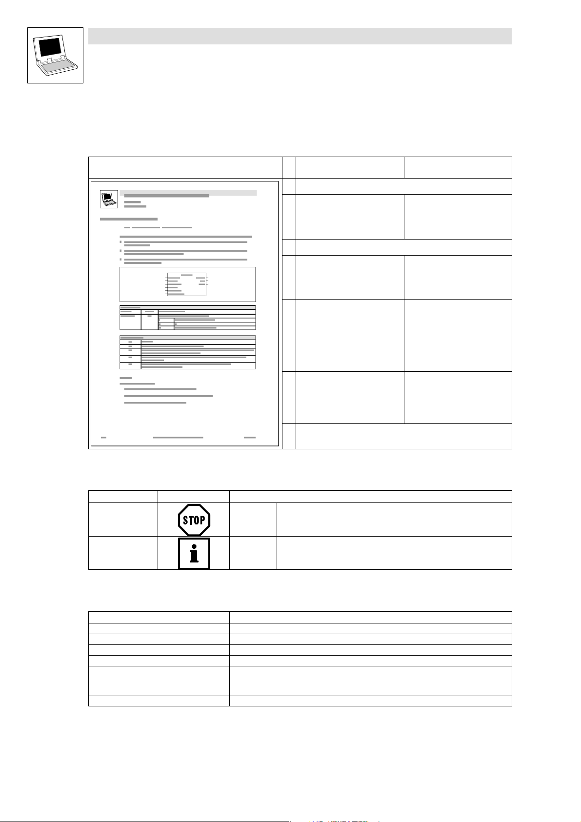
1.1.2 Description layout
All function/function block and system block descriptions contained in this Manual have the same
structure:
Function Function block (FB)/
Heading stating function and function identifier
Declaration of the function:
Data type of the return value
Function identifier
List of transfer parameters
Short description of the most important properties
Function chart including all
associated variables
Transfer parameters
Return value
Table giving information about the
transfer parameters:
Identifiers
Data type
Possible settings
Info
Table giving information about the
return value:
Data type of the return value
Possible return values and their
meaning
Additional information
(Notes, tips, application examples, etc.)
system block (SB)
−
FB/SB chart including all
associated variables
Input variables
Output variables
Table giving information about the
input and output variables:
Identifiers
Data type
Variable type
Possible settings
Info
−
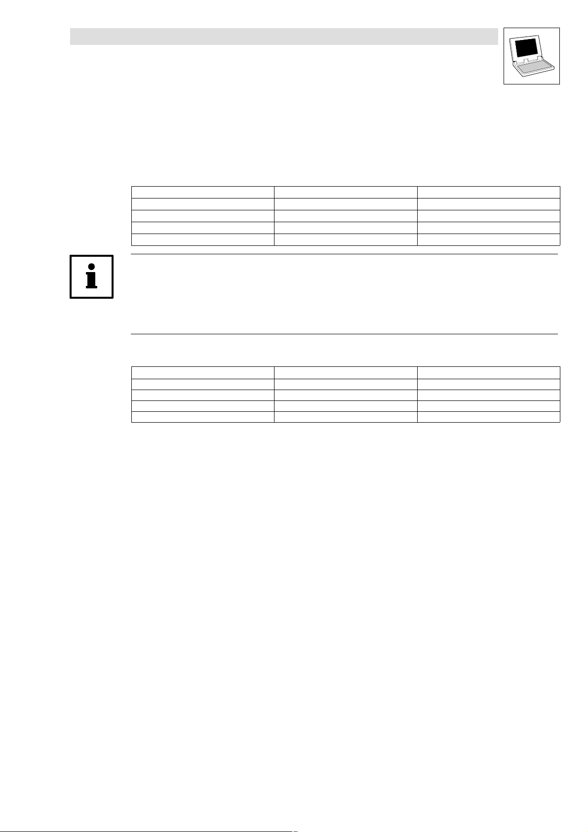
1.1.3 Pictographs used in this Manual
Pictographs used Signal words
Warning of material
damage
Other notes Tip!
Stop! Warns of potential damage to material.
Note!
1.1.4 Terminology used
Term In the following text used for
DDS Drive PLC Developer Studio
FB Function block
GDC Global Drive Control (parameterization program from Lenze)
Parameter codes Codes for setting the functionality of a function block
PLC 9300 Servo PLC
SB System block
Drive PLC
ECSxA "Application" axis module
Possible consequences if disregarded:
Damage to the controller/drive system or its environment.
Indicates a tip or note.
1−2
LenzeDrive.lib EN 1.7
L
Page 7

Function library LenzeDrive.lib
Preface and general information
1.2 Lenze software guidelines for variable names
1.2 Lenze software guidelines for variable names
The previous concepts for Lenze controllers were based on codes that represented the input and
output signals, and the parameters of function blocks.
For the sake of clarity, names were defined for the codes in the documentation.
In addition, the signal types were defined by graphical symbols.
The user could see at a glance which kind of signal (analog, phase−angle etc.) had to be present at
the particular interface.
The concept for the new automation system does not use direct codes in the
programming. The IEC 61131−3 standard is used instead.
This standard is based on a structure of variable names.
If the user applies variables in his project, then he can name the variables as he chooses.
In order to avoid the growth of a multitude of different conventions for naming variables in existing
and future projects and function libraries that are programmed by Lenze personnel, we have set up
software guidelines that must be followed by all Lenze staff.
In this convention for creating variable names, Lenze keeps to the Hungarian Notation that has been
specifically expanded by Lenze.
If you make use of Lenze−specific functions or function blocks, you will immediately be able to see,
for instance, which data type you must transfer to a function block, and which type of data you will
receive as an output value.
1.2.1 Hungarian Notation
These conventions are used so that the most significant characteristics of a program variable can
instantly be recognized from its name.
Variable names
consist of
a prefix (optional)
a data−type entry
and an identifier
The prefix and data−type entry are usually formed by one or two characters. The identifier (the
"proper" name) should indicate the application, and is therefore usually somewhat longer.
Prefix examples
prefix Meaning
a Array (combined type), field
p Pointer
L
LenzeDrive.lib EN 1.7
1−3
Page 8

Function library LenzeDrive.lib
Preface and general information
1.2 Lenze software guidelines for variable names
Examples of the data−type entry
Examples of a data−type Meaning
b Bool
by Byte
n Integer
w Word
dn Double integer
dw Double word
s String
f Real (float)
sn Short integer
t Time
un Unsigned integer
udn Unsigned double integer
usn Unsigned short integer
Identifier (the proper variable name)
An identifier begins with a capital letter.
If an identifier is assembled from several "words", then each "word" must start with a capital
letter.
All other letters are written in lower case.
Examples:
Array of integers anJogValue[10] ;
Bool bIsEmpty ;
Word wNumberOfValues ;
Integer nLoop ;
Byte byCurrentSelectedJogValue ;
1.2.1.1 Recommendation for designating variable types
In order to be able to recognize the type of variable in a program according to the name, it makes
sense to use the following designations, which are placed in front of the proper variable name and
separated from it by an underline stroke:
I_<Variablename> VAR_INPUT
Q_<Variablename> VAR_OUTPUT
IQ_<Variablename> VAR_IN_OUT
R_<Variablename> VAR RETAIN
C_<Variablename> VAR CONSTANT
CR_<Variablename> VAR CONSTANT RETAIN
g_<Variablename> VAR_GLOBAL
gR_<Variablename> VAR_GLOBAL RETAIN
gC_<Variablename> VAR_GLOBAL CONSTANT
gCR_<Variablename> VAR_GLOBAL CONSTANT RETAIN
1−4
Example
for a global array of type integer that includes fixed setpoints (analog) for a speed setting:
g_anFixSetSpeedValue_a
LenzeDrive.lib EN 1.7
L
Page 9
Function library LenzeDrive.lib
Preface and general information
1.2 Lenze software guidelines for variable names
1.2.1.2 Designation of the signal type in the variable name
The inputs and outputs of the Lenze function blocks each have a specific signal type assigned. These
may be: digital, analog, position, or speed signals.
For this reason, each variable name has an ending attached that provides information on the type of
signal.
Signal type Ending Previous designation
analog _a (analog)
digital _b (binary)
Phase−angle difference or speed _v (velocity)
Phase−angle or position _p (position)
Tip!
Normalizing to signal type phase−angle difference/speed: 16384 (INT) ¢ 15000 rpm
Normalizing to signal type analog: 16384 ¢ 100 % ¢ value under [C0011] = n
Normalizing to signal type angle or position: 65536 ¢ 1 motor revolution
H
G
F
E
max
Examples:
Variable name Signal type Type of variable
nIn_a Analog input value Integer
dnPhiSet_p Phase signals Double integer
bLoad_b Binary value (TRUE/FALSE) Bool
nDigitalFrequencyIn_v Speed input value Integer
1.2.1.3 Special handling of system variables
System variables require special handling, since the system functions are only available for the user
as I/O connections in the control configuration.
In order to be able to access a system variable quickly during programming, the variable name must
include a label for the system function.
For this reason, the name of the corresponding system block is placed before the name of the
variable.
Examples:
AIN1_nIn_a
CAN1_bCtrlTripSet_b
DIGIN_bIn3_b
L
LenzeDrive.lib EN 1.7
1−5
Page 10
Function library LenzeDrive.lib
Preface and general information
1.3 Version identifiers of the function library
1.3 Version identifiers of the function library
The version of the function library can be found under the global constant
C_w[Function library name]Version .
Version identifiers as of PLC software version 7.x:
Constant Meaning
C_w[FunctionLibraryName]VersionER External Release 01
C_w[FunctionLibraryName]VersionEL External Level 05
C_w[FunctionLibraryName]VersionIR Internal Release 00
C_w[FunctionLibraryName]VersionBN Build No. 00
The value of this constant is a hexadecimal code.
In the example, "01050000" stands for version "1.05".
Example
value
Version: 01 05 00 00
1−6
LenzeDrive.lib EN 1.7
L
Page 11

2 Function blocks
Note!
Due to their internal structure, the below function blocks have to be called in a time−equidistant task
(e.g. in a 5−ms task):
L_DIGDEL
L_DT1_
L_MPOT
L_NSET
L_ParRead
L_ParWrite
L_PCTRL
L_PHDIFF
L_PHINT
L_PHINTK
L_PT1_
L_RFG
L_SRFG
L_TRANS
Caution: The cyclic task PLC_PRG is not time−equidistant!
Function library LenzeDrive.lib
Function blocks
l
LenzeDrive.lib EN 1.7
2−1
Page 12
Function library LenzeDrive.lib
General signal processing
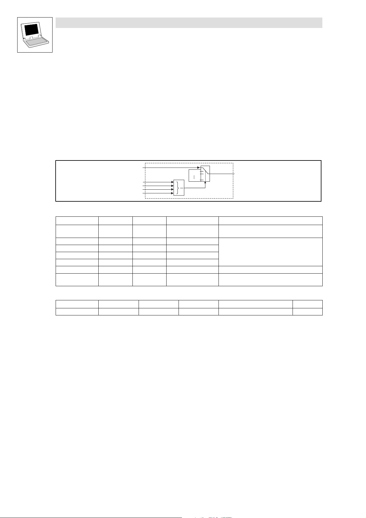
2.1.1 Programming fixed setpoints (L_FIXSET)
2.1 General signal processing
2.1.1 Programming fixed setpoints (L_FIXSET)
You can program up to 15 fixed setpoints with this FB. The addressing of the setpoint that is to be
output is made through the boolean (logic) inputs.
Fixed setpoints can be used, for example, for:
Different set dancer positions in a dancer position control
Different stretch ratios (gearbox factor) when using a speed ratio control with digital frequency
coupling
Fig. 2−1 Programming fixed setpoints (L_FIXSET)
VariableName DataType SignalType VariableType Note
nAin_a Integer analog VAR_INPUT nAin_a is connected to nOut_a , if (bIn1_b ... bIn4_b)
bIn1_b Bool binary VAR_INPUT
bIn2_b Bool binary VAR_INPUT
bIn3_b Bool binary VAR_INPUT
bIn4_b Bool binary VAR_INPUT
nOut_a Integer analog VAR_OUTPUT
anSollW[1...15] Array of integers VAR CONSTANT RETAIN Variable that can have fixed setpoints assigned to
Parameter codes of the instances
VariableName L_FIXSET1 SettingRange Lenze
anSollW[1...15] C0560/1 ... 15 −199.99 ... 199.99 % 0.00
Function
nOut_a can be used as a setpoint source (signal source) for another FB (e.g. process controller,
arithmetic block, etc.). The parameterization and handling is the same as for JOG, but it is
independent of JOG. (^ 2−73: L_NSET)
Parameterization of the fixed setpoints
– The individual fixed setpoints can be parameterized through anSollW1 ... anSollW15.
Output of the selected fixed setpoint:
– If the binary inputs are triggered with a HIGH signal, a fixed setpoint from the table is
switched to nOut_a . (^ 2−3)
Range:
– You can enter values from −199.99% ... 199.99% (100 % corresponds to 16384).
nAin_a
bIn1_b
bIn2_b
bIn3_b
bIn4_b
DMUX
0
3
FIXSET1...15
0
15
anSollW1
anSollW2
anSollW15
L_FIXSET
nOut_a
FALSE is on all the selection inputs.
The number of inputs to be assigned depends on the
number of required fixed setpoints.
them.
2−2
LenzeDrive.lib EN 1.7
L
Page 13

Function library LenzeDrive.lib
General signal processing
2.1.1 Programming fixed setpoints (L_FIXSET)
2.1.1.1 Enable of the fixed setpoints
Number of required fixed setpoints Number of the inputs to be assigned
1 at least 1
1 ... 3 at least 2
4 ... 7 at least 3
8 ... 15 4
Decoding table of the binary input signals:
Output signal
nOut_a =
nAin_a 0 0 0 0
anSollW1 1 0 0 0
anSollW2 0 1 0 0
anSollW3 1 1 0 0
anSollW4 0 0 1 0
anSollW5 1 0 1 0
anSollW6 0 1 1 0
anSollW7 1 1 1 0
anSollW8 0 0 0 1
anSollW9 1 0 0 1
anSollW10 0 1 0 1
anSollW11 1 1 0 1
anSollW12 0 0 1 1
anSollW13 1 0 1 1
anSollW14 0 1 1 1
anSollW15 1 1 1 1
0 = FALSE
1 = TRUE
1st input
bIn1_b
2nd input
bIn2_b
3rd input
bIn3_b
4th input
bIn4_b
L
LenzeDrive.lib EN 1.7
2−3
Page 14
Function library LenzeDrive.lib
Analog signal processing
2.2.1 Absolute value generation (L_ABS)
2.2 Analog signal processing
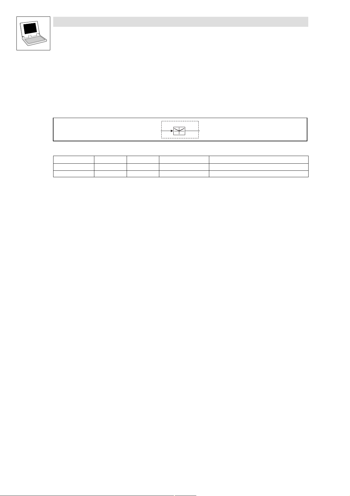
2.2.1 Absolute value generation (L_ABS)
This FB converts bipolar values into unipolar values. It calculates the absolute value of the input
signal.
Fig. 2−2 Absolute value generation (L_ABS)
VariableName DataType SignalType VariableType Note
nIn_a Integer analog VAR_INPUT
nOut_a Integer analog VAR_OUTPUT
n I n _ a
L _ A B S
n O u t _ a
2−4
LenzeDrive.lib EN 1.7
L
Page 15
Function library LenzeDrive.lib
Analog signal processing
2.2.2 Addition (L_ADD)
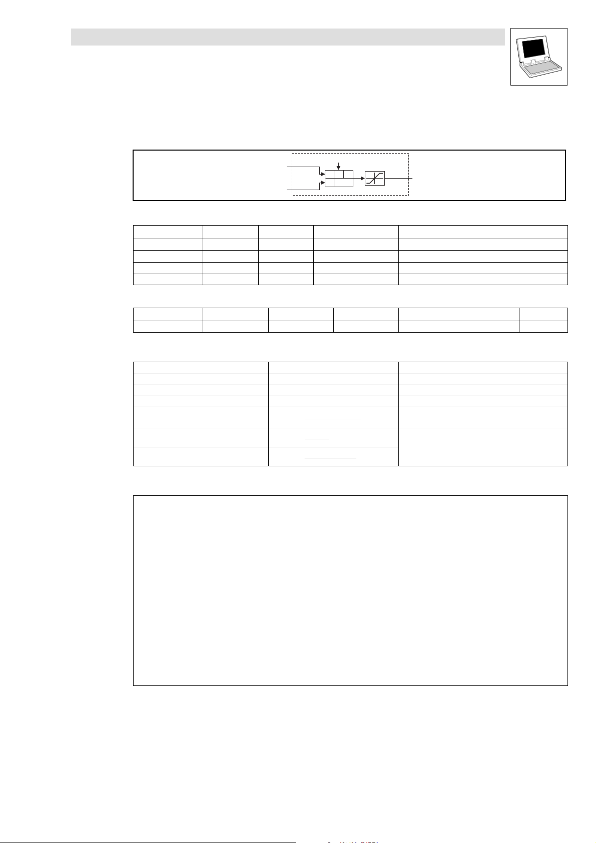
2.2.2 Addition (L_ADD)
This FB adds or subtracts input values, depending on the input that is used.
L _ A D D
± 3 2 7 6 7
Fig. 2−3 Addition (L_ADD)
VariableName DataType SignalType VariableType Note
nIn1_a Integer analog VAR_INPUT Addition input
nIn2_a Integer analog VAR_INPUT Addition input
nIn3_a Integer analog VAR_INPUT Subtraction input
nOut_a Integer analog VAR_OUTPUT Signal is limited to ±32767.
Functional sequence
1. The value at nIn1_a is added to the value of nIn2_a.
2. The value of nIn3_a is subtracted from the calculated result.
3. The result of the substraction is then limited to ±32767.
n I n 1 _ a
n I n 2 _ a
n I n 3 _ a
+
-+
n O u t _ a
L
LenzeDrive.lib EN 1.7
2−5
Page 16
Function library LenzeDrive.lib
Analog signal processing
2.2.3 Input gain and offset (L_AIN)
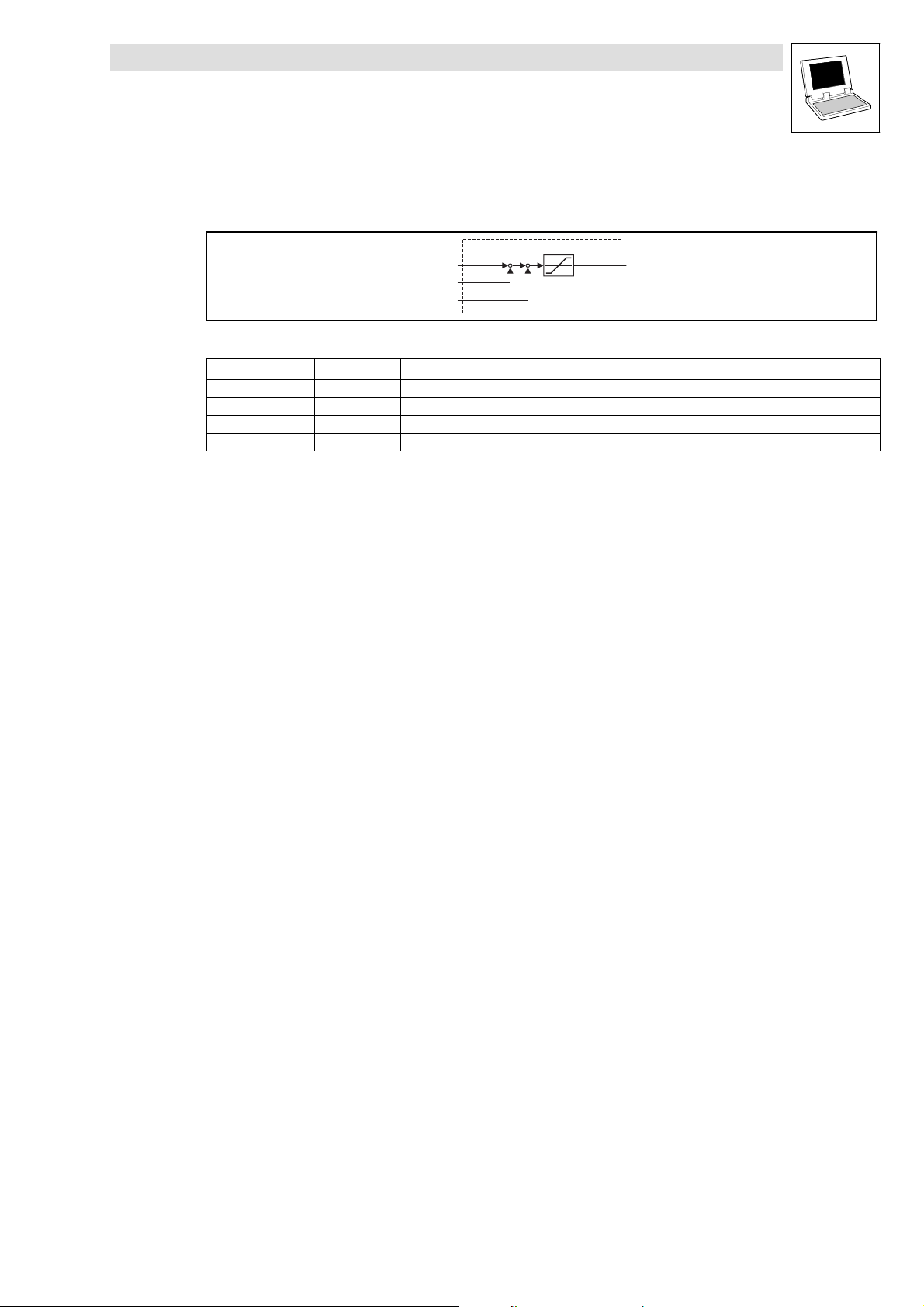
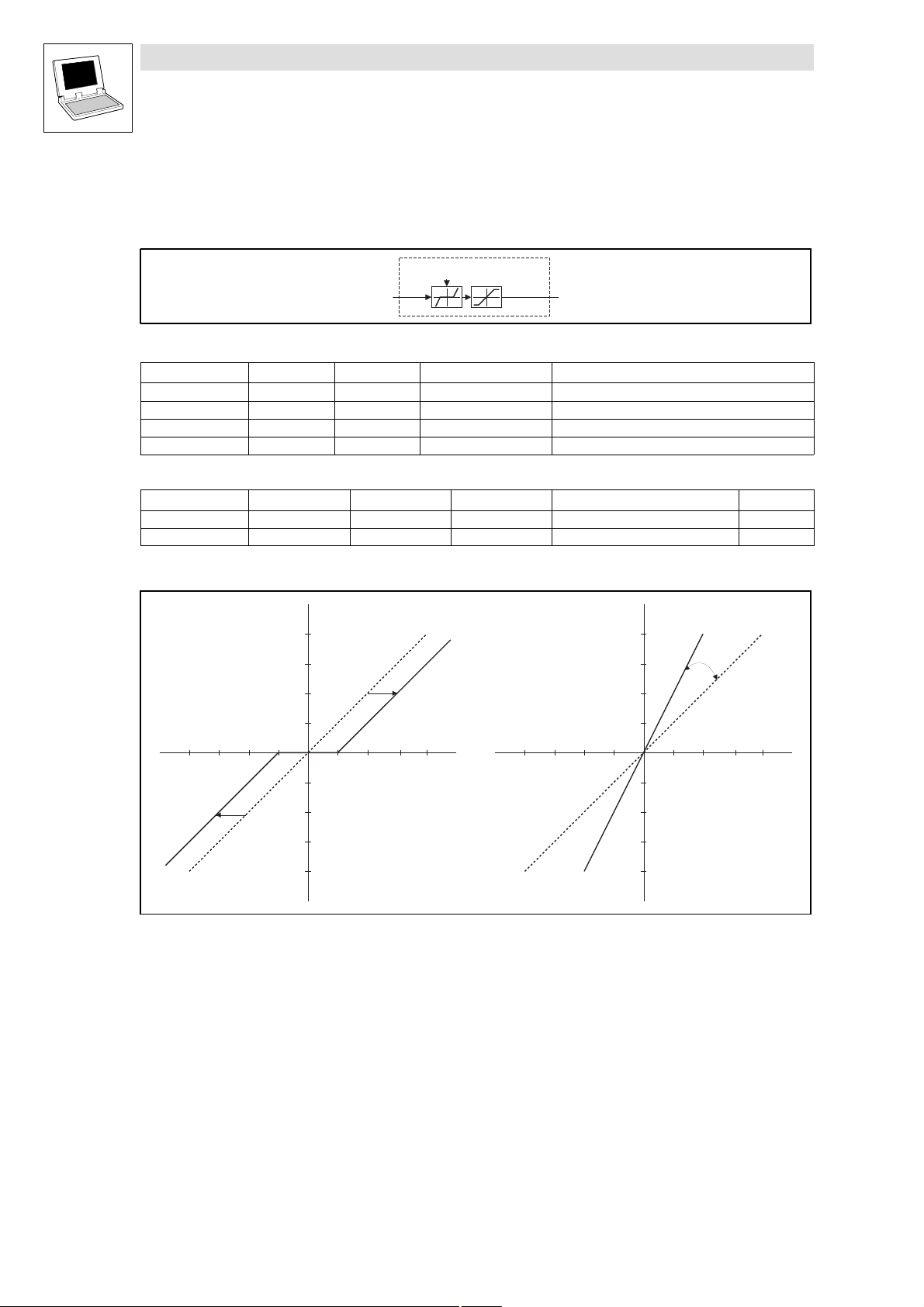
2.2.3 Input gain and offset (L_AIN)
This FB is preferentially used for addition circuitry at the analog input terminals, to adjust the gain and
offset.
Fig. 2−4 Input gain and offset (L_AIN)
VariableName DataType SignalType VariableType Note
nIn_a Integer analog VAR_INPUT Input signal
nOffset_a Integer analog VAR_INPUT Offset of the input signal
nGain_a Integer analog VAR_INPUT Gain of the input signal
nOut_a Integer analog VAR_OUTPUT
Function
Offset
– The value at nOffset_a is added to the value of nIn_a
– The result of the addition is limited to ±32767.
Gain
– The limited value (after the offset) is multiplied by the value at nGain_a .
– Next, the signal is limited to ±32767.
The signal is given out at nOut_a .
nOut_a
nIn_a
nOffset_a
nGain_a
+
+
L_AIN
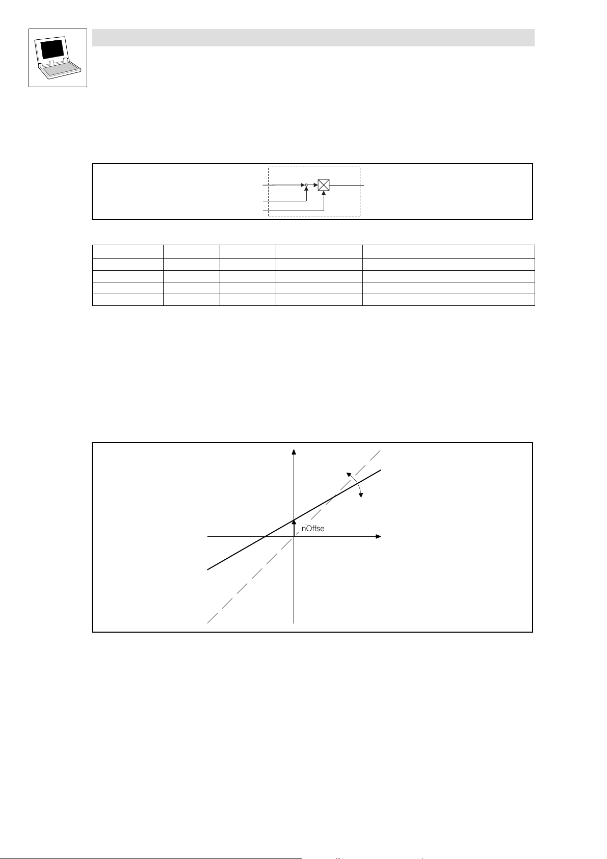
nOut_a
Fig. 2−5 Offset and gain of the analog input
nGain_a
nOffset_a
nIn_a
2−6
LenzeDrive.lib EN 1.7
L
Page 17

Function library LenzeDrive.lib
Analog signal processing
2.2.3 Input gain and offset (L_AIN)
Funtion in IL
LD nIn_a
INT_TO_DINT
ADD (nOffset_a
INT_TO_DINT
)
LIMIT −32767,32767
MUL (nGain_a
INT_TO_DINT
)
DIV 16384
LIMIT −32767,32767
DINT_TO_INT
ST nOut_a
L
LenzeDrive.lib EN 1.7
2−7
Page 18

Function library LenzeDrive.lib
Analog signal processing
2.2.4 Inversion (L_ANEG)
2.2.4 Inversion (L_ANEG)
This FB inverts the sign of an input value. The input value is multiplied by −1 and then output.
Fig. 2−6 Inversion (L_ANEG)
VariableName DataType SignalType VariableType Note
nIn_a Integer analog VAR_INPUT
nOut_a Integer analog VAR_OUTPUT
n I n _ a
* ( - 1 )
L _ A N E G
n O u t _ a
2−8
LenzeDrive.lib EN 1.7
L
Page 19
Function library LenzeDrive.lib
Analog signal processing
2.2.5 Output gain and offset (L_AOUT)
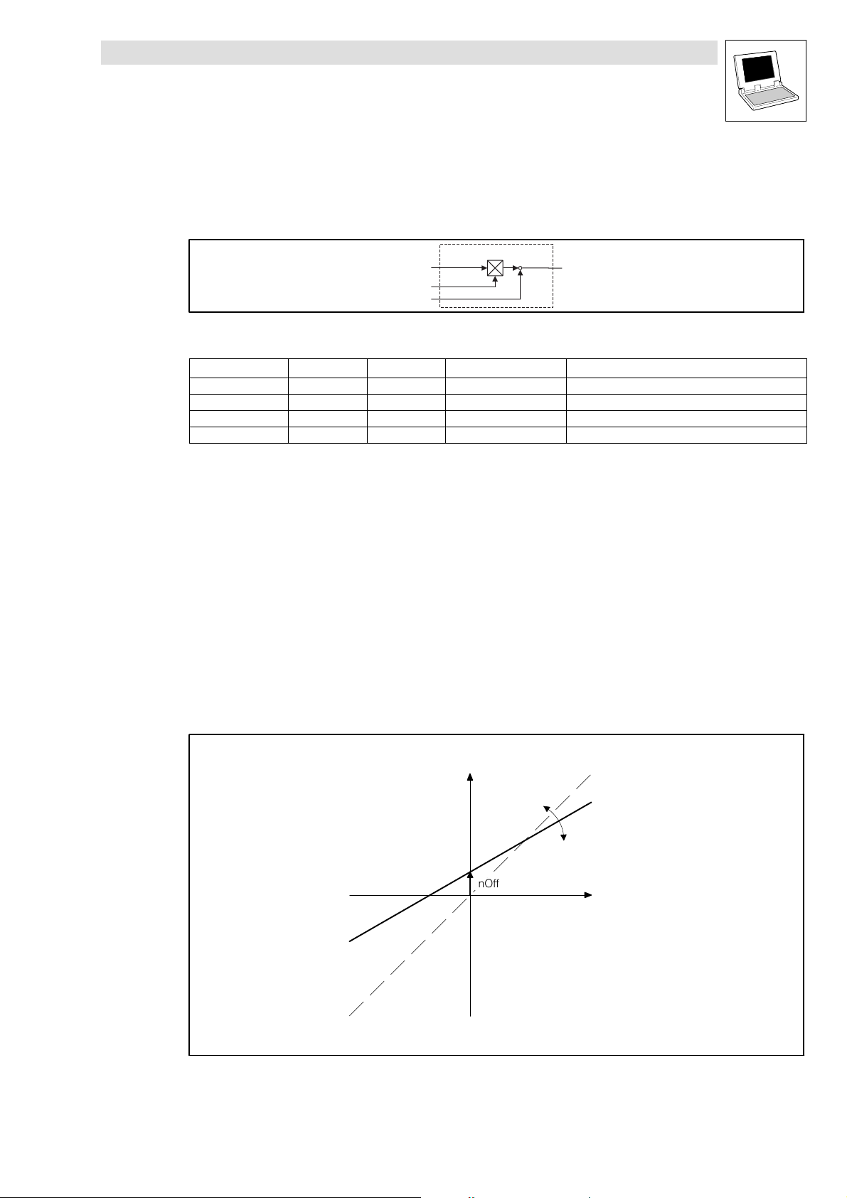
2.2.5 Output gain and offset (L_AOUT)
This FB is preferentially used for additional circuitry at analog output terminals, to adjust the gain and
offset.
L_AOUT
+
nIn_a
nGain_a
nOffset_a
Fig. 2−7 Output gain and offset (L_AOUT)
VariableName DataType SignalType VariableType Note
nIn_a Integer analog VAR_INPUT Input signal
nGain_a Integer analog VAR_INPUT Gain of the input signal
nOffset_a Integer analog VAR_INPUT Offset of the input signal
nOut_a Integer analog VAR_OUTPUT
Function
nOut_a
+
Gain
– The value at nIn_a is multiplied by the value at nGain_a .
– The multiplication is performed according to the formula:
16384 @ 16384 @ 2
*14
+ 16384
– The result of the multiplication is limited to ±2
[100% @ 100% + 100%]
14
Offset
– The limited value (after amplification) is added to the value at nOffset_a
– The result of the addition is limited to ±2
Next, the signal is limited to ±2
14
and output to nOut_a .
nOut_a
14
nGain_a
nOffset_a
nIn_a
Fig. 2−8 Offset and gain of the analog output
L
LenzeDrive.lib EN 1.7
2−9
Page 20

Function library LenzeDrive.lib
Analog signal processing
2.2.5 Output gain and offset (L_AOUT)
Function in IL
LD nIn_a
INT_TO_DINT
MUL (nGain_a
INT_TO_DINT
)
DIV −32767,32767
ADD (nOffset_a
INT_TO_DINT
)
LIMIT −32767,32767
DINT_TO_INT
ST nOut_a
2−10
LenzeDrive.lib EN 1.7
L
Page 21
Function library LenzeDrive.lib
Analog signal processing
2.2.6 Arithmetic (L_ARIT)
2.2.6 Arithmetic (L_ARIT)
This FB can arithmetically combine two analog signals.
Fig. 2−9 Arithmetic (L_ARIT)
VariableName DataType SignalType VariableType Note
nIn1_a Integer analog VAR_INPUT
nIn2_a Integer analog VAR_INPUT
nOut_a Integer analog VAR_OUTPUT The signal is limited to ±32767.
byFunction Byte VAR CONSTANT RETAIN Selection of the function
Parameter codes of the instances
VariableName L_ARIT1 L_ARIT2 SettingRange Lenze
byFunction C0338 C0600 0 ... 5 1
Function
Selection of the function Arithmetic function Notes
byFunction = 0 nOut_a = nIn1_a
byFunction = 1 nOut_a = nIn1_a + nIn2_a
byFunction = 2 nOut_a = nIn1_a − nIn2_a
byFunction = 3
byFunction = 4
byFunction = 5
nOut_a +
nOut_a +
nOut_a +
nIn1_a
nIn2_a
byFunction
x
+
y
(nIn1_a) @ (nIn2_a)
16384
nIn1_a
@ 164
|
|
nIn2 a
nIn1_a
16384 * nIn2_a
L_ARIT
±32767
*
x/(1-y)/
nOut_a
If the denominator = 0,
the denominator is set = 1.
@ 16384
Function in ST
CASE byFunktion OF
0: nOut_a:=nIn1_a;
1: nOut_a:= DINT_TO_INT ( LIMIT (−32767,( INT_TO_DINT (nIn1_a)+ INT_TO_DINT (nIn2_a)),32767));
2: nOut_a:= DINT_TO_INT ( LIMIT (−32767,( INT_TO_DINT (nIn1_a)− INT_TO_DINT (nIn2_a)),32767));
3: nOut_a:= DINT_TO_INT ( LIMIT (−32767,(( INT_TO_DINT (nIn1_a)* INT_TO_DINT (nIn2_a))/16384),32767));
4: IF (nIN2_a=0) THEN
nOut_a= DINT_TO_INT ( LIMIT (−32767,(( INT_TO_DINT (nIn1_a)*164)),32767));
ELSE
nOut_a= DINT_TO_INT ( LIMIT (−32767,(( INT_TO_DINT (nIn1_a)*164)/ ABS (nIn2_a)),32767));
END_IF
5: IF (16384− INT_TO_DINT (nIn2_a)=0) THEN
nOut_a= DINT_TO_INT ( LIMIT (−32767,(( INT_TO_DINT (nIn1_a)*16384),32767));
ELSIF (16384− INT_TO_DINT (nIn2_a)>32767) THEN
nOut_a= DINT_TO_INT ( LIMIT (−32767,(( INT_TO_DINT (nIn1_a)*16384/32767),32767));
ELSIF (16384− INT_TO_DINT (nIn2_a)<−32767) THEN
nOut_a= DINT_TO_INT ( LIMIT (−32767,(( INT_TO_DINT (nIn1_a)*16384/−32767),32767));
ELSE
nOut_a= DINT_TO_INT ( LIMIT (−32767,(( INT_TO_DINT (nIn1_a)*16384)/(16384− INT_TO_DINT (nIn2_a)))
END_IF
END_CASE ;
L
LenzeDrive.lib EN 1.7
2−11
Page 22
Function library LenzeDrive.lib
Analog signal processing
2.2.7 Changeover (L_ASW)
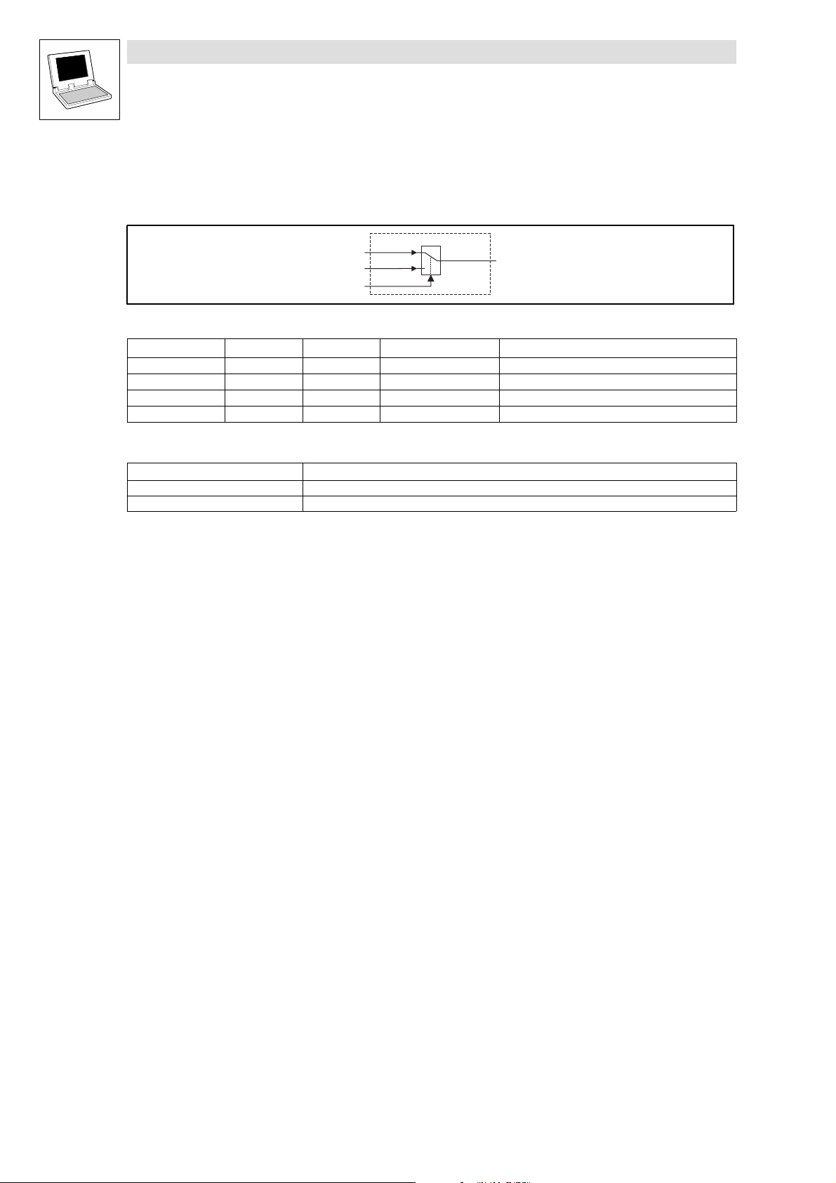
2.2.7 Changeover (L_ASW)
This FB switches between two integer values. So it is, for example, possible to change between an
initial diameter and a calculated diameter during winding.
Fig. 2−10 Changeover (L_ASW)
VariableName DataType SignalType VariableType Note
nIn1_a Integer analog VAR_INPUT
nIn2_a Integer analog VAR_INPUT
bSet_b Bool binary VAR_INPUT
nOut_a Integer analog VAR_OUTPUT
Function
Control signal Output signal
bSet_b = TRUE nOut_a = nIn2_a
bSet_b = FALSE nOut_a = nIn1_a
n I n 1 _ a
n I n 2 _ a
b S e t _ b
L _ A S W
0
n O u t _ a
1
2−12
LenzeDrive.lib EN 1.7
L
Page 23
Function library LenzeDrive.lib
Analog signal processing
2.2.8 Comparison (L_CMP)
2.2.8 Comparison (L_CMP)
This FB compares two integer values with each other. You can use comparators to implement
threshold switches.
Fig. 2−11 Comparison (L_CMP)
VariableName DataType SignalType VariableType Note
nIn1_a Integer analog VAR_INPUT
nIn2_a Integer analog VAR_INPUT
bOut_b Bool binary VAR_OUTPUT
byFunction Byte VAR CONSTANT RETAIN Comparison function for the inputs
nHysteresis Integer VAR CONSTANT RETAIN Hysteresis function
nWindow Integer VAR CONSTANT RETAIN Window function
Parameter codes of the instances
VariableName L_CMP1 L_CMP2 L_CMP3 SettingRange Lenze
byFunction C0680 C0685 C0690 1 ... 6 6
nHysteresis C0681 C0686 C0691 0.00 ... 100.00 % 1.00
nWindow C0682 C0687 C0692 0.00 ... 100.00 % 1.00
Function
Selection of the function Comparison function
byFunction = 1 nIn1_a = nIn2_a
byFunction = 2 nIn1_a > nIn2_a
byFunction = 3 nIn1_a < nIn2_a
byFunction = 4 nIn1_a = nIn2_a
byFunction = 5 nIn1_a > nIn2_a
byFunction = 6 nIn1_a < nIn2_a
b y F u n c t i o n
n H y s t e r e s i s
n I n 1 _ a b O u t _ b
n I n 2 _ a
L _ C M P
n W i n d o w
L
LenzeDrive.lib EN 1.7
2−13
Page 24
Function library LenzeDrive.lib
Analog signal processing
2.2.8 Comparison (L_CMP)
2.2.8.1 Function 1: nIn1_a = nIn2_a
Selection: byFunction = 1
This function compares two signals for equality. For instance, you can make the V comparison
"actual speed is equal to set speed" (n
The exact function can be seen in the diagram. (^Fig. 2−12)
nWindow
nHysteresis
1
nWindow
act
nHysteresis
= n
set
).
0
nIn1_a
nHysteresis
nWindow
nIn2_a
nWindow
nHysteresis
bOut_b
Fig. 2−12 Equality of signals (nIn1_a = nIn2_a)
Use nWindow to set the window within which the equality is valid.
Use nHysteresis to set a hysteresis, if the input signals are not stable and the output oscillates.
nIn2_a
nIn1_a
t
t
2−14
Note!
With this function, you must use the FB in a fast task, to achieve optimum sampling of the signals.
LenzeDrive.lib EN 1.7
L
Page 25
Function library LenzeDrive.lib
Analog signal processing
2.2.8 Comparison (L_CMP)
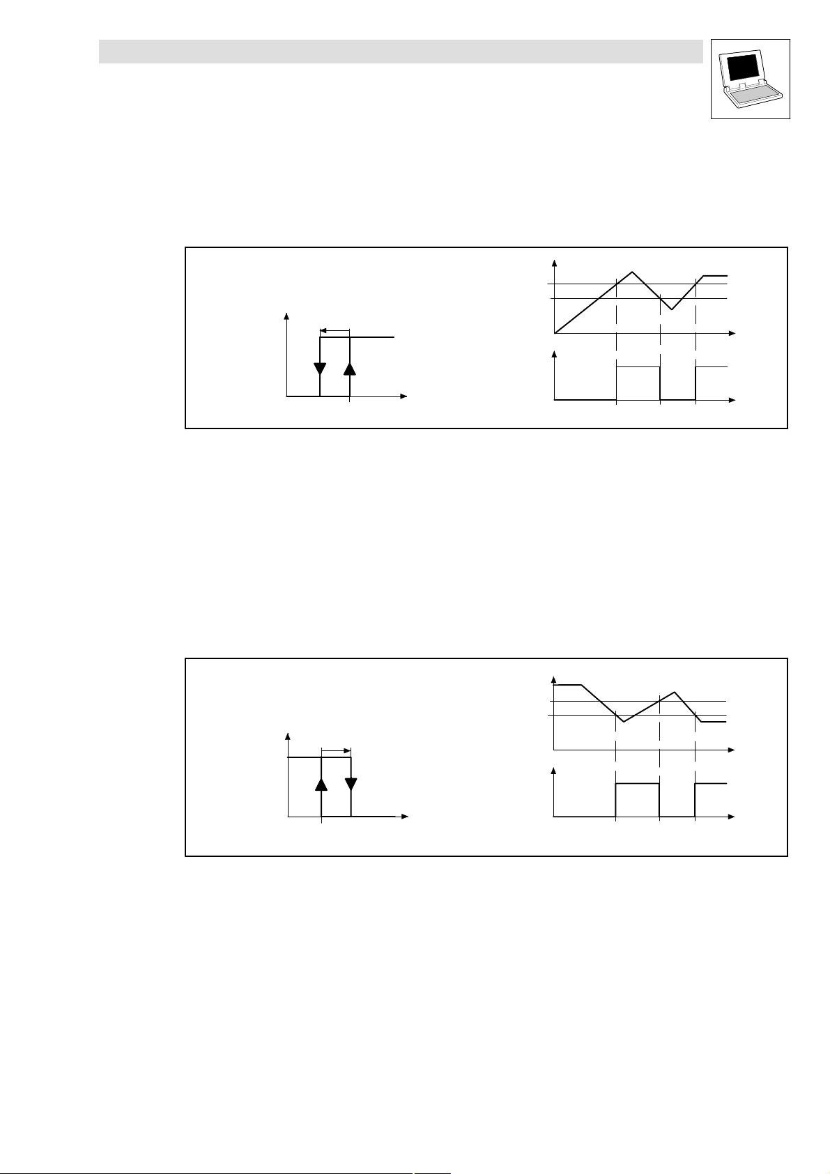
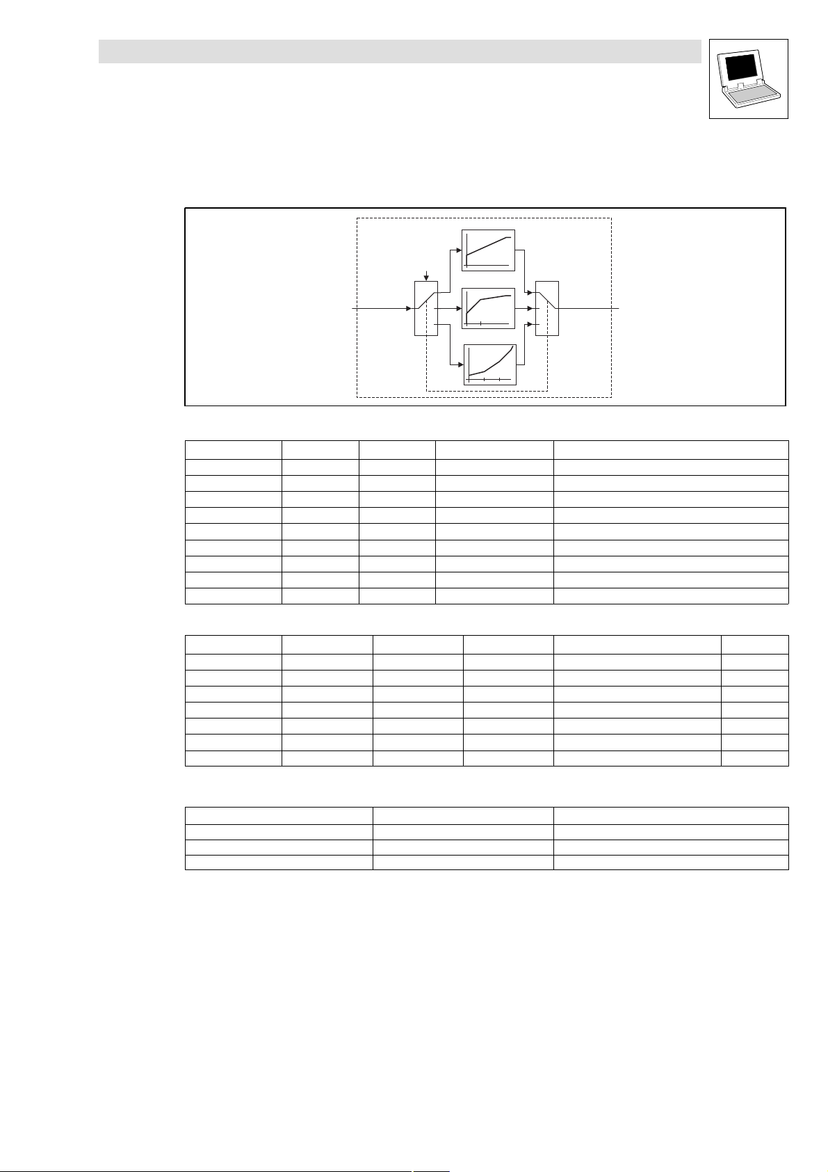
2.2.8.2 Function 2: nIn1_a > nIn2_a
Selection: byFunction = 2
With this function, you can make the comparison "actual speed is above a limit" (n
one direction of rotation.
nIn1_a
nIn2_a
nHysteresis
bOut_b
nHysteresis
1
bOut_b
> nx ) for
act
t
0
Fig. 2−13 Signal values exceeded (nIn1_a > nIn2_a)
Functional sequence
1. If the value at nIn1_a is below the value at nIn2_a, then bOut_b changes from FALSE to TRUE.
2. Only when the signal at nIn1_a is above the value of nIn2_a − nHysteresis again, will bOut_b
change from TRUE to FALSE.
2.2.8.3 Function 3: nIn1_a < nIn2_a
Selection: byFunction = 3
With this function, for instance, you can make the comparison "actual speed is below a limit"
(n
< nx ) for one direction of rotation.
act
bOut_b
nHysteresis
1
nIn1_anIn2_a
nIn1_a
nHysteresis
nIn2_a
bOutb_b
t
t
0
nIn2_a
Fig. 2−14 Gone below signal values (nIn1_a < nIn2_a)
nIn1_a
Functional sequence
1. If the value at nIn1_a is below the value at nIn2_a, then bOut_b changes from FALSE to TRUE.
2. Only when the signal at nIn1_a is above the value of nIn2_a − nHysteresis again, will bOut_b
change from TRUE to FALSE.
L
LenzeDrive.lib EN 1.7
t
2−15
Page 26

Function library LenzeDrive.lib
Analog signal processing
2.2.8 Comparison (L_CMP)
2.2.8.4 Function 4: |nIn1_a| = |nIn2_a|
Selection: byFunction = 4
With this function, for instance, you can make the comparison "n
This function is the same as function 1. (^ 2−14)
– However, the absolute value of the input signals (without sign) is generated here before the
signal processing.
2.2.8.5 Function 5: |nIn1_a| > |nIn2_a|
Selection: byFunction = 5
With this function, for instance, you can make the comparison "n
the direction of rotation.
This function is the same as function 2. (^ 2−15)
– However, the absolute value of the input signals (without sign) is generated here before the
signal processing.
= 0".
act
| > |nx |" independently of
act
2.2.8.6 Function 6: |nIn1_a| < |nIn2_a|
Selection: byFunction = 6
With this function, you can make the comparison "n
of rotation.
This function is the same as function 3. (^ 2−15)
– However, the absolute value of the input signals (without sign) is generated here before the
signal processing.
| < |nx |" independently of the direction
act
2−16
LenzeDrive.lib EN 1.7
L
Page 27
Function library LenzeDrive.lib
Analog signal processing
2.2.9 Curve function (L_CURVE)
2.2.9 Curve function (L_CURVE)
This FB converts an analog signal into a characteristic curve.
Fig. 2−15 Curve function (L_CURVE)
VariableName DataType SignalType VariableType Note
nIn_a Integer analog VAR_INPUT
nOut_a Integer analog VAR_OUTPUT
byFunction Byte VAR CONSTANT RETAIN Selection of the characteristic/curve function
nY0 Integer VAR CONSTANT RETAIN Entry of Y0 from vector (0, Y0)
nY1 Integer VAR CONSTANT RETAIN Entry of Y1 from vector (X1, Y1)
nY2 Integer VAR CONSTANT RETAIN Entry of Y2 from vector (X2, Y2)
nY100 Integer VAR CONSTANT RETAIN Entry of Y100 from vector (16384, Y100)
nX1 Integer VAR CONSTANT RETAIN Entry of X1 from vector (X1, Y1)
nX2 Integer VAR CONSTANT RETAIN Entry of X2 from vector (X2, Y2)
Parameter codes of the instances
nIn_a
Y0 = nY0
Y1 = nY1
Y2 = nY2
Y100 = nY100
X1 = nX1
X2 = nX2
byFunction
1
2
3
Characteristic 1
y
y100
y0
Characteristic 2
y
y100
y1
y0
x1
Characteristic 3
y
y100
y2
y1
y0
x1 x2
L_CURVE
x
1
2
3
x
x
nOut_a
VariableName L_CURVE1 SettingRange Lenze
byFunction C0960 1 ... 3 1
nY0 C0961 0 ... 199.99 % 0.00
nY1 C0962 0 ... 199.99 % 50.00
nY2 C0963 0 ... 199.99 % 75.00
nY100 C0964 0 ... 199.99 % 100.00
nX1 C0965 0.01 ... 99.99 % 50.00
nX2 C0966 0.01 ... 99.99 % 75.00
Function
Selection of the function Curve function Informationen for entry of the interpolation points
byFunction = 1 Characteristic with two co−ordinates ^ Fig. 2−16
byFunction = 2 Characteristic with three co−ordinates ^ Fig. 2−17
byFunction = 3 Characteristic with four interpolatio points ^ Fig. 2−18
100% corresponds to 16384.
A linear interpolation is carried out between the co−ordinates.
For negative values at nIn_a the settings of the interpolation points are processed inversely
(see line diagrams).
– If this is not required, insert an FB L_ABS or an FB L_LIM before or after the FB L_CURVE.
L
LenzeDrive.lib EN 1.7
2−17
Page 28
Function library LenzeDrive.lib
a
Analog signal processing
2.2.9 Curve function (L_CURVE)
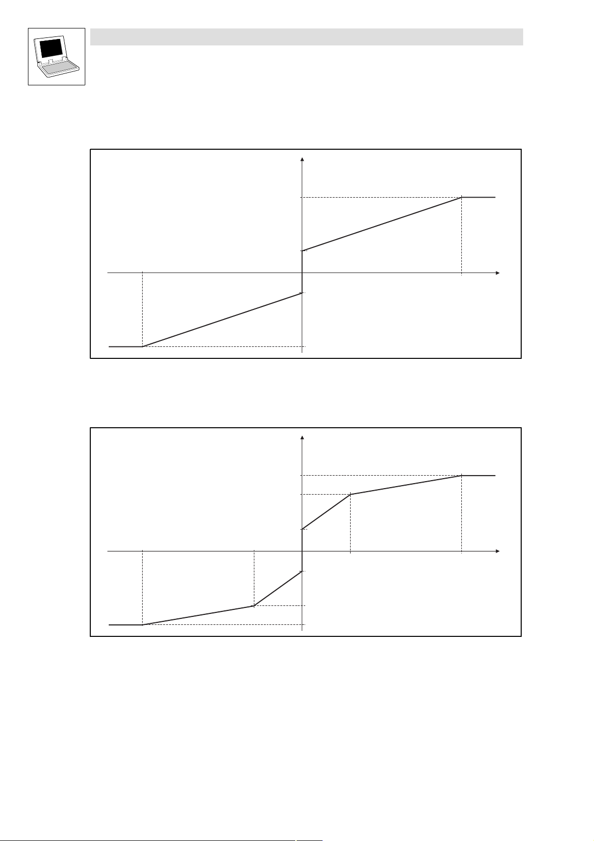
2.2.9.1 Characteristic with two co−ordinates
byFunction = 1
y
n O u t _ a
n Y 1 0 0
n Y 0
- 1 0 0 %
Fig. 2−16 Line diagram with 2 co−ordinates
2.2.9.2 Characteristic with three co−ordinates
byFunction = 2
y
n O u t _ a
n Y 1 0 0
n Y 1
y 0
- n Y 0
- n Y 1 0 0
y 1 0 0
1 0 0 %
y 1 0 0
y 1
x
n I n _
- 1 0 0 %
Fig. 2−17 Line diagram with 3 co−ordinates
2−18
n Y 0
y 0
- n X 1
- Y 0
- n Y 1
- n Y 1 0 0
LenzeDrive.lib EN 1.7
x 1
n X 2 1 0 0 %
x
n I n _ a
L
Page 29
Function library LenzeDrive.lib
a
Analog signal processing
2.2.9 Curve function (L_CURVE)
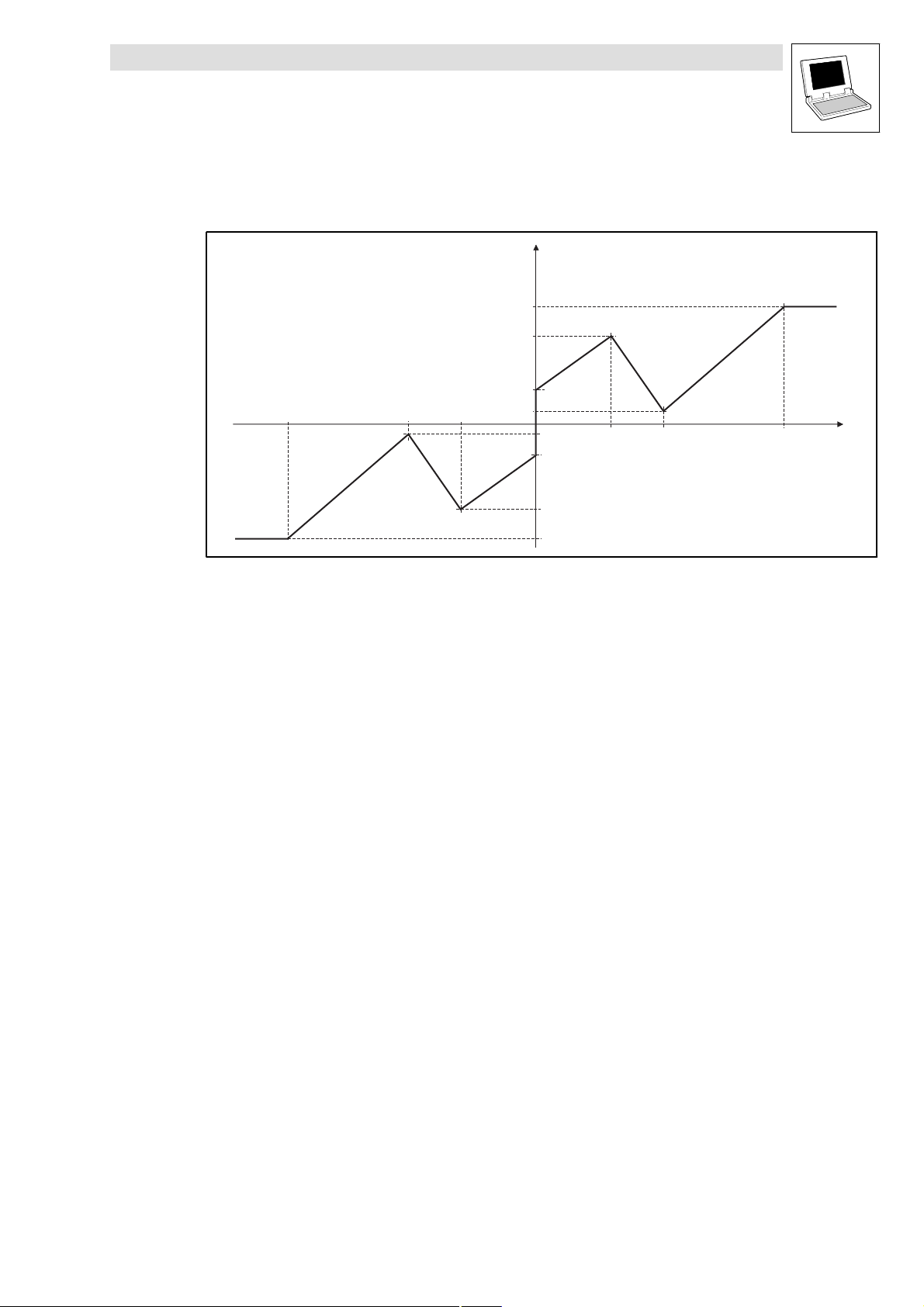
2.2.9.3 Characteristic with four co−ordinates
byFunction = 3
y
n O u t _ a
- 1 0 0 %
Fig. 2−18 Line diagram characteristic with 4 co−ordinates
- n X 1- n X 2
n Y 1 0 0
n Y 1
n Y 0
n Y 2
y 0
- n Y 2
- n Y 0
- n Y 1
- n Y 1 0 0
y 1 0 0
y 1
y 2
x 1 x 2
n X 1 n X 2 1 0 0 %
x
n I n _
L
LenzeDrive.lib EN 1.7
2−19
Page 30
Function library LenzeDrive.lib
Analog signal processing
2.2.10 Dead−band (L_DB)
2.2.10 Dead−band (L_DB)
This FB eliminates disturbances around the zero point (e.g. interfering influences on analog input
voltages).
Fig. 2−19 Dead band (L_DB)
VariableName DataType SignalType VariableType Note
nIn_a Integer analog VAR_INPUT
nOut_a Integer analog VAR_OUTPUT The signal is limited to ±32767.
nGain Integer − VAR CONSTANT RETAIN Gain
nDeadBand Integer − VAR CONSTANT RETAIN Dead band
Parameter codes of the instances
VariableName L_DB1 SettingRange Lenze
nGain C0620 −10.00 ... 10.00 1.00
nDeadBand C0621 0 ... 100.00 % 1.00
Function
n G a i n = 1 , 0 0
n D e a d B a n d = 6 , 1 0 % = 1 0 0 0
n O u t _ a
n D e a d B a n d
nIn_a
nGain
nDeadBand
±32767
L_DB
nOut_a
n G a i n = 2 , 0 0
n D e a d B a n d = 0 %
n O u t _ a
n G a i n
n D e a d B a n d
Fig. 2−20 Dead band and gain
In nDeadBand you can set the parameters for the dead band.
In nGain you can alter the gain.
100 % corresponds to 16384.
n I n _ a
n I n _ a
2−20
LenzeDrive.lib EN 1.7
L
Page 31

Function library LenzeDrive.lib
Analog signal processing
2.2.11 Differentiation (L_DT1_)
2.2.11 Differentiation (L_DT1_)
This FB differentiates signals. You can use it, for instance, for the acceleration injection (dv/dt).
Fig. 2−21 Differentiation (L_DT1_)
VariableName DataType SignalType VariableType Note
nIn_a Integer analog VAR_INPUT
nOut_a Integer analog VAR_OUTPUT The signal is limited to ±32767.
nGain Integer VAR CONSTANT RETAIN Gain K
nDelayTime Integer VAR CONSTANT RETAIN Delay time T
bySensibility Byte VAR CONSTANT RETAIN Input sensitivity of nIn_a
Parameter codes of the instances
VariableName L_DT1_1 SettingRange Lenze
nGain C0650 −320.00 ... 320.00 1.00
nDelayTime C0651 0.005 ... 5.000 s 1.000
bySensibility C0653 1 ... 7 1
Function
Selection of the function Function
bySensibility = 1 15 Bit
bySensibility = 2 14 Bit
bySensibility = 3 13 Bit
bySensibility = 4 12 Bit
bySensibility = 5 11 Bit
bySensibility = 6 10 bit
bySensibility = 7 9 Bit
nIn_a
bySensibility
nGain
nDelayTime
±32767
L_DT1_
nOut_a
loss
The FB only evaluates the specified most significant
bits, according to the setting.
Fig. 2−22 Delay time T
L
K
of the 1st order differential section
loss
LenzeDrive.lib EN 1.7
T
loss
t
2−21
Page 32

Function library LenzeDrive.lib
Analog signal processing
2.2.12 Limiting (L_LIM)
2.2.12 Limiting (L_LIM)
This FB limits signals to preset ranges of values. You can fix the range of values by defining an upper
and a lower limit.
Fig. 2−23 Limiting (L_LIM)
VariableName DataType SignalType VariableType Note
nIn_a Integer analog/velocity VAR_INPUT
nOut_a Integer analog/velocity VAR_OUTPUT
nMaxLimit Integer VAR CONSTANT RETAIN Defines the upper limit. (100 % 16384)
nMinLimit Integer VAR CONSTANT RETAIN Defines the lower limit. (100 % 16384)
Parameter codes of the instances
VariableName L_LIM1 SettingRange Lenze
nMaxLimit C0630 −199.99 ... 199.99 % 100.00
nMinLimit C0631 −199.99 ... 199.99 % −100.00
Note!
The lower limit must always be set lower than the upper limit.
Otherwise nOut_a is set = 0.
n I n _ a
n M a x L i m i t
n M i n L i m i t
L _ L I M
n O u t _ a
2−22
LenzeDrive.lib EN 1.7
L
Page 33

Function library LenzeDrive.lib
Analog signal processing
2.2.13 Delay (L_PT1_)
2.2.13 Delay (L_PT1_)
This FB filters and delays analog signals.
Fig. 2−24 Delay (L_PT1_)
VariableName DataType SignalType VariableType Note
nIn_a Integer analog VAR_INPUT
nOut_a Integer analog VAR_OUTPUT
nDelayTime Integer VAR CONSTANT RETAIN Time constant
Parameter codes of the instances
VariableName L_PT1_1 SettingRange Lenze
nDelayTime C0640 0.01 ... 50.00 20.00
Function
K=1
nDelayTime
nIn_a
T
L_PT1_
nOut_a
t
Fig. 2−25 Delay T of the first−order delay element
Use the constant nDelayTime to set the delay time.
The proportional value is fixed at K = 1 .
L
LenzeDrive.lib EN 1.7
2−23
Page 34

Function library LenzeDrive.lib
Analog signal processing
2.2.14 Ramp generator (L_RFG)
2.2.14 Ramp generator (L_RFG)
This FB functions as a ramp generator to control the rate of rise of signals.
Fig. 2−26 Ramp generator (L_RFG)
VariableName DataType SignalType VariableType Note
nIn_a Integer analog/velocity VAR_INPUT
nSet_a Integer analog/velocity VAR_INPUT
bLoad_b Boo binary VAR_INPUT
nOut_a Integer analog/velocity VAR_OUTPUT
dnTir Double Integer VAR CONSTANT RETAIN Acceleration time T
dnTif Double Integer VAR CONSTANT RETAIN Deceleration time T
Parameter codes of the instances
n I n _ a
n S e t _ a
b L o a d _ b
d n T i r
L _ R F G
d n T i f
n O u t _ a
0
1
ir
if
Variable name L_RFG1 SettingRange Lenze
dnTir C0671 0.000 ... 999.999 s 0.000
dnTif C0672 0.000 ... 999.999 s 0.000
Range of functions
Calculation and setting of the acceleration and deceleration times
Loading of the ramp generator
2−24
LenzeDrive.lib EN 1.7
L
Page 35

Function library LenzeDrive.lib
Analog signal processing
2.2.14 Ramp generator (L_RFG)
2.2.14.1 Calculation and setting of the acceleration and deceleration times
The acceleration time and deceleration times refer to a change of the output value from 0 to 100 %
(100% = 16384). The times to be set: Tir and Tif can be calculated from the formula in Fig. 2−27:
[%]
nOut_a
100%
w2
w1
0
t
ir
T
ir
t
if
T
if
t
Tir+ t
Fig. 2−27 Acceleration and deceleration times of L_RFG
w1, w2 Change of the main setpoint, depending on tir resp. t
100%
ir
w2 * w1
Here tir and tif are the required times for the change between w1 and w2. The calculated values T
and Tif are entered under dnTir and dnTif.
2.2.14.2 Loading of the ramp generator
By using nSet_a and bLoad_b you can initialize the ramp generator with defined values.
As long as bLoad_b = TRUE, the signal at nSet_a is output to nOut_a.
If bLoad_b is set = FALSE, then the ramp generator runs with the preset T
loaded value through nSet_a to the value at nIn_a.
Note!
16384 100 % C0011 (n
max
)
Tif+ t
if
100%
if
w2 * w1
−times from the
i
ir
L
LenzeDrive.lib EN 1.7
2−25
Page 36

Function library LenzeDrive.lib
Analog signal processing
2.2.15 Sample & Hold (L_SH)
2.2.15 Sample & Hold (L_SH)
This FB can store analog signals. The stored value is also available after mains disconnection.
Fig. 2−28 Sample & Hold (L_SH)
VariableName DataType SignalType VariableType Note
nIn_a Integer analog/velocity VAR_INPUT
bLoad_b Bool binary VAR_INPUT FALSE = store
nOut_a Integer analog/velocity VAR_OUTPUT
nCurValRetain Integer VAR_GLOBAL RETAIN
Function
By using bLoad_b = TRUE the signal at nIn_a is switched to nOut_a.
By using bLoad_b = FALSE the last valid value is stored and output at nOut_a. A signal change
at nIn_a does not produce any change at nOut_a.
Storing in the case of mains disconnection:
– Set bLoad_b = FALSE, when the supply voltage is switched off (either mains/line supply,
DC−bus, or voltage supply of the control terminals).
– Set bLoad_b = FALSE, when the supply voltage is switched on again (either mains/line
supply, DC−bus, or voltage supply of the control terminals).
n I n _ a
b L o a d _ b
S & H
n C u r V a l R e t a i n
L _ S H
n O u t _ a
Store the present output value after power interruption
L _ S H
S & H
n C u r V a l R e t a i n
n O u t _ a
n I n _ a
b L o a d _ b
[ V A R _ G L O B A L R E T A I N ]
Fig. 2−29 Programming to store the present output value after a supply interruption
Inorder to store the latest value at nOut_a after a supply interruption, you must declare a global
variable of type RETAIN (VAR_GLOBAL RETAIN). Link this variable as shown in Fig. 2−29.
In this variable, the present value is always stored at nOut_a The variable will hold the value
after a supply interruption.
When the supply is switched on again, the stored value is read into the FB L_SH from the
variable and applied as the starting value.
[ V A R _ G L O B A L R E T A I N ]
2−26
LenzeDrive.lib EN 1.7
L
Page 37

Function library LenzeDrive.lib
Analog signal processing
2.2.16 S−ramp generator (L_SRFG)
2.2.16 S−ramp generator (L_SRFG)
This FB conditions a setpoint through an S−curve (sin2−curve).
Fig. 2−30 S−ramp generator (L_SRFG)
VariableName DataType SignalType VariableType Note
nIn_a Integer analog VAR_INPUT Input
nSet_a Integer analog VAR_INPUT Start value for the ramp generator. The ramp is
bLoad_b Bool binary VAR_INPUT TRUE = takes the value at nSet_a and outputs this at
nOut_a Integer analog VAR_OUTPUT The signal is limited to ±100 %. (100 % = 16384)
nDeltaOut_a Integer analog VAR_OUTPUT Provides the acceleration of the ramp generator.
dwTi Unsigned Long VAR CONSTANT RETAIN Acceleration in [%] (100 % = 16384)
dwJerk Unsigned Long VAR CONSTANT RETAIN Jerk
Parameter codes of the instances
VariableName L_SRFG1 SettingRange Lenze
dwTi C1040 0.001 ... 5000.000 % 100.000
dwJerk C1041 0.001 ... 999.999 s 0.200
nIn_a
nSet_a
bLoad_b
0
1
dwTi
dwJerk
L_SRFG
nOut_a
nDeltaOut_a
initiated by bLoad_b = TRUE.
nOut_a; nDeltaOut_a remains at 0 %.
The signal is limited to ±100 %.
Note!
16384 100 % C0011 (n
max
)
L
LenzeDrive.lib EN 1.7
2−27
Page 38

Function library LenzeDrive.lib
n
Analog signal processing
2.2.16 S−ramp generator (L_SRFG)
Function
Load ramp generator
By using bLoad_b = TRUE loads the ramp generator with the signal at nSet_a.
This value is instantly accepted and output to nOut_a. No ramp−up or ramp−down through an
S−curve takes place.
As long as bLoad_b remains = TRUE, the ramp generator is disabled.
Acceleration and jerk
The maximum acceleration and the jerk can be adjusted separately.
n O u t _ a
n I n _ a
t
Fig. 2−31 Line diagram
Acceleration
Jerk
Max. acceleration:
– By using dwTi you set the positive as well as the negative acceleration.
– The setting is calculated according to the formula:
1s @ 100%
Jerk:
– By using dwJerk you set up a jerk−free acceleration of the drive.
– The jerk is entered in [s] until the ramp generator operates with maximum acceleration (see
Fig. 2−31).
dwTi
D e l t a O u t _ a
t
Q
d w J e r k
R
d w T i
t
d w T i
t
2−28
LenzeDrive.lib EN 1.7
L
Page 39

Function library LenzeDrive.lib
Digital signal processing
2.3.1 Logical AND (L_AND)
2.3 Digital signal processing
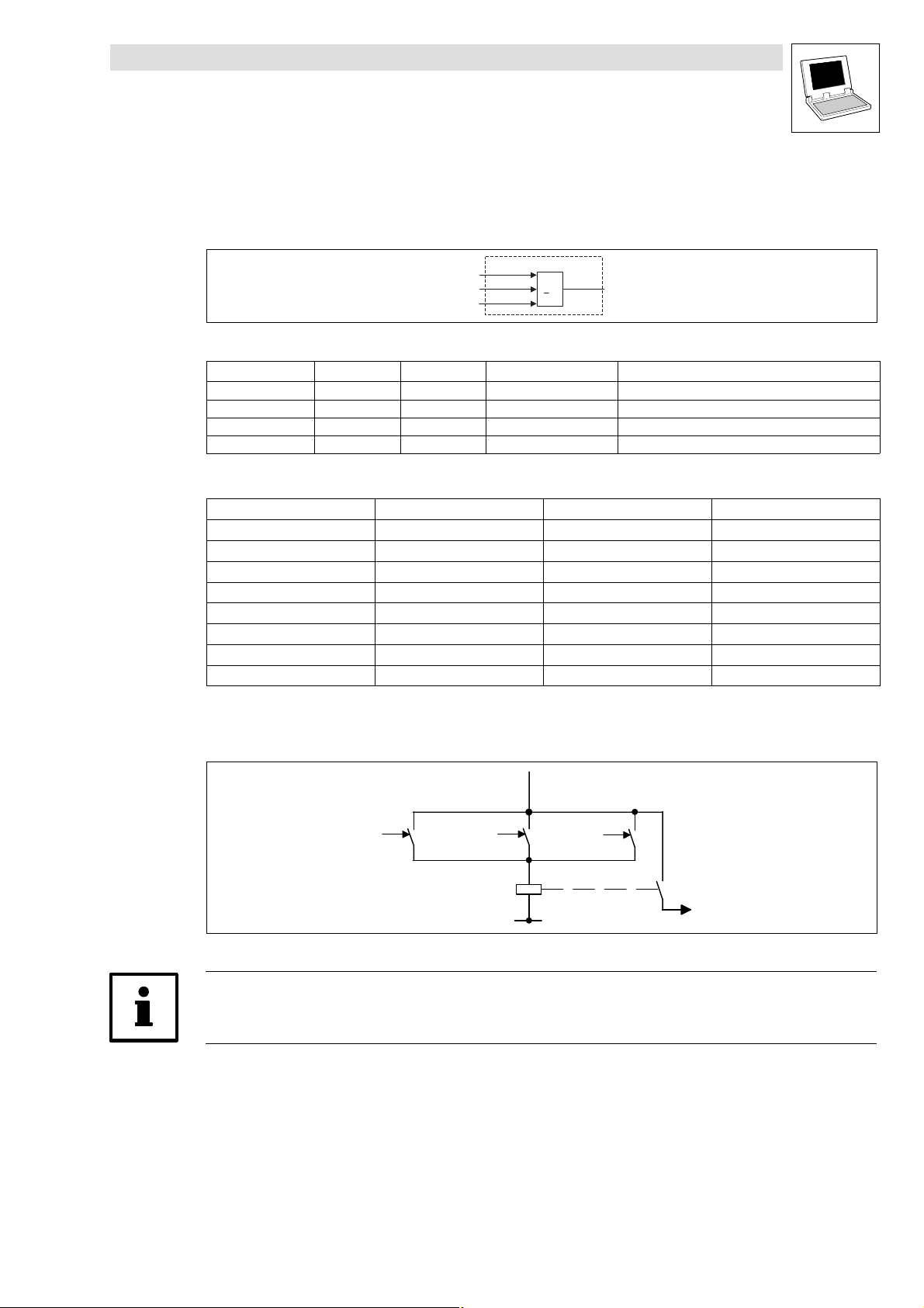
2.3.1 Logical AND (L_AND)
This FB implements the logical AND combination of binary signals. These operations can be used
for the control of functions or the generation of status information.
Fig. 2−32 Logical AND (L_AND)
VariableName DataType SignalType VariableType Note
bIn1_b Bool binary VAR_INPUT
bIn2_b Bool binary VAR_INPUT
bIn3_b Bool binary VAR_INPUT
bOut_b Bool binary VAR_OUTPUT
Truth table
bIn1_b bIn2_b bIn3_b bOut_b
0 0 0 0
1 0 0 0
0 1 0 0
1 1 0 0
0 0 1 0
1 0 1 0
0 1 1 0
1 1 1 1
0 = FALSE
1 = TRUE
The function corresponds to a series connection of normally−open contacts in a contactor control.
bIn1_b
bIn2_b
bIn3_b
&
L_AND
bOut_b
bIn1_b
bIn2_b
bIn3_b
Fig. 2−33 AND function as a series connection of normally−open contacts
Note!
Use the inputs bIn1_b and bIn2_b if you only need two inputs. Fix input bIn3_b to TRUE.
L
LenzeDrive.lib EN 1.7
bOut_b
2−29
Page 40

Function library LenzeDrive.lib
Digital signal processing
2.3.2 Delay (L_DIGDEL)
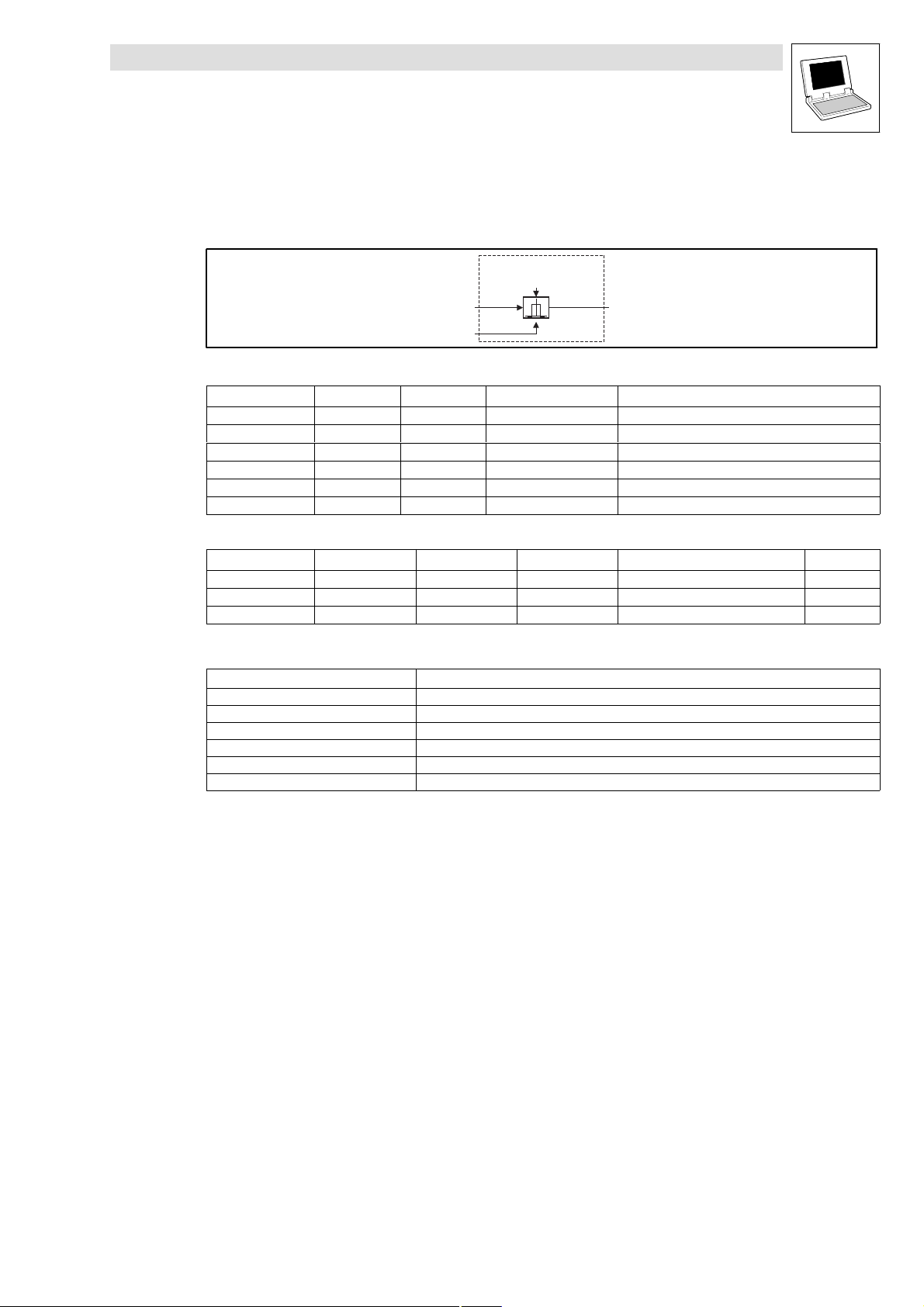
2.3.2 Delay (L_DIGDEL)
This FB delays binary signals.
Fig. 2−34 Delay element (L_DIGDEL)
VariableName DataType SignalType VariableType Note
bIn_b Bool binary VAR_INPUT
bOut_b Bool binary VAR_OUTPUT
byFunction Byte VAR CONSTANT RETAIN Selection of the function
wDelayTime Word VAR CONSTANT RETAIN Delay time
Parameter codes of the instances
VariableName L_DIGDEL1 L_DIGDEL2 SettingRange Lenze
byFunction
wDelayTime C0721 C0726 0.001 ... 60.000 s 1.000
C0720
L_DIGDEL
byFunction
wDelayTime
bIn_b
0t
C0725 0
bOut_b
0 ... 2
2
Range of functions
On−delay
Dropout delay
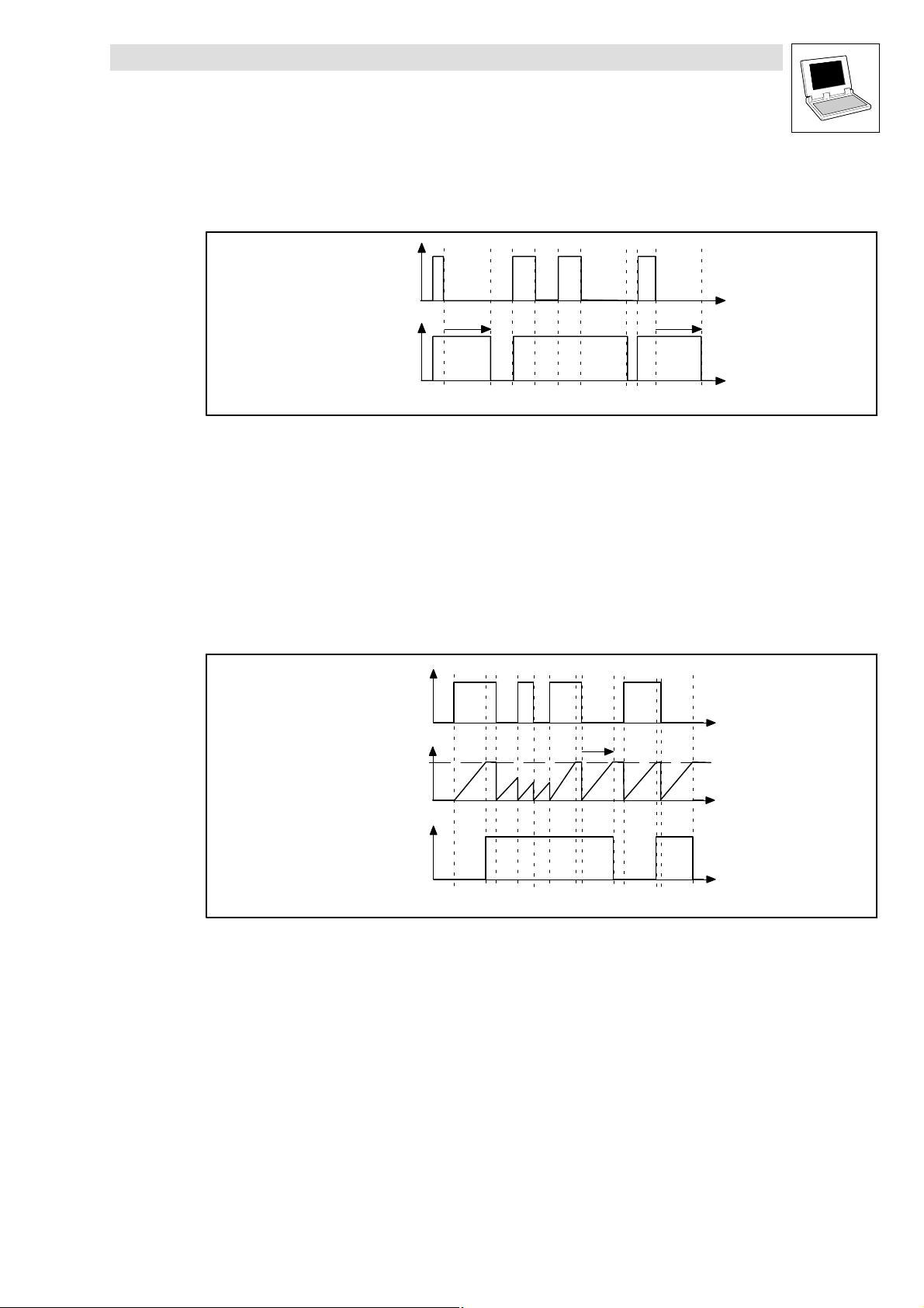
General delay
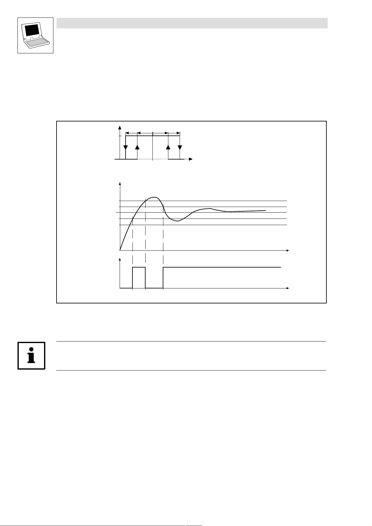
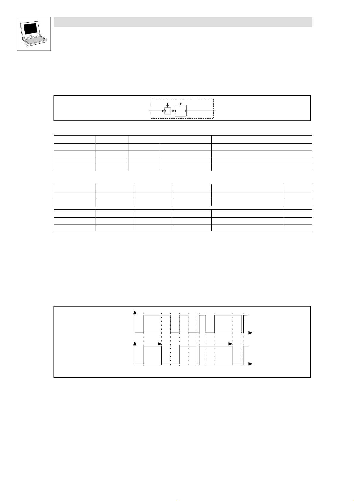
2.3.2.1 On−delay
byFunction = 0
Fig. 2−35 On−delay
The FB L_DIGDEL operates like a retriggerable monostable circuit.
bIn_b
bOut_b
wDelayTime
wDelayTime
t
t
2−30
Functional sequence
1. A FALSE−TRUE transition at nIn_b starts the timer element.
2. If the delay time has elapsed, that is set by wDelayTim has elapsed, bOut_b switches
immediately = TRUE.
3. A TRUE−FALSE edge at nIn_b resets the timer element, and switches bOut_b = FALSE,
immediately.
LenzeDrive.lib EN 1.7
L
Page 41
Function library LenzeDrive.lib
Digital signal processing
2.3.2 Delay (L_DIGDEL)
2.3.2.2 Dropout delay
byFunction = 1
bIn_b
Fig. 2−36 Dropout delay
Functional sequence
1. A FALSE−TRUE transition at nIn_b switches bOut_b = TRUE and resets the timer element.
2. A TRUE−FALSE edge at nIn_b starts the timer element.
3. If the delay time has elapsed, that is set by wDelayTime has elapsed, bOut_b = FALSE,
immediately.
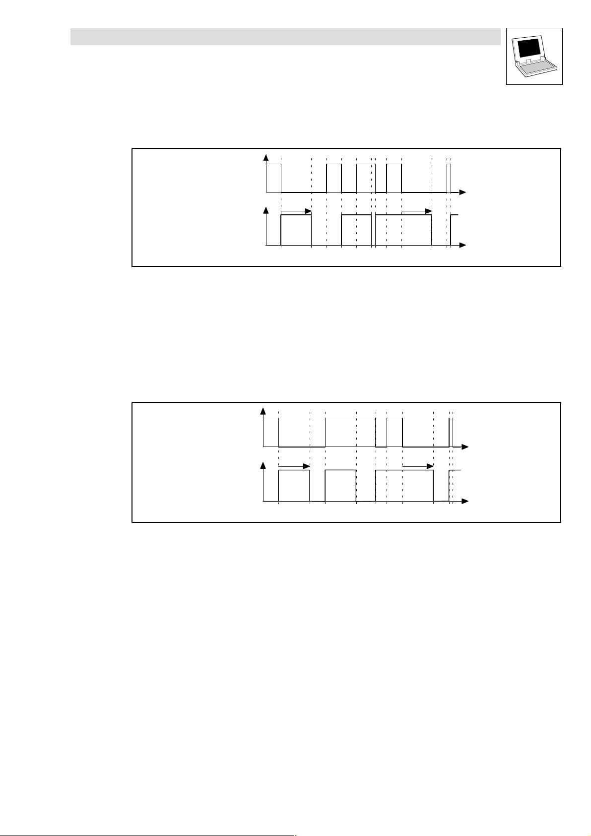
2.3.2.3 General delay
byFunction = 2
bOut_b
bIn_b
wDelayTime
wDelay
Time
wDelayTime
t
t
t
Fig. 2−37 General delay
Functional sequence
1. Any edge/transition at nIn_b resets the timer element, and starts it.
2. After the delay time, that is set by wDelayTime has elapsed, bOut_b = nIn_b.
L
bOut_b
LenzeDrive.lib EN 1.7
t
t
2−31
Page 42
Function library LenzeDrive.lib
Digital signal processing
2.3.3 Up/down counter (L_FCNT)
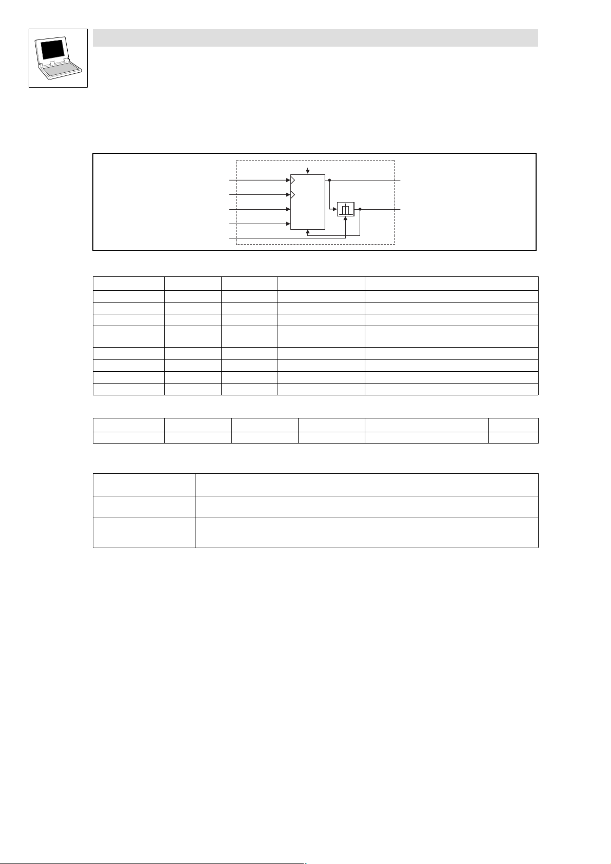
2.3.3 Up/down counter (L_FCNT)
This FB is a digital up/down counter, that is limited to the value nCmpVal_a.
Fig. 2−38 Up/down counter (L_FCNT)
VariableName DataType SignalType VariableType Note
bClkUp_b Bool binary VAR_INPUT FALSE−TRUE edge = counts up by 1.
bClkDwn_b Bool binary VAR_INPUT FALSE−TRUE edge = counts down by 1.
nLdVal_a Integer analog VAR_INPUT Start value
bLoad_b Bool binary VAR_INPUT TRUE = accept start value
nCmpVal_a Integer analog VAR_INPUT Comparison value
nOut_a Integer analog VAR_OUTPUT The count value is limited to ±32767.
bEqual_b Bool binary VAR_OUTPUT TRUE = comparison value reached.
byFunction Byte VAR CONSTANT RETAIN Selection of the function
Parameter codes of the instances
VariableName L_FCNT1 SettingRange Lenze
byFunction C1100 1 ... 2 1
Function
bClkUp_b
bClkDown_b
nLdVal_a
bLoad_b
nCmpVal_a
byFunction
CTRL
L_FCNT
nOut_a
bEqual_b
The input has the highest priority.
Selection of the
Function
byFunction = 1 If the count value nCmpVal_a , the output bEqual_b is set to TRUE. At the next clock cyle, the
byFunction = 2 If the count value = nCmpVal_a , the counter stops( bClkUp_b / bClkDwn_b are ignored).
Description
counter is reset to the value nLdVal_a and the output bEqual_b is set to FALSE.
bLoad_b = TRUE sets the counter to the value at nLdVal_a and responds to bClkUp_b / bClkDwn_b
again.
2−32
LenzeDrive.lib EN 1.7
L
Page 43

Function library LenzeDrive.lib
Digital signal processing
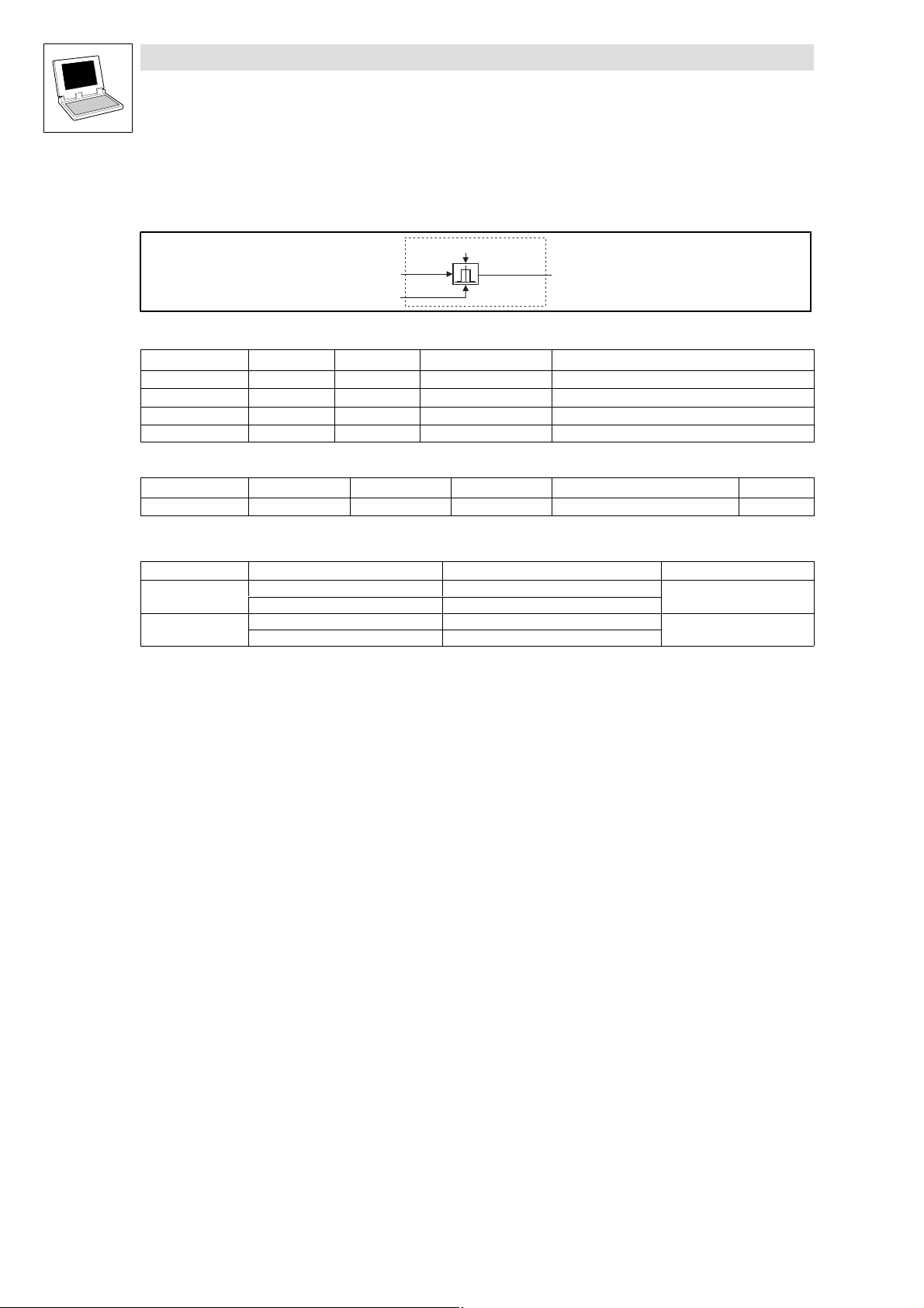
2.3.4 Flip−flop (L_FLIP)
2.3.4 Flip−flop (L_FLIP)
This FB is implemented as a D flip−flop. You can use this function to evaluate and store digital signal
transitions (edges).
Fig. 2−39 Flipflop (L_FLIP)
VariableName DataType SignalType VariableType Note
bD_b Bool binary VAR_INPUT
bClk_b Bool binary VAR_INPUT Evaluates FALSE−TRUE edges only
bClr_b Bool binary VAR_INPUT Evaluates the input level only; input has highest
bOut_b Bool binary VAR_OUTPUT
Functional sequence
bD_b
bClk_b
bOut_b
bD_b
bClk_b
bClr_b
D
CLR
Q
L_FLIP
bOut_b
(edge−triggered).
priority (reset input).
t
t
Fig. 2−40 Sequence of a flip−flop
bClr_b always has priority.
1. If bClr_b = TRUE, then bOut_b switches = FALSE. This state is held as long as bClr_b = TRUE.
2. A FALSE−TRUE edge at bClk_b switches bD_b = bOut_b. This state is stored until
– another FALSE−TRUE edge occurs at bClk_b or
– bClr_b switches = TRUE.
t
L
LenzeDrive.lib EN 1.7
2−33
Page 44

Function library LenzeDrive.lib
Digital signal processing
2.3.5 Logical NOT (L_NOT)
2.3.5 Logical NOT (L_NOT)
This FB enables the logical inversion of digital signals. You can use this FB for the control of functions
or the generation of status information.
Fig. 2−41 Logical NOT (L_NOT)
VariableName DataType SignalType VariableType Note
bIn_b Bool binary VAR_INPUT
bOut_b Bool binary VAR_OUTPUT
Truth table
0 = FALSE
1 = TRUE
The function corresponds to a change from a normally−open contact to a normally−closed contact
in a control with contactors.
bIn_b
bIn_b bOut_b
0 1
1 0
bIn_b
L_NOT
bOut_b
1
bOut_b
Fig. 2−42 Function of L_NOT as a change from a normally−open to a normally−closed contact
2−34
LenzeDrive.lib EN 1.7
L
Page 45
Function library LenzeDrive.lib
Digital signal processing
2.3.6 Logical OR (L_OR)
2.3.6 Logical OR (L_OR)
This FB enables the logical OR combination of digital signals. You can use this combination for the
control of functions or the generation of status information.
Fig. 2−43 Logical OR (L_OR
VariableName DataType SignalType VariableType Note
bIn1_b Bool binary VAR_INPUT
bIn2_b Bool binary VAR_INPUT
bIn3_b Bool binary VAR_INPUT
bOut_b Bool binary VAR_OUTPUT
Truth table
bIn1_b bIn2_b bIn3_b bOut_b
0 0 0 0
1 0 0 1
0 1 0 1
1 1 0 1
0 0 1 1
1 0 1 1
0 1 1 1
1 1 1 1
0 = FALSE
1 = TRUE
The function corresponds to a parallel connection of normally−open contacts in a contactor control.
bIn1_b
bIn2_b
bIn3_b
L_OR
bOut_b
>1
bIn1_b
Fig. 2−44 Function of L_OR as a parallel connection of normally−open contacts
bIn2_b
bIn3_b
Note!
If you only need 2 inputs, use the inputs bIn1_b and bIn2_b. Fix the input bIn3_b to FALSE.
L
LenzeDrive.lib EN 1.7
bOut_b
2−35
Page 46
Function library LenzeDrive.lib
Digital signal processing
2.3.7 Edge evaluation (L_TRANS)
2.3.7 Edge evaluation (L_TRANS)
This FB is a post−triggered edge detector. You can use this function to detect digital signal transitions
(edges) and turn them into defined pulses.
Fig. 2−45 Edge evaluation (L_TRANS)
VariableName DataType SignalType VariableType Note
bIn_b Bool binary VAR_INPUT
bOut_b Bool binary VAR_OUTPUT (retriggerable)
byFunction Byte − VAR CONSTANT RETAIN Selection of the function
wPulseTime Word − VAR CONSTANT RETAIN Pulse duration of the output signal
Parameter codes of the instances
VariableName L_TRANS1 L_TRANS2 L_TRANS3 SettingRange Lenze
byFunction C0710 C0715 C1140 0 ... 2 0
wPulseTime C0711 C0716 C1141 0.001 ... 60.000 s 0.001
bIn_b
byFunction
wPulseTime
0t
L_TRANS
bOut_b
VariableName L_TRANS4 SettingRange Lenze
byFunction C1145 0 ... 2 0
wPulseTime C1146 0.001 ... 60.000 s 0.001
Range of functions
Evaluate rising edges
Evaluate falling edges
Evaluate rising and falling edges
2.3.7.1 Evaluate rising edges
byFunction = 0
bIn_b
bOut_b
Fig. 2−46 Evaluation of FALSE−TRUE transitions
wPulseTime wPulseTime
t
t
2−36
Functional sequence
1. If a TRUE−FALSE or a FALS−TRUE transition occurs at nIn_b, then bOut_b switches = TRUE.
2. After the time defined as wPulseTime has elapsed, then bOut_b switches = FALSE, provided
no further FALSE−TRUE transition has occurred at nIn_b.
LenzeDrive.lib EN 1.7
L
Page 47
Function library LenzeDrive.lib
Digital signal processing
2.3.7 Edge evaluation (L_TRANS)
2.3.7.2 Evaluate falling edges
byFunction = 1
bIn−b
wPulseTime wPulseTime
bOut_b
Fig. 2−47 Evaluation of TRUE−FALSE transitions
Functional sequence
1. If a TRUE−FALSE or a FALSE−TRUE transition occurs at nIn_b, then bOut_b switches = TRUE.
2. After the time defined as wPulseTime has elapsed, then bOut_b switches = FALSE, provided
no further TRUE−FALSE transition has occurred at nIn_b.
2.3.7.3 Evaluate rising and falling edges
byFunction = 2
bIn_b
wPulsTime wPulsTime
bOut_b
t
t
t
Fig. 2−48 Evaluation of both transitions
Functional sequence
1. If a TRUE−FALSE or a FALS−TRUE transition occurs at nIn_b, then bOut_b switches = TRUE.
2. After the time defined as wPulseTime has elapsed, then bOut_b switches = FALSE, provided
no further TRUE−FALSE or FALSE−TRUE transition has occurred at nIn_b.
t
L
LenzeDrive.lib EN 1.7
2−37
Page 48

Function library LenzeDrive.lib
Processing of phase−angle signals
2.4.1 Arithmetic (L_ARITPH)
2.4 Processing of phase−angle signals
2.4.1 Arithmetic (L_ARITPH)
This FB calculates a phase output signal from two phase input signals.
Fig. 2−49 Arithmetic (L_ARITPH)
VariableName DataType SignalType VariableType Note
dnIn1_p Double Integer position VAR_INPUT
dnIn2_p Double Integer position VAR_INPUT
dnOut_p Double Integer position VAR_OUTPUT The signal is limited to ±230.
byFunction Byte VAR CONSTANT RETAIN Selection of the function
Parameter codes of the instances
VariableName L_ARITPH1 SettingRange Lenze
byFunction C1010 0 ... 3, 14, 21, 22 1
Function
Selection of the function Arithmetic function Limiting of the
byFunction = 0 dnOut_p = dnIn1_p without dnOut_p is not limited.
byFunction = 1 dnOut_p = dnIn1_p + dnIn2_p 2
byFunction = 2 dnOut_p = dnIn1_p − dnIn2_p 2
byFunction = 3 dnOut_p = (dnIn1_p dnIn2_p) / 2
byFunction = 14 dnOut_p = dnIn1_p / dnIn2_p 2
byFunction = 21 dnOut_p = dnIn1_p + dnIn2_p without with overflow
byFunction = 22 dnOut_p = dnIn1_p − dnIn2_p without with overflow
byFunction = 21/22:
Please note, that an overflow may occur, and then the numerical value of dnOut_p does not
match the result.
byFunction = 14:
If the denominator = 0, then dnOut_p = 230 The sign depends on the sign of dnIn1_p.
d n I n 1 _ p
d n I n 2 _ p
b y F u n c t i o n
x
y
L _ A R I T P H
3 0
± 2
+
*
-
/
d n O u t _ p
result
30
30
30
30
2
30
Note
(remainder not considered)
(remainder not considered)
2−38
LenzeDrive.lib EN 1.7
L
Page 49

Function library LenzeDrive.lib
Processing of phase−angle signals
2.4.2 Addition (L_PHADD)
2.4.2 Addition (L_PHADD)
This FB adds or subtracts phase signals, depending on the input that is used.
3 1
L _ P H A D D
Fig. 2−50 Addition (L_PHADD)
VariableName DataType SignalType VariableType Note
dnIn1_p Double−integer position VAR_INPUT Addition input
dnIn2_p Double−integer position VAR_INPUT Addition input
dnIn3_p Double−integer position VAR_INPUT Subtraction input
dnOut_p Double−integer position VAR_OUTPUT The signal is limited to ±2147483647
dnOut2_p Double−integer position VAR_OUTPUT Signal without limiting / with overflow
Functional sequence
d n I n 1 _ p
d n I n 2 _ p
d n I n 3 _ p
+
-
+
± 2 - 1
d n O u t _ p
d n O u t 2 _ p
1. The signal at dnIn1_p is added to the signal at dnIn2_p
2. The signal at dnIn3_p is subtracted from the calculated result.
3. The result of the subtraction is then limited to ±2147483647 and output to dnOut_p and output
as unlimited to dnOut2_p.
Please observe, that at dnOut2_p there may be an overflow, thus producing a false value.
L
LenzeDrive.lib EN 1.7
2−39
Page 50
Function library LenzeDrive.lib
Processing of phase−angle signals
2.4.3 Comparison (L_PHCMP)
2.4.3 Comparison (L_PHCMP)
This FB compares two phase signals (paths) with each other.
Fig. 2−51 Comparison (L_PHCMP)
VariableName DataType SignalType VariableType Note
dnIn1_p Double−integer position VAR_INPUT Signal to be compared
dnIn2_p Double−integer position VAR_INPUT Comparison value
bOut_b Bool binary VAR_OUTPUT
byFunction Byte VAR CONSTANT RETAIN Selection of the function
Parameter codes of the instances
VariableName L_PHCMP1 L_PHCMP2 L_PHCMP3 SettingRange Lenze
byFunction C0695 C1207 C1272 1 ... 2 2
Function
Selection Comparison function If the comparison condition is fulfilled Note
byFunction = 1
byFunction = 2
dnIn1_p < dnIn2_p bOut_b = HIGH
dnIn1_p dnIn2_p bOut_b = LOW
dnIn1_p<dnIn2_p bOut_b = HIGH
dnIn1_pdnIn2_p bOut_b = LOW
dnIn1_p
dnIn2_p
byFunction
L_PHCMP
bOut_b
Compares the absolute value
of the inputs.
2−40
LenzeDrive.lib EN 1.7
L
Page 51

Function library LenzeDrive.lib
Processing of phase−angle signals
2.4.4 Difference (L_PHDIFF)
2.4.4 Difference (L_PHDIFF)
This FB adds a phase−angle signal to the phase setpoint. A setpoint/actual value comparison is also
possible.
L _ P H D I F F
d n O u t _ p
+
-
Fig. 2−52 Difference (L_PHDIFF)
d n S e t _ p
d n A d d _ p
b E n _ b
n I n _ v
b R e s e t _ b
I n t e r v a l T i m e
T A S K
VariableName
dnSet_p Double−integer position VAR_INPUT Provision of a position setpoint
dnAdd_p Double−integer position VAR_INPUT Adaptive position value for an actual position
bEn_b Bool binary VAR_INPUT TRUE = Adaptive position value is added on.
nIn_v Integer velocity VAR_INPUT Provision of the actual speed for conversion/calculation
bReset_b Bool binary VAR_INPUT TRUE = Actual phase−angle integrator is set to 0.
dnOut_p Double−integer position VAR_OUTPUT Signal is not limited.
DataType SignalType VariableType Note
of the position value
Functional sequence
If bEn_b = TRUE :
1. The speed (rpm) signal at nIn_v is integrated by the phase−angle integrator.
2. The phase−angle signal at dnAdd_p is added to the integrated speed signal in each task cycle.
3. The result of the phase−angle integrator is subtracted from the phase−angle signal at dnSet_p
and then output at dnOut_p.
If bEn_b = FALSE
1. The speed (rpm) signal at nIn_v is integrated by the phase−angle integrator.
2. The result of the phase−angle integrator is subtracted from the phase−angle signal at dnSet_p
and then output at dnOut_p.
Note!
The phase−angle integrator derives a position from a speed.
In nIn_v the speed can be defined (16384 15000 rpm ).
(INT)65536 corresponds to one encoder turn.
L
LenzeDrive.lib EN 1.7
2−41
Page 52

Function library LenzeDrive.lib
Processing of phase−angle signals
2.4.5 Division (L_PHDIV)
2.4.5 Division (L_PHDIV)
This FB divides or multiplies phase−angle signals in binary−exponent format.
Fig. 2−53 Division (L_PHDIV)
VariableName DataType SignalType VariableType Note
dnIn_p Double integer position VAR_INPUT
dnOut_p Double integer position VAR_OUTPUT 65536 inc = 1 encoder revlution
byDivision Short Integer VAR CONSTANT RETAIN Exponent of the divisor
Parameter codes of the instances
VariableName L_PHDIV1 SettingRange Lenze
byDivision C0995 −31 ... 31 0
Function
d n I n _ p
2
1
b y D iv i s i o n
± 2
R e v o lu ti o n
3 1
L _ P H D I V
d n O u t _ p
You can calculate the result of the arithmetical function according to the formula:
dnOut_p +
dnIn_p
byDivision
2
Positive values in byDivision result in a division.
Negative values in byDivision result in a multiplication.
The output signal is limited to ±2
– The output signal cannot exceed this limit value.
31
−1 encoder turns.
2−42
LenzeDrive.lib EN 1.7
L
Page 53

Function library LenzeDrive.lib
t
Processing of phase−angle signals
2.4.6 Integration (L_PHINT)
2.4.6 Integration (L_PHINT)
This FB can integrate a speed or a velocity to a phase−angle (path/distance). The integrator can
accept max. ±32000 encoder revolutions.
L _ P H I N T
± 3 2 0 0 0
R e v o lu ti o n
d n O u t _ p
b F a i l _ b
bFail_b = FALSE .
Fig. 2−54 Integration (L_PHINT)
VariableName DataType SignalType VariableType Note
nIn_v Integer velocity VAR_INPUT Actual speed value: 16384 15000 rpm
bReset_b Bool binary VAR_INPUT TRUE sets the phase−angle integrator = 0 and
dnOut_p Double−integer position VAR_OUTPUT 65536 inc = 1 encoder revolution (Overflow is possible.)
bFail_b Bool binary VAR_OUTPUT TRUE = Overflow occurred.
Range of functions
I n t e r v a l T i m e
T A S K
n I n _ v
b R e s e t _ b
Constant input value
Calculation of the output signal
2.4.6.1 Constant input value
Fig. 2−55 Function of L_PHINT with constant input value
A positive signal at nIn_v is incremented (the counter value is increased at every call of the
function).
dnOut_p
+32767 revolutions
+32000 revolutions
t
-32000 revolutions
-32767 revolutions
bFail_b
L
A negative signal at nIn_v is decremented (the counter value is decreased at every call of the
function).
dnOut_p produces the count value of the bipolar integrator.
If the count exceeds the value of +32000 encoder revolutions, then
bFail_b switches = TRUE.
If the count exceeds the value of +32767 encoder revolutions (corresponds to +2147483647
inc.) there is an overflow, and the count procedure continues from a value of −32768 encoder
turns.
LenzeDrive.lib EN 1.7
2−43
Page 54

Function library LenzeDrive.lib
Processing of phase−angle signals
2.4.6 Integration (L_PHINT)
If the count falls below the value of −32000 encoder revolutions, then
bFail_b switches= TRUE.
If the count falls below the value of −32768 encoder revolutions (corresponds to −2147483648
inc.) there is an overflow, and the count procedure continues from a value of +32767 encoder
turns.
bReset_b = TRUE:
– the integrator switches to 0.
– sets dnOut_p to 0, as long as nIn_v has a positive signal applied.
– switches bFail_b = FALSE .
2.4.6.2 Calculation of the output signal
The output value at dnOut_p can be derived from the formula:
dnOut_p[inc] + nIn_v[rpm] @ t[s] @ 65536[incńUmdr.]
(t = integration time, 16384 15000 rpm, 1 inc. = 1)
Example:
You want to determine the count of the integrator with a certain speed at the input and a certain
integration time t.
Given values:
– nIn_v = 1000 rpm (INT)1092
– t = 10 s
– Start value of the integrator is 0.
Solution:
– Conversion of the input signal nIn_v:
1000rpm +
– Calculation of the output signal
dnOut_p +
1000rev.
60s
1000rev.
60s
@ 10s @
65536inc
rev.
+ 10922666inc
2−44
LenzeDrive.lib EN 1.7
L
Page 55

Function library LenzeDrive.lib
Processing of phase−angle signals
2.4.7 Integration (L_PHINTK)
2.4.7 Integration (L_PHINTK)
This FB can integrate a speed or a velocity to a phase−angle (path/distance). It can also recognize
a relative distance. The integrator can accept max. ±32000 encoder revolutions.
b y M o d e
d n C m p
L _ P H I N T K
d n O u t _ p
b S t a t u s _ b
nIn_v and bStatus_b = FALSE .
Fig. 2−56 Integration (L_PHINTK)
VariableName DataType SignalType VariableType Note
nIn_v Integer velocity VAR_INPUT Actual speed value: 16384 15000 rpm
bLoad_b Bool binary VAR_INPUT = TRUE sets the phase−angle integrator to the signal at
dnSet_p Double−integer position VAR_INPUT
dnOut_p Double−integer position VAR_OUTPUT 65536 inc = 1 encoder revolution (Overflow is possible.)
bStatus_b Bool binary VAR_OUTPUT TRUE = Overflow occurred or distance processed.
byMode Byte VAR CONSTANT RETAIN Selection of the function
dnCmp Double−integer VAR CONSTANT RETAIN Comparison value
Parameter codes of the instances
I n t e r v a l T i m e
n I n _ v
b L o a d _ b
d n S e t _ p
T A S K
VariableName L_PHINTK1 SettingRange Lenze
byMode C1150 0 ... 2 0
dnCmp C1151 0 ... 2000000000 2000000000
Range of functions
Constant input value
Input value with change of sign
Calculation of the output signal
L
LenzeDrive.lib EN 1.7
2−45
Page 56

Function library LenzeDrive.lib
t
Processing of phase−angle signals
2.4.7 Integration (L_PHINTK)
2.4.7.1 Constant input value
3 functions are available, that you can select with byMode.
byMode = 0
The input bLoad_b is level−triggered (TRUE−level).
bLoad_b = TRUE
– The integrator is loaded with the value at dnSet_p.
– The FB switches bStatus_b = FALSE.
byMode = 1
The input bLoad_b is edge−triggered (FALSE−TRUE transition).
bLoad_b = FALSE−TRUE edge/transition
– The integrator is loaded with the value at dnSet_p and immediately integrated from then on.
– The FB switches bStatus_b= FALSE.
dnOut_p
+32767 revolutions
Fig. 2−57 Function of L_PHINTK with constant input value
(+) Variable with positive value
(−) Variable with negative value
A positive value at nIn_v is incremented
(the counter value is increased at every call of the function).
A negative value at nIn_v is decremented
(the counter value is decreased at every call of the function).
dnOut_p produces the count value of the bipolar integrator.
If the count exceeds the value of +32767 encoder revolutions (corresponds to
+2147483647 inc):
– There is an overflow, and counting continues at the value −32768 encoder turns.
– Switches bStatus_b = TRUE, when a positive preset value is reached at dnCmp.
If the count falls below the value of −32768 encoder revolutions (corresponds to
−2147483648 inc):
– There is an overflow, and counting continues at the value +32767 encoder turns.
– Switches bStatus_b = TRUE, when a negative preset value is reached at dnCmp.
(+) dnCmp
t
(-) dnCmp
-32767 revolutions
bStatus_b
2−46
LenzeDrive.lib EN 1.7
L
Page 57

Function library LenzeDrive.lib
Processing of phase−angle signals
2.4.7 Integration (L_PHINTK)
2.4.7.2 Input value with change of sign
byMode = 2
The input bLoad_b is level−triggered (TRUE−level).
bLoad_b = TRUE
– The integrator is loaded with the value at dnSet_p.
– The FB switches bStatus_b = FALSE.
dnOut_p
(+) dnCmp
t
(-) dnCmp
bStatus_b
Fig. 2−58 Function of L_PHINTK with change of sign for the input value
(+) Variable with positive value
(−) Variable with negative value
Change of sign for the value at nIn_v
A positive value at nIn_v is incremented (the counter value is increased at every call of the
function).
A negative value at nIn_v is decremented (the counter value is decreased at every call of the
function).
dnOut_p produces the count value of the bipolar integrator.
If the count value exceeds a preset positive value at dnCmp:
– The count value is reduced by the value of dnCmp.
– Switches bStatus_b = TRUE for the time of one cycle.
If the count value goes below a preset negative value in dnCmp:
– The count value is increased by the value of dnCmp.
– Switches bStatus_b = TRUE for the time of one cycle.
t
L
LenzeDrive.lib EN 1.7
2−47
Page 58

Function library LenzeDrive.lib
Processing of phase−angle signals
2.4.7 Integration (L_PHINTK)
2.4.7.3 Calculation of the output signal
The output value at dnOut_p can be derived from the formula:
dnOut_p[inc] + nIn_v[rpm] @ t[s] @ 65536[incńrev.]
(t = integration time, 16384 15000 rpm, 1 incr. = 1)
Example:
You want to determine the count of the integrator with a certain speed at the input and a certain
integration time t.
Given values:
– nIn_v = 1000 rpm (INT)1092
– t = 10 s
– Start value of the integrator is 0.
Solution:
– Conversion of the input signal at nIn_v:
1000rpm +
– Calculation of the output signal
dnOut_p +
1000rev.
60s
1000rev.
60s
@ 10s @
65536inc
rev.
+ 10922666inc
2−48
LenzeDrive.lib EN 1.7
L
Page 59

Function library LenzeDrive.lib
Signal conversion
2.5.1 Normalization (L_CONV)
2.5 Signal conversion
2.5.1 Normalization (L_CONV)
This FB normalizes signals. The calculation is made quite precisely, with remainder processing and
definition of the conversion factor as a numerator and denominator.
Fig. 2−59 Normalization (L_CONV)
VariableName DataType SignalType VariableType Note
nIn_a Integer analog VAR_INPUT 100 % 16384 C0011 (n
nOut_a Integer analog VAR_OUTPUT The signal it limited to ±199.99 % (100 % 16384).
nNumerator Integer VAR CONSTANT RETAIN Numerator
nDenominator Integer VAR CONSTANT RETAIN Denominator
Parameter codes of the instances
VariableName L_CONV1 L_CONV2 L_CONV3 SettingRange Lenze
nNumerator C0940 C0945 C0950 −32767 ... 32767 1
nDenominator C0941 C0946 C0951 1 ... 32767 1
VariableName L_CONV4 L_CONV5 L_CONV6 SettingRange Lenze
nNumerator C0955 C0655 C1170 −32767 ... 32767 1
nDenominator C0956 C0656 C1171 1 ... 32767 1
Function
The multiplication or division of signals is made according to the formula:
nOut + nIn @
nNumerator
nDenominator
n I n _ a
n N u m e r a t o r
n D e n o m i n a t o r
L _ C O N V
n O u t _ a
max
)
L
LenzeDrive.lib EN 1.7
2−49
Page 60
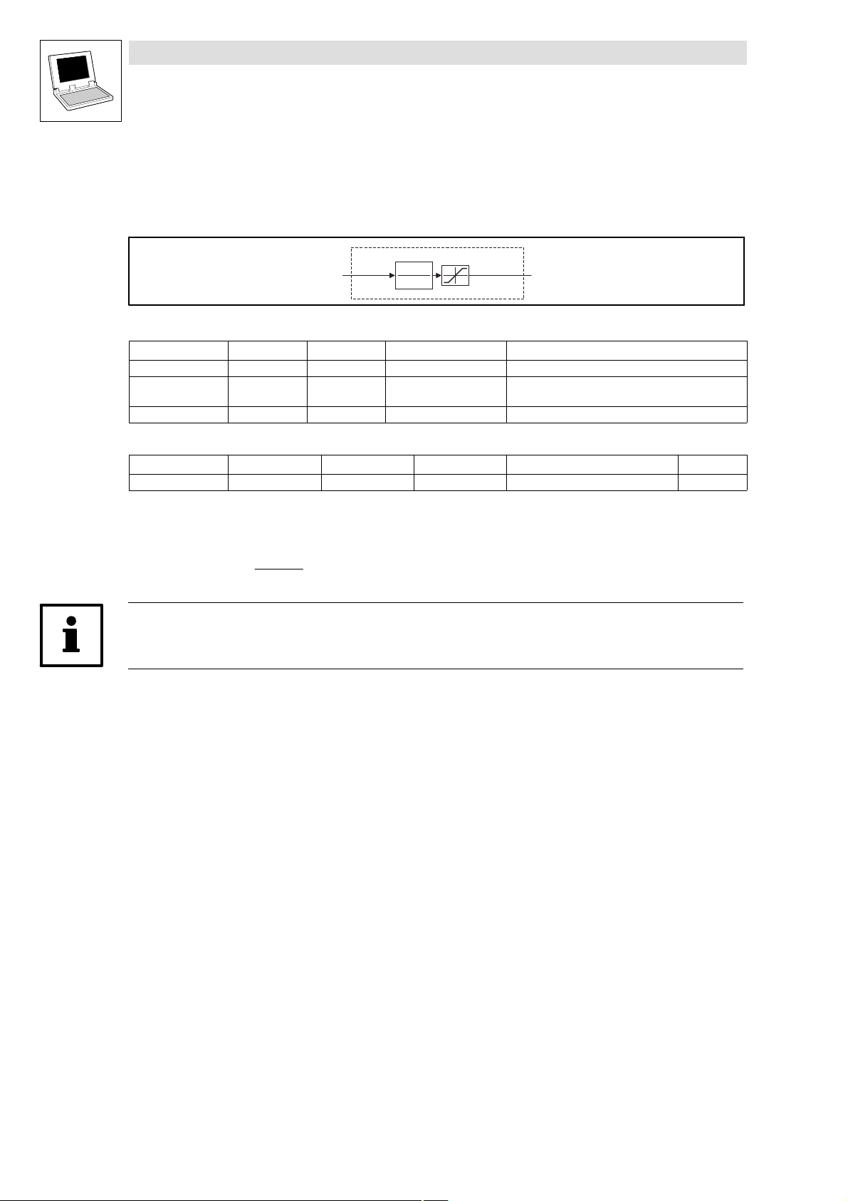
Function library LenzeDrive.lib
Signal conversion
2.5.2 Conversion of phase−angle to analog (L_CONVPA)
2.5.2 Conversion of phase−angle to analog (L_CONVPA)
This FB converts a phase−angle signal into an integer signal.
This function corresponds to the function of the FB CONVPHA in the 9300 servo inverter.
L _ C O N V P A
d n I n _ p
Fig. 2−60 Conversion of phase−angle to analog (L_CONVPA)
VariableName DataType SignalType VariableType Note
dnIn_p Double Integer position VAR_INPUT
nOut Integer analog VAR_OUTPUT The signal is limited to ±32767.
byDivision Byte VAR CONSTANT RETAIN Division factor
Parameter codes of the instances
VariableName L_CONVPA1 SettingRange Lenze
byDivision C1000 0 ... 31 1
2
1
b y D iv i s i o n
± 3 2 7 6 7
n O u t
Remainder handling
Function
The conversion is made according to the formula:
nOut_a + dnIn_p @
byDivision
2
1
Note!
This FB operates with remainder handling.
2−50
LenzeDrive.lib EN 1.7
L
Page 61
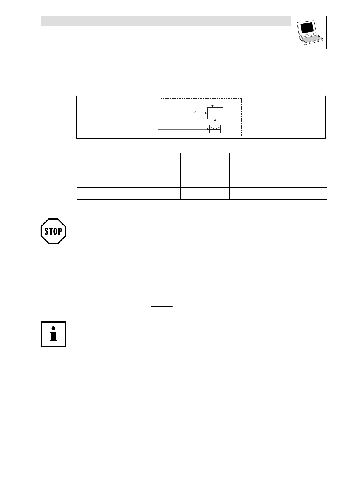
Function library LenzeDrive.lib
Signal conversion
2.5.3 Conversion of a phase−angle signal (L_CONVPP)
2.5.3 Conversion of a phase−angle signal (L_CONVPP)
This FB converts a phase signal with a dynamic fraction.
This function corresponds to the function of the FB CONVPHPH in the 9300 servo inverter.
nNum_a
dnIn_p
bAct_b
nDen_a
Fig. 2−61 Conversion of a phase−angle signal (L_CONVPP)
VariableName DataType SignalType VariableType Note
nNum_a Integer analog VAR_INPUT Numerator
dnIn_p Double Integer position VAR_INPUT
bAct_b Bool binary VAR_INPUT
nDen_a Integer analog VAR_INPUT Denominator (with absolute value generation)
dnOut_p Double Integer position VAR_OUTPUT The signal is not limited.
Function
STOP!
The conversion result is not limited. The result must therefore not exceed the range of ±2147483647.
The conversion is made according to the formula:
With bAct_b = TRUE
L_CONVPP
x
y
1
dnOut_p
Remainder handling
dnOut_p + dnIn_p @
nNum_a
nDen_a
With bAct_b = FALSE
dnOut_p + Remainder @
nNum_a
nDen_a
Tip!
This FB operates with remainder handling.
The denominator can only be 1.
(INT)65536 corresponds to one encoder turn (one encoder turn corresponds to
65536 increments).
L
LenzeDrive.lib EN 1.7
2−51
Page 62

Function library LenzeDrive.lib
Signal conversion
2.5.4 Conversion (L_CONVVV)
2.5.4 Conversion (L_CONVVV)
This FB converts a phase signal with a dynamic fraction.
This function corresponds to the function of the FB CONVPP in the 9300 servo inverter.
Fig. 2−62 Conversion (L_CONVVV)
VariableName DataType SignalType VariableType Note
dnNum_p Double Integer position VAR_INPUT Numerator
nIn_v Integer analog/velocity VAR_INPUT
dnDen_p Double Integer position VAR_INPUT Denominator (with absolute value generation)
nOut_v Integer analog/velocity VAR_OUTPUT The signal is not limited.
Function
Stop!
The conversion result is not limited. The result must therefore not exceed the range of ±32767.
The conversion is made according to the formula:
nOut_v + nIn_v @
dnNum_p
dnDen_p
d n N u m _ p
n I n _ v
d n D e n _ p
x
y
1
L _ C O N V V V
n O u t _ v
Remainder handling
Note!
This FB operates with remainder handling.
The denominator can only be 1.
16384 15000 rpm.
2−52
LenzeDrive.lib EN 1.7
L
Page 63

Function library LenzeDrive.lib
Signal conversion
2.5.5 Normalization with limiting (L_CONVX)
2.5.5 Normalization with limiting (L_CONVX)
This FB normalizes signals. The calculation is made with high−precision and remainder handling,
using the conversion factor for numerator and denominator.
L_CONVX
nIn
nNum
nDenom
bInvers_b
Fig. 2−63 Conversion (L_CONVX)
a
*
b
ab
1
±32767
nOut
0
1
VariableName
nIn Integer analog/velocity VAR_INPUT
nNum Integer analog/velocity VAR_INPUT Counter
nDenom Integer analog/velocity VAR_INPUT Denominator
bInvers_b Bool binary VAR_INPUT
nOut Integer analog/velocity VAR_OUTPUT
DataType SignalType VariableType Note
Function
The multiplication or division of signals is made according to the formula:
nOut + nIn @
dnNum
dnDenom
|
@ sgn |bInvers
|
|
Division by zero is prevented: if nDenom = 0 the the value of nDenom is set to 1.
The input value is calculated for nDenominator.
bInvers_b = TRUE means that the sign is reversed for the output variable nOut.
The calculation is made using remainder handling.
L
LenzeDrive.lib EN 1.7
2−53
Page 64

Function library LenzeDrive.lib
Communication
2.6.1 Type conversion (L_ByteArrayToDint)
2.6 Communication
2.6.1 Type conversion (L_ByteArrayToDint)
This FB converts a 4−byte array into a variable of type DINT.
VariableName DataType SignalType VariableType Note
abyIn Byte [0 ... 3] VAR_INPUT
dnOut Double−integer VAR_OUTPUT
2.6.2 Type conversion (L_DintToByteArray)
This FB converts a variable of type DINT into a 4−byte array, as, for instance, the FB L_ParWrite
expects for the input abyData.
VariableName DataType SignalType VariableType Note
dnIn Double−integer VAR_INPUT
abyOut Byte [0 ... 3] VAR_OUTPUT
2.6.3 Code index (L_FUNCodeIndexConv)
This function checks the value range 1 ... 8000 of a code index and transmits the index to, e. g. the
FB L_ParWrite via the wIndex input. If the code numbers are invalid, the function transmits the
0000 index.
2−54
VariableName DataType SignalType VariableType Note
wCodenumber Word VAR_INPUT
LenzeDrive.lib EN 1.7
L
Page 65

Function library LenzeDrive.lib
Communication
2.6.4 Read codes (L_ParRead)
2.6.4 Read codes (L_ParRead)
This FB is used to read parameters, with Lenze so−called codes. The FB can read both the PLC codes
and codes of other devices via the system bus (CAN).
L_ParRead
bExecute
wIndex
bySubIndex
byFraction
byComChannel
wTargetAddress
VariableName DataType VariableType Note
wTimeOut Word VAR CONSTANT
RETAIN
bExecute Bool VAR_INPUT FALSE/TRUE transition activates a read request.
wIndex Word VAR_INPUT 0 ... 65535 Code index
bySubIndex Byte VAR_INPUT 0 ... 255 Subindex (subcode number) of the code
byFraction Byte VAR_INPUT 0 ... 254 Number of decimal places of the code to be read
byComChannel Byte VAR_INPUT 0
wTargetAddress Word VAR_INPUT Selecting the parameter data channel of the target device
bDone Bool VAR_OUTPUT TRUE Order has been processed (observe bFail).
bBusy Bool VAR_OUTPUT TRUE Order is being processed.
bFail Bool VAR_OUTPUT TRUE Error occurred.
wFailNumber Word VAR_OUTPUT 0 OK − read request was executed without error.
abyData Byte [0 ... 3] VAR_OUTPUT The four data bytes with the read code value.
1 ... 65335 Time−out time in ms is the time for processing the order.
255 Code without decimal places
Constant:
10
Constant:
1 ... 64 Data transfer via SDO1 of the target device:
65 ... 127 Data transfer via SDO2 of the target device:
1 Error during data transfer via system bus (CAN).
2 External device did not respond within the set time−out time.
4 Subindex does not exist.
5 Index does not exist.
13 Parameter value to be read is not within the valid range.
117 Invalid communication channel (byComChannel).
118 There are not enough free CAN objects available.
119 The Send Order memory is full.
bDone
bBusy
bFail
wFailNumber
abyData
Initialized with 1000 ms.
This variable can be parameterized by means of a user
code.
Conversion formula: Index = 24575 − code number
(e.g. hexadecimal code).
Reading a PLC code.
C_PLC
Reading a code from a device connected via the system bus
(CAN).
C_SYSTEMBUS_CAN
(only with byComChannel = 10)
wTargetAddress = CAN device address of the target device
wTargetAddress = CAN device address of the target device +
64
L
LenzeDrive.lib EN 1.7
2−55
Page 66

Function library LenzeDrive.lib
Communication
2.6.4 Read codes (L_ParRead)
Note!
The FB L_ParRead must be cyclically called to ensure that the read response is received. Due to the
cycle time of the receiver, it may happen that the PLC receives the read response only after a few
program cycles.
If the FB is not cyclically called (e.g. in an event−controlled task) the FB might "get stuck" as a result.
Selection of the transmission channel
The transmission channel is selected under code C2118:
Code LCD
C2118 0 0 PDO channel (CAN1_IO ... CAN3_IO) Data is transferred via a free PDO
Possible settings
Lenze Selection
1 SDO2 channel Data is transferred via the SDO2
Info
channel of the PLC.
For the selection you need:
A free CAN transmitter
(CAN1_OUT ... CAN3_OUT) to
transmit the read request.
A free CAN receiver (CAN1_IN ...
CAN3_IN) to receive the read
response from the other device.
channel of the PLC.
Selection of the bus participant and the parameter data channel for the bus participant
The bus participant whose codes are to be accessed is selected under wTargetAddress. The
parameter data channel (SOD1 or SDO2) to be used for the bus participant is also selected under
wTargetAddress:
For data transfer via parameter data channel SDO1 enter the corresponding CAN device
address (1 ... 64) of the bus participant under wTargetAddress.
For data transfer via parameter data channel SDO2 enter the corresponding CAN device
address (1 ... 64) of the bus participant incremented by 64, i.e. a value between 65 and 127
under wTargetAddress.
2−56
PLC
L
wTargetAddress = 2
wTargetAddress = 2 + 64=66
Node-ID1
Target device
L
SDO1
SDO2
Node-ID2
Note!
Please ensure that the bus participant is not at the same time accessed by other bus participants
via the same parameter data channel since the system bus changes to the state "bus off" if a
"collision" occurs.
LenzeDrive.lib EN 1.7
L
Page 67

Function library LenzeDrive.lib
Communication
2.6.4 Read codes (L_ParRead)
Tip!
General information about the CAN objects and the system bus (CAN) can be found in the Manual
"System bus (CAN) for PLC devices".
Example
Read value of code C0011 of the device with CAN device address 2:
Tip!
For converting the code number into the value required for wIndex you can use the function
L_FUNCodeIndexConv (see example).
If you want to process the read value in DINT format you can use the FB L_DintToByteArray to
convert the 4−byte array abyData into a DINT value (see example).
L
LenzeDrive.lib EN 1.7
2−57
Page 68

Function library LenzeDrive.lib
Communication
2.6.4 Read codes (L_ParRead)
Parameter values with decimal places
Tip!
The parameters of the Lenze controllers are stored in different formats.
Detailed information about this can be found in the "Table of attributes" in the corresponding drive
controller Manual.
If the code to be read uses a data format with decimal places the number of decimal places has to
be communicated to the function block L_ParRead via the input byFraction.
The following formats apply:
byFraction (number of decimal places) Value output by FB L_ParRead Read code value
0 1 1
1 10 1.0
2 100 1.00
3 1000 1.000
4 10000 1.0000
Example:
Reading a code with the value "43" in fixed32 data format.
Fixed32 is a fixed−point format with 4 decimal places. For data transfer the value therefore has
to be multiplied by 10000:
Data
+ 43 @ 10000 + 430000 + 00 06 8F B0
1...4
hex
Select the value "4" at the input byFraction.
The FB L_ParRead outputs the value "430000".
Tip!
If the code does not use the fixed−point format the value "255" has to be selected at the input
byFraction.
Detailed information about reading and writing parameters via the system bus (CAN) can be found
in the Manual "System bus (CAN) for PLC devices".
2−58
LenzeDrive.lib EN 1.7
L
Page 69

Function library LenzeDrive.lib
Communication
2.6.5 Write codes (L_ParWrite)
2.6.5 Write codes (L_ParWrite)
This FB is used to write parameters, with Lenze so−called codes. The FB can write both the PLC
codes and codes of other devices via the system bus (CAN).
L_ParWrite
bExecute
wIndex
bySubIndex
abyData
byFraction
byComChannel
wTargetAddress
VariableName DataType VariableType Note
wTimeOut Word VAR CONSTANT
RETAIN
bExecute Bool VAR_INPUT FALSE/TRUE transition activates a write request.
wIndex Word VAR_INPUT 0 ... 65535 Code index
bySubIndex Byte VAR_INPUT 0 ... 255 Subindex (subcode number) of the code
abyData Byte [0 ... 3] VAR_INPUT The four data bytes with the code value to be written.
byFraction Byte VAR_INPUT 0 ... 254 Number of decimal places of the code to be written.
byComChannel Byte VAR_INPUT 0
wTargetAddress Word VAR_INPUT Selecting the parameter data channel of the target device
bDone Bool VAR_OUTPUT TRUE Order has been processed (observe bFail ).
bBusy Bool VAR_OUTPUT TRUE Order is being processed.
bFail Bool VAR_OUTPUT TRUE Error occurred.
1 ... 65335 Time−out time in ms is the time for processing the order.
255 Code without decimal places
Constant:
10
Constant:
1 ... 64 Data transfer via SDO1 of the target device:
65 ... 127 Data transfer via SDO2 of the target device:
bDone
bBusy
bFail
wFailNumber
Initialized with 1000 ms.
This variable can be parameterized by means of a user
code.
Conversion formula: Index = 24575 − code number
(e.g. hexadecimal code).
Writing a PLC code.
C_PLC
Writing a code in a device connected via the system bus (CAN).
C_SYSTEMBUS_CAN
(only with byComChannel = 10)
wTargetAddress = CAN device address of the target device
wTargetAddress = CAN device address of the target device +
64
L
LenzeDrive.lib EN 1.7
2−59
Page 70

Function library LenzeDrive.lib
Communication
2.6.5 Write codes (L_ParWrite)
VariableName NoteVariableTypeDataType
wFailNumber Word VAR_OUTPUT 0 OK − write request was executed without error.
Note!
The FB L_ParWrite must be cyclically called to ensure that the write response is received. Due to
the cycle time of the receiver, it may happen that the PLC receives the write response only after a
few program cycles.
If the FB is not cyclically called (e.g. in an event−controlled task) the FB might "get stuck" as a result.
1 Error during data transfer via system bus (CAN).
2 External device did not respond within the set time−out time.
4 Subindex does not exist.
5 Index does not exist.
7 The controller inhibit required for writing the code has not been
set in the target device.
13 Parameter value to be written is not within the valid range.
117 Invalid communication channel (byComChannel)
118 There are not enough free CAN objects available.
119 The Send Order memory is full.
Selection of the transmission channel
The transmission channel is selected under code C2118:
Code LCD
C2118 0 0 PDO channel (CAN1_IO ... CAN3_IO) Data is transferred via a free PDO
Possible settings
Lenze Selection
1 SDO2 channel Data is transferred via the SDO2
Info
channel of the PLC.
For the selection you need:
A free CAN transmitter
(CAN1_OUT ... CAN3_OUT) to
transmit the write request.
A free CAN receiver (CAN1_IN ...
CAN3_IN) to receive the write
response from the other device.
channel of the PLC.
2−60
LenzeDrive.lib EN 1.7
L
Page 71

Function library LenzeDrive.lib
Communication
2.6.5 Write codes (L_ParWrite)
Selection of the bus participant and the parameter data channel for the bus participant
The bus participant whose codes are to be accessed is selected under wTargetAddress. The
parameter data channel (SOD1 or SDO2) to be used for the bus participant is also selected under
wTargetAddress:
For data transfer via parameter data channel SDO1 enter the corresponding CAN device
address (1 ... 64) of the bus participant under wTargetAddress.
For data transfer via parameter data channel SDP2 enter the corresponding CAN device
address (1 ... 64) of the bus participant incremented by 64, i.e. a value between 65 and 127
under wTargetAddress.
PLC
L
wTargetAddress = 2
wTargetAddress = 2 + 64=66
Node-ID1
Target device
L
SDO1
SDO2
Node-ID2
Note!
Please ensure that the bus participant is not at the same time accessed by other bus participants
via the same parameter data channel since the system bus changes to the state "bus off" if a
"collision" occurs.
Tip!
General information about the CAN objects and the system bus (CAN) can be found in the Manual
"System bus (CAN) for PLC devices".
L
Example
Transfer the value of the analog input AIN1 (terminal 1/2 for 9300 Servo PLC) to code C0472/1 of the
controller using the CAN device address 2:
LenzeDrive.lib EN 1.7
2−61
Page 72

Function library LenzeDrive.lib
Communication
2.6.5 Write codes (L_ParWrite)
Tip!
For converting the code number into the value required for wIndex you can use the function
L_FUNCodeIndexConv (see example).
If you want to write the value to be written in DINT format you can use the FB L_DintToByteArray
to convert the DINT value into the 4−byte array required for abyData (see example).
Parameter values with decimal places
Tip!
The parameters of the Lenze controllers are stored in different formats.
Detailed information about this can be found in the "Table of attributes" in the corresponding drive
controller Manual.
If the code to be written uses a data format with decimal places the number of decimal places has
to be communicated to the function block L_ParWrite via the input byFraction.
The following formats apply:
byFraction (number of decimal places) Value assigned to FB L_ParWrite Code value to be written
0 1 1
1 10 1.0
2 100 1.00
3 1000 1.000
4 10000 1.0000
Example:
Transmitting the value "20" for a code in fixed32 data format.
Fixed32 is a fixed−point format with 4 decimal places. For data transfer the value therefore has
to be multiplied by 10000:
Data
+ 20 @ 10000 + 200000 + 00 03 0D 40
1...4
hex
Select the value "4" at the input byFraction.
Enter the value "20,0000" under the code.
Tip!
If the code does not use the fixed−point format the value "255" has to be selected at the input
byFraction.
Detailed information about reading and writing parameters via the system bus (CAN) can be found
in the Manual "System bus (CAN) for PLC devices".
2−62
LenzeDrive.lib EN 1.7
L
Page 73

Function library LenzeDrive.lib
Special functions
2.7.1 Transparent mode with keypad 9371BB/9371BC (L_Display9371BB)
2.7 Special functions
2.7.1 Transparent mode with keypad 9371BB/9371BC (L_Display9371BB)
With the keypad 9371BB and 9371BC you can enter parameters (e.g. setpoints), display operating
data, and transfer parameter sets to other target systems via a keyboard.
This FB is used to switch the keypad to a "transparent" mode which makes it possible to access all
display elements and keys of keypad 9371BB/9371BC from the program.
Note!
Due to its internal structure, the FB must be called in a time−equidistant task (30 ... 50 ms).
Data will only be sent to the keypad if changes occur at the FB inputs.
L_Display9371BB
bTrnActivate
bFailOn
bMmaxOn
bImaxOn
bIMPOn
bRDYOn
bSHPRGSymbolOn
bEnterArrowSymbolOn
bMenuSymbolOn
b1SymbolOn
b2SymbolOn
bCodeSymbolOn
bParSymbolOn
bParaSymbolOn
bStopLEDOn
byLcdCursorPositionOn
bLcdDisplayOff
bLcdCursorOn
bLcdCharacterBlinkOn
bUpdateCharCodeMap
pString1
pString2
pString3
pString4
abyCharCode
abyCharMap
A
B
b
c
d
SHPRG
p
Menu
1
2
Code
Par
Para
S
z
y
Y
Z
T
V
S
U
bUpdateBaeBusy
bUpdateKeys
bKeyArrowUp
bKeyArrowDown
bKeyArrowLeft
bKeyArrowRight
dABbc
Menu
SHPRG
p
Code
Par12
Para
z
YZ
y
bTimeOutCTRL
bKeyShift
bKeyPrg
bKeyStop
bKeyRun
T
S
V
U
Fig. 2−64 FB L_Display9371BB
VariableName DataType SignalType VariableType Note
bTrnActivate Bool binary VAR_INPUT TRUE: Activates transparent mode.
bFailOn Bool binary VAR_INPUT TRUE: The display indicates A.
bMmaxOn Bool binary VAR_INPUT TRUE: The display indicates B.
bImaxOn Bool binary VAR_INPUT TRUE: The display indicates b.
bIMPOn Bool binary VAR_INPUT TRUE: The display indicates c.
bRDYOn Bool binary VAR_INPUT TRUE: The display indicates d.
bSHPRGSymbolOn Bool binary VAR_INPUT TRUE: The display indicates "SHPRG".
L
LenzeDrive.lib EN 1.7
2−63
Page 74

Function library LenzeDrive.lib
Special functions
2.7.1 Transparent mode with keypad 9371BB/9371BC (L_Display9371BB)
VariableName NoteVariableTypeSignalTypeDataType
bEnterArrowSymbolOn Bool binary VAR_INPUT TRUE: The display indicates p.
bMenuSymbolOn Bool binary VAR_INPUT TRUE: The display indicates "Menu".
b1SymbolOn Bool binary VAR_INPUT TRUE: The display indicates "1".
b2SymbolOn Bool binary VAR_INPUT TRUE: The display indicates "2".
bCodeSymbolOn Bool binary VAR_INPUT TRUE: The display indicates "Code".
bParSymbolOn Bool binary VAR_INPUT TRUE: The display indicates "Par".
bParaSymbolOn Bool binary VAR_INPUT TRUE: The display indicates "Para".
bStopLEDOn Bool binary VAR_INPUT TRUE: The key S lights up.
byLcdCursor
PositionOn
bLcdDisplayOff Bool binary VAR_INPUT TRUE: Display is switched off.
bLcdCursorOn Bool binary VAR_INPUT TRUE: Cursor is activated.
bLcdCharacterBlinkOn Bool binary VAR_INPUT TRUE: The character at the cursor position is blinking.
bUpdateCharCodeMap Bool binary VAR_INPUT TRUE: The inputs abyCharCode and abyCharMap with the special
pString1 String − VAR_IN_OUT String 1, length: 4 characters
pString2 String − VAR_IN_OUT String 2, length: 2 characters
pString3 String − VAR_IN_OUT String 3, length: 12 characters
pString4 String − VAR_IN_OUT String 4, length: 13 characters
abyCharCode Array of byte − VAR_IN_OUT ASCII code assigned to special characters 0 ... 6
abyCharMap Array of byte − VAR_IN_OUT Definition of special characters 0 ... 6
bTimeOut Bool binary VAR_OUTPUT TRUE: The keypad has been disconnected from the PLC and the
bUpdateBaeBusy Bool binary VAR_OUTPUT TRUE: The keypad display is updated, the inputs should not be
bUpdateKeys Bool binary VAR_OUTPUT TRUE: Keypad keys are pressed.
bKeyArrowUp Bool binary VAR_OUTPUT TRUE: Keypad key z is pressed.
bKeyArrowDown Bool binary VAR_OUTPUT TRUE: Keypad key y is pressed.
bKeyArrowLeft Bool binary VAR_OUTPUT TRUE: Keypad key Y is pressed.
bKeyArrowRight Bool binary VAR_OUTPUT TRUE: Keypad key Z is pressed.
bKeyShift Bool binary VAR_OUTPUT TRUE: Keypad key T is pressed.
bKeyPrg Bool binary VAR_OUTPUT TRUE: Keypad key V is pressed.
bKeyStop Bool binary VAR_OUTPUT TRUE: Keypad key S is pressed.
bKeyRun Bool binary VAR_OUTPUT TRUE: Keypad key U is pressed.
Bool binary VAR_INPUT Selection of the cursor position (0 ... 30)
String 1: Position 0 ... 3
String 2: Position 4 ... 5
String 3: Position 6 ... 17
String 4: Position 18 ... 30
character definition are read again.
time−out time has expired.
changed.
2−64
Activation of transparent mode
The transparent mode is activated on the keypad by setting bTrnActivate to TRUE. All display
elements and keys of keypad 9371BB/9371BC can then be accessed via the FB.
LenzeDrive.lib EN 1.7
L
Page 75

Function library LenzeDrive.lib
Special functions
2.7.1 Transparent mode with keypad 9371BB/9371BC (L_Display9371BB)
Display of ASCII characters on the keypad
The keypad has four fields to display ASCII strings:
pString1
pString3
617
pString4
18 30
0345
pString2
Under pString ... pString4 you can select the ASCII strings to be displayed.
Under byLcdCursorPositionOn you can select the cursor position (0 ... 30).
By setting bLcdCursorOn to TRUE you can display the cursor.
If bLcdCharacterBlinkOn is set to TRUE the character at the cursor position blinks.
L
LenzeDrive.lib EN 1.7
2−65
Page 76

Function library LenzeDrive.lib
Special functions
2.7.1 Transparent mode with keypad 9371BB/9371BC (L_Display9371BB)
Table of ASCII characters
The below table shows the ASCII characters which can be displayed on the keypad:
HEX DEC CHAR HEX DEC CHAR HEX DEC CHAR
20 32 [Space]
21 33 ! 41 65 A 61 97 a
22 34 " 42 66 B 62 98 b
23 35 # 43 67 C 63 99 c
24 36 $ 44 68 D 64 100 d
25 37 % 45 69 U 65 101 e
26 38 & 46 70 F 66 102 f
27 39 ’ 47 71 G 67 103 g
28 40 ( 48 72 H 68 104 h
29 41 ) 49 73 I 69 105 i
2A 42 * 4A 74 J 6A 106 j
2B 43 + 4B 75 K 6B 107 k
2C 44 , 4C 76 A 6C 108 l
2D 45 − 4D 77 M 6D 109 m
2E 46 . 4E 78 N 6E 100 n
2F 47 / 4F 79 O 6F 111 o
30 48 0 50 80 P 70 112 p
31 49 1 51 81 Q 71 113 q
32 50 2 52 82 R 72 114
33 51 3 53 83 S 73 115 s
34 52 4 54 84 T 74 116 t
35 53 5 55 85 V 75 117 u
36 54 6 56 86 V 76 118 v
37 55 7 57 87 W 77 119 w
38 56 8 58 88 X 78 120 x
39 57 9 59 89 Y 79 121 y
3A 58 : 5A 90 Z 7A 122 z
3B 59 ; 5B 91 [ 7B 123 {
3C 60 < 5C 92 ¥ 7C 124 |
3D 61 = 5D 93 ] 7D 125 }
3E 62 > 5E 94 ^ 7E 126
3F 63 ? 5F 95 _ 7F 127
40 64 @ 60 96
2−66
LenzeDrive.lib EN 1.7
L
Page 77

Function library LenzeDrive.lib
Special functions
2.7.1 Transparent mode with keypad 9371BB/9371BC (L_Display9371BB)
Layout and definition of the special characters
The FB enables the definition of 7 special characters. It is possible to assign an individual ASCII code
to each of these special characters.
The 5 x 7 matrix of a character is defined via the array variable abyCharMap. Each array
element of data type byte is bit−coded and represents one column of the matrix
(0 = white pixel, 1 = black pixel).
The array variable abyCharCode is used to define the ASCII codes for the special characters.
Example:
Define a "" as second special character under ASCII code "200":
abyCharCode[1] = 200
Fig. 2−65 Example: Defining the matrix of a special character
The following figure shows the assignment of the array index to the matrix column:
abyCharMapindex= 01234
Bit0
Bit1
Bit2
Bit3
Bit 4
Bit 5
Bit6
Bit7
abyCharCode index=
Fig. 2−66 Assignment of the array index [0...30] to the matrix column
0
56789
1
2
Note!
If special characters are defined under ASCII codes between 32 and 127 the special
characters will be indicated instead of the standard ASCII characters.
The defined special characters are only transferred to the strings pString1 ... pString4 if
bUpdateCharCodeMap is set to TRUE.
01234567Bit
abyCharMap[9] = 2#00000000
abyCharMap[8] = 2#01111110
abyCharMap[7] = 2#00010000
abyCharMap[6] = 2#00001110
abyCharMap[5] = 2#00000000
1011121314
1516171819
3
4
2021222324
2526272829
5
3031323334
6
L
LenzeDrive.lib EN 1.7
2−67
Page 78

Function library LenzeDrive.lib
Special functions
2.7.2 Fault trigger (L_FWM)
2.7.2 Fault trigger (L_FWM)
Note!
The FB L_FWM of function library LenzeDrive0201.lib has been revised and can be used for the
following Lenze PLCs:
9300 Servo PLC EVS93XX−xI − version 7.0
9300 Servo PLC EVS93XX−xT − version 7.0
Drive PLC EPL10200 − version 7.2
ECSxAxxx − version 7.0
If the FB L_FWM is used from older LenzeDrivel.lib versions, it should be replaced or only be used
after consultation with Lenze!
The FB L_FWM is used to transmit error messages to the PLC. In this way, a TRIP, FAIL−QSP,
message or warning can be triggered in the PLC while the PLC program is running.
The fault number that is transmitted is stored in the history buffer of the PLC (C0168/x).
Fig. 2−67 Fault trigger (L_FWM)
VariableName DataType SignalType VariableType Note
bExecute Bool VAR_INPUT A High transition triggers a fault signal.
byTypeOfFault Byte VAR_INPUT Triggered by fault type
wFaultNumber Word VAR_INPUT Fault number (400−999)
bExecute
L_FWM
byTypeOfFault
wFaultNumber
0: TRIP
1: Message
2: Warning
3: Switched off
4: FAIL−QSP
The fault number that is transmitted is stored in the history
buffer of the PLC (C0168/x) together with the offset for the
fault type.
2−68
LenzeDrive.lib EN 1.7
L
Page 79

Function library LenzeDrive.lib
Special functions
2.7.2 Fault trigger (L_FWM)
Fig. 2−68 Configuration for triggering the various fault types
Note!
Each FB instance may only be called once! If you need the FB L_FWM several times, create the
corresponding number of FB instances.
If the program includes several instances of the FB L_FWM which are of the same fault type,
then only the first fault of this fault type that is detected will be recorded.
If several faults with a different response occur at the same time, only the fault whose
response has the highest priority will be recorded in the history buffer:
– TRIP (highest priority) message FAIL−QSP warning (lowest priority).
Only edit L_FWM() in a task.
If byTypeOfFault has an invalid value, then the value 0 (TRIP) is used for byTypeOfFault.
If the value of wFaultNumber < 400, then the value 400 is used for wFaultNumber, if
wFaultNumber > 999, then the value 999 is used for wFaultNumber.
If a fault occurs, it can be read out by using the system variable DCTRL_wFaultNumber.
L
LenzeDrive.lib EN 1.7
2−69
Page 80

Function library LenzeDrive.lib
Special functions
2.7.3 Motor potentiometer (L_MPOT)
2.7.3 Motor potentiometer (L_MPOT)
This FB replaces a hardware motor potentiometer. It is used as an alternative setpoint source that
is operated via two inputs.
Fig. 2−69 Motor potentiometer (L_MPOT)
VariableName DataType SignalType VariableType Note
bUp_b Bool binary VAR_INPUT Motor potentiometer runs up to the upper limit.
bDown_b Bool binary VAR_INPUT Motor potentiometer runs down to the lower limit.
bInAct_b Bool binary VAR_INPUT Activates a function.
nOut_a Integer analog VAR_OUTPUT Setpoint output
dnActRetain Double integer VAR_IN_OUT Stores the current setpoint.
nHighLimit Integer VAR CONSTANT RETAIN Upper limit (16384 100% C0011)
nLowLimit Integer VAR CONSTANT RETAIN Lower limit (16384 100% C0011)
wTir Unsigned
Integer
wTif Unsigned
Integer
byFunction Byte VAR CONSTANT RETAIN Deactivation function
byInitFunction Byte VAR CONSTANT RETAIN Initialization function
Parameter codes of the instances
VariableName L_MPOT1 SettingRange Lenze
nHighLimit C0260 −199.99 ... 199.99% 100.00
nLowLimit C0261 −199.99 ... 199.99% −100.00
wTir C0262 0.1 ... 6000.0 s 10.00
wTif C0263 0.1 ... 6000.0 s 10.00
byFunction C0264 0 ... 5 0
byInitFunction C0265 0 ... 2 0
bUp_b
bInAct_b
bDown_b
dnActRetain
byInitFunction
byFunction
VAR CONSTANT RETAIN Acceleration time Tir (10 1 s)
VAR CONSTANT RETAIN Deceleration time Tif (10 1 s)
CTRL
nHighLimit
wTir
wTif
nLowLimit
L_MPOT
nOut_a
dnActRetain
2−70
Range of functions
Operation of the motor potentiometer
Initialization of the motor potentiometer
Store the current output value after supply interruption.
LenzeDrive.lib EN 1.7
L
Page 81
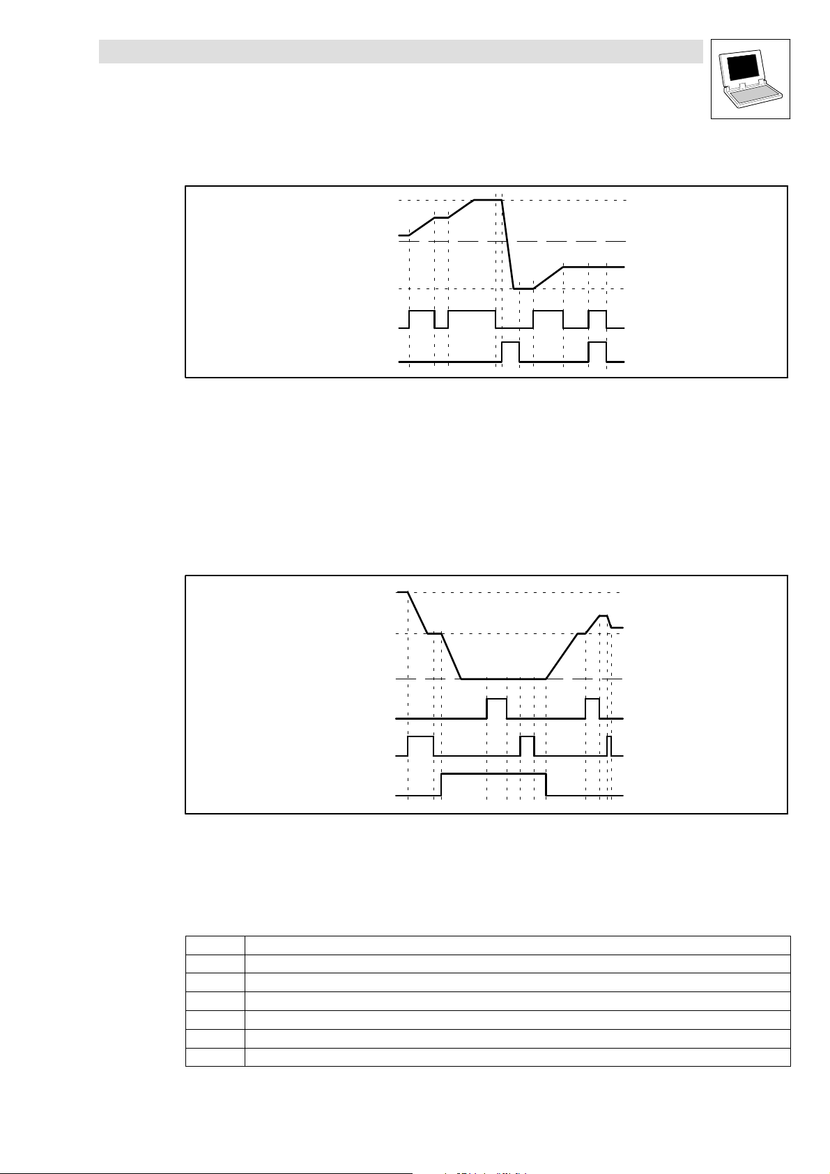
Function library LenzeDrive.lib
Special functions
2.7.3 Motor potentiometer (L_MPOT)
2.7.3.1 Operation of the motor potentiometer
nOut_a
nUp_b
nDown_b
Fig. 2−70 Control signals for the motor potentiometer
bUp_b = TRUE:
– The signal at nOut_a runs up to its upper limit (nHighLimit).
nDown_b = TRUE:
– The signal at nOut_a runs down to its lower limit (nDownLimit).
bUp_b = FALSE and nDown_b = FALSE or bUp_b = TRUE and nDown_b = TRUE:
– The signal at nOut_a does not change.
Deactivation of the motor potentiometer
nOut_a
wTir
wTif
wTir
wTif
wTif
wTir
wTir
wTir
nHighLimit
+
−
0
nLowLimit
nHighLimit
wTif
nLowLimit
bUp_b
bDown_b
bInAct_b
Fig. 2−71 Deactivation of the motor potentiometer
If bInAct_ = TRUE, then the motor potentiometer is deactivated
bInAct_b has priority over bUp_b and bDown_b.
If the motor potentiometer is deactivated, the signal at nOut_a follows the function set by byFunction.
You can set the following functions:
byFunction Meaning
0 No further action; nOut_a retains its value.
1 The motor potentiometer runs down to 0 %, using the run−down time Tif.
2 The motor potentiometer runs down to the lower limit, using the run−down time Tif nLowLimit.
3 The motor potentiometer immediately changes its output to 0 % (Important for the EMERGENCY STOP function).
4 The motor potentiometer immediately changes its output to the lower limit (nLowLimit).
5 The motor potentiometer runs up to the upper limit, using the run−up time Tir nHighLimit).
0
L
LenzeDrive.lib EN 1.7
2−71
Page 82

Function library LenzeDrive.lib
Special functions
2.7.3 Motor potentiometer (L_MPOT)
Activation of the motor potentiometer
If bInAct_b = FALSE, then the motor potentiometer is activated. The function that is now
performed depends on
– the momentary output signal.
– the preset limit values.
– the control signals at bUp_b and bDown_b.
If the signal at nOut_a
– is outside the limits that have been set, then the output signal moves to the nearest limit,
using the Titimes that have been set. The sequence is independent of the control signals at
bUp_b and bDown_b.
– within the limits that have been set, then the output signal moves according to the control
signals at bUp_b and bDown_b.
2.7.3.2 Initialization of the motor potentiometer
On initialization after power−on, the motor potentiometer is loaded with a specific initial value. Under
byInitFunction you can select the initialization function.
byInitFunction Function
0 The output value that is output on power−off, is stored in the internal non−volatile memory of the drive controller. This
1 On mains power−on the lower limit (defined by nLowLimit) is loaded.
2 On mains power−on an initial value = 0 % is loaded.
value is loaded in again at power−on.
2.7.3.3 Storing the current output value after supply interruption
byInitFunction
bUp_b
bInAct_b
bDown_b
[VAR_GLOBAL RETAIN] [VAR_GLOBAL RETAIN]
Fig. 2−72 Programming to store the current output value after a supply interruption
dnActRetain
byFunction
In order to store the latest value at nOut_a after a supply interruption, you must declare a global
variable of type RETAIN (VAR_GLOBAL RETAIN). Combine the variable as described in Fig. 2−72.
The current value at nOut_a is always stored in this variable. The variable will hold the value
after a supply interruption.
When the power is switched on again, the stored value is read into the FB L_MPOT from the
variable and applied as the starting value.
CTRL
nHighLimit
wTir
wTif
nLowLimit
L_MPOT
nOut_a
dnActRetain
2−72
LenzeDrive.lib EN 1.7
L
Page 83

Function library LenzeDrive.lib
Special functions
2.7.4 Speed preconditioning (L_NSET)
2.7.4 Speed preconditioning (L_NSET)
This FB conditions the main speed setpoint as well as an additional setpoint (or other signals) for the
subsequent controller structure by using a ramp generator or fixed speeds.
nCInhVal_a
bRfgStop_b
bRfg0_b
bNSetInv_b
nNSet_a
bJog1_b
bJog2_b
bJog4_b
bJog8_b
bTI1_b
bTI2_b
bTI4_b
bTI8_b
nSet_a
bLoad_b
bNAddInv_b
nNAdd_a
DMUX
0
3
DMUX
0
3
0
15
0
15
Fig. 2−73 Speed preconditioning (L_NSET)
anJogSetValue(0)
anJogSetValue(1)
...
anJogSetValue(14)
JOG 0...15
dnTir
adnTir(0)
adnTir(1)
...
adnTir(14)
TI 0...15
CINH
dnTif
adnTif(0)
adnTif(1)
adnTif(14)
1bExternalCINH_b
32767
L_NSET
nNOut_a
bRfgIEqO_b
ramp generator main setpoint
linking main
S-shape
main setpoint
0
1
1
...
0
1
1
ramp generator additional setpoint
nTiSShaped
bSShapeActive
dnTirAdd
dnTifAdd
setpoint and
additional setpoint
byArithFunction
x
+-
*
/
x/(1-y)
y
nIEqOHysterisis
Variable name Data type Signal type Variable type Comment
nCInhVal_a Integer analog VAR_INPUT Here the signal is applied that the main setpoint
integrator is to accept when the controller is inhibited
(CINH).
bRfgStop_b Bool binary VAR_INPUT Holding (freezing) of the main setpoint integrator to its
current value.
bRfg0_b Bool binary VAR_INPUT Leads the main−setpoint integrator via the current
Ti−times to 0.
bNSetInv_b Bool binary VAR_INPUT Control of the signal inversion for the main setpoint.
nNSet_a Integer analog VAR_INPUT Provided for main setpoint; other signals are
permissible.
bJog1_b Bool binary VAR_INPUT
bJog2_b Bool binary VAR_INPUT
Selection and control of overriding "fixed setpoints"
for the main setpoint.
bJog4_b Bool binary VAR_INPUT
bJog8_b Bool binary VAR_INPUT
bTI1_b Bool binary VAR_INPUT
bTI2_b Bool binary VAR_INPUT
Selection and control of alternative "fixed setpoints"
for the main setpoint.
bTI4_b Bool binary VAR_INPUT
bTI8_b Bool binary VAR_INPUT
nSet_a Integer analog VAR_INPUT Here the signal is applied that the main−setpoint
integrator is to accept when bLoad_b = TRUE.
bLoad_b Bool binary VAR_INPUT Control of the two ramp generators in special
situations, e.g. quick stop (QSP)
bAddInv_b Bool binary VAR_INPUT Control of the signal inversion for the additional
setpoint
L
LenzeDrive.lib EN 1.7
2−73
Page 84

Function library LenzeDrive.lib
Special functions
2.7.4 Speed preconditioning (L_NSET)
Variable name CommentVariable typeSignal typeData type
nNAdd_a Integer analog VAR_INPUT Provided for additional setpoint; other signals are
bExternalCINH Bool binary VAR_INPUT Resets the ramp function generator and the additional
nNOut_a Integer analog VAR_OUTPUT Speed setpoint (16384 100 % n
bRfgIEqO_b Bool binary VAR_OUTPUT Status check
dnTir Double integer VAR CONSTANT RETAIN Acceleration time Tir for the main setpoint
dnTif Double integer VAR CONSTANT RETAIN Deceleration time Tif for the main setpoint
adnTir[0...14] Array of double
integers
adnTif[0...14] Array of double
integers
anJogSetValue[0...14] Array of integers VAR CONSTANT RETAIN Selectable fixed speeds
bSShapeActive Bool VAR CONSTANT RETAIN S−curve ramp generator characteristic for the main
nTiSShaped Integer VAR CONSTANT RETAIN Ti−time for the S−curve ramp generator
byArithFunction Byte VAR CONSTANT RETAIN Arithmetic function, combines mains and additional
dnTirAdd Double integer VAR CONSTANT RETAIN Acceleration time Tir for the additional setpoint
dnTifAdd Double integer VAR CONSTANT RETAIN Deceleration time Tif for the additional setpoint
nlEqOHysteresis Integer VAR CONSTANT RETAIN Ramp generator threshold for the main setpoint
Parameter codes of the instances
permissible.
ramp generator.
max
VAR CONSTANT RETAIN Acceleration time Tir for the main setpoint
VAR CONSTANT RETAIN Deceleration time Tif for the main setpoint
setpoint
setpoints.
(C0011))
Variable name L_NSET1 Setting range Lenze
dnTir C0012 0.000 ... 999.900 sec 0.000
adnTir[0...14] C0101/1 ... 15 0.000 ... 999.900 sec 0.000
dnTif C0013 0.000 ... 999.900 sec 0.000
adnTif[0...14] C0103/1 ... 15 0.000 ... 999.900 sec 0.000
anJogSetValue[0...14] C0039/1 ... 15 −199.99 ... 199.99% 0.00
bSShapeActive C0134 0 ... 1 0
nTiSShaped C0182 0.01 ... 50.00 sec 20.00
byArithFunction C0190 0 ... 5 0
dnTirAdd C0220 0.000 ... 999.900 sec 0.000
dnTifAdd C0221 0.000 ... 999.900 sec 0.000
nlEqOHysteresis C0241 0.00 ... 100.00% 1.00
2.7.4.1 Main setpoint channel
The signals in the main setpoint channel are limited to the range of ±32767.
The signal at nNSet_a is initially led by the function JOG−select.
A selected JOG value switches the input nNSet_a inactive. Then the following signal
conditioning uses the JOG value.
2−74
LenzeDrive.lib EN 1.7
L
Page 85

Function library LenzeDrive.lib
Special functions
2.7.4 Speed preconditioning (L_NSET)
2.7.4.2 JOG setpoints
JOG setpoints are fixed values that are stored under anJogSetValue[0] ... anJogSetValue[14] in the
memory.
The JOG values can be called up from the memory by bJog1_b ... bJog8_b.
– These inputs are binary coded, so that 15 JOG values can be called.
The decoding for the enabling of the JOG values (calling from the memory) is carried out
according to the following table:
Main setpoint of bJog8_b bJog4_b bJog2_b bJog1_b
nNSet_a 0 0 0 0
anJogSetValue[0] 0 0 0 1
anJogSetValue[1] 0 0 1 0
anJogSetValue[2] 0 0 1 1
anJogSetValue[3] 0 1 0 0
anJogSetValue[4] 0 1 0 1
anJogSetValue[5] 0 1 1 0
anJogSetValue[6] 0 1 1 1
anJogSetValue[7] 1 0 0 0
anJogSetValue[8] 1 0 0 1
anJogSetValue[9] 1 0 1 0
anJogSetValue[10] 1 0 1 1
anJogSetValue[11] 1 1 0 0
anJogSetValue[12] 1 1 0 1
anJogSetValue[13] 1 1 1 0
anJogSetValue[14] 1 1 1 1
0 = FALSE
1 = TRUE
The number of VAR_INPUT variables to be assigned depends on the number of JOG setpoints
required. A maximum of 4 VAR_INPUT variables and thus 15 selection possibilities are
available.
Number of the required JOG setpoints Number of VAR_INPUT (bJog1_b ... bJog8_b) to be assigned
1 at least 1
1 ... 3 at least 2
4 ... 7 at least 3
8 ... 15 4
2.7.4.3 Setpoint inversion
The output signal of the JOG function is led via an inverter.
The sign of the setpoint is inverted, when bNSetInv_b switches = TRUE .
L
LenzeDrive.lib EN 1.7
2−75
Page 86

Function library LenzeDrive.lib
Special functions
2.7.4 Speed preconditioning (L_NSET)
2.7.4.4 Ramp generator for the main setpoint
The setpoint is then led via a ramp generator with a linear characteristic. The ramp generator converts
setpoint jumps at the input into a ramp.
[%]
RFG−OUT
100%
w2
w1
0
t
ir
t
if
t
T
ir
Tir+ t
Fig. 2−74 Acceleration and deceleration times of the ramp generator
w1 ,w2 Change of the main setpoint, depending on tir or t
RFG−OUT Output of the ramp generator
T
−times are fixed values that are stored under
i
100%
ir
w2 * w1
– adnTir[0] ... adnTir[14] (ramp−up times) and
– adnTif[0] ... adnTif[14] (ramp−down times) in the memory.
The T
−times can be called from the memory by bTI1_b ... bTI8_b
i
– These inputs are binary coded, so that 16 Ti−times can be called.
– The Ti−times can only be activated in pairs.
The decoding for the enabling of the T
−times (calling from the memory) is made according to
i
the following plan:
Acceleration time Deceleration time bTI8_b bTI4_b bTI2_b bTI1_b
dnTir dnTif 0 0 0 0
adnTir[0] adnTif[0] 0 0 0 1
adnTir[1] adnTif[1] 0 0 1 0
adnTir[2] adnTif[2] 0 0 1 1
adnTir[3] adnTif[3] 0 1 0 0
adnTir[4] adnTif[4] 0 1 0 1
adnTir[5] adnTif[5] 0 1 1 0
adnTir[6] adnTif[6] 0 1 1 1
adnTir[7] adnTif[7] 1 0 0 0
adnTir[8] adnTif[8] 1 0 0 1
adnTir[9] adnTif[9] 1 0 1 0
adnTir[10] adnTif[10] 1 0 1 1
adnTir[11] adnTif[11] 1 1 0 0
adnTir[12] adnTif[12] 1 1 0 1
adnTir[13] adnTif[13] 1 1 1 0
adnTir[14] adnTif[14] 1 1 1 1
0 = FALSE
1 = TRUE
Tif+ t
if
T
if
100%
if
w2 * w1
2−76
LenzeDrive.lib EN 1.7
L
Page 87

Function library LenzeDrive.lib
Special functions
2.7.4 Speed preconditioning (L_NSET)
When the controller inhibit (CINH) is set, the ramp generator accepts the value at nCInhVal_a
and passes it on to the following function.
This function has priority over all other functions.
bRfgStop_b = TRUE:
– The ramp generator is stopped. Changes at the input of the ramp generator have no effect
on the output signal.
bRfg0_b = TRUE:
– The ramp generator decelerates to zero along its deceleration ramp.
It is also possible to load the ramp generator online with a defined value. For this bLoad_b
must be set = TRUE. As long as this input is set, the value at nNSet_a is accepted by the ramp
generator and provided at the output.
Priorities:
CINH bLoad_b bRfg0_b bRfgStop_b Function
0 0 0 0 RFG follows the input value via the set ramps.
0 0 0 1 The value at the output of RFG is frozen.
0 0 1 0 RFG decelerates to zero along the set deceleration ramp.
0 0 1 1
0 1 0 0 RFG takes the value at nSet_a and provides it at its output.
0 1 0 1
0 1 1 0
0 1 1 1
1 0 0 0 RFG takes the value at nCInhVal_a and provides it at its output.
1 0 0 1
1 0 1 0
1 0 1 1
1 1 0 0
1 1 0 1
1 1 1 0
1 1 1 1
0 = FALSE
1 = TRUE
2.7.4.5 S−ramp
A PT1 element is connected to the linear ramp generator. This arrangement implements an S−ramp
for an almost jerk−free acceleration and deceleration.
The PT1 section is switched on/off with bSShapeActive.
The time constant is set with nTiSShaped.
2.7.4.6 Arithmetic operation
The arithmetic module makes an arithmetical combination of the main setpoint and the additional
setpoint. The arithmetical combination is selected by byArithFunction.
byArithFunction Function Example
0 nNout_a = x (y is not processed)
1 nNout_a = x + y
2 nNout_a = x − y
3 nNout_a = x * y
4 nNout_a = x / |y|
5 nNout_a = x / (100% − y)
nNOut_a +
nNOut_a +
nNOut_a +
x @ y
16384
x
@ 164
|y|
x
16384 * y
@ 16384
L
LenzeDrive.lib EN 1.7
2−77
Page 88

Function library LenzeDrive.lib
Special functions
2.7.4 Speed preconditioning (L_NSET)
2.7.4.7 Additional setpoint
Via nNAdd_a you can combine an additional setpoint (e.g. a correction signal) with the main
setpoint.
Via bNAddInv_b you can invert the input signal, before it is applied to the ramp generator. The
ramp generator has a linear characteristic. Its Ti−times are set with dnTirAdd (ramp−up time)
and dnTifAdd (ramp−down time).
If bLoad_b = TRUE, the ramp generator is set to 0 and held there, without considering the
Ti−times. The same applies when controller inhibit (CINH) is set.
2−78
LenzeDrive.lib EN 1.7
L
Page 89

Function library LenzeDrive.lib
Special functions
2.7.5 Process controller (L_PCTRL)
2.7.5 Process controller (L_PCTRL)
This FB is used, for instance, as a higher−level controller (dancer position controller, tension
controller, pressure controller, etc.).
Setpoint and actual value are sent to the process controller via the corresponding inputs and
processed according to the selected control algorithm (PID−, PI− or P−algorithm).
Fig. 2−75 Process controller (L_PCTRL)
VariableName DataType SignalType VariableType Note
nAdapt_a Integer analog VAR_INPUT Gain V
nSet_a Integer analog VAR_INPUT Input of the process setpoint.
nAct_a Integer analog VAR_INPUT Actual value input
bInAct_b Bool binary VAR_INPUT Deactivation of the process controller.
bIOff_b Bool binary VAR_INPUT Set I−component to 0.
nInflu_a Integer analogs VAR_INPUT Evaluation or suppression of the output signal.
nOut_a Integer analog VAR_OUTPUT Output signal. Value range ±16384 (bipolar), or
nActVp Integer − VAR_OUTPUT Shows the actual gain.
nVp Integer − VAR CONSTANT RETAIN Gain Vp (10 1.0)
dnTn Double integer − VAR CONSTANT RETAIN Integral−action time Tn (20 20 ms)
nKd Integer − VAR CONSTANT RETAIN Differential component Kd (10 1.0)
nVp2Adapt Integer − VAR CONSTANT RETAIN Vp2 − process controller adaptation (64 1.0)
nVp3Adapt Integer − VAR CONSTANT RETAIN Vp3 − process controller adaptation (64 1.0)
nSet1Adapt Integer − VAR CONSTANT RETAIN Set1 − process controller adaptation (16384 100.00
nSet2Adapt Integer − VAR CONSTANT RETAIN Set2 − process controller adaptation (16384 100.00
byPCharacteristic Byte − VAR CONSTANT RETAIN Function selection for the provision of the P−gain
dnTir Double integer − VAR CONSTANT RETAIN Acceleration time Tir (1000 1.000 s)
dnTif Double integer − VAR CONSTANT RETAIN Deceleration time Tif (1000 1.000 s)
bBiUnipolar Bool − VAR CONSTANT RETAIN Value range of the output signal
n A d a p t _ a
n S e t _ a
n A c t _ a
b I n A c t _ b
b I O f f _ b
n I n f l u _ a
b y P C h a r a c t e r i s t i c
n V p
V p
n V p
n V p 2 A d a p t
s o l l 1 s o l l 2
b B i U n i p o l a r
R E S E T
d n T n
n K d
V p 2
V p
V p 2
V p 3
n V p
n V p 2 A d a p t
n V p 3 A d a p t
n S e t 2 A d a p t
± 1 6 3 8 4
2
3
n S e t 1 A d a p t
d n T i r
d n T i f
L _ P C T R L
0
1
n A c t V p
2
3
n O u t _ a
p
Value range: ±32767
You can alter the gain online.
Range of possible values: ±32767
The rate of change of step−change signals can be
slowed by using the ramp generator (with dnTir
and dnTif).
Value range: ±32767
You can carry out this function online.
You can carry out this function online.
Value range: ±32767
0 ... 16384 (unipolar)
%)
%)
L
LenzeDrive.lib EN 1.7
2−79
Page 90

Function library LenzeDrive.lib
Special functions
2.7.5 Process controller (L_PCTRL)
Parameter codes of the instances
VariableName L_PCTRL1 SettingRange Lenze
nVp C0222 0.1 ... 500.0 1.0
dnTn C0223 20 ... 99999 ms 400
nKd C0224 0.0 ... 5.0 0.0
nVp2Adapt C0325 0.1 ... 500.0 1.0
nVp3Adapt C0326 0.1 ... 500.0 1.0
nSet1Adapt C0328 0.00 ... 100.00 % 0.00
nSet2Adapt C0327 0.00 ... 100.00 % 100.00
byPCharacteristic C0329 0 ... 3 0
dnTir C0332 0.000 ... 999.900 sec 0.000
dnTif C0333 0.000 ... 999.900 sec 0.000
bBiUnipolar C0337 0 ... 1 0
Range of functions
Control characteristic
Ramp generator
Value range of the output signal
Evaluation of the output signal
Deactivation of the process controller
2.7.5.1 Control characteristic
In the default setting, the PID algorithm is active.
Differential component K
You can deactivate the Kd−component by setting nKd = 0.0. The controller now becomes a
PI−controller (or P−controller if the I−component is also switched off).
Integral−action component I
You can switch off the I−component with
bIOff_b = TRUE, or on with
bIOff_b = FALSE.
Switching on and off can also be done online. If the I−component is to be switched off permanently,
set bIOff_b to TRUE.
Integral−action time T
By using nTn you can set the parameter for the integral−action time.
n
d
2−80
LenzeDrive.lib EN 1.7
L
Page 91

Function library LenzeDrive.lib
Special functions
2.7.5 Process controller (L_PCTRL)
Gain V
p
The gain Vp can be set in different ways. By using byPCharacteristic you can select the function you
require.
With nActVp you can display the actual value of the gain Vp.
byPCharacteristic = 0:
The gain V
is provided by nVp.
p
byPCharacteristic = 1:
Fig. 2−76 The gain Vp is provided by nAdapt_a
The gain V
is provided by nAdapt_a. The input value is led via a linear characteristic. The
p
slope of the characteristic is fixed by nVp(upper limit) and nVp2Adapt (lower limit). The value in
nVp is valid if the input value = +100 % or −100 % (100 % = 16384). The value in nVp2Adapt is
valid if the input value = 0.
byPCharacteristic = 2:
V
p
nV
p
nV
p2Adapt
nAdapt_a
0
100%
V
nSet1Adapt
Fig. 2−77 The gain Vp derived from the process setpoint nSet_a
The gain V
is derived from the process setpoint nSet_a. The setpoint is acquired after the
p
ramp generator, and calculated from a characteristic with 3 interpolation points.
byPCharacteristic = 3:
The gain V
is derived from the control difference, and led by the same characteristic
p
generation as for byPCharacteristic = 2.
p
nV
p
nV
p2Adapt
nV
p3Adapt
nSet_a
nSet2Adapt
L
LenzeDrive.lib EN 1.7
2−81
Page 92
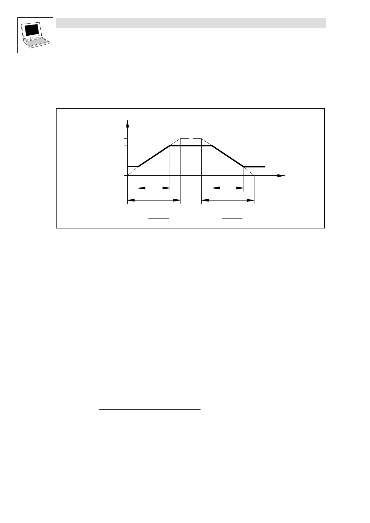
Function library LenzeDrive.lib
Special functions
2.7.5 Process controller (L_PCTRL)
2.7.5.2 Ramp generator
The setpoint at nSet_a is led via a ramp generator with a linear characteristic
(100 % 16384 n
This means that setpoint jumps at the input can be converted into a ramp.
RFG−OUT
100%
(C0011)).
max
[%]
w2
w1
0
t
ir
t
ir
t
if
t
if
t
Tir+ t
Fig. 2−78 Acceleration and deceleration times of the ramp generator
w1 ,w2 Change of the main setpoint, depending on tir or t
RFG−OUT Output of the ramp generator
100%
ir
w2 * w1
The ramps can be adjusted separately for acceleration and deceleration:
– Acceleration time tir with dnTir
– Deceleration time tif with dnTif
Using bInAct_b = TRUE sets the ramp generator immediately to 0.
2.7.5.3 Value range of the output signal
In the factory setting, the process controller has bipolar operation (bBiUnipolar = 0).
– The output signal is limited to ±100 % (±16384).
Using bBiUnipolar = 1 the process controller has unipolar operation.
– The output signal is limited to 0 ... +100 % (0 ... 16384).
2.7.5.4 Evaluation of the output signal
The limitation is followed by an evaluation of the output signal by nInflu_a.
– The calculation is done according to the following formula:
Tif+ t
if
100%
if
w2 * w1
nOut_a +
(Valuesafterthelimitation) @ nInflu_a
16384
2.7.5.5 Deactivation of the process controller
bInAct_b = TRUE deactivates the process controller. This means that
– nOut_a is set = 0.
– the I−component is set = 0.
– the ramp generator is set = 0.
2−82
LenzeDrive.lib EN 1.7
L
Page 93
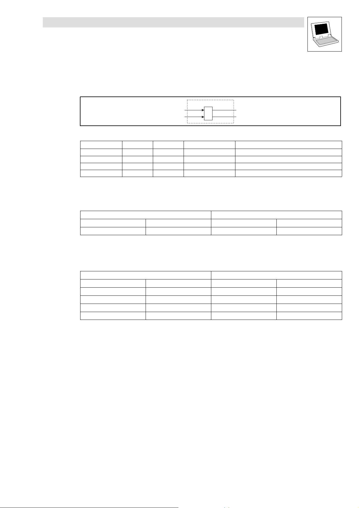
Function library LenzeDrive.lib
Special functions
2.7.6 Right/Left/Quickstop (L_RLQ)
2.7.6 Right/Left/Quickstop (L_RLQ)
This FB links the input for the direction of rotation and the QSP function, and is safe against an open
circuit.
Fig. 2−79 Right/Left/Quickstop (L_RLQ)
VariableName DataType SignalType VariableType Note
bCw_b Bool binary VAR_INPUT Right
bCCw_b Bool binary VAR_INPUT Left
bCwCCw_b Bool binary VAR_OUTPUT Status Right/Left
bQSP_b Bool binary VAR_OUTPUT Set Quickstop
Function
After mains connection and simultaneous TRUE at both inputs, the outputs are set as
follows:
bCw_b bCCw_b bCwCCw_b bQSP_b
1 1 0 1
0 = FALSE
1 = TRUE
The following truth−table results only if the inputs were set to TRUE once after power
switch−on
bCw_b bCCw_b bCwCCw_b bQSP_b
0 0 0 1
1 0 1 0
0 1 1 0
1 1 unchanged unchanged
0 = FALSE
1 = TRUE
If you set both inputs to TRUE during operation, both outputs still have their previous output value.
bCw_b
bCCw_b
Inputs Outputs
Inputs Outputs
L_RLQ
bQSP_b
bCwCCw_b
L
LenzeDrive.lib EN 1.7
2−83
Page 94

Function library LenzeDrive.lib
Special functions
2.7.6 Right/Left/Quickstop (L_RLQ)
2−84
LenzeDrive.lib EN 1.7
L
Page 95

Function library LenzeDrive.lib
3 Appendix
3.1 Code table
How to read the code table:
Column Abbreviation Meaning
Code Cxxxx
1
2
…
[Cxxxx] Parameter value of the code can only be modified when the controller is inhibited.
LCD Keypad LCD
Lenze Lenze setting of the code
Choice 1 {1 %} 99 Minimum value {Smallest step/unit} Maximum value
IMPORTANT − Additional, important explanation of the code
Code Cxxxx
Subcode 1 of code Cxxxx
Subcode 2 of code Cxxxx
…
DIS: Display only
All others are parameter values.
The column IMPORTANT contains further information.
Appendix
Code LCD
C0012 dnTir 0.000 0.000 {0.001 s} 999.900 Acceleration time Tir for the main
Possible settings
Lenze Choice
IMPORTANT Info
setpoint of L_NSET1
Related to the speed change
0 ... n
.
max
C0013 dnTif 0.000 0.000 {0.001 sec} 999.900 Deceleration time Tif for the main
setpoint of L_NSET1
Related to the speed change
n
... 0.
max
C0039
1
anJOGSetValue1
...
...
14
anJOGSetValue14
15
anJOGSetValue15
C0101
1
adnTir1
2
adnTir2
...
...
15
adnTir15
C0103
1
adnTif1
2
adnTif2
...
...
15
adnTif15
C0134 bSShapeActive Ramp generator characteristic for the
C0182 nTiSShaped 20.00 0.01 sec {0.01 sec} 50.00 sec Ti−time of the S−curve ramp generator
0.00
...
0.00
0.00
0.000
0.000
...
0.000
0.000
0.000
...
0.000
0 0 linear
−199.99 {0.01} 199.99 Fixed speeds (JOG setpoints) can be
0.000 {0.001 sec} 999.900 Additional acceleration times Tir for the
selected for L_NSET1 using digital
inputs.
main setpoint of L_NSET1
Related to the speed change
0 ... n
.
max
0.000 {0.001 sec} 999.900 Additional deceleration times Tif for the
main setpoint of L_NSET1
Related to the speed change
n
... 0.
max
main setpoint of L_NSET1
1 S−shaped
Linear S−shaped ^ 2−73
for L_NSET1
Determines the S curve
Low values åsmall S−rounding
High values ålarge S−rounding
^ 2−73
^ 2−73
^ 2−73
^ 2−73
^ 2−73
^ 2−73
^ 2−73
L
LenzeDrive.lib EN 1.7
3−1
Page 96

Function library LenzeDrive.lib
Appendix
Code InfoIMPORTANTPossible settingsLCDCode InfoIMPORTANT
LCD
ChoiceLenze
C0190 byArithFunction 0 0 OUT = C46
1 C46 + C49
2 C46 − C49
3 C46 * C49
4 C46 / C49
5 C46/(100 − C49)
C0220 dnTirAdd 0.000 0.000 {0.001 sec} 999.900 Acceleration time Tir of the additional
Arithmetic block in the function block
L_NSET1
Combines main setpoint C0046 and
additional setpoint C0049.
setpoint for L_NSET1
Related to the speed change
0 ... n
.
max
C0221 dnTifAdd 0.000 0.000 {0.001 sec} 999.900 Deceleration time Tif of the additional
setpoint for L_NSET1
Related to the speed change
n
... 0.
max
C0222 nVp 1.0 0.1 {0.1} 500.0 Gain Vpof L_PCTRL1 ^ 2−79
C0223 nTn 400 20 {1 msec} 99999
C0224 nKd 0.0 0.0 {0.1} 5.0 Differential component Kd of L_PCTRL1 ^ 2−79
C0241 nIEqOHysteresis 1.00 0.00 {0.01 %} 100.00
C0260 nHighLimit 100.00 −199.99 {0.01 %} 199.99 Upper limit of L_MPOT1
99999 ms switched off
100 % = n
max
Integral component Trof L_PCTRL1 ^ 2−79
Threshold ramp generator for main
setpoint of L_NSET1
Input = output
Mandatory is: C0260 > C0261
C0261 nLowLimit −100.0 −199.99 {0.01 %} 199.99 Lower limit of L_MPOT1
Mandatory is: C0261 < C0260
C0262 wTir 10.0 0.1 {0.1 s} 6000.0 Acceleration time Tir of L_MPOT1
Related to change 0 ... 100 %.
C0263 wTif 10.0 0.1 {0.1 s} 6000.0 Deceleration time Tif of L_MPOT1
Related to change 0 ... 100 %.
C0264 byFunction 0
Deactivation function of L_MPOT1
Function which is executed when
motor pot is deactivated via the
input MPOT1−INACTIVE.
0 No function
1 Down to 0 %
2 Down to C261
3 Jump 0 %
4 Jump to C261
5 Up to C260
C0265 byInitFunction 0
No change
Deceleration with Tif to 0 %
Deceleration with Tif to C0261
Inhibit with Tif = 0 to 0 %
Inhibit with Tif = 0 to C0261
Acceleration with Tir to C0260
Initialisation function of L_MPOT1
Value which is accepted during
mains switching and activated
motor pot.
0 Power off
1 C0261
2 0 %
C0325 nVp2Vdapt 1.0 0.1 {0.1} 500.0 Gain adaptation (Vp2) of L_PCTRL1 ^ 2−79
C0326 nVp3Adapt 1.0 0.1 {0.1} 500.0 Gain adaptation (Vp3) of L_PCTRL1 ^ 2−79
C0327 nSet2Adapt 100.00 0.00 {0.01 %} 100.00 Adaptation n
Value during mains failure
Lower limit of C0261: 0 %
of L_PCTRL1
Set speed threshold of the process
controller adaptation
set2
Mandatory is: C0327 > C0328
C0328 nSet1Adapt 0.00 0.00 {0.01 %} 100.00 Adaptation n
Set speed threshold of the process
controller adaptation
of L_PCTRL1
set1
Mandatory is: C0328 < C0327
^ 2−73
^ 2−73
^ 2−73
^ 2−73
^ 2−70
^ 2−70
^ 2−70
^ 2−70
^ 2−70
^ 2−70
^ 2−70
^ 2−70
^ 2−79
^ 2−79
3−2
LenzeDrive.lib EN 1.7
L
Page 97

Function library LenzeDrive.lib
Appendix
Code InfoIMPORTANTPossible settingsLCDCode InfoIMPORTANT
LCD
ChoiceLenze
C0329 byPCharacteristic 0
0 no
1 External Vp
2 Setpoint
3 Ctrl diff
C0332 PCTRLdnTir 0.000 0.000 {0.001 sec} 999.900 Acceleration time Tirof L_PCTRL1
Activate adaptation of L_PCTRL1 ^ 2−79
no process controller adaptation
external via input
Adaptation via setpoint
Adaptation via control difference
Referred to the setpoint change
0 ... 100 %.
C0333 dnTif 0.000 0.000 {0.001 sec} 999.900 Deceleration time Tirof L_PCTRL1
Referred to the setpoint change
0 ... 100 %.
C0337 bBiUnipolar 0 0 bipolar
C0338 byFunction 1 0 OUT = nIn1_a
C0560
1
anSollW1
...
...
14
anSollW14
15
anSollW15
C0600 byFunction 1 0 OUT = nIn1_a
C0620 nGain 1.00 −10.00 {0.01} 10.00 Gain for dead−band component L_DB1 ^ 2−20
C0621 nDeadBand 1.00 0.00 {0.01 %} 100.00 Dead−band of DB1 ^ 2−20
C0630 nMaxLimit 100.00 −199.99 {0.01 %} 199.99 Upper limit of limiter L_LIM1 ^ 2−22
C0631 nMinLimit −100.0 −199.99 {0.01 %} 199.99 Upper limit of limiter L_LIM1 ^ 2−22
C0640 nDelayTime 20.00 0.01 {0.01 sec} 50.00 Time constant of L_PT1_1 ^ 2−23
C0650 nGain 1.00 −320.00 {0.01} 320.00 Gain of L−DT1_1 ^ 2−21
C0651 nDelayTime 1.000 0.005 {0.001 sec} 5.000 Time constant of L_DT1_1 ^ 2−21
C0653 bySensibility 1 1 15 Bit
C0655 nNumerator 1 −32767 {1} 32767 Numerator for L_CONV5 ^ 2−49
C0656 nDenominator 1 1 {1} 32767 Denominator for L_CONV5 ^ 2−49
C0671 dnTir 0.000 0.000 {0.01 sec} 999.900 Acceleration time Tir of ramp generator
C0672 dnTif 0.000 0.000 {0.01 sec} 999.900 Deceleration time Tif of L_RFG1 ^ 2−24
C0680 byFunction 6 1 nIn1 = nIn2
C0681 nHysteresis 1.00 0.00 {0.01 %} 100.00 % Hysteresis of L_CMP1 ^ 2−13
C0682 nWindow 1.00 0.00 {0.01 %} 100.00 % Window of L_CMP1 ^ 2−13
0.00
...
0.00
0.00
1 unipolar
1 nIn1_a + nIn2_a
2 nIn1_a − nIn2_a
3 nIn1_a * nIn2_a
4 nIn1_a / nIn2_a
5 nIn1_a / (100 − nIn2_a)
−199.99 {0.01 %} 199.99 Fixed setpoints for L_FIXSET1 ^ 2−2
1 nIn1_a + nIn2_a
2 nIn1_a − nIn2_a
3 nIn1_a * nIn2_a
4 nIn1_a / nIn2_a
5 nIn1_a / (100 − nIn2_a)
2 14 Bit
3 13 Bit
4 12 Bit
5 11 Bit
6 10 bit
7 9 Bit
2 nIn1 > nIn2
3 nIn1 < nIn2
4 |nIn1| = |nIn2|
5 |nIn1| > |nIn2|
6 |nIn1| < |nIn2|
Effective range bipolar/unipolar of
L_PCTRL1
Function arithmetic block L_ARIT1
Combines inputs nIn1_a and
nIn2_a .
Function arithmetic block L_ARIT2
Combines inputs nIn1_a and
nIn2_a .
Input sensitivity of L_DT1_1 ^ 2−21
L_RFG1
Function comparator L_CMP1
Compares the inputs nIn1 and nIn2
^ 2−79
^ 2−79
^ 2−79
^ 2−79
^ 2−11
^ 2−11
^ 2−24
^ 2−13
L
LenzeDrive.lib EN 1.7
3−3
Page 98

Function library LenzeDrive.lib
Appendix
Code InfoIMPORTANTPossible settingsLCDCode InfoIMPORTANT
LCD
ChoiceLenze
C0685 byFunction 1 1 nIn1 = nIn2
2 nIn1 > nIn2
3 nIn1 < nIn2
4 |nIn1| = |nIn2|
5 |nIn1| > |nIn2|
6 |nIn1| < |nIn2|
C0686 nHysteresis 1.00 0.00 {0.01 %} 100.00 % Hysteresis of L_CMP2 ^ 2−13
C0687 nWindow 1.00 0.00 {0.01 %} 100.00 % Window of L_CMP2 ^ 2−13
C0690 byFunction 1 1 nIn1 = nIn2
2 nIn1 > nIn2
3 nIn1 < nIn2
4 |nIn1| = |nIn2|
5 |nIn1| > |nIn2|
6 |nIn1| < |nIn2|
C0691 nHysteresis 1.00 0.00 {0.01 %} 100.00 % Hysteresis of L_CMP3 ^ 2−13
C0692 nWindow 1.00 0.00 {0.01 %} 100.00 % Window of L_CMP3 ^ 2−13
C0695 byFunction 2 1 dnIn1_p < dnIn2_p
2 |dnIn1_p| < |dnIn2_p|
Function comparator L_CMP2
Compares the inputs nIn1 and nIn2
Function comparator L_CMP3
Compares the inputs nIn1 and nIn2
Function comparator for phase signals
L_PHCMP1
Compares the inputs dnIn1_p and
dnIn2_p
C0710 byFunction 0 0 Rising edge
1 Falling edge
2 Both edges
C0711 wPulseTime 0.001 0.001 {0.001 sec} 60.000 Pulse time of TRANS1 ^ 2−36
C0715 byFunction 0 0 Rising edge
1 Falling edge
2 Both edges
C0716 wPulseTime 0.001 0.001 {0.001 sec} 60.000 Pulse duration of L_TRANS2 ^ 2−36
C0720 byFunction 2 0 On delay
1 Off delay
2 On/Off delay
C0721 wDelayTime 1.000 0.001 {0.001 sec} 60.000 Delay time of L_DIGDEL1 ^ 2−30
C0725 byFunction 0 0 On delay
1 Off delay
2 On/Off delay
C0726 WDelayTime 1.000 0.001 {0.001 sec} 60.000 Delay time of L_DIGDEL2 ^ 2−30
C0940 nNumerator 1 −32767 {1} 32767 Numerator for L_CONV1 ^ 2−49
C0941 nDenominator 1 1 {1} 32767 Denominator for L_CONV1 ^ 2−49
C0945 nNumerator 1 −32767 {1} 32767 Numerator for L_CONV2 ^ 2−49
C0946 nDenominator 1 1 {1} 32767 Denominator for L_CONV2 ^ 2−49
C0950 nNumerator 1 −32767 {1} 32767 Numerator for L_CONV3 ^ 2−49
C0951 nDenominator 1 1 {1} 32767 Denominator for L_CONV3 ^ 2−49
C0955 nNumerator 1 −32767 {1} 32767 Numerator for L_CONV4 ^ 2−49
C0956 nDenominator 1 1 {1} 32767 Denominator for L_CONV4 ^ 2−49
C0960 byFunction 1 1 Function 1
2 Function 2
3 Function 3
C0961 ny0 0.00 0.00 {0.01 %} 199.99 Ordinate of the value−pair
C0962 ny1 50.00 0.00 {0.01 %} 199.99 Ordinate of the value−pair (x1 / y1) of
C0963 ny2 75.00 0.00 {0.01 %} 199.99 Ordinate of the value−pair (x2 / y2) of
C0964 ny100 100.00 0.00 {0.01 %} 199.99 Ordinate of the value−pair
C0965 nx1 50.00 0.01 {0.01 %} 100.00 Abscissa of the value−pair (x1 / y1) of
Edge−evaluation function of L_TRANS1 ^ 2−36
Edge−evaluation function of L_TRANS2 ^ 2−36
Function digital delay component
L_DIGDEL1
Function digital delay component
L_DIGDEL2
Characteristic CURVE1−IN ^ 2−17
(x = 0 % / y0) of L_CURVE1
L_CURVE1
L_CURVE1
(x = 100 % / y100) of L_CURVE1
L_CURVE1
^ 2−40
^ 2−30
^ 2−30
^ 2−17
^ 2−17
^ 2−17
^ 2−17
^ 2−17
3−4
LenzeDrive.lib EN 1.7
L
Page 99

Function library LenzeDrive.lib
Appendix
Code InfoIMPORTANTPossible settingsLCDCode InfoIMPORTANT
LCD
ChoiceLenze
C0966 nx2 75.00 0.01 {0.01 %} 99.00 Abscissa of the value−pair (x2 / y2) of
C0995 byDivision 0 −31 {1} 31 Division factor of phase division
C1000 nDivision 1 0 {1} 31 Factor ^ 2−50
C1010 byFunction 1 0 OUT = dnIn1_p
1 dnIn1_p + dnIn2_p
2 dnIn1_p − dnIn2_p
3 dnIn1_p * dnIn2_p
14 dnIn1_p / dnIn2_p
21 dnIn1_p + dnIn2_p (no limit)
22 dnIn1_p − dnIn2_p (no limit)
C1040 dwTi 100.000 0.001 {0.001 %} 5000.000 Acceleration of L_SRFG1 ^ 2−28
C1041 dwJerk 0.200 0.001 {0.001 sec} 999.999 Jolt of L_SRFG1 ^ 2−28
C1100 byFunction 1 1 Return
2 Hold
C1140 byFunction 0 0 Rising edge
1 Falling edge
2 Both edges
C1141 wPulseTime 0.001 0.001 {0.001 sec} 60.000 Pulse duration of L_TRANS3 ^ 2−36
C1145 byFunction 0 0 Rising edge
1 Falling edge
2 Both edges
C1146 wPulseTime 0.001 0.001 {0.001 sec} 60.000 Pulse duration of L_TRANS4 ^ 2−36
C1150 byMode 0 0 Load perm
1 Load edge
2 Cmp & sub
C1151 dnCmp 2 · 1090 {1} 2000000000 Comparison value of L_PHINTK ^ 2−43
C1170 nNumerator 1 −32767 {1} 32767 Numerator for L_CONV6 ^ 2−49
C1171 nDenominator 1 1 {1} 32767 Denominator for L_CONV6 ^ 2−49
C1207 byFunction 2 1 dnIn1_p < dnIn2_p
2 |dnIn1_p| < |dnIn2_p|
L_CURVE1
L_PHDIV1
Function of L_ARITPH1 ^ 2−38
Function of L_FCNT1 ^ 2−32
Edge−evaluation function of L_TRANS3 ^ 2−36
Edge−evaluation function of L_TRANS4 ^ 2−36
Function of L_PHINTK ^ 2−43
Function comparator for phase signals
L_PHCMP2
Compares the inputs dnIn1_p and
dnIn2_p
C1272 byFunction 2 1 dnIn1_p < dnIn2_p
2 |dnIn1_p| < |dnIn2_p|
Function comparator for phase signals
L_PHCMP3
Compares the inputs dnIn1_p and
dnIn2_p
C2118 0 0 Communication via 2 free PDO channels
1 Communication via SDO 2−channel
Channel selection for communication
via system bus with
L_ParWrite/L_ParRead
^ 2−17
^ 2−42
^ 2−40
^ 2−40
^ 2−55
^ 2−59
L
LenzeDrive.lib EN 1.7
3−5
Page 100

Function library LenzeDrive.lib
Appendix
3−6
LenzeDrive.lib EN 1.7
L
 Loading...