


 Loading...
ThinkSystem SR630
Maintenance Manual
Machine Types: 7X01 and 7X02
Note
Before using this information and the product it supports, be sure to read and understand the safety information and the safety instructions, which are available at: http://thinksystem.lenovofiles.com/help/topic/safety_documentation/pdf_files.html
In addition, be sure that you are familiar with the terms and conditions of the Lenovo warranty for your server, which can be found at:
http://datacentersupport.lenovo.com/warrantylookup
Second Edition (November 2017)
© Copyright Lenovo 2017.
LIMITED AND RESTRICTED RIGHTS NOTICE: If data or software is delivered pursuant to a General Services Administration “GSA” contract, use, reproduction, or disclosure is subject to restrictions set forth in Contract No. GS- 35F-05925.

Contents
Safety . . . . . . . |
. . . . . . . . . . .iii |
Safety inspection checklist |
. . . . . . . . . . . iv |
Chapter 1. Introduction . . . . . . . . . 1 |
|
Specifications . . . . . |
. . . . . . . . . . . 2 |
Firmware updates . . . . . . . . . . . . . . . 9
Configuring the LAN over USB interface |
|
manually . . . . . . . . . . . . . . . . |
12 |
Installing the LAN over USB Windows device |
|
driver . . . . . . . . . . . . . . . . . |
12 |
Tech Tips . . . . . . . . . . . . . . . . . |
13 |
Security advisories . . . . . . . . . . . . . |
13 |
Power on the server . . . . . . . . . . . . . |
14 |
Power off the server . . . . . . . . . . . . . |
14 |
Chapter 2. Server components . . . . |
15 |
Front view . . . . . . . . . . . . . . . . . |
15 |
Operator information panel . . . . . . . . . . |
17 |
Rear view . . . . . . . . . . . . . . . . . |
18 |
Rear view LEDs . . . . . . . . . . . . . . . |
24 |
System board components . . . . . . . . . . |
26 |
System board LEDs . . . . . . . . . . . . . |
27 |
System board jumpers . . . . . . . . . . . . |
28 |
Internal cable routing. . . . . . . . . . . . . |
29 |
Server models with four 3.5-inch SAS/SATA |
|
drives . . . . . . . . . . . . . . . . . |
30 |
Server models with four 3.5-inch SAS/SATA/ |
|
NVMe drives . . . . . . . . . . . . . . |
33 |
Server models with eight 2.5-inch SAS/SATA |
|
drives . . . . . . . . . . . . . . . . . |
34 |
Server models with ten 2.5-inch SAS/SATA/ |
|
NVMe drives . . . . . . . . . . . . . . |
37 |
Server models with ten 2.5-inch NVMe |
|
drives . . . . . . . . . . . . . . . . . |
41 |
Parts list. . . . . . . . . . . . . . . . . . |
42 |
Power cords . . . . . . . . . . . . . . |
46 |
Chapter 3. Hardware replacement procedures . . . . . . . . . . . . . . . 47
Installation Guidelines . . . . . . . . . . . . |
47 |
System reliability guidelines . . . . . . . . |
48 |
Working inside the server with the power on . . 49 |
|
Handling static-sensitive devices . . . . . . |
49 |
Top cover replacement . . . . . . . . . . . . |
49 |
Remove the top cover . . . . . . . . . . |
50 |
Install the top cover . . . . . . . . . . . |
51 |
Air baffle replacement . . . . . . . . . . . . |
52 |
Remove the air baffle . . . . . . . . . . . |
53 |
Install the air baffle . . . . . . . . . . . . |
54 |
Rack latches replacement . . . . . . . . . . . |
55 |
Remove the rack latches . . . . . . . . . |
55 |
Install the rack latches . . . . . . . . . . |
57 |
Security bezel replacement . . . . . . . . . . |
59 |
Remove the security bezel . . . . . . . . . |
59 |
Install the security bezel . . . . . . . . . . |
60 |
System fan replacement . . . . . . . . . . . |
62 |
Remove a system fan. . . . . . . . . . . |
62 |
Install a system fan. . . . . . . . . . . . |
63 |
DIMM replacement . . . . . . . . . . . . . |
65 |
Remove a DIMM. . . . . . . . . . . . . |
65 |
DIMM installation rules . . . . . . . . . . |
66 |
Install a DIMM . . . . . . . . . . . . . |
71 |
Hot-swap drive replacement . . . . . . . . . . |
72 |
Remove a hot-swap drive . . . . . . . . . |
73 |
Install a hot-swap drive . . . . . . . . . . |
74 |
LOM adapter replacement . . . . . . . . . . |
76 |
Remove the LOM adapter . . . . . . . . . |
76 |
Install the LOM adapter . . . . . . . . . . |
77 |
Riser card replacement . . . . . . . . . . . . |
77 |
Remove a riser card . . . . . . . . . . . |
78 |
Install a riser card . . . . . . . . . . . . |
80 |
PCIe adapter replacement. . . . . . . . . . . |
82 |
Remove a PCIe adapter . . . . . . . . . . |
82 |
Install a PCIe adapter . . . . . . . . . . . |
83 |
Install a GPU with the GPU upgrade kit . . . . 84 |
|
Backplane replacement. . . . . . . . . . . . |
85 |
Remove the backplane for four 3.5-inch hot- |
|
swap drives . . . . . . . . . . . . . . |
86 |
Install the backplane for four 3.5-inch hot- |
|
swap drives . . . . . . . . . . . . . . |
87 |
Remove the backplane for eight 2.5-inch hot- |
|
swap drives . . . . . . . . . . . . . . |
88 |
Install the backplane for eight 2.5-inch hot- |
|
swap drives . . . . . . . . . . . . . . |
89 |
Remove the backplane for ten 2.5-inch hot- |
|
swap drives . . . . . . . . . . . . . . |
90 |
Install the backplane for ten 2.5-inch hot- |
|
swap drives . . . . . . . . . . . . . . |
90 |
Remove the rear backplane . . . . . . . . |
91 |
Install the rear backplane . . . . . . . . . |
93 |
CMOS battery replacement . . . . . . . . . . |
95 |
Remove the CMOS battery . . . . . . . . |
95 |
Install the CMOS battery . . . . . . . . . |
97 |
TCM replacement (for China only) . . . . . . . . |
98 |
Remove the TCM (for China only) . . . . . . |
99 |
Install the TCM (for China only) . . . . . . . |
100 |
Rear hot-swap drive assembly replacement . . . . 101
© Copyright Lenovo 2017 |
i |
Remove the rear hot-swap drive assembly . |
. |
101 |
Install the rear hot-swap drive assembly . . |
. |
102 |
RAID adapter replacement . . . . . . . . . |
. |
104 |
Remove the RAID adapter . . . . . . . . |
. |
104 |
Install the RAID adapter . . . . . . . . . |
. |
105 |
Serial port module replacement . . . . . . . |
. |
106 |
Remove the serial port module . . . . . . |
. |
106 |
Install the serial port module . . . . . . . |
. |
108 |
M.2 backplane and M.2 drive replacement . . . |
. |
110 |
Remove the M.2 backplane and M.2 drive. . |
. 110 |
|
Adjust the retainer on the M.2 backplane . . |
. |
111 |
Install the M.2 backplane and M.2 drive. . . |
. |
112 |
RAID super capacitor module replacement . . . |
. |
115 |
Remove a RAID super capacitor module on |
|
|
the bottom of the air baffle . . . . . . . . |
. |
115 |
Install a RAID super capacitor module on the |
|
|
bottom of the air baffle . . . . . . . . . |
. |
116 |
Remove the RAID super capacitor module on
the chassis . . . . . . . . . . . . . . . 117
Install the RAID super capacitor module on
the chassis . . . . . . . . . . . . . . . 118
Front I/O assembly replacement . . . |
. . . . . 121 |
Remove the front I/O assembly . . |
. . . . . 122 |
Install the front I/O assembly . . . |
. . . . . 122 |
Hot-swap power supply replacement . |
. . . . . 123 |
Remove a hot-swap power supply. |
. . . . . 123 |
Install a hot-swap power supply . |
. . . . . 128 |
Processor and heat sink replacement . |
. . . . . 134 |
Remove a processor and heat sink |
. . . . . 134 |
Install a processor and heat sink . |
. . . . . 137 |
System board replacement . . . . . |
. . . . . 141 |
Remove the system board . . . . |
. . . . . 142 |
Install the system board . . . . . |
. . . . . 143 |
Update the Universal Unique Identifier
(UUID). . . . . . . . . . . . . . . . . 144 Update the DMI/SMBIOS data . . . . . . . 146 Enable TPM/TCM . . . . . . . . . . . . 148 Enable UEFI Secure Boot . . . . . . . . . 150 Complete the parts replacement . . . . . . . . 151
Chapter 4. Problem
determination . . . . . . . . . . . . .153
Event logs . . . . . . . . . . . . . . . . |
. |
153 |
General problem determination procedures . . . |
. |
155 |
Resolving suspected power problems . . . |
. |
155 |
Resolving suspected Ethernet controller |
|
|
problems . . . . . . . . . . . . . . |
. |
156 |
Troubleshooting by symptom . . . . . . . . |
. |
156 |
Power on and power off problems . . . . . |
. |
157 |
Memory problems . . . . . . . . . . . |
. |
158 |
Hard disk drive problems . . . . . . . . |
. |
159 |
Monitor and video problems . . . . . . . |
. |
161 |
Keyboard, mouse, or USB-device |
|
|
problems . . . . . . . . . . . . . . |
. |
162 |
Optional-device problems . . . . . . . . |
. |
163 |
Serial-device problems . . . . . . . . . |
. |
165 |
Intermittent problems. . . . . . . . . . |
. |
165 |
Power problems . . . . . . . . . . . . . 166 Network problems . . . . . . . . . . . . 166 Observable problems. . . . . . . . . . . 167 Software problems . . . . . . . . . . . . 169
Appendix A. Getting help and
technical assistance . . . . . . . . . .171
Before you call . . . . . . . . . . . . . . . 171 Collecting service data . . . . . . . . . . . . 172 Contacting Support . . . . . . . . . . . . . 173
Appendix B. Notices. . . . . . . . . .175
Trademarks . . . . . . . . . . . . . . . . 176 Important notes . . . . . . . . . . . . . . . 176 Particulate contamination . . . . . . . . . . . 176 Telecommunication regulatory statement . . . . . 177 Electronic emission notices . . . . . . . . . . 177
Taiwan BSMI RoHS declaration . . . . . . . 178 Taiwan import and export contact information . . . 178
Index . . . . . . . . . . . . . . . . . .179
ii ThinkSystem SR630 Maintenance Manual
Safety
Before installing this product, read the Safety Information.
Antes de instalar este produto, leia as Informações de Segurança.
Læs sikkerhedsforskrifterne, før du installerer dette produkt.
Lees voordat u dit product installeert eerst de veiligheidsvoorschriften.
Ennen kuin asennat tämän tuotteen, lue turvaohjeet kohdasta Safety Information. Avant d'installer ce produit, lisez les consignes de sécurité.
Vor der Installation dieses Produkts die Sicherheitshinweise lesen.
Prima di installare questo prodotto, leggere le Informazioni sulla Sicurezza.
Les sikkerhetsinformasjonen (Safety Information) før du installerer dette produktet.
© Copyright Lenovo 2017 |
iii |
Antes de instalar este produto, leia as Informações sobre Segurança.
Antes de instalar este producto, lea la información de seguridad.
Läs säkerhetsinformationen innan du installerar den här produkten.
Safety inspection checklist
Use the information in this section to identify potentially unsafe conditions with your server. As each machine was designed and built, required safety items were installed to protect users and service technicians from injury.
CAUTION:
This equipment must be installed by trained service personnel, as defined by the NEC and IEC 60950- 1, Second Edition, the standard for Safety of Information Technology Equipment. Lenovo assumes you are qualified in the servicing of equipment and trained in recognizing hazards in products with hazardous energy levels.
Important: Electrical grounding of the server is required for operator safety and correct system function. Proper grounding of the electrical outlet can be verified by a certified electrician.
Use the following checklist to verify that there are no potentially unsafe conditions:
1.Make sure that the power is off and the power cord is disconnected.
2.Check the power cord.
•Make sure that the third-wire ground connector is in good condition. Use a meter to measure thirdwire ground continuity for 0.1 ohm or less between the external ground pin and the frame ground.
•Make sure that the power cord is the correct type.
To view the power cords that are available for the server:
a.Go to: http://lesc.lenovo.com
b.In the Customize a Model pane:
1) Click Select Options/Parts for a Model |
. |
2) Enter the machine type and model for your server.
iv ThinkSystem SR630 Maintenance Manual
c. Click the Power tab to see all line cords.
• Make sure that the insulation is not frayed or worn.
3.Check for any obvious non-Lenovo alterations. Use good judgment as to the safety of any non-Lenovo alterations.
4.Check inside the server for any obvious unsafe conditions, such as metal filings, contamination, water or other liquid, or signs of fire or smoke damage.
5.Check for worn, frayed, or pinched cables.
6.Make sure that the power-supply cover fasteners (screws or rivets) have not been removed or tampered with.
© Copyright Lenovo 2017 |
v |
vi ThinkSystem SR630 Maintenance Manual
Chapter 1. Introduction
The ThinkSystem SR630 server is a 1U rack server designed to be highly flexible to support many kinds of Information Technology (IT) workloads. This high-performance, multi-core server is ideally suited for IT environments that require superior processor performance, input/output (I/O) flexibility, and flexible manageability.
Performance, ease of use, reliability, and expansion capabilities were key considerations in the design of the server. These design features make it possible for you to customize the system hardware to meet your needs today and provide flexible expansion capabilities for the future.
The server comes with a limited warranty. For details about the warranty, see: https://datacentersupport.lenovo.com/documents/ht100742
For details about your specific warranty, see:
http://datacentersupport.lenovo.com/warrantylookup
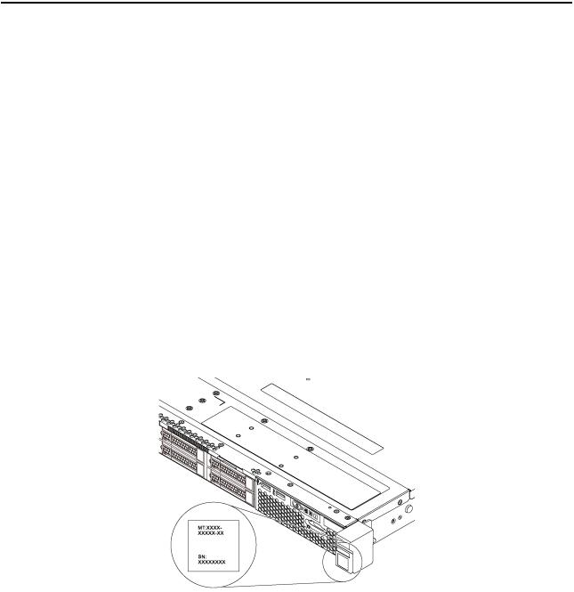
Identifying your server
When you contact Lenovo for help, the machine type and serial number information helps support technicians to identify your server and provide faster service.
The machine type and serial number are on the ID label on the right rack latch in the front of the server.
Figure 1. Location of the ID label
XClarity Controller network access label
The XClarity Controller network access label is attached on the top side of the pull-out information tab. After you get the server, peel the XClarity Controller network access label away and store it in a safe place.
© Copyright Lenovo 2017 |
1 |
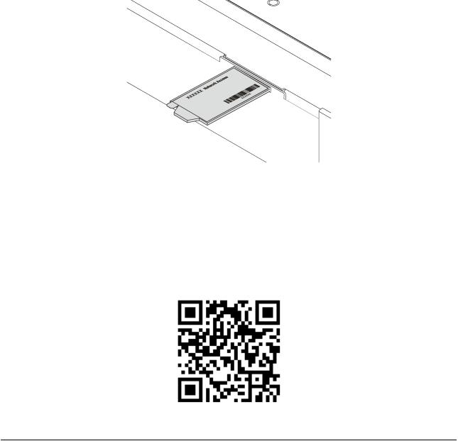
Figure 2. Location of the XClarity Controller network access label
Quick response code
The system service label, which is on the top cover, provides a quick response (QR) code for mobile access to service information. Scan the QR code with a mobile device and a QR code reader application to get quick access to the Lenovo Service web site for this server. The Lenovo Service Information Web site provides additional information for parts installation and replacement videos, and error codes for server support.
The following illustration shows the QR code: https://support.lenovo.com/p/servers/sr630
Figure 3. QR code
Specifications
The following information is a summary of the features and specifications of the server. Depending on the model, some features might not be available, or some specifications might not apply.
2 ThinkSystem SR630 Maintenance Manual
Table 1. Server specifications
 Specification
Dimension
 Weight
Processor (depending on the model)
DIMM
 Description
•1U
•Height: 43.0 mm (1.7 inches)
•Width:
–With rack latches: 482.0 mm (19.0 inches)
–Without rack latches: 434.4 mm (17.1 inches)
•Depth: 778.3 mm (30.7 inches)
Note: The depth is measured with rack latches and power supply installed, but without security bezel installed.
 Up to 19.0 kg (41.9 lb)
•Up to two Intel® Xeon® processors
•Up to 28 cores
•Designed for Land Grid Array (LGA) 3647 socket
•Thermal Design Power (TDP): up to 205 watts
For more important information about the processor, refer to “Important information for system board, processor, and heat sink” on page 8.
For a list of supported processors, see:
http://www.lenovo.com/us/en/serverproven/
•Minimum: 8 GB
•Maximum:
–768 GB using registered DIMMs (RDIMMs)
–1.5 TB using load-reduced DIMMs (LRDIMMs)
–3 TB using three-dimensional stack registered DIMMs (3DS RDIMMs)
•Type:
–PC4-21300 (DDR4-2666), operating speed depends on processor model and UEFI Operating Mode selection
–Single-rank, dual-rank, quad-rank, or octa-rank
–RDIMM, LRDIMM, or 3DS RDIMM
•Slots: 24 DIMM slots
•Supports (depending on the model):
–8 GB, 16 GB, and 32 GB RDIMMs
–64 GB LRDIMMs
–128 GB 3DS RDIMMs
For a list of supported DIMMs, see:
http://www.lenovo.com/us/en/serverproven/
Chapter 1. Introduction 3

Table 1. Server specifications (continued)
 Specification
Internal drives
PCIe slots
Graphics processing unit (GPU)
 Description
•Up to two M.2 drives
•Up to four 3.5-inch hot-swap SAS/SATA drives
•Up to four 3.5-inch hot-swap SAS/SATA/NVMe drives
•Up to eight 2.5-inch hot-swap SAS/SATA drives
•Up to ten 2.5-inch hot-swap SAS/SATA/NVMe drives (NVMe drives are supported only in drive bays 6–9)
•Up to ten 2.5-inch hot-swap NVMe drives
•Up to two 2.5-inch hot-swap SAS/SATA drives in the rear (the processor TDP should be less than or equal to 125 watts)
Notes:
–NVMe drives means Non-Volatile Memory express drives.
–Only use M.2 drives provided by Lenovo.
–480 GB M.2 drives are only supported on M.2 backplane with two M.2 drive slots.
–For server models with the backplane for four 3.5-inch SAS/SATA/NVMe drives, the rear hot-swap drive assembly is not supported.
–The backplane for ten 2.5-inch hot-swap NVMe drives is supported only when the following configuration requirements are met:
–Intel Xeon 6144, 6146, 6154, 8168, 8180, and 8180M processors are not installed.
–The power of the hot-swap power supply is 1100 watts.
–Rear hot-swap drive assembly is not installed.
–GPU is not installed.
–NVMe PCIe flash adapter is not installed.
Depending on the model, your server supports up to three PCIe slots in the rear. For detailed information, see “Rear view” on page 18.
•NVIDIA Quadro P2000 PCIe Active GPU
•Full-height, half-length PCIe adapter GPU
•TDP: 75 watts
Note: GPU is supported only when the following configuration requirements are met:
•Processor TDP is less than or equal to 140 watts.
•No RAID adapter is installed on the RAID adapter slot on the system board. If you want to install a RAID adapter, install it in PCIe slot 1.
•The power of the hot-swap power supply is 750 watts or 1100 watts.
•The backplane for ten 2.5-inch NVMe drives is not installed.
•Rear hot-swap drive assembly is not installed.
4 ThinkSystem SR630 Maintenance Manual

Table 1. Server specifications (continued)
 Specification
Input/Output (I/O) features
RAID adapters (depending on the model)
System fans
 Description
•Front panel:
–One VGA connector (available on some models)
–One XClarity Controller USB 2.0 connector
–One USB 3.0 connector
•Rear panel:
–One VGA connector
–Two USB 3.0 connectors
–One XClarity Controller network connector
–Two or four Ethernet connectors on the LOM adapter (available on some models)
–One serial port (available on some models)
•A RAID 530-8i SAS/SATA adapter that supports JBOD mode and RAID levels 0, 1, 5, 10, and 50
•A RAID 730-8i SAS/SATA adapter that supports JBOD mode and RAID levels 0, 1, 5, 10, and 50 (only available in China)
•A RAID 930-8i or 930-16i SAS/SATA adapter that supports JBOD mode and RAID levels 0, 1, 5, 6, 10, 50, and 60
•A RAID 930-8e SAS/SATA adapter that supports JBOD mode and RAID levels 0, 1, 5, 6, 10, 50, and 60
•One processor: five dual-rotor hot-swap fans (including one redundant fan rotor)
•Two processors: seven dual-rotor hot-swap fans (including one redundant fan rotor)
Notes:
•For server models installed with Intel Xeon 6144, 6146, 6154, 8168, 8180, and 8180M processors, fan rotor redundancy function is not supported. If one fan rotor fails, the server performance will be degraded.
•If your server comes with only one processor, five system fans (fan 1 to fan 5) are adequate to provide proper cooling. However, you must keep the locations for fan 6 and fan 7 occupied by a fan filler to ensure proper airflow.
Power supplies |
One or two hot-swap power supplies for redundancy support |
|
|
• 550-watt ac 80 PLUS Platinum |
|
|
• 750-watt ac 80 PLUS Platinum |
|
|
• |
750-watt ac 80 PLUS Titanium |
|
• |
1100-watt ac 80 PLUS Platinum |
Chapter 1. Introduction 5

Table 1. Server specifications (continued)
Specification |
Description |
Electrical input |
• Sine-wave input (50–60 Hz) required |
|
|
|
• Input voltage low range: |
|
– Minimum: 100 V ac |
|
– Maximum: 127 V ac |
|
• Input voltage high range: |
|
– Minimum: 200 V ac |
|
– Maximum: 240 V ac |
|
Note: For server models with 750-watt ac 80 PLUS Titanium power supplies, 100– |
|
127 V ac input voltage is not supported. |
|
CAUTION: |
|
240 V dc input (input range: 180-300 V dc) is supported in China ONLY. Power |
|
supply with 240 V dc input cannot support hot plugging power cord function. |
|
Before removing the power supply with dc input, please turn off server or |
|
disconnect dc power sources at the breaker panel or by turning off the power |
|
source. Then, remove the power cord. |
Environment |
The server is supported in the following environment: |
|
• Air temperature: |
|
– Operating: |
|
– ASHRAE class A2: 10–35°C (50–95°F); when the altitude exceeds 900 m |
|
(2953 ft), the maximum ambient temperature value decreases by 1°C (1.8°F) |
|
with every 300 m (984 ft) of altitude increase. |
|
– ASHRAE class A3: 5–40°C (41–104°F); when the altitude exceeds 900 m |
|
(2953 ft), the maximum ambient temperature value decreases by 1°C (1.8°F) |
|
with every 175 m (574 ft) of altitude increase. |
|
– ASHRAE class A4: 5–45°C (41–113°F); when the altitude exceeds 900 m |
|
(2953 ft), the maximum ambient temperature value decreases by 1°C (1.8°F) |
|
with every 125 m (410 ft) of altitude increase. |
|
– Server off: 5–45°C (41–113°F) |
|
– Shipping or storage: -40–60°C (-40–140°F) |
|
• Maximum altitude: 3050 m (10 000 ft) |
|
• Relative humidity (non-condensing): |
|
– Operating: |
|
– ASHRAE class A2: 8%–80%; maximum dew point: 21°C (70°F) |
|
– ASHRAE class A3: 8%–85%; maximum dew point: 24°C (75°F) |
|
– ASHRAE class A4: 8%–90%; maximum dew point: 24°C (75°F) |
|
– Shipping or storage: 8%–90% |
|
• Particulate contamination |
|
Attention: Airborne particulates and reactive gases acting alone or in |
|
combination with other environmental factors such as humidity or temperature |
|
might pose a risk to the server. For information about the limits for particulates and |
|
gases, see “Particulate contamination” on page 176. |
|
Note: Your server complies with ASHRAE class A2 specifications. The server |
|
performance might be impacted when the operating temperature is outside the |
6 ThinkSystem SR630 Maintenance Manual

Table 1. Server specifications (continued)
Specification |
Description |
|
ASHRAE A2 specifications. Depending on the hardware configuration, some server |
|
models comply with ASHRAE class A3 and class A4 specifications. To comply with |
|
ASHRAE class A3 and class A4 specifications, the server models must meet the |
|
following hardware configuration requirements at the same time: |
|
• Two power supplies are installed. |
|
• NVMe drive is not installed. |
|
• NVMe PCIe flash adapter is not installed. |
|
• GPU is not installed. |
|
• For server models with 2.5-inch drive bays, the RAID super capacitor module |
|
cannot be installed on the bottom of the air baffle, but only can be installed on the |
|
chassis. |
|
• The backplane for ten 2.5-inch NVMe drives is not installed. |
|
• The following processors are not installed: |
|
– Processors with TDP higher than or equal to 150 watts |
|
– Intel Xeon 4112, 5122, 6126, 6128, 6132, 6134, 6134M, and 8156 processors |
Chapter 1. Introduction 7
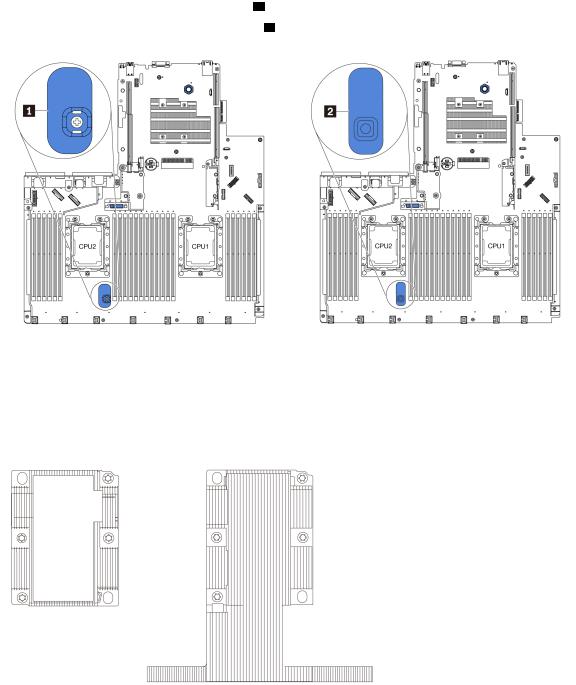
Important information for system board, processor, and heat sink
There are two types of system board for your server:
•Left: System board with large lift handle 1
•Right: System board with small lift handle 2
Figure 4. Two types of system board
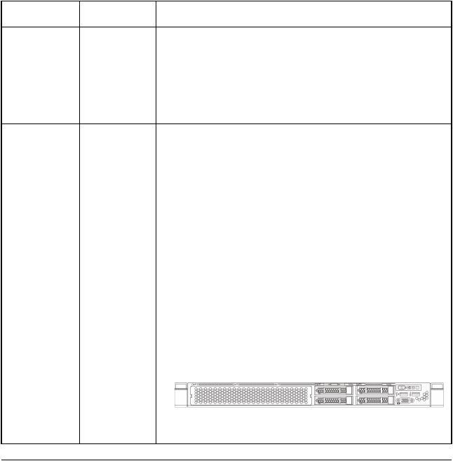
There are two shape types of heat sink for your server:
•Left: Small-size heat sink
•Right: Large-size heat sink
Figure 5. Two types of heat sink
8 ThinkSystem SR630 Maintenance Manual
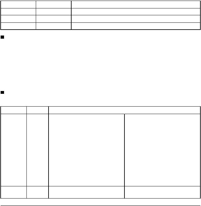
The following table lists the important information for the system board, heat sink, and processor.
System board |
Heat sink |
installed |
installed |
System board |
Small size heat |
with large lift |
sink |
handle or system |
|
board with small |
|
lift handle |
|
System board |
Large size heat |
with small lift |
sink |
handle |
|
Firmware updates
Important information
For server models installed with Intel Xeon 6144, 6146, 6154, 8168, 8180, and 8180M processors, the following parts are not supported:
•Front backplane and front hot-swap SAS/SATA/NVMe drives
•Rear hot-swap drive assembly
•RAID super capacitor module on the bottom of the air baffle
•NVMe PCIe flash adapter
•GPU
•For server models installed with large size heat sink, the air baffle and the RAID super capacitor module on the bottom of the air baffle are not supported.
•For server models installed with Intel Xeon 6144, 6146, 8168, 8180, and 8180M processors, ensure that the following configuration requirements are met:
–The backplane for ten 2.5-inch NVMe drives is not installed.
–No system fan is failed.
–Rear hot-swap drive assembly is not installed.
–NVMe PCIe flash adapter is not installed.
–GPU is not installed.
•For server models installed with the backplane for ten 2.5-inch SAS/ SATA/NVMe drives, Intel Xeon 6154 processor is supported with the condition that the following configuration requirements are met:
–No system fan is failed.
–Only four SAS/SATA/NVMe drives are installed in drive bays 6–9.
–Rear hot-swap drive assembly is not installed.
–NVMe PCIe flash adapter is not installed.
–GPU is not installed.
Figure 6. Front view of server models installed with Intel Xeon 6154 processor
Several options are available to update the firmware for the server.
You can use the tools listed here to update the most current firmware for your server and the devices that are installed in the server.
Note: Lenovo typically releases firmware in bundles called UpdateXpress System Packs (UXSPs). To ensure that all of the firmware updates are compatible, you should update all firmware at the same time. If you are updating firmware for both the Lenovo XClarity Controller and UEFI, update the firmware for Lenovo XClarity Controller first.
Chapter 1. Introduction 9

Best practices related to updating firmware is available at the following location:
http://lenovopress.com/LP0656
Important terminology
•In-band update The installation or update is performed using a tool or application within. an operating system that is executing on the server’s core CPU.
•Out-of-band update The installation or update is performed by the Lenovo XClarity Controller. collecting the update and then directing the update to the target subsystem or device. Out-of-band updates have no dependency on an operating system executing on the core CPU. However, most out-of-band operations do require the server to be in the S0 (Working) power state.
•On-Target update. The installation or update is initiated from an Operating System executing on the server’s operating system.
•Off-Target update. The installation or update is initiated from a computing device interacting directly with the server’s Lenovo XClarity Controller.
• UpdateXpress System Packs (UXSPs) UXSPs are bundled updates designed and tested to provide the |
. |
|||||||
interdependent level of functionality, performance, and compatibility. UXSPs are server machine-type |
|
|||||||
specific and are built (with firmware and device driver updates) to support specific Windows Server, Red |
|
|||||||
Hat Enterprise Linux (RHEL) and SUSE Linux Enterprise Server (SLES) operating system distributions. |
|
|||||||
Machine-type-specific firmware-only UXSPs are also available. |
|
|
|
|
||||
See the following table to determine the best Lenovo tool to use for installing and setting up the firmware: |
|
|||||||
|
|
Out-of- On- |
Off- |
Graphical |
|
|
|
|
|
In-band |
band |
target |
target |
user |
Command- |
Supports |
|
Tool |
update |
update |
update |
update |
interface |
line interface |
UXSPs |
|
Lenovo XClarity |
√ |
|
|
√ |
√ |
|
√ |
|
Provisioning |
|
|
|
|
|
|
|
|
Manager |
|
|
|
|
|
|
|
|
Limited to core system |
|
|
|
|
|
|
|
|
firmware only. |
|
|
|
|
|
|
|
|
Lenovo XClarity |
|
√ |
|
√ |
√ |
√ |
|
|
Controller |
|
|
|
|
|
|
|
|
Supports core system |
|
|
|
|
|
|
|
|
firmware and most |
|
|
|
|
|
|
|
|
advanced I/O option |
|
|
|
|
|
|
|
|
firmware updates |
|
|
|
|
|
|
|
|
Lenovo XClarity |
√ |
√ |
|
|
|
√ |
√ |
|
Essentials OneCLI |
|
|
|
|
|
|
|
|
Supports all core |
|
|
|
|
|
|
|
|
system firmware, I/O |
|
|
|
|
|
|
|
|
firmware, and installed |
|
|
|
|
|
|
|
|
operating system |
|
|
|
|
|
|
|
|
driver updates |
|
|
|
|
|
|
|
|
Lenovo XClarity |
√ |
√ |
|
|
√ |
|
√ |
|
Essentials |
|
|
|
|
|
|
|
|
UpdateXpress
Supports all core system firmware, I/O firmware, and installed operating system driver updates
10 ThinkSystem SR630 Maintenance Manual

|
|
Out-of- On- |
Off- |
Graphical |
|
|
|
|
In-band |
band |
target |
target |
user |
Command- |
Supports |
Tool |
update |
update |
update |
update |
interface |
line interface |
UXSPs |
Lenovo XClarity |
√ |
|
|
|
√ |
√ |
√ |
Essentials Bootable |
|
|
|
|
|
|
|
Media Creator |
|
|
|
|
|
|
|
Supports core system |
|
|
|
|
|
|
|
firmware and I/O |
|
|
|
|
|
|
|
firmware updates. You |
|
|
|
|
|
|
|
can update the |
|
|
|
|
|
|
|
Microsoft Windows |
|
|
|
|
|
|
|
operating system, but |
|
|
|
|
|
|
|
device drivers are not |
|
|
|
|
|
|
|
included on the |
|
|
|
|
|
|
|
bootable image |
|
|
|
|
|
|
|
Lenovo XClarity |
√ |
√ |
|
√ |
√ |
|
|
Administrator
Supports core system firmware and I/O firmware updates
The latest firmware can be found at the following site:
http://datacentersupport.lenovo.com/us/en/products/servers/thinksystem/sr630/7X01/downloads
•Lenovo XClarity Provisioning Manager
From Lenovo XClarity Provisioning Manager, you can update the Lenovo XClarity Controller firmware, the UEFI firmware, and the Lenovo XClarity Provisioning Manager software.
Note: By default, the Lenovo XClarity Provisioning Manager Graphical User Interface is displayed when you press F1. If you have changed that default to be the text-based system setup, you can bring up the Graphical User Interface from the text-based system setup interface.
Additional information about using Lenovo XClarity Provisioning Manager to update firmware is available at:
http://sysmgt.lenovofiles.com/help/topic/LXPM/platform_update.html
•Lenovo XClarity Controller
If you need to install a specific update, you can use the Lenovo XClarity Controller interface for a specific server.
Notes:
–To perform an in-band update through Windows or Linux, the operating system driver must be installed and the Ethernet-over-USB (sometimes called LAN over USB) interface must be enabled.
Additional information about configuring Ethernet over USB is available at:
http://sysmgt.lenovofiles.com/help/topic/com.lenovo.systems.management.xcc.doc/NN1ia_c_ configuringUSB.html
–If you update firmware through the Lenovo XClarity Controller, make sure that you have downloaded and installed the latest device drivers for the operating system that is running on the server.
Specific details about updating firmware using Lenovo XClarity Controller are available at:
http://sysmgt.lenovofiles.com/help/topic/com.lenovo.systems.management.xcc.doc/NN1ia_c_ manageserverfirmware.html
• Lenovo XClarity Essentials OneCLI
Chapter 1. Introduction 11
Lenovo XClarity Essentials OneCLI is a collection of command line applications that can be used to manage Lenovo servers.Its update application can be used to update firmware and device drivers for your servers. The update can be performed within the host operating system of the server (in-band) or remotely through the BMC of the server (out-of-band).
Specific details about updating firmware using Lenovo XClarity Essentials OneCLI is available at:
http://sysmgt.lenovofiles.com/help/topic/toolsctr_cli_lenovo/onecli_c_update.html
•Lenovo XClarity Essentials UpdateXpress
Lenovo XClarity Essentials UpdateXpress provides most of OneCLI update functions through a graphical user interface (GUI). It can be used to acquire and deploy UpdateXpress System Pack (UXSP) update packages and individual updates. UpdateXpress System Packs contain firmware and device driver updates for Microsoft Windows and for Linux.
You can obtain Lenovo XClarity Essentials UpdateXpress from the following location: https://datacentersupport.lenovo.com/solutions/lnvo-xpress
•Lenovo XClarity Essentials Bootable Media Creator
You can use Lenovo XClarity Essentials Bootable Media Creator to create bootable media that is suitable for applying firmware updates, running preboot diagnostics, and deploying Microsoft Windows operating systems.
You can obtain Lenovo XClarity Essentials BoMC from the following location: https://datacentersupport.lenovo.com/solutions/lnvo-bomc
•Lenovo XClarity Administrator
If you are managing multiple servers using the Lenovo XClarity Administrator, you can update firmware for all managed servers through that interface. Firmware management is simplified by assigning firmwarecompliance policies to managed endpoints. When you create and assign a compliance policy to managed endpoints, Lenovo XClarity Administrator monitors changes to the inventory for those endpoints and flags any endpoints that are out of compliance.
Specific details about updating firmware using Lenovo XClarity Administrator are available at: http://sysmgt.lenovofiles.com/help/topic/com.lenovo.lxca.doc/update_fw.html
Configuring the LAN over USB interface manually
To perform a firmware update through the operating system using Lenovo XClarity Essentials OneCLI, the Lenovo XClarity Controller must be configured to use the LAN over USB interface. The firmware update package attempts to perform the setup automatically, if needed. If the automatic setup fails or if you prefer to set up the LAN over USB manually, use one of the following procedures.
Additional information about using the Lenovo XClarity Controller to enable LAN over USB is available at:
http://sysmgt.lenovofiles.com/help/topic/com.lenovo.systems.management.xcc.doc/NN1ia_c_ configuringUSB.html
Installing the LAN over USB Windows device driver
When you install a Windows operating system, there might be an unknown RNDIS device in the Device Manager. Lenovo provides a Windows INF file that identifies this device.
Complete the following steps to install ibm_rndis_server_os.inf |
: |
Note: You only have to perform these steps if the compute node is running a Windows operating system and the ibm_rndis_server_os.inf file has not been previously installed. The file only has to be installed once. It
is required by Windows operating systems to detect and use the LAN over USB functionality.
12 ThinkSystem SR630 Maintenance Manual
Step 1. Click Administrative Tools Computer Management Device Manager and find the RNDIS |
|
|||
|
Device. Click Properties Driver Reinstall driver |
Point the server to the \Windows\inf |
. |
|
|
directory where it can find the ibm_rndis_server_os.inf file and install the device. |
|
|
|
Step 2. |
Click Administrative Tools Device Manager Right-click Network adapters and select Scan |
|
||
|
for hardware changes A small pop-up confirms that the Ethernet device is found and installed. |
. |
||
|
The New Hardware Wizard starts automatically. |
|
|
|
Step 3. |
When you are prompted Can Windows connect to Windows Update to search for software? select No, |
|
||
|
not this time Click Next to continue. |
. |
|
|
Step 4. |
When you are prompted What do you want the wizard to do? select Install from a list or specific, |
|
||
|
location (Advanced) Click Next to continue. |
|
|
|
Step 5. When you are prompted Please choose your search and installation options, select Don't search. I |
|
|||
|
will choose the driver to install Click Next to continue. |
. |
|
|
Step 6. |
When you are prompted Select a hardware type, and then click Next select Network, |
adapters |
|
|
|
Click Next to continue. |
|
|
|
Step 7. |
When you are prompted with the statement Completing the Found New Hardware Wizard click Finish |
|
||
|
A new local area connection appears. If the message This connection has limited or no |
|
||
|
connectivity is displayed, ignore this message. |
|
|
|
Step 8. Return to the Device Manager. Lenovo USB Remote NDIS Network Device appears under |
|
|||
|
Network Adapters |
|
|
. |
Step 9. Use the Lenovo XClarity Controller interface to view or set the IP address for the LAN adapter.
Additional information about using the Lenovo XClarity Controller to configure LAN over USB is available at:
http://sysmgt.lenovofiles.com/help/topic/com.lenovo.systems.management.xcc.doc/NN1ia_c_ configuringUSB.html
Tech Tips
Lenovo continually updates the support website with the latest tips and techniques that you can use to solve issues that you might have with your server. These Tech Tips (also called retain tips or service bulletins) provide procedures to work around issues related to the operation of your server.
To find the Tech Tips available for your server:
1.Go to http://datacentersupport.lenovo.com and navigate to the support page for your server.
2.Click How-tos & Solutions
Expand Symptom to choose a category for the type is problem that you are having.
Security advisories
Lenovo is committed to developing products and services that adhere to the highest security standards in order to protect our customers and their data. When potential vulnerabilities are reported, it is the responsibility of the Lenovo Product Security Incident Response Team (PSIRT) to investigate and provide information to our customers so they may put mitigation plans in place as we work toward providing solutions.
The list of current advisories is available at the following site:
https://datacentersupport.lenovo.com/product_security/home
Chapter 1. Introduction 13

Power on the server
After the server performs a short self-test (power status LED flashes quickly) when connected to input power, it enters a standby state (power status LED flashes once per second).
The server can be turned on (power LED on) in any of the following ways:
•You can press the power button.
•The server can restart automatically after a power interruption.
•The server can respond to remote power-on requests sent to the Lenovo XClarity Controller.
For information about powering off the server, see “Power off the server” on page 14.
Power off the server
The server remains in a standby state when it is connected to a power source, allowing the Lenovo XClarity Controller to respond to remote power-on requests. To remove all power from the server (power status LED off), you must disconnect all power cables.
To place the server in a standby state (power status LED flashes once per second):
Note: The Lenovo XClarity Controller can place the server in a standby state as an automatic response to a critical system failure.
•Start an orderly shutdown using the operating system (if supported by your operating system).
•Press the power button to start an orderly shutdown (if supported by your operating system).
•Press and hold the power button for more than 4 seconds to force a shutdown.
When in a standby state, the server can respond to remote power-on requests sent to the Lenovo XClarity Controller. For information about powering on the server, see “Power on the server” on page 14.
14 ThinkSystem SR630 Maintenance Manual

Chapter 2. Server components
Use the information in this section to learn about each of the components associated with your server.
Front view
The front view of the server varies by model. Depending on the model, your server might look slightly different from the illustrations in this topic.
Figure 7. Front view of server models with four 3.5-inch drive bays
Figure 8. Front view of server models with eight 2.5-inch drive bays
Figure 9. Front view of server models with ten 2.5-inch drive bays
Table 2. Components on the front of the server |
|
|
|
1 |
VGA connector (available on some models) |
2 |
Pull-out information tab |
3 |
XClarity Controller USB connector |
4 |
USB 3.0 connector |
5 |
Operator information panel |
6 |
Rack latch (right) |
© Copyright Lenovo 2017 |
15 |
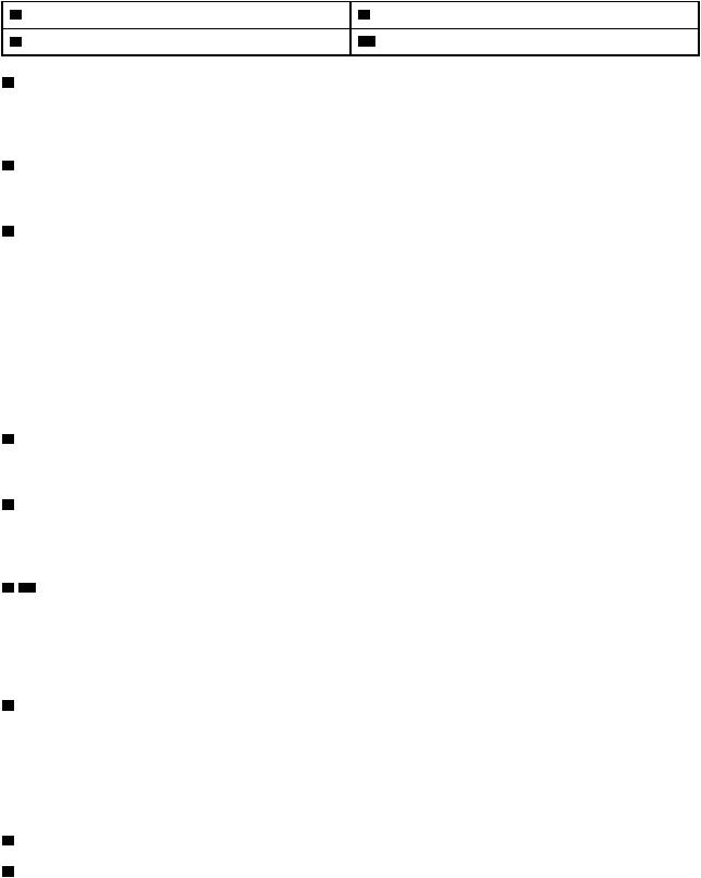
Table 2. Components on the front of the server (continued)
7 |
Hot-swap drive bays |
8 Drive status LED (yellow) |
9 |
Drive activity LED (green) |
10 Rack latch (left) |
1 VGA connector (available on some models)
Used to attach a high-performance monitor, a direct-drive monitor, or other devices that use a VGA connector.
2 Pull-out information tab
The XClarity Controller network access label is attached on the pull-out information tab.
3 XClarity Controller USB connector
Depending on the setting, this connector supports USB 2.0 function, XClarity Controller management function, or both.
•If the connector is set for USB 2.0 function, you can attach a device that requires a USB 2.0 connection, such as a keyboard, a mouse, or a USB storage device.
•If the connector is set for XClarity Controller management function, you can attach a mobile device installed with the application to run XClarity Controller event logs.
•If the connector is set to have both functions, you can press the ID button for three seconds to switch between the two functions.
4 USB 3.0 connector
Attach a USB-compatible device, such as a USB keyboard, USB mouse, or USB storage device.
5 Operator information panel
For information about the controls and status LEDs on the operator information panel, see “Operator information panel” on page 17.
6 10 Rack latches
If your server is installed in a rack, you can use the rack latches to help you slide the server out of the rack. You also can use the rack latches and screws to secure the server in the rack so that the server cannot slide out, especially in vibration-prone areas. For more information, refer to the Rack Installation Guide that comes with your rail kit.
7 Hot-swap drive bays
The number of the installed drives in your server varies by model. When you install drives, follow the order of the drive bay numbers.
The EMI integrity and cooling of the server are protected by having all drive bays occupied. The vacant drive bays must be occupied by drive fillers.
8Drive status LED
9Drive activity LED
Each hot-swap drive has two LEDs.
16 ThinkSystem SR630 Maintenance Manual
Drive LED |
Status |
Description |
|
8 |
Drive status LED (right) |
Solid yellow |
The drive has an error. |
|
|
Blinking yellow (blinking slowly, about one |
The drive is being rebuilt. |
|
|
flash per second) |
|
|
|
Blinking yellow (blinking rapidly, about four |
The RAID adapter is locating the drive. |
|
|
flashes per second) |
|
9 |
Drive activity LED (left) |
Solid green |
The drive is powered but not active. |
|
|
Blinking green |
The drive is active. |
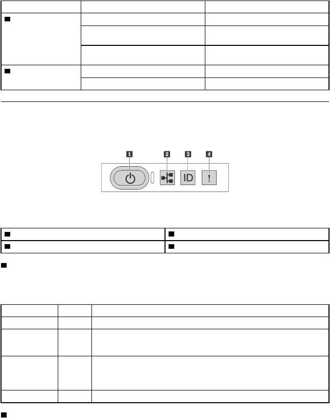
Operator information panel
The operator information panel of the server provides controls and LEDs.
The following illustration shows the operator information panel of the server.
Figure 10. Operator information panel |
|
|
|
Table 3. Components on the operator information panel |
|
|
|
1 |
Power button with power status LED |
2 |
Network activity LED |
3 |
System ID button with system ID LED |
4 |
System error LED |
1 Power button with power status LED
You can press the power button to power on the server when you finish setting up the server. You also can hold the power button for several seconds to power off the server if you cannot shut down the server from the operating system. The power status LED helps you to determine the current power status.
Status |
Color |
Description |
Solid on |
Green |
The server is on and running. |
Slow blinking |
Green |
The server is off and is ready to be powered on (standby state). |
(about one flash |
|
|
per second) |
|
|
Fast blinking |
Green |
The server is off, but the XClarity Controller is initializing, and the server is not ready |
(about four |
|
to be powered on. |
flashes per |
|
|
second) |
|
|
Off |
None |
There is no ac power applied to the server. |
2 Network activity LED
The network activity LED on the operator information panel helps you identify the network connectivity and activity.
Chapter 2. Server components 17
Status |
Color |
Description |
On |
Green |
The server is connected to a network. |
Blinking |
Green |
The network is connected and active. |
Off |
None |
The server is disconnected from the network. |
3 System ID button with system ID LED
Use this system ID button and the blue system ID LED to visually locate the server. A system ID LED is also located on the rear of the server. Each time you press the system ID button, the state of both the system ID LEDs changes. The LEDs can be changed to on, blinking, or off. You can also use the Lenovo XClarity Controller or a remote management program to change the state of the system ID LEDs to assist in visually locating the server among other servers.
If the XClarity Controller USB connector is set to have both the USB 2.0 function and XClarity Controller management function, you can press the system ID button for three seconds to switch between the two functions.
4 System error LED
The system error LED helps you to determine if there are any system errors.
Status |
Color |
Description |
On |
Yellow |
An error has been detected on the server. |
|
|
Causes might include but not limited to the |
|
|
following errors: |
|
|
• The temperature of the server reached |
|
|
the non-critical temperature threshold. |
|
|
• The voltage of the server reached the |
|
|
non-critical voltage threshold. |
|
|
• A fan has been detected to be running at |
|
|
low speed. |
|
|
• A hot-swap fan has been removed. |
|
|
• The power supply has a critical error. |
|
|
• The power supply is not connected to |
|
|
the power. |
Off |
None |
The server is off or the server is on and is |
|
|
working correctly. |
 Action
Check the event log to determine the exact cause of the error.
For information about troubleshooting, see “Troubleshooting by symptom” on page 156 .
None.
Rear view
The rear of the server provides access to several connectors and components, including the power supplies, PCIe adapters, hot-swap drive bays, serial port, and Ethernet connectors.
•“Rear view of server models with three PCIe slots” on page 18
•“Rear view of server models with two PCIe slots” on page 20
•“Rear view of server models with two hot-swap drive bays and one PCIe slot” on page 21
Rear view of server models with three PCIe slots
The following illustration shows the rear view of server models with three PCIe slots. Depending on the model, your server might look slightly different from the illustration below.
18 ThinkSystem SR630 Maintenance Manual
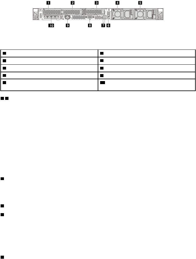
Figure 11. Rear view of server models with three PCIe slots |
|
|
|
Table 4. Components on the rear of the server |
|
|
|
1 |
PCIe slot 1 on riser 1 assembly |
2 |
PCIe slot 2 on riser 1 assembly |
3 |
PCIe slot 3 on riser 2 assembly |
4 |
Power supply 1 |
5 |
Power supply 2 (available on some models) |
6 |
NMI button |
7 |
USB 3.0 connectors |
8 |
VGA connector |
9 |
XClarity Controller network connector |
10 Ethernet connectors on LOM adapter (available on |
|
|
|
some models) |
|
1 2 PCIe slots on riser 1 assembly
Your server supports three types of riser cards for riser 1 assembly.
•Type 1
–Slot 1: PCIe x16 (x8, x4, x1), low-profile
–Slot 2: PCIe x16 (x16, x8, x4, x1), low-profile
•Type 2
–Slot 1: ML2 x8 (x8, x4, x1), low-profile
–Slot 2: PCIe x16 (x16, x8, x4, x1), low-profile
•Type 3
–Slot 1: ML2 x16 (x16, x8, x4, x1), low-profile
–Slot 2: PCIe x16 (x8, x4, x1), low-profile
3 PCIe slot on riser 2 assembly
Slot 3: PCIe x16 (x16, x8, x4, x1), low-profile
Note: PCIe slot 3 is supported only when two processors are installed.
4Power supply 1
5Power supply 2 (available on some models)
The hot-swap redundant power supplies help you avoid significant interruption to the operation of the system when a power supply fails. You can purchase a power supply option from Lenovo and install the power supply to provide power redundancy without turning off the server.
On each power supply, there are three status LEDs near the power cord connector. For information about the LEDs, see “Rear view LEDs” on page 24.
6 NMI button
Chapter 2. Server components 19
Press this button to force a nonmaskable interrupt (NMI) to the processor. By this way, you can make the operating system halt (such as Windows Blue Screen of Death) and take a memory dump. You might have to use a pen or the end of a straightened paper clip to press the button.
7 USB 3.0 connectors (2)
Used to attach a device that requires a USB 2.0 or 3.0 connection, such as a USB keyboard, USB mouse, or USB storage device.
8 VGA connector
Used to attach a high-performance monitor, a direct-drive monitor, or other devices that use a VGA connector.
9 XClarity Controller network connector
Used to attach an Ethernet cable to manage the system using XClarity Controller.
10 Ethernet connectors on LOM adapter (available on some models)
The LOM adapter provides two or four extra Ethernet connectors for network connections.
The leftmost Ethernet connector on the LOM adapter can be set as XClarity Controller network connector. To set the Ethernet connector as XClarity Controller network connector, start Setup utility, go to BMC Settings
Network Settings Network Interface Port and select Shared Then, go to Shared NIC on and select PHY Card .
Rear view of server models with two PCIe slots
The following illustration shows the rear view of the server models with two PCIe slots. Depending on the model, your server might look slightly different from the illustration below.
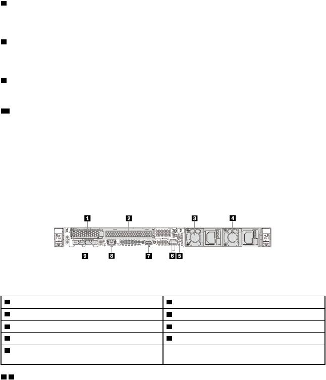
Figure 12. Rear view of server models with two PCIe slots |
|
|
|
Table 5. Components on the rear of the server |
|
|
|
1 |
PCIe slot 1 on riser 1 assembly |
2 |
PCIe slot 2 on riser 1 assembly |
3 |
Power supply 1 |
4 |
Power supply 2 (available on some models) |
5 |
NMI button |
6 |
USB 3.0 connectors |
7 |
VGA connector |
8 |
XClarity Controller network connector |
9 |
Ethernet connectors on LOM adapter (available on |
|
|
some models)
1 2 PCIe slots on riser 1 assembly
Your server supports three types of riser cards for riser 1 assembly.
• Type 1
20 ThinkSystem SR630 Maintenance Manual

–Slot 1: PCIe x16 (x8, x4, x1), low-profile
–Slot 2: PCIe x16 (x16, x8, x4, x1), full-height, half-length
•Type 2
–Slot 1: ML2 x8 (x8, x4, x1), low-profile
–Slot 2: PCIe x16 (x16, x8, x4, x1), full-height, half-length
•Type 3
–Slot 1: ML2 x16 (x16, x8, x4, x1), low-profile
–Slot 2: PCIe x16 (x8, x4, x1), full-height, half-length
3Power supply 1
4Power supply 2 (available on some models)
The hot-swap redundant power supplies help you avoid significant interruption to the operation of the system when a power supply fails. You can purchase a power supply option from Lenovo and install the power supply to provide power redundancy without turning off the server.
On each power supply, there are three status LEDs near the power cord connector. For information about the LEDs, see “Rear view LEDs” on page 24.
5 NMI button
Press this button to force a nonmaskable interrupt (NMI) to the processor. By this way, you can make the operating system halt (such as Windows Blue Screen of Death) and take a memory dump. You might have to use a pen or the end of a straightened paper clip to press the button.
6 USB 3.0 connectors (2)
Used to attach a device that requires a USB 2.0 or 3.0 connection, such as a USB keyboard, USB mouse, or USB storage device.
7 VGA connector
Used to attach a high-performance monitor, a direct-drive monitor, or other devices that use a VGA connector.
8 XClarity Controller network connector
Used to attach an Ethernet cable to manage the system using XClarity Controller.
9 Ethernet connectors on LOM adapter (available on some models)
The LOM adapter provides two or four extra Ethernet connectors for network connections.
The leftmost Ethernet connector on the LOM adapter can be set as XClarity Controller network connector. To set the Ethernet connector as XClarity Controller network connector, start Setup utility, go to BMC Settings
Network Settings Network Interface Port and select Shared Then, go to Shared NIC on and select PHY Card .
Rear view of server models with two hot-swap drive bays and one PCIe slot
The following illustration shows the rear view of the server models with two hot-swap drive bays and one PCIe slot. Depending on the model, your server might look slightly different from the illustration below.
Chapter 2. Server components 21
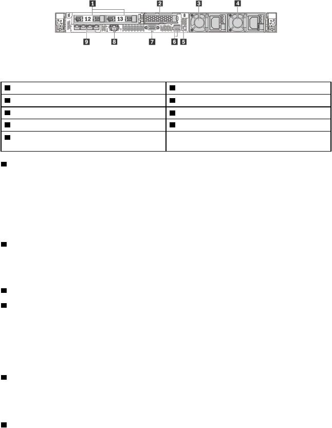
Figure 13. Rear view of server models with two hot-swap drive bays and one PCIe slot
Table 6. Components on the rear of the server |
|
|
|
1 |
Rear 2.5-inch drive bays |
2 |
PCIe slot 3 |
3 |
Power supply 1 |
4 |
Power supply 2 (available on some models) |
5 |
NMI button |
6 |
USB 3.0 connectors |
7 |
VGA connector |
8 |
XClarity Controller network connector |
9 |
Ethernet connectors on LOM adapter (available on |
|
|
some models)
1 Rear 2.5-inch drive bays
Used to install two 2.5-inch hot-swap drives on the rear of the server.
The number of the installed drives in your server varies by model. When you install drives, follow the order of the drive bay numbers.
The EMI integrity and cooling of the server are protected by having all drive bays occupied. The vacant drive bays must be occupied by drive bay fillers or drive fillers.
2 PCIe slot 3
Slot 3: PCIe x16 (x16, x8, x4, x1), low-profile
Note: PCIe slot 3 is supported only when two processors are installed.
3Power supply 1
4Power supply 2 (available on some models)
The hot-swap redundant power supplies help you avoid significant interruption to the operation of the system when a power supply fails. You can purchase a power supply option from Lenovo and install the power supply to provide power redundancy without turning off the server.
On each power supply, there are three status LEDs near the power cord connector. For information about the LEDs, see “Rear view LEDs” on page 24.
5 NMI button
Press this button to force a nonmaskable interrupt (NMI) to the processor. By this way, you can make the operating system halt (such as Windows Blue Screen of Death) and take a memory dump. You might have to use a pen or the end of a straightened paper clip to press the button.
6 USB 3.0 connectors (2)
Used to attach a device that requires a USB 2.0 or 3.0 connection, such as a USB keyboard, USB mouse, or USB storage device.
22 ThinkSystem SR630 Maintenance Manual
Loading...