

Page 1
University of Zurich
1
Center for Microscopy and Image Analysis
Leica SP5 Operating Manual
Table of contents
1. Starting procedure
1.1. Turing on the hardware…………………………………………………………2
1.2. Starting the software…………………………………………………………….2
2. Mounting and focusing of sample
2.1 The microscope…………………………………………………………………..3
2.2 Mounting of sample………………………………………………………………3
2.3 Selection of objective…………………………………………………………….3
2.4 Focusing of sample………………………………………………………………3
2.5 Illumination
2.5.1.Fluorescence……………………………………………………………….4
2.5.2. Bright field, Koehler illumination………………………………………... 4
3. Image acquisition in the confocal mode
3.1. Beam path settings……………………………………………………………5
3.2. Intensity adjustments……………………………………………………….…5
3.3. Set final scan parameters…………………………………………………….7
3.4. Execute experimet / save images……………………………………………8
3.5. Table image optimization……………………………………………………..8
4. Sequential scanning…………………………………………………………………….9
5. Acquiring a z-stack……………………………………………………………………. .9
6. Setting a timecourse…………………………………………………………………..10
7. Mark and Find / Tile Scan…………………………………………………………….10
8. APD……………………………………………………………………………………...10
9. Shutdown procedure…………………………………………………………………..10
10. Trouble shooting……………………………………………………………………….11
1
Page 2
University of Zurich
2
Center for Microscopy and Image Analysis
1. Starting procedure
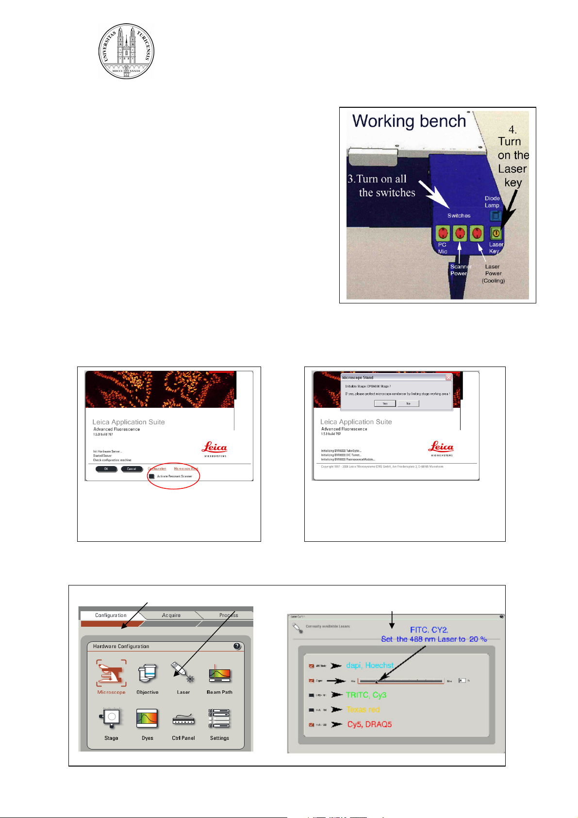
1.1. Turning on the hardware
1. Turn on the fluorescence lamp
2. Switch on all three switches on the panel
3. Turn on the laser key
4. Login the computer
(username: f.lastname; note: f corresponds
to first letter of first name. Initial password:
dummy)
1.2. Starting the software
Klick twice into the icon “LAS AF”
The following windows appear
Select whether the system
should be operated in the
resonant or non-resonant mode.
Click on OK..
After the hardware is initialized, switch on the lasers in the software:
1. Klick into Configuration 2. Klick into Laser 3. Activate the lasers you require
.
Decide whether the table needs to
be initialized. Only necessary if you
need to define positions on the
stage.
2
Page 3
University of Zurich
3
Center for Microscopy and Image Analysis
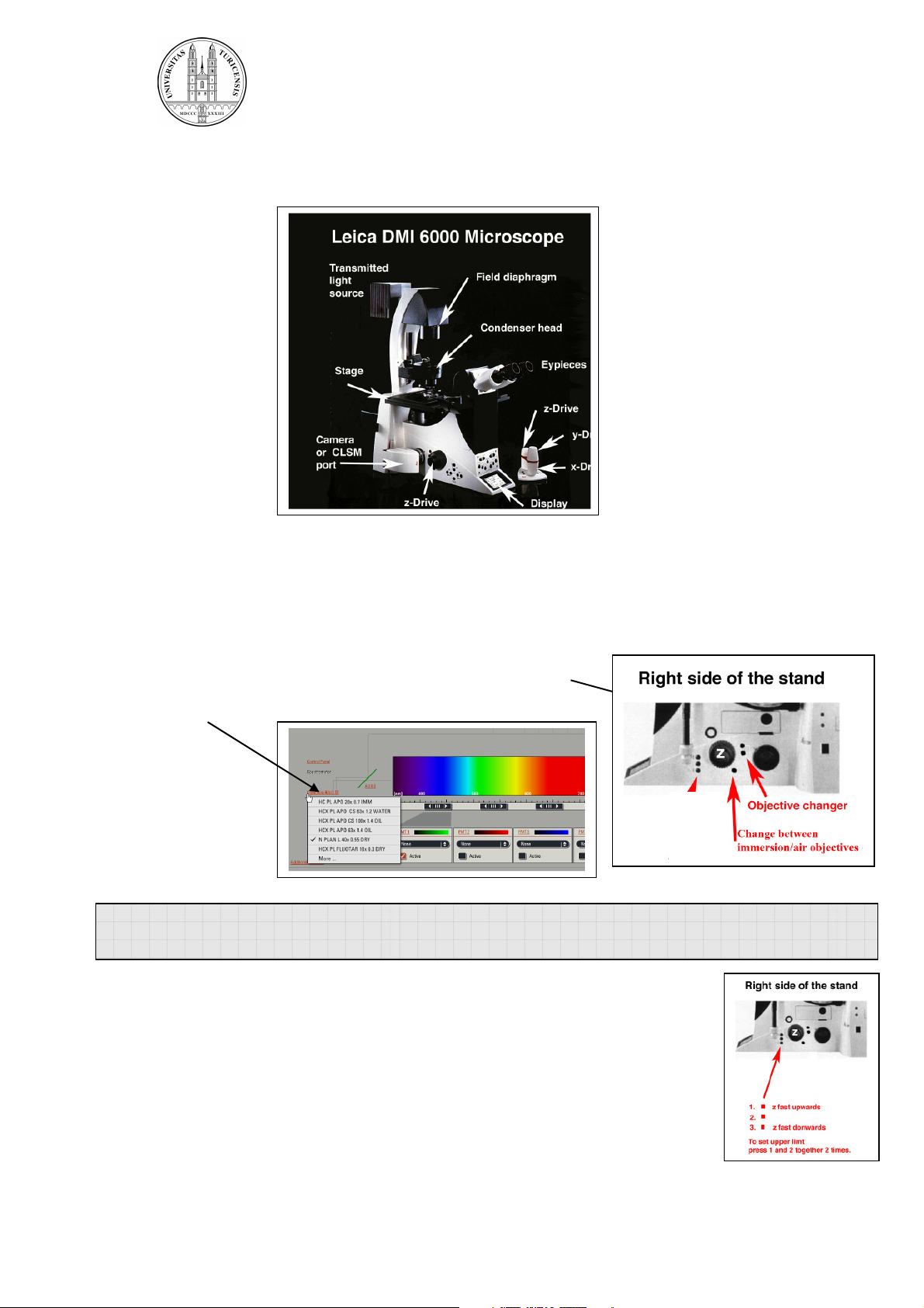
2. Mount and focus sample
The microscope:
2.1. Mounting of sample:
Put the slide up-side-down on the stage. If you are using immersion objectives, make
sure you use the appropriate immersion medium and never mix different media. Add
a drop to the objective or coverslip.
2.2. Selection of objective:
Select the objective directly on the scope by pressing the
objective changer buttons or more conveniently by the
software.
.
Note: Check objectives for the proper adjustment of correction collars and make sure
that the cap on the front of the objective is released.
2.3. Focusing your sample:
Start with the 10 x air objective to find the focus and to get an overview
of your sample. Focus your sample by moving the objective up with the
focus wheel or button on the microscope or with the z-drive on the
controller unit. Start in the coarse focus mode and fine tune with the fine
focus mode (toggle button on the controller unit).
Fix the focal plane:
To save your focal plane press button 1 and 2 (see illustration above) on
the right side of the stand together twice. The Z-position is now on 0.
Controller unit
3
Page 4
University of Zurich
4
Center for Microscopy and Image Analysis
If you change than to another lens you just have to fine tune the focal plane.
Note: Always start with a low magnifying air objective. Be careful when working with
immersion lenses to not run into the sample.
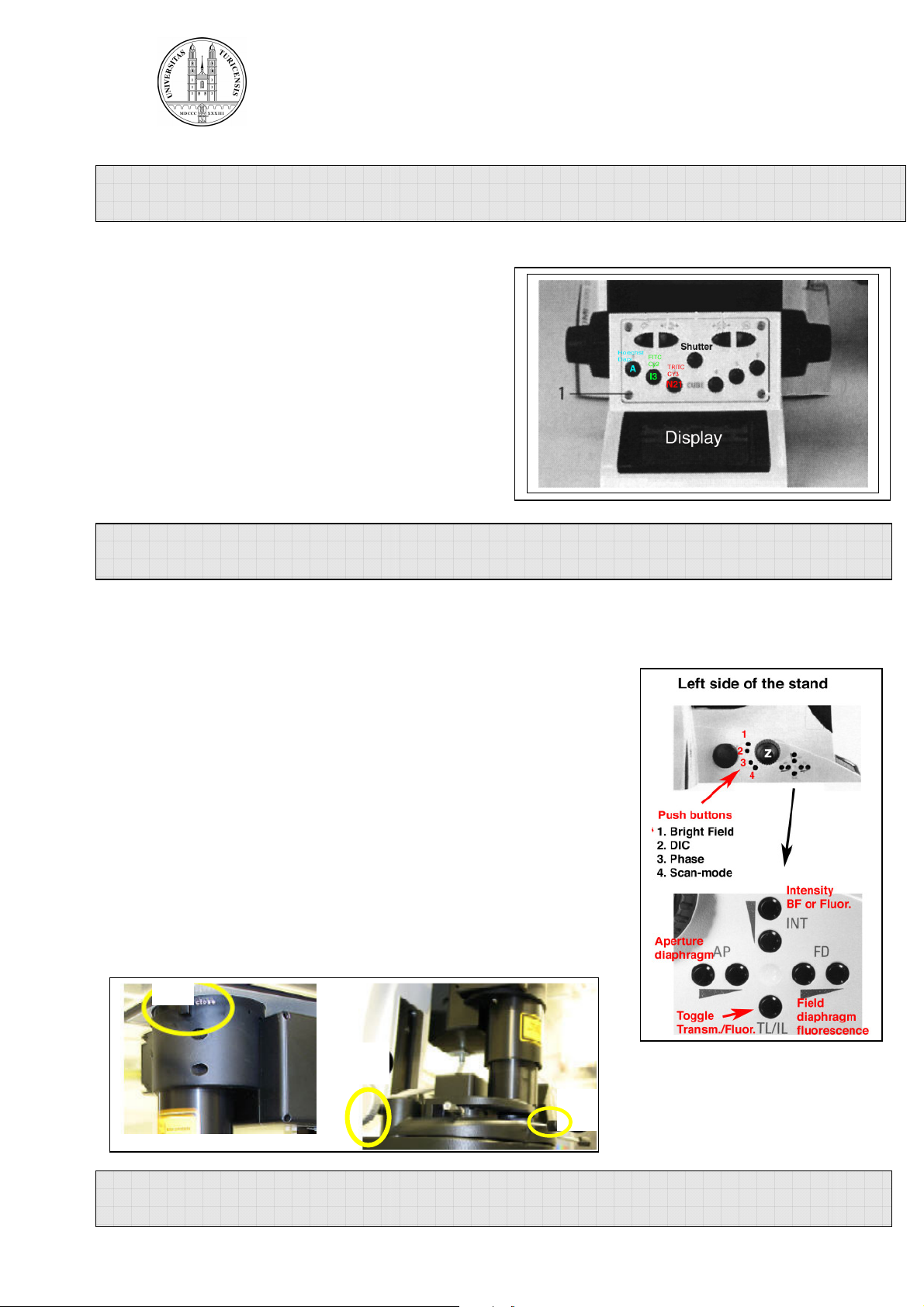
2.4. Illumination:
Fluorescence:
Choose a filter by pressing the appropriate filter
button on the front of the stand.
Open the shutter.
Adjust the power of the fluorescence lamp by the
INT button on the left side of the stand
(see illustration below) or directly on the
fluorescence lamp.
Note: To avoid photobleaching work with an intensity as low as possible and close
the shutter when you stop observing your sample.
Bright field:
Choose bright field light by pressing the corresponding button
on the left side of the stand (BF, DIC, Phasecontrast).
Adjust the brightness with the INT button on the left side of the
stand or at the fluorescence lamp.
For DIC adjust the aperture diaphragm (AP) and Wollaston
Shear Control (wheel on objective turret) for optimal contrast.
For recording of bright field images adjust for
“Koehler illumination”:
1. focus specimen
2. fully close the illumination iris
3. focus condenser until diaphragm edge is in focus
4. move the illumination iris to the center with the 2 screws
5. open up illumination iris until it just fills the field of view
Note: It is always worthwhile to observe your cells in bright field mode to check
whether they are healthy.
3
4
4
Page 5

University of Zurich
5
Center for Microscopy and Image Analysis
3. Image acquisition in the confocal mode
3.1.Beam path settings
Leica presettings or your own saved configurations for a particular fluorochrome or
fluorochrome-combination can be loaded (Note: settings for different microscopes
are not exchangeable!).
You can also make the settings step by step:
1. Select laser lines: Activate the laser
lines according to your fluorochromes. Start
with a laser intensity around 20 %.
2. Activate the PMT’s you need.
3. Visualize the reference emission curves of
your fluorochromes in order to get an idea
where to detect your signals. Check for
overlapping spectras of different
fluorochromes.
4. Choose a pseudocolor for each channel.
5.Set the detection bandwith. Make sure that
the edges of the detection window are at least
10 nm apart from the excitation lines.
Note: Check for crosstalk if you have multilabeled specimen with overlapping
spectras. Fluorochromes with strongly overlapping emission spectras are best
detected sequentially (see under 4.).
3.2. Intensity adjustment
The intensity of the image can be controlled by the laser intensity and the gain
(amplification of photons) and offset (threshold) adjustment of the detector.
1. Start preview scanning by clicking on LIVE.
2. Enhance the gain until you see an image. By default the gain in on 0V
(black screen) when you start.
Adjust the focal plane with the z-knob until you see the brightest plane
of interest.
3. Adjust gain and offset:
To aid adjustment of gain and offset choose the “glow-over-under”
display by clicking into the QLut icon (left border on right screen).
5
Page 6

University of Zurich
6
Center for Microscopy and Image Analysis
In this display mode the the saturated pixels (grey level 256) are represented by
blue dots and the black signals (grey level 0) are shown in green.
0 51 102 153 204 2550 51 102 153 204 255
While scanning adjust the offset and gain so that there are a few green pixel in
the background and some blue speckles in the object. The aim is to have the
whole range of grey levels in the image.
Note: .Enhancement of gain will increase noise. Do not exeed the maximal setting of
1000 V or in low signal cases 1250 V.
4. Adjust laser intensity.
Note: Always work with the lowest laser intensity possible to avoid photobleaching
and phototoxicity.
5. Save your settings:
You can save and reload your configurations
of laser intensity, detection bandwith, gain and
offset (Settings can only be used on the microscope
they were saved due to changing hardware
configuration).
6
Page 7

University of Zurich
7
Center for Microscopy and Image Analysis
3.3. Set final scan parameters
Acquisition mode
For fixed samples normally scanning in xyz is selected.
Other scan modes are xzy (front view), yzx (side view)
xyt (time course) and xyλ (spectral imaging) .
XY panel settings:
Frame size:
Usually at 512 x 512.
If a better digital resolution is needed a higher format
can be choosen.By enhancing the format the pixel size
decreases. To match the digital with the optical resolution
choose the pixel size according to the Nyquist criterion
(see below under zoom).
But note: A higher format increases the acquisition time
and hence the bleaching. Furthermore the double format
multiplies the data size by a factor of 4!
Speed:
Most commonly the scanning speed is set to 400 Hz
(lines scanned/sec.).
Note: The Signal to Noise ratio can be increased by a slower scan rate (for low
intensity signals). But a slower scan rate increases bleaching.
Pinhole:
The optimal opening of 1Airy is automatically adjusted by the software according to
the objective used.
Note: The pinhole can be opend up for dim signals, but optical section thickness will
be compromised.
Zoom:
By zooming in detail view and resolution can be enhanced.
There are two ways to zoom in:
Choose a constant zoom by increasing the zoom factor
or select Zoom in and define a rectangular ROI
( icon left side of the right screen) for the area you want to acquire.
By zooming in the pixel size will decrease. For high resolution imaging optimal
pixel size according to the Nyquist criterion should be ensured. The Nyquist
criterion states that the smallest detail which can be resolved by the optics should
be represented by 2.3 pixels. Note that the pixel size can also be decreased by
enhancing the format.
:
:
7
Page 8

University of Zurich
8
Center for Microscopy and Image Analysis
Objective Optimal pixel size (nm) with 488 nm laser
63-er Oil / N.A. 1.4 60 nm
63-er Glycerol / N.A. 1.3 65 nm
40 –er Oil / N.A. 1.25 68 nm
20-er multi-immersion/ N.A. 0.7 120 nm
Pixel smaller than the optimal will result in oversampling, increased bleaching,
increased noise and no extra spatial information. Pixel larger than the optimal
will result in lower spatial resolution than given by the optics.
Note: Increasing the zoom decreases the area scanned and increases the rate of
photobleaching.
Averaging:
A way to improve the signal to noise ratio is to sample
and average each pixel a number of times.
Line averaging: for live imaging.
Line or frame averaging: for fixed cells.
(Often an averaging of 4 to 8 is choosen)
Accumulation: For weak signals the intensities can be accumulated. Combine with
line averaging.
Note: Averaging also increases the acquisition time and bleaching.
3.4 . Execute experiment / save images
To acquire a single XY image click the Capture image button. For acquiring a
sequence of images (sequential scan, z-stack, time-series) click the Start button.
Your data will be listed under Experiments but will not automatically be saved. To
save the image click on Save all. Saving your data in the (*.LIF) format (Leica
proprietary format) is strongly advised to be able later to restore the acquisition
parameters. Images in the *.LIF format can be read by image processing softwares
like ImageJ or Imaris. However, it is also possible to export all the images in the
format of your choice (TIFF, JPEG) by right clicking into the Experiment or single
images.
3.5 Table: image optimization
Zoom + - + -
Format + - + -
Speed - + - +
Averaging + - + -
Pinhole + - - + - +
+ enhancement; - decrease
Signal to noise
ratio /Image quality
Resolution Bleaching
8
Page 9

University of Zurich
9
Center for Microscopy and Image Analysis
4. Sequential scanning
To minimize cross-talk between different fluorochromes each channel can be
acquired in sequence. Click the seq button in the Acquisition mode window.
The sequential control panel appears now at the bottom.
Configure the sequences:
Select first channel as scan 1 and define the settings. Add (+) scan 2 and make the
settings for this second channel and so one for further channels. Select in what mode
the scanning should be performed.
Between lines: Only the settings of the laser lines are changed. The detection
ranges must not overlap and are not adjusted between lines. Quickest method,
lowest movement artifacts.
Between frames: Maximal cross-talk prevention, complete changing of settings
between channels, movement artifacts possible.
Between stacks: Speeds acquisition of z-stacks but might lead to movement
artifacts and z- aberrations between channels.
The sequential settings can be saved and reloaded.
5. Acquiring a Z-stack
Activate the Z-stack window. The cube represents the specimen. The yellow plane
marks the current z-position. This position is specified in the field below the cube (zposition µm).
1. Set the z-stack range: Select the top and the
bottom of the sample and define them by clicking into the
Begin and End arrow which will than turn red.
2.Set z-step size: By default the software calculates the
optimal z-step size and number or steps (accept this
frequency for subsequent deconvolution or 3-D
reconstruction) . However, often such a high z-imaging
frequency is not necessary. You can also define the
number of images of a z-stack and the distance between
them manually.
Note: Do not forget to set back the step Nr. to 1 if you don’t want to record stacks
anymore.
9
Page 10

University of Zurich
10
Center for Microscopy and Image Analysis
6. Setting a timecourse
In the Acquisition mode window select the xyz option. This will open the time
course window which is fairly self explanatory. Insert the settings for the time interval
and duration. Minimize will set the time interval to as fast as possible.
7. Mark and Find and Tile Scan
The Mark and Find tool enables you to mark various position in x, y and z on the
stage. At this positions you can define image stacks with different settings.
The Tile Scan function allows to scan multiple images of a scan field and stich them
to a complete image. This function allows you to scan high resolution overviews.
For detailed information about this two features consult the help dialog of the Leica
software.
8. APD (Avalanche Photodiode Detector)
For very dim or sensitive specimen it is possible to use an external APD for highest
signal to noise ratio, single molecule detection but, currently, detection of emission
520 nm and emission 590nm are only possible. Note that this detector is slow. Ask
the staff of the ZMB for further information and instruction.
9. Shutdown procedure
1. Save your images on the “H” drive, turn off the lasers in the software, quit
software and logoff.
2. Clean the objective if you used immersion media. Moisten a soft tissue with
ethanol for cleaning oil, with distilled water for glycerol or residues of embedding
media. Clean first the metal body and than sweep gently over the
lens with a new tissue moistened with the cleaning solution.
3. Check on the online Reservation System AUL (Link reservation on
www.zmb.uzh.ch) if somebody uses the microscope after you.
4. If yes: you can leave the microscope like this.
5. If no:
• - Turn off the Laser Key
• - Shut down the computer
• - Switch off the fluorescence lamp
• - Switch off the buttons 1(PC/Mic) and 2 (Scanner) on the panel
• - Wait
for 5 min unless you switch off the laser button on the panel
10
Page 11

University of Zurich
11
Center for Microscopy and Image Analysis
10. Trouble shooting
No signals are detected on the screen:
Check if the lasers are on and that the detector is selected. Check that the gain is
above zero (usually the gain needs to be around 700 – 1000 volts, but the default
setting is zero).
The sample can not be focused or the image appears blurred:
Check if you have enough immersion fluid. If this is not the problem check if the
lens is clean. Check for the right coverglass thickness (0.17 mm!) if you are working
with oil immersion lenses.
Error message / freezing of software:
1. Note the error in the confocal logbook.
2. If possible save your experiment then close the software. If the software
crashed you may need to force quite by the “Task manager” (simultaneously
press “Ctrl” “Alt” and “Delete” on the keyboard and select “End Process” for
“LAS AF” and “LCS”).
3. Turn off the “Scanner button” at the control panel. Switch the scanner on again
after a couple of seconds.
4. Restart the software.
If the problem persists:
Completely restart the computer, microscope and scanner:
1. Close the software.
2. Shutdown the computer.
3. Turn off the “Scanner” and the “PC & Microscope” button at the control panel.
(it is normally not necessary to restart the lasers!)
4. Wait a couple of minutes then restart everything as per normal startup
procedure.
If this did not help contact the staff of the ZMB: 55218 (Irchel) or 42 601
(Gloriastrasse).
11
 Loading...