

Page 1
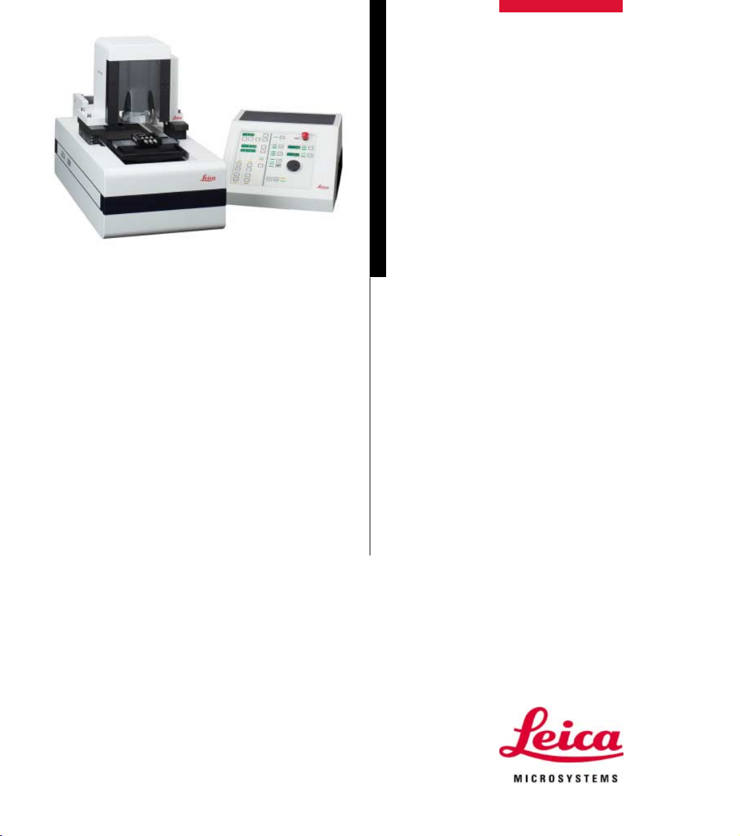
Supplementary instruction manual Leica SP2600
To be used only in conjunction
with instruction manual Leica SM2500 .
V1.2 English 07/2002
Always keep this manual near the instrument.
Read carefully prior to operating the instrument.
Leica SP2600
Ultramilling attachment
Page 2

Page 3

NOTE
The information, numerical data, notes and value
judgments contained in this manual represent the
current state of scientific knowledge and stateof-the-art technology as we understand it following thorough investigation in this field.
We are under no obligation to update the present
manual according to the latest technical developments, nor to provide our customers with additional copies, updates etc. of this manual.
For erroneous statements, drawings, technical
illustrations etc. contained in this manual we exclude liability as far as permissible according to
the national legal system applicable in each individual case. In particular, no liability whatsoever
is accepted for any financial loss or consequential damage caused by or related to compliance
with statements or other information in this manual.
Statements, drawings, illustrations and other information as regards contents or technical details of the present manual are not to be considered as warranted characteristics of our
products.
These are determined only by the contract provisions agreed between ourselves and our customers.
Leica reserves the right to change technical
specifications as well as manufacturing processes without prior notice. Only in this way is it possible to continuously improve the technology and
manufacturing techniques used in our products.
This document is protected under copyright laws.
Any copyrights of this document are retained by
Leica Microsystems Nussloch GmbH.
Any reproduction of text and illustrations (or of
any parts thereof) by means of print, photocopy,
microfiche, web cam or other methods including any electronic systems and media requires
express prior permission in writing by Leica Microsystems Nussloch GmbH.
For the instrument serial number and year of
manufacture, please refer to the name plate at
the back of the instrument.
© Leica Microsystems Nussloch GmbH
Published by:
Leica Microsystems Nussloch GmbH
Heidelberger Str. 17 - 19
D-69226 Nussloch
Germany
Telephone: +49 (0)6224 143-0
Facsimile: +49 (0)6224 143-200
Internet: http://www.histo-solutions.com
Leica SP2600 Ultramilling attachment
3
Page 4

Table of contents
1. Important information................................................................................................................6
1.1 Symbols in the text and their meaning ................................................................................................ 6
1.2 Designated use........................................................................................................................................ 6
1.3 Information on this instruction manual................................................................................................ 7
2. Safety ............................................................................................................................................ 8
2.1 Safety regulations ................................................................................................................................... 8
2.2 Built-in safety devices............................................................................................................................ 9
2.3 Safety instructions ................................................................................................................................ 10
3. Technical Data ......................................................................................................................... 13
4. Installation................................................................................................................................. 14
4.1 Overview - Leica SP2600 Ultramilling attachment / basic instrument Leica SM2500
- instrument parts / functions .............................................................................................................. 14
4.2 Leica SP2600 standard delivery.......................................................................................................... 15
4.3 Site requirements.................................................................................................................................. 15
4.4 Unpacking, transport, installation ...................................................................................................... 15
4.5 Installing the Leica SP2600 ultramilling attachment........................................................................ 16
4.6 Connecting the vacuum cleaner......................................................................................................... 17
4.7 Installing additional accessories........................................................................................................ 18
5. Operation ..................................................................................................................................... 19
5.1 Overview of chapter 5 Operation...................................................................................................... 19
5.2 Adjusting the pre-millers in the calibrating device..........................................................................20
5.3 Adjusting the finishing millers in the calibrating device ................................................................. 25
5.4 Specimen holder systems - how to combine individual components .......................................... 29
5.5 Clamping specimen .............................................................................................................................. 30
5.5.1 Installing the base plates in the basic instrument ........................................................................... 30
5.5.2 Clamping the specimen holders in the base plate with dove tail guide ....................................... 30
5.5.3 Clamping the vacuum stages on/in the base plates........................................................................ 31
5.5.4 Connecting the vacuum pump / placing specimens onto the vacuum stages ............................ 32
5.6 Preparatory steps prior to the milling procedure ............................................................................ 34
5.7 Pre-milling .............................................................................................................................................. 36
5.7.1 Perspective view of the pre-milling procedure................................................................................ 38
5.8 Finishing milling ..................................................................................................................................... 40
5.8.1 Perspective view of the finishing milling procedure ....................................................................... 42
5.9 Switching the instrument off (switching off the control unit .......................................................... 43
4
Supplementary instruction manual V 1.2 07/2002
Page 5

Important information
6. Troubleshooting ....................................................................................................................... 44
7. Cleaning, disinfection and maintenance ............................................................................ 45
7.1 Cleaning and disinfection .................................................................................................................... 45
7.2 Maintenance.......................................................................................................................................... 46
7.2.1 Resharpening the millers ..................................................................................................................... 46
7.2.2 Replacing the light bulb in the calibration device............................................................................ 47
8. Overview - accessories .......................................................................................................... 48
8.1 Miller holders and millers .................................................................................................................... 48
8.2 Base plates for specimen holders and vacuum stage adapters ................................................... 48
8.3 Specimen holders ................................................................................................................................. 48
8.4 Vacuum stage adapters ....................................................................................................................... 48
8.5 Vacuum stages and matching lids / perforated specimen holders .............................................. 49
8.6 Vacuum pumps ...................................................................................................................................... 49
8.7 Additional accessories ........................................................................................................................ 50
9. Warranty and service ................................................................................................................ 51
Leica SP 2600 Ultramilling attachment
5
Page 6
1. Important information
1.1 Symbols in the text and their meaning
Warnings and cautions appear in a
grey box and are marked by a warning
triangle.
Failure to comply with these warnings/
cautions can lead to accidents, bodily
injury and damage to instrument and/
or accessories.
Notes, i.e. important information for the
user, appear in a grey box and are
marked by an information sign.
Figures in brackets refer to item num-
(5)
bers in illustrations or to the illustrations themselves.
1.2 Designated use
Fig. 1.1
The Leica SP2600 is designated to prepare milled
surfaces and thin slices of specimen materials
such as plastics and metals as well as of organic
materials (such as bones, teeth) in medicine, biology and industry.
The Leica SP2600 ultramilling attachment is an
accessory which cannot be operated as a standalone device but must be used in conjunction
with the Leica SM2500 sliding microtome described in a separate instruction manual.
ENTER
6
Function keys that need to be pressed
Fig. 5.23
on the control unit are printed in bold
and capital letters.
Specimen surfaces are milled with a rotating
spindle, equipped with either a pre- or a finishing
miller.
With each sledge stroke, the micrometer feed
mechanism of the Leica SM2500 lowers the miller towards the specimen by the feed setting selected.
The Leica SP2600 may be used only in conjunction with accessories and supplementary instruments made by Leica.
If the instrument is used for any other than
the designated application, this will be
considered an improper use of the product!
Supplementary instruction manual V 1.2 07/2002
Page 7
1.3 Information on this instruction manual
Instrument type
This supplementary instruction manual must be used together with the Leica
SM2500 sliding microtome instruction manual describing the basic instrument Leica SM2500, which is needed to operate the Leica SP2600 ultramilling attachment.
All information provided in this supplementary instruction manual applies
only to the instrument type indicated on the title page.
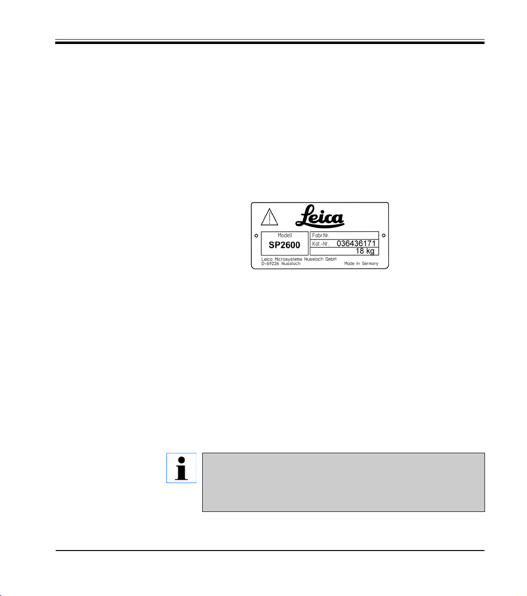
A name plate indicating the instrument type and serial number is attached to
the rear of the Leica SP2600 ultramilling device.
Fig. 1.2
Working with this instruction manual
This supplementary instruction manual contains important instructions and
information related to the operating safety and maintenance of the Leica
SP2600 ultramilling attachment.
It is an important part of the Leica SP2600 ultramilling attachment.
Prior to setting up and operating the Leica SP2600 together with the Leica
SM2500 be sure to read carefully both this supplementary instruction
manual as well as the Leica SM2500 instruction manual, with the exception
of chapters 5.5.6 - 5.7 of the Leica SM2500 manual. These chapters describe
installation of knife holders / knives and sectioning with the Leica SM2500
and are not of importance for operating the Leica SP2600 ultramilling attachment.
1. Important information
Leica SP 2600 Ultramilling attachment
If additional requirements on accident prevention and environmental protection exist in the country of operation, this supplementary
instruction manual must be supplemented by additional appropriate instructions to ensure compliance with such requirements.
7
Page 8

2. Safety
2.1 Safety regulations
This instrument has been built and tested in accordance with the same directives and standards as the Leica SM2500.
For a complete list of the directives and standards applied please refer to
chapter 2.1, page 8 of the Leica SM2500 instruction manual.
In order to maintain the SP2600 in a condition compliant with the above directives and standards and to ensure safe operation, the operator must observe the instructions and warnings contained in this supplementary instruction manual as well as in the Leica SM2500 instruction manual.
The Leica SP2600 ultramilling may be operated only in conjunction
with the Leica SM2500 sliding microtome!
8
Supplementary instruction manual V 1.2 07/2002
Page 9
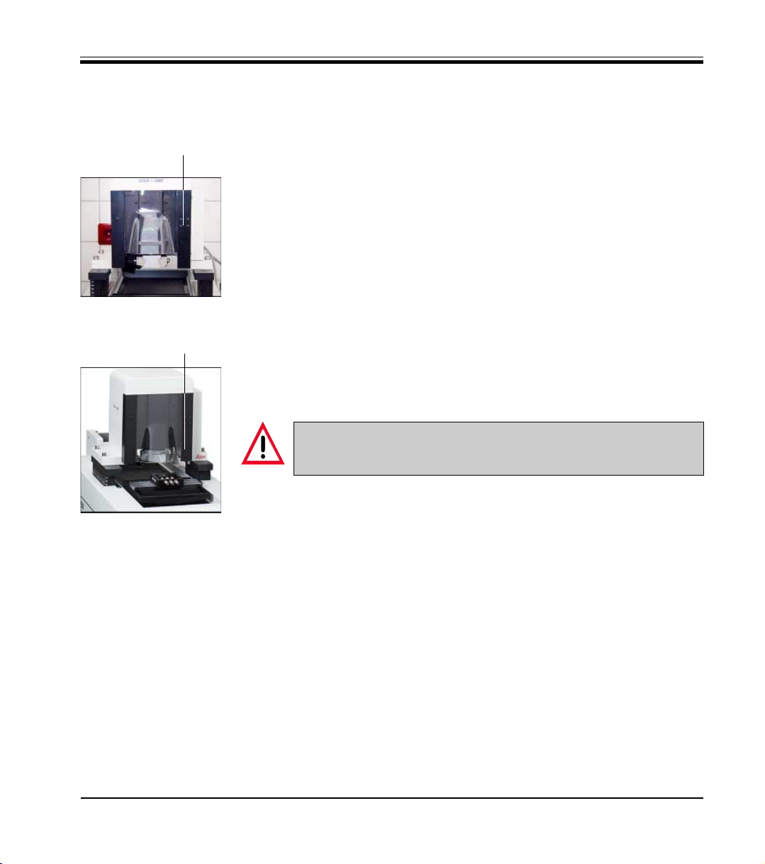
2.2 Built-in safety devices
The instrument is equipped with the following safety devices:
1
Plexiglass protective cover
The miller is equipped with a protective cover made of plexiglass (1).
When the cover is moved to the upper limit position (1, Fig. 2.1) the miller
is automatically blocked and cannot be started.
For any manipulations in the milling area (such as inserting millers, fine
adjustment of specimen height etc.) the protective cover (1, Fig. 2.1) must
be in the upper limit position.
Fig. 2.1
1
To be able to start the miller, the protective cover must be lowered (1,
Fig. 2.2).
2. Safety
Never touch the milling spindle while the plexiglass cover is shut,
no matter whether the spindle is rotating or not.
Fig. 2.2
Important note on the safety devices built in by the manufacturer:
The safety devices provided by the manufacturer constitute only a basis for
accident prevention.
Major responsibility for accident prevention during the use of the instrument
rests with the employer who has the operating authority for the instrument
and, in addition, with the persons, designated by him, who operate, service
and repair the instrument.
To ensure safe and trouble-free operation of the instrument, be sure to
comply with all instructions, warning and cautions in this supplementary
instruction manual as well as in the Leica SM2500 instruction manual!
Leica SP 2600 Ultramilling attachment
9
Page 10
2. Safety
2.3 Safety instructions
Be sure to read and comply with the
safety instructions, warnings and cautions in this chapter as well as in
chapter 2 of the Leica SM2500 instruction manual, even if you are already familiar with the operation and use of
other Leica products.
Safety instructions - general
The Leica SP2600 ultramilling attachment may only be operated in conjunction with the Leica SM2500 sliding microtome.
Prior to working with the Leica SP2600
ultramilling attachment, be sure to
read the following instruction manuals:
The entire Leica SM2500 instruction
manual except chapters 5.5.6
through 5.7.
This supplementary instruction
manual Leica SP2600.
The Leica SP2600 ultramilling attachment may only be operated by skilled
laboratory personnel. It may only be
used for the designated application
and operated in accordance with the
instructions contained in this supplementary instruction manual and in the
Leica SM2500 instruction manual!
Safety instructions - transport and installation
Be sure to follow the unpacking instructions (attached to the outside of
the instrument shipping crate)!
Never remove or modify any of the
safety devices installed on the instrument and/or accessories!
Before mounting the ultramilling attachment, make sure the bearing
blocks of the microtome supporting the
milling attachment and the bearing
surfaces of the milling attachment are
clean.
Two people are required to place the
milling attachment on the bearing
blocks from above.
Do not slide the milling attachment
onto the bearing blocks to prevent the
bearing surfaces of the microtome and
milling attachment from getting
scratched!
The bearing surfaces must not become
damaged under any circumstances!
Caution:
When releasing the lid of the milling
attachment (can be lifted and used as
a handle) be careful not to get your fingers caught between the lid and the
body of the milling attachment!
10
Supplementary instruction manual V 1.2 07/2002
Page 11
2. Safety
Safety instructions - transport and installation
Caution!
Only the vacuum cleaner offered by
Leica or other vacuum cleaner brands
rated at 230 V/ 50 Hz and a maximum
power draw of 4 A can be connected
directly to the SM2500 control unit (see
page 17), and this only in countries
where the mains supply is 230 V / 50
Hz!
Otherwise, the vacuum cleaner must
be connected directly to mains and operated via the on/off switch of the
vacuum cleaner.
Safety instructions - inserting the millers into the
holders / working with the calibrating device
Twisted or deformed springs for the
miller holders must be exchanged!
When the millers are inserted into the
holders the letter V (pre-millers) or F
(finishing miller) must be visible for the
milling edge to point into the right direction.
Caution:
The gauge contact plate must never hit
the milling edge.
This could damage the surface of the
contact plate, leading to incorrect
measuring results.
Be very careful when drawing the contact plate close to the milling edge.
Always use the magnifier.
Safety instructions working with the instrument
Never remove or modify any of the
safety devices installed on the instrument and/or accessories!
Never touch the milling spindle while
the plexiglass cover is shut, no matter
whether the spindle is rotating or not.
Always slide the plexiglass cover to
the upper position prior to attaching
the miller holders to the milling
spindle!
Wear protective gloves when working
with potentially infectious material!
Always slide the plexiglass cover to
the upper position prior to checking
the distance between milling edge
and specimen surface! - Risk of injury!
Always check the distance between
miller cutting edge and specimen surface thoroughly prior to milling!
Under no circumstances may the
miller cutting edge be positioned more
than a few microns (= selected milling
thickness) below the specimen surface when starting the milling procedure.
When spraying alcohol to moisten the
specimen surface, remove excess liquid as soon as it starts accumulating.
Do not operate near open flames or
near other sources of ignition!
No liquids may enter the interior of the
instrument during operation!
Leica SP2600 Ultramilling attachment
11
Page 12
2. Safety
Safety instructions working with the instrument
Do not exceed a milling thickness setting of 5 µm with the following materials: brittle, very ductile materials such
as titanium or fiberglass and compound samples containing such materials (such as printed circuit boards).
During milling:
switch on the vacuum cleaner,
wear appropriate safety goggles,
wear appropriate mask (type of
mask depends on the material being
milled / size of the chips that form
during milling).
Goggles and mask prevent milling
chips and microdust from entering
your eyes and from being inhaled.
Caution - rotating miller:
After switching off the milling spindle
(button (37) - chapter. 5.4.11, p. 34 - instruction manual Leica SM2500) the
miller continues to rotate for a little
while.
When switching off the mains switch
on the control unit (see chapter 5.2, p.
21 - Instruction manual Leica SM2500)
the milling spindle will rotate briefly.
Therefore, never switch off the control
unit, while one of your hands is in the
rotation zone of the miller.
- Risk of injury!
Never touch the milling spindle while
it is rotating and/or while the plexiglass cover is shut, no matter whether
the spindle is rotating or not.
Safety instructions cleaning disinfection and maintenance
Only authorized service technicians
may access the internal components of
the instrument for service and repair!
Cleaning detergents appropriate for
the ultramilling attachment.
Varnished surfaces:
mild laboratory detergents (slightly
moistened cloth)!
Non-varnished metal parts:
mild laboratory detergents,
xylene substitutes (slightly
moistened cloth)
alcohol (slightly moistened cloth).
For disinfection of the instrument and
accessories use Leica Cryofect or
other commercial disinfectants. - Use
all disinfectants according to the
manufacturers instructions.
When disinfecting, wear appropriate
goggles and mask as well as protective gloves.
Dispose of potentially infectious
specimen material as per the laboratory regulations applicable in the
country of operation.
No liquids may enter the interior of the
instrument during cleaning, disinfection or maintenance!
12
Supplementary instruction manual V 1.2 07/2002
Page 13

3. Technical Data
Ultramilling attachment
Milling spindle (special design)......................................................................................... type TSAV 60 x 160
Motor, rotation speed selectable in 100-rpm steps ............................................................ 500 to 3.000 rpm
Protective class ................................................................................................................................................... I
Pollution degree.................................................................................................................................................. 2
Dimensions and weight - ultramilling attachment
Dimensions (H x W x D) ..................................................................................................... 300 x 315 x 240 mm
Weight ........................................................................................................................................................... 18 kg
Vacuum cleaner Fakir S20
Nominal voltage ........................................................................................................................................... 230 V
Nominal frequency ......................................................................................................................................50 Hz
Power draw ............................................................................................................................................ max. 4 A
These specifications are supplemented by the specifications contained in the Leica SM2500 instruction manual.
Leica SP 2600 Ultramilling attachment
13
Page 14
4. Installation
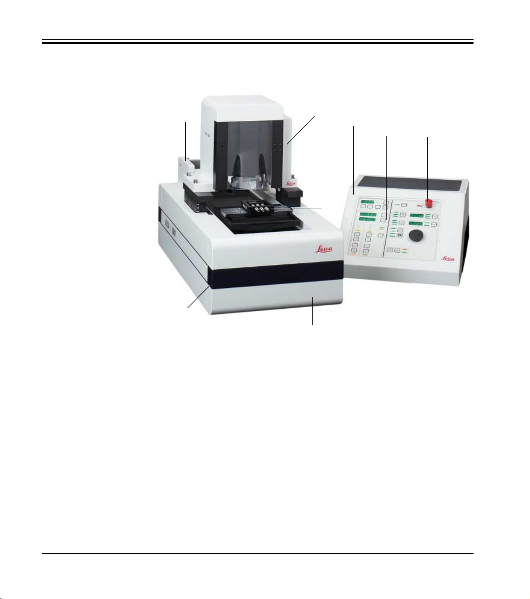
4.1 Overview - Leica SP2600 Ultramilling attachment / basic instrument Leica SM2500
- instrument parts / functions
1.4
1.2
1.5
Fig. 4.1 1
1.1
2
2.1 2.2
1.3
1. Leica SM2500 - basic instrument (sliding microtome)
1.1 Leica SP2600 - ultramilling attachment
1.2 Carrier for ultramilling attachment SP2600 (when not in use)
1.3 Specimen holder system (not part of standard delivery)
1.4 Carrying handle, black, rear (extendible - not visible in Fig. 4.1)
1.5 Carrying handle, black, front (extendible)
2. Leica SM2500 - control unit
2.1 Control panel
2.2 Emergency stop button
3. Foot switch (not shown in Fig. 4.1 - for details on the foot switch please
refer to p. 18, chapter 4.6 of this supplementary instruction manual and to
p. 18, chapter 4.5.2 and p. 24, chapter 5.4.1 of the Leica SM2500 manual).
14
Supplementary instruction manual V 1.2 07/2002
Page 15
4. Installation
4.2 Leica SP2600 standard delivery
Standard delivery includes:
1 Basic instrument Leica SP2600 (Ultramilling
attachment)
1 Calibrating device with dial gauge for miller
adjustment
3 Holders, each with two springs, for pre- and
finishing millers, one holder delivered attached
to the instrument.
1 Carrier for Leica SP2600 Ultramilling device
when not in use
1 Tool set:
1 Allen key, size 2.5, with handle
1 Allen key, size 4.0
1 Allen key, size 4.0 with handle
1 Allen key, size 5.0 with handle
1 Allen key, size, 8.0
1 Power cord type KN 2/5 7,5 V
1 Box level
1 Plexiglass block, 19 x 33 x 53 mm
1 Balance weight, installed in one of the miller
holders
1 Flat belt
1 Dust cover
1 Supplementary instruction manual for Leica
SP2600, to be used in conjunction with the
Leica SM2500 instruction manual
- German
- English
Millers and specimen holders are not
included in the instrument standard
delivery but have to be ordered separately, in accordance with each users
specific application(s).
Mounting instructions for all accessories and/or references to the corresponding chapters of the instruction
manual Leica SM2500 can be found in
chapter 5.6 of this instruction manual.
4.3 Site requirements
For site requirements, please refer to chapter 4.2
of the Leica SM2500 instruction manual.
4.4 Unpacking, transport, installation
Be sure to follow the unpacking instructions (attached to the outside of
the instrument shipping crate)!
Never remove or modify any of the
safety devices installed on the instrument and/or accessories!
The Leica SP2600 ultramilling attachment is supplied only in conjunction
with the Leica SM2500 microtome
(Leica SM2500 microtomes already installed at a customers site must be returned to the manufacturer for upgrading with a Leica SP2600 ultramilling
attachment).
For instructions on how to install / set up the Leica SM2500 please refer to chapter 4 of the Leica
SM2500 instruction manual.
Leica SP2600 Ultramilling attachment
15
Page 16
4. Installation
4.5 Installing the Leica SP2600 ultramilling attachment
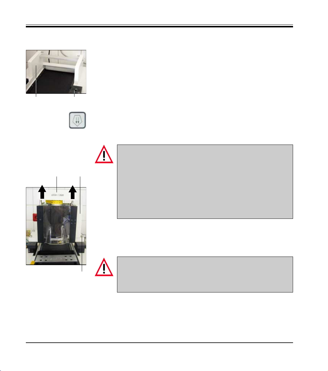
Place the carrier (1, Fig. 4.2) for the ultramilling attachment (3, Fig. 4.3) on
the rear part of the Leica SM2500 microtome fitting the two pins of the
carrier into the corresponding bores in the Leica SM2500 microtome.
1 2
Fig. 4.2
Lower the bearing blocks (2) of the microtome as far as they will go (use
button (51), chapter 5.4.13, p. 36 - Leica SM2500 manual).
Prior to placing the ultramilling attachment onto the microtome:
Make sure the bearing blocks of the microtome supporting the
milling attachment and the bearing surfaces of the milling attach-
34
ment are clean.
Two people are required to place the milling attachment on the
bearing blocks from above.
Do not slide the milling attachment onto the bearing blocks to prevent the bearing surfaces from getting scratched!
The bearing surfaces must not become damaged under any circumstances!
Fig. 4.3
16
Place ultramilling device (3) onto the microtome bearing blocks (two
people!).
Lift lid (4) of the milling attachment (serves as a handle - see Fig. 4.3).
Caution:
When releasing the lid of the milling attachment (can be lifted and
5
used as a handle) be careful not to get your fingers caught between the lid and the body of the milling attachment!
Fasten the ultramilling attachment to the microtome with four screws (5)
using a size 8 Allen key.
Connect the connecting cable of the milling attachment to the control
unit (see chapter 4.5.2, page 18 of the Leica SM2500 manual).
Supplementary instruction manual V 1.2 07/2002
Page 17

4.6 Connecting the vacuum cleaner
Milling dust is extracted by a vacuum cleaner, through a nozzle (1) located in
the milling area.
230 V / 50 Hz Vacuum cleaners with a power draw of maximum 4 A
can be connected directly to the SM2500 control unit and thus be
switched on/off via the vacuum cleaner button on the SM2500 con-
Fig. 4.4
1
Installing vacuum cleaners rated at 230 V/ 50 Hz / max. power draw 4 A
Insert the connection piece of the vacuum cleaner hose into nozzle (1) at
the rear of the ultramilling attachment.
Connect any one of the two adapter cables (both cables are identical)
supplied as part of the Leica SM2500 standard delivery into the vacuum
cleaner socket at the control unit (see chapter 4.5.2, p. 18 of the Leica
SM2500 manual).
Connect the vacuum cleaner power cord to the socket of the adapter
cable.
Switch on the on/off switch of the vacuum cleaner.
The vacuum cleaner can now be switched on/off via the vacuum cleaner
button on the control unit (button (35), chapter 5.4.11, p. 34 of the Leica
SM2500 manual).
trol unit.
4. Installation
Leica SP 2600 Ultrafräse
Caution!
Only the vacuum cleaner offered by Leica or other vacuum cleaner
brands rated at 230 V/ 50 Hz and a maximum power draw of 4 A can
be connected directly to the SM2500 control unit, and this only in
countries where the mains supply is 230 V / 50 Hz!
Otherwise, the vacuum cleaner must be connected directly to
mains and operated via the on/off switch of the vacuum cleaner.
Installing other vacuum cleaners:
Insert the connection piece of the vacuum cleaner hose into nozzle (1) at
the rear of the ultramilling attachment.
Connect the power cord of the vacuum cleaner to mains.
Operate the vacuum cleaner via the vacuum cleaner on/off switch.
17
Page 18

4. Installation
4.7 Installing additional accessories
Install further accessories as described in chapters 4.5.2 and 4.5.3, pages
18 and 19 of the Leica SM2500 instruction manual.
Connect the foot switch.
The foot switch must be connected - otherwise the instrument will
not be operational. --> For details on the foot switch, see chapter
4.5.2, p. 18 and chapter 5.4.1, p. 24 of the Leica SM2500 instruction
manual.
If working with vacuum stages, also a vacuum pump must be installed - --> see page 33, chapter 5.6.4 of this supplementary instruction manual.
18
Supplementary instruction manual V 1.2 07/2002
Page 19

5.1 Overview of chapter 5 Operation
Prior to working with the Leica SP2600 ultramilling attachment, be
sure to read the following instruction manuals:
The entire Leica SM2500 instruction manual except chapters
5.5.6 through 5.7.
This supplementary instruction manual Leica SP2600.
Chapter 5 of this supplementary instruction manual Leica SP2600 includes
the following subchapters:
5.1 Overview - chapter 5.
5.2 Adjusting the pre-millers in the calibrating device
5.3 Adjusting the finishing millers in the calibrating device
5.4 Specimen holder systems - how to combine individual components
5.5 Clamping specimens
5.5.1 Installing the base plates in the basic instrument
5.5.2 Clamping the specimen holders in the base plate with dovetail guide
5.5.3 Clamping the vacuum stages on/in the base plates
5.5.4 Connecting the vacuum pump/placing specimens onto the vacuum
stages
5.6 Preparatory steps prior to the milling procedure
5.7 Pre-milling
5.7.1 Perspective view of the pre-milling procedure
5.8 Finishing milling
5.8.1 Perspective view of the finishing milling procedure
5.9 Switching the instrument off (switching off the control unit).
5. Operation
Initial operation:
The first time you operate the instrument, we recommend you work through
the above subchapters, in numerical order as listed.
Pay particular attention to the safety instructions..
Leica SP 2600 Ultramilling attachment
19
Page 20

5. Operation
5.2 Adjusting the pre-millers in the calibrating device
Preparatory steps
Connect mains power supply (20) to miller cali-
bration device (18).
Connect mains power supply (20) to mains: the
light bulb is switched on.
20
18
16
1
Place magnifier (16) onto calibration device.
Loosen regulating screws (6), (7) and (11) in
miller holder (2) until they are flush with the
inner surfaces of the miller holder.
If the screws protrude from the inner surfaces
of the miller holder (2), spring (1) and miller (3)
cannot be inserted into the correct position.
Twisted or deformed springs for the
miller holders must be exchanged!
Fig. 5.1
4
Fig. 5.2
20
Inserting the miller into the miller holder
Insert spring (1) straight from above into miller
holder (2) - the two upper edges of the spring
must be flush with the upper surface of the
6
11
miller holder.
Carefully insert miller (3) from the front - the
letter V must be visible.
6
When the miller is inserted into the
holder the letter V must be visible. That way, the milling edge is pointing
into the right direction.
Insert the miller (3) completely - it must fit
3
7
5
2
against the rear and lower inner surface of the
miller holder (2) and be flush with spring (1).
Insert screw (4) and washer (5) and tighten
slightly to fasten miller (3) .
Supplementary instruction manual V 1.2 07/2002
Page 21

5. Operation
Z
Fig. 5.3
Y
Adjusting the miller
The miller (3) is adjusted in the holder (2) along
6
three different axis (x, y and z - see Fig. 5.3, left).
Adjustment along the x-axis is done outside the
6
calibration device (18, Fig. 5.1).
X
For adjustment along the z- and y-axis, the miller
holder (2) with miller (3) has to be fastened in the
calibration device.
Adjustment along the x-axis
Adjust miller (3) as shown in Fig. (5.4a / 5.4b).
Along the entire length of both sides of the
miller, there must be a uniform distance between miller (3) and miller holder (2) / spring
(1) (see Fig. 5.4b).
The miller is adjusted along the x-axis via the
two regulating screws (6) (Allen key, size 2.5).
Tighten (clockwise) and/or loosen (counter-
2
3
clockwise) screws (6, Fig. 5.3) alternately un-
til the miller is adjusted to a parallel position
as shown in Fig. 5.4b.
132
Fig. 5.4a: WRONG Fig. 5.4b: CORRECT
Leica SP2600 Ultramilling attachment
Do not tighten screws (6) too much. If
screws (6) are too tight, screw (7, Fig.
5.2) (for adjustment along the y-axis)
can no longer be moved.
21
Page 22

5. Operation
12
(12)
18
Adjustment along the z-axis
1. Pull lever (12) at the left of calibration device
(18) forward as far as it will go, thus moving
contact plate (17) backwards to its rear limit
position. This prevents the contact plate from
hitting the milling edge during the adjustment
procedure.
2. Once miller (3) has been correctly adjusted
along the x-axis, place miller holder (2) with
16
10
17
miller (3) next to block (8) into the calibration
device.
3. Fit the clamping device (9) (with the semicir-
cular recess pointing in your direction) against
the miller holder (2) and fasten with two
knurled screws (10) (turn screws clockwise).
9
2 38
Fig. 5.5
4. Rotate magnifier (16) forward to a position
above the miller.
5. With lever (12), bring contact plate (17) close
to the miller (move lever backwards) until just
a very small gap remains (see Fig. 5.6).
Caution:
The gauge contact plate must never hit
the milling edge.
This could damage the surface of the
contact plate, leading to incorrect
measuring results.
Be very careful when bringing the contact plate close to the milling edge.
Always use the magnifier.
Fig. 5.6
22
17
Supplementary instruction manual V 1.2 07/2002
Page 23

5. Operation
6. Insert the size-5 Allen key into regulating
11
3
screw (4) insert size-2.5 Allen key into regulating screw (11) (Fig. 5.7).
The arrows in Fig. 5.7 indicate clockwise sense of rotation.
Fig. 5.7 4
Fig. 5.8 a - CORRECT
Fig. 5.8 b - WRONG
7
90°
7. Tighten/loosen screws (11) and (4) alternately
to adjust miller (3) along the z-axis. The miller
edge is adjusted correctly when the outer
edge of the miller is at right angles to the front
surface of the contact plate (see Fig. 5.8a).
The miller MUST NOT be positioned as shown
in Fig. 5.8b and 5.8c!
Tightening either regulating screw (4,
11) (= clockwise rotation in the sense
of the arrow) brings the corresponding
side of the miller closer to the contact
plate.
8. If one of the two screws (4, 11) has been tightened as far as it will go, slightly release the
opposite screw. This slackens the screw that
had been completely tightened .
Do not tighten screws (4, 11) too much.
If screws (4, 11) are too tight, screw (7,
Fig. 5.2) (for adjustment along the yaxis) can no longer be moved.
Fig. 5.8 c - WRONG
Leica SP2600 Ultramilling attachment
Caution:
Be very careful when bringing the
contact plate close to the milling
edge.
Always use the magnifier.
Make sure the milling edge does not
hit the contact plate!
23
Page 24

5. Operation
12
Fig. 5.9 a
Adjustment along the y-axis
1. Select reference value 1.
14
13
17
3
The reference value will be needed
later on to adjust the finishing miller to
the same milling level as the premiller.
Any reference value can be selected.
Experience, however, shows that 1 is
the best value for new millers (i.e. millers not yet resharpened).
2. To select the reference value, move lever (12),
setting the dial of the inner (smaller) scale (13)
to a position just below 1 and the dial of the
outer scale (14) to approximately 70 (approx.
7
10 oclock) (Fig. 5.9a).
3. Rotate regulating screw (7) clockwise, bringing the milling edge (3) close to the contact
plate (17).
4. Slowly continue to turn screw (7) clockwise
until the dial of scale (14) starts to move (i.e.
14
until the milling edge touches the contact
plate).
5. Keep rotating screw (7) very carefully and
13
slowly until the dial of scale (14) is in the upper 0 position and the dial of scale (13) is located exactly at 1 (Fig. 5.9b).
Fig. 5.9 b
24
Caution:
Be very careful when bringing the contact plate close to the milling edge.
Always use the magnifier.
Make sure the milling edge does not
hit the contact plate!
7
Supplementary instruction manual V 1.2 07/2002
Page 25

5. Operation
5.3 Adjusting the finishing millers in the
calibrating device
Carry out preparatory steps as per chapter 5.2,
page 20 (Adjusting the pre-millers in the calibrating device).
Twisted or deformed springs for the
miller holders must be exchanged!
Insert spring and finishing miller as described
in chapter 5.2, page 20 (Inserting the miller into
the miller holder).
When the finishing miller is inserted
into the holder, the letter F must be
visible. - That way, the milling edge is
pointing into the right direction.
Fig. 5.10
Leica SP2600 Ultramilling attachment
25
Page 26

5. Operation
12
Adjusting the finishing miller
Just like the pre-miller, the finishing miller is adjusted in the miller holder along three different
axis (see page 21).
Adjustment along the x-axis
As described for the pre-miller - see page 21.
Adjustment along the z-axis
Carry out steps 1 - 4 as described on page 22
(Fig. 5.5) for the pre-miller.
Next:
5. With lever (12), bring contact plate (17) close
to the miller (turn lever backwards) so that only
a small gap remains (see Fig. 5.11).
Caution:
The gauge contact plate must never hit
the milling edge.
This could damage the surface of the
contact plate, leading to incorrect
measuring results.
Be very careful when bringing the contact plate close to the milling edge.
Always use the magnifier.
Fig. 5.11
26
17
Supplementary instruction manual V 1.2 07/2002
Page 27

5. Operation
6 Insert size-5 Allen key into regulating screw
11
3
(4) insert size-2.5 Allen key into regulating
screw (11) (Fig. 5.12) .
The arrows in Fig. 5.12 indicate clockwise sense of rotation.
Fig. 5.12 4
a
Fig. 5.13 a - CORRECT: angle a = angle b
Fig. 5.13 b - WRONG
7
b
7 Tighten/loosen screws (11) and (4) alternately
to adjust miller (3) along the z-axis. The miller
is adjusted correctly when angle a equals
angle b, i.e. when the distance between each
end of the milling edge and the contact plate
is the same: in Fig. 5.13a the finishing miller
correctly adjusted.
The miller MUST NOT be positioned as shown
in Fig. 5.13b and 5.13c!
Tightening either regulating screw (4,
11) (= clockwise rotation in the sense
of the arrow) moves the corresponding
side of the miller towards the contact
plate.
8. If one of the two screws has been tightened
as far as it will go, slightly release the opposite screw . This slackens the screw that had
been completely tightened.
Do not tighten screws (4, 11) too much.
If screws (4, 11) are too tight, screw (7)
(for adjustment along the y-axis) can
no longer be moved.
Fig. 5.13 c - WRONG
Leica SP2600 Ultramilling attachment
Caution:
Be very careful when bringing the
contact plate close to the milling edge.
Always use the magnifier.
Make sure the milling edge does not
hit the contact plate!
27
Page 28

5. Operation
12
Fig. 5.14 a
Adjustment along the y-axis
1 Select the same reference value as was set
for the pre-miller.
14
13
17
3
7
2 To select the reference value, move lever (12),
setting the dial of the inner (smaller) scale (13)
Pre-miller and finishing miller used for
milling a specific sample must be adjusted using the same reference value.
This ensures that both milling edges
hit the sample at exactly the same
height.
Minor differences in height can still be
adjusted via the height adjustment button on the control unit, once the miller
holder has been attached to the milling
spindle (see chapter 5.4.13, p. 36 the
Leica SM2500 manual).
to a position just below 1 and the dial of the
outer scale (14) to approximately 70 (approx.
10 oclock) (Fig. 5.14a).
3 Rotate regulating screw (7) clockwise, bring-
ing the milling edge (3) close to the contact
plate (17).
14
4 Slowly continue to turn screw (7) clockwise
until the dial of scale (14) starts to move (i.e.
13
until the milling edge touches the contact
plate).
5 Keep rotating screw (7) very carefully and
slowly until the dial of scale (14) is in the upper 0 position and the dial of scale (13) is located exactly at 1 (Fig. 5.14b).
Fig. 5.14 b
28
Caution:
Be very careful when bringing the contact plate close to the milling edge.
Always use the magnifier.
Make sure the milling edge does not
7
Supplementary instruction manual V 1.2 07/2002
hit the contact plate!
Page 29

5.4 Specimen holder systems - how to combine individual components
5. Operation
Base plate
with vise
0383 09267
Base plate with
dovetail guide
0383 09422
Vacuum stage
adapter for base
plate with vise
0383 60407
Vacuum stage
adapter for base
plate with
dovetail guide
0383 20351
Specimen clamp
44 x 58 mm, for
base plate with
dovetail guide
0383 09415
Round specimen
holder,
for base plate
with dovetail
guide
0383 08992
Vacuum stage
55 x 100 mm
0364 09011
Vacuum stage
for lids
30 - 50 mm
0364 09001
Vacuum stage
76 x 25 mm,
for perforated
specimen holders
0364 18199
Vacuum stage
with variable
surface:
76 x 25, 76 x 65
and 100 x 65 mm,
for perforated
specimen holders
0364 18197
SPECIMEN
SPECIMEN
SPECIMEN
Lid, 30 mm
0364 09005
Lid, 40 mm
0364 09007
Lid, 50 mm
0364 09009
Specimen holder,
perforated,
in 9 different sizes:
5 x 5 perforations
0364 26808
5 x 10 perforations
0364 26809
10 x 10 perforations
0364 26810
10 x 15 perforations
0364 26811
15 x 15 perforations
0364 26812
20 x 10 perforations
0364 26813
20 x 15 perforations
0364 26814
25 x 15 perforations
0364 26815
30 x 15 perforations
0364 26816
SPECIMEN
SPECIMEN
Configurations:
1. Base plate with dovetail guide (0383 09422) and holder for round specimens (0383 08992)
= order no. 0383 08993
2. Base plate with dovetail guide (0383 09422) and specimen clamp 44 x 58 mm (0383 09415) with eccentric ring (0383 09425)
= order no. 0383 20212
3. Vacuum stage 76 x 25 mm with vacuum stage adapter (0383 60407) for base plate with vise (0383 09267)
= order no. 0364 18200
Leica SP 2600 Ultramilling attachment
29
Page 30

5. Operation
5.5 Clamping specimen
For a detailed overview of the clamping systems available, please
refer to chapter, 5.4, page 29.
5.5.1 Installing the base plates in the basic instrument
For detailed instructions on how to install the base plates in the
basic instrument, please refer to chapters 5.5/5.5.1, pages 38/39 of
the Leica SM2500 instruction manual.
When working with the Leica SP2600 ultramilling attachment, always insert the eccentric ring prior to installing the base plates.
The eccentric ring blocks the specimen orientation mechanism
thus providing enhanced stability during milling.
For details on how to insert the eccentric ring, please refer to
chapter 5.5/5.5.1, page 39 of the Leica SM2500 instruction manual.
5.5.2 Clamping the specimen holders in the base plate with dove tail guide
30
For detailed instructions on how to clamp the specimen clamp 44 x
58 mm and/or the round specimen holder in the base plate with
dovetail guide as well as on how to clamp specimens in these
specimen holders, please refer to chapter 5.5.4 Mounting specimen holders onto the base plate with dovetail guide, pages 42 - 44
of the Leica SM2500 instruction manual.
Supplementary instruction manual V 1.2 07/2002
Page 31

Fig. 5.15
5. Operation
5.5.3 Clamping the vacuum stages on/in the base plates
Clamping the vacuum stages in the base plate
with vise (Fig. 5.15)
Fasten the vacuum stage on the vacuum stage
adapter for the base plate with vise (with 4
Allen screws (1) / Allen key size 4).
The 4 size-four Allen screws are part of the
Vacuum stage adapter standard delivery, the
size-four Allen key comes as part of the Leica
SP2600 standard delivery.
Clamp the vacuum stage in the base plate with
vise.
For detailed instructions on how to do this,
please refer to chapter 5.5.2, page 41 Clamping specimen stages of the Leica SM2500 instruction manual: the vacuum stage is
clamped the same way as the specimen
1
stages described there.
Fig. 5.16
Leica SP2600 Ultramilling attachment
Clamping the vacuum stages in the base plate
with dovetail guide (Fig. 5.16)
Fasten the vacuum stage on the vacuum stage
adapter for the base plate with dovetail guide
(with 4 Allen screws (1) / Allen key size 3).
The 4 size-three Allen screws are part of the
Vacuum stage adapter standard delivery, the
size-three Allen key comes as part of the Leica
SM2500 standard delivery.
Clamp the vacuum stage in the base plate with
dovetail guide.
For detailed instructions on how to do this,
please refer to chapter 5.5.4, page 44 Clamping the round specimen holder of the Leica
SM2500 instruction manual: the vacuum stage
is clamped the same way as the round specimen holder.
31
Page 32

5. Operation
5.5.4 Connecting the vacuum pump / placing specimens onto the vacuum stages
IMPORTANT:
Prior to first use, every vacuum table
surface must be milled once, just like
a specimen surface. This ensures that
the surface of the specimens milled on
the table later on will be perfectly
even.
To mill a table surface, carry out one
entire pre- and finishing milling cycle
as per chapters 5.6 - 5.8, pages 34 - 43
of this manual.
Fig. 5.17
Fig. 5.18
12
Connecting the vacuum pump
Place vacuum pump (make sure the voltage
rating of the vacuum pump is appropriate for
the mains supply in your laboratory!) on the
floor underneath the microtome bench.
Connect vacuum pump to mains.
Slide connecting hose (1) (part of standard
delivery of Leica vacuum pumps) onto the
nozzle on vacuum pump (2).
Connect the other end of connecting hose (1)
to the nozzle (3) of the vacuum stage.
Place the specimen onto the vacuum stage.
There are different types of vacuum
stages for different specimen sizes see next page.
32
Supplementary instruction manual V 1.2 07/2002
Page 33

5. Operation
Placing specimens onto vacuum stage for 30 -
50-mm lids
Fasten a lid suited to the size of the specimen
to be milled onto the vacuum stage (slotted
screws are part of standard delivery of
vacuum stage lids - use slotted screwdriver).
Place the specimen (1) onto the sintered sur-
face (2) of the lid.
Switch on the vacuum pump.
Fig. 5.19 12
Fig. 5.20 3
Fig. 5.21 4
Placing specimens onto vacuum stages for per-
forated specimen holders
Fasten a perforated specimen holder (3) suited
to the size of the specimen on the vacuum
stage 76 x 25 mm (4) or onto the vacuum stage
with variable surface (not shown here).
Place specimen on the perforated area of the
vacuum stage
Switch on the vacuum pump.
The following is recommended for all
vacuum stages, no matter of which
type and size:
If the specimen is smaller than the sintered or perforated stage surface, the
entire stage surface not covered by the
specimen should be covered with
autoadhesive plastic film.
Placing specimens onto vacuum stage 55 x 100
mm
Place the specimen directly on the sintered
surface area of the vacuum stage.
(Vacuum stage 55 x 100 mm not shown here).
Leica SP2600 Ultramilling attachment
33
Page 34

5. Operation
5.6 Preparatory steps prior to the milling procedure
For a detailed description of all control elements located on the
control unit, please refer to chapters 5.3 (Overview - control
panel) and 5.4 (Description of each individual control element) of
the Leica SM2500 instruction manual.
Select manual mode of operation MAN (button (5) - chapter 5.4.3, page
26, Leica SM2500 instruction manual).
In MAN mode, carry out the following preparatory steps:
Move the milling spindle to the upper limit position (button (48), chapter
5.4.13, p. 36, Leica SM2500 manual) and open the plexiglass cover.
Attached the miller holder (1) (containing the adjusted pre-miller) to the
milling spindle (use Allen screws size 5 (2) / Allen key size 5 - part of
SP2600 standard delivery).
Always slide plexiglass cover to upper position prior to attaching
the miller holders to the milling spindle!
34
1
2
Fig. 5.22
Supplementary instruction manual V 1.2 07/2002
Page 35

5. Operation
Insert the specimen (see chapters 5.5.2 and 5.5.4, pages 30 and 33 of this
manual) or - if you need to mill a vacuum table prior to first use - see
chapter 5.5.3, page 31 of this manual).
Wear protective gloves when working with potentially infectious
specimen material!
or
or
Move the specimen sledge underneath the miller (buttons (56) or (57),
chapter 5.4.14, page 37, Leica SM2500 instruction manual).
Set the milling window (button (61) and others - see chapter 5.4.14, page
37, Leica SM2500 instruction manual).
Press button (51) (chapter 5.4.13, page 36, Leica SM2500 manual) to bring
the cutting edge of the miller close to the specimen surface (coarse adjustment - small gap must still remain).
Always slide the plexiglass cover to the upper position prior to the
distance check milling edge / specimen surface! - Risk of injury!
Next, use buttons (50) and/or (49) (see chapter 5.4.13, page 36, Leica
SM2500 instruction manual) for fine adjustment of the distance between
milling edge and specimen surface.
Check the remaining distance in three different zones of the specimen
surface (beginning/center/end) moving the specimen sledge via buttons
(56) - (59), see chapter 5.4.14, page 37, Leica SM2500 manual) - the cutting edge of the miller should just about touch the specimen surface.
Caution:
Always check the distance between miller cutting edge and
specimen surface thoroughly prior to milling!
Under no circumstances may the miller cutting edge be positioned
more than a few microns (= selected milling thickness) below the
specimen surface when starting the milling procedure.
Leica SP 2600 Ultramilling attachment
If the surface height of the specimen is uneven, the cutting edge
should just about touch the highest point of the specimen. - Then
mill the specimen until the surface is completely level.
35
Page 36

5. Operation
5.7 Pre-milling
or
+
+
Select automatic mode of operation AUTO (button (5) - chapter 5.4.3, page
26 Leica SM 2500 instruction manual).
In AUTO mode, set the milling parameters for the pre-milling procedure:
Select STOP or PHOTO position (buttons (23) or (26) chapter 5.4.8, page
31 - Leica SM2500 instruction manual).
Select milling thickness (button (10) / rotary selector switch (9) - see
chapters 5.4.4 and 5.4.5, pages 27/28 - Leica SM2500 instruction manual).
(--> see following page for recommended settings).
Activate retraction (button (10) / rotary selector switch (9) - see chapters
5.4.4 and 5.4.5, pages 27/28 - Leica SM2500 instruction manual).
Select milling and return stroke speed.
(button (19) / rotary selector switch (9) - see chapter 5.4.4, page 27 and
chapter 5.4.7, page 30 - Leica SM2500 instruction manual).
(see next page for recommended settings).
36
or
Close plexiglass protective cover.
Start miller rotation (button (37) - chapter 5.4.11, page 34 - Leica SM2500
instruction manual).
Select rotational speed of miller (buttons (39), (40) - chapter 5.4.11, page
34 - Leica SM2500 instruction manual).
Select desired milling mode (button (15) - chapter 5.4.6. page 29 - Leica
SM2500 instruction manual).
Individual parameter settings depend on specimen material and
size. Please refer to the following page for a list of recommended
settings.
Supplementary instruction manual V 1.2 07/2002
Page 37

5. Operation
Recommended milling thickness settings for pre-milling
10 µm - keep milling until surface is completely level.
5 µm - three entire sledge strokes (milling and return stroke).
3 µm - three entire sledge strokes (milling and return stroke).
Do not exceed a milling thickness setting of 5 µm with the following materials: brittle, very ductile materials such as titanium or fiberglass and compound samples containing such materials (such
as printed circuit boards).
Recommended sledge speed settings for pre-milling
Milling stroke: 1.5 mm/s
Return stroke: any speed
Recommended rotational speed of miller for pre-milling
2,000- 3,000 rpm (depending on specimen type)
Recommended mode of operation for pre-milling
Select continuous mode of operation.
Starting the milling procedure
Switch on the vacuum cleaner (via button (35) on the control unit - see
chapter 5.4.11, page 34 of Leica SM2500 instruction manual) or via the
on/off switch of the vacuum cleaner itself.
Start sledge stroke (buttons (29), (30) - chapter 5.4.10, p. 33 - Leica
+
SM2500 instruction manual).
Carry out the milling steps as per above recommendation.
--> See next page for a perspective view of the pre-milling procedure.
Leica SP 2600 Ultramilling attachment
During milling:
switch on the vacuum cleaner,
wear appropriate safety goggles,
wear appropriate mask (type of mask depends on the material
being milled / size of the chips that form during milling).
Goggles and mask prevent milling chips and microdust from entering your eyes and from being inhaled.
37
Page 38

5. Operation
5.7.1 Perspective view of the pre-milling procedure
1
2
38
Fig. 5.23
Pre-milling procedure
The milling spindle carrying the pre-miller rotates clockwise (circular arrow
(1)) while the specimen sledge passes underneath the miller in the direction
of arrow (2).
The pre-miller leaves a serrated surface texture which is then in a second
milling procedure milled to a mirrorlike, even surface by the finishing miller
(see Fig 5.24 p. 42).
Supplementary instruction manual V 1.2 07/2002
Page 39

5. Operation
Ending the pre-milling procedure
or
Press RUN STOP or RUN ENABLE to stop the sledge (buttons (29), (30) -
Chapter 5.4.10, page 33 - Leica SM2500 manual) - or, when working in
PROG mode of operation, wait for the programmed number of strokes to
be finished (see chapter 5.4.3, page 26, Leica SM2500 manual).
If the specimen sledge has not stopped in the front limit position, activate
manual mode of operation MAN (button (5) - chapter 5.4.3, page 26,
Leica SM2500 manual) and move the specimen to the front limit position
(via buttons (58) or (59) - chapter 5.4.14, page 37- SM2500 manual) .
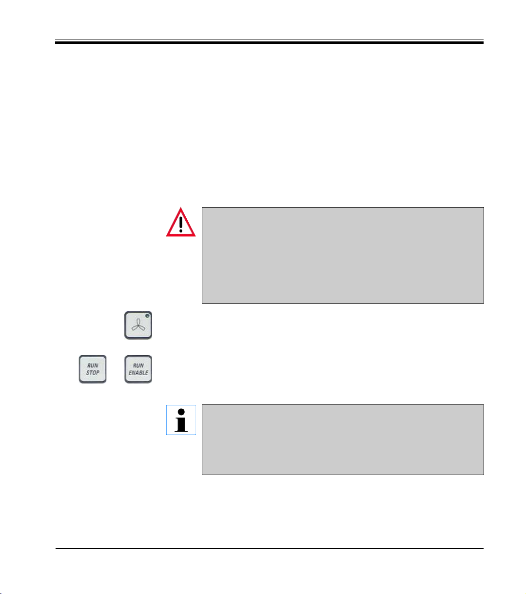
Stop miller rotation (button (37) - chapter 5.4.11, page 34 - Leica SM2500).
After switching off the milling spindle (button (37) - chapter. 5.4.11,
p. 34 - instruction manual Leica SM2500) the miller continues to
rotate for a little while!
Risk of injury!
Slide plexiglass protective cover to upper position.
Never touch the milling spindle while it is rotating and/or while
the plexiglass cover is shut, no matter whether the spindle is rotating or not.
Remove the miller holder containing the pre-miller.
Leica SP 2600 Ultramilling attachment
39
Page 40

5. Operation
5.8 Finishing milling
Attach the miller holder containing the finishing miller to the milling
spindle (Allen screws / Allen key size 5) - see Fig. 5.21, page 34).
Always slide the plexiglass cover to the upper limit position prior
to attaching the miller holders to the milling spindle!
Bring the cutting edge of the miller close to the specimen surface and
thoroughly check the distance between miller cutting edge and specimen surface as described for the pre-miller on page 35.
If necessary, adjust the milling window (button (61) and others - see
chapter 5.4.14, page 37 of Leica SM2500 instruction manual).
Setting the milling parameters for the finishing milling procedure
Once again activate automatic mode of operation AUTO and set the
milling parameters using the same control unit buttons as described for
the pre-miller on page 36.
Individual parameter settings depend on specimen material and
size. Please refer to the recommendations below and on the following page.
40
Recommended milling thickness settings for finishing milling
5 µm - keep milling until surface is completely level.
3 µm - three entire sledge strokes (milling and return stroke).
2 µm - three entire sledge strokes (milling and return stroke).
1 µm - three entire sledge strokes (milling and return stroke).
Do not exceed a milling thickness setting of 5 µm with the following materials: brittle, very ductile materials such as titanium or fiberglass and compound samples containing such materials (such
as printed circuit boards).
Supplementary instruction manual V 1.2 07/2002
Page 41
5. Operation
Recommended sledge speed settings for finishing milling
Milling stroke: 0.5 mm/s to 1.0 mm/s
Return stroke: any speed
Recommended rotational speed of miller for finishing milling
< 2.000 rpm
Recommended mode of operation for finishing milling
Select continuous mode of operation.
Starting the milling procedure
During milling:
switch on the vacuum cleaner,
wear appropriate safety goggles,
wear appropriate mask (type of mask depends on the material
being milled / size of the chips that form during milling).
Goggles and mask prevent milling chips and microdust from entering your eyes and from being inhaled.
Switch on the vacuum cleaner (via button (35) on the control unit - see
chapter 5.4.11, page 34 of Leica SM2500 instruction manual) or via the
on/off switch of the vacuum cleaner itself.
Start sledge stroke (buttons (29), (30) - chapter 5.4.10, p. 33 - Leica
+
SM2500 instruction manual).
Carry out the milling steps as per above recommendation.
--> See following page for a perspective view of the finishing milling procedure.
Leica SP 2600 Ultramilling attachment
Important note:
If you need to mill several specimens with identical results (e.g.
for examining a specimen layer located at a certain level), completely identical parameters have to be selected for each specimen (for pre-milling as well as for the finishing milling procedure).
41
Page 42

5. Operation
5.8.1 Perspective view of the finishing milling procedure
1
42
2
Fig. 5.24
Finishing milling procedure
The milling spindle carrying the finishing miller rotates clockwise (circular
arrow (1)) while the specimen sledge passes underneath the miller in the direction of arrow (2).
The serrated surface structure created by the pre-miller (see Fig 5.23 p. 38)
is converted by the finishing miller into a mirrorlike, completely even surface.
Supplementary instruction manual V 1.2 07/2002
Page 43

Ending the finishing milling procedure
5. Operation
or
Press RUN STOP or RUN ENABLE to stop the sledge (buttons (29), (30) -
chapter 5.4.10, page 33 - Leica SM2500 manual) - or, when working in
PROG mode of operation, wait for the programmed number of strokes to
be finished (see chapter 5.4.3, page 26, Leica SM2500 manual)
If the specimen sledge has not stopped in the front limit position, activate
manual mode of operation MAN (button (5) - chapter 5.4.3, page 26, Leica
SM2500 manual) and move the specimen to the front limit position (via
buttons (58) or (59) - chapter 5.4.14, page 37- SM2500 manual) .
Stop miller rotation (button (37) - chapter 5.4.11, page 34 - Leica SM2500).
After switching off the milling spindle (button (37) - chapter. 5.4.11,
p. 34 - instruction manual Leica SM2500) the miller continues to
rotate for a little while!
Risk of injury!
Remove the specimen for subsequent microscopic examination.
Slide plexiglass protective cover to upper position.
Never touch the milling spindle while it is rotating and/or while
the plexiglass cover is shut, no matter whether the spindle is rotating or not.
Remove the finishing miller.
5.9 Switching the instrument off (switching off the control unit)
Once all milling procedures have been completed or at the end of your
workday, switch off the mains switch at the rear of the control unit.
When switching off the mains switch on the control unit (see
chapter 5.2, p. 21 - Instruction manual Leica SM2500) the milling
spindle will rotate briefly.
Therefore, never switch off the control unit, while one of your
hands is in the rotation zone of the miller.
- Risk of injury!.
Leica SP 2600 Ultramilling attachment
43
Page 44

6. Troubleshooting
6. Troubleshooting
For all instructions on error detection and trouble shooting, please refer to
chapter 6, page 64 of the Leica SM2500 instruction manual .
44
Supplementary instruction manual V 1.2 07/2002
Page 45

7.1 Cleaning and disinfection
Cleaning
Clean the basic instrument Leica SM2500 as per the instructions in chap-
ter 7.1, pages 65 - 67 of the Leica SM2500 instruction manual.
Clean the Leica SP2600 with a soft, slightly moistened cloth using one of
the detergents listed above.
Clean diamond millers with a soft cloth moistened with alcohol.
7. Cleaning, disinfection and maintenance
Only authorized service technicians may access the internal components of the instrument for service and repair!
Cleaning detergents appropriate for the ultramilling attachment varnished surfaces:
mild laboratory detergents (slightly moistened cloth)!
non-varnished metal parts:
mild laboratory detergents,
xylene substitutes (slightly moistened cloth)
alcohol (slightly moistened cloth).
No liquids may enter the interior of the instrument during cleaning!
Disinfection
Remove potentially infectious milling waste / remaining samples and dis-
pose of as per the regulations applicable.
Disinfect instrument and accessories as per the instructions of the disin-
fectant manufacturer.
Leica SP 2600 Ultramilling attachment
For disinfection of the instrument and accessories use Leica Cryofect or other commercial disinfectants. - Use all disinfectants according to the manufacturers instructions!
No liquids may enter the interior of the instrument during disinfection!
When disinfecting, wear appropriate goggles and mask as well as
protective gloves!
Dispose of potentially infectious specimen material as per the
laboratory regulations applicable in the country of operation!
45
Page 46

7. Cleaning, disinfection and maintenance
7.2 Maintenance
Only authorized service technicians may access the internal components of the instrument for service and repair!
No liquids may enter the interior of the instrument during maintenance!
Carry out the maintenance steps to be done by the user as per the in-
structions in chapter 7.2, pages 67 - 70 of the Leica SM2500 instruction
manual.
In addition to the maintenance steps listed in the Leica SM2500 manual,
the following maintenance work is required for the Leica SP2600:
chapter 7.2.1 - Resharpening the millers.
chapter 7.2.2 - Replacing the light bulb in the calibration device.
7.2.1 Resharpening the millers
The millers need to be resharpened as soon as the milled specimen sur-
faces no longer have a smooth, mirrorlike appearance and/or when milling residues / residues of a grimy appearance start to accumulate on the
specimen surface.
46
Supplementary instruction manual V 1.2 07/2002
Page 47

7. Cleaning, disinfection and maintenance
7.2.2 Replacing the light bulb in the calibration device
Remove base cover (2) of calibration device (1) (unscrew 4 slotted
screws (3)).
Loosen light bulb holder (5) (metal bridge with lamp socket) (unscrew 2
slotted screws (4)).
Take replacement light bulb (8) out of sponge rubber cube (7).
Remove broken light bulb (6) from lamp socket and replace with new
light bulb (8).
Place another replacement bulb (8) into the sponge rubber cube (7).
Put light bulb holder (5) back in place.
Place ring with cable (9) onto bore (10) in the light bulb holder.
Fasten light bulb holder with two screws (4).
Put sponge rubber cube (7) with new replacement light bulb (8) back into
the calibration device.
Put base cover (2) back in place and fasten with 4 screws (3).
7
1
Fig. 7.1
Leica SP 2600 Ultramilling attachment
8
5
6
10
9
2
4
3
47
Page 48

8. Overview - accessories
8.1 Miller holders and millers
Miller holder
Holder for pre- and finishing miller
Pre-miller
Pre-miller D - with diamond edge, cutting angle -1°, clearance angle +3°
Finishing miller
Finishing miller D - with diamond edge, cutting angle +3°, clearance
angle +4°, for milling plastics
Finishing miller D - with diamond edge, cutting angle -8°, clearance angle
+1.5°, for milling precious and nonferrous heavy metals
Finishing miller D - with diamond edge, cutting angle -1°, clearance angle
+1.5°, for milling light metals
Finishing miller D - with diamond edge, cutting angle -5°, clearance angle
+1.5°, for milling light metals
Counterbalance insert - for Leica SP2600 - to be used instead of a pre- or
finishing miller
8.2 Base plates for specimen holders and vacuum stage adapters
Base plate with vise
Base plate with dovetail guide
8.3 Specimen holders
Specimen clamp 44 x 58 mm,
for base plate with dovetail guide
Round specimen holder, for base plate with dovetail guide
8.4 Vacuum stage adapters
Vacuum stage adapter for base plate with vise
Vacuum stage adapter for base plate with dovetail guide
48
Supplementary instruction manual V 1.2 07/2002
Page 49

8. Overview - accessories
8.5 Vacuum stages and matching lids / perforated specimen holders
Vacuum stage for Leica SP2600 - basic body for lids 30 - 50 mm
Lid, 30 mm, for Leica SP2600 vacuum stage
Lid, 40 mm, for Leica SP2600 vacuum stage
Lid, 50 mm, for Leica SP2600 vacuum stage
Vacuum stage for Leica SP2600 - 55 x 100 mm
Vacuum stage, 76 x 25 mm
Available either configured (with vacuum stage adapter for base plate
with vise) or without vacuum stage adapter.
To be used with several different perforated specimen holders:
specimen holder, 5 x 5 perforations
specimen holder, 5 x 10 perforations
specimen holder, 10 x 10 perforations
specimen holder, 10 x 15 perforations
specimen holder, 15 x 15 perforations
specimen holder, 20 x 10 perforations
specimen holder, 20 x 15 perforations
specimen holder, 25 x 15 perforations
specimen holder, 30 x 15 perforations
Vacuum stage, with variable surface: 76 x 25 mm, 76 x 56 mm
and 100 x 65 mm.
To be used with the same perforated specimen holders as vacuum stage
76 x 25 mm.
8.6 Vacuum pumps
Vacuum pump, 230 V, 50 Hz
Vacuum pump, 120 V, 60 Hz
Leica SP 2600 Ultramilling attachment
49
Page 50

8 Overview - accessories
8.7 Additional accessories
Vacuum cleaner and vacuum cleaner accessories
Vacuum cleaner Fakir S20, with connection hose
230 V / 50 Hz only
Set of vacuum cleaner bags for Fakir S 20
Illumination
Halogen spotlight illumination
230 V/50 Hz only
50
Supplementary instruction manual V 1.2 07/2002
Page 51

9. Warranty and service
For all information on warranty and service, please refer to chapter 9, pages
74 - 76 of the Leica SM2500 instruction manual.
9. Warranty and service
Leica SP 2600 Ultramilling attachment
51
 Loading...