

Page 1

LEICA M7
Bedienungsanleitung /
Instructions
Page 2
Page 3

789101112 13 14 15
6
5
4
3
2
1
16
4
17
18
19
20
21
Page 4

2215 23 1013
4
4
24
36
35
34
33
31 30 29 28 27 26
25
32
Page 5

The CE-Labelling on our products certifies that these products meet the
basic requirements of current EU guidelines.
Warning Notice
Modern electronic equipment is sensitive to electrostatic discharges.
Electrostatic charges of tens of thousands of volts can be picked up easily, for instance by walking across a synthetic carpet. These electrostatic charges can be discharged when touching your
LEICA M7/MP, especially if the camera is on a conductive surface.
If this discharge only affects the camera body, it is completely harmless to the camera’s electronics. Despite the additional built-in protective circuitry, the external contacts, such as those
for the battery and the rear contacts, should not be touched if at all possible on safety grounds.
Should you wish to clean the contacts please do not use (synthetic!) optic microfiber cloths, but
rather a cotton or linen cloth. Any possible electrostatic charges can be fully discharged by deliberately touching radiators or water pipes (conductive, earth-connected objects).
Please avoid soiling and oxidizing the electrical contacts by assuring that your LEICA M7/MP is
stored in a dry place with the protective covers in place.
When a lens is mounted, the shutter must be protected from intensive frontal sunlight, e.g. by
attaching the lens cap or by keeping the camera in the shade or in its case. If this is not observed, the lenses’ magnifying glass effect, which increases with larger apertures, could cause
damage to the shutter curtain. With large apertures, this can happen quickly.
This context should always be regarded, in spite of the fact that in practice shots with the sun in
the frame rarely involve large apertures.
Page 6

Foreword
Dear Customer,
Congratulations on your decision to purchase the
LEICA M7. You have chosen an excellent and
unique rangefinder camera.
We wish you many years of pleasure and successful photography with your camera.
We recommend that you read these instructions
first in order to derive full benefit from the photographic possibilities offered by your new camera.
65
Page 7

Contents Page
CE-Notice . . . . . . . . . . . . . . . . . . . . . . . . . . .64
Foreword . . . . . . . . . . . . . . . . . . . . . . . . . . .65
Nomenclature . . . . . . . . . . . . . . . . . . . . . . . .68
Viewfinder displays . . . . . . . . . . . . . . . . . . .69
Attaching the carrying strap . . . . . . . . . . . . .70
The power supply . . . . . . . . . . . . . . . . . . . . .71
Compatible batteries . . . . . . . . . . . . . . . . . .71
Loading and replacing the batteries . . . . . . .71
Automatic battery check . . . . . . . . . . . . . . .72
The main switch . . . . . . . . . . . . . . . . . . . . . .73
The shutter release button . . . . . . . . . . . . . .73
The shutter speed dial . . . . . . . . . . . . . . . . .74
The quick-wind lever . . . . . . . . . . . . . . . . . . .75
Exchanging the film . . . . . . . . . . . . . . . . . . .76
Opening the camera . . . . . . . . . . . . . . . . . . .76
Loading the film . . . . . . . . . . . . . . . . . . . . . .77
Closing the camera . . . . . . . . . . . . . . . . . . .77
Advancing the film to the first frame . . . . . .78
Rewinding and removing the film . . . . . . . . .78
Setting the film speed . . . . . . . . . . . . . . . . .79
The following settings are possible . . . . . . .80
Film speed displays in the viewfinder . . . . . .80
The set, displayed and used film speed . . . .81
Setting an exposure compensation . . . . . . .82
Example of a compensation to plus . . . . . . .83
Example of a compensation to minus . . . . .83
Attaching a lens . . . . . . . . . . . . . . . . . . . . . .84
Removing a lens . . . . . . . . . . . . . . . . . . . . . .84
Leica M lens design . . . . . . . . . . . . . . . . . . .85
The focusing ring . . . . . . . . . . . . . . . . . . . . .85
The aperture ring . . . . . . . . . . . . . . . . . . . . .86
The depth of field scale . . . . . . . . . . . . . . . .87
Lens hoods . . . . . . . . . . . . . . . . . . . . . . . . . .88
Use of older Leica M lenses . . . . . . . . . . . . .88
How to hold the camera correctly . . . . . . . .89
The bright-line viewfinder . . . . . . . . . . . . . . .90
The frame selector . . . . . . . . . . . . . . . . . . . .92
The rangefinder . . . . . . . . . . . . . . . . . . . . . .94
Coincidence (double image) focusing . . . . . .94
Split-image focusing . . . . . . . . . . . . . . . . . . .94
Exposure metering . . . . . . . . . . . . . . . . . . . .96
Switching on the exposure meter . . . . . . . . .96
The exposure modes . . . . . . . . . . . . . . . . . .97
The aperture priority automatic
exposure mode . . . . . . . . . . . . . . . . . . . . . . .
97
Metering memory-lock . . . . . . . . . . . . . . . . .98
66
Page 8

Setting the exposure manually . . . . . . . . . . .99
The "B" setting . . . . . . . . . . . . . . . . . . . . . .100
Meter sensitivity . . . . . . . . . . . . . . . . . . . . .100
Light levels below the measuring range . . .100
Switching off the exposure meter . . . . . . . .101
Metering diagram . . . . . . . . . . . . . . . .101/103
Metering fields in the viewfinder .102/104/105
General information on exposure metering .106
Flash photography . . . . . . . . . . . . . . . . . . .108
Compatible flash units . . . . . . . . . . . . . . . .109
Attaching and connecting the flash unit . . .110
The TTL flash mode . . . . . . . . . . . . . . . . . . .110
Settings for TTL flash mode . . . . . . . . . . . .111
Flash exposure displays in the
viewfinder with the SF20/SF 24D or
compatible flash units with
SCA 3502/3501 adapter . . . . . . . . . . . . . . .
111
Displays in TTL and automatic flash mode .111
Displays in manual flash mode . . . . . . . . . .112
Synchronisation on the 2nd shutter curtain 113
High Speed Synchronisation flash mode . .115
Strobe flash mode . . . . . . . . . . . . . . . . . . . .116
Flash LED displays in strobe mode . . . . . . .116
System accessories for the LEICA M7 . . . .117
Interchangeable lenses . . . . . . . . . . . . . . . .117
Filters . . . . . . . . . . . . . . . . . . . . . . . . . . . . .117
Viewfinder . . . . . . . . . . . . . . . . . . . . . . . . . .117
Viewfinder magnifier . . . . . . . . . . . . . . . . . .118
Eyesight correction lenses . . . . . . . . . . . . .118
LEICA MOTOR M . . . . . . . . . . . . . . . . . . . . .119
Bags and cases . . . . . . . . . . . . . . . . . . . . . .119
Tips on maintenance of your Leica
camera and lenses . . . . . . . . . . . . . . . . . .120
Alphabetical index . . . . . . . . . . . . . . . . . . .122
Technical data . . . . . . . . . . . . . . . . . . . . . .123
Other Leica products . . . . . . . . . . . . . . . . .125
Projectors . . . . . . . . . . . . . . . . . . . . . . . . . .125
Binoculars and spotting scopes . . . . . . . . .125
Leica Academy . . . . . . . . . . . . . . . . . . . . . .126
Leica in the Internet . . . . . . . . . . . . . . . . . .126
Leica Information Service . . . . . . . . . . . . . .126
Leica Service Center . . . . . . . . . . . . . . . . .127
67
Page 9

Nomenclature
0 1. Base plate holding pin
02. Battery compartment cover
03. Lens release button
04. Eyelets for carrying strap
05. Red button for lens alignment
06. Release lever for film rewinding
07. Automatic frame counter
08. Shutter release button with threaded socket
for cable release
09. Main switch
10. Quick-wind lever for advancing the film and
cocking the shutter (is set to stand-by position when shooting)
11. Shutter speed dial with clickstops for:
• Manually adjustable shutter speeds from
4s to 1/1000s, inc. two mechanically controlled speeds - 1/60s and 1/125s, which
are available at any time, i.e. even without
battery power,
• "" for 1/50s synchronising speed for
flash operation
• "B" for long time exposures
• "AUTO" for aperture priority automatic
exposure mode (with manual aperture
pre-selection) with shutter speeds from
32s to 1/1000s
12. Rangefinder window
13. Accessory shoe for flash control with:
• Central (triggering) and
• Control contacts
14. Bright-line frame illumination window
15. Angled rewind crank
16. Viewfinder window with mirrored strips for improved LED visibility in bright light and engraved viewfinder magnification factors
17. Fixed ring with index for focusing, alignment
button for changing lenses and depth of
field scale
18. Focusing ring
19. Aperture ring
20. White index dot for aperture setting
21. Frame selector
22. Viewfinder eyepiece
23. Socket for connecting flash units with cord
24. Camera back
1
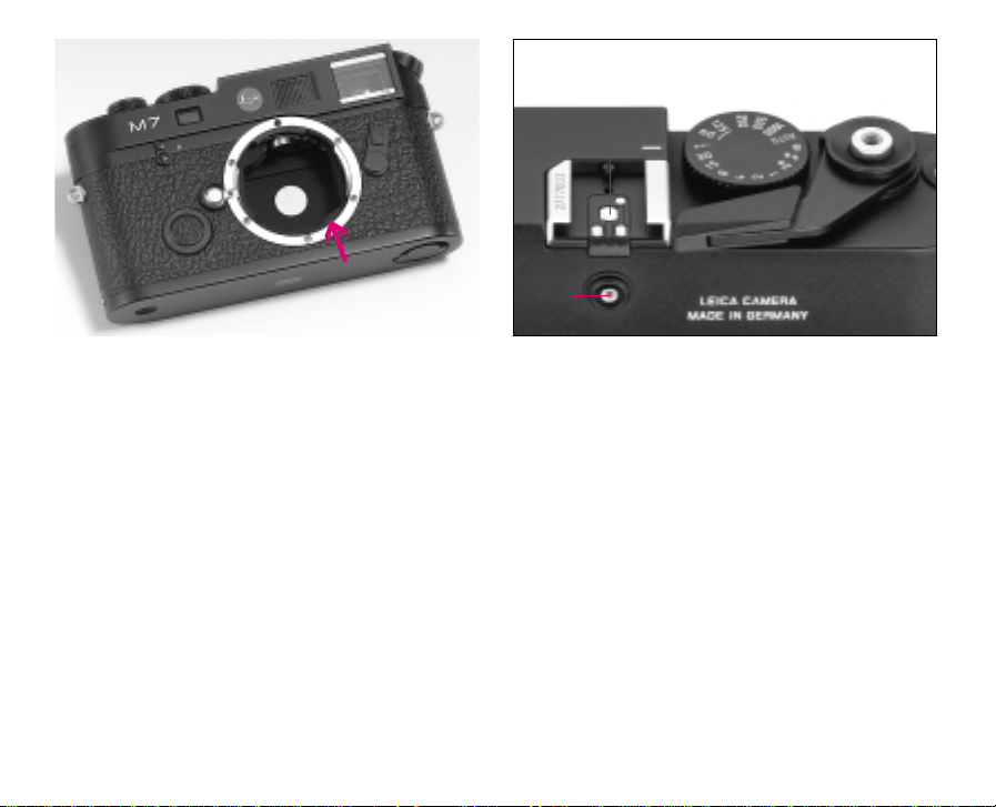
25. Tripod bushing A
/4, DIN 4503 (1/4")
26. Base plate
27. Exposure compensation scale with range of
1
±2EV in
/3EV steps
28. Exposure compensation ring with white index dot
29. Film speed dial with:
• ISO speed values from 6 to 6400 and
• DX position for automatic setting from
ISO 25/15° to ISO 5000/38°
68
Page 10
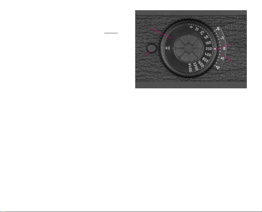
30. Release button for exposure compensation
C (75 mm)
C (50 mm)
A
B
D
ring
31. Base plate catch
32. DX contact strip
33. Schematic diagram for inserting the film
34. Coupling for motorised film transport
35. Take up spool
36. Contacts for transfer of the selected film
speed setting mode – automatically using
DX code or manually, or the manually set
film speed and any exposure compensation
set
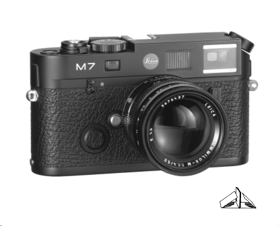
Viewfinder displays
A. Using LEDs (Light Emitting Diodes)
Four-digit seven segment digital display with
decimal point and raised point (with automatic brightness control, adjusted to the outside
1
brightness
) for:
• Display of the automatically or manually
set film speed,
• Reference to any exposure compensation
set,
• Display of the automatically controlled
shutter speeds in aperture priority mode,
• Reference to the use of exposure memory
lock,
• Warning of over or under exposure or
being below the measuring range in aperture priority mode
• Run-up of shutter speeds slower than 1s
and
• indication of battery level
Two triangular and one circular LED:
• Jointly as a light balance for manual exposure adjustment and for
• Warnings when below the metering range.
Flash-shaped LED:
• Flash status
B. Bright-line frame for 50mm and 75mm
(Example)
C. Metering field for focusing
B (75 mm)
1
Earlier Leica M lenses with additional viewfinder optics for adjustment of the image field size cover the
outside brightness sensor in the viewfinder window,
limiting the automatic control.
B (50 mm)
C
69
Page 11
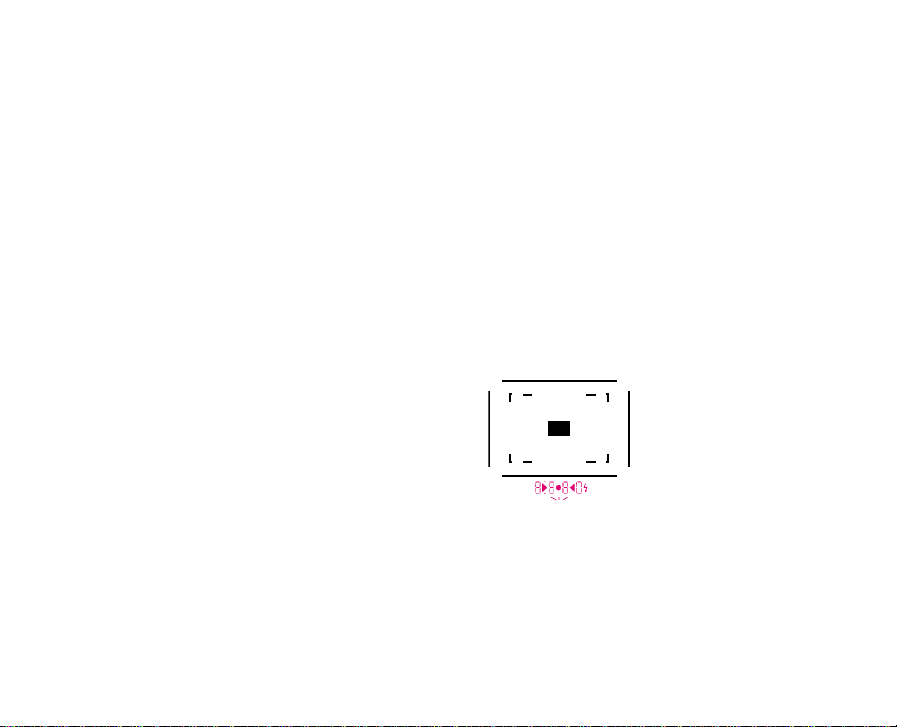
Attaching the carrying strap
!
70
Page 12
The power supply
To control the shutter – apart from the two mechanical and therefore permanently available
shutter speeds of 1/60s and 1/125s – and for
exposure metering, the LEICA M7 requires two 3
1
volt DL
/3N type lithium batteries. They are also
necessary for the electronical triggering of a
connected flash unit.
Lithium batteries can be stored for many years
with only a slight loss of power. This is a particular
advantage if the camera is often not used for long
periods of time.
Compatible batteries
1
Lithium cells - Duracell DL
- Kodak K 58 L - Philips CR
- Ucar 2 L 76 - Varta CR
1
1
/3N
/3N
/3N
Loading and replacing the batteries
01. Release the bayonet lock on the battery com-
partment cover (2) by turning it to the left (approx. 40° anti-clockwise) and remove it.
02. Wipe any oxidation residue from the batteries
using a clean cloth.
03. Insert the first battery into the battery com-
partment with the minus pole pointing upwards (corresponds to the markings in the
battery compartment) and push it upwards.
Then insert the second battery in the same
e
p
n
O
C
e
l
s
o
position in the remaining section of the compartment.
Note: To allow easy removal, the contact spring
presses the lower battery slightly towards the
cover. The final position of the batteries is only ensured by replacing the cover.
04. Replace the cover against the spring pressure
and lock it into place by turning it to the right
until you feel it click into place.
05. To remove the batteries, carry out these steps
in reverse. The upper battery will slide downwards by itself when the camera body is in a
vertical position. To assist this, you can lightly
tap the camera on your hand.
71
Page 13
At room temperature and measurements of 10s
per exposure, a new set of batteries should last
for approximately 65 36-exposure films, or 2340
exposures.
Automatic battery check
If the decimal display LEDs or the light balance
flash when exposure metering is activated, the
batteries should be replaced. If the batteries do
not have sufficient power for the electronically
controlled functions of the camera (exposure metering and the electronic shutter speeds), "
bbcc
lights up or the displays disappear altogether.
In these cases, you can continue to use the
camera with the two mechanical shutter speeds
of 1/60s and 1/125s available and exposure
metering based on estimation or using an external
hand exposure meter.
Note: The electrical circuit can be broken by
oxidation of the battery surfaces; this will also
cause the LEDs to go out. In this case, remove the
batteries and clean them with a clean cloth. If
necessary, also clean the contacts inside the camera.
Important!
• New and used batteries, or batteries of dif-
ferent types or from different manufacturers,
should not be used together.
• The battery contacts must be kept clean.
• Batteries should not be incinerated, recharged,
opened, dismantled or heated.
• Used batteries should be removed as soon as
possible and should not be disposed of in
normal waste, as they contain substances
harmful to the environment.
• To ensure that they are properly recycled, you
should take the batteries to a dealer or recycling point.
• Batteries should be stored in a cool dry place.
”
72
Page 14
9
8
ab
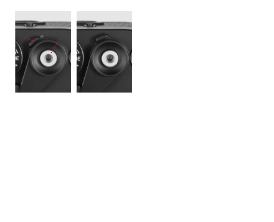
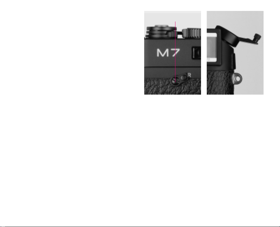
The main switch
The main switch (9), designed as a click-stop
lever, is on the front underneath the shutter
release button (8). To turn on the camera, move
the lever to the right, to cover the red marking (b).
In its idle position, i.e. when it is to the left and
the red marking is visible (a), it turns off the
camera electronics and, at the same time, mechanically blocks the shutter release to prevent
accidental exposures.
If the shutter is cocked when turning on, the
exposure meter is also activated. Initially, the film
speed is displayed or flashes in the viewfinder for
2s (depending on the setting, for more details see
the section "Film speed displays in the viewfinder”
on page 80/81). The display then changes and the
the exposure meter results light up for 14s. If the
shutter is not cocked when turning on, there is no
display.
In manual mode the shutter can be released immediately after the main switch is turned on;
when set to aperture priority mode you must wait
approx. 2s (until the film speed display has gone
out).
Note: If the camera is being transported in a bag,
for example, or will not be used for a long period,
it should be turned off at the main switch.
The shutter release button
The shutter release button (8) has two pressure
levels. Pressing it down lightly to the first pressure
point activates exposure metering if the shutter is
cocked. After the shutter release button is released, the metering system and the display in the
viewfinder remain active for approx. another 14s
(for more details see the sections under "Exposure metering” on page 96).
With the aperture priority mode, pressing down to
the 2nd pressure point locks the metered exposure value, i.e. the shutter speed determined by the
camera (for more details see the section
" Metering memory-lock ” on page 98).
Going past the 2nd pressure point releases the
shutter.
73
Page 15
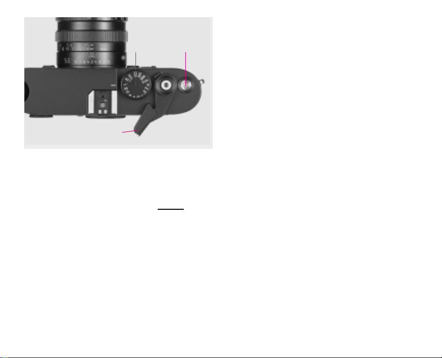
11
10
7
The shutter release button should be pressed
gently – not jerkily – until the shutter opens with a
quiet click. The shutter release has a threaded
socket to accept standard cable releases.
Note: The second pressure point canno
t be de-
tected when using cable releases.
The shutter speed dial
The size and position of the shutter speed dial (11)
on the LEICA M7 are ergonomically perfect: on
the one hand it is extremely easy to operate even
with the camera held to the eye. On the other
hand, it is still well-protected against the settings
being accidentally changed.
In addition, the direction in which it turns
(like that of the aperture ring on the lenses)
corresponds to the exposure meter displays in the
viewfinder for manual setting: for example, if the
left-hand triangular LED lights up, turning the dial
in the direction of the arrow, i.e. to the right, leads
to the slower shutter speed required.
The LEICA M7’s shutter speed dial is used to select the two exposure modes – aperture priority
mode by setting it to the "AUTO” position marked
1
in orange or red
, manual mode by selecting one
of the shutter speeds from 1/1000s to 4 s, the
sync speed 1/50 s for flash mode in the ""
1
position marked in orange or red
, or "B” for long
time exposures. When the dial is set to "B”, the
shutter remains open for as long as the shutter
release button is depressed.
In aperture priority mode, the exposure is controlled automatically and continuously, with shutter speeds in the range from 1/1 000s to 32 s.
These shutter speeds, like most of those set
manually, are created electronically, which means
they are only available if there is sufficient power
(more information can be found in the section
"The power supply” on page 71).
1
To ensure optimum visibility, these engravings are in
orange on black chromium plated cameras and red on
silver chromium plated cameras.
74
Page 16

By contrast, the shutter speeds of 1/60s and
1/125s, which can be selected in manual mode
and are additionally identified by a white line engraved next to the values, are created mechanically and are therefore always available, i.e. even
with no power supply.
Note: The click-stops for the electronic and mechanical shutter speeds differ distinctively when
engaging, i.e. between the "" and 1/60s or
1/125s and 1/2150s positions. This is determined by mechanical adjustment of a lever and is
therefore normal.
The LEICA M7 shutter speed dial does not have a
stop, i.e. it can be turned in any direction from any
position. It engages at all engraved positions; this
can be felt particularly at the "AUTO” position.
This ensures that the settings can easily be detected even without a visual check, e.g. with the
eye to the viewfinder, and prevents accidental adjustment. Intermediate speeds cannot be used.
Due to the changeover between electronic and
mechanical control or vice versa, the distances
between the "" position (1/50s) and 1/60 s or
1/125s and 1/250s are slightly greater than
those between all other settings.
For more details on setting the correct exposure,
see the sections under "Exposure metering” on
page 96.
The quick-wind lever
The quick-wind lever (10) is used to advance the
film, to cock the shutter and to automatically
advance the frame counter. The film can be transported either by moving the lever as far as it will
go or by several short strokes. For rapid sequences, you can put the lever into a "ready position”
or leave it in that position.
75
Page 17
31
1
35
36
3334
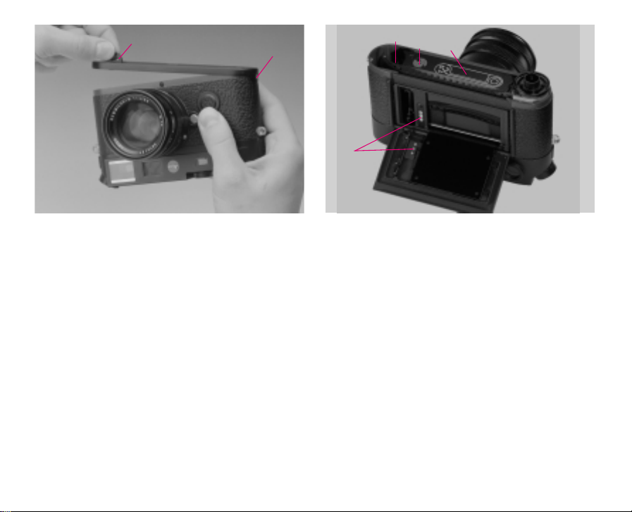
Exchanging the film
Always start by making sure that there is no film
already in the camera by turning the rewind crank
(15) gently in the direction of the arrow. If there is
any resistance, proceed as described on page 78.
Hold the camera in your right hand with the base
plate pointing upwards
Opening the camera
01. Raise the latch (31) on the base plate (26),
02. turn it to the left,
03. remove the base plate, and
04. fold the back (24) out towards the rear.
Note: With the back of the camera open, three
contacts (36) for transmission of the set film
speed to the camera’s controls can be seen on the
back and inside the camera housing. These
contacts are gold-plated and are therefore corrosion free and, as far as possible, insensitive to dirt
and dust. Special care of these contacts is not
required.
However, when loading a film, you should ensure
that soiling or direct exposure to rainwater etc. is
prevented.
This also applies to the DX contacts (32) in the
film cartridge chamber.
76
Page 18
Notes:
• The film leader must be trimmed as is the case
with all ready to use films.
• If the film leader is pulled so far out that it pro-
trudes slightly from one of the slits on the opposite side of the take up spool; this does no
affect the functioning of the camera. It is only in
frosty conditions that the film must be inserted
exactly as shown in the schematic drawing, i.e.
the film leader may only be taken up by one slit
on the take up spool so that the protruding end
of the film cannot be broken off.
Loading the film
05. Hold the film cartridge in the right hand and
insert it about half-way into the empty chamber
Note: The cartridge is pushed past the springloaded DX contacts during loading. The principle
of this means that you will feel slight resistance.
06. Take the film leader and pull it until it is in the
take up spool (35) as shown in the schematic
diagram (33) on the inside of the camera
housing, and
07. carefully press the film cartridge and the film
leader into the camera with your fingertips.
Important!
Correct film transportation should not
be checked with the camera open, as the base plate is designed in such a way that replacing it on the
camera guides the film into the correct position.
Closing the camera
08. Replace the camera back,
09. hook the base plate onto the retaining pin on
the side of the camera (1),
10. return the base plate to its normal position,
ensuring that the camera back is completely
pressed against it so that it is enclosed by the
base plate, and
11. lock using the latch.
77
Page 19
Advancing the film to the first frame
12. Advance the film to the next frame by means
of the quick-wind lever (10), and release the
shutter.
13. Pull the film taut by carefully turning the
rewind crank (15) in the direction of the arrow.
The film is being properly transported if the
rewind crank turns in the opposite direction to
the arrow when the quick wind lever is operated again.
14. Finally, release the shutter again and cock the
shutter for a third time. The frame counter (7)
now shows "1” and, after checking or setting
the film speed (29), the camera is ready to
use.
6
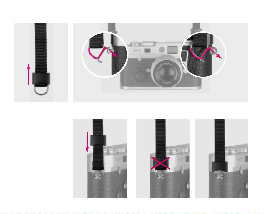
Rewinding and removing the film
When the last frame has been exposed, the quickwind lever can no longer be operated. Before the
film can be removed, it must be wound back into
the cartridge. To do this:
01. Turn the rewind release lever (6) to "R”,
02. swing out the rewind crank, and
03. turn the crank clockwise (in the direction of
the arrow) until you feel slight resistance and
the film is then freed from the take up spool.
04. Now open the base plate,
05. open the camera back, and
06. remove the film cartridge.
78
Page 20
Note: Because of the spring-loaded DX contacts,
which press onto the film cartridge, you will feel
slight resistance when removing the cartridge
from the camera. If necessary, you can lightly
tap
the camera on your hand to assist you.
If a film is not correctly attached to the cartridge
reel, e.g. when using bulk film, the end of the film
may become separated and have to be detached
from the take-up spool.
To do this:
01. Remove the base plate of the camera in a com-
pletely dark room,
02. hold the camera with the base plate open and
facing downwards, and
03. slowly operate the quick-wind lever several
times until the film protrudes far enough to be
grasped and pulled out. If necessary, gently
tap the camera against the palm of your hand.
29
28
30
27
Setting the film speed
The dial (29) is used to select the desired type of
film speed setting – automatically in the DX position or manually by setting one of the values on
the scale between ISO 6/9° and 6400/39°. In
the DX position, the film speed is automatically
scanned from the film cartridge in the range ISO
25/15° to 5000/38°. (ISO is the international
designation for film speeds).
To set the speed, the locking dial is turned so that
the desired setting – DX or the desired value – is
opposite the white index dot on the exposure
compensation dial (28).
79
Page 21

The following settings are possible
The section with a grey background represents
the speeds that can be set automatically by DX
code.
Scale Film speed Scale Film speed
6/9° 116/9° 1200/24° 1200/24°
- 11 8/10° - 1250/25°
- 1 10/11° - 1320/26°
12/12° 112/12° 1400/27° 1400/27°
- 1 16/13° - 1500/28°
- 1 20/14° - 1640/29°
25/15° 125/15° 1800/30° 1800/30°
- 1 32/16° - 1000/31°
- 1 40/17° - 1250/32°
50/18° 150/18° 1600/33° 1600/33°
- 1 64/19° - 2000/34°
- 1 80/20° - 2500/35°
100/21° 100/21° 3200/36° 3200/36°
- 125/22° - 4000/37°
- 160/23° - 5000/38°
6400/39° 6400/39°
Film speed displays in the viewfinder
Depending on the film loaded, the film speed setting and the exposure correction setting, different
displays light up or flash in the viewfinder for 2s
each time the camera is turned on with the main
switch, before the normal exposure meter displays then appear.
If the camera electronics detect an incorrect setting, the following display flashes to warn you: For
example, if the dial is set to "DX” but no DX-coded
film is loaded or a film with damaged or unreadable identification, "
110000
” flashes as an indication
that the exposure control is assuming a film speed
of ISO 100/21°. By contrast, if the dial is set to an
invalid position between "DX” and the manual val-
AASSAA
ues, "
” flashes for the entire display duration
of 16s, i.e. the exposure metering is not displayed.
In this case, exposure is once again as for
ISO 100/21°.
The table on the next page lists the different
operating statuses in detail.
80
Page 22

The set, displayed and used film speed
Film type
loaded setting compensation for exposure
1
Film speed Exposure Viewfinder displays Value used
set first 2s remaining 14 s
2
metering
DX DX No DX value exp. met. display DX value
Yes DX value flashes exp. met. display, result. value (DX+
lower pt. flashes exp. comp. value)
DX No DX value exp. met. display, DX value
manual,
equal to DX value
Yes DX value flashes exp. met. display, result. value (ISO-+
lower pt. flashes exp. comp. value)
3
DX manual, No/Yes DX value flashes
not equal to DX value
exp. met. display, set / result. value
lower pt. flashes (ISO -+ exp. comp.
value
non-DX manual No set value exp. met. display, set value
lower pt. flashes
Yes result. value
4
exp. met. display, result. value (ISO-+
lower pt. flashes exp. comp. value)
non-DX DX No/Yes "
110000
" flashes exp. met. display, ISO 100 /result.
lower pt. flashes value (100+ exp.
comp. value
DX or non-DX incorrect, between Yes/No "
AASSAA
" flashes "
AASSAA
" flashes ISO 100
the sections
1
Non-DX also applies to DX-coded films, for which the camera cannot read the
DX identification, e.g. due to damage or soiling.
2
Different displays at low battery power (see also the section "Automatic
battery check” on p. 72 for details).
3
Does not flash if set ISO-speed plus compensation value equals DX-value.
4
High speed values along with the compensations may result in effective ISO
values greater than 8000 (e.g. ISO 6400/39° +
i.e. five-digit values, that cannot be shown by the four-digit display. In such
cases, the first four digits of the resulting value are shown, with the right zero flashing to show that there is a "missing” zero, e.g. for the above example
00
11 0000
”.
"
2
/3EV => ISO 10000/41°),
81
Page 23

Setting an exposure compensation
Exposure meters are calibrated to an average grey
(18% reflection), which corresponds to the brightness of a normal, i.e. average, photographic subject (for more details see the section "General
information on exposure metering” on p.106).
If the relevant subject details do not meet these
requirements, a corresponding exposure compensation can be carried out.
Particularly for several shots one after the other,
e.g. if a series of shots with a slightly lower or
higher exposure is deliberately required for a
particular reason, exposure compensation is a
very useful function. In contrast to metering
memory-lock, once set it remains effective until it
is (deliberately) reset (more details of metering
memory-lock can be found in the appropriate section on page 98).
With the LEICA M7, exposure compensations can
1
be set at
/3EV intervals in the range ±2 EV.
To do this:
1. Hold down the release button (30), and
2. then turn the locking dial (28) so that its
white index dot is opposite the desired
compensation value on the scale (27).
The whole range of possible compensations of
±2 EV can be used for all engraved film speeds.
Overall, the resulting extended setting range
makes it possible to use speeds from ISO 1.5/3°
to ISO 25000/45°.
Any exposure compensation set is indicated in the
camera’s viewfinder, see the table on page 81 for
details.
Note: Any exposure compensation set on the
camera influences both the metering of the
available light and the TTL flash exposure metering.
82
Page 24

Example of a compensation to plus
For very bright subjects, e.g. snow or a beach, the
exposure meter will give a relatively short exposure time due to the high level of brightness. This
reproduces the snow as a mid-grey and any people in the scene are too dark: this is under-exposure! To remedy this, the exposure time must be
extended or the aperture opened, i.e. with a setting of e.g. +1.5.
Example of a compensation to minus
For very dark subjects, which do not reflect much
light, the exposure meter will give an exposure
time that is too long. A black car will turn grey: this
is over-exposure! The exposure time must be
shortened, i.e. with a setting of e.g. –1.
83
Page 25

Attaching a lens
01. Hold the lens by the fixed ring (17),
02. align the red lens alignment button (5) with
the lens release button (3) on the camera
body,
03. attach the lens in this position, ensuring that
it is perpendicular to the front of the camera,
and
04. turn the lens slightly to the right to lock it
audibly and perceptibly into place.
Removing a lens
01. Hold the lens by the fixed ring (17),
02. depress the lens release button (3) on the
camera,
03. turn the lens to the left until the lens align-
ment button (5) lines up with the lens release
button, and
04. remove the lens, keeping it perpendicular to
the camera body.
Note: When the camera is loaded with film,
change the lens in the shade of your body, as
direct sunlight may otherwise penetrate the
shutter.
84
Page 26

20
19
18
17
Leica M lens design
The Leica M lenses are equipped with a fixed ring
with an index for setting the distance, an alignment button for changing the lens and the depth
of field scale (17), a rotating focusing ring (18) and
an aperture setting ring (19) with associated
white index point (20).
The focusing ring
The focusing ring (18) shows the distance set and,
in conjunction with the scale (17), the depth of
field range. For details on focusing, see the "The
rangefinder” section on page 94.
85
Page 27

The aperture ring
The aperture values are standarised world-wide.
They are selected such that the amount of light
reaching the film is always halved when the lens is
stopped down between two successive apertures
(stops) One stop corresponds to one value on the
shutter speed dial (11).
As for the shutter speeds for manual setting, the
aperture ring (19) engages perceptibly at each full
stop (and on most lenses also at half stops). With
a little practice, you will also be able to set the
apertures in the dark.
The direction in which the aperture ring turns
(like that of the shutter speed dial) corresponds to
the exposure meter displays in the viewfinder for
manual setting.
For example, if the left-hand triangular LED lights
up, turning the dial in the direction of the arrow,
i.e. to the right, leads to the slower shutter speed
required.
For more details on setting the correct exposure,
see the section: "Exposure metering” on page 96.
86
Page 28

The depth-of-field scale
The plane which is rendered sharpest is the plane,
parallel to the film, upon which the lens is focused. The optimum sharpness decreases progressively in front of and behind this plane so that
a certain range exists within which the image is, to
the eye, rendered sharply.
This range is termed the depth-of-field. It is dependent on the focus setting, the focal length of
the lens (the two values together determine the
reproduction ratio) and the aperture. Stopping
down, i.e. selection of a larger f-number, increases
depth-of-field, while opening the aperture, i.e.
selection of a smaller f-number, decreases it.
The depth-of-field scale in conjunction with the
focusing ring indicates the range of sharpness at
the set focus distance.
For example, using the LEICA SUMMILUX-M
50mm f/1.4 lens focused at 5 meters, the depth
of field at f/4 ranges from approximately 4 to 8
meters. Stopping down to f/11 at the same focusing distance, however, increases the range to
3-20 meters.
87
Page 29

Lens hoods
Each Leica M lens is supplied with a lens hood the
design of which is geared to the lens. Several lenses have built-in telescopic lens hoods. The lens
hoods should always be used as they provide both
shade from stray light and glare and protection
against raindrops or fingerprints.
Use of older Leica M lenses
All Leica M lenses can be used. However, the
exposure metering system does not function with
the following types:
Hologon 15mm f/8
Super-Angulon-M 21mm f/4
Super-Angulon-M 21mm f/3.4
Elmarit-M 28mm f/2.8
up to Serial No. 2314921.
The following lens must be set to infinity during
fitting/removal:
Summicron 50mm f/2 with close focusing.
88
Page 30

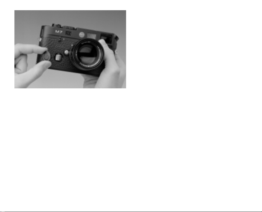
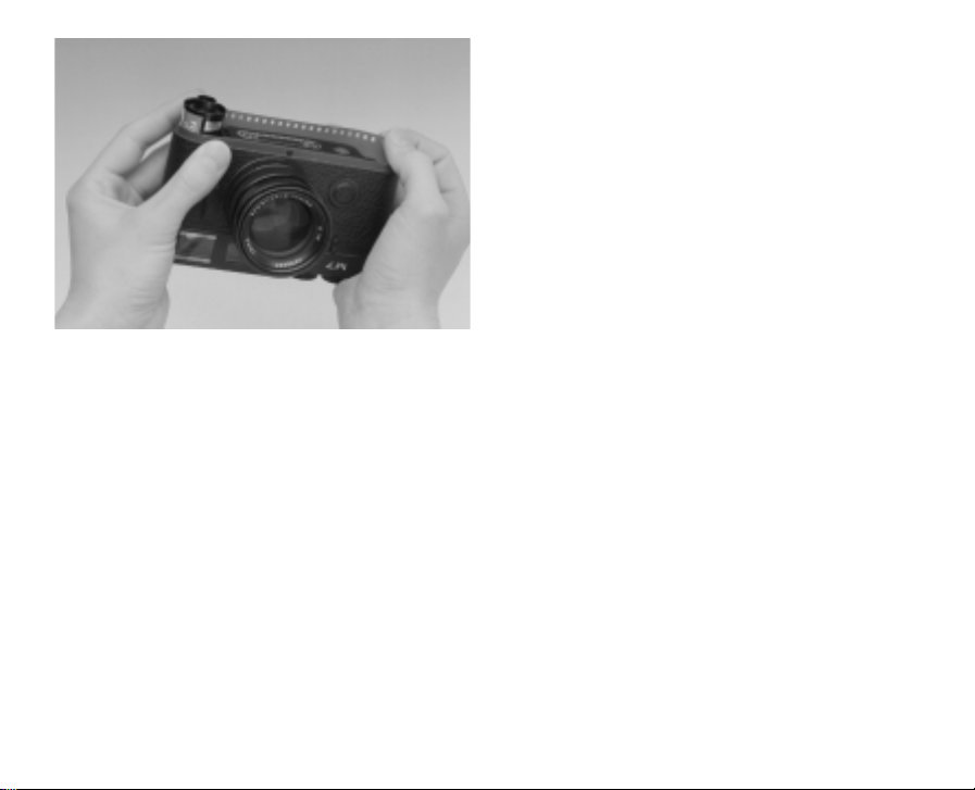
How to hold the camera correctly
In order to achieve sharp, well-focused photographs, the camera must be held as steadily and
comfortably as possible. Hold the LEICA M7 in a
suitable, safe "three-point holding position” as
follows: hold the camera with your right hand with
your index finger on the release button and with
your thumb pushed behind the quick-wind lever in
its operating, standby position. Press the camera
against your forehead and cheek to give it further
stability.
For vertical pictures, turn the LEICA M7 to the left
and keep your hands in the same position as for
horizontal shots. You can however also rotate the
camera to the right. In this case, it may be advantageous to release the shutter using your
thumb
Note: We recommend the practical Handgrip M
(accessory) to enable you to hold the LEICA M7
and to carry it securely while keeping your hands
free (order No.14405).
89
Page 31

The bright-line viewfinder
The bright-line viewfinder of the LEICA M7 comprises not only a high-quality, large, bright and
high-contrast viewfinder showing every detail
which will appear on the final picture, but also a
highly accurate lens-coupled rangefinder.
The size of the frame corresponds to an image
field of 23 x 35mm (slide format) at the closest
focusing distance for each lens. At longer
distances, the image will contain a somewhat
larger subject field than that shown within the
bright-line frame.
The frames are coupled to the focusing mechanism such that parallax errors (the distance
between lens and viewfinder axes) are automatically compensated for as the lens is focused, and
the bright-line frame is the same as the film
image in the entire range from 0.7m to ∞.
Three LEICA M7 models are available with different versions of this viewfinder; the only difference
is in their magnification:
When lenses with focal lengths of 28 (Elmarit from
serial No. 2411001 onwards), 35, 50, 75, 90 and
135mm are used on the LEICA M7 with 0.72x
viewfinder magnification, the corresponding
bright-line frame is automatically reflected into
the viewfinder in the combinations 28+ 90 mm,
35 +135mm and 50 +75mm.
When the LEICA M7 is used with the higher 0.85x
viewfinder magnification, five frames are reflected into the viewfinder for the focal lengths from
35mm upwards (90mm, 35+135mm, 50 +75mm).
In the LEICA M7 0.58 five bright-line frames for
the focal lengths up to 90mm (28 + 90 mm,
35mm, 50+75mm) are projected into the viewfinder.
The center of the viewfinder contains a somewhat
brighter rectangle: this is the rangefinder. All
lenses with focal lengths from 21 to 135mm
couple to the rangefinder when attached to the
LEICA M7.
With the exposure meter switched on, the lower
edge of the viewfinder also displays the LEDs of
the exposure meter or the LED flash symbol.
For more details on distance and exposure metering and flash modes, refer to the corresponding
sections on pages 94/96/108.
Note: On the LEICA M7 0.85, the central section
of the lower 50mm bright-line frame is covered by
the display.
90
Page 32

Bright-line
frame
35 mm
Bright-line
frame
135 mm
LEDs for shutter/aperture balance
Metering field
for focusing
91
LED for flash operation
Page 33

The frame selector
The frame selector lever (21) extends the possibilities of the LEICA M7 viewfinder. Using this integrated
universal viewfinder, you can view frames which
do not correspond to the lens which is actually fitted. Thus, you can test whether the composition
would be better served by a different focal length.
When the lever is pointing outwards, i.e. away
from the lens, the frames for the 35 and 135mm
focal lengths are displayed (the bright-line frame
for the 135mm focal length is not included in the
viewfinder of the LEICA M7 0.58).
When the lever is in its vertical, central position,
the frames for the 50 and 75mm focal lengths are
shown.
When the lever is pointing inwards, i.e. towards
the lens, the LEICA M7 viewfinder displays the
frames for the 28 and 90 mm focal lengths (the
0.85 x magnification viewfinder only shows the
bright-line frame for the 90mm focal length).
35 mm +
135 mm*
* not for LEICA M7 0.58
92
Page 34

50 mm + 75 mm
28 mm * +
90 mm
* not for LEICA M7 0.85
93
Page 35

The rangefinder
Thanks to its high effective base width, the
rangefinder of the three LEICA M7 models permit
very precise control. This is particularly advantageous when wide-angle lenses, which provide a
relatively large depth of field, are used. The larger
magnification of the 0.85x viewfinder with its
longer base width leads to even higher accuracy:
Mechanical base width x Viewfinder = Effective
(distance between magnification base width
the optical axes of
the viewfinder
and the rangefinder
LEICA M6 TTL
with 0.72x approx.
viewfinder 69.25 mm x 0.72 = 49.9mm
LEICA M6 TTL
with 0.85x approx.
viewfinder 69.25 mm x 0.85 = 58.9mm
LEICA M6 TTL
with 0.58x approx.
viewfinder 69.25 mm x 0.58 = 40.2mm
window)
The rangefinder field is the bright rectangle in the
center of the viewfinder field. If you cover up the
large viewfinder window (16), only the bright-line
frames and the rangefinder field remain visible.
The bright, sharply defined rangefinder field permits the use of either coincidence or split-image
rangefinder focusing.
Coincidence (double image) focusing
For a portrait, for example, align the eye with the
rangefinder field and turn the focusing ring of the
lens until the contours in the rangefinder field
merge. You can now determine the subject composition.
Split-image focusing
For photographs of architecture or other subjects
with straight vertical lines, align those vertical
lines with the rangefinder field and turn the focusing ring of the lens until the contours form a continuous line at the limits of the rangefinder field.
You can now determine the subject composition.
In practice, there is rarely a clear distinction
between the two methods. It can be very effective
to use a combination of the two.
94
Page 36

Double image = out of focus
Coincident image = in focus
Interrupted line = out of focus
Continous line = in focus
95
Page 37

The irregular structure of the metering field in no
ways affects the meter reading.
The viewfinder displays show or help to determine
the appropriate speed/aperture combination for
correct exposure: When using the aperture priority mode, the aperture is selected manually, while
the camera automatically calculates the appropriate shutter speed. In this mode, a digital
LED display provides information on the resulting
shutter speed (e.g.
11000000
).
For manual setting of both values, a light balance
consisting of three red LEDs () is used to
balance the exposure. When the setting is correct,
only the central, circular LED is lit.
Exposure metering
On the LEICA M7 exposure metering uses the
available ambient light selectively through the
lens at the working aperture. The reading uses
light reflected from a bright metering field onto a
photo diode (arrow). This diode is located behind
a collecting lens to the left of and above the shutter. The metering field (diameter:12mm, i.e. approx.13% of the negative’s size) is situated in the
center of the first shutter curtain. The unevenness
of the white is not a result of poor manufacturing
tolerances, but is due to the fact that a thick, complete coating cannot be applied to the rubberised
cloth shutter curtain without the shutter performance being impaired.
Switching on the exposure meter
The exposure meter is turned on by lightly pressing the shutter release button (9) to its first pressure point, assuming that the camera is turned on
with the main switch (8), the shutter is fully
cocked and the shutter speed dial (12) is not set
to "B”.
Constant illumination of one of the displays in the
viewfinder indicates that the exposure meter is
ready for use:
- the digital shutter speed LED display for aper-
ture priority mode
- one of the two triangular LEDs, possibly com-
bined with the central circular LED, for manual
setting.
96
Page 38

If the finger is released without the shutter being
depressed, the exposure meter remains switched
on for approx. 14s and the corresponding LED(s)
remain on. When the shutter is activated, the
meter switches off and the LEDs in the viewfinder
go out.
If the main switch is not turned on (i.e. the camera
is turned off) and/or the shutter is not cocked
and/or the shutter speed dial is set to "B”, the
exposure meter is turned off.
The exposure modes
The LEICA M7 offers photographers two exposure
modes: aperture priority mode or manual setting.
Depending on the subject, the situation and individual preferences, you can choose between the
somewhat faster and more convenient aperture
priority mode or the fixed setting of the shutter
speed and aperture familiar from other Leica M
models.
Notes: If the shutter is not cocked or the displays
have gone out, the camera is in "Standby " mode.
At very low levels of luminance, i.e. at the threshhold of the light metering range, the LEDs may
take approx. 0.2s to appear.
If it is not possible in the aperture priority mode to
create the correct exposure with the available
shutter speeds, the shutter speed display flashes
as a warning (for more details see the section "The
aperture priority automatic exposure mode” on
the right).
If manual setting at very low luminance goes below the measuring range of the exposure meter,
the left-hand triangular LED flashes as a warning.
For the aperture priority mode, the shutter speed
continues to be shown. If the necessary shutter
speed falls below the slowest possible speed of
32s, this display also flashes.
The aperture priority automatic exposure mode
With the shutter speed dial (11) set to the "AUTO”
position, which engages particularly firmly, the
camera electronics automatically generate the
appropriate shutter speed continuously in the
range from 1/1000s to 32s, depending on the
film speed, either read via DX code or set manually, the measured brightness and the manually
selected aperture.
As a result the aperture priority mode is particularly well suited for shots for which you prefer to
make less settings and where the depth of field
has to be set according to composition needs. The
automatically generated shutter speed can, if
necessary, be changed by adjustment of the
aperture, e.g. to create certain "wiping effects”
with slower shutter speeds or to "freeze” movements with faster shutter speeds.
97
Page 39

The shutter speed calculated is displayed digitally
in the camera’s viewfinder, in half steps to give a
better overview.
For shutter speeds of 2s and slower, the remaining exposure time is counted down in the
display after the shutter is released. However, the
exposure time actually calculated and continuously controlled can deviate from the half-step
value shown. If, for example, "
1166
” (as the nearest
value) is shown in the display before the shutter is
released, but the calculated exposure time is
longer, the countdown after release could also
start from "
1199
”.
Under extreme light conditions, after calculating
all the parameters, the exposure meter can arrive
at shutter speeds outside its working range, i.e.
brightness values, which would require exposures
shorter than 1/1000s or longer than 32s. In such
cases, the minimum or maximum shutter speed
mentioned is used and the value flashes as a
warning.
Metering memory-lock
It is often the case that, for composition reasons,
important parts of the subject should be offcenter and these important parts of the subject
are sometimes brighter or darker than average.
However, as described in the sections "Exposure
metering” on page 96 and "General information
on exposure metering” on page 106, the selective
metering of the LEICA M7 deals exclusively with
the center of the image and is calibrated to an
average grey.
The aperture priority mode provides an easy way
of dealing with this kind of subject and situation
with metering memory-lock.
To do this:
01. Focus the metering field on the important part
of the subject, in the first case, and on another
detail of average brightness in the second
case, by moving the camera (see also the
illustrations for aligning the metering field in
the viewfinder on pages 104/105),
02. and then press the shutter release button (8)
to its second pressure point to measure and
lock the value. As long as the pressure is
maintained, a red point appears in the viewfinder at the top of the numerical line as
confirmation and the speed value does not
change, even if the brightness conditions do so.
0
98
Page 40

03. Continuing to hold down the shutter release
button, move the camera to the final picture
detail,
04. and then you can release the shutter with the
original exposure calculated.
Changing the aperture setting after the measured
value is locked does
not result in adjustment of
the shutter speed, i.e. it would lead to incorrect
exposure.
Memory-lock ends when the finger is removed
from the pressure point of the shutter release button.
Note: When using the camera with a motorised
drive, e.g. LEICA MOTOR M, metering memorylock can only
be used for individual exposures, not
for a series of exposures.
Setting the exposure manually
To set the exposure completely manually, the
shutter speed dial (11) must be set to one of the
engraved shutter speeds.
Then:
01. Turn on the exposure meter,
02. turn the shutter speed dial and /or the aper-
ture ring on the lens in the direction indicated
by the flashing LED until only the round LED
comes on.
In addition to the direction of rotation of both
shutter speed dial and lens aperture ring required
for correct exposure, the three LEDs of the light
balance also indicate over-, under- and correct
exposure as follows:
Underexposure by at least one f-stop; turn
clockwise.
Underexposure by half an f-stop; turn
clockwise.
Correct exposure
Overexposure by half an f-stop; turn
anticlockwise.
Overexposure by at least one f- stop; turn
anticlockwise.
Note: For shutter speeds slower than 2s, the remaining exposure time is counted down in the
display after the shutter is released.
99
Page 41

The "B" setting
The "B" setting, at which the shutter remains open
for as long as the shutter release button is depressed, allows exposures of any length.
The exposure meter remains turned off, however
the digital numerical display counts the expired
exposure time in seconds after the shutter is released. To preserve the batteries, the maximum
count and display is “
999999””
. After this, the display
goes out, but the shutter can nevertheless remain
open for as long as required.
Note: With the "B" function, batteries are still re-
quired to open and close the shutter. However, for
the entire duration of the exposure, the open shutter does not consume any power, only a small
amount of battery power is required for the
camera control.
Meter sensitivity
At room temperature, normal humidity and an
aperture of 1.0, the measuring range is from 0.03
2
to 125000 cd/m
. For ISO 100/21° this corresponds to EV-2 to 20 or f/1.0 and 4s to f/ 32 and
1/1000s (see also diagram on page 103).
Light levels below the measuring range
If manual setting at very low luminance goes
below the measuring range of the exposure
meter, the left-hand triangular LED flashes as a
warning. For the aperture priority mode, the shutter speed continues to be shown. If the necessary
shutter speed falls below the slowest possible
speed of 32s, this display also flashes.
Since the meter uses the working aperture, the
LEDs may also flash when the lens is stopped
down.
The exposure meter remains on for approximately
14 seconds after finger pressure is removed from
the shutter release button, even if the light level is
below the threshold sensitivity level. If the light
level improves during this time (e.g. if the composition is changed or the diaphragm opened), the
LEDs stop flashing and come on permanently.
100
Page 42

Switching off the exposure meter
If the camera will not be used for a long period, or
is stored in a bag, it should always be turned off at
the main switch. This stops any power consumption, including the slight consumption that continues in Standby mode after the exposure meter has
turned off automatically and the displays have
gone out. This also prevents accidental exposures.
Metering diagram (see also p.103)
The metering diagram applies to both exposure
modes, aperture priority mode and manual setting.
Details of the measuring range of the exposure
meter can be found on the right-hand side of the
diagram, while details of the working range of the
focal plane shutter can be seen on the left. The exposure values (EV) are shown in the middle.
The metering range of the exposure meter is indicated on the right-hand side of the diagram, in
2
(candela per square meter).
cd/m
The ISO film speed values (Sv) are shown at the
top of the diagram.
The different exposure speeds in seconds (Tv=
Time value) are shown on the left-hand side of the
diagram.
The working range of the LEICA M7 focal plane
shutter is represented schematically by the shaded area in the adjacent column. With the "B” set-
ting, the upper section is unrestricted.
The aperture values (Av) are shown on the lower
left-hand side.
Example A shows the correlation between the film
speed, luminance (brightness), exposure and
aperture.
First follow the vertical line from the film speed
(ISO 100/21°) down to the intersection on the
horizontal line representing the corresponding
luminance.
2
In example A, this is 4000 cd/m
, i.e. a typical
value for bright sunlight. The line now runs diagonally to the vertical line indicating the aperture
(11), and from there horizontally to the required
speed (1/250s). In the course of this diagonal
line, the exposure value (15) can also be found.
Example B shows that in candlelight and with a
2
film speed of ISO 400/27° (cd/m
), photographs
should be taken with an aperture of f/1.4 and a
shutter speed of 1/15s. An aperture of f/11, for
example, can no longer be used as the corresponding shutter speed of 4s is not available
101
Page 43

on the shutter speed dial. As the slowest shutter
speed available on the dial is only 1s, exact metering is also no longer possible. The correct shutter
speed can therefore be obtained only by conversion or from this diagram.
By contrast, with the aperture priority mode, the
LEICA M7 automatically calculates shutter speeds
up to 32s, so that in the example highlighted,
every aperture of the lens could be used.
Metering fields in the viewfinder
(see also pp. 104/105)
The metering field covers approx. 23% of the
viewfinder image for the lens being used.
However, the following reference value applies to
all lens focal lengths:
The diameter of the circular metering field is
approx. 2/3 of the short side of the applicable
bright-line frame. This also applies to lenses with
viewfinder attachments, such as the LEICA
ELMARIT-M 135mm f/2.8.
102
Page 44

Metering diagram
60
30
15
8
B
4
2
1
1/2
Tv
1/4
1/8
1/15
1/30
1/60
1/125
1/250
1/500
1/1000
1 1,4 2 2,8 4 5,6 8 11 16 22 32
Sv
ISO
6/9°
12/12°
25/15°
50/18°
100/21°
200/24°
400/27°
800/30°
1600/33°
3200/36°
6400/39°
0,03
-6
-5
-4
-3
-2
-1
0
1
2
3
4
5
6
7
8
9
10
11
12
13
14
15
16
17
18
19
20
Av
Ev
BA
0,063
0,125
0,25
0,5
1
2
4
8
16
32
63
125
250
500
1000
2000
4000
8000
16000
32000
63000
125000
cd/m
Bv
2
103
Page 45

LEICA M7
Viewfinder magnification 0.58x
LEICA M7
Viewfinder magnification 0.58x
LEICA M7
Viewfinder magnification 0.72x
21
mm
28
mm
35
mm
50
mm
104
24
mm
90
mm
135
mm
75
mm
21
mm
28
mm
35
mm
50
mm
Page 46

LEICA M7
Viewfinder magnification 0.72x
LEICA M7
Viewfinder magnification 0.85x
LEICA M7
Viewfinder magnification 0.85x
24
mm
90
mm
135
mm
75
mm
105
21
mm
28
mm
35
mm
50
mm
24
mm
90
mm
135
mm
75
mm
Page 47

General information on exposure metering
Most scenes contain an even distribution of bright
and dark subject details and reflect an average of
18% of the light falling on them. This value of 18%
corresponds to an average grey tone to which
exposure meters are calibrated. Very bright subjects, such as snow-laden winter scenes, sandy
beaches, whitewashed walls or a white wedding
gown, reflect more light toward the exposure
meter, tending to result in underexposure.
Predominantly dark subjects such as a black
steam locomotive, dark grey slate roofs, and
navy-blue uniforms reflect much less light, and
meters tend to overexpose.
This is the case unless a corresponding exposure
compensation has been set in advance or the exposure has been measured selectively using a
section of the subject containing a representative
distribution of light and dark details (for more
information see the section " Setting an exposure
compensation ” on page 82).
You would for example meter on the bride’s face
and not on her white gown. A landscape shot with
a wide-angle lens should be metered with the
LEICA M7 pointing downward to exclude the
bright sky. Metering memory-lock allows this
technique to be used conveniently even when
using the aperture priority mode (for more details
see the section "The aperture priority automatic
exposure mode" on page 97).
If there is no suitable section of the subject for
metering when setting the exposure manually, a
compensation factor must be used, i.e. the exposure time is extended by 2 to 4x or the aperture
can be opened by one or two f-stops.
White snow under a clear sky with bright sunlight
often calls for an exposure increase of 4x, i.e.
instead of the specified shutter speed of 1/1000 s
and f/8, use 1/250s and f/8 or 1/1000s and
f/4. When photographing less bright subjects
such as a sandy beach, a compensation factor
of 2 is sufficient.
The reverse is the case for dark subjects.
106
Page 48

If there is considerable contrast between light and
dark parts of the image, the exposure latitude of
the films ceases to be sufficient to register the full
tonal range of the subject in both the "light" and
the "shade". The photographer must decide
where he wishes to retain the greatest detail. For
example, a person can appear as a black silhouette (underexposed) in front of a correctly exposed
landscape, or correctly exposed in front of a
"burnt-out" background (overexposed). A reading
from "light" and "shadow" and the resulting average exposure usually leads to unsatisfactory
results because delicate differences in brightness
are lost in both the light and the dark areas.
Deliberate over- or underexposure often enhances the character of a picture and can be used as
a good compositional aid.
107
Page 49
23
13
Flash photography
In addition to the photocell for ambient light, the
LEICA M7 is equipped with a second photocell for
flash (arrow). This silicon photocell, located on the
right below the shutter, enables the camera to
measure the light emitted by the flash through the
lens, at the working aperture. The Through The
Lens flash metering system on the LEICA M7 is
center-weighted.
The LEICA M7 can meter and automatically control the flash with
• the LEICA SF24D system flash unit specially
developed for the LEICA M6TTL/M7 and
LEICA R8/R9) (Order nos. 14444, silver or
14448, black) or
• Flash units that meet the technical require-
ments of System-Camera-Adaption (SCA) for
the 3000 system and have the SCA-3502/3501
adapter.
If the flash unit used has the appropriate func-
1
, the LEICA M7 also allows other, more inter-
tions
esting compositional flash techniques to be used,
such as synchronisation of the flash to the 2nd
shutter curtain rather than the 1st as is normal,
use of the flash with faster shutter speeds than
the synchronising speed of 1/50s and strobe
flash (for more details see the appropriate sections below).
1
For flash operation on the 2nd shutter curtain and high
speed synchronised flash, the SCA 3502 adapter is required. Strobe flash, on the other hand, is possible with
the SCA 3501.
108
Page 50

The TTL-controlled flash exposure metering and
control can be used with both exposure modes.
Important!
In order to trigger and control the flash units
connected by means of the accessory shoe or the
coaxial contact (23), the LEICA M7 must be
loaded with batteries and the exposure meter
must be switched on by lightly pressing the shutter release button, i.e. the display must have been
switched to shutter speed values or the light
balance.
Compatible flash units
Thanks to its compact dimensions and its dedicated design, the LEICA SF20/SF 24D is particularly
suitable for use with the LEICA M7. It is very simple to use, as it is equipped with an integrated adapter foot with additional control and signal
contacts for automatic transfer of a range of data
and settings. It also provides a number of interesting additional functions.
You can also fit any other standard flash units with
standard connecting plugs or on-camera flash
units with standard adapter foot to the
LEICA M7, and trigger them using the center
contact (X contact, 13). We recommend the use of
modern thyristor-controlled electronic flash units.
109
Page 51

Attaching and connecting the flash unit
When mounting a flash unit on the hotshoe of the
LEICA M7, ensure that the adapter foot of the
flash unit is fully inserted and firmly secured by
means of the tightening nut, if available. This is
especially important in the case of flash units with
additional control and signal contacts, as movements of the flash unit within the adapter foot
may lead to the contact being broken and consequently to malfunctions.
The coaxial contact for connecting flash units with
cord connection is located below the accessory
shoe at the back of the camera.
Note: The camera and flash unit must both be
switched off before the flash is attached.
TTL flash mode
On the LEICA M7, this mode is available with both
exposure modes, aperture priority mode and
manual setting and can be used with the LEICA
SF20/SF 24D and any other SCA-3000 flash units
equipped with an SCA 3502/3501 adapter. As
soon as the required quantity of light has been
emitted, the camera electronics of the LEICA M7
transmit a "stop" signal to the flash unit, which
immediately interrupts light output. This flash mode
offers the advantage that all factors influencing
exposure of the film (e.g. filters and aperture
changes) are automatically taken into account.
The LEICA M7 also transmits the film speed to the
flash unit.
If the flash unit is equipped with the appropriate
displays and if the aperture selected on the lens is
manually
entered on the flash unit, it can automatically adjust its range settings accordingly. The
flash unit cannot be used to influence the film
speed setting.
Note: Since the aperture selected on the LEICA M7
is not transferred to the flash, it must be set
manually on the flash unit to enable the range to
be read off on the latter, if the flash has such a
display.
110
Page 52

Settings for TTL flash mode
After turning on the flash unit and setting it to
"TTL” mode, proceed as follows on the LEICA M7:
01. Before each flash exposure, first of all turn on
the exposure meter by lightly pressing the
shutter release button, i.e. the display must
have switched to shutter speed values or the
light balance. If the shutter release button is
pressed too quickly and completely and the
exposure meter remains turned off, the flash
unit may not be triggered.
02. Set the shutter speed dial to "AUTO", the flash
synchronising speed "" (1/50s) or, for spe-
cial effects, a slower shutter speed (or "B"). In
aperture priority mode, the camera automatically switches to the flash synchronising
speed 1/50s.
03. Set the desired aperture or that required for
the appropriate distance between camera and
subject.
Flash exposure displays in the viewfinder with
the SF20/SF24D or compatible flash units
with SCA 3502/3501 adapter
In the LEICA M7 viewfinder, an LED in the shape
of a flash (A) is used for acknowledgement and to
indicate the different modes. This LED appears
together with the displays described in the corresponding sections for exposure metering using the
available light.
Displays in TTL and automatic flash mode
• is not displayed even though the flash unit is
turned on and ready to use:
A shutter speed faster than 1/50s is manually
set on the camera, but the flash unit is not
set to the "High speed synchronised flash”
function. In such cases, the LEICA M7 does not
trigger the flash unit even if it is turned on and
ready to use.
Note: High speed synchronised flash is only possible in the flash unit’s manual mode, not for computer or TTL mode.
• flashes slowly (at 2 Hz) before the shutter is
released:
The flash unit is not operational yet.
• lights up continuously before the exposure:
The flash unit is operational.
111
Page 53

• continues to flash after exposure, however
the remaining displays go out:
Flash exposure was correct, flash remains
operational.
• flashes rapidly after exposure, however the
remaining displays go out:
Flash exposure was correct, however the flash
is no longer operational.
Displays in manual flash mode
• is not displayed even though the flash unit is
turned on and ready to use:
A shutter speed faster than 1/50s is manually
set on the camera, but the flash unit is not set
to the "High speed synchronised flash” function. In such cases, the LEICA M7 does not
trigger the flash unit even if it is turned on and
ready to use.
• goes out along with the remaining displays
after exposure:
Underexposure, for example due to an aperture
too small for the subject. If the flash unit has an
output reduction mode, a chosen lower output
can mean that the unit is still ready to use
although the flash LED has gone out.
Note: High speed synchronised flash is only possible in the flash unit’s manual mode, not for computer or TTL mode.
• flashes slowly (at 2 Hz) before the shutter is
released:
The flash unit is not operational yet.
• lights up continuously before the exposure:
The flash unit is operational.
112
Page 54

ab
Synchronisation on the 2nd shutter curtain
If the attached flash unit has the corresponding
function and an SCA-3502 adapter is being used,
the LEICA M7 allows the flash to be triggered on
either the 1st or the 2nd shutter curtain. This
makes it possible to have the – very short – flash
exposure either at the beginning or the end of the
– relatively longer – exposure with the available
light.
Particularly with subjects in dark surroundings,
which themselves emit or reflect light, e.g.
vehicles, synchronisation with the 2nd shutter
curtain often gives a more natural effect.
The function is available for all camera and flash
unit settings, for both aperture priority mode and
manual shutter speed selection, for TTL and
automatic or manual flash mode, the displays are
the same in all cases.
113
Page 55

The synchronisation is selected on the flash units
with the corresponding features. For more details,
refer to the relevant instructions.
Important!
For synchronisation on the 2nd shutter curtain,
for high speed synchronisation, and strobe flash
techniques, the camera must be activated before
exposure, i.e. the exposure metering results must
be displayed. This ensures that the necessary
exchange of data between the camera and the
flash unit can take place. It is no
t enough to
simply place the camera in standby mode with
the main switch. If the camera was not activated,
these flash modes can function incorrectly (e.g.
no triggering or full flash instead of strobe
function).
For the same reason, these flash modes should
not be used in conjunction with rapid sequences
of shots in series exposures with motor drives/
winders.
114
Page 56

High Speed Synchronisation flash mode
If the attached flash unit has the corresponding
function and an SCA-3502 adapter is being used,
the LEICA M7 allows faster shutter speeds of
1/250s, 1/500s and 1/1000s to be used for
flash exposures. This high speed synchronisation
flash technique significantly expands the creative
freedom offered for flash exposures. This is
particularly useful for daylight fill-flashes for
moving subjects, where the desired shallow
depth-of-field requires large apertures and, at the
same time, the high ambient brightness requires
fast shutter speeds.
With standard flash techniques, focal plane shutters like those in the LEICA M7 can only be synchronised with shutter speeds at which the
camera’s shutter window is completely open at a
particular point in time. For the LEICA M7, that
means all shutter speeds up to 1/50s. At faster
speeds, a section of either the 1st or the 2nd
shutter curtain is always in the shutter window,
which means that a flash can never illuminate the
entire image.
However, some modern flash units have "High
Speed Synchronisation – HSS”, which emits flashes
of lower power at very short intervals for a short
period of time. As these flashes are emitted
throughout the entire duration of the operation of
the two shutter curtains, and have the effect of a
continuous light source during this time, with this
technique the actual shutter speed is no longer so
critical.
To use the "High Speed Synchronisation flash”
technique, one of the three possible shutter
speeds 1/250s, 1/500s or 1/1000s must be set
manually on the LEICA M7. The light emission
from the flash unit is also manual, therefore the
setting must be made using the flash unit’s aperture calculation function. The displays correspond
to those for normal manual flash mode, as described above.
For more details, refer to the relevant instructions.
115
Page 57

Strobe flash mode
If the attached flash unit has the corresponding
function and an SCA-3501/3502 adapter is being
used, the LEICA M7 allows movements to be captured in single stages using stroboscopic flashes
on one image. Using this technique, several
flashes are emitted one after another with the
shutter open, which "freezes” the subject, which
should preferably be only weakly lit, in motion.
The camera automatically calculates the required
shutter speed, which is the product of the number
of single flashes selected on the flash unit and the
flash frequency selected.
With the aperture priority mode, this shutter
speed is used independently of the prevailing
lighting conditions. The fastest possible shutter
speed is once again 1/50s.
If the selected aperture means that there is a risk
of overexposure, the shutter speed display
flashes as a warning. On the other hand, there is
no warning if you are below the metering range.
If the exposure is set manually, the shutter speed
set is used. The camera/flash unit combination
responds differently depending on whether this
speed is faster or slower than the calculated,
required speed:
If the set shutter speed is faster than required, i.e.
the desired stroboscope exposure cannot be carried out, the flash is not triggered and the flash
symbol does not appear. The light balance continues to work as normal.
If the set shutter speed is sufficient for or slower
than that required for the desired strobe exposure,
the flash is triggered and the flash symbol
appears. The light balance continues to work as
normal.
For "B”, the flash is also triggered, but only the
flash LED lights up before exposure. After exposure, the flash LED goes out and the digital display
counts the expired seconds.
Flash LED displays in strobe mode
• appears even though the flash unit is turned
on and ready to use:
The shutter speed set on the camera is too fast
for the number of flashes set on the flash unit.
• flashes slowly (at 2 Hz) before the shutter is
released:
The flash unit is not operational yet.
• lights up continuously before the exposure:
The flash unit is operational.
116
Page 58

System accessories for the LEICA M7
Interchangeable lenses
The Leica M system is ideal for fast and candid
photography. The range of lenses comprises focal
lengths from 21 to 135mm and widest apertures
of f/1.
Filters
In black and white photography, filters are used
for controlled rendition of tonal values, for example in order to achieve a natural reproduction
of different colors in grey tones, or in order to
improve the appearance of the sky or clouds on
the picture. In color photography, filters can be
used to adjust color rendition to the wishes of
the user or to the spectral sensitivity of the film
employed.
A range of different filters, equipped with standard filter thread sizes, are available for the current
Leica M lenses, including a circular polarising
filter.
When the exposure is metered through the lens,
any reduction in the quantity of light by the filter is
automatically taken into account. However, films
have different sensitivities in the individual spectral ranges; consequently denser, more extreme
filters may cause deviations from the correct
exposure. For example, orange filters generally
require one stop more exposure; red on average
two stops more. A universally valid correction factor is not possible as the red sensitivity of black
and white films varies considerably.
Viewfinder
The LEICA Viewfinder for 21/24/28mm lenses
makes it possible to set the framing for the three
wide-angle focal lengths, for which there are no
bright line frames in the camera viewfinder. The
three settings can be selected using a knurled ring
that engages audibly and perceptibly.
The optical performance corresponds to the high
level of the LEICA M7 viewfinder, is also suitable
for wearers of eyeglasses and offers extremely
high magnification and therefore good recognition
of detail. If the viewfinder is used without eyeglasses, eye defects can be corrected using the
screw-on Leica M camera corrective lenses. The
eyepiece has a rubber coating to protect eyeglasses.
The viewfinder’s robust aluminium body is available in black or silver to match the designs of the
camera body.
117
Page 59

Viewfinder Magnifier
The LEICA M 1.25x Viewfinder Magnifier makes
composition significantly easier when using focal
lengths above 50 mm. It can be used on all
Leica M models and magnifies the central area of
the viewfinder image by a quarter: The 0.58x viewfinder becomes 0.72x, the 0.72x becomes a 0.9x
and the 0.85x becomes a 1.06x viewfinder, which
actually means a slight magnification compared
to viewing with the naked eye.
The latter combination therefore also allows the
subject to be comfortably viewed with both eyes.
Particularly with the Leica M system telephoto
lenses from 75 to 135 mm, the significantly larger
visible viewfinder image results in clearly better
recognition of subject details within the appropriate image field frame. At the same time, the
25% increase in the effective base value results in
a corresponding increase in the setting accuracy.
A retaining chain with clips prevents loss and can
be used to hang the viewfinder on the fixing ring
of the carrying strap.
The viewfinder magnifier is supplied in a leather
bag. A strap on the bag allows the viewfinder
magnifier to be stored on the camera’s carrying
strap securely and ready to use.
Eyesight correction lenses
For optimal matching of the viewfinder to the eye,
correction lenses in the following strengths are
available (dioptres, spherical): 0,5/1/1,5/2/3.
118
Page 60

LEICA MOTOR M
The LEICA MOTOR M can be attached to the
LEICA M7 and allows automatic shutter cocking
and film advancing for single shots or series at
rates of either up to 1,5 or 3 fps. It is attached to
the underside of the camera housing in place of
the base plate.
The Motor M is suitable for all shutter speeds in
aperture priority mode and manual setting, i.e.
from 32 s to 1/1000 s including "B”. When the
Motor M is turned off or if the batteries are
dead, the film can be advanced and the shutter
cocked manually. Remote release is possible via
the cable release connection.
Bags and cases
For the LEICA M7 with lenses from 21 to
50mm (except M 50mm f/1) an everready case
with a detachable small front is available. For
larger lenses (e.g. Noctilux-M/Tri-Elmar-M) and
for lenses from 21 to 50mm with hood attached,
an everready case with a large front is available. In
addition, the classic combination bag is available
for a camera plus up to three lenses, and the holdall bag accommodates a camera with up to five
.
lenses
119
Page 61

Tips on maintenance of your Leica camera and
lenses
If your Leica is to be stored for a longer period of
time, please remove the batteries and make sure
the camera as well as the accessories are kept in
a dry, well-ventilated place. Photo cases that
have got wet should be emptied, to ensure that
your equipment is not damaged by moisture and
any leather tanning agent residue. To prevent
fungal growth during use in hot and humid tropical
climates, the camera equipment should be exposed to as much sun and ventilation as possible.
Storage in airtight containers is only recommended if an additional dessicant, such as silica gel, is
used. As any dirt is also a breeding ground for
micro-organisms, care should be taken to keep
the equipment clean.
All the mechanically operating bearings and gliding surfaces in your LEICA have been lubricated.
Please remember this when the camera is not in
use for a longer period of time: To prevent the
lubricating points from becoming tacky, the
camera should be cocked with no film loaded
every three months and released at all shutter
speeds. Repeated adjustment and use of all other
operating elements, such as the frame selector, is
also recommended. The focusing and aperture
setting rings for the lenses should also be moved
from time to time.
A lens works like a burning glass when bright
sunlight shines on the front of the camera. The
camera should never, therefore, be put aside without protection against strong sunlight.
Damage to the interior of the camera can be
prevented by using the lens cover and keeping the
camera in the shade (or directly in the case).
To remove stains and fingerprints, the camera and
lens are wiped with a clean, lint-free cloth. We
recommend microfiber cloths, that are stored in a
protective container. They can be washed in temperatures up to 40°C (without fabric softener,
never iron!). Rougher dirt in hard-to-reach corners
of the camera body can be removed with a small
brush.
Please do not use any liquid cleaning agents to
clean the camera housing. Dust and lint inside the
camera (e.g. on the film guide) is best removed
carefully using a softhair brush, which has been
repeatedly cleaned with ether and then dried.
Care must be taken not to damage the shutter
curtain, with the handle of the brush, for example.
120
Page 62

Normally a soft-hair brush is sufficient for the
removal of dust from the outer lens elements. In
case of more stubborn dirt, a very clean, soft cloth
that is completely free of foreign matter can be
used, wiping carefully in circular motion from the
inside to the outside. Eyeglass cleaning cloths,
that are impregnated with chemicals, should not
be used since they may damage the lens elements.
Optimum front-lens protection under unfavorable
conditions (for example sand, salt-water spray)
can be achieved with colorless Uva filters.
However, you should bear in mind that in certain
backlight situations and with large contrasts,
these can cause undesirable reflections like all
filters. It is recommended to use the lens hood
since it also protects the lens against fingerprints
and rain.
Note the serial number of your LEICA M7 (engraved on the accessory shoe!) and lenses, as
they are extremely important in case of loss.
121
Page 63

Alphabetical index Page
Page
Aperture priority automatic exposure mode ................97
Aperture setting ring...................................................86
Bags and cases..........................................................119
Battery........................................................................71
Bright line viewfinder ..................................................90
Correction lenses ......................................................118
Depth of field scale.....................................................87
DX coding...................................................................79
Exposure compensation........................................82/83
Exposure meter...........................................................96
- General information on exposure metering..............106
- Sensitivity...............................................100/101/103
- Turning off ..............................................................100
- Turning on.................................................................96
- Working below the measuring range........................100
Film.............................................................................76
- Loading.....................................................................77
- Rewinding and removing...........................................78
- Setting the speed......................................................79
Filters........................................................................117
Flash mode ...............................................................108
Flash synchronisation ................................................111
Frame selector............................................................92
Handgrip M.................................................................89
High Speed Synchronisation ....................................115
Holding the camera correctly......................................89
Interchangeable lenses..............................................117
Lens hoods .................................................................88
M lenses.....................................................................85
- Design ......................................................................85
- Use of older lenses ...................................................88
M viewfinder magnifier 1.25x ....................................118
Main switch ................................................................73
Metering diagramm .........................................101/103
Metering fields in the viewfinder .......................104/105
Motor M ....................................................................119
Quick wind lever .........................................................75
Rangefinder ................................................................94
Repair service ...........................................................127
Setting the distance....................................................94
Shutter release button................................................73
Shutter speed dial.......................................................74
Speed/aperture combination ............................101/103
Strobe flash...............................................................116
Synchronisation on the 2nd shutter curtain ...............113
Technical data...........................................................123
Tips on maintenance of camera and lenses ...............120
TTL flash mode..........................................................110
Viewfinder for 21/24/28mm lenses..........................117
122
Page 64

Technical data
Type of camera Compact 35mm rangefinder system camera
with electronically controlled shutter and 2 mechanically
controlled shutter speeds.
Lens mount Leica M-bayonet.
Lens system Leica M-lenses from 21–135mm.
Exposure metering Exposure metering through the lens (TTL),
selectively with working aperture. Center-weighted integral TTL
metering for flash exposure using system-compatible SCA 3000
standard flash units.
Metering principle The light reflected from a measuring field
in the center of the 1st shutter curtain is measured. The measuring field has a diameter of 12mm and is therefore equal to
approx. 13% of the total negative format or in the viewfinder
to approx. 2/3 of the short side of the valid viewfinder frame.
Metering range (at ISO 100/21°) From 0.03 cd/m2to 125000 cd/m
at room temperature, normal humidity and aperture 1.0. For ISO
100/21° this corresponds to EV -2 to 20 or f/1.0 and 4s to f/ 32
and 1/1000s. Flashing of the left-hand triangular LED in the
viewfinder indicates working in conditions of low light.
Photocell for ambient light (continuous light metering) Silicon
photodiode with condensor lens to the top left behind the
camera bayonet.
Film speed setting range Optionally automatic setting for
DX-coded films from ISO 25/15° to ISO 5000/38° or manual
setting from ISO 6/9° to ISO 6400/39°. Additional setting of an
exposure compensation (± 2 EV) makes it possible to use films
with speeds from ISO 1.5/3° to ISO 25000/45°.
Exposure mode Optionally automatic control of shutter speed
– with corresponding digital display – with manual aperture
selection (aperture priority mode), or manual setting of shutter
speed and aperture and compensation using LED light balance.
Flash exposure control
Flash unit socket Accessory shoe with central- and control
contacts or standard flash connection socket.
Synchronisation Optionally with the 1st or 2nd shutter curtain
(with appropriate flash unit and SCA-3502 adapter).
Flash synchronising speed =1/50 s; automatic setting with
"AUTO”; slower shutter speeds can be used with manual setting;
faster shutter speeds (1/250 s, 1/500s, 1/1 000s) can be used
with manual setting if attached flash unit has the "High Speed
Synchronisation” function and an SCA-3502 adapter is used.
Flash exposure metering (with SCA-3501/3502 adapter or
SCA-3000 standard flash unit, e.g. LEICA SF20):
TTL control with center-weighted integral metering.
Flash photocell Silicon photodiode with condensor lens to the
bottom right behind the camera bayonet.
2
Film speed range for TTL flash exposure metering ISO
12/12° to 3200/36°
Flash exposure compensation ±3
be set on SCA-3501/3502 adapter. On the LEICA SF20/SF24D,
1
/3EV steps can be set or from 0 to –3 EV in 1 EV steps
±3 EV in
1
/3EV in 1/3EV steps can
with computer control.
Displays in flash mode
Ready to use Constant illumination of flash symbol LED in the
viewfinder.
Success check Continued illumination or temporary rapid
flashing of the LED after exposure, underexposure shown by the
LED temporarily going out.
123
Page 65

Viewfinder
Viewfinder principle Large, bright-line viewfinder with auto-
matic parallax compensation.
Eyepiece Set for –0.5 dptr. Corrective lenses from –3 to +3 dptr.
available
Framing Projection of pairs of bright-line frames: For 28 and
90mm (90mm frame only on LEICA M7 0.85) or for 35 and
135mm (35mm frame only on LEICA M7 0.58) or for 50 and
75mm. Automatic projection with the lens fitted. The desired
frame can be projected using the frame selector.
Parallax compensation Automatic compensation of horizontal
and vertical viewfinder/lens parallax according to the focusing
setting, i.e. the viewfinder bright-line frame aligns automatically
with the subject in the lens.
Correspondence of image in viewfinder and on film The
bright-line frame corresponds to a 23 x 35 mm image for each
focal length set to its shortest distance. At infinity, the film
frame, depending on the focal length covers approx. 9% (28mm)
to 20% (135mm) more than shown in the corresponding brightline frame.
Magnification (for all lenses) LEICA M7 0.58: 0.58x,
LEICA M7 0.72: 0.72x, LEICA M7 0.85: 0.85x.
Wide-base rangefinder Bright split-image and double-image
rangefinder in center of viewfinder image.
Effective base width LEICA M7 0.58: 40.2mm (mechanical
base width 69.25mm x viewfinder magnification 0.58x),
LEICA M7 0.72: 49.9 mm (mechanical base width 69.25mm x
viewfinder magnification 0.72x),
LEICA M7 0.85: 58.9 mm (mechanical base width 69.25mm x
viewfinder magnification 0.85x).
Displays
In the viewfinder (lower edge) LED symbol for flash status. Four-
digit, seven segment digital LED display, display brightness
adjusted to outside brightness, with decimal point and raised
dot for giving film speeds, warning for exposure compensations,
automatically calculated shutter speed in aperture priority
mode, indication of the use of metering memory-lock, warning
for working above or below the measuring range in aperture
priority mode and course of shutter speeds slower than 2s.
LED light balance with two triangular and one central circular
LED for manual exposure setting. Triangular LEDs show the required direction of rotation for both the aperture setting ring and
the shutter speed dial.
On top plate Frame counter.
On rear Dial with DX positions for automatic reading of film
speeds or manual setting of film speed and exposure compensation.
Shutter and release mechanism
Shutter Rubberised-cloth horizontal-run, focal plane shutter;
extremely low-noise operation. Electronically controlled, with 2
mechanically controlled shutter speeds of 1/60s and 1/125s.
Shutter speeds With aperture priority mode ("AUTO"), continuous from 32 s to 1/1000s. With manual setting 4s to
1/1000s in whole steps, "B" for long exposures of any duration,
(1/50s) for flash synchronisation.
Shutter release Three-step: Power – Metering memory-lock
(for aperture priority mode) – Release. Integrated standard
thread for cable release.
124
Page 66

Film transport
Loading Manual loading after opening the base plate and
folding out the rear of the camera.
Advancing
using MOTOR-M, LEICA WINDER-M, LEICA WINDER M4-P or
LEICA WINDER M4-2 (from serial No. 10350).
Rewinding Manually with rewind crank after turning the lever
on the front of the camera to "R".
Frame counter On the top of the camera. Resets automatically
on removal of base plate.
Camera body
Material Enclosed all-metal body with foldable rear panel.
Brass top plate and base plate, both chromium plated in black or
silver.
Frame selector Allows the bright line frame pairs to be manually projected at any time (e.g. to compare framing).
Tripod thread A
Rear panel / equipment Dial for film speed selection – either
automatically by reading of DX-coded films or manually. Dial for
exposure correction.
Operating voltage 6V
Power supply 2 lithium cells, type "DL
shown by flashing of the LEDs in the digital display or the light
balance or by illumination of the display "
Dimensions (Length x Depth x Height) 138mm x 38 mm x 79,5mm
Weight 610g (without battery)
Manually with quick wind lever or motorised
1
/4(1/4") DIN in base plate.
1
/3N". Battery check
bbcc
” or the LEDs going out.
Other Leica products
Projectors
For your slides, there is a comprehensive range of
versatile, easy-to-use projectors, with a large
choice of options. The professional Pradovit-RT
versions with round trays and the Pradovit P150,
Pradovit P300 and Pradovit PC models offer total
user convenience and a versatile range of optional
accessories. Superb optical performance in combination with traditional Leica precision mechanics are the common denominator of all Leica projectors and projection lenses.
Binoculars and spotting scopes
Superb optics are the most outstanding feature of
all Trinovid binoculars, laser rangefinders and
Televid spotting scopes. They are made of the
same high-grade optical glass as the worldfamous Leica lenses. Their excellent optical
performance, exceptional resolution and superb
brightness ensure a vivid three-dimensional
image even in poor light.
125
Page 67

Leica Academy
Leica not only manufactures high-performance
products for everything from observation to reproduction: it offers a special service in the form
of the Leica Academy. For many years, this internationally famous facility has taught photographic
expertise in practical seminars and training courses. It meets the needs of keen photographers,
both beginners and advanced students, for special training in demanding areas of 35 mm photography, projection, and enlargement.
Up-to-date, well-equipped seminar rooms are
available at our Solms headquarters and at the
nearby "Gut Altenberg" for these courses, which
are held by experienced instructors, the content
of which ranges from general photography to specialised fields of interest. They provide a wealth of
practical suggestions, help, and advice. More information and the current program of seminars,
including photographic excursions, are available
from:
Leica Camera AG
Leica Akademie
Oskar-Barnack Str. 11
D-35606 Solms
Phone: +49 (0) 6442-208-421
Fax: +49 (0) 6442- 208 - 425
e-mail: la@leica-camer
a.com
Leica on the Internet
Current information about products, news,
events and the Leica company is available on our
homepage on the Internet at:
http://www
.leica-camera.com
Leica info service
The Leica information service can provide you
with answers to technical questions regarding
the complete Leica range either by telephone, or
in writing, by fax or e-mail.
Leica Camera AG
Informations Service
Postfach 1180
D-35599 Solms
Phone: +49 (0) 6442 -208-111
Fax: +49 (0) 6442- 208 - 339
e-mail: inf
o@leica-camera.com
126
Page 68

Leica Customer Service
For maintenance of your Leica equipment, or in
case of damage, Leica AG’s Customer Service
center, or the repair service of the Leica national
offices, is available to assist you (see your guarantee card for address list). Please contact your
nearest authorised Leica dealer.
Leica Camera AG
Customer Service
Solmser Gewerbepark 8
D-35606 Solms
Phone: +49 (0) 6442 -208-189
Fax: +49 (0) 6442-208-339
e-mail: cus
tomer.service@leica-camera.com
127
Page 69

Markenzeichen der Leica Camera Gruppe / LEICA M7 = ®registriertes Warenzeichen
Änderungen in Konstruktion und Ausführung vorbehalten.
Trademark of the Leica Camera Group / LEICA M7 = ®Registered Trademark
Illustrations, descriptions and technical data are not binding.
German/English edition
Page 70

Leica Camera AG / Oskar-Barnack-Straße 11 / D–35606 Solms
www.leica-camera.com / info@leica-camera.com
Telephone +49(0) 6442-208-0 / Fax +49(0) 6442-208-333
930 22 III/04/DLW/L
 Loading...