

Page 1
DISTO
DISTO
DISTODISTO
TM
TM
TMTM
OEM module 3.0 WH15/WH30
OEM module 3.0 WH15/WH30
OEM module 3.0 WH15/WH30 OEM module 3.0 WH15/WH30
Technical Reference Manual
TM
The DISTO
(e.g. laser safety, labeling, ...), system integration is limited to companies which are qualified to integrate such
modules into their own housing and/or complete system.
Therefore this module is not intended to be sold as a final product or for any purposes other than the abovementioned.
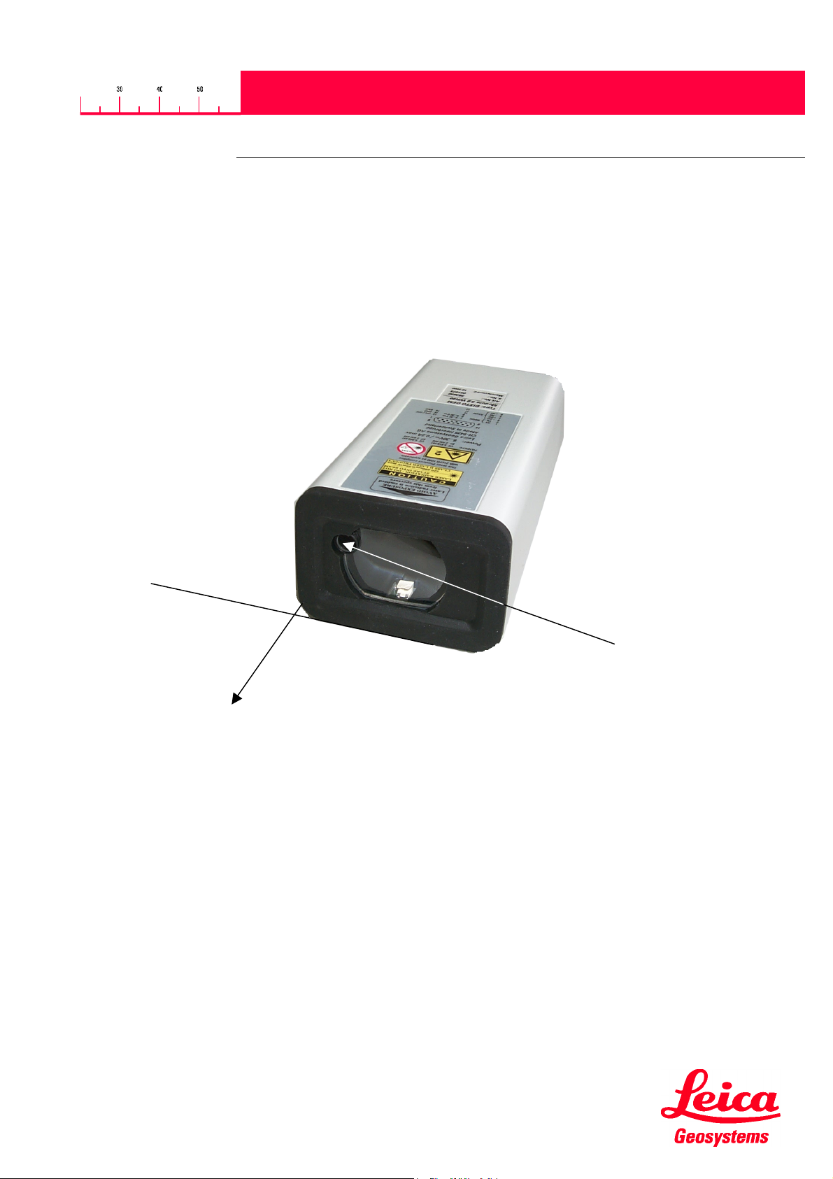
OEM module 3.0 is a powerful, easy to integrate distance measuring module. Due to safety aspects
V1.20
Distance Reference
Type: DISTOTM OEM module 3.0 WH15
Art. No.: 724866
TM
Type: DISTO
Art. No.: 563890
Leica Geosystems AG CH-9435 Heerbrugg
OEM module 3.0 WH30
Laser beam outlet
1/12
725538.doc 08.11.01
Page 2

DISTO
DISTO
DISTODISTO
TM
TM
TMTM
OEM module 3.0 WH15/WH30
OEM module 3.0 WH15/WH30
OEM module 3.0 WH15/WH30 OEM module 3.0 WH15/WH30
Technical Reference Manual
V1.20
Contents:
1. TECHNICAL DATA.............................................................................................................................................................3
2. PHYSICAL DIMENSIONS AND FIXING.............................................................................................................................4
3. INTERFACE PARAMETERS..............................................................................................................................................5
3.1. S
3.2. P
4. POWER ON /OFF ...............................................................................................................................................................6
5. SOFTWARE INTERFACE PROTOCOL.............................................................................................................................6
5.1. G
5.2. D
5.3. W
5.4. E
6. COMMANDS.......................................................................................................................................................................9
6.1. G
6.2. S
7. MEASURING ACCURACY...............................................................................................................................................11
OFTWARE PARAMETERS
IN ASSIGNMENT OF THE D-SUB CONNECTOR
ENERAL DEFINITIONS
5.1.1. Characters .............................................................................................................................................................6
5.1.2. Entries....................................................................................................................................................................6
5.1.3. Replies ...................................................................................................................................................................6
ATA FORMAT
ORD INDEXES
RROR REPORTS
ENERAL
ET OF COMMANDS
6.2.1. RESET command (a).............................................................................................................................................9
6.2.2. OFF command (b)..................................................................................................................................................9
6.2.3. STOP/CLEAR command (c) ..................................................................................................................................9
6.2.4. Distance measurement (g).....................................................................................................................................9
6.2.5. Distance measurement (G)....................................................................................................................................9
6.2.6. Tracking (h)............................................................................................................................................................9
6.2.7. Tracking (H) .........................................................................................................................................................10
6.2.8. Signal measurement (k)....................................................................................................................................... 10
6.2.9. Temperature measurement (t) .............................................................................................................................10
6.2.10. Laser (o, p) .....................................................................................................................................................10
6.2.11. Software version (00) ......................................................................................................................................10
6.2.12. Hardware version (01) .....................................................................................................................................10
6.2.13. Serial number (02)...........................................................................................................................................10
6.2.14. Date of manufacture (03).................................................................................................................................10
6.2.15. Setting distance offset (44)..............................................................................................................................10
6.2.16. Setting baud rate (70)......................................................................................................................................11
...............................................................................................................................................................6
(WI) .....................................................................................................................................................7
...........................................................................................................................................................8
.....................................................................................................................................................................9
...............................................................................................................................................5
...................................................................................................................5
...................................................................................................................................................6
........................................................................................................................................................9
8. ACCESSORIES ................................................................................................................................................................11
9. VALIDITY..........................................................................................................................................................................12
2/12
725538.doc 08.11.01
Page 3

DISTO
DISTO
DISTODISTO
TM
TM
TMTM
OEM module 3.0 WH15/WH30
OEM module 3.0 WH15/WH30
OEM module 3.0 WH15/WH30 OEM module 3.0 WH15/WH30
Technical Reference Manual
1. Technical data
Typical measuring accuracy for WH15 1)
Typical measuring accuracy for WH30
Maximum measuring accuracy for WH15 1)
Maximum measuring accuracy for WH30
Smallest unit displayed 0.1 mm
Measuring range on natural surfaces 0.3 to 30 m
Measuring range on brown (reflecting) target plate ca. 20 to 100 m
Unambiguous display 0 to 300 m
Measuring reference from front edge (See 2 Physical dimensions
Diameter of laser spot at target at a distance of: 10 m Î 6 mm
Time for a measurement: Single measurement
Tracking
Vibration 10 to 50 Hz, +/- 0.15 mm, 5 cycles
Bump (Shock) 25 g, 6 ms,
Light source Laserdiode 620-690 nm (red)
ESD (Without cables) (IEC 61000-4-2 (1995-01) Level 1)
EMC (Without cables) IEC 61000-4-3 (1995-02)
Power supply DC 9V … 30V
Dimensions 140 x 70 x 55 mm
Temperature range Operation
Degree of Protection IP65; IEC60529 (protected against ingress
Interface Serial asynchronous interface
1
) See 7 Measuring accuracy on page 11
2
) In case of permanent measurement (tracking mode) the max. temperature is reduced to 45°C
1
)
1
)
and fixing on page 4)
100 mÎ 60 mm
1 octave / min (at maximum and minimum
operating temperature)
4000 shocks each axis and direction
Drop 500g single shock once, on all surfaces
IEC 60825-1:1993; Class 2
FDA 21CFR Ch.Ι §1040: 1988; Class ΙΙ
Beam divergence:0.16 x 0.6 mrad
Pulse duration: 15x10
Maximum radiant power: 0.95 mW
Maximum radiant power per pulse: 8mW
Measurement uncertainty: ±5%
2kV tested on metal body
EN55022 Klasse B 1994
FCC Part 15 Class B
ON
OFF
-10 °C to +50 °C 2)
Storage
Weight 430 g
-40 °C to +70 °C
of dust and water
(RS232 and RS422)
+/- 1.5 mm
+/- 3 mm
+/- 2 mm
+/- 5 mm
50 mÎ 30 mm
0.6 to ca. 5 sec
0.15 to 5sec
ISO 9022-36-05
ISO 9022-31-06
-9
max. 250mA
27mA @ 10V
V1.20
s
3/12
725538.doc 08.11.01
Page 4
DISTO
DISTO
DISTODISTO
TM
TM
TMTM
OEM module 3.0 WH15/WH30
OEM module 3.0 WH15/WH30
OEM module 3.0 WH15/WH30 OEM module 3.0 WH15/WH30
Technical Reference Manual
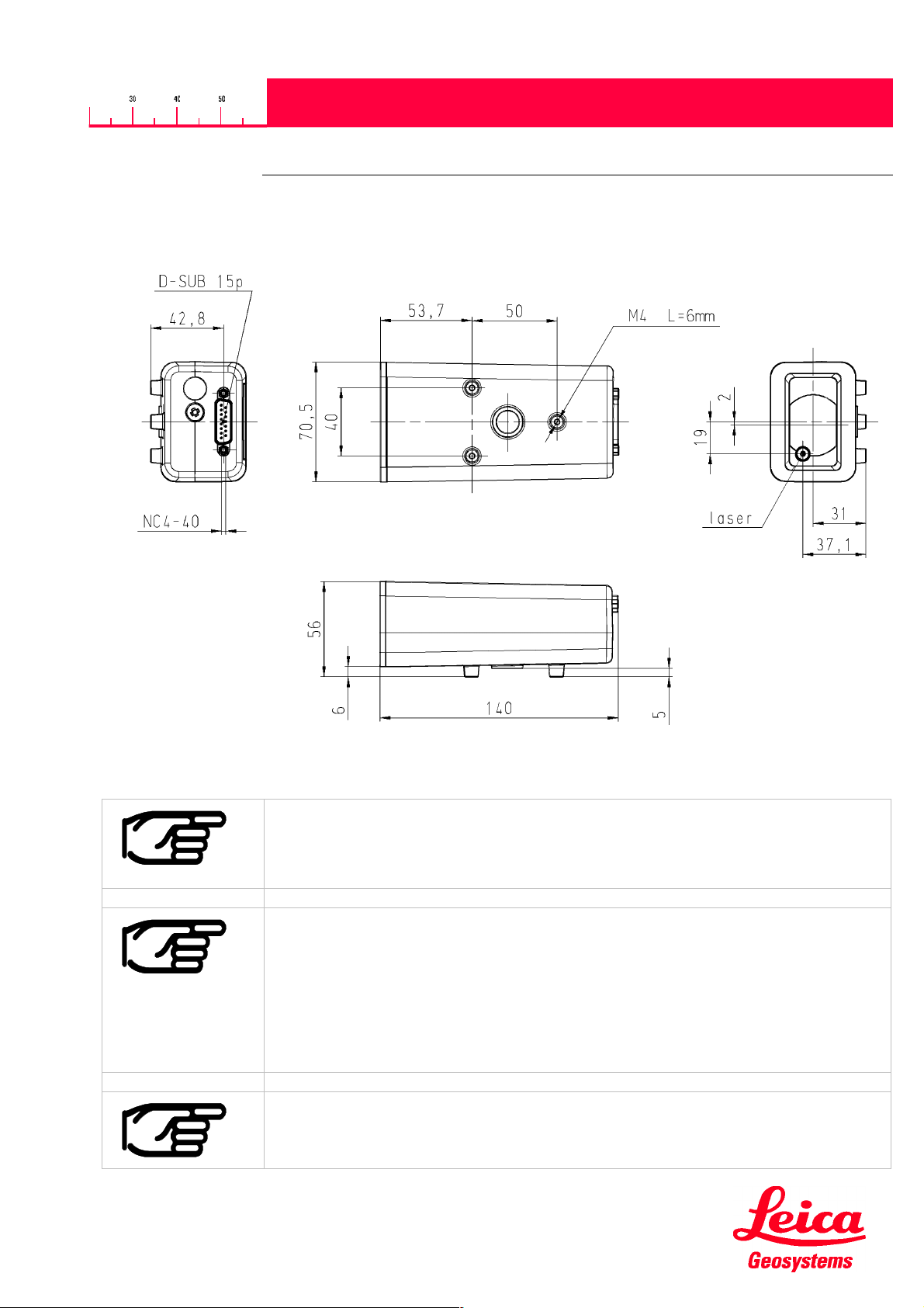
2. Physical dimensions and fixing
V1.20
When fixing the Module you have to be careful not to point the instrument directly toward
the sun. The telescope functions as a magnifying lens and such exposure can damage
the distance measuring device.
You have to ensure, that the optics are kept free from dust, dirt and water.
Clean and Dry:
• Blow away dust from lenses.
• Do not touch the optics with fingers.
• Only clean with a soft cloth; if necessary, dampen with pure alcohol. Do not use other
cleaning agents. Plastic parts could be affected.
Please note the laser beam is not parallel to the housing or to the fixing points.
4/12
725538.doc 08.11.01
Page 5

DISTO
DISTO
DISTODISTO
TM
TM
TMTM
OEM module 3.0 WH15/WH30
OEM module 3.0 WH15/WH30
OEM module 3.0 WH15/WH30 OEM module 3.0 WH15/WH30
Technical Reference Manual
V1.20
3. Interface parameters
3.1. Software parameters
The interface of the DISTOTM OEM module 3.0 has been arranged so that it can be connected to a PC by means
of an adapter. The parameters of the interface are defined ex-works as follows:
9600 baud, none parity, 8 data bits, 1 stop bit
These settings can be changed, using the interface commands.
3.2. Pin assignment of the D-sub connector
The 15 pin D-sub connector contains the lines for RS232, RS422 and the power.
1
VCC
2
3
4
5
6
7
8
9
10
11
12
13
14
15
RX
TX
-DO
+DO
-RI
+RI
9..30VDC
RS232
RS422
ON/OFF
GND
Pin Designator Description Colors for accessories cable
725005 (RS422) 725006 (RS232)
1 RS232 Tx RS232 Send line White
2 RS232 Rx RS232 Receive line Brown
3 -DO RS422 Send line negative W hite
4 +DO RS422 Send line positive Brown
5 -RO RS422 Receive line negative Green
6 +RO RS422 Receive line positive Yellow
7 BAT + Power DC +9V…+30V Brown (Supply cable)
8 BAT + Power DC +9V…+30V
9NC
10 NC
11 NC
12 NC
13 ON / OFF ON: Open OFF: switch to ground Green (Supply cable)
14 GND Ground line Grey Green
15 GND Ground line White (Supply cable)
5/12
725538.doc 08.11.01
Page 6

DISTO
DISTO
DISTODISTO
TM
TM
TMTM
OEM module 3.0 WH15/WH30
OEM module 3.0 WH15/WH30
OEM module 3.0 WH15/WH30 OEM module 3.0 WH15/WH30
Technical Reference Manual
V1.20
4. Power on /off
Pin 13 of the D-sub Connector is Open (Tristate):
•
To switch the module on, use command “a” (See 6.2.1 RESET command (a) on page 9).
To switch the module off, use the command “b” (See 6.2.2 OFF command (b) on page 9). After this
command, the measurement module is switched off, but the electronic interface is still active and waits for the
next command on the serial interface.
Pin 13 of the D-sub Connector is switched to ground:
•
The module and the interface board are switched off. All commands are ignored.
5. Software interface protocol
5.1. General definitions
5.1.1. Characters
All characters with ASCII codes below 127 can be used for entering commands. A command is concluded by
means of an ASCII code below 32 (last character or terminator <trm>).
The
DISTO
<cr><lf>.
TM
OEM module 3.0
also transmits a terminator to conclude a reply. The terminator transmitted is
5.1.2. Entries
Each
DISTO OEM module 02
Examples:
Numerical entries (command parameters, %) are always entered as whole numbers and the following format is
permitted:
5.1.3. Replies
DISTOTM OEM module 3.0
replies:
?<trm>
@E123<trm>
12..10+12345678 <trm>
Plain text
A command will result in at least an OK prompt or an error report.
a<trm>
N00N<trm>
Sign (optional) and digits which do not commence with zero: -8007.
command consists of one or more letters and a terminator.
transmits one or more replies to each command received. These are the possible
- OK prompt: Everything ok,
a new command
- Error report: A three-digit error code is transmitted in accordance with the
table in the appendix.
- One or more data words with terminator.
- Plain-text data
DISTO
TM
OEM module 3.0
is ready to execute
5.2. Data format
A data word as reply consists of 16 characters, combined as follows:
6/12
725538.doc 08.11.01
Page 7

DISTO
DISTO
DISTODISTO
TM
TM
TMTM
OEM module 3.0 WH15/WH30
OEM module 3.0 WH15/WH30
OEM module 3.0 WH15/WH30 OEM module 3.0 WH15/WH30
Technical Reference Manual
12345678910111213141516
WW....+12345678
Position Description: Remark
1,2 Word index 00-99 With zeroes at start
3,4 no significance In service mode as expansion of word index
5 Attribute 0: Measured value
1: Manually-entered value
6 Units 0: mm
. : No units
7-15 Decimal value With sign and zeroes at start
16 Space
In some instances the following data format appears:
12345678910111213141516
WW....+1234+678
Position Description: Remark
1,2 Word index 00-99 With zeroes at start
3,4 no significance In service mode as expansion of word index
5 Attribute 0: Measured value
1: Manually-entered value
. : No attribute set
6 Units 0: mm
. : No units
7-11 Decimal value 1 With sign and zeroes at start
12-15 Decimal value 2 With sign and zeroes at start
16 Space
V1.20
5.3. Word indexes (WI)
The following WIs are available to the user:
WI no. Format (example) Meaning Rem.
12
13
14
15
31
40
51
53
58
12....+xxxxxxxx
13....+xxxxyyyy
14....+xxxxxxyy
15....+xxxxxxxx
31..06+xxxxxxxx
40....+xxxxxxxx
51....+xxxxxxxx
53....+xxxxxxxx
58..16+xxxxxxxx
7/12
725538.doc 08.11.01
Serial number of module
[0....99999999]
Software version
xxxx: Identification
yyyy: SW-Version 0100 -> V1.00
Hardware version
xxxxxx: Board number
yy: Revision index
Date of manufacture [YYYYMMDD] Year, Month, Day
Slope distance [1/10 mm]
Temperature [1/10 º C]
Always 0 (only for compatibility reasons)
Measurement signal [mV]
Distance offset [1/10 mm]
Page 8

DISTO
DISTO
DISTODISTO
TM
TM
TMTM
OEM module 3.0 WH15/WH30
OEM module 3.0 WH15/WH30
OEM module 3.0 WH15/WH30 OEM module 3.0 WH15/WH30
Technical Reference Manual
5.4. Error reports
No. Format Meaning
203
217
221
222
223
224
252
@E203
@E217
@E221
@E222
@E223
@E224
@E252
Prohibited parameter in command entry, or prohibited command, or non-valid
result
Parameter set-up incorrect (Contact Leica Geosystems)
Parity error (Prior to contacting Leica Geosystems please check the Terminal
settings)
Interface buffer overflow
(Contact Leica Geosystems if error occurs when sending less than 24
characters)
Interface framing error
(Contact Leica Geosystems)
GSI buffer overflow
(Contact Leica Geosystems if error occurs when sending less than 24
characters)
Temperature too high
(contact Leica Geosystems if error occurs at room temperature)
V1.20
253
255
256
257
272
to
299
Before contacting Leica Geosystems please collect as much information as possible.
@E253
@E255
@E256
@E257
@E272
Temperature too low
(contact Leica Geosystems if error occurs at room temperature)
Received signal too weak, distance < 250mm
(Use different target and distances, if the problem persists, please contact Leica
Geosystems)
Received signal too strong
(Use different target and distances, if the problem persists, please contact Leica
Geosystems)
Too much background light
(Use different target and distances, if the problem persists, please contact Leica
Geosystems)
Hardware failure (Contact Leica Geosystems)
8/12
725538.doc 08.11.01
Page 9

DISTO
DISTO
DISTODISTO
TM
TM
TMTM
OEM module 3.0 WH15/WH30
OEM module 3.0 WH15/WH30
OEM module 3.0 WH15/WH30 OEM module 3.0 WH15/WH30
Technical Reference Manual
V1.20
6. Commands
6.1. General
After a command has been entered, it is decoded and processed. If additional commands are sent, processing of
the current command will be aborted if possible and the last command to be received will be processed. After the
command has been executed, there will always be either an OK prompt or an error report.
6.2. Set of commands
6.2.1. RESET command (a)
Function: Resets the module.
GSI IN: a<trm>
GSI OUT: ?<trm> or @Exxx<trm>
6.2.2. OFF command (b)
Function: Switches the module off. It is very important to switch the module off, before disconnecting the
power. To switch the module on, use pin 2 at connector J1
(See 3.2 Pin assignment on page 5).
GSI IN: b<trm>
GSI OUT: ?<trm> or @Exxx<trm>
6.2.3. STOP/CLEAR command (c)
Function: Stops the current execution.
GSI IN: c<trm>
GSI OUT: ?<trm> or @Exxx<trm>
6.2.4. Distance measurement (g)
Function: Triggers simple measurement of distance. Each new command cancels an active
measurement.
GSI IN: g<trm>
GSI OUT: WI31 WI51<trm> or @Exxx<trm>
6.2.5. Distance measurement (G)
Function: Triggers configurable measurement of distance.
(not implemented in the current SW version, react like the command g)
GSI IN: G<trm>
GSI OUT: WI31<trm> or @Exxx<trm>
6.2.6. Tracking (h)
Function: Triggers continuous measurement of distance. The measurements are continued until the next
command is issued or until a fault arises.
GSI IN: h<trm>
GSI OUT: WI31 WI51<trm> or @Exxx<trm>
9/12
725538.doc 08.11.01
Page 10

DISTO
DISTO
DISTODISTO
TM
TM
TMTM
OEM module 3.0 WH15/WH30
OEM module 3.0 WH15/WH30
OEM module 3.0 WH15/WH30 OEM module 3.0 WH15/WH30
Technical Reference Manual
6.2.7. Tracking (H)
Function: Triggers continuous measurement of distance. The measurements are continued until the next
command is issued or until a fault arises.
GSI IN: H<trm>
GSI OUT: WI31<trm> or @Exxx<trm>
6.2.8. Signal measurement (k)
Function: Triggers continuous measurement of the signal. The measurements are continued until the
next command is received or until a fault arises.
GSI IN: k<trm>
GSI OUT: WI53<trm> or @Exxx<trm>
6.2.9. Temperature measurement (t)
Function: : Triggers measurement of temperature.
GSI IN: t<trm>
GSI OUT: WI40<trm> or @Exxx<trm>
6.2.10. Laser (o, p)
Function: Switches laser on or off.
GSI IN: o<trm> Switches laser on
p<trm> Switches laser off
GSI OUT: ?<trm> or @Exxx<trm>
V1.20
6.2.11. Software version (00)
Function: Outputs software version at interface.
GSI IN: N00N<trm>
GSI OUT: WI13<trm> or @Exxx<trm>
6.2.12. Hardware version (01)
Function: Outputs instrument type at interface.
GSI IN: N01N<trm>
GSI OUT: WI14<trm> or @Exxx<trm>
6.2.13. Serial number (02)
Function: Outputs serial number at interface.
GSI IN: N02N<trm>
GSI OUT: WI12<trm> or @Exxx<trm>
6.2.14. Date of manufacture (03)
Function: Date of manufacture at interface.
GSI IN: N03N<trm>
GSI OUT: WI15<trm> or @Exxx<trm>
6.2.15. Setting distance offset (44)
Function: Sets distance offset. The offset is added to each distance measured. Setting is nonvolatile!
GSI IN: N44N%N<trm>
%: Distance offset [1/10mm] within the range ±29.999m
GSI OUT: WI58<trm> or @Exxx<trm>
10/12
725538.doc 08.11.01
Page 11

DISTO
DISTO
DISTODISTO
TM
TM
TMTM
OEM module 3.0 WH15/WH30
OEM module 3.0 WH15/WH30
OEM module 3.0 WH15/WH30 OEM module 3.0 WH15/WH30
Technical Reference Manual
6.2.16. Setting baud rate (70)
Function: Sets the baud rate with fixed parity (none parity).
GSI IN: N70N%N<trm>
% Baud rate % Baud rate
3 1200 6 9600
4 2400 7 19200
5 4800
GSI OUT: ?<trm> or @Exxx<trm>
7. Measuring accuracy
The measuring accuracy corresponds to the ISO-recommendation ISO/R 19381971 with a statistical confidence level of 95% (i.e. ± twice the standard deviation,
refer to diagram below). The typical measuring accuracy relates to average
conditions for measuring. It is valid in the tracking mode.
The maximum measuring error relates to unfavorable conditions such as:
- highly-reflecting surfaces (e.g. reflector tapes)
- operating at the limits of the permitted temperature range, adaptation to ambient
temperature interrupted
- very bright ambient conditions, strong heat shimmer
and can be up to ± 2 mm for WH15 and ± 5 mm for W H30 (twice standard
deviation).
V1.20
99.7%
95.4%
68.27%
-2s 2s
-3s
During the measuring time the distance will be averaged. This applies when measuring to
moving targets.
x
-s s 3s
8. Accessories
Interface Cable (725706)
IP65 protected cable for RS232 Interface and power supply (15 pin D-sub to 9 pin D-sub female connector and
separate Power Supply). For colors and assignment refer to table under 3.2 Pin assignment of the D-sub
connector.
Length 3m
Interface Cable (725705)
IP65 protected cable for RS422 Interface and power supply (15 pin D-sub to RS422 and separate Power Supply).
For colors and assignment refer to table under 3.2 Pin assignment of the D-sub connector.
Length 3m
Software (Disto Online)
Is continuously updated. Ask your module dealer or visit the DISTO web site at http://www.disto.com
11/12
725538.doc 08.11.01
Page 12

DISTO
DISTO
DISTODISTO
TM
TM
TMTM
OEM module 3.0 WH15/WH30
OEM module 3.0 WH15/WH30
OEM module 3.0 WH15/WH30 OEM module 3.0 WH15/WH30
Technical Reference Manual
V1.20
9. Validity
This document is valid for the DISTOTM OEM module 3.0. The following firmware versions support the listed
commands:
To get this information refer to
Identification: 0000
Version: V2.00
Version: V2.20
Version: V3.20
6.2.11 Software version (00)
(0000)
(0200)
(0220)
(0320)
on Page 10.
725538-1.2.0en
Printed in Switzerland
Copyright Leica Geosystems AG, Heerbrugg, Switzerland 2001
12/12
725538.doc 08.11.01
Leica Geosystems AG
DISTO
CH-9435 Heerbrugg
(Switzerland)
Phone ++41 71 727 31 31
Fax ++41 71 727 46 73
www.leica-geosystems.com
 Loading...