

Page 1
Version 1.0
English
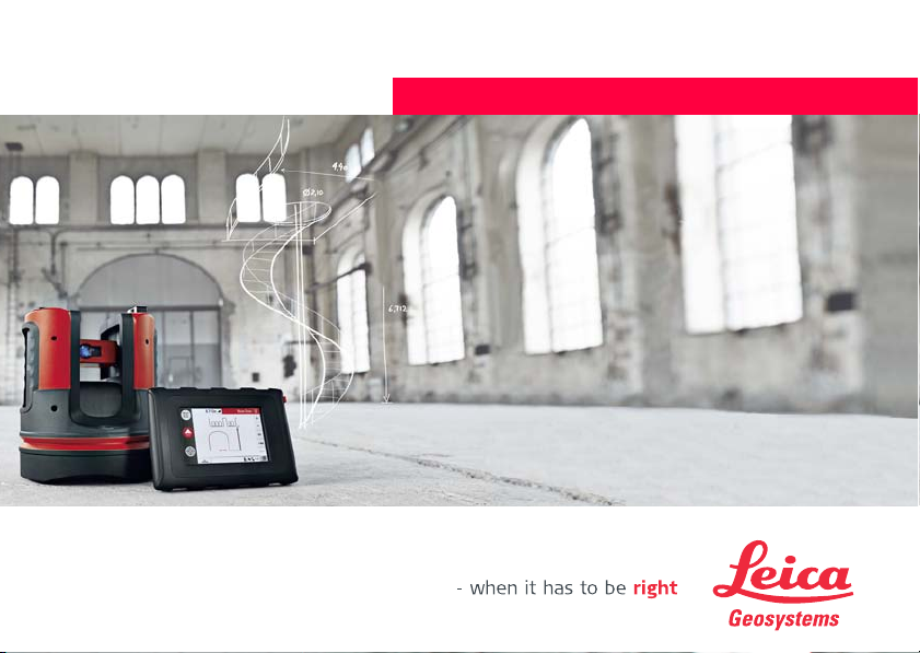
Leica 3D Disto
User Manual
Page 2
3D Disto, Introduction
Introduction
Purchase Congratulations on the purchase of a Leica 3D Disto.
This manual contains important safety directions as well as instructions for setting
up the product and operating it. Refer to "12 Safety Directions" for further information.
Read through the User Manual carefully before you switch on the product.
2
Product
identification
The serial number of your product is indicated on the data label, refer to "12.8 FCC
Statement, Applicable in U.S.". Enter the serial number in your manual and always
refer to this information when you need to contact your authorised dealer or to
register in the Leica MyWorld portal.
Serial No.: _______________
Page 3

Symbols The symbols used in this manual have the following meanings:
Type Description
Danger Indicates an imminently hazardous situation which, if not
Warning Indicates a potentially hazardous situation or an unintended
Caution Indicates a potentially hazardous situation or an unintended
Trademarks • Windows is a registered trademark of Microsoft Corporation.
All other trademarks are the property of their respective owners.
3D Disto, Introduction 3
avoided, will result in death or serious injury.
use which, if not avoided, could result in death or serious
injury.
use which, if not avoided, may result in minor or moderate
injury and/or appreciable material, financial and environmental damage.
Important paragraphs which must be adhered to in practice
as they enable the product to be used in a technically
correct and efficient manner.
Page 4

3D Disto, Table of Contents
Table of Contents
In this manual Chapter Page
1 How to Use this Manual 9
2 Technical Terms and Abbreviations 13
3 Description of the System 26
3.1 General 3D Disto System Information 26
3.2 Container Contents 27
3.3 Instrument Components 29
3.3.1 3D Disto 29
3.3.2 Control Unit 33
3.3.3 RM100 Remote Control 34
3.4 Power Supply 35
3.4.1 3D Disto 35
3.4.2 Control Unit 36
3.4.3 RM100 Remote Control 38
3.5 Software Concept 39
4
Page 5

4 User Interface 45
4.1 Control Unit 45
4.1.1 Screen 46
4.1.2 Main Operation Bar 49
4.1.3 Toolbar 50
4.1.4 Icons & Symbols 51
4.2 RM100 Remote Control 55
5 Instrument Setup 56
5.1 Start-up Procedure 56
5.2 Assistant 64
5.3 Device Configuration and Menu Settings 66
5.4 Data Management 69
5.4.1 General 69
5.4.2 File Manager 71
5.4.3 Photo and Secure Points Administration 72
5.4.4 Data Transfer 74
5.5 Calculator 80
3D Disto, Table of Contents 5
Page 6

3D Disto, Table of Contents
6 Operation 82
6.1 Measurements 82
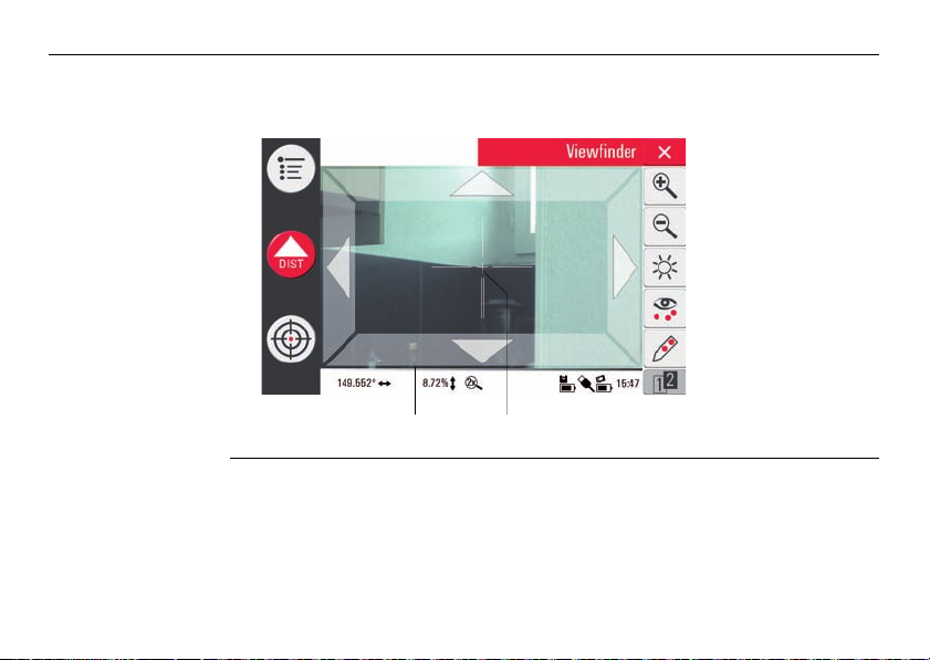
6.2 Viewfinder 83
6.3 Measurement Workflow 87
6.4 Touch Screen in Sketch Area 93
6.5 Addition and Subtraction 95
6.6 Area & Volume Calculations 98
7 Software Applications 102
7.1 Overview 102
7.2 Tool Kit 103
7.3 Location 116
6
6.6.1 Horizontal Areas/Volumes 99
6.6.2 Tilted Areas 101
7.2.1 Comfort Plumbing 104
7.2.2 Comfort Targeting 106
7.2.3 Comfort Level 108
7.2.4 Metre Mark 110
7.2.5 Height Tracking 112
7.2.6 Parallel Line 114
Page 7

7.4 Room Scan 122
7.4.1 Manual Measurement 124
7.4.2 Unfold Mode 126
7.4.3 Auto Shapes 128
7.4.4 Automated Profile Room Scan 131
7.5 Projector 137
7.5.1 Workflow 138
7.5.2 Targeting and Layout with RM100 Remote Control 145
8 Error Messages 146
9 Check & Adjust 149
9.1 Overview 149
9.2 Crosshairs Offset 151
9.3 V-Index Error 153
9.4 Tilt Sensor Calibration 155
9.5 Reset to Factory Settings 157
10 Instrument Protection (Theft Protection) 158
11 Care and Transport 160
11.1 Transport 160
11.2 Storage 161
11.3 Cleaning and Drying 162
3D Disto, Table of Contents 7
Page 8

3D Disto, Table of Contents
12 Safety Directions 163
12.1 General 163
12.2 Intended Use 164
12.3 Limits of Use 166
12.4 Responsibilities 167
12.5 Hazards of Use 168
12.6 Laser Classification 172
12.7 Electromagnetic Compatibility EMC 174
12.8 FCC Statement, Applicable in U.S. 177
12.9 Conformity to National Regulations 181
13 Technical Data 182
14 International Limited Warranty, Software License Agreement 187
Index 190
8
Page 9
1 How to Use this Manual
Index The index is at the back of the manual.
Validity of this
manual
Available
documentation
3D Disto, How to Use this Manual
It is recommended to set up the instrument while reading through this manual.
Keys, fields and options on the screens which are considered self-explanatory are not
explained.
This manual applies to the 3D Disto instruments and software application.
Name Description/Format
3D Disto User
Manual
3D Disto Quick
Start
Safety Manual Provides important safety instructions for use of
All instructions required in order to operate the
instrument at a basic level are contained in this User
Manual. Provides an overview of the instrument
together with technical data and safety directions.
Intended as a quick reference field guide.
3D Disto.
-
9
Page 10

3D Disto, How to Use this Manual
Refer to the following resources for all 3D Disto documentation/software:
• Leica 3D Disto CD
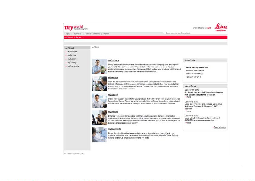
• https://myworld.leica-geosystems.com
myWorld@Leica Geosystems (https://myworld.leica-geosystems.com) offers a wide
range of services, information and training material.
In myWorld, you are able to access all relevant services at your convenience, 24 hours
a day, 7 days a week. This increases your efficiency and keeps you and your equipment updated with the latest information from Leica Geosystems.
10
Page 11
3D Disto, How to Use this Manual
11
Page 12
3D Disto, How to Use this Manual
Service Description
myProducts Simply add all Leica Geosystems products that you and your
mySupport Create new support requests for your products that will be
myTraining Enhance your product knowledge with the Leica Geosystems
12
company own. View detailed information on your products, buy
additional options, update your products with the latest software
and keep up-to-date with the latest documentation.
answered by your local Leica Geosystems Support Team. See the
complete history of your support cases and view detailed information on each request if you want to refer to previous support
requests.
Campus - Information, Knowledge, Training. Study the latest online
training material or download training material on your products.
Keep up-to-date with the latest news on your products and register
for seminars or courses in your country.
Page 13
2 Technical Terms and Abbreviations
3D Disto_013
a
b
c
a
3D Disto_015
Line of sight
Horizontal angle
3D Disto, Technical Terms and Abbreviations
a) Line of sight
b) Tilting axis, horizontal rotation axis of the
instrument
c) Standing axis, vertical rotation axis of the
instrument
a) Horizontal angle: [°] or [gon]
Line of sight, laser beam and crosshairs
must be congruent. Refer to "9 Check &
Adjust" for more information.
13
Page 14
3D Disto, Technical Terms and Abbreviations
3D Disto_016
a
3D Disto_017
a
Vertical angle
14
Setting: Horizon = 0
a) Vertical angle: [°], [gon], [1:n] or [%]
Setting: Horizon = 90°/100gon
a) Vertical angle: [°] or [gon]
Page 15
Distances
a
3D Disto_018
3D Disto_019
a) Perpendicular distance
a
b
c
a) Tie distance
b) Vertical distance = height difference
c) Horizontal distance
3D Disto, Technical Terms and Abbreviations
15
Page 16
3D Disto, Technical Terms and Abbreviations
3D Disto_014
a
b
Areas
a
b
3D Disto_020
Zenith and horizon
16
a) Tilted area, as measured
b) Horizontal area, calculated by 3D Disto
a) Zenith:
Point on the plumb line above the observer.
b) Horizon:
Plane/Line 90° to the plumb line.
Page 17
References
3D Disto_022
4.160
5.390
3.965
5.134
1.884
a
+3.00
+2.10
0.00
-0.02
3D Disto_021
3D Disto, Technical Terms and Abbreviations
0.00
a
0.00
a) Reference height:
A level that all heights refer to.
a) Reference point:
A point that all dimensions refer to.
17
Page 18
3D Disto, Technical Terms and Abbreviations
3D Disto_023
3.101
2.911
7.040
7.002
a
18
a) Reference axis/line:
A line that all dimensions refer to.
Page 19
Tilt sensor The tilt sensor guarantees correct results even if the 3D Disto is not set up horizon-
3D Disto_024
3D Disto_025
0-3°
tally.
Tilt sensor off = disabled
All measurement results relate to the
tilted axis and horizon of the 3D Disto.
3D Disto, Technical Terms and Abbreviations
Tilt sensor on = enabled
All measurement results relate to the
horizontal axis and horizon if the
3D Disto is set up between 0° and 3°.
19
Page 20
3D Disto, Technical Terms and Abbreviations
S_3D Disto_002 a b
Viewfinder and
crosshairs
• Viewfinder is an integrated camera which shows the target on the Control Unit
display.
• Crosshairs is an aiming guide displayed on the Control Unit.
20
a) Viewfinder
b) Crosshairs
Page 21
Secure Points Secure Points links measurements to a coordinate system. These reference
3D Disto_026
points allow changing the 3D Disto’s location or continuing measurements at a later
time, so that all measurements fit together perfectly.
1. Name and place three to five self-adhesive
target marks on walls, ceiling or floor around
your working area.
2. Measure these target marks and save them as
Secure Points.
3. Move the 3D Disto or set it up "anywhere" at
a later time.
4. Measure the Secure Points again. 3D Disto
relocates itself and measurements can be
continued.
3D Disto_027
Refer to "7.3 Location" for more information.
3D Disto, Technical Terms and Abbreviations
21
Page 22
3D Disto, Technical Terms and Abbreviations
Coordinates Coordinates describe the position of a point in two- and three-dimensional space.
b
a
22
3D Disto_028
m/ft
a) Two-dimensional coordinates
b) Three-dimensional coordinates
Page 23
Measure Measurement results can be transferred to a connected PC or USB stick for post-
3D Disto_045
CAD
processing.
3D Disto, Technical Terms and Abbreviations
23
Page 24
3D Disto, Technical Terms and Abbreviations
Layout or
projection
Design data in DXF format can be imported and used to lay out the corresponding
points or grids.
CAD
3D Disto_046
24
Laser distance
metre (LDM)
Calibration Calibration is a workflow to check and adjust the accuracy of the instrument.
The laser distance metre (LDM) determines distances using a visible red laser beam.
Refer to "9 Check & Adjust" for more information.
Page 25
Ruler for offset
points
The ruler for offset points is an accessory to measure inaccessible or hidden points.
3D Disto_035
a) Ruler for offset points
3D Disto, Technical Terms and Abbreviations
?
a
25
Page 26
3D Disto, Description of the System
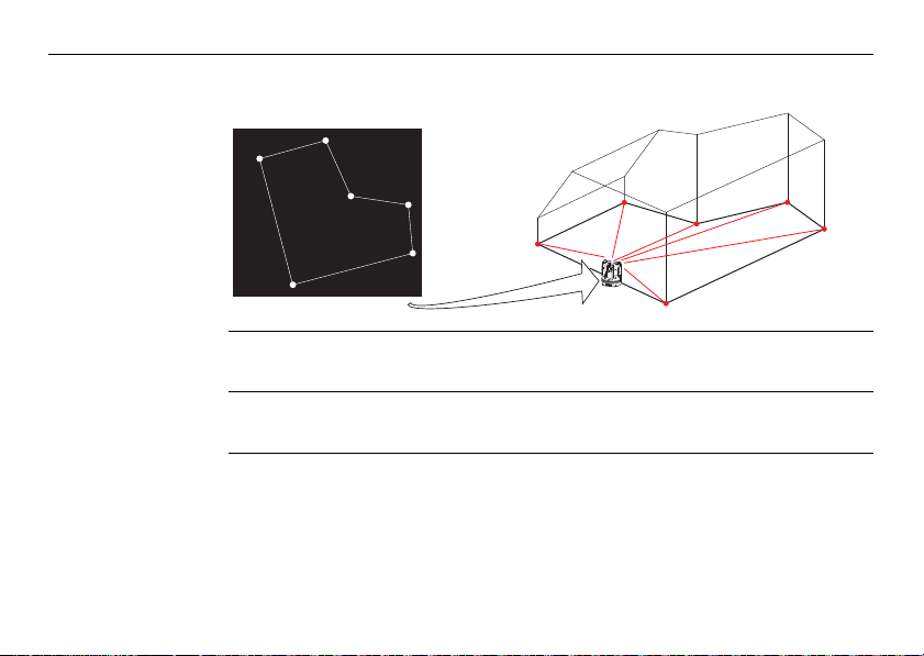
3 Description of the System
3.1 General 3D Disto System Information
26
General
information
Leica Geosystems’ 3D Disto is a three-dimensional measuring and projection system
to measure points in a room from one setup position and that generates 3D data –
ready to use or for post-processing.
a) 3D Disto
b) USB cable
c) Control Unit
d) RM100 Remote
3D Disto_001 a b c d
3D Disto is operated by the Control Unit. Certain functions can also be executed using
the RM100 Remote Control.
Control
Page 27
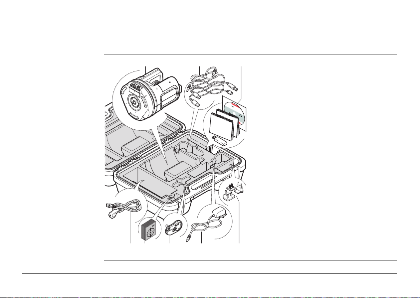
3.2 Container Contents
ab
e
f g hd
c
3D Disto_002
Container
contents,
part 1 of 2
a) 3D Disto with built-in SD WLAN card
b) USB connection cable 3D Disto to the
Control Unit
Power cable 3D Disto to the Control
Unit
Micro-USB cable for PC
c) Data CD
Safety Instructions Manual,
3D Disto Quick Start,
CE & Producer Certificate,
USB Stick
d) Four country-specific cables for
3D Disto power supply
e) Target marks, self-adhesive, 50 units
in one bag
f) RM100 Remote Control
g) Control Unit power supply
h) Country-specific adapter plug-ins for
Control Unit power supply
3D Disto, Description of the System
27
Page 28
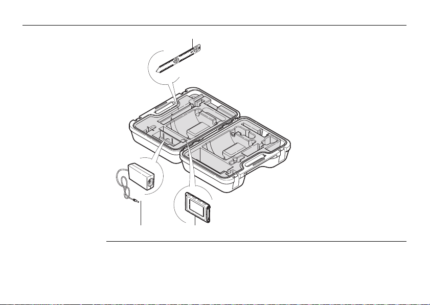
3D Disto, Description of the System
i
j
3D Disto_003
k
Container
contents,
part 2 of 2
28
i) Ruler for offset points
j) 3D Disto power supply
k) Control Unit with stylus,
tripod clamp and hand
strap
Page 29
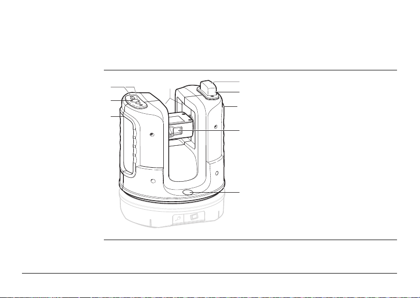
3.3 Instrument Components
3.3.1 3D Disto
Instrument
components,
motor-driven part
a
b
c
3D Disto_004
3D Disto, Description of the System
c
d
e
c
f
a) LEDs for 3D Disto status
b) ON/OFF button
c) Grips to hold the instrument
g
d) Infrared (IR) interface
e) WLAN interface
f) Laser distance metre with Viewfinder
g) Circular bubble
29
Page 30
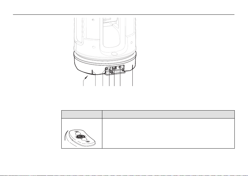
3D Disto, Description of the System
3D Disto_005
dc e f bba
Instrument
component,
battery socket
Description of buttons and LEDs
Button/LEDs Description
ON/OFF button Button to turn instrument ON or OFF.
30
a) Tripod thread 5/8”
b) 90° marking
c) Power supply connector for 3D Disto
d) LED for battery status
e) Data cable connector
f) Power supply connector to Control
Unit
Instrument turns OFF after 15 minutes if not connected to the
Control Unit.
Page 31

Button/LEDs Description
LEDs for 3D Disto
status
LED for battery
status
• Green and orange LEDs flashing: 3D Disto is turned ON.
• Orange LED flashes fast: Booting and self-levelling procedure is running.
• Green LED flashes slowly: tilt 3° after self-levelling check.
3D Disto is ready for measurement. Tilt sensor is on.
• Orange LED flashes fast: tilt > 3° after self-levelling check.
• Green LED off, orange LED flashes continuously:
An error occurred. Refer to "8 Error Messages" for more
information.
For experts only: Tilt sensor off
• Green LED flashes slowly, followed by orange LED flashing
three times while green LED is off.
If instrument is on and connected to the charger:
• Green LED flashes 1x: Battery is charged to 25 %.
• Green LED flashes 2x: Battery is charged to 50 %.
• Green LED flashes 3x: Battery is charged to 75 %.
• Green LED is on: Battery is fully charged.
3D Disto, Description of the System
31
Page 32

3D Disto, Description of the System
Button/LEDs Description
LDM Laser • OFF: Viewfinder is OFF or 3D Disto targets automatically.
32
• ON: Viewfinder is ON; user is targeting manually.
• Flashing: to indicate the precise position of a projected
point.
Page 33

3.3.2 Control Unit
Control Unit
components
3D Disto_006
3D Disto, Description of the System
a
b
c
d
e
f
a) ON/OFF button
b) Stylus
g
c) Display, 4.8" touch screen
d) Power supply connector
e) USB Port, type A
f) Tripod clamp, extendable
h
g) Hand strap
h) Micro-USB port, type Micro-B
33
Page 34

3D Disto, Description of the System
RM100
acbde
3D Disto_007
3.3.3 RM100 Remote Control
Remote Control
components
34
a) Key ring
b) Battery compartment
c) Dist button
d) Navigation buttons:
Up/down/right/left
e) Control LED
Page 35

3.4 Power Supply
a
3D Disto_008
b
3.4.1 3D Disto
3D Disto power
supply
3D Disto, Description of the System
Power for the instrument can be supplied either internally or externally:
• Internal: by battery socket, with non-removable Li-Ion batteries, 14.4 V, 63 Wh.
• External:
Only Leica Geosystems authorised service workshops are entitled to replace the
battery socket.
Power supply for 3D Disto connected by cable with country-specific plugs for
worldwide use. Input: 100 - 240 V AC, 50/60 Hz. Output: 24 V DC, 2.5 A. Length
1.80 m.
a) Battery socket
b) Power supply connector
35
Page 36

3D Disto, Description of the System
3.4.2 Control Unit
36
Control Unit power
supply
Power for the Control Unit can be supplied either internally or externally:
• Internal: non-removable Lithium polymer battery, 2500 mAh, 3.7 V DC.
• External:
3D Disto_009
• Power supply with AC/DC adapter. EU, US, UK and AUS adapter plug-ins avail-
The display of the Control Unit turns off after 15 minutes to save power
during periods of inactivity.
a
a) Power supply cable from 3D Disto
b) Power supply from mains supply
b
with AC/DC adapter
able. Input: 100 - 240 V AC, 50/60 Hz. Output: 5.2 V DC, 2000 mA. Cable
length 1.50 m.
The Control Unit powers on when plugging in the power supply adapter.
Page 37

• Power supply from 3D Disto by cable: > 5 V, 2.5 A, length 2.00 m.
The Control Unit can only be charged if the 3D Disto is charged more
than 25%.
3D Disto, Description of the System
37
Page 38

3D Disto, Description of the System
3D Disto_010
2
1
3.4.3 RM100 Remote Control
38
RM100 Remote
Control power
supply
The RM100 is equipped with one AA alkaline battery, 1.5 V.
1. Push the battery cover in the direction
of the arrow to open the battery
compartment.
2. Replace the battery and refit the
battery cover.
Page 39

3.5 Software Concept
3D Disto system
software
Application
programs
Demo mode The available application programs can be tested by activating the Demo mode. This
3D Disto, Description of the System
The 3D Disto software includes the central functions of the instrument:
• Several languages are integrated into this software. The preferred operating
language can be chosen during the first setup or in the Setting menu.
• The instrument has a restart function in case the Control Unit is not responding.
To restart the instrument press for ten seconds.
• To reset the software to the factory settings go to Menu, press Settings and
Reset to default.
Several application programs are available for the instrument, supported by assistant
pop-ups that guide through the workflow. These applications can be tested in a
Demo mode or activated with license keys.
provides full software performance for 40 working hours. A pop-up reminds the user
when the Demo mode expires.
To enable the application programs in Demo mode, carry out the following steps:
1. Press Menu » Applications » Demo.
2. All application programs are listed in the Menu and marked with until Demo
mode runs out.
39
Page 40

3D Disto, Description of the System
3D Disto_011
Customised
application
programs
Customised software, specific to user requirements, can be developed using the
third-party software development environment. Further information is available on
request from a Leica Geosystems representative.
40
Software
application
licensing and
activation
The application programs can be activated by starting the Demo mode or by entering
the license key using one of the following methods:
• Synchronisation with the MyWorld homepage on
www.leica-geosystems.com:
1. Press and connect the Control
Unit to the PC by Micro-USB cable.
The Control Unit is available as a
removable drive on your PC.
2. If the Control Unit does not recognise the PC connection automatically,
press .
3. If the connection works, start your internet browser and go to the MyWorld
homepage. Register your product by entering the equipment number that can be
Page 41

found on the label below the laser distance metre. Refer to "Labelling 3D Disto",
page 179.
4. Choose the MyProduct page and press the activation key for licenses.
5. A Windows pop-up prompts you to save the license key file. Save the file in the
Licence folder on your Control Unit.
Variations in 3D Disto Windows Software
1. Install 3D Disto software on your PC.
2. Start your internet browser and go to the MyWorld homepage. Register your
product by entering the equipment number.
3. Choose the MyProduct page and press the activation key for licenses.
4. Save the license key file in the Licence folder in the directory My Documents\Leica Geosystems\3D Disto.
3D Disto, Description of the System
41
Page 42

3D Disto, Description of the System
• Entering the licence key manually:
1. Press and go to Menu » Device » Software » License.
2. Enter the key, which you can get on the MyWorld
webpage, and press OK.
42
Activated application programs are available in the Applications menu.
Page 43

Software update
3D Disto_011
1. Press and connect the Control
Unit to the PC by Micro-USB cable.
2. If the Control Unit does not recognise the PC connection automatically
3. If the connection works, start the internet browser and go to the MyWorld
4. Go to the MyProduct page, choose the latest software version and press the
5. A standard Windows pop-up prompts you to open or save the file. Save the file
6. Disconnect the Control Unit from the PC and start the installation in Menu »
3D Disto, Description of the System
Ensure the Control Unit battery is fully charged before starting the software
update to avoid data loss. Do not disconnect from PC before download has
finished. Please save and export your measurement data before starting
the software update.
press .
homepage. Register your product by entering the equipment number.
Save key.
in the Update folder on your Control Unit.
Device » Software » Update.
43
Page 44

3D Disto, Description of the System
Variations in 3D Disto Windows Software
1. Start your internet browser and go to the MyWorld homepage. Register your
product by entering the equipment number.
2. Choose the MyProduct page, choose the latest software version and press the
Save key.
3. Save the file in the Update folder in the directory My Documents\Leica
Geosystems\3D Disto.
44
Page 45

4 User Interface
4.1 Control Unit
User input The 4.8" touch screen display is the main control device for the 3D Disto.
3D Disto, User Interface
It is used to navigate within the different applications and menus as well to control
the 3D Disto.
Certain functions can also be executed using the RM100 Remote Control.
Leica Geosystems recommends using the supplied stylus on the touch screen.
45
Page 46

3D Disto, User Interface
S_3D Disto_001
b
a
c
d
e
g
f
4.1.1 Screen
46
Screen
All shown screens are examples. It is possible that local software versions vary from
the standard version.
a) Results window with result
choice key
b) Title bar
c) Toolbar
d) 3D Disto position
e) Sketch area/Viewfinder
f) Status bar
g) Main operation bar
Page 47

Description
Element Description
Title bar Shows the open application.
save and close files or running applications.
shut down the Control Unit.
Main operation
bar
Sketch area, alternating with Viewfinder
Viewfinder, alternating with sketch
area
Results window Displays all results such as distances, heights, slopes, areas,
Contains the keys Menu , Dist , and
Viewfinder .
These keys are displayed during all applications.
Displays measured points, lines and areas and correct position
of 3D Disto in relation to measured points - either in foot print
or face mode.
Shows 3D Disto’s live video stream used to target points over
longer distances, up to 50 m, exactly and to take pictures.
angles together with the corresponding result choice key, for
example . Use this key to switch between the result types.
Tapping on the results opens the calculator.
3D Disto, User Interface
47
Page 48

3D Disto, User Interface
Element Description
Toolbar Contains application-specific tool keys.
Status bar Displays status of scale/zoom, connections, batteries, time,
Hourglass appears in case the software is in the middle of a
48
running function mode, assistant support.
task. For example while self-levelling, measurement,
saving or exporting data. No key command is possible.
Page 49

4.1.2 Main Operation Bar
Main operation bar
description
Key Description
3D Disto, User Interface
Opens the menu to start applications or to define settings.
Starts measurement.
Opens, closes and locks Viewfinder.
49
Page 50

3D Disto, User Interface
4.1.3 Toolbar
50
Toolbar description
Key Description Key Description
Add Switch between the Tool-
Subtract Start area or volume mode
Generate result or close
polygons
Go one point backward Clear functions
Go one point forward
bars
Undo or redo last command
Page 51

4.1.4 Icons & Symbols
Common symbols
in status bar
Icon Description
3D Disto, User Interface
Indicates remaining battery capacity for the Control Unit.
Indicates remaining battery capacity for the 3D Disto.
Indicates USB connection between Control Unit and 3D Disto.
Scale of sketch area and key to change zoom level.
Indicates zoom level/magnification of Viewfinder.
Indicates Control Unit is connected to power supply or powered by
3D Disto.
Indicates 3D Disto is connected to power supply.
Indicates WLAN connection is working.
Indicates tilt sensor is turned off.
51
Page 52

3D Disto, User Interface
Various symbols in
results window
Icon Description
52
Horizontal distance
Tie distance
Height, height difference
Left angle
Right angle
Tilt
Horizontal/tilted area
Horizontal/tilted area perimeter
Volume height/tilted volume height
Volume/tilted volume
Page 53

Room Scan result
symbols
Icon Description
Circle size
Point height
Circumference
Diameter
Scan area
Scan perimeter
Projector result
symbol
Icon Description
3D Disto, User Interface
Distance between point and plane.
53
Page 54

3D Disto, User Interface
Tool Kit result
symbols
Icon Description
54
Perpendicular distance of a point to the
reference line.
3D Disto_052
Distance from the reference line base point
to the foot of perpendicular.
3D Disto_053
Page 55

4.2 RM100 Remote Control
Description The RM100 Remote Control (IR) has five buttons that allow turning the 3D Disto and
Targeting
procedure
3D Disto, User Interface
executing a distance measurement or point projection, depending on the application
program running.
The RM100 Remote Control does not support the Tool Kit applications.
1. Rough targeting: hold / / / to turn the 3D Disto as long as key is
pressed.
2. Fine targeting: short tap on / / / to turn the 3D Disto by small
single steps.
3. Measure: Press .
The red LED at the top of the RM100 Remote Control will flash each time a button is
pressed, indicating the remote is transmitting to the 3D Disto.
55
Page 56

3D Disto, Instrument Setup
5 Instrument Setup
5.1 Start-up Procedure
56
Charging / first-time use
• For all batteries
• The battery must be charged prior to first use because it is delivered with as
low an energy content as possible.
• The permissible temperature range for charging is between 0°C and
+40°C/+32°F and +104°F. For optimal charging we recommend charging the
batteries at a low ambient temperature of +10°C to +20°C/+50°F to +68°F if
possible.
• It is normal for the battery to become warm during charging. When using the
chargers recommended by Leica Geosystems, it is not possible to charge the
battery if the temperature is too high.
• For Li-lon batteries
• For new batteries or batteries that have been stored for a long time (> three
months), it is effective to complete only one charge/discharge cycle.
• For Li-lon batteries a single discharging and charging cycle is sufficient. We
recommend carrying out the process when the battery capacity indicated on
the charger or on a Leica Geosystems product deviates significantly from the
actual battery capacity available.
Page 57

Operation / discharging
• Batteries can operate from -10°C to +50°C/14°F to +122°F.
• Low operating temperatures reduce the capacity that can be drawn; very high
operating temperatures reduce the service life of the battery.
• Discharge temperature is from -10°C to +50°C/14°F to +122°F.
Warning Using another type of battery or removing the battery socket on the 3D Disto or
3D Disto, Instrument Setup
Inserting and removing the batteries
Control Unit is not permitted. To exchange please contact your distributor or Leica
Geosystems representative.
It is always recommended to shield the instrument from direct sunlight and avoid
high temperature variations around the instrument.
57
Page 58

3D Disto, Instrument Setup
Setup step-by-step The following description assumes setup on a tripod but it is also possible to place
the 3D Disto on flat surfaces such as a floor or boards.
58
4
3
1
1
3D Disto_012
5. 3D Disto starts self-levelling: the tilt is checked by a tilt sensor and the instrument levels itself if the tilt is < 3°.
Refer to "Description of buttons and LEDs", page 30 ff, for information about tilt
status.
6. Turn the Control Unit ON by pressing .
2
Do not move the sensor while self-levelling procedure is running.
1. Set up the tripod in a suitable place where the
points to be measured can be targeted well and
extend the tripod legs to a comfortable working
height.
2. Place 3D Disto onto the tripod head. Tighten the
central tripod fixing screw.
3. Centre the circular bubble on the 3D Disto by
adjusting the tripod legs.
4. Press to turn on the instrument.
1
Page 59

7. If the Control Unit is
started for the first
time the following
screen opens:
8. Choose language.
Choose time format (23:59/11:59 am-pm).
Enter date and time.
Choose units for slope, distance, and angle.
Choose decimal separator.
9. Press to continue.
3D Disto, Instrument Setup
Press to shut
down the Control
Unit.
59
Page 60

3D Disto, Instrument Setup
10. The following screen
opens:
11. Choose a connection option:
• connect to 3D Disto with USB cable,
• WLAN to 3D Disto,
• continue without connection, or
• connect Control Unit to a PC.
60
When using WLAN connection the first time, first choose the USB
connection and choose the WLAN connection manually in the menu
settings. If it does not work change the WLAN channel.
Page 61

12. To work with a cable connection to 3D Disto plug in USB cable and press .
To work with WLAN press .
To transfer data to or from a PC press . Refer to "5.4.4 Data Transfer" for
more information.
13. Next screen appears to check correct setup and tilt of the 3D Disto. Press to
continue.
It is recommended to plug in the USB cable before turning on the
3D Disto, otherwise the instrument starts self-levelling procedure
again.
Do not extend the USB cable with an adapter and only use the Leica
Geosystems cable delivered in the container.
If connections do not work press Menu » Device » Connect 3D Disto
and activate connection manually, either to PC or to Control Unit by
WLAN or cable.
If the setup screen indicates tilt > 3° adjust the tripod legs to level the
circular bubble or change 3D Disto position to a more suitable and flat
surface. Wait for green LED, then press .
3D Disto, Instrument Setup
61
Page 62

3D Disto, Instrument Setup
14. If 3D Disto cannot be
levelled a pop-up
prompts you to deactivate the tilt sensor. If
not needed, press
OFF. in the status
bar reminds you that
the tilt sensor is off.
Caution For advanced users only:
If the tilt sensor is OFF the system does not compensate the tilt of the 3D Disto. All
results that refer to a physically horizontal plane, for example tilt, height differences,
horizontal distances, angles, areas, or volumes, now refer to the tilted horizon of the
laser unit. Only the tie distance between two measured points is independent of the
tilt sensor's setting.
It can be useful to disable the tilt sensor in case of vibrations, for example on
construction sites or in unstable or moving environments such as on boats. Almost
all measurements can still be completed and exported data can be "levelled" afterwards by CAD software.
62
Page 63

15. Sketch area appears. System is ready for measurement.
3D Disto, Instrument Setup
63
Page 64

3D Disto, Instrument Setup
5.2 Assistant
64
There is an assistant available that will guide you through all measurement tasks with
illustrated pop-ups. If not needed, it can be deactivated in Menu » Settings »
Assistant.
Page 65

Assistant and
supporting icons
If assistant is deactivated there are still supporting icons in the status bar, showing
which application is running and what user action is required.
Examples* of supporting icons:
Icon Description
Measuring height activated
Measuring “First Line” first point
Measuring “First Line” second point
Hidden Point Mode: measure first point
Hidden Point Mode: measure second point
Hidden Point Mode: tip of ruler calculated
* Not all supporting icons are listed here.
3D Disto, Instrument Setup
65
Page 66

3D Disto, Instrument Setup
5.3 Device Configuration and Menu Settings
Device
configuration
All settings on the setup screen can also be changed through the menu:
Choose Menu » Device.
• Connect 3D Disto to connect by WLAN, USB cable, or disconnect Control Unit.
• WLAN channel to switch between different channels if connection does not
work.
• Connect PC to allow data transfer.
• Display to change display settings.
66
Page 67

• Tilt sensor to activate/deactivate the tilt sensor.
• Theft protection to protect instrument with security PIN.
• Calibration to check and adjust. Refer to "9 Check & Adjust" for more information.
• Software to update software, to check software version on the Control Unit and
the 3D Disto or to enter the software license key.
Menu settings Press Menu » Settings, the following options appear:
Choose ON when working in harsh construction environment with
many shocks and vibrations, apart from that choose ON (sensitive).
3D Disto, Instrument Setup
67
Page 68

3D Disto, Instrument Setup
• Snap Radius to define the area around a point/line. This setting offers a list of
points that are very close to each other to simplify their selection.
• Assistant to activate/deactivate the assistant.
• Units to change the unit settings.
• Welcome text to enter for example company name.
• Date & Time to change date and time settings.
• Language to choose your preferred software language.
• Import/Export settings to change format and list separator.
• The instrument has a Reset function.
If you select the menu function Reset to default and confirm, the device returns
to the factory settings and stack and memory are cleared.
68
All customised settings and stored values are also lost.
Page 69

5.4 Data Management
5.4.1 General
File Manager The File Manager handles the entire data administration of measurement files,
photos, Secure Points, and data transfer.
3D Disto, Instrument Setup
69
Page 70

3D Disto, Instrument Setup
Description of keys
Key Description Key Description
Close folder/File Manager View the selected element.
Create a folder and enter a
folder name with maximum
15 characters. Date and ID
are default name.
Scroll back Data export
Scroll forward Rename file or folder
Inactive at project folder
level.
Data import
70
Open a selected file or
folder
Switch between the Toolbars
Clear a selected file or
folder
Go to higher folder level or
close File Manager
Page 71

5.4.2 File Manager
Description To start, press Menu » File Manager.
All files are displayed with separate icons to differentiate the type of measurement files:
Key Description Key Description
For some applications the File Manager will be started automatically.
Standard measurement
files
Area measurement Room Scan file
Volume measurement Projector file
Open file/temporary file
3D Disto, Instrument Setup
71
Page 72

3D Disto, Instrument Setup
5.4.3 Photo and Secure Points Administration
72
Description A folder for photos and Secure Points is created if a photo was taken and the meas-
urement stored.
If you would like to delete a folder that contains Secure Points there will be
the message Secure Points enclosed! Delete anyway? Yes/Cancel.
Page 73

• Press to select function and press to open the folder.
• Press / to choose a photo, press to open the file.
• Press to view a photo.
• Press to clear the selected or all photos.
• Press to close gallery.
3D Disto, Instrument Setup
73
Page 74

3D Disto, Instrument Setup
3D Disto_011
5.4.4 Data Transfer
74
Data import It is possible to import DXF files for some applications. Data should be prepared on
Other USB memory sticks may be used, but Leica Geosystems recommends Leica
industrial grade USB memory sticks and cannot be held responsible for data loss or
any other error that may occur when using a non-Leica USB memory stick.
the PC before importing. Only points are imported, no lines. The data source can be
a PC or a USB stick plugged into the Control Unit.
USB Cable
Remove irrelevant data such as frames, logos, coordinates, or orientation
arrows, in the DXF files before importing them.
1. For import from PC, connect powered
Control Unit and PC by Micro-USB
cable.
Page 75

2. Press in the setup screen to activate PC connection. The Control Unit is
now entirely controlled by the connected PC.
3. If connection is not working go to Menu and select Connect to PC.
4. After successful connection, a pop-up window with the Import folder appears at
your PC screen.
5. Copy the files from the PC to the Import folder on the Control Unit and close the
window.
6. Disconnect Control Unit by choosing Disconnect Hardware at your PC or by key
press in the pop-up of the Control Unit.
7. Open File Manager and press . Available DXF files are listed. Choose a file and
press .
3D Disto, Instrument Setup
75
Page 76

3D Disto, Instrument Setup
3D Disto_036
76
USB Stick
1. For import from USB stick, plug stick into your PC and save DXF files in the Import
folder on the USB stick. Disconnect USB stick from your PC.
2. Plug USB stick into Control Unit.
3. Pop-up Import from mass storage device? Yes/Cancel appears on Control
Unit screen.
4. If Yes: File Manager opens. Press . Choose the file and press .
5. When finished, unplug USB stick.
Variations in 3D Disto Windows Software
1. Save the DXF file in the Import folder in the directory My Documents\Leica
Geosystems\3D Disto.
2. Open File Manager. Press . Choose the file and press
Page 77

Data export Data export is started in the File Manager.
3D Disto_011
The following data formats are supported and available for export:
• CSV: Measurement. List separator is ; (semicolon).
• TXT: Measurement. List separator is a tabulator sign.
• DXF: Drawing
• JPG: Photos, single pictures (*.)
1. To export files or folders choose a folder or file, press .
2. Export data is generated and can be transferred to a connected PC or USB stick.
USB Cable
1. Open File Manager, choose a folder or
file and press . Connect powered
Control Unit and PC by Micro-USB
cable.
Select only files you really need to keep export time short.
3D Disto, Instrument Setup
77
Page 78

3D Disto, Instrument Setup
2. Press in the setup screen to activate PC connection.
3. If connection is not working go to Menu and select Connect to PC.
4. After successful connection, a pop-up window with the Export folder appears at
your PC screen.
5. Copy the files to the PC and close the window.
6. Disconnect Control Unit by choosing Disconnect Hardware at your PC or by key
press in the pop-up of the Control Unit.
USB Stick
1. For transfer to USB Stick plug stick into Control
Unit.
2. Open File Manager, choose a folder or file and press .
3. Pop-up Export to mass storage device? Yes/Cancel appears on Control Unit
screen.
4. If Yes: export data is transferred to USB stick.
5. When finished, unplug USB stick.
78
3D Disto_036
Page 79

Variations in 3D Disto Windows Software
1. Open File Manager, choose a file and press .
2. Export data is transferred to the Export folder in the directory My Documents\Leica Geosystems\3D Disto on your PC.
If you execute an export in File Manager and plug in the USB stick afterwards, no data will be copied to the USB stick unless you repeat the
export function.
3D Disto, Instrument Setup
79
Page 80

3D Disto, Instrument Setup
5.5 Calculator
80
Using calculator
1. Tap on the result in the
results window to work
with this value.
Page 81

2. Another option is to press Menu » Calculator.
3. A pop-up opens with the following keypad:
4. The memory function allows to add or subtract area, volumes or other results.
• Click MC to clear memory.
• Click MR to retrieve a value stored in memory.
• Click M- to subtract the displayed value from the value in memory.
• Click M+ to add the displayed value to the value in memory.
5. Press Cancel to close the window again.
To save a certain value to the memory: Click MC to clear memory, enter
value and press M+. To save the value as a negative value press M-.
3D Disto, Instrument Setup
Calculation will not be saved in the running measurement file after closing.
81
Page 82

3D Disto, Operation
6 Operation
6.1 Measurements
82
Description The 3D Disto is a combination of a precise laser distance metre (LDM) and angle
encoders. Targeting with the visible red laser beam allows measurement of the
distance between the 3D Disto and the target and of horizontal and vertical directions towards the target. Measurements are used to establish the relation between
different targets, such as horizontal distances, tie distances, height differences, for
example to determine room dimensions, height differences, angles from wall to wall,
areas, volumes, plumb points, or other features.
The 3D Disto supports measuring and targeting even in difficult situations such as
targeting over long distances, at targets difficult to reach or in bright light conditions.
A built-in tilt sensor ensures measurements relate to true horizon or true plumb line,
defined by gravity.
Page 83

6.2 Viewfinder
Description The 3D Disto has an integrated camera. It is accessible by and it shows the
camera image directly on the Control Unit display. The crosshairs in the Viewfinder
image allow precise targeting and measuring even if the laser beam is not visible, for
example over long distances or because of bright backlight conditions. The integrated
digital zoom allows the image to be magnified by up to eight times its original size.
This is particularly useful when measuring detailed surfaces in sunlight.
Example of a Viewfinder screen, first and second Toolbar shown:
3D Disto, Operation
83
Page 84

3D Disto, Operation
84
Using Viewfinder
step-by-step
1. Press to start the Viewfinder. A second key press activates the lock mode,
a third one unlocks and closes the Viewfinder.
2. Targeting: There are different options to target a measurement point:
• Press the arrow keys on the screen for targeting, hold for fast 3D Disto turns
• Tap & Measure Targeting: tap on a position on the screen. Laser point turns
• Joystick Targeting: is acti-
3. Press or to zoom in and out. There are four magnifications available. The
current setting is shown in the status bar.
A lock symbol on a key indicates the lock mode.
and short taps for single step turns.
to this point automatically.
vated by long tap on the
centre of the crosshairs. A
red dot appears in the
centre. Slide stylus on the
screen to turn 3D Disto in
this direction in real-time
until red arrow is released.
The longer the red arrow is,
the faster the 3D Disto
turns.
Page 85

4. Press to adjust the brightness of the camera.
5. Press to display/hide all measured points. Last measured point is always
displayed.
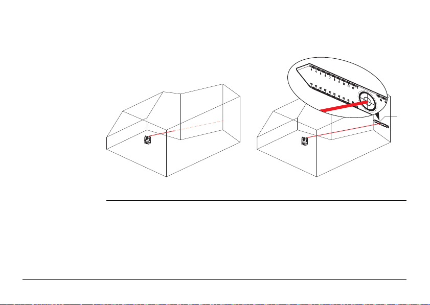
6. Press to measure hidden points. Place the tip of the ruler on the hidden point
to measure offset points.
• Target laser point on the mark at the opposite end of the ruler.
•Press .
• Target second mark.
•Press .
• A pop-up with confirms successful measurement.
7. Press to take pictures for documentation purposes. They are stored with
name, point ID, date, and time information.
8. Press in dark conditions to change Viewfinder picture to negative mode.
Edges and corners will be highlighted in black. Only available in Microsoft
Windows version.
Do not move ruler from now on.
3D Disto, Operation
85
Page 86

3D Disto, Operation
9. Press to choose between different turn commands:
• Turn 90° right
•Turn 90° left
• Turn ?°: Enter the horizontal angle by which the 3D Disto should turn.
• Horizon: 3D Disto goes to 0% slope/horizontal position.
• Plumb up: This option can be used to plumb up a point by setting up the
3D Disto exactly over it. Just mark a cross on the floor. Ensure that the lines of
the cross are at exactly 90° to each other and long enough to be seen when
setting up the instrument above. Use the 90° markings on the 3D Disto socket
for centering.
Please note that there are vertical and horizontal deviations in the
movements. Do not use the turn commands for stake-out or alignment. Please work with tools from the Tool Kit instead.
86
Page 87

6.3 Measurement Workflow
3D Disto_050
1
2
3
4
5
6
Description The Measure application allows determination of horizontal distances, tie distances,
Measurements
step-by-step
3D Disto, Operation
height differences, heights, angles, areas, volumes, slopes, or the perimeter of
points indoors but also outdoors on buildings and sites.
87
Page 88

3D Disto, Operation
To measure for example a rooms’ dimension, carry out the following steps:
1. Start-up the system as described in "5.1 Start-up Procedure".
2. The following screen
appears:
3. To target the first point, for example a corner, press and use the arrow
keys or another method as described in "6.2 Viewfinder", to move the laser point
to the desired position.
While targeting ensure the laser beam is not split along corners or
edges. Otherwise this could lead to wrong measurements.
If laser point becomes a line due to an acute target angle to a wall the
system measures with the centre of the line.
88
Page 89

4. Press to measure. Measured point appears in the sketch area.
5. Target the second
point and proceed as
described in steps 3. to
4. A line is displayed
from the first to the
second measured
point.
Measurement errors can occur when measuring toward clear liquids,
for example water, or dust free glass, Styrofoam, or similar semipermeable surfaces. Measurement time may increase when measuring
to non-reflective and dark surfaces.
The position of the 3D Disto symbol in the sketch changes in correct
relation to the measured point. The first measured point is always
displayed on the left side of the sketch area.
3D Disto, Operation
89
Page 90

3D Disto, Operation
90
6. After the third point is
measured a proposed
"closing line" appears
between the first and
last measured point.
The selected line is
always highlighted with
a bold line and an
arrow in the direction
of measurement.
7. Proceed as described for measuring further points or use to close/finish the
polygon.
In special situations the proposed line is not available. Polygons can
also be closed and results created by drawing a line with the stylus
between the two points to be connected.
Page 91

8. To measure the room
height select a floor
point in the sketch
area. Then target and
measure the ceiling
corner above it.
3D Disto, Operation
9. Proceed as described previously to measure the ceiling dimensions.
10. Press to undo the last command.
11. Press to redo the last command.
12. Press or and to clear measurements and results.
13. Press to choose between save, save as, clear screen, or cancel.
Please note that the sketch shows a foot print view. Measured floor
and ceiling points may cover each other. Use or to select points
and get the height result.
91
Page 92

3D Disto, Operation
92
It might be better to organise the measurements in different folders to
keep the amount of data in one folder at a meaningful limit for both
working and for export.
Page 93

6.4 Touch Screen in Sketch Area
Selection of
elements
Line drawing
between arbitrary
points
3D Disto, Operation
Any element can be selected by fingertip or by stylus. Polygons that consist of added
or subtracted lines cannot be selected by direct touch.
This is a feature to determine results, not to draw a line.
The key of the Toolbar only accepts a line proposed by the system. These
proposed lines are always connected to the last measured point.
With the Line drawing between arbitrary points feature two points can be
connected that were not measured in sequence.
93
Page 94

3D Disto, Operation
7 7
3D Disto_047
94
1. Select point. 2. Keep finger or stylus
on screen and slide to
desired point.
3. Release touch screen
when dotted line
changes to dashed
line. Results between
these two points are
displayed in the results
window.
Page 95

6.5 Addition and Subtraction
Addition and
subtraction after
measurement
step-by-step
3D Disto, Operation
During and after measuring you can add or subtract selected elements.
The following values can be added:
• Horizontal distances
• Tie distances
Area and volume results can be added or subtracted by using the memory function
in the calculator.
1. Select element by fingertip, stylus or / .
2. Press or for addition or subtraction. The corresponding symbol appears
in the status bar. The first selected line or area is highlighted with black bullet
symbol.
3. Select next element and press or for addition/subtraction again or to
close the sum and/or finish the adding/subtracting function.
95
Page 96

3D Disto, Operation
96
4. The added/subtracted
elements get a or
icon.
5. The sum is displayed in
the results window.
Addition and
subtraction during
measurement
step-by-step
1. Press , target and measure the first two points with .
2. Two points with a line connection appear in sketch area.
3. Press or for addition or subtraction. The corresponding symbol appears
in the status bar. The first selected line is highlighted with black bullet symbol.
4. Press , target to measure a further point. Press .
You have to measure two points before or is active as points
cannot be added or subtracted.
Page 97

5. Press or to add/subtract next distance (line) or continue measuring if you
would like to skip a point distance to be added/subtracted.
6. Proceed until ready to close the sum and/or finish the adding/subtracting func-
tion. Then press .
3D Disto, Operation
97
Page 98

3D Disto, Operation
6.6 Area & Volume Calculations
98
Description The 3D Disto can also help determine areas and volumes. Both can be determined
during or after measuring.
1. Press and choose .
2. A pop-up offers the
choices horizontal
area/volume, tilted
area/volume, or quit
the application. The
sketch areas' content
is retained but the
Toolbar changes.
Each area can be managed in both the Horizontal Area or Tilted Area application.
Page 99

6.6.1 Horizontal Areas/Volumes
Calculation during
measurement
step-by-step
3D Disto, Operation
1. Either select start point in sketch area or open Viewfinder if sketch is empty.
2. Target and measure a point with . Viewfinder is closed and point displayed
in sketch.
3. Press and measure next point with .
4. Press to define line as part of the area. Proceed with measurement and line
selection. The polygon can be closed by pressing . The area is highlighted in
grey.
5. Pop-up appears to choose between the different options to define the height:
Enter height for volume, Measure height, Cancel.
6. Measure height:
Viewfinder opens, target and measure point on floor with , followed by
point on ceiling. The height appears in the results window.
OR:
7. Enter height:
Default for the entry is 0.000 m. Enter a desired value and press OK or Cancel.
You can measure the points anywhere on the floor or ceiling area.
99
Page 100

3D Disto, Operation
100
OR:
8. Cancel: the result is an area.
9. To change the height or to calculate the volume with a selected area press
and proceed as described in steps 3. to 4.
Calculation after
measurement
step-by-step
1. Select line to be added to area and press .
2. Proceed that way for all lines and press .
3. For volume calculations go on as described from 5. to 9., page 99.
4. Quit application by pressing .
 Loading...