

Page 1
Instruction manual
Leica CM1510 S – Cryostat
V1.4 English – 04/2010
Always keep this manual near the instrument.
Read carefully prior to operating the instrument.
/HLFD&0 6
Cryostat
Page 2

Page 3

NOTE
The information, numerical data, notes and
value judgments contained in this manual represent the current state of scientific knowledge and state-of-the-art technology as we
understand it following thorough investigation
in this field.
We are under no obligation to update the
present manual according to the latest technical developments, nor to provide our customers with additional copies, updates etc. of
this manual.
For erroneous statements, drawings, technical illustrations etc. contained in this manual
we exclude liability as far as permissible according to the national legal system applicable
in each individual case. In particular, no liability whatsoever is accepted for any financial
loss or consequential damage caused by or
related to compliance with statements or other
information in this manual.
Statements, drawings, illustrations and other
information as regards contents or technical
details of the present manual are not to be
considered as warranted characteristics of
our products.
These are determined only by the contract
provisions agreed between ourselves and our
customers.
Leica reserves the right to change technical
specifications as well as manufacturing processes without prior notice. Only in this way is
it possible to continuously improve the technology and manufacturing techniques used in
our products.
This document is protected under copyright
laws. Any copyrights of this document are retained by Leica Biosystems Nussloch GmbH.
Any reproduction of text and illustrations (or of
any parts thereof) by means of print, photocopy, microfiche, web cam or other methods –
including any electronic systems and media –
requires express prior permission in writing by
Leica Biosystems Nussloch GmbH.
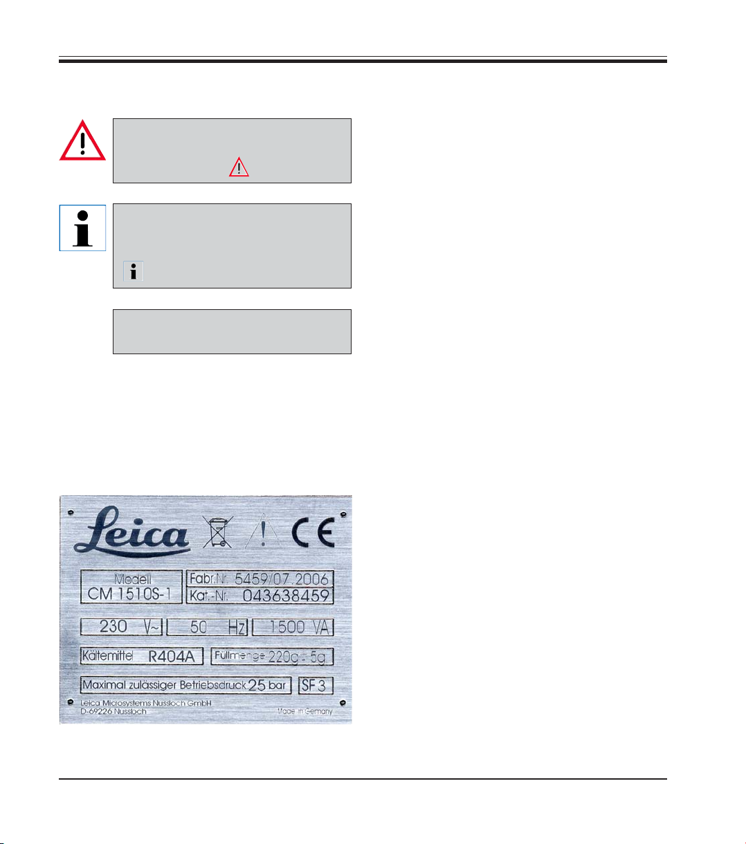
For the instrument serial number and year of
manufacture, please refer to the name plate at
the back of the instrument.
© Leica Biosystems Nussloch GmbH
Published by:
Leica Biosystems Nussloch GmbH
Heidelberger Str. 17 - 19
D-69226 Nussloch
Germany
Phone: +49 (0)62 24 143-0
Fax: +49 (0)62 24 143-268
eMail: histo_info@leica-microsystems.com
Internet: http://www.leica-microsystems.com
Leica CM1510 S – Cryostat
3
Page 4

Table of contents
1. Important information ................................................................................................................ 6
1.1 Symbols used in the text and their meaning .......................................................................................... 6
1.2 Instrument type ............................................................................................................................................. 6
1.3 Designated use ............................................................................................................................................. 6
1.4 Qualification of personnel .......................................................................................................................... 6
2. Safety ............................................................................................................................................ 7
2.1 Safety instructions ....................................................................................................................................... 7
2.2 Dangers, warnings and cautions .............................................................................................................. 7
2.3 Safety features............................................................................................................................................11
2.3.1 Locking the handwheel ............................................................................................................................. 11
2.3.2 Knife guard ...................................................................................................................................................11
3. Instrument components and specifications ........................................................................ 12
3.1 Overall view - instrument parts ................................................................................................................12
3.2 Technical data ............................................................................................................................................ 14
4. Setup ........................................................................................................................................... 16
4.1 Installation site requirements .................................................................................................................. 16
4.2 Standard delivery - packing list ............................................................................................................... 17
4.3 Unpacking and installation ...................................................................................................................... 18
4.4 Fastening the handwheel ......................................................................................................................... 19
4.5 Electrical connection ................................................................................................................................20
4.6 Prior to operation ........................................................................................................................................20
5. Operation .................................................................................................................................... 22
5.1 Control panel ............................................................................................................................................... 22
5.2 Controller ...................................................................................................................................................... 23
5.3 Setting user-definable parameters.........................................................................................................24
6. Daily work with the instrument ............................................................................................. 26
6.1 Specimen freezing ...................................................................................................................................... 26
6.1.1 Quick-freeze shelf.......................................................................................................................................26
6.2 Inserting the specimen discs .................................................................................................................. 26
6.2.1 Fixing the specimen discs in the specimen head ............................................................................... 27
6.2.2 Specimen orientation ................................................................................................................................ 27
6.3 Inserting the knife or blade into the knife holder ............................................................................... 27
6.4 Sectioning / trimming ................................................................................................................................. 28
6.4.1 Moving the specimen with the coarse / precision feed ....................................................................29
6.4.2 Section thickness setting ......................................................................................................................... 29
6.5 Defrosting ..................................................................................................................................................... 30
6.5.1 Automatic defrosting of the cryochamber ............................................................................................ 30
6.5.2 Manual defrosting of the cryochamber ................................................................................................ 30
6.5.3 Manual defrosting of the quick-freeze shelf ....................................................................................... 31
4
Instruction manual V1.4 – 04/2010
Page 5

Table of contents
6.6 Finishing work..............................................................................................................................................31
6.6.1 Finishing the daily work .............................................................................................................................31
6.6.2 Shutdown for a longer period ..................................................................................................................32
6.7 Temperature selection chart ................................................................................................................... 33
7. Troubleshooting ....................................................................................................................... 34
7.1 Possible causes and remedies ............................................................................................................ 34
7.2 Display error messages ......................................................................................................................... 38
7.3 Thermal circuit breaker (120V model only)....................................................................................... 3 8
8. Cleaning and maintenance .................................................................................................... 39
8.1 General maintenance instructions ..................................................................................................... 39
8.2 Automatic circuit breaker...................................................................................................................... 40
8.3 Cleaning ...................................................................................................................................................... 4 1
8.3.1 Spray disinfection with Leica Cryofect.............................................................................................. 4 1
8.4 Removing the microtome........................................................................................................................ 4 3
8.5 Removing the microtome housing ....................................................................................................... 4 4
8.6 Reinstalling the microtome .................................................................................................................... 45
8.7 Replacing the fuses ................................................................................................................................. 46
8.8 Replacing the lamp .................................................................................................................................. 47
9. Optional accessories ..............................................................................................................48
9.1.1 Mobile heat extractor ............................................................................................................................. 4 8
9.1.2 Stationary heat extractor ...................................................................................................................... 48
9.1.3 Thermal block............................................................................................................................................ 4 9
10. Warranty and service.............................................................................................................. 53
11. Decontamination Certificate (master) ...................................................................................54
12. Information for the People´s Republik of China ................................................................ 56
Leica CM1510 S – Cryostat
5
Page 6
1. Important information
1.1 Symbols used in the text and their meaning
Dangers, warnings and cautions appear in a gray box and are marked by
a warning triangle .
Notes, i.e. important user information appear in a gray box and are
marked by an information symbol
.
(5)
Figures in brackets refer to item nos.
in drawings.
1.2 Instrument type
All information provided in this manual applies
only to the instrument type indicated on the title
page.
1.3 Designated use
The Leica CM1510S is a powerful cryostat for
routine and research applications in biology,
medicine and industry, where it serves for
quick-freezing and subsequent sectioning of
specimen material.
The instrument is not designed for unattended
storage of specimen material.
The instrument must be operated only according to its designated use (see description
above) and according to the instructions contained in this manual.
Any other use of the instrument will be considered improper.
1.4 Qualification of personnel
• Der Leica CM1510 S may be operated only
by trained laboratory personnel.
• All laboratory personnel designated to operate the Leica CM1510 S must read this instruction manual carefully and must be familiar with all technical features of the
instrument before attempting to operate the
Leica CM1510 S.
A name plate indicating the serial number of
the instrument is attached to the back of the
instrument.
Fig. 1
6
Instruction manual V 1.4 – 04/2010
Page 7
Be sure to comply with the safety instructions and warnings in this chapter. Be sure to read
these instructions, even if you are already familiar with the operation and use of other
Leica products.
2.1 Safety instructions
2. Safety
This instruction manual contains important instructions and information regarding the operational safety and maintenance of the instrument.
The instruction manual is an important part of
the product, which must be read carefully prior to setup and use and must always be kept
near the instrument.
If additional requirements on accident prevention and environmental
protection exist in the country of operation, this instruction manual must
be supplemented by appropriate instructions to ensure compliance
with such requirements.
This instrument was built and tested in accordance with the safety regulations for electrical
measuring, control, regulating and laboratory
devices.
For current information about applicable standards, please refer to the CE declaration of
conformity on our Internet site:
www.leica-microsystems.com
In order to maintain this condition and ensure
safe operation, the operator must observe all
the instructions and warnings contained in
this instruction manual.
2.2 Dangers, warnings and cautions
The safety devices installed in this instrument by the manufacturer only constitute the basis for accident prevention. Primarily responsible for accident-free operation is above all
the institution which owns the instrument and, in addition, the designated personnel who
operates, services or repairs the instrument. To ensure trouble-free operation of the instrument, be sure to comply with the following instructions and warnings.
The protective devices on both instrument and accessories must neither be removed nor
modified.
Only authorized and qualified service personnel may repair the instrument and access the
instrument’s internal components.
Leica CM1510 S – Cryostat
7
Page 8
2. Safety
Warnings - Transport and installation
The instrument must be transported either in an upright position or, if inclined, at an angle
of max. 30 degrees!
Do not operate in rooms with explosion hazard!
To ensure the instrument works trouble-free, the instrument must be set up with a least 10
cm distance from all walls and furniture.
Do not place anything next to the compressor ventilation grid (right side of the cabinet) to
ensure adequate ventilation!
The protective foam parts between microtome and compressor MUST be removed prior to
operating the instrument!
Warnings - Electrical connection
Please refer to and comply with the ‘Technical data‘!
The instrument must be connected to a grounded mains power outlet socket!
During the start-up of the compressor the nominal voltage must not drop below the values
specified in the ‘Technical Data‘ chapter!
The compressor requires a start-up current between 45 and 50 A.
Therefore, the electric circuit at the installation site must be inspected by a qualified electrician to ensure that it meets the requirements for a smooth operation of the instrument.
For trouble-free operation, a constant power supply according to specification must be ensured at all times. Failure to comply with the above will cause damage to the instrument.
After transporting, wait at least 4 hours before switching the instrument on!
This waiting period is necessary to allow the compressor oil, which may have been displaced during transport, to return to its original position.
Failure to comply with this can cause severe damage to the instrument.
8
Instruction manual V1.4 – 04/2010
Page 9
Warnings - sectioning
Be careful when handling microtome knives and disposable blades. The cutting edge is extremely sharp and can cause severe injury!
Never leave knives/blades or knife holders with a knife/blade mounted lying around!
Always store knives in the knife box when not in use!
Never place a knife anywhere with the cutting edge facing upwards!
NEVER try to catch a falling knife!
Always clamp the specimen before the knife!
Be careful when picking up the sections! The cutting edge is exposed!
When working inside the cryochamber, keep hands away from gilled evaporator – high risk
of injury from sharp edges!
Prior to manipulating knife and specimen, when changing the specimen or during breaks,
always lock the handwheel and cover the cutting edge with the knife guard!
2. Safety
Avoid skin contact with cold parts of the instrument as this can cause frostbite!
Cleaning and disinfection
Do not use organic solvents or any other aggressive substances for cleaning and disinfection! The instrument is suitable for spray disinfection with Leica Cryofect!
Only use alcohol or commercial disinfectants based on alcohol for disinfection!
For spray disinfection follow the instructions for use supplied with the disinfectant!
Do not use any external heaters for drying the cryochamber. This can cause severe damage
to the heating system!
Leica CM1510 S – Cryostat
9
Page 10
2. Safety
Warnings - maintenance
Only qualified and authorized service personnel may access the internal components of the
instrument for service and repair.
Clean the compressor ventilation grid at least once a year or more often if required!
Replacing the fuses:
Before replacing the fuses, turn off the instrument mains switch and pull the mains plug!
Only use replacement fuses of the same specification. For the required values, please refer
to chapter 3.2 ‘Technical Data‘!
Replacing the fluorescent light lamp:
Before replacing the lamp, turn off the instrument mains switch and pull the mains plug!
If the lamp is broken, it must be replaced by the technical service, as the replacement procedure involves a high risk of injury!
Do not use any lamp type other than the one inserted by the manufacturer!
Removing the microtome from the cryochamber
Prior to removing the microtome turn off the instrument mains switch and pull the mains
plug.
Before removing the microtome, rotate the handwheel until the specimen cylinder is positioned in the lowest position. Otherwise, when removing the microtome, the specimen head
will rapidly fall down and might injure the operator’s hands!
Wear appropriate protective gloves to remove the cold microtome from the cryochamber.
Prolonged skin contact with cold parts of the instrument can cause frost bite!
The microtome must be completely dry before reinstallation. Humidity inside the microtome
will condense and freeze in the cold cryostat and thus may cause malfunctions or damage!
10
Instruction manual V 1.4 – 04/2010
Page 11
2.3 Safety features
The instrument is equipped with the following safety features: handwheel locking mechanism and knife guard on knife holder.
The consistent use of these safety features and strict observation of
the safety instructions and warnings in this manual will safeguard the
operator from accidents and/or personal injury to a great extent.
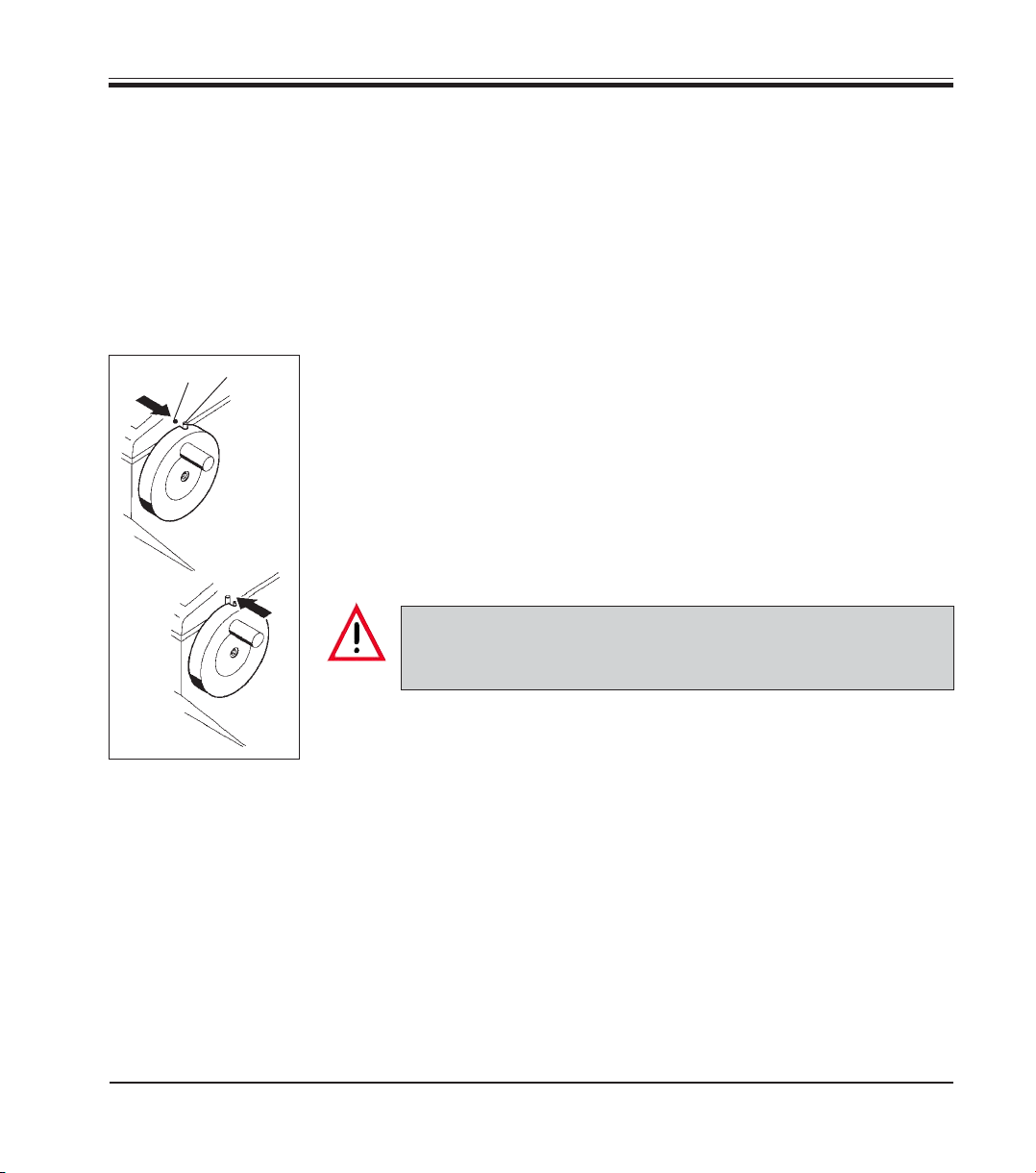
2.3.1 Locking the handwheel
2
1
To lock the handwheel, rotate the handwheel until the handle is in the
upper position and the metal pin (1) is located opposite the black dot (2).
Push the metal pin outward into the recess at the handwheel; if necessary move the handwheel slightly back and forth, until you feel that the
locking mechanism engages.
To unlock the handwheel, push the metal pin (1) out of the recess at the
handwheel, towards the cryostat housing.
2. Safety
2.3.2 Knife guard
Leica CM1510 S – Cryostat
Prior to manipulating knife and specimen, when changing the
specimen or during breaks, always lock the handwheel and
cover the cutting edge with the knife guard!
Fig. 2
Knife holder CN is equipped with a knife guard; on the knifeholder CE, the
glass plate of the anti-roll guide constitutes the knife guard (see separate instruction manual for your knife holder).
11
Page 12
3. Instrument components and specifications
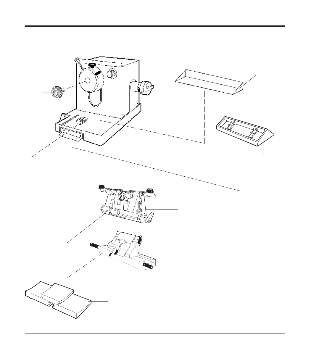
3.1 Overall view - instrument parts
Specimen
disc
Section
waste tray
Brush shelf
Fig. 3
12
Knife holder CN
Knife holder CE
Knife holder base
Instruction manual V 1.4 – 04/2010
Page 13
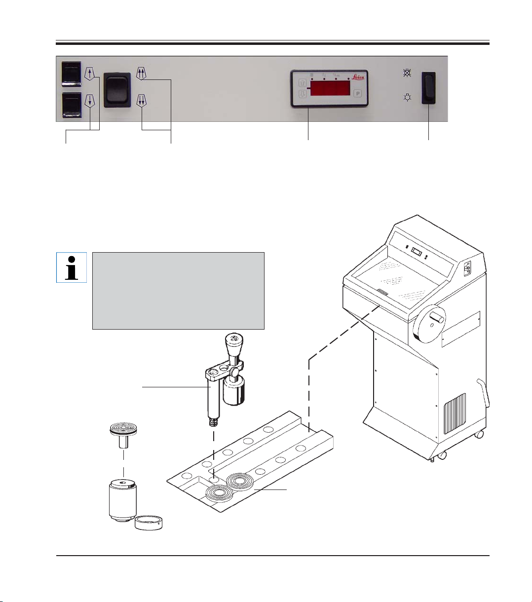
3. Instrument components and specifications
Motorized coarse feed
forward or
backward
- slow
Use the motorized coarse feed to rapidly move
the specimen head towards or away from the
knife.
Carefully observe the specimen
when moving it towards the cutting
edge to avoid an accidental collision of the specimen with the knife
edge, which can cause severe damage to both knife and specimen.
forward
or backward
- fast
Display indicating:
- Set / actual temperature
- Real time
- Defrost time
Fig. 4
Control
panel
On/Off switch
for cryochamber
illumination
Heat extractor
Thermal
block
(optional
accessory)
Leica CM1510 S – Cryostat
Quick-freezing shelf
13
Page 14

3. Instrument components and specifications
3.2 Technical data
Operating temperature range from +18 °C to +35 °C. All specifications related to temperature
are based on an ambient temperature of +22 °C and maximum air humidity of 60%!
Type CM1510S CM1510 S CM1510S
Nominal voltage 100 V AC ±10% 120 V AC ±10% 230 V AC ±10%
Nominal frequency 50/60 Hz 60 Hz 50 Hz
Power draw 2000 VA 1300 VA 1500 VA
Protective class I I I
Mains fuses Automatic circuit Automatic circuit Automatic circuit
breaker T 20 A breaker T 15 A breaker T 10 A
Pollution degree 2 2 2
Overvoltage inst. category II II II
Power draw 495 W / 850 W 850 W
Refrigerating output
at evaporator temperature 470 W / 780 W 780 W
of -25 °C
Nominal pressure 25 bar (maximum value)
Safety factor 3
Refrigerant 215 g ± 5 g R404A *
Compressor oil 0.6 l EMKARATE RL244b, ICI *
Refrigeration system 50 Hz 60 Hz
Temperature setting range 0 °C to -30 °C ±10%
at an ambient temperature of 22°C
_<
and air humidity
60 %
when sliding window is closed;
adjustable in 1-degree increments
Temperature of quick-freezing shelf Max. -44 °C
- at a temperature of -30 °C
Defrosting Automatic hot gas defrosting,
defrost time freely programmable,
manual defrosting of quick-freeze shelf and evaporator
duration: 8 min.
* Refrigerant and compressor oil must be replaced by authorized service personnel only!
495 W
470 W
14
Instruction manual V 1.4 – 04/2010
Page 15
3. Instrument components and specifications
Microtome
Rotary microtome
Section thickness setting 1 -60 µm; in 1-µm steps from 1 to 10 µm
in 2-µm steps from 10 to 20 µm
in 5-µm steps from 20 to 60 µm
Total horizontal specimen feed 25 mm
Vertical stroke 59 mm
Maximum specimen size 55 x 55 mm
Specimen orientation 8° (x-, y-, z-axis)
Electrical coarse feed
slow 0.2 µm/s
fast 0.7 µm/s
Cryocabinet
Dimensions
Width (w/o handwheel) 880 mm
Width (with handwheel) 680 mm
Depth 680 mm
Height (arm rests) 1010 mm
Height (overall) 1175 mm
Please refer to chapter 4.1 - ‘Installation site requirements’!
Weight (incl. microtome) approx. 135 kg
Lamp
50 Hz version: Osram Dulux S 11 W/21, light color LUMILUX bright white
60 Hz version: Osram Dulux S 13 W/21, light color LUMILUX bright white
All CM1510S instrument types require the following secondary fuses:
F4: T0.5 A 6.3 x 32 mm; Fa. Schurter, Typ FST; Fa. Littlefuse, Typ 313
F5: T1.0 A 6.3 x 32 mm; Fa. Schurter, Typ FST; Fa. Littlefuse, Typ 313
F6: T2.0 A 6.3 x 32 mm; Fa. Schurter, Typ FST; Fa. Littlefuse, Typ 313
F7: T4.0 A 6.3 x 32 mm; Fa. Schurter, Typ FST; Fa. Littlefuse, Typ 313
F8: T2.0 A 6.3 x 32 mm; Fa. Schurter, Typ FST; Fa. Littlefuse, Typ 313
Leica CM1510 S – Cryostat
15
Page 16
4. Setup
4.1 Installation site requirements
Do not operate in rooms with explosion hazard!
To ensure the instrument works trouble-free, the instrument must be set up with at least 10
cm distance from all walls and furniture.
Do not place anything next to the compressor ventilation grid (right side of the cabinet) to
ensure adequate ventilation!
The place of installation must meet the following requirements:
• no direct sunlight,
• mains power socket at a distance no greater than 2.5 m (length of
power cord = 2.5 m) - no extension cords must be used!
• no drafts (air condition outlets etc.),
• even floor,
• virtually vibration-free floor,
• handwheel freely and easily accessible,
• room temperature maximum 35 °C, (< 22 °C recommended),
• relative humidity max. 60 %,
• only for indoor use.
16
High room temperature and excessive air humidity at the installation site affect the cooling
capacity of the cryostat.
Instruction manual V1.4 – 04/2010
Page 17

4.2 Standard delivery - packing list
1 Basic instrument .................................................................... 14 0436 38461
1 Stationary heat extractor ..................................................... 14 0369 11197
1 Handwheel with marking, antibacterial ........................... 14 0471 42558
1 Optional clamping lever for object head .......................... 14 0112 28806
1 Set of specimen discs ........................................................... 14 0470 43550
-4 Specimen discs, 25 mm .................................................... 14 0416 19275
-4 Specimen discs, 30 mm .................................................... 14 0370 08587
1 Adapter for Miles Tissue Tek specimen discs ................ 14 0436 26747
1 Section waste tray ................................................................. 14 0471 30787
1 Storage shelf, right ................................................................. 14 0471 30789
1 Storage shelf, left ................................................................... 14 0436 38503
1 Brush shelf............................................................................... 14 0398 13088
1 Tool set: .................................................................................... 14 0436 43463
-1 Brush, fine ........................................................................... 14 0183 28642
-1 “Leica” brush w/magnet ................................................. 14 0183 40426
-1 Allen key, size 1.5 ............................................................... 14 0222 10050
-1 Allen key, size 2.5 ............................................................... 14 0222 04137
-1 Allen key, size 3.0 ............................................................... 14 0222 04138
-1 Allen key, size 4.0 ............................................................... 14 0222 04139
-1 Allen key with spherical head, size 4.0 ......................... 14 0222 32131
-1 Allen key, size 5.0 ............................................................... 14 0222 04140
-1 Allen key with handle, size 5.0 ........................................ 14 0194 04760
-1 Allen key, size 6.0 ............................................................... 14 0222 04141
-1 Single-head wrench, size 13 .......................................... 14 0330 33149
-1 Single-head wrench, size 16 .......................................... 14 0330 18595
1 Bottle of cryostat oil, type 407, 50 ml .................................. 14 0336 06098
1 Bottle of OCT-Compound, mounting medium
for cryosectioning, 125 ml .................................................... 14 0201 08926
1 Instruction manual Leica CM1510 S - G/E/F/S ................. 14 0436 80001
4. Setup
Order no.
Leica CM1510 S – Cryostat
17
Page 18

4. Setup
4.3 Unpacking and installation
Unpacking as per the unpacking instructions attached to the outside of
the instrument shipping crate.
Instrument
rear wall
The instrument must be transported either in an upright position
or slightly inclined, at an angle of max. 30 degrees!
When pushing the instrument, do not grip the cabinet at the lid.
Grip the cabinet only at the marked areas ( )!
• Use the size 16 fork wrench (1) to completely screw in the adjustable feet.
• Move instrument to installation site on rollers (2 and 3).
• The adjustable feet (1) can be used to
slightly tilt the instrument (max. 30 degrees).
• To lift the instrument please use the handle
straps provided attaching them to the front
(2) and rear rollers (3).
• At the installation site, unscrew the adjustable feet (1) with the fork wrench to ensure
stability.
• Align the adjustable feet to level the instrument.
18
Fig. 5
After transporting, wait at least 4
hours before switching the instrument on!
This waiting period is necessary to
allow the compressor oil, which may
have been displaced during transport, to return to its original position.
231
Instruction manual V 1.4 – 04/2010
Page 19

4. Setup
4.4 Fastening the handwheel
2
1
3
4
Fig. 6
The handwheel is lockable with the handle in
the upper position.
5
The handwheel and all hardware
items needed to attach it to the cryostat are packed in the accessory
box. The handwheel can be dismounted e.g. for transport through
narrow doors.
• Insert the pin (1) of the handwheel shaft
into the bore (2) of the handwheel.
• Place spring washer (3) onto screw (4) with
the curved surface pointing to the right side
(see also Fig. 6).
• Tighten screw (4) with the size 6 Allen key.
To disassemble, proceed in reverse order.
The protective foam parts between
microtome and compressor MUST be
removed prior to operating the instrument (see Fig. 7)!
Fig. 7
Leica CM1510 S – Cryostat
Caution! Edges of gilled evaporator
are extremely sharp! High risk of injury!
19
Page 20

4. Setup
4.5 Electrical connection
• Protect the electric circuit at the place of installation separately.
• Do not connect any other consumers to this electric circuit.
4.6 Prior to operation
• Verify if mains voltage and frequency in your laboratory comply with
• Place the storage shelves into the chamber.
• Insert section waste tray (1) and brush shelf (2).
• Place the knife holder base on the microtome base plate and clamp.
• Mount the knife holder onto the knife holder base and clamp (see
1
• Open the knife box with the knife and place the open box into the
• Place all tools needed for specimen preparation into the
• Close the sliding window.
• Connect the mains plug to the wall outlet socket.
During the start-up of the compressor the nominal voltage must
not drop below the values specified in the ‘Technical Data‘!
The compressor requires a start-up current between 45 and 50 A.
Therefore, the electric circuit at the installation site must be inspected by a qualified electrician to ensure that it meets the requirements for a smooth operation of the instrument.
For trouble-free operation, a constant power supply according to
specification must be ensured at all times.
Failure to comply with the above will cause damage to the instrument.
the power rating indicated on the name plate of the instrument!
separate instruction manual for your knife holder).
cryochamber for precooling.
cryochamber.
Fig. 8
20
2
After transporting, wait at least 4 hours before switching the instrument on!
This waiting period is necessary to allow the compressor oil,
which may have been displaced during transport, to return to its
original position.
Failure to comply with this can cause severe damage to the instrument.
Instruction manual V 1.4 – 04/2010
Page 21

4.6.1 Mains switch and automatic circuit breaker
The automatic circuit breakers (mains fuses) are also used as mains
switch.
To turn the automatic circuit breaker on, flip it to the upper position. To
disconnect, set the circuit breaker in the lower position.
Fig. 9
The temperature controller display first reads the actual temperature of
the cryochamber.
After the instrument mains switch has been switched on, it will
take about 5 seconds until the compressor starts operating.
Bear in mind the required minimum switch-off period!
4. Setup
Leica CM1510 S – Cryostat
• Turn the automatic circuit breaker on. The instrument is initialized.
• The factory configuration settings are as follows:
Real time: 00:00
Defrost time: 23:50 (adjustable, see chapter 5.2)
Chamber cooling: on
(temperature indication)
21
Page 22

5. Operation
5.1 Control panel
Motorized coarse feed
Forward / backward
- fast
Fig.10
Forward/
backward
Fig.11
- slow
away from knife
towards the knife
Display indicating:
- Set / actual temperature
- Real time
- Defrost time
On/Off switch
for cryochamber
illumination
Motorized coarse feed
The motorized coarse feed moves the specimen towards or away from the knife!
The fast specimen movement towards the cutting edge must be observed carefully to prevent the specimen from colliding with the cutting edge as this can cause severe damage to
both the knife and the specimen!
22
Instruction manual V 1.4 – 04/2010
Page 23

5.2 Controller
5. Operation
Fig. 12
Defrosting the chamber
1
The controller has a 3-digit display, with additional LEDs and three function keys.
indicates activation of cooling mode
indicates activation of cryochamber
defrosting
indicates activation of quick-freeze
shelf defrosting
(LED 1, Fig. 12) - no function allocated
User-definable parameters can be accessed
by pressing the P-button. Each programming
field is displayed for 30 seconds for entering
new parameter settings. After that time the
display automatically resets to actual temperature indication. Parameters can be modified
via the arrow keys:
Fig. 13
The duration of the cryochamber and quick-freeze shelf defrost cycles is set to 8 minutes in
the factory.
Leica CM1510 S – Cryostat
(LED 1 and LED 2 ON)
+
• (Press and hold „P“ button and also press
„Arrow up“).
Press the two buttons once again to deac-
tivate the defrost function.
23
Page 24

5. Operation
Defrosting the quick-freeze shelf
Fig. 14
5.3 Setting user-definable parameters
Set temperature:
(LED 1 and LED 3 on)
• (Press and hold „P“ button and simultaneously press
).
Press the two buttons once again to deac-
tivate the defrost function.
During normal operation, the actual
cryochamber temperature is displayed.
• Press once.
Fig. 15
Defrost time:
Fig. 16
24
• Press
or to select the desired tem-
perature.
• Press once more.
• Press
or to modify the indicated
value.
The first two digits correspond to the hours,
the last digit indicates minutes. Since there is
only one digit indicating minutes, the indicated
value must be multiplied by 10. Defrost time is
selectable in 10-minute steps.
Fig. 16 shows defrosting time set at 23:50
hours.
Instruction manual V 1.4 – 04/2010
Page 25

Real time:
5. Operation
• To set real time, press once more.
Fig. 17
Fig. 18
Code parameter:
• Press
or to modify the indicated
value (hour).
• Press
• Press
again.
or to modify the indicated
value (minutes).
• If ‘P‘ is pressed once more, the display
reads ‘C00‘. In this mode a code needs to
be entered.
Code parameter settings may be accessed only by authorized technical
service personnel.
Fig. 19
Minimum switch-off period
When the instrument is switched on (via mains plug), the compressor
starts operating after approx. 5 secs. If the compressor does not switch
on after that period of time, the
the period during which the instrument was switched off was too short.
(Safety meaure to avoid major instrument damage).
Leica CM1510 S – Cryostat
• Press ‘P‘ again to return set temperature indi-
cation, or wait 30 seconds until the display indication returns to actual temperature.
LED will start blinking, indicating that
25
Page 26

6. Daily work with the instrument
6.1 Specimen freezing
6.1.1 Quick-freeze shelf
The cryochamber is equipped with a quick-freezing shelf (Fig. 20) for up
to 10 specimen discs.
When working inside the cryochamber, keep hands away from
gilled evaporator – high risk of injury from sharp edges!
Fig. 20
Specimen freezing
• Cut the specimen to size.
The specimen block should not be any bigger than 2x2cm.
• Use a specimen disc at room temperature.
• Apply a sufficient quantity of cryocompound to the disc.
• Place the specimen on the disc and orient.
• Remove the cover from the quick-freeze shelf.
• Place the specimen disc with the specimen in one of the bores of the
quick-freeze shelf and freeze the specimen.
Specimen freezing on the quick-freeze shelf can be accelerated
by additionally using a mobile or a stationary heat extractor.
• Once the specimen is frozen, insert the specimen disc in the specimen head and start sectioning.
6.2 Inserting the specimen discs
Specimen discs are available in three sizes (ø 20, 25, 30 mm). The
1
grooved surface ensures firm contact with the specimen.
• A black dot (1) helps orienting the specimen.
Fig. 21
26
Instruction manual V1.4 – 04/2010
Page 27

6. Daily work with the instrument
6.2.1 Fixing the specimen discs in the specimen head
• Lock handwheel with handle in upper posi-
Fig. 22
1
3
2
45
tion.
• If the knife holder and a knife are in place,
cover the knife edge with the knife guard.
• Loosen clamping screw (1) on the specimen head.
• Insert the shaft of the specimen disc (3)
with the frozen specimen into the opening
(2) of the specimen head.
Make sure that the shaft of the specimen disc
is fully inserted. The entire rear surface of the
specimen disc must fit closely against the
specimen head.
• Retighten clamping screw (1).
6.2.2 Specimen orientation
• Loosen screw (4).
• Use lever (5) to orient the specimen on the ball socket.
• Retighten screw (4).
6.3 Inserting the knife or blade into the knife holder
All components of the cryostat as well as the knife or blade and
the tools for specimen preparation should be precooled in the
cryostat before starting sectioning.
• Insert the precooled knife or blade in the knife holder and clamp.
For further details on how to handle the knife holder, please refer to the
separate instruction manual for your knife holder.
Leica CM1510 S – Cryostat
27
Page 28

6. Daily work with the instrument
6.4 Sectioning / trimming
For all settings on knife holder and anti-roll guide, please refer
to the separate instruction manual for your knife holder.
Be careful when handling microtome knives and disposable
blades. The cutting edge is extremely sharp and can cause severe injury!
• Remove the knife guard from the cutting edge.
• Remove anti-roll guide from knife.
• Insert precooled knife / blade into knife holder.
• Select appropriate clearance angle on knife holder. Settings between 4° - 6° (knife holder CN) and 1° to 2° (knife holder CE) are appropriate for most applications.
• Unlock the handwheel.
• Rotate the handwheel cautiously and check if the specimen comes
in contact with the cutting edge of the knife.
• Adjust knife / knife holder relative to the specimen.
• To trim the specimen, select a section thickness of approximately 30
µm with the section thickness selection knob on the front of the microtome.
• Trim the specimen to the desired sectioning plane, gradually decreasing the section thickness.
• Select the desired section thickness and start sectioning.
• During sectioning and for picking up the sections, place the anti-roll
guide on the knife and adjust relative to the cutting edge.
Readjust the anti-roll guide when necessary.
28
Instruction manual V1.4 – 04/2010
Page 29

6. Daily work with the instrument
6.4.1 Moving the specimen with the coarse / precision feed
The specimen movement towards the cutting edge must be observed carefully to avoid that the specimen collides with the
cutting edge which can cause severe damage both to the knife
and the specimen!
Fig. 23
• Press the coarse feed button for fast or slow specimen movement
towards the cutting edge.
6.4.2 Section thickness setting
To select the section thickness, rotate knob (1) to a setting between 1
and 60 µm:
from 0 - 10 µm in 1-µm steps,
1
Fig. 24
• Decrease section thickness continually down to the appropriate value.
After changing from one section thickness to another, the first two or three sections should be
rejected.
• When sectioning, turn the handwheel clockwise at a constant speed.
from 10 - 20 µm in 2-µm steps,
from 20 - 60 µm in 5-µm steps.
The graduation scale on the microtome reflects the selected section
thickness.
• Select the desired section thickness via the rotary knob on the microtome.
Start sectioning at approx. 20 µm.
Leica CM1510 S – Cryostat
29
Page 30

6. Daily work with the instrument
6.5 Defrosting
Defrosting the cryochamber actually means defrosting the evaporator
to prevent excessive frost buildup. The gilled evaporator is flushed with
hot gas during defrosting. The cryochamber itself is virtually frost-free
and does not need to be defrosted.
The condensation water produced during chamber defrosting is collected in a container located at the front of the cryostat cabinet.
After defrosting, drops of water remaining on the surface of the
quick-freeze shelf need to be wiped off manually with an absorbent cloth to prevent new frost buildup.
To make sure that the condensation water stemming from the defrost cycles drains into the waste container and to avoid the risk
of possible contamination, ensure that the drain hose of the cryostat is placed into an appropriate waste container at all times
during operation.
During the automatic cryochamber defrosting the quick-freeze
shelf continues to be cooled.
The maximum duration of a defrost cycle is 8 minutes. Defrosting
is, however, automatically terminated once the cryochamber has
reached a temperature of -5°C. Cooling turns back on automatically.
6.5.1 Automatic defrosting of the cryochamber
An automatic defrost cycle takes place once in 24 hours.
The time of the automatic defrost cycle is programmed via the control
panel.
6.5.2 Manual defrosting of the cryochamber
Once the manual defrost cycle is completed, the instrument automatically goes back to refrigeration mode.
In addition to the programmable automatic defrost cycle a manual
cryochamber defrost cycle can be activated when necessary (see
chapter 5.2, Fig. 13).
30
Instruction manual V1.4 – 04/2010
Page 31

6.5.3 Manual defrosting of the quick-freeze shelf
The quick-freeze shelf may become hot during defrosting!
Therefore, do not touch it!
If heavy frost builds up on the quick-freeze shelf, especially after spray disinfection (see chapter 5.2, Fig. 14), a manual defrost cycle (which can be
terminated at any time) should be started.
When the quick-freeze shelf is being defrosted (independently of the cryochamber temperature selected) frost will build up on specimen head, knife
holder and microtome. During defrosting, the chamber temperature will increase by approx. 8-10K. Due to the frost formation and change in temperature, specimen sectioning during the defrost cycle is not possible. After the
quick-freeze shelf defrosting cycle has been activated (1. defrosting, 2. wiping dry, 3. recooling) a waiting period of approx. 45 min. must be observed
before sectioning can be resumed. If the chamber temperature exceeds 5 °C, the defrosting cycle is interrupted.
6.6 Finishing work
6.6.1 Finishing the daily work
6. Daily work with the instrument
Leica CM1510 S – Cryostat
• Lock the handwheel.
• Take the knife/blade out of the knife holder and put it back into the
knife box.
• Remove frozen section waste with a cold brush.
• Empty the section waste tray.
• Clean the storage shelves and brush shelf.
Only common detergents and alcohol-based disinfectants
should be used for cleaning and disinfection.
All components removed from the cold environment will collect
condensation. Therefore they must be dried thoroughly before
placing them back into the cryochamber.
• Remove all specimens from the cryostat.
• Close the sliding window.
• Switch off the cryochamber illumination.
• Do not switch the instrument off with the automatic circuit breaker as
there would be no cooling.
31
Page 32

6. Daily work with the instrument
6.6.2 Shutdown for a longer period
If you do not intend to use the instrument for several weeks, you
may turn it off.
Please note, however, that it may take up to several hours to
cool the cryochamber down to very low temperatures after turning the instrument on again.
After turning off, the instrument should be cleaned and disinfected thoroughly
• Lock the handwheel.
• Take the knife/blade out of the knife holder. Put the knife back into the
knife box or push the blade into the receptacle for used blades provided at the bottom of the dispenser.
• Remove all specimen material from the cryochamber.
• Remove frozen section waste with a cold brush.
• Empty the section waste tray.
• Remove storage shelves and brush shelf for cleaning.
• Switch the instrument off with the automatic circuit breaker.
• Open the sliding window so that the cryochamber can dry out.
(see chapter. ‘8. Cleaning and maintenance’).
32
Switching off the instrument with the automatic circuit breaker will not
affect the programmed parameters.
Prior to switching the instrument back on, the cryochamber, the microtome and all other parts of the instrument must be completely dry.
Instruction manual V1.4 – 04/2010
Page 33

6. Daily work with the instrument
6.7 Temperature selection chart
Tissue -10 °C - -15 °C -15°C - -25°C -25 °C - -35 °C
Adrenal GG
Bone marrow G
Brain G
Bladder G
Breast, fatty G
Breast, little fat G
Cartilage GG
Cervical G
Fatty G
Heart and vascular G
Intestinal G
Kidney G
Laryngeal G
Lip G
Liver G
Lung G
Lymphoid G
Muscle G
Nose G
Pancreatic G
Prostate G
Ovarian G
Rectal G
Skin with fat G
Skin without fat G
Speenal or bloody tissue G
Testicular GG
Thyroid G
Tongue G
Uterus curettage G
The temperature values given above are based on long-term experience, however, these are only approximate values, as any tissue may require particular adjustments.
Leica CM1510 S – Cryostat
33
Page 34

7. Troubleshooting
7.1 Possible causes and remedies Problem Cause Remedy
Frost on chamber walls and
microtome
Ice formation on the bottom of
the cryochamber.
Sections smear
Sections splinter
Sections not properly flattened
- Cryostat is exposed to air currents (open windows and
doors, air conditioning).
- Sliding window open over a
longer period of time at a very
low chamber temperature.
- Frost built up by breathing into
the cryochamber.
- Drain of the quick freeze shelf
defrosting water obstructed.
- Specimen not cold enough.
- Knife/blade and/or anti-roll
plate not yet cold enough and
thus warm the sections.
- Specimen too cold
- Static electricity/air currents.
- Specimen not cold enough.
- Large area specimen.
- Anti-roll plate poorly positioned.
- Anti-roll plate poorly aligned
with knife edge.
- Incorrect clearance angle.
- Knife/blade blunt or damaged.
- Change place of installation
for the cryostat.
- Close sliding window correctly.
- Wear mask if necessary.
- Switch off the instrument and
let it thaw and dry completely.
- Align the instrument with a
spirit level.
- Select lower temperature.
- Wait until knife/blade and/or
anti-roll plate have reached
cryochamber temperature.
- Select higher temperature.
- Remove cause.
- Select lower temperature.
- Trim the specimen parallel,
increase section thickness.
- Reposition anti-roll plate.
- Align correctly.
- Set correct angle.
- Use different part of the cutting edge or replace.
34
Instruction manual V1.4 – 04/2010
Page 35

7. Troubleshooting
Problem Cause Remedy
Sections not properly flattened
despite correct temperature and
correctly aligned anti-roll plate
Sections curl on the anti-roll
plate
Scraping noise during sectioning and specimen return movement
Rippled sections
Chatter during sectioning
- Knife/blade and/or anti-roll
plate dirty.
- Edge of anti-roll plate damaged.
- Blunt knife/blade.
- Anti-roll plate does not protrude far enough beyond the
cutting edge.
- Anti-roll plate protrudes too far
beyond the cutting edge;
scraping against the specimen.
- Knife/blade damaged.
- Edge of anti-roll plate damaged.
- Specimen insufficiently frozen
onto the specimen disc.
- Specimen disc not clamped
tightly.
- Specimen holder ball joint not
clamped.
- Knife/blade not clamped tightly enough.
- Section thickness too thick specimen has detached from
the specimen disc.
- Very hard, inhomogeneous
specimen.
- Blunt knife/blade.
- Cutting geometry (profile) of
knife used not suitable.
- Incorrect clearance angle.-
- Clean with dry cloth or brush.
- Replace plate.
- Use different part of the cutting edge or replace.
- Readjust correctly.
- Readjust correctly.
- Use different part of the cutting edge or replace.
- Replace the plate.
- Refreeze specimen onto the
disc.
- Check disc clamping.
- Check ball joint clamping.
- Check knife/blade clamping.
- Refreeze specimen onto the
disc.
- Increase section thickness;
reduce specimen surface area
if necessary.
- Use different part of the cutting edge.
- Use knife with different cutting geometry.
- Adjust clearance angle.
Leica CM1510 S – Cryostat
35
Page 36

7. Troubleshooting
Problem
Thick/thin sections
Cause
- Temperature incorrect for the
tissue cut.
- Knife geometry (profile) inappropriate for the specimen
cut.
- Ice buildup on the knife back.
- Handwheel speed not uniform
or speed inappropriate.
- Knife not clamped tightly
enough.
- Specimen disc not clamped
tightly.
- Cryocompound applied to cold
specimen disc. Specimen
therefore detaches from disc
after freezing.
- Knife blunt.
- Incorrect clearance angle.
- Microtome not properly dried
before reinstallation.
- Specimen dried up.
Remedy
- Select correct temperature
and wait until correct temperature is reached.
- Use knife with different profile
(c or d) or try working with
disposable blades.
- Remove ice.
- Turn handwheel uniformly /
adapt speed.
- Check knife clamping.
- Check disc clamping.
- Apply cryocompound on warm
disc; place disc inside cryochamber, mount specimen and
freeze.
- Use different part of knife
edge.
- Set correct clearance angle.
- Dry microtome thoroughly.
- Prepare new specimen.
Tissue sticks to anti-roll guide.
Flattened sections curl up when
anti-roll plate is tilted up.
36
- Anti-roll guide too warm or
incorrectly positioned.
- Static electricity.
- Fat on corner or edge of antiroll plate.
- Rusty knife.
- Static electricity or air currents.
- Anti-roll plate too warm.
- Cool or reposition anti-roll
guide.
- Remove static electricity.
- Use alcohol to remove fat.
- Remove rust.
- Remove static electricity / air
current.
- Cool anti-roll guide.
Instruction manual V1.4 – 04/2010
Page 37

7. Troubleshooting
Problem
Sections tear.
Uneven or inconsistent specimen feed.
Specimen disc cannot be removed.
Cause
- Temperature too low for the
tissue cut.
- Blunt part, dirt, dust, frost or
rust on the knife/blade.
- Front edge of anti-roll guide
damaged.
- Hard particles in the tissue.
- Knife back dirty.
- Microtome was not entirely
dry when switching on refrigeration; consequently, ice
built up in the micrometer feed
system.
- Defective microtome.
- Moisture on the underside
caused the disc to freeze to
the freezing shelf or specimen
head.
Remedy
- Increase temperature setting
and wait.
- Remove cause (--> see individual remedies).
- Replace anti-roll plate.
- If possible, continue to cut at
deeper level of the specimen.
- Clean.
- Remove microtome and dry (possibly with hair dryer - hair
dryer only outside of cryochamber!) or let dry at room
temperature.
- Call technical service.
- Apply concentrated alcohol to
contact point.
Cryostat inoperational.
No or insufficient refrigeration.
Scraping noise at microtome slot
cover.
Leica CM1510 S – Cryostat
- Mains plug not properly connected.
- Automatic circuit breaker has
been activated.
- Compressor defective.
- Leak in the cooling system.
- Inappropriate site conditions.
- Ventilation grid of condenser
dirty.
- Friction between slot cover
and microtome housing.
- Check whether mains plug is
properly connected.
- Switch circuit breaker back on
(flip to upper position).
- Call technical service.
- Call technical service.
- Check site conditions.
- Clean ventilation grid.
- Apply cryostat oil to the slot
cover and distribute by turning
the handwheel or with a clean
cloth.
37
Page 38

7. Troubleshooting
7.2 Display error messages
Error messages are displayed on the panel. The following error message might occur during normal operation:
Error Cause Remedy
105 Sensor broken Call technical service.
-55 Sensor short-circuited Call technical service.
7.3 Thermal circuit breaker (120V model only)
On the back of the cryostat there is a thermal circuit breaker (1). If the temperature of the cryochamber exceeds 60 °C, the thermal circuit breaker is automatically activated and turns the instrument off.
Possible causes and remedies:
1
• Temperature in the immediate surroundings is constantly higher than
40 °C.
¤ Decrease temperature in the immediate surrounding area.
• The required minimum distance of 10 cm to walls and furniture was
not kept when setting up the instrument.
¤ Install instrument at required minimum distance.
• Ventilation grids of the condenser are dirty.
¤ Clean ventilation grids.
• Compressor is running but there is no refrigeration.
¤ Call Leica Technical Service.
38
Having eliminated the possible sources of error, press the thermal circuit
breaker (1) to turn the instrument back on. If the instrument fails to
switch on, call technical service.
Fig. 25
Instruction manual V1.4 – 04/2010
Page 39

8.1 General maintenance instructions
Only qualified and authorized service personnel may access the internal components of the
instrument for service and repair!
The microtome is virtually maintenance-free. Nevertheless, to ensure
smooth operation of the instrument over many years, we recommend
the following:
• Have the instrument inspected by a qualified service engineer autho-
rized by Leica at least once a year.
• Enter into a service contract at the end of the warranty period. For
further information, please contact your local Leica service center.
• Clean the instrument every day.
• From time to time - above all after the instrument has been dried re-
peatedly in a laboratory oven, apply a thin coat of cryostat oil onto:
- clamping device (T-piece) and clamping levers of the microtome
base plate,
- guiding device of the knife holder base,
- clamping lever of the knife holder base,
- the specimen cylinder. To do so, move the specimen cylinder out
to the front limit stop (pressing the coarse feed button), apply a
few drops of cryostat oil onto the cylinder and once again push
the coarse feed button in opposite direction to move the specimen cylinder back to the rear limit position.
• Visible dirt (dust fluff, etc.) on the ventilation grid of the condenser at
the bottom of the right cabinet side wall, should be removed with a
brush, broom or vacuum cleaner, cleaning in the direction of the fins.
8. Cleaning and maintenance
Leica CM1510 S – Cryostat
39
Page 40

8. Cleaning and maintenance
8.2 Automatic circuit breaker
The automatic circuit breaker (mains fuses) is also used as mains
switch and is located on the right side wall of the cryostat housing - see
Fig. 26, left.
The value indicated will correspond to the voltage of your instrument.
¤
Fig. 26
If the automatic circuit breakers
cannot be switched back on or if
they are activated several times, call
Leica technical service!
To switch the automatic circuit breaker back
on after is has been activated:
• Wait approx. 5 minutes (the automatic circuit breaker can be switched back on only
after it has cooled).
• Switch the circuit breaker back on flipping
it to the upper position.
40
Instruction manual V 1.4 – 04/2010
Page 41

8.3 Cleaning
8. Cleaning and maintenance
• Remove frozen section waste from the cryochamber with a cold
brush.
• Remove section waste tray for emptying.
• Remove storage shelves and brush shelf for cleaning.
• Switch off the cryochamber illumination. Do not start cleaning cryochamber and microtome before the lamp has cooled to ambient temperature.
Remove infectious material from the cryochamber and dispose of
according to the applicable laboratory regulations.
Do not use organic solvents or any other aggressive substances
for cleaning and disinfection! Only use the cleaning agents
specified in this instruction manual such as Leica Cryofect, alcohol or common commercial disinfectants based on alcohol!
8.3.1 Spray disinfection with Leica Cryofect
Store only in tightly closed original bottle, at temperature no
higher than 25 °C!
Easily flammable (VbF: B)!
Ignition point: 18 °C (DIN 51755)
Keep away from sources of ignition!
Do not spray into flames! Be careful when cleaning alcohol-sensitive surfaces!
Wear appropriate protective gear for cleaning and disinfection!
Disinfect instrument and accessories every day!
The efficiency of Cryofect has been proven experimentally at
temperatures down to -20 °C.
Leica CM1510 S – Cryostat
41
Page 42

8. Cleaning and maintenance
Spray disinfection with Leica Cryofect
1. Select a temperature of -20 °C or higher.
2. Remove knife or blade from the knife holder.
3. Remove all specimen material, microscope slides and tools from the
cryochamber.
4. Remove section waste from the cryochamber.
5. Allow the cryochamber to reach the previously selected temperature; once that temperature is reached, either
5a.spray the disinfectant evenly on the contaminated surfaces - the
surfaces should be covered with an even layer - or
5b.soak a cloth with disinfectant and apply it on the contaminated sur-
faces.
6. In either case, allow at least 15 minute contact time.
7. Wipe up with a cloth.
8. Dispose of cloth in compliance with the applicable waste disposable
regulations of your laboratory.
9. Set cryochamber temperature back to the originally selected value.
If increased frost buildup occurs, start a manual defrost cycle.
42
• Place an appropriate vessel under the drain tube on the right side of
the cabinet.
• Pull the stopper at the bottom of the cryochamber to drain any condensate, waste or cleaning liquid that may have collected in the
cryochamber.
• Replace the stopper.
• Dispose of waste liquid according to the applicable local waste disposal regulations.
All components removed from the cold environment will collect
condensation. Therefore, all components should be dried thoroughly before placing them back into the cryochamber.
Do not use external heaters for drying the cryochamber. This can
cause severe damage to the cooling system!
Instruction manual V1.4 – 04/2010
Page 43

8. Cleaning and maintenance
8.4 Removing the microtome
2
1
8
8
Fig. 27
Switch the instrument off and disconnect the mains plug before removing the microtome!
Prior to removing the microtome, rotate handwheel to place the specimen head to the lowest position.
Otherwise, when removing the microtome, the specimen head will rapidly
fall down and might injure the
operator’s hands!
Wear appropriate protective gloves
to remove the cold microtome from
the cryochamber.
Prolonged skin contact with cold
parts of the instrument can cause
frost bite!
7
• Close sliding window, hold window at grip
on front edge, lift it slightly and pull it out to
the front (Fig. 32) - see also '8.5 Replacing
the lamp'.
4
• Remove the accessories from the chamber
in the following order:
- brush shelf,
- knife holder,
3
- section waste tray,
- specimen discs,
- stationary heat extractor,
- storage shelf, left,
- storage shelf, right.
• Loosen screws (3) with Allen key (4 mm).
Do not loosen screws (7) for removing the
microtome.
• Hold plug (1) of coarse feed motor at metal
head and disconnect.
• Disconnect temperature sensor (2).
Leica CM1510 S – Cryostat
43
Page 44

8. Cleaning and maintenance
• Lift microtome slightly and pull it to the left to
disengage the plastic coupling (5) connect-
ing the axles.
5
Fig. 28
8.5 Removing the microtome housing
8
• Take microtome out of cryochamber.
The microtome cover may be removed to expedite thorough drying
of the microtome in an oven.
Place the microtome in an oven at 40
°C to 50 °C for several hours.
After repeatedly drying the microtome in this manner, it is recommended to relubricate the cross
roller bearings inside the microtome!
For further information, please contact your Leica sales company!
44
8
Fig. 29
• Loosen the two screws (8) on both sides of
the housing.
• To remove, pull the housing upwards. The
front plate of the microtome with the specimen head remains in place.
Instruction manual V 1.4 – 04/2010
Page 45

8. Cleaning and maintenance
6
5
2
4
8.6 Reinstalling the microtome
The microtome must be completely
dry before reinstallation.
Humidity inside the microtome will
condense and freeze in the cold cryostat and thus may cause malfunctions or damage.
• Place the microtome into the cryochamber
slightly left from the original position. Make
sure the specimen head is in the lowest
3
position.
• Lubricate the surface of the plastic cou-
pling (5) with a drop of cryostat oil.
1
Fig. 30
• Mount plastic coupling (5) on shaft (4).
• Use your right hand to bring the handwheel
handle in the lowest position and keep the
handle in place.
• Push the microtome to the right with your
left hand and, if necessary for proper alignment of the parts, slightly turn the handwheel back and forth until coupling (5) engages into shaft (6).
• Tighten screws (3).
• Reconnect the coarse feed motor plug (1)
and the temperature sensor (2) (ensure that
temperature sensor (2) fits against the copper spring with the polished bush).
• Put shelves, heat extractor, section waste
tray, brush shelf and knife holder back into
cryochamber.
• Reinstall sliding window.
• The instrument is ready to be switched
back on.
Leica CM1510 S – Cryostat
45
Page 46

8. Cleaning and maintenance
8.7 Replacing the fuses
Before replacing the fuses, turn off the instrument mains switch
F4
F5
F6
F7
F8
Fig. 31
Replacing the fuses
On the back of the instrument there is a fuse board with 5 fuses:
• Insert a screw driver into the slot in the fuse cap; lightly press the
fuse inwards, then rotate 1/4 turn to the left and let go. The fuse will
automatically be released and can then be easily removed.
• Remove defective fuse (1) from cap (2) and insert a replacement fuse
of identical specification.
• Put the fuse cap back in, lighty press inwards with the screw driver
and fasten rotating 1/4 turn to the right.
and pull the mains plug!
Only use replacement fuses of the same specification as the
original ones. For the required values, please refer to chapter 3.2
‘Technical Data‘!
Fuses other than the ones specified can cause severe damage to
the instrument.
1
2
Fuse Protects: Type
F4 Elreha controller T 0.5 A
F5 Defrost valves 1 and 2 T 1.0 A
F6 Pipe defrost heater T 2.0 A
F7 Heating of condensate
water collection tray T 4.0 A
F8 Sliding window heater T 2.0 A
46
Instruction manual V 1.4 – 04/2010
Page 47

8.8 Replacing the lamp
1
2
Fig. 32
54 36
8. Cleaning and maintenance
Before replacing the lamp, turn off
instrument mains switch and pull
mains plug!
• Hold sliding window (1) at grip (2), lift slightly
and pull it out to the front.
If the lamp is broken, it must be replaced by the technical service high risk of injury!
Removing the lamp
• Lamp (3) is mounted behind glare shield (4)
and therefore not visible.
• Touch the lamp for better orientation.
• Lightly tilt the fluorescent tube down to the
left and pull it out of clip (5).
• Hold lamp with both hands and pull it to the
left, out of socket (6).
Fig. 33
Fig. 34
Leica CM1510 S – Cryostat
Do not use any lamp type other than
the one inserted by the manufacturer!
Installing the new lamp
Lamp type:
(230 V/ 50 Hz) OSRAM DULUX S - 11 W
(115 V/60 Hz) OSRAM DULUX S - 13 W
• Hold lamp in correct mounting position see Fig. 34 - and push to the right until it engages in the socket.
• Lightly push the lamp upward to engage in
the clip.
• Reinsert sliding window.
• Reconnect instrument to mains power and
turn it back on.
47
Page 48

9. Optional accessories
9.1 Heat extractors
Specimen freezing with the freezing shelf can be accelerated by the
additional use of a heat extractor.
9.1.1 Mobile heat extractor
• Store the heat extractor in the cryochamber.
• Place it on the specimen surface to accelerate freezing.
• Remove the heat extractor once the specimen is entirely frozen.
Fig. 35
9.1.2 Stationary heat extractor
1
2
• Screw heat extractor into quick-freeze
shelf.
• Place it directly on the specimen surface.
After approx. 30 seconds (depending on
tissue type and specimen size) the specimen is entirely frozen.
To prevent unnecessary distortion of
the specimen during contact freezing, the weight of the heat extractor
Fig. 36
can be balanced.
• For that purpose, loosen screw (2) and adjust knob (1) upwards or downward.
• Retighten screw (2) to fix knob (1) in the appropriate position.
48
Instruction manual V 1.4 – 04/2010
Page 49

9.1.3 Thermal block
9. Optional accessories
The thermal block (8) facilitates the removal of
frozen specimens from the specimen disc.
• Place the cap (9) on the end opposite to the
end containing the appropriate size bore
for the specimen disc you wish to insert.
5
6
7
8
9
10
Fig. 37
Do not keep the thermal block inside
the cryochamber. Store at room temperature and place it into the
cryochamber only for specimen removal.
• Insert pin (6) of specimen disc (5) into the
appropriate bore (7) at the top or bottom of
the thermal block.
• After about 20 seconds, the frozen specimen can be removed from the specimen
disc with a pair of forceps.
• If the cap sits too loosely, retighten with
screw (10).
Be careful not to overtighten the screw!
• Once the specimen is removed from the
disc, take the thermal block out of the cold
cryochamber.
Leica CM1510 S – Cryostat
49
Page 50

9. Optional accessories
• Knife holder base for knife holders CN and CE ............................................................. 14 0419 26140
• Knife holder CN for standard microtome knives or blade rails. ................................ 14 0419 33993
Clearance angle and knife height adjustable
Knife support rails for short and long knives
Anti-roll guide and adjustable knife guard.
• Glass insert - 50 mm ............................................................................................................. 14 0419 33816
for knife holder CN
• Anti-roll system CN, glass - 50 mm .................................................................................... 14 0419 33981
Consisting of:
- glass insert 50 mm
- mtal frame CN
• Knife support bar for knife holder CN .............................................................................. 14 0419 19426
for short knives - up to 16 cm long
• Knife support bar for knife holder CN .............................................................................. 14 0419 19427
for long knives - over 16 cm long
• Anti-roll system CE, glass - 70 mm .................................................................................... 14 0419 37258
Consisting of:
- Glass insert 70 mm
- Metal frame CE
- 50 µm spacer for special applications
50
Instruction manual V 1.4 – 04/2010
Page 51

9. Optional accessories
• Anti-roll system CE, glass - 70 mm ................................................................................... 14 0419 37260
Consisting of:
- Glass insert 70 mm
- Metal frame CE
- 150 µm spacer for special applications
• Anti-roll system CE, glass - 70 mm .................................................................................... 14 0419 33980
Consisting of:
- Glass insert 70 mm
- Metal frame CE
- 100 µm spacer for standard applications
• Knife holder CE for low-profile disposable blades ....................................................... 14 0419 33990
- with lateral displacement feature and glass anti-roll guide.
Clearance angle adjustable.
• Knife holder CE for high-profile disposable blades ...................................................... 14 0419 33991
- with lateral displacement feature and glass anti-roll guide.
Clearance angle adjustable.
• Knife holder CE for low-profile disposable blades ....................................................... 14 0419 33992
- without clearance angle adjustment.
Including knife holder base and pressure plates.
• Pressure plate B, 22°, .......................................................................................................... 14 0502 29553
for high-profile disposable microtome blades
• Pressure plate S, 22°, ........................................................................................................... 14 0502 29551
for low-profile disposable microtome blades
• Glass insert - 70 mm ............................................................................................................. 14 0419 33813
for all CE knife holders
Leica CM1510 S – Cryostat
51
Page 52

9. Optional accessories
• Knife holder CE retrofit kit: .................................................................................................. 14 0419 35693
Tilting device with anti-roll system
Consisting of:
Tilting device
Anti-roll system CE:
- Glass insert 70 mm
- Metal frame CE
• Knife holder CE-TC for Tungsten Carbide disposable blades ................................... 14 0419 32073
Especially suitable for sectioning harder specimens,
such as tissue with bone or cartilage.
• Specimen disc, 20 mm ......................................................................................................... 14 0370 08636
• Specimen disc, 25 mm ......................................................................................................... 14 0416 19275
• Specimen disc, 30 mm ......................................................................................................... 14 0370 08587
• Transfer block for specimen discs .................................................................................. 14 0416 38207
• Adapter for Miles Tissue Tek specimen discs .............................................................. 14 0436 26747
• Heat extractor (stationary) - for mounting on quick-freeze shelf ............................. 14 0369 11197
• Heat extractor - mobile ....................................................................................................... 14 0443 26836
• 1 pair of cut-resistant safety gloves ................................................................................ 14 0340 29011
size M
• Embedding medium for cryosectioning ......................................................................... 14 0201 08926
(‘OCT-Compound’), 125 ml
• Cryostat oil - type 407, bottle of 250 ml ............................................................................. 14 0336 06100
• Caution - dangerous goods ............................................................................................... 14 0387 36193
Leica Cryofect - low-temperature disinfectant,
4 bottles of 250 ml each, for temperatures down to -20°C.
52
Instruction manual V 1.4 – 04/2010
Page 53

Warranty
Leica Biosystems Nussloch GmbH guarantees that the contractual
product delivered has been subjected to a comprehensive quality control procedure based on the Leica in-house testing standards, and that
the product is faultless and complies with all technical specifications
and/or agreed characteristics warranted.
The scope of the warranty is based on the content of the concluded
agreement. The warranty terms of your Leica sales organization or the
organization from which you have purchased the contractual product
shall apply exclusively.
Technical service information
If you require technical service or replacement parts, please contact
your Leica sales representative or dealer who sold the product.
Please provide the following information:
• Model name and serial number of the instrument.
• Location of the instrument and name of the person to contact.
• Reason for the service call.
• Date of delivery.
10. Warranty and service
Decommissioning and disposal
The instrument or parts of the instrument must be disposed of in compliance with the local laws.
Leica CM1510 S – Cryostat
53
Page 54

11. Decontamination Certificate (master)
Dear Customer,
any product that is to be returned to Leica Biosystems or serviced on site, must be cleaned and decontaminated
in the appropriate manner. Since it is not possible to decontaminate for prion diseases, such as CJD, BSE, CWD
etc., equipment exposed to specimens containing prion diseases cannot be returned to Leica Biosystems for
repair. On-site repair of prion contaminated equipment will only be conducted after the Field Service Engineer
has been educated in the risks, instructed in the policies and procedures of the institution and provided with
personal protective equipment. This certificate, duly completed, must be placed in the instrument, attached to
the outside of the shipping crate or handed directly to the service engineer.
Packages will not be opend nor servicing commenced until the Company or service engineer have received a
satisfactory certificate. Should returned goods be considered a hazard by the Company, they will be returned
immediately to the customer at his/her expense. NB: Microtome knives must be in boxes.
Description
Name/Model Fabr. No.
KAT No. Quantity
Tick Box A if applicable. Otherwise please complete all parts of B, providing further information as requested or appropriate.
Yes
A
B
Yes No Please provide further detail here:
Yes No Please provide further detail here:
54
This equipment has not been in contact with unfixed biological samples.
This equipment has been exposed internally or externally to hazardous materials
1
as indicated below:
Blood, body fluids, pathological samples
Other biohazards
Chemicals/substances hazardous to health
Other hazards
2
This equipment has been cleaned and decontaminated:
If yes, give details of the method:
If no*, please indicate why not:
* Such equipment must not be returned without the written agreement of Leica Biosystems.
Instruction manual V1.4 – 04/2010
Page 55

11. Decontamination Certificate (master)
3
Yes No The equipment has been prepared to ensure safe handling/transportation.
Whenever possible, please use the original transportation case/box.
Important - to avoid refusal of shipment:
Place one copy in the unit prior to packaging or hand it over to the service engineer. Customer
assumes all responsibility for the immediate return shipment of articles sent to Leica without proper decontamination documentation.
If you have any further question, please call your local Leica organisation.
Leica Internal Use: If applicable, note corresponding Job and RAN-/RGA-Number:
Job Sheet No.: ____________________
SU Return Goods Authorisation: ____________________
BU Return Authorisation Number:____________________
Signature/Date
Name
Position
eMail
Leica Biosystems Nussloch GmbH
Heidelberger Str. 17-19
69226 Nussloch, Germany
Phone: ++49 (0) 6224 143 0
Fax: ++49 (0) 6224 143 268
www.leica-microsystems.com
Leica CM1510 S – Cryostat
Institute
Department
Adress
Phone Facsimile
55
Page 56

12. Information for the People´s Republik of China
56
Instruction manual V1.4 – 04/2010
 Loading...