

Page 1
Service Manual
Leica CM 1100
Portable cryostat
Page 2

Leica CM 1100
LEICA CM 1100
Service Documentation
Service Support
Version 1.0
Service Support 04/98 Version 1.0
Page 3

Leica CM 1100
LEICA CM 1100
Service Manual
Produced by:
Leica Instruments GmbH
Postfach 1120
Heidelberger Str. 17-19
D-69222 Nussloch
Version 1.00 - April 1998
Phone: (06224) 143-0
Facsimile: (06224) 100 15
© Copyright 1998
Service Support 04/98 Version 1.0
Page 1 of 1
Page 4

Leica CM 1100
Table of contens
General
Introduction
Spare parts information / Safety instructions
Revision record
A Mechanical Part
B Electronical Part
Service Support 04/98 Version 1.0
Page 1 of 1
Page 5
Leica CM 1100
Introduction
This page provides spare parts information for each module.
CAUTION: Some of the semiconductor devices used in this unit
are susceptible to damage by static discharge. Use appropriate antistatic handling procedures when handling printed circuit modules.
Ordering Spare Parts:
To order replacement parts or modules, specify the following information for each part
ordered:
1. Product model and serial number.
2. Leica Part number.
3. Part description.
4. Quantity required.
Spare parts can be obtained from your local Leica office or from:
Leica Instruments GmbH
Postfach 1120
Heidelberger Str. 17-19
D-69222 Nussloch
Germany
Telephone: 49 6224 1431 163
Facsimile: 49 6224 1431 253
TS-Hotline:
There are 2 service hotlines for customer service and requests.
Information can be given regarding spare parts, possibilities for repair, service
documentation, adjustment and alignment requests etc.
(: ++ 6224 143 165 for electronical requests
(: ++ 6224 143 219 for refrigerational and mechanical requests
Fax: ++ 6224 143 199 for electrical and mechanical requests
The agencies are obliged to send complete failure statistics
(monthly) to Nußloch for the first year after instruments have been
launched onto the market. The results and necessary amendments
can be included immediately in the production.
Service Support 04/98 Version 1.0
Page 1 of 4
Page 6

Leica CM 1100
Introduction
Rechtsfragen / Legal questions
Copyright
Ohne vorherige schriftliche Erlaubnis der Firma Leica Instruments GmbH, Nussloch (Deutschland), darf dieses Dokument weder insgesamt noch auszugsweise mit mechanischen, fotografischen, elektronischen oder irgendwelchen anderen Mitteln (einschließlich ihrer Umwandlung oder
Übertragung in maschinenlesbarer Form) kopiert, in einem Informationsspeicher abgelegt, außerhalb des dafür vorgesehenen Zwecks oder in irgend einer Form an von Leica Instruments
GmbH, Nussloch nicht ausdrücklich befugte Dritte zugänglich gemacht oder abgegeben werden.
Haftung
Dieses Dokument richtet sich ausschließlich an qualifizierte Servicetechniker und Servicetechnikerinnen, welche über die notwendigen Fachkenntnisse verfügen.
Qualifizierte Servicetechniker und Servicetechnikerinnen sind solche, die den entsprechenden
Servicekurs bei Leica Instruments GmbH, Nussloch erfolgreich besucht und der Leica Gruppe
oder bei von Leica Instruments GmbH, Nussloch autorisierten Vertretung oder Servicewerkstätten
tätig sind.
Wird dieses Dokument von nicht qualifizierten Servicetechniker und Servicetechnikerinnen verwendet, so lehnt Leica Instruments GmbH, Nussloch jegliche Haftung ab für direkte und indirekte Schäden, die durch nicht fachgemäße Anwendung und/oder Interpretation dieses Dokumentes entstehen.
Copyright
Without prior permission in writing by Leica Instruments GmbH, Nussloch (Germany), this
document shall not be reproduced as a whole or in part, by mechanical, photographic, electronic,
or other means (including into or transmission in machine-readable form); stored in any retrieval
system; used for any purpose other than that/those for which it is intended; nor made accessible
or communicated in any form to any third party not expressly authorized by Leica Instruments
GmbH, Nussloch to have access thereto.
Liability
This document is strictly for the use of qualified service engineers with the requisite technical
skills. Only persons who have successfully completed the appropriate service training provided
by Leica Instruments GmbH, Nussloch and are in the employ of a company in the Leica Group or
of an agency, distributor, or service workshop duly authorized by Leica Instruments GmbH,
Nussloch have the status of qualified service engineer. Leica Instruments GmbH, Nussloch accepts
no liability whatever for direct or indirect damage that may occur due to the unauthorized or
improper use or interpretation of this document by any person who is not a qualified service
engineer in accordance with the above definition.
Service Support 04/98 Version 1.0
Page 2 of 4
Page 7

Leica CM 1100
Introduction
Question jurdiques / Cuestiones de derecho
Copyright
Sans autorisation écrité préalable de Leica Instruments GmbH, Nussloch il est interdit de reproduire
ce document,entièrement ou partiellement, par quelque procédé que ce soit (mécanique,
électronique ou autres, y compris la transformation ou la transmission sous une forme exploitable
machinellement), de le y mettre en mémoire sur un support informatique, de lutiliser à dautres
fins que celles prévues, de la rendre accessible uo de le transmettre sous quelque forme que ce
soit à des tiers non authorisés expressément par Leica Instruments GmbH, Nussloch.
Responsabilité
Ce document sadresse exclusivement au personnel technique qualifié, disposant des
connaissances requises. Ce personnel doit avoir suivi une formation appropriée chez Leica Instruments GmbH, Nussloch au terme de laquelle ses aptitudes auront été jugées satisfaisantes,
travailler dans des sociétés du Groupe Leica ou dans des représentations ou ateliers de
maintenance agréés par Leica Instruments GmbH, Nussloch.
Si ce document est utilisé par un personnel non qualifié, Leica Instruments GmbH, Nussloch
décline toute responsabilité face à des dommages directs ou indirects dus à une application non
conforme ou à une mauvaise interprétation de ce document.
Derechos de autor
Sin el permiso previo por escrito de Leica Instruments GmbH, Nussloch este documento no
puedo ser reproducido total ni parcialmente por medios mecánicos, fotográficos, electrónicos o
de cualquier otro tipo (incluyendo la conversión en forma legible por máquinas), ni ser introducido
en un sistema informático o utilizado para fines distintos de los previstos. Bajo ningún concepto
puede hacerse accesible a terceros sin la autorización explícita de Leica Instruments GmbH,
Nussloch.
Responsabilidad
Este documento va dirigido exclusivamente al personal técnico cualificado que disponga de los
conocimientos requeridos.
Estos técnicos deben haber atendido en Leica Instruments GmbH, Nussloch el correspondiente
curso de formación de forma satisfactoria, así como trabajar, bien en una de las sociedades del
Grupo Leica, bien en representaciones de o talleres autorizados por Leica Instruments GmbH,
Nussloch.
Si este documento se utiliza por personal no cualificado, Leica Instruments GmbH, Nussloch
declina toda responsabilidad en caso de producirse, directa o indirectamente, daños debidos a
un empleo inapropiado y/o interpretación errónea de este documento.
Service Support 04/98 Version 1.0
Page 3 of 4
Page 8
Leica CM 1100
Introduction
Sicherheit / Safety / Sécurité / Segurídad
Für die Servicetechniker und Servicetechnikerinnen gelten folgende Pflichten:
Sie verstehen und befolgen die Sicherheitsinformationen und die Instruktionen auf
dem Produkt sowie in der Gebrauchsanleitung.
Sie kennen die ortsüblichen gesetzlichen, betrieblichen und ausserbetrieblichen Unfall
verhütungsvorschriften im Wissen, daß sich diese auf dem aktuellesten Stand befinden.
Sie benachrichtigen Leica schriftlich, sobald an der Ausrüstung Sicherheitsmängel auf
treten.
Service technicians have the following obligations:
To understand and follow the safety information and instructions on the product and in the
user manual.
To be familiar with local regulations relating to industrial and non-industrial accident
prevention in the knowledge that these regulations are up to date.
To inform Leica immediately in writing if the equipment becomes unsafe.
Le personnel technique a les obligations suivantes:
comprendre et suivre les consignes de sécurité et les instructions mentionnées sur le
produit ainsi que dans le manuel dutilisation.
connaître, en matière de prévention des accidents, les prescriptions locales en vigueur
dans lentreprise et à lextérieur de lentreprise.
informer immédiatement Leica par écrit si léquipement présente un défaut de sécurité.
El personal técnico ha de cumplir las siguientes obligaciones:
Comprender y seguir las informaciones de seguridad e instrucciones del producto y las del
manual de empleo.
Conocer, en materia de prevención de accidentes, las normas locales en vigor, tanto en el
interior de la empresa, como en el exterior.
Informar a Leica por escrito si el equipo presenta defectos en materia de seguridad.
Service Support 04/98 Version 1.0
Page 4 of 4
Page 9

Leica CM 1100
Revision record
VERSION VERSION NEW PAGES AMENDMENT DETAIL
DATE NUMBER
April 1998 1.00 First Version
Service Support 04/98 Version 1.0
Page 1 of 1
Page 10

Leica CM 1100
Table of contents
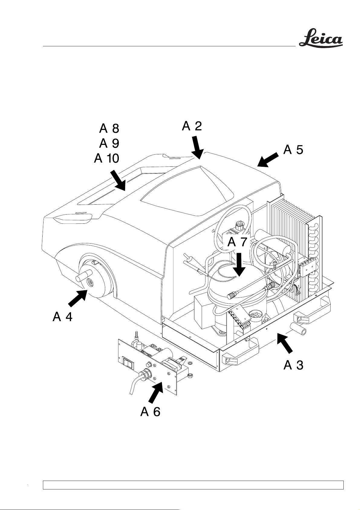
A 1 Overview
A 2 Cover
A 3 Bottom trough
A 4 Hand drive
A 5 Coarse feed
A 6 Electronic rack
A 7 Compressor
A 8 Microtome
A 9 Anti-roll guide
Inhaltsverzeichnis
A 1 Übersicht
A 2 Haube
A 3 Bodenwanne
A 4 Handantrieb
A 5 Grobtrieb
A 6 Elektronikeinschub
A 7 Verdichter
A 8 Mikrotom
A 9 Schnittstrecker
A 10 Knife holder
A 10 Messerhalter
Service Support 03/99 Version 1.0 Table of Contents / Page 1 of 1
Page 11
Leica CM 1100
A 1 Overview / Übersicht
Service Support 03/99 Version 1.0
Fig. / Abb. 230498k1
Page 1 of 1
Page 12
Leica CM 1100
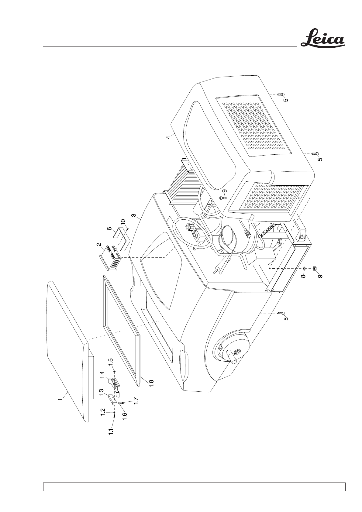
A 2 Cover / Haube
Service Support 03/99 Version 1.0
Fig. / Abb. 120198k1
Page 1 of 3
Page 13
Leica CM 1100
A 2 Cover / Haube
Disassembly of rear cover (4)
1. Remove screws (5) from rear cover (4).
2. Remove nut (9) and washer (8).
3. Take off rear cover (4).
Disassembly of refrigeration control
unit (2)
Disconnect the instrument from the mains
before working on electrical components.
1. Disassemble rear cover (4).
2. Disconnect all cable connections of the
refrigeration control unit (2).
3. Remove screw (10) and take off bracket (6)
towards the rear.
4. Pull refrigeration control unit (2) out towards
the front.
Ausbau Haube hinten (4)
1. Schrauben (5) an der Haube hinten (4)
entfernen.
2. Mutter (9) und Scheibe (8) entfernen.
3. Haube hinten (4) abnehmen.
Ausbau Kühlstellregler (2)
Vor Arbeiten an elektrischen Bauteilen
unbedingt das Gerät vom Netz trennen.
1. Haube hinten (4) ausbauen.
2. Sämtliche Kabelverbindungen des Kühlstellreglers (2) trennen.
3. Schraube (10) entfernen und Bügel (6) nach
hinten abnehmen.
4. Kühlstellregler (2) vorne herausziehen.
Disassembly of front cover (3)
1. Disassemble rear cover (4).
2. Disassemble refrigeration control unit (2).
3. Remove screws (5) from front cover (3).
4. Take off front cover (3).
Disassembly of lever (1.4)
1. Take off lid (1).
2. Remove screws (1.1), washers (1.2) and nuts
(1.5).
3. Remove lever (1.4).
Disassembly of spring steel sheet
(1.3)
1. Take off lid (1).
Ausbau Haube vorne (3)
1. Haube hinten (4) ausbauen.
2. Kühlstellregler (2) ausbauen.
3. Schrauben (5) an der Haube vorne (3) entfernen.
4. Haube vorne (3) abnehmen.
Ausbau Hebel (1.4)
1. Deckel (1) abnehmen.
2. Schrauben (1.1), Scheiben (1.2) und Muttern
(1.5) entfernen.
3. Hebel (1.4) abnehmen.
Ausbau Federblech (1.3)
1. Deckel (1) abnehmen.
2. Disassemble lever (1.4)
3. Remove screws (1.7) and washers (1.6).
4. Take off spring steel sheet (1.3).
Service Support 03/99 Version 1.0
2. Hebel (1.4) ausbauen.
3. Schrauben (1.7) und Scheiben (1.6) entfernen.
4. Federblech (1.3) abnehmen.
Page 2 of 3
Page 14

Leica CM 1100
A 2 Cover / Haube
No. Part Number Qty. Description Remarks Qty.*
1 0469 31140 1 Lid
Deckel
1.1 2101 03205 4 Screw M4 x 6 DIN 912
Schraube M4 x 6 DIN 912
1.2 2171 02114 4 Washer A4.3 DIN 125
Scheibe A4,3 DIN 125
1.3 0469 31577 2 Spring steel sheet
Federblech
1.4 0469 31576 2 Lever
Hebel
1.5 2131 16102 4 Nut M4 DIN 985
Mutter M4 DIN 985
1.6 2171 02121 Washer A3.2 DIN 125
Scheibe A3,2 DIN 125
1.7 2101 03214 4 Screw M3 x 6 DIN 912
Schraube M3 x 6 DIN 912
1.8 0469 31710 1 Sealing frame
Dichtrahmen
2 0469 32120 1 Refrigeration control unit CM1100
Kühlstellregler CM 1100
3 0469 33109 1 Front cover
Haube vorne
4 0469 33110 1 Rear cover
Haube hinten
5 3000 00119 6 Ejot Pt screw K40 x 16 WN 1411
Ejot Pt Schraube K40 x 16 WN 1411
6 0467 30519 1 Bracket
Bügel
7 21020 7117 2 Screw M4 x 10 DIN 85RF
Schraube M4 x 10 DIN 85RF
8 2171 02114 2 Washer A4.3 DIN 125RF
Scheibe A4,3 DIN 125RF
9 2131 46110 2 Nut M4 DIN 934
Mutter M4 DIN 934
10 3000 00123 1 E-Jot Pt screw K30 x 16 WN 14411
E-Jot Pt Schraube K30 x 16 WN 14411
Service Support 03/99 Version 1.0
Page 3 of 3
Page 15
Leica CM 1100
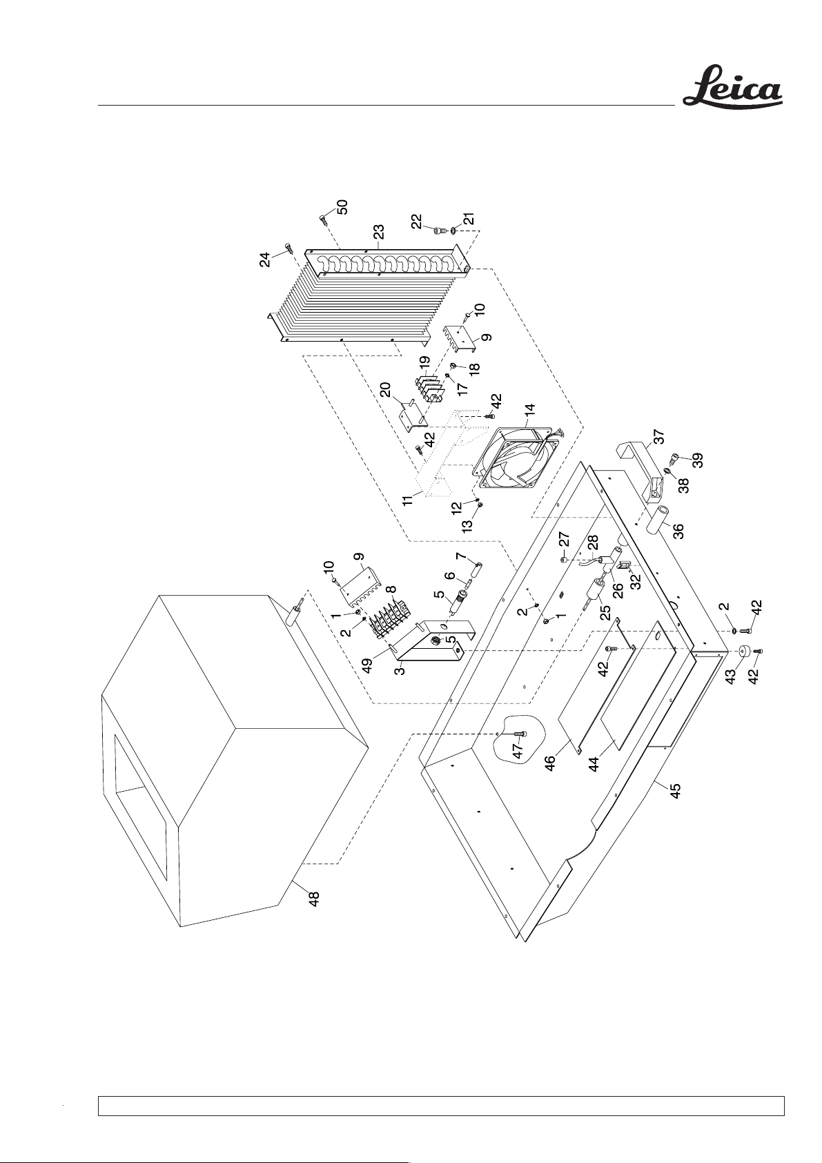
A 3 Bottom trough / Bodenwanne
Service Support 03/99 Version 1.0
Fig. / Abb. 290498k1
Page 1 of 3
Page 16

Leica CM 1100
A 3 Bottom trough / Bodenwanne
No. Part Number Qty. Description Remarks Qty.*
1 2131 45102 8 Nut M4 DIN 934 RF
Mutter M4 DIN 934 RF
2 2171 02114 16 Washer A4.3 DIN 125 RF
Scheibe A4,3 DIN 125 RF
3 0469 31639 1 Bracket
Bügel
5 0356 10703 1 Fuse carrier Type G
Sicherungshalter Typ G
6 6943 04000 1 Fuse 5V 4AT
Sicherung 5V 4AT
7 0356 10704 1 Cover cap FG - SI
Verschlußkappe FG - SI
8 0469 31823 1 Terminal strip JX 2 5-pin Type 3070PC/M
Anschlußleiste JX 2 5-polig Typ 3070PC/M
9 0469 31996 2 Cover cap Type 3070-A2/05
Abdeckkappe Typ 3070-A2/05
10 0469 31995 4 Fastening pins Type BEF-307018
Befestigungsstifte Typ BEF-3070/18
11 0469 31126 1 Fan carrier
Lüfterhalterung
12 2171 02114 4 Washer A4.3 DIN 125 RF
Scheibe A4,3 DIN 125 RF
13 2131 45102 4 Nut M4 DIN 934 RF
Mutter M4 DIN 934 RF
14 0469 31311 1 Fan, 115V and 230V
Lüfter, 115V und 230V
17 2171 02114 2 Washer A4.3 DIN 125 RF
Scheibe A4,3 DIN 125 RF
18 2131 45102 2 Nut M4 DIN 934 RF
Mutter M4 DIN 934 RF
19 0416 25049 1 Terminal JX 3 3-pin
Anschlußklemme JX 3 3-polig
20 0469 31638 1 Angle
Winkel
21 2171 01107 14 Washer A6.4 DIN 125 RF
Scheibe A6,4 DIN 125 RF
22 2101 02238 2 Screw M6 x 8 DIN 912 RF
Schraube M6 x 8 DIN 912 RF
23 0469 31128 1 Condenser
Verflüssiger
Service Support 03/99 Version 1.0
Page 2 of 3
Page 17

Leica CM 1100
A 3 Bottom trough / Bodenwanne
No. Part Number Qty. Description Remarks Qty.*
24 2101 03111 1 Screw M4 x 10 DIN 912 RF
Schraube M4 x 10 DIN 912 RF
25 0398 17539 1 PVC hose
PVC- Schlauch
26 0452 27942 1 T piece
T-Stück
27 0469 31699 1 Cover cap of tubular heater
Rohrheizungsverschlußkappe
28 0469 31286 1 Tubular defrost heater 12V/30W
Rohrabtauheizung 12V/30W
32 6883 00016 1 Cable clip 19.1 x 27.2 x 1.6
Kabelhalter 19,1 x 27,2 x 1,6
36 0469 31939 1 Defrost water drain pipe assy.
Tauwasserabflußrohr, kpl.
37 0115 31131 4 Carrying handle
Bügelgriff
38 2171 01107 8 Washer A6.4 DIN 125 RF
Scheibe A6,4 DIN 125 RF
39 2101 03142 8 Screw M6 x 12 DIN 912 RF
Schraube M6 x 12 DIN 912 RF
42 2101 03111 12 Screw M4 x 10 DIN 912 RF
Schraube M4 x 10 DIN 912 RF
43 0386 21402 4 Foot of housing
Gehäusefuß
44 0469 31924 1 Pertinax plate
Pertinaxplatte
45 0469 30757 1 Bottom trough
Bodenwanne
46 0469 31952 1 Cover for electronics
Elektronikabdeckung
47 3000 00120 4 Spax screw 4 x 30
Spax- Schraube 4 x 30
48 0469 31608 1 Internal container, foamed
Innenbehälter, geschäumt
49 2101 03125 2 Screw M5 x 10 DIN 912 RF
Schraube M5 x 10 DIN 912 RF
50 2101 43127 1 Screw M4 x8 DIN 7985 RF
Schraube M4 x8 DIN 7985 RF
Service Support 03/99 Version 1.0
Page 3 of 3
Page 18
Leica CM 1100
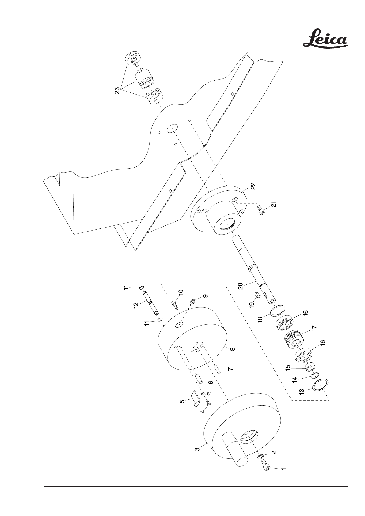
A 4 Hand drive / Handantrieb
Service Support 03/99 Version 1.0
Fig. / Abb. 220498k1
Page 1 of 4
Page 19

Leica CM 1100
A 4 Hand drive / Handantrieb
Disassembly of hand drive
1. Remove screw (1) and washer (2); pull off the
handwheel (3) and flywheel mass (8).
2. Remove screw (10) and pull off flywheel mass
(8).
3. Remove screw (4) and circlips (11), undo
thrust piece (9) and take off sliding bolt (5)
and bolt (12).
4. Loosen the fastening screw of the coupling
(23).
5. Remove circlip (13) and pull out the shaft (20)
assy. to the front.
6. Remove circlip (14) and feather key (19).
7. Remove ring (15), ball bearing (16) as well as
compensating washer (18) from shaft (20).
8. Remove screw (21) and flange (22).
Demontage Handantrieb
1. Schraube (1) und Scheibe (2) entfernen
Handrad (3) und Schwungmasse (8) abziehen.
2. Schraube (10) entfernen und Schwungmasse
(8) abziehen.
3. Schraube (4) und Sicherungsringe (11)
entfernen, Druckstück (9) öffnen und Schieber
(5) und Bolzen (12) abnehmen.
4. Befestigungsschraube der Kupplung (23)
öffnen.
5. Sicherungsring (13) entfernen und Welle (20)
komplett nach vorne herausziehen.
6. Sicherungsring (14) und Paßfeder (19)
entfernen.
7. Ring (15), Kugellager (16) sowie Ausgleichscheibe (18) von der Welle (20) abnehmen.
Assembly of hand drive
1. To reassemble proceed in reverse order.
8. Schraube (21) entfernen und Flansch (22)
abnehmen.
Montage Handantrieb
1. Die Montage erfolgt in umgekehrter Reihenfolge.
Service Support 03/99 Version 1.0
Page 2 of 4
Page 20

Leica CM 1100
A 4 Hand drive / Handantrieb
No. Part Number Qty. Description Remarks Qty.*
0469 31572 1 Hand drive assy.
Handantrieb, kpl.
1 2101 03141 1 Screw
Schraube M6 x 10 DIN 912 RF
2 2171 12110 1 Washer A6.4 DIN 9021 RF
Scheibe A6,4 DIN 9021 RF
3 0469 31367 1 Handwheel with handle
Handrad mit Umlenkgriff
4 2102 63112 1 Screw M3 x 10 DIN 965 RF
Schraube M3 x 10 DIN 965 RF
5 0469 31063 1 Sliding bolt
Schieber
6 2151 03140 1 Straight pin 6m6 x 12 DIN 7 RF
Zylinderstift 6m6 x 12 DIN 7 RF
7 2151 03109 2 Straight pin 4m6 x 20 DIN 7 RF
Zylinderstift 4m6 x 20 DIN 7 RF
8 0469 31060 1 Flywheel mass
Schwungmasse
9 0468 29891 1 Thrust piece M6
Kugeldruckstück M6
10 2101 03226 3 Screw M4 x 14 DIN 912 RF
Schraube M4 x 14 DIN 912 RF
11 2171 21103 2 Circlip 6 x 0.7 DIN 471
Sicherungsring 6 x 0,7 DIN 471
12 0469 31061 1 Bolt
Bolzen
13 2172 32108 1 Circlip 28 x 1.2 DIN 472 RF
Sicherungsring 28 x 1,2 DIN 472 RF
14 2172 21109 1 Circlip 12 x 1 DIN 471 RF
Sicherungsring 12 x 1 DIN 471 RF
15 0469 30859 1 Ring, short
Ring, kurz
16 0110 13188 2 Deep groove ball bearing 6001-Z15
Rillenkugellager 6001-Z15
17 0469 30860 1 Ring, long
Ring, lang
18 3017 00123 1 Compensating washer 21 x 27 x 0.4
Ausgleichsscheibe 21 x 27 x 0,4
Service Support 03/99 Version 1.0
Page 3 of 4
Page 21

Leica CM 1100
A 4 Hand drive / Handantrieb
No. Part Number Qty. Description Remarks Qty.*
19 2174 02111 1 Feather key A4 x 4 x 10 DIN 6885 RF
Paßfeder A4 x 4 x 10 DIN 6885 RF
20 0469 30858 1 Shaft
Welle
21 2101 03125 3 Screw M5 x 10 DIN 912 RF
Schraube M5 x 10 DIN 912 RF
22 0469 30857 1 Flange
Flansch
23 0452 28685 1 Coupling assy.
Kupplung, komplett
Service Support 03/99 Version 1.0
Page 4 of 4
Page 22

Leica CM 1100
A 5 Coarse feed / Grobtrieb
Service Support 03/99 Version 1.0
Fig. / Abb. 210498k1
Page 1 of 3
Page 23

Leica CM 1100
A 5 Coarse feed / Grobtrieb
Disassembly of coarse feed
1. Loosen screw (6) and pull out handwheel (5)
and coarse feed shaft (10).
2. Loosen screw (12) and pull off coarse feed
shaft (10).
3. Remove screw (2), take off bearing block (3)
and press packing ring (1) as well as ball
bearing (4) out of the bearing block.
Coarse feed adjustment
When adjusting the bearing block (3) and
plate (11) make sure that the both parts are
centered in relation to the microtome axis.
Demontage Grobtrieb
1. Schraube (6) öffnen und Handrad (5) sowie
Grobtriebwelle (10) herausziehen.
2. Schraube (12) öffnen und Grobtriebwelle (10)
abziehen.
3. Schraube (2) entfernen, Lagerbock (3)
abnehmen und Dichtring (1) sowie Kugellager
(4) herausdrücken.
Justage Grobtrieb
Bei der Justage des Lagerbocks (3) und
der Dichtplatte (11) darauf achten, daß
beide Teile zentrisch zur Mikrotomachse
justiert werden.
Service Support 03/99 Version 1.0
Page 2 of 3
Page 24

Leica CM 1100
A 5 Coarse feed / Grobtrieb
No. Part Number Qty. Description Remarks Qty.*
0469 31840 1 Coarse feed assy
Grobtrieb, kpl.
1 0111 32419 1 Packing ring 9 x 22 x7
Dichtring 9 x 22 x7
2 2101 03204 2 Screw M5 x 25 DIN 912 RF
Schraube M5 x 25 DIN 912 RF
3 0469 31132 1 Bearing block
Lagerbock
4 0110 31422 1 Deep groove ball bearing 8 x 22 x 7 DIN 608 RF
Rillenkugellager 8 x 22 x 7 DIN 608 RF
5 0469 31429 1 Handwheel with handle
Handrad mit Umlegegriff
6 2101 03175 1 Screw M5 x 12 DIN 912 RF
Schraube M5 x 12 DIN 912 RF
7 0504 31566 1 Coarse feed shaft, left
Welle Grobtrieb, links
0504 31565 1 Coarse feed shaft, right
Welle Grobtrieb, rechts
8 2171 12103 4 Washer 5.3 DIN 9021
Scheibe 5,3 DIN 9021
9 2101 02210 2 Screw M5 x 8 DIN 912 RF
Schraube M5 x 8 DIN 912 RF
10 0504 31097 1 Coarse feed shaft
Grobtriebwelle
11 0469 31739 1 Plate
Dichtplatte
Service Support 03/99 Version 1.0
Page 3 of 3
Page 25

Leica CM 1100
A 6 Electronic rack / Elektronikeinschub
Service Support 03/99 Version 1.0
Fig. / Abb. 020997k1
Page 1 of 4
Page 26

Leica CM 1100
A 6 Electronic rack / Elektronikeinschub
Disassembly of electronic rack (1)
Disconnect the instrument from the mains
before working on electrical components.
1. Remove all screws (23) and washers (24).
2. Pull electronic rack (1) a little to the front
ensuring that none of the cable connections
are damaged.
Disassembly of transformer (4)
1. Disassemble electronic rack (1).
2. Disconnect all cable connections to the
transformer (4).
3. Remove all screws (23), washers (24) and
(25) as well as nut (26).
4. Take off transformer (4).
Ausbau Elektronikeinschub (1)
Vor Arbeiten an elektrischen Bauteilen
unbedingt das Gerät vom Netz trennen!
1. Sämtliche Schrauben (23) und Scheiben (24)
entfernen.
2. Elektronikeinschub (1) ein wenig nach vorne
herausziehen und darauf achten, daß keine
Kabelverbindungen beschädigt werden.
Demontage Trafo (4)
1. Elektronikeinschub (1) ausbauen.
2. Sämtliche Kabelverbindungen zum Trafo (4)
trennen.
3. Schrauben (23), Scheiben (24) und (25),
sowie Mutter (26) entfernen.
4. Trafo (4) abnehmen.
Disassembly of solid state relay (6)
1. Disassemble electronic rack (1).
2. Disconnect all cable connections to the solid
state relay (6).
3. Remove screws (22) and washers (25).
4. Take off solid state relay (6).
Disassembly of rectifier board (14)
1. Disassemble electronic rack (1).
2. Disconnect all cable connections to the
rectifier board (14).
3. Use a screwdriver to press down the securing
devices of the PCB holders (10) and remove
rectifier board (14).
Demontage Halbleiterrelais (6)
1. Elektronikeinschub (1) ausbauen.
2. Sämtliche Kabelverbindungen zum Halbleiterrelais (6) trennen.
3. Schrauben (22) und Scheiben (25) entfernen.
4. Halbleiterrelais (6) abnehmen.
Demontage Gleichrichterplatine (14)
1. Elektronikeinschub (1) ausbauen.
2. Sämtliche Kabelverbindungen zur
Gleichrichterplatine (14) trennen.
3. Mit einem Schraubendreher die Sicherungssperren an den LP-Haltern (10) eindrücken
und Gleichrichterplatine (14) abnehmen.
Service Support 03/99 Version 1.0
Page 2 of 4
Page 27

Leica CM 1100
A 6 Electronic rack / Elektronikeinschub
Disassembly of radio interference
suppression capacitor (2)
1. Disassemble electronic rack (1).
2. Disconnect all cable connections to the radio
interference suppression capacitor (2).
3. Remove cap nut (11) and washer (13).
4. Take off radio interference suppression
capacitor.
Disassembly of automatic circuit
breaker main switch (27)
1. Disassemble electronic rack (1).
2. Disconnect all cable connections to the
automatic circuit breaker main switch (27).
3. Use a screwdriver to press down the securing
devices of the automatic circuit breaker main
switch (27) and remove automatic circuit
breaker main switch (27).
Demontage Funkentstörfilter (2)
1. Elektronikeinschub (1) ausbauen.
2. Sämtliche Kabelverbindungen zum
Funkentstörfilter (2) trennen.
3. Hutmutter (11) und Scheibe (13) entfernen.
4. Funkenstörfilter abnehmen.
Demontage Si-Automat-Schalter (27)
1. Elektronikeinschub (1) ausbauen.
2. Sämtliche Kabelverbindungen zum Si-Automat-Schalter (27) trennen.
3. Mit einem Schraubendreher die Sicherungssperren an dem Si-Automat-Schalter (27)
eindrücken und Si-Automat-Schalter (27)
abnehmen.
Demontage Anschlußleiste (5)
Disassembly of terminal strip (5)
1. Disassemble electronic rack (1).
2. Disconnect all cable connections to the
terminal strip (5).
3. Remove nut (26) and locking washer (25).
4. Remove terminal strip (5) and varistor (28) if
necessary.
Disassembly of trumpet cable joint (9)
1. Disassemble electronic rack (1).
2. Disconnect all cable connections to the
trumpet cable joint (9).
3. Remove nut for cable bushing (8).
4. Take off trumpet cable joint (9).
1. Elektronikeinschub (1) ausbauen.
2. Sämtliche Kabelverbindungen zur Anschlußleiste (5) trennen.
3. Mutter (26) und Scheibe (25) entfernen.
4. Anschlußleiste (5) abnehmen, ggf. Varistor
(28) entfernen.
Demontage Kabelverbindung Trompete (9)
1. Elektronikeinschub (1) ausbauen.
2. Sämtliche Kabelverbindungen zur Kabelverbindung Trompete (9) trennen.
3. Mutter für Kabeldurchführung (8) entfernen.
4. Kabelverbindung Trompete (9) abnehmen.
Service Support 03/99 Version 1.0
Page 3 of 4
Page 28

Leica CM 1100
A 6 Electronic rack / Elektronikeinschub
No. Part Number Qty. Description Remarks Qty.*
0469 31573 1 Electronic rack assy.
Elektronikeinschub, kpl.
1 0469 31305 1 Mounting plate
Montageplatte
2 0416 19741 1 Radio interfer. suppr. capacitor F.M. 126/224
Funk-Entstörfilter F.M. 126/224
4 0469 31337 1 Transformer CM 1100
Trafo CM 1100
5 0469 31369 1 Terminal strip 6-pin
Anschlußleiste 6-polig
6 6832 28913 1 Solid state relay HD 4850
Halbleiterrelais HD 4850
8 0314 29078 1 Nut for cable bushing PG 13.5
Mutter für Kabeldurchführung PG 13,5
9 0314 30750 1 Trumpet cable joint PG 13.5
Kabelverbindung Trompete PG 13,5
10 6886 00020 4 PCB holder
LP- Halter
11 6449 84704 1 Cap nut M8 Form U
Hutmutter M8 Form U
12 2171 93105 1 Tooth lock washer A8.4 DIN 6797
Zahnscheibe A8,4 DIN 6797
13 2171 01109 1 Washer A8:4 DIN 125 RF
Scheibe A8,4 DIN 125 RF
14 0469 31642 1 Rectifier board
Gleichrichterplatine
15 0469 31641 1 Loom of cables CM 1100
Kabelsatz CM1100
22 2101 43127 2 Screw M4 x 8 DIN 7985 RF
Schraube M4 x 8 DIN 7985 RF
23 2101 43119 4 Screw M4 x 10 DIN 7985 RF
Schraube M4 x 10 DIN 7985 RF
24 2171 02114 8 Washer A4.3
Scheibe A4,3 DIN 125 RF
25 3017 00129 8 Locking washer S4/A2
Sicherungsscheibe S4/A2
26 2131 45102 6 Nut M4
Mutter M4 DIN 934 RF
27 0188 31997 1 Automatic circuit breaker main switch
Si- Automat- Schalter
28 6150 00002 1 Varistor 275V RMS 1W for 230V units
Varistor 275V RMS 1W für 230V Geräte
6150 00001 1 Varistor 130V RMS 0.6W for 100V and 120V units
Varistor 130V RMS 0,6W für 100V und 120V Geräte
Service Support 03/99 Version 1.0
Page 4 of 4
Page 29

Leica CM 1100
A 7 Compressor / Verdichter
Service Support 03/99 Version 1.0
Fig. / Abb. 280498k1
Page 1 of 3
Page 30

Leica CM 1100
A 7 Verdichter
No. Part Number Qty. Description Remarks Qty.*
1 0469 31800 1 Suction pressure pipe WT
Saugdruckleitung WT
2 0469 32154 4 Rubber feet, reinforced for 120V/230V units
Gummifüße, verstärkt für 120V/230V Geräte
3 0469 32715 1 Startup capacitor, 160V/150µF for 100V units
Startkondensator, 160V/150µF für 100V Geräte
4 0469 32716 Operating capacitor, 230V/20µF for 100V units
Betriebskondensator, 230V/20µF für 100V Geräte
0435 31965 Startup capacitor 9517 for 230V units
Startkondensator 9517 für 230V Geräte
0435 30732 Startup capacitor 9440 for 100V units
Startkondensator 9440 für 100V Geräte
5 0443 28764 1 Compressor, FG 75 HAK Embraco 230V/50Hz
Kompressor, FG 75 HAK Embraco 230V/50Hz
0443 28754 1 Compressor, FF 7.5 HBK Embraco 120V/60Hz
Kompressor, FF 7,5 HBK Embraco 120V/60Hz
0469 31970 1 Compressor, FL 1888 H6 100V/50-60Hz
Kompressor, FL 1888 H6 100V/50-60Hz
5.1 2101 02197 4 Screw M6 x 35 DIN 912 RF
Schraube M6 x 35 DIN 912 RF
5.2 2171 12110 4 Screw A6.4 DIN 9021 RF
Scheibe A6,4 DIN 9021 RF
6 0469 31308 1 Capillary tube assy.
Kapillarrohr, komplett
7 0416 25280 1 Filler neck
Füllstutzen
8 0469 31290 1 Solenoid valve assy., VAA air pipe
Magnetventil, komplett, VAA Lüftrohr
9 0469 31291 1 Condenser outlet
Verflüssigerausgang
10 0435 26895 1 Filter drier
Filtertrockner
11 3025 00056 1 Pipe clamp, ø34.3mm for 100V units
Rohrschelle, ø34,3mm für 100V Geräte
12 3025 00057 1 Pipe clamp, ø37.5mm for 100V units
Rohrschelle, ø37,5mm für 100V Geräte
Service Support 03/99 Version 1.0
Page 2 of 3
Page 31

Leica CM 1100
A 7 Verdichter
No. Part Number Qty. Description Remarks Qty.*
13 0435 30733 1 Startup relay 1351031 for 120V units
Compressor FF 7.5 HBK
Anlaufrelais 1351031, für 120V Geräte,
Kompressor FF 7,5 HBK
0435 31966 1 Startup relay 1350380 for 230V units
Compressor FR 75 HAK
Anlaufrelais 1350380, für 230V Geräte,
Kompressor FR 75 HAK
0469 32717 1 Startup relay P6ROG for 100V units
Compressor FL 1888 H6
Anlaufrelais P6R0G, für 100V Geräte,
Kompressor FL 1888 H6
0469 32718 1 for 100V units
Compressor FL 1888 H6
Klixon 6.3C 366C1, für 100V Geräte,
Kompressor FL 1888 H6
14 0800 31963 1 Startup kit for 230V units
Compressor FR 75 HAK
Start up Kit, für 230V Geräte,
Kompressor FR 75 HAK
0800 31943 1 Startup kit for 120V units
Compressor FF 7.5 HBK
Start up Kit, für 120V Geräte,
Kompressor FF 7,5 HBK
0800 32714 1 Startup kit for 100V units
Compressor FL 1888 H6
Start up Kit, für 100V Geräte,
Kompressor FL 1888 H6
15 0469 31126 1 Fan holding device
Lüfterhalterung
16 2101 03111 12 Screw M4 x 10 DIN 912 RF
Schraube M4 x 10 DIN 912 RF
17 2171 02114 4 Screw A4.3 DIN 125 RF
Scheibe A4,3 DIN 125 RF
18 2131 45102 4 Nut M4 DIN 934 RF
Mutter M4 DIN 934 RF
19 2101 03111 1 Screw M4 x 10 DIN 912 RF
Schraube M4 x 10 DIN 912 RF
20 0469 31128 1 Condenser
Verflüssiger
21 2171 01101 14 Washer A6.4 DIN 125 RF
Scheibe A6,4 DIN 125 RF
22 2101 02238 2 Screw M6 x 8 DIN 912 RF
Schraube M6 x 8 DIN 912 RF
Service Support 03/99 Version 1.0
Page 3 of 3
Page 32

Leica CM 1100
A 8 Microtome / Mikrotom
Service Support 03/99 Version 1.0
Fig. / Abb. 220798k1
Page 1 of 4
Page 33

Leica CM 1100
A 8 Microtome / Mikrotom
Disassembly of microtome and
mounting plate
1. Take off lid (15).
2. Take the freezing stage assy. (20) out to-
wards the front through the window in the
housing.
3. see A 5.
Loosen screw (6) and pull out the coarse feed
shaft assy. (10) as well as the handwheel (5).
4. Remove screws (13) on the right and left side
of the mounting plate (12).
5. Push the microtome together with the mount-
ing plate (12) to the left until the coupling (16)
disengages.
6. Take the microtome out towards the front
through the window in the housing.
Ausbau Mikrotom mit Montageplatte
1. Deckel (15) abnehmen.
2. Aufblockstation, kpl. (20) nach vorne durch
die Gehäuseöffnung herausnehmen.
3. siehe A 5
Schraube (6) lösen und die komplette Grobtriebwelle (10) sowie Handrad (5) herausziehen.
4. Schrauben (13) auf der rechten und linken
Seite der Montageplatte (12) entfernen.
5. Mikrotom mit Montageplatte (12) nach links
schieben bis Kupplung (16) nicht mehr greift.
6. Mikrotom nach vorne durch die Gehäuseöffnung herausnehmen.
Einbau Mikrotom mit Montageplatte
Assembly of microtome and mounting
plate
1. To reassemble proceed in reverse order.
2. Specimen arm (17) and handle of the handwheel have to be placed in 12 o'clock position
when reconnecting the coupling parts (16).
3. See A 5.
Bring coarse feed shaft (10) together with
handwheel (19) in position and fix with screw
(6).
1. Der Einbau erfolgt in umgekehrter Reihenfolge.
2. Beim Verbinden der Kupplungsteile (16)
müssen der Objektarm (17) sowie der Griff
des Handrades (18) in oberer Position stehen.
3. Siehe A 5
Grobtriebwelle (10) mit Handrad (19) an
Position bringen und mit Schraube (6) befestigen.
Service Support 03/99 Version 1.0
Page 2 of 4
Page 34

Leica CM 1100
A 8 Microtome / Mikrotom
No. Part Number Qty. Description Remarks Qty.*
1 0504 31117 1 Slot protection bellow
Faltenbelag
2 0504 31116 1 Microtome housing
Gehäuse Mikrotom
3 0504 31269 1 Knob with engraving
Knopf mit Gravur
4 2101 43131 4 Screw M5 x 8 DIN 7985 RF
Schraube M5 x 8 DIN 7985 RF
5 0504 31959 1 Plastic angle
Kunststoffwinkel
6 2152 23105 2 Grooved drive stud 3 x 5 DIN 1476
Kerbnagel 3 x 5 DIN 1476
7 0504 31798 1 Knurled nut
Rändelmutter
8 2121 33124 1 Setscrew M4 x 20 DIN 913 RF
Gewindestift M4 x 20 DIN 913 RF
9 0452 27975 1 Magnet D10 x 5 Neodym
Magnet D10 x 5 Neodym
10 0500 29704 1 Eccentric bolt, short
Exzenterbolzen, kurz
11 0112 303751 1 Clamping lever
Klemmhebel
12 0504 31279 1 Mounting plate
Montageplatte
13 2101 03175 4 Screw M5 x 12 DIN 912
Schraube M5 x 12 DIN 912
14 2101 77135 4 Screw M5 x 10 DIN 7991 RF
Schraube M5 x 10 DIN 7991 RF
15 0469 31140 1 Lid
Deckel
16 0452 28658 1 Coupling
Kupplung
17 0504 31085 1 Specimen arm
Objektarm
18 0469 31367 1 Handwheel
Handrad
Service Support 03/99 Version 1.0
Page 3 of 4
Page 35

Leica CM 1100
A 8 Microtome / Mikrotom
No. Part Number Qty. Description Remarks Qty.*
19 0469 31429 1 Handwheel with handle
Handrad mit Umlenkgriff
20 0469 31782 1 Freezing stage assy.
Aufblockstation, kpl.
21 0469 31781 1 Freezing stage
Aufblockstation
22 0401 13487 4 Brake spring
Bremsfeder
23 2152 21103 4 Grooved drive stud 2 x 6 DIN 1476 Al
Kerbnagel 2 x 6 DIN 1476 Al
Service Support 03/99 Version 1.0
Page 4 of 4
Page 36

Leica CM 1100
A 9 Anti-roll guide / Schnittstrecker
Service Support 03/99 Version 1.0
Fig. / Abb. 070598k2
Page 1 of 3
Page 37

Leica CM 1100
A 9 Anti-roll guide / Schnittstrecker
Disassembly of anti-roll guide
1. Remove grip (10) and pull out anti-roll plate
(19) upwards.
2. Remove nut (2) and pull out screw (1) upwards.
3. Pull out swivel arm (8) and spring (7).
4. Remove screw (5) and take off bearing block
(3).
5. Straight pin (11) is secured with Loctite 638.
Demontage Schnittstrecker
1. Griff (10) entfernen und Antirollplatte (19)
nach oben herausziehen.
2. Mutter (2) entfernen und Schraube (1) nach
oben herausziehen.
3. Schwenkarm (8) und Feder (7) herausziehen.
4. Schraube (5) entfernen und Lagerbock (3)
abnehmen.
5. Stift (11) ist mit Loctite 638 gesichert.
Service Support 03/99 Version 1.0
Page 2 of 3
Page 38

Leica CM 1100
A 9 Anti-roll guide / Schnittstrecker
No. Part Number Qty. Description Remarks Qty.*
0504 31957 1 Anti-roll guide assy.
Schnittstecker, kpl.
1 2101 12111 1 Screw M4 x 20 DIN 6912 VZ
Schraube M4 x 20 DIN 6912 VZ
2 2131 45102 1 Nut M4 DIN 934 RF
Mutter M4 DIN 934 RF
3 0419 30395 1 Bearing block
Lagerbock
4 2151 03149 1 Straight pin 3h11 x 8 DIN 7 RF
Zylinderstift 3h11 x 8 DIN 7 RF
5 2101 13133 1 Screw M4 x 10 DIN 6912 RF
Schraube M4 x 10 DIN 6912 RF
6 3025 00005 1 Cap SW3
Ribekappe SW3
7 0122 30401 1 Compression spring VD-096
Druckfeder VD-096
8 0504 31958 1 Swivel arm
Schwenkarm
10 0419 19445 1 Grip
Griff
11 2151 01127 1 Straight pin 4m6 x 25 DIN 7 VZ
Zylinderstift 4m6 x 25 DIN 7 VZ
12 3025 00022 1 Cap 03.8/10PVCSCHW
Übersteckkappe 03,8/10PVCSCHW
13 0504 32585 1 Axle
Achse
19 0504 32597 1 Glass anti-roll plate, 80mm consisting of items 10,
13, 14, 15, 16, 17 and 18
Antirollplatte, Glas, 80mm, kpl. besteht aus Pos. 10,
13, 14, 15, 16, 17 und 18
Service Support 03/99 Version 1.0
Page 3 of 3
Page 39

Leica CM 1100
A 10 Knife holder / Messerhalter
Service Support 03/99 Version 1.0
Fig. / Abb. 130598k1
Page 1 of 4
Page 40

Leica CM 1100
A 10 Knife holder / Messerhalter
Disassembly of knife holder CE assy.
low and high profile version
1. Turn clamping lever (13) and pull out to the
right. Cap (12) is mounted in place and fixed
with high-speed adhesive.
2. Remove pressure plate 26° (1).
3. The screws (5) are secured with Loctite
274.
Remove screws (5), spacer (2), tension rings
(3), leaf spring (4) and straining rings (16).
4. Setscrews (6) and (9) are secured with
Loctite 222.
5. Remove screws (11) and take off pressure
plate for low profile blades or pressure blade
for high profile blades (10).
6. Magnet (14) is secured with Loctite 638.
Demontage Messerhalter CE kpl.
Schmalband und Breitband
1. Klemmhebel (13) drehen und nach rechts
herausziehen. Übersteckkappe (12) ist
aufgesteckt und mit Sekundenkleber geklebt.
2. Andruckplatte 26° (1) abnehmen.
3. Schrauben (5) sind mit Loctite 274
gesichert.
Schrauben (5) entfernen, Abstandsschiene
(2), Spannfedern (3), Blattfeder (4) und
Spannscheiben (16) abnehmen.
4. Gewindestifte (6) und (9) sind mit Loctite
222 gesichert.
5. Schrauben (11) entfernen und Andruckplatte,
Schmalband bzw. Breitband (10) abnehmen.
6. Magnet (14) ist mit Loctite 638 gesichert.
Service Support 03/99 Version 1.0
Page 2 of 4
Page 41

Leica CM 1100
A 10 Knife holder / Messerhalter
Pressure plate and clearance angle
adjustment
1. Bring pressure plate (10) in correct position
and lightly tighten screws (11).
2. Reposition pressure plate (10) in a way that
the contact surface of pressure plate (10) is
adjusted parallel; tighten screws (11).
3. Bring pressure plate (1) in correct position
and fix with clamping lever (13).
4. Only lightly clamp pressure plate (1). Pressure plate (1) is adjusted in height with the
screws (9). The upper edges of the pressure
plates (10) and (1) must be at the same
height and parallel to each other.
5. The clearance angle of pressure plate (1) is
adjusted with screw (6) so that pressure is
exerted only by the upper edge of pressure
plate (1). A gap of 0.01 - 0.05mm should be
measurable. When adjusting, make sure that
the gap width between the two pressure
plates (10) and (1) is approx. 0.4 - 0.8mm
when the clamping lever is in the opened
position. If this is not the case, bend the leaf
spring (4) until the required gap width is
achieved.
Justage Andruckplatte und Freiwinkel
1. Andruckplatte (10) in Position bringen und
Schrauben (11) leicht anlegen.
2. Andruckplatte (10) so verschieben, daß die
Anlagefläche der Andruckplatte (10) parallel
justiert ist, und dann die Schrauben (11)
festziehen.
3. Andruckplatte (1) in Position bringen und mit
Klemmhebel (13) fixieren.
4. Andruckplatte (1) nur leicht klemmen. Mit den
Schrauben (9) wird die Höhe der Andruckplatte (1) justiert. Die beiden oberen
Kanten der Andruckplatten (10) und (1)
müssen gleich hoch und parallel zueinander
sein.
5. Mit der Schraube (6) wird der Freiwinkel der
Andruckplatte (1) so justiert, daß nur die
obere Kante der Andruckplatte (1) drückt. Es
muß hier ein Spalt von 0,01 - 0,05mm meßbar sein. Bei der Justierung ist darauf zu
achten, daß der Spalt zwischen den beiden
Andruckplatten (10) und (1) im geöffneten
Zustand ca. 0,4 - 0,8mm beträgt. Wird das
Maß nicht erreicht, ist die Blattfeder (4) zu
biegen, bis das Maß erreicht ist.
Fig. / Abb. 180299k1
Service Support 03/99 Version 1.0
Page 3 of 4
Fig. / Abb. 180299k1
Page 3 of 4
Page 42

Leica CM 1100
A 10 Knife holder / Messerhalter
No. Part Number Qty. Description Remarks Qty.*
0504 31947 1 Knife holder CE, high profile
Messerhalter CE Breitband, kpl.
0504 31804 1 Knife holder CE, low profile
Messerhalter CE Schmalband, kpl.
1 0419 30389 1 Pressure plate 26°, coated
Andruckplatte 26°, beschichtet
2 0502 29556 1 Spacer
Abstandsschiene
3 0502 29555 2 Tension spring
Spannfeder
4 0502 29557 1 Leaf spring
Blattfeder
5 2101 13108 2 Screw M4 x 12 DIN 6912 RF
Schraube M4 x 12 DIN 6912 RF
6 2121 73100 1 Setscrew M4 x 4 x 2 DIN 926 RF
Gewindestift M4 x 4 x 2 DIN 926 RF
7 0419 30387 1 Dove-tail guide
Schwalbenschwanzführung
8 2101 13133 4 Screw M4 x 10 DIN 6912 RF
Schraube M4 x 10 DIN 6912 RF
9 2121 33115 2 Setscrew M4 x 5 DIN 913 RF
Gewindestift M4 x 5 DIN 913 RF
10 0504 31805 1 Pressure plate 22°S for low profile blades only
Andruckplatte 22°S nur für Schmalband
0504 31948 1 Pressure plate 22°B for high profile blades only
Andruckplatte 22°B nur für Breitband
11 2101 13143 4 Screw M5 x 8 DIN 9612 R
Schraube M5 x 8 DIN 9612 RF
12 3025 00045 1 Cap D6/30bk
Übersteckkappe D6/30sw
13 0502 29554 1 Clamping lever
Klemmhebel
14 0504 27975 1 Magnet
Magnet
15 0419 30385 1 CE insert
Einsatz CE
16 2171 73100 2 Straining ring ø4,3 DIN 6796 RF
Spannscheibe ø4,3 DIN 6796 RF
Service Support 03/99 Version 1.0
Page 4 of 4
Page 43

Leica CM 1100
Table of contents
B 1 Safety instructions
B 2 Technical data
B 3 First use of the instrument
B 4 Wiring diagram
B 5 Layout of cables
B 6 Cable connections
B 6.1 Terminal strip JX2
B 6.2 Terminal strip JX1
B 6.3 Compressor
B 6.4 Rack
B 6.5 Elektronik rack
Refrigeration control unit
Solenoid valve coil
Terminal strip JX3
Fan
Heater 1
Startup capacitor
Temperature sensors
Inhaltsverzeichnis
B 1 Sicherheitsvorschriften
B 2 Technische Daten
B 3 Erstinbetriebnahme
B 4 Schaltplan
B 5 Kabelverlegung
B 6 Kabelanschluß
B 6.1 Anschlußleiste JX2
B 6.2 Anschlußleiste JX1
B 6.3 Verdichter
B 6.4 Einschub
B 6.5 Elektronikeinschub
Regler
Magnetventil- Spule
Anschlußleiste JX3
Ventilator
Heizung 1
Anlaufkondensator
Temperatur Sensoren
B 7 Control unit, parameters and
settings
B 8 Procedural instructions
B 7 Steuereinheit, Parameter und
Einstellungen
B 8 Procedural Instructions
Service Support 03/99 Version 1.0 Table of Contents / Page 1 of 1
Page 44

Leica CM 1100
B 1 Safety instructions / Sicherheitsvorschriften
Transport and installation
• The instrument must be transported in an
upright position only, or at an angle of max.
30 °!
• Do not carry or reposition the instrument by
holding it at parts of the housing or at the
handwheels! Only use the carrying handles
at the front and rear for carrying!
• Prior to transporting the instrument, pull out
the retractable handles of the handwheel
and coarse feed wheel and place them in the
depression provided in the center of the
wheel!
• Do not operate in rooms with explosion
hazard!
• To ensure an adequate cooling capacity, the
instrument must be set up with at least 10 cm
distance from walls and furniture!
• Do not place anything next to the compres-
sor ventilation grids to ensure adequate
ventilation at all times!
Transport und Aufstellung
Das Gerät darf nur waagerecht oder leicht
•
gekippt (max. 30 °) transportiert werden!
• Gerät zum Tragen und Schieben nicht am
Gehäuse oder den Handrädern, sondern
ausschließlich an den Tragegriffen vorne
und hinten anfassen!
• Griffe von Handrad und Grobtriebrad zum
Versenken vor dem Transport nach außen
ziehen und in die Mulde klappen!
• Der Betrieb in explosionsgefährdeten Räu-
men ist nicht gestattet!
• Um eine einwandfreie Funktion zu gewähr-
leisten, ist an allen Seiten ein Mindestabstand von 10 cm zu Wänden und Einrichtungsgegenständen einzuhalten!
• Die Lufteintrittsöffnungen des Verflüssigers
müssen frei bleiben, damit eine ausreichende Belüftung gewährleistet ist!
Connection to mains power
• Please refer to the 'Technical data'!
• The instrument must be connected to a
grounded mains power outlet socket.
• During the start-up of the compressor the
nominal voltage must not drop below the
values specified in the 'Technical data'.
Please note that the compressor requires a
start-up current between 10 and 25 A.
Therefore, the electric circuit at the installation site must be inspected by an electrical
engineer to ensure that it meets the requirements for a smooth operation of the
instrument. A constant adequate power supply to the instrument must be ensured at all
times. Failure to comply with the above
will cause severe damage to the instrument.
Elektrischer Anschluß
• Bitte ‘Technische Daten‘ beachten!
• Das Gerät darf nur an eine geerdete
Netzsteckdose angeschlossen werden!
• Beim Anlauf der Kälteanlage darf die Mindest-
nennspannung nicht unterschritten werden
- siehe ‘Technische Daten‘!
Der Verdichter benötigt dabei einen Anlaufstrom von 10 A bzw. 25 A.
Lassen Sie durch einen Fachmann prüfen,
ob die Elektroinstallation vor Ort die Voraussetzung für einen einwandfreien Betrieb des
Gerätes erfüllt.
Für den einwandfreien Betrieb des Gerätes
muß eine spezifikationsgerechte, gleichbleibende Stromversorgung gewährleistet sein.
Nichtbeachtung führt zu Schäden am Gerät!
Service Support 03/99 Version 1.0
Page 1 of 3
Page 45

Leica CM 1100
B 1 Safety instructions / Sicherheitsvorschriften
• Caution:
240 V units may be operated only with the
step-up transformer supplied with the instrument! Failure to comply with this will
cause severe damage to the instrument!
• After transporting, wait at least 4 hours be-
fore turning the instrument on. This waiting
period is necessary to allow the compressor
oil, which may have been displaced during
transport, to return to its original position.
Failure to comply with this can cause severe
damage to the instrument.
Sectioning
• Take care when handling disposable blades.
The cutting edge is extremely sharp and can
cause severe injury!
• Never leave the knife holder with a blade
mounted lying around!
• Dispose of used blades by inserting them
into the receptacle provided at the bottom of
the disposable blade dispenser!
• Achtung bei 240 V Netzspannung!
Diese Geräte dürfen nur mit dem mitgelieferten Vorschalttrafo betrieben werden! Nichtbeachtung führt zu Schäden am Gerät!
• Bei der Erstinbetriebnahme darf das Gerät
erst nach einer Wartezeit von 4 Stunden in
Betrieb genommen werden!
Das bei eventuell gekipptem Transport verlagerte Verdichteröl muß erst in seine Ausgangslage zurückfließen.
Nichtbeachtung der Wartezeit kann zu
schweren Schäden am Gerät führen!
Schneiden
• Vorsicht beim Umgang mit Einwegklingen.
Die Schneide ist extrem scharf und kann
schwere Verletzungen hervorrufen!
• Lassen Sie den ausgebauten Messerhalter
mit eingesetzter Klinge nicht offen herumliegen!
• Klingen stets in das Aufnahmefach am Bo-
den des Klingendispensers entsorgen!
• Always clamp the specimen before the blade!
• Take care when removing the section - the
cutting edge is exposed!
• Prior to manipulating the knife holder and
specimen, or changing the specimen or
blade, and during breaks, always lock the
handwheel and cover the cutting edge with
the anti-roll guide!
• Avoid extended skin contact with cold parts
of the instrument as this can cause frostbite!
• Spannen Sie stets zuerst das Objekt und
dann die Klinge ein!
• Vorsicht bei der Schnittabnahme! Die Schnei-
de ist nicht abgedeckt!
• Vor jeder Manipulation an Messerhalter und
Objekt sowie vor jedem Objektwechsel und
in den Arbeitspausen muß das Handrad verriegelt und die Schneide mit dem Schnittstrecker abgedeckt werden!
• Längerer Hautkontakt mit kalten Teilen des
Gerätes kann zu Gefrierverbrennungen führen!
Service Support 03/99 Version 1.0
Page 2 of 3
Page 46

Leica CM 1100
B 1 Safety instructions / Sicherheitsvorschriften
Removal of the microtome
• Before removing the microtome, turn the
instrument off with the mains switch!
• Wear appropriate protective gloves to re-
move the cold microtome from the cryochamber! Risk of frost bite!
Or wait until the microtome has reached
room temperature.
• The microtome must be completely dry be-
fore reinstallation. Humidity inside will condense and freeze in the cold cryostat and
thus may cause malfunctions or damage.
Cleaning and disinfection
• Do not use organic solvents or any other
aggressive substances for cleaning and disinfection!
We strongly recommend the use of LEICA
Cryofect disinfectant spray!
Only use alcohol or common disinfectants
based on alcohol!
Ausbau des Mikrotoms
• Vor Ausbau des Mikrotoms Gerät ausschal-
ten!
• Zum Herausnehmen des kalten Mikrotoms
geeignete Schutzhandschuhe tragen!
Verletzungsgefahr durch Gefrierverbrennungen!
• Vor dem Wiedereinbau muß das Mikrotom
vollständig trocken sein.
Feuchtigkeit im Innern würde sonst gefrieren und zu Funktionsstörungen oder Schäden führen!
Reinigung und Desinfektion
• Zu Reinigungs- und Desinfektionszwecken
keine organischen Lösungsmittel oder andere aggressive Substanzen verwenden!
Verwenden Sie ausschließlich die in dieser
Gebrauchsanweisung angegebenen Mittel
wie LEICA Cryofect, Alkohol oder handelsübliche Desinfektionsmittel auf alkoholischer Basis!
• For spray disinfection follow the instruc-
tions for use supplied with the disinfectant!
• Do not use external heaters for drying the
cryochamber. This can cause damage to the
slot cover!
Maintenance
• Only qualified and authorized service per-
sonnel may access the internal components
of the instrument for service and repair.
Fuse replacement
• Only use a fuse of the same specification!
For the required value, please refer to
'Technical data'
label at the rear of the instrument.
or to the fuse specification
• Bei der Sprühdesinfektion beachten Sie bit-
te die mitgelieferte Gebrauchsinfor-mation
des Herstellers!
• Zum Trocknen der Kammer keine Heizgeräte
(Fön, Heizlüfter) einsetzen, da dies den
Faltenbalg beschädigen kann!
Wartung
• Das Gerät darf für Reparatur- und Wartungs-
arbeiten nur von qualifizierten und autorisierten Servicetechnikern geöffnet werden!
Austausch der Sicherungen
• Es darf auf keinen Fall ein anderer als der in
den ‘Technische Daten‘ bzw. auf dem
Sicherungsetikett an der Rückseite des Gerätes angegebene Sicherungstyp eingesetzt
werden!
Service Support 03/99 Version 1.0
Page 3 of 3
Page 47

Leica CM 1100
B 2 Technical data
Operating temperature range: 18 °C to 35 °C
All specifications related to temperature are valid only for an ambient temperature up to 22 °C and
for an air humidity lower than 60%!
Type CM 1100-1 CM 1100-3 CM 1100-11
Nominal voltage 230 V AC ±10% 120 V AC ±10% 100 V AC ±10%
Nominal frequency 50 Hz 60 Hz 50/60 Hz
Power draw
during refrigeration 170 VA 170 VA 170 VA
during defrosting for 10 min. 320 VA 400 VA 650 VA
Maximum start-up current for 5 sec. 10 A
eff.
Protective class I I I
Mains fuse 2-pole, T 10 A 2-pole, T 10 A 2-pole, T 10 A
Pollution degree 2 2 2
Overvoltage installation category II II II
Heat output
during refrigeration 170 J/s 170 J/s 170 J/s
during defrosting for 10 min. 320 J/s 400 J/s 650 J/s
Transformer fuse protection F3 T 4 A T 4 A T 4 A
acc. to DIN-IEC 127-II UL-listed UL-listed
25 A
eff.
25 A
eff.
Refrigeration
Temperature range 0 °C to -30 °C ±10%
at an ambient temperature of 22 °C
and air humidity - 60%
when lid is closed;
adjustable in 1 K increments
Defrosting automatic hot gas defrosting,
defrost time freely programmable; 1 defrost cycle/ 24 h,
manual defrosting
duration: 20 min.
Power draw 226 W 204 W 235 W /269 W
Refrigerating output
1)
193 W 185 W 190 W
Maximum nominal pressure 15 bar 15 bar 15 bar
Safety factor 3 3 3
Refrigerant 170 g ± 5 g R134a * 170 g ± 5 g R134a * 155 g ± 5 g R134a *
Compressor oil 0.4 l alpha 22, Kyodo * 0.4 l alpha 22, Kyodo * 0.4 l alpha 22, Kyodo *
* Refrigerant and compressor oil must be replaced by authorized service personnel!
1)
Rating acc. to ASHRAE: Evaporating temperature -23.3 °C
Liquefier temperature 54.4 °C
Ambient temperature 32.2 °C
Microtome
Type Rotary microtome
Section thickness setting range 0 - 20 µm, continuously adjustable
Division of the scale 2 µm
Horizontal specimen feed 15 mm ± 1 mm
Vertical stroke 46 mm ± 1 mm
Maximum specimen size 36 mm
Cryocabinet
Dimensions (W x D x H) 570 x 780 x 380 mm
Weight (including microtome) 50 kg
Service Support 03/99 Version 1.0
Page 1 of 2
Page 48

Leica CM 1100
B 2 Technische Daten
Betriebstemperaturbereich: 18 °C bis 35 °C
Sämtliche Temperaturangaben beziehen sich auf eine Umgebungstemperatur von 22 °C und
Luftfeuchtigkeit von max. 60%!
Typ CM 1100-1 CM 1100-3 CM 1100-11
Nennspannung 230 V AC ±10% 120 V AC ±10% 100 V AC ±10%
Nennfrequenz 50 Hz 60 Hz 50/60 Hz
Aufnahmeleistung
im Kühlbetrieb 170 VA 170 VA 170 VA
bei Abtauung für 10 Min. 320 VA 400 VA 650 VA
Maximaler Anlaufstrom für 5 Sek. 10 A
eff.
Schutzklasse I I I
Netzsicherung 2-polig T 10 A 2-polig T 10 A 2-polig T 10 A
Verschmutzungsgrad 2 2 2
Überspannungskategorie II II II
Abgegebene Wärmemenge
im Kühlbetrieb 170 J/s 170 J/s 170 J/s
bei Abtauung für 10 Min. 320 J/s 400 J/s 650 J/s
Transformatorabsicherung F3 T 4 A T 4 A T 4 A
nach DIN-IEC 127-II UL-gelistet UL-gelistet
25 A
eff.
25 A
eff.
Kälteanlage
Temperatureinstellbereich 0 °C bis -30 °C ±10%
bei einer Umgebungstemperatur von 22 °C
und Luftfeuchtigkeit von - 60%
bei geschlossenem Deckel;
einstellbar 1-K Schritten
Abtauung automatische Heißgas-Abtauung,
Abtauzeitpunkt frei programmierbar; 1 Abtauzyklus/ 24 h,
manuelle Bedarfsabtauung
Dauer: 20 Min.
Aufnahmeleistung 226 W 204 W 235 W /269 W
Kälteleistung
1)
193 W 185 W 190 W
Maximaler Betriebsdruck 15 bar 15 bar 15 bar
Sicherheitsfaktor 3 3 3
Kältemittel 170 g ± 5 g R134a * 170 g ± 5 g R134a * 155 g ± 5 g R134a *
Verdichteröl 0,4 l alpha 22, Kyodo * 0,4 l alpha 22, Kyodo * 0,4 l alpha 22, Kyodo *
* Austausch von Kältemittel und Verdichteröl nur durch autorisiertes Servicepersonal!
1)
Leistungsangabe gem. ASHRAE: Verdampfungstemperatur -23,3 °C
Verflüssigertemperatur 54,4 °C
Raumtemperatur 32,2 °C
Mikrotom
Typ Rotationsmikrotom
Schnittdickeneinstellbereich 0 - 20 µm, stufenlos
Skalenteilung 2 µm
Horizontaler Objektvorschub 15 mm ± 1 mm
Vertikalhub 46 mm ± 1 mm
Maximale Objektgröße 36 mm
Kryostatgehäuse
Abmessungen (B x T x H) 570 x 780 x 380 mm
Gewicht inkl. Mikrotom 50 kg
Service Support 03/99 Version 1.0
Page 2 of 2
Page 49

Leica CM 1100
B 3 First use of the instrument / Erstinbetriebnahme
Switching on
After transporting, wait at least 4 hours before
turning the instrument on. This waiting period
is necessary to allow the compressor oil, which
may have been displaced during transport, to
return to its original position.Failure to comply with this can cause severe damage to the
instrument.
If transported correctly in a horizontal position,
the instrument can be switched on
immediately!
• Before connecting the instrument to the mains
power, please check if the local mains voltage
complies with the power rating indicated on the
nameplate.
Einschalten des Gerätes
Bei der Erstinbetriebnahme darf das Gerät erst
nach einer Wartezeit von 4 Stunden in Betrieb
genommen werden! Das bei eventuell gekipptem Transport verlagerte Verdichteröl muß erst
in seine Ausgangslage zurückfließen. Nichtbeachtung der Wartezeit kann zu schweren Schäden am Gerät führen!
Bei sachgemäßem waagerechtem Transport ist
das Gerät sofort betriebsbereit!
• Prüfen Sie, ob die Netzspannung und Netz-
frequenz in Ihrem Labor mit den Angaben auf
dem Typenschild des Gerätes übereinstimmen!
• Connect the mains plug to the mains power
outlet at the wall.
The mains switch is located on the right side of the
cryocabinet. In the OFF position it is on 'O‘; in the
ON position it is on 'I‘.
The mains switch also has the function of an
automatic mains fuse.
• Turn the instrument on with the mains switch.
The display of the temperature control unit will
read the actual temperature of the cryochamber.
After turning on, it will take approximately 10
seconds until the compressor starts operating.
• Netzstecker in Netzsteckdose stecken.
Der Netzschalter befindet sich an der rechten
Seitedes Kryostatgehäuses.
Im ausgeschalteten Zustand steht er auf ‘O‘, im
eingeschalteten Zustand steht er auf ‘I‘.
Der Netzschalter ist gleichzeitig ein Sicherungsautomat.
• Gerät mit Netzschalter einschalten.
Das Display des Temperaturreglers zeigt zunächst
die IST-Temperatur der Kammer an.
Nach dem Einschalten über den Netzschalter
dauert es ca. 10 Sekunden, bis der Verdichter
anläuft.
Service Support 03/99 Version 1.0
Page 1 of 6
Page 50

Leica CM 1100
B 3 First use of the instrument / Erstinbetriebnahme
Functions of the control unit
The control unit has a 3-digit display for actual and
set temperature and defrost time, with additional
LEDs for instrument status, and three function keys.
In normal operation, the display indicates the actual
temperature of the cryochamber.
LEDs
LED 1 Illuminates in the cooling mode.
LED 2 Illuminates 10 minutes after the defrost
has been started, and remains on during
the duration of the defrost time.
LED 3 Illuminates during the complete defrost
period.
Funktionen des Reglers
Der Regler besteht aus einem 3stelligen Display für
Ist- und Soll-Temperatur und Abtauzeit mit drei
zusätzlichen LEDs für Gerätestatus und drei Funktionstasten.
Im Normalbetrieb wird im Display die Ist-Temperatur der Kammer angezeigt.
LEDs
LED 1 leuchtet, wenn sich das Gerät im Kühl-
modus befindet.
LED 2 leuchtet 10 Minuten nach Start der Ab-
tauung für die Restdauer der Abtauung
LED 3 leuchtet während des gesamten Abtau-
zeitraums
Function keys
P
To program parameters
To increase the indicated value
To decrease the indicated value
Funktionstasten
P
Zur Programmierung von Parametern
Zum Erhöhen des angezeigten Wertes
Zum Verringern des angezeigten Wertes
Service Support 02/01 Version 1.1
Page 2 of 6
Page 51

Leica CM 1100
B 3 First use of the instrument / Erstinbetriebnahme
Setting user definable parameters
• To access parameter programming, press the
P-button.
Any programming field can be accessed for 30
seconds. After that time the display automatically
resets to actual temperature indication. Parameters
can be modified via the arrow keys.
• To adjust the set temperature, press 'P' and
modify the value via arrow key.
• To set the defrost time, press 'P' again and
modify the value via arrow key.
Einstellen der Parameter
• Zum Aufrufen des Parameterprogrammierung
die ‘P‘-Taste drücken.
Jedes Feld wird 30 Sekunden lang für die Parametereingabe angezeigt. Danach kehrt das Display automatisch zur Anzeige der Ist-Temperatur zurück.
Die Werte können mit den Pfeil-Tasten geändert
werden.
• Zum Einstellen der Soll-Temperatur ‘P‘ drücken
und den angezeigten Wert mit der entsprechenden Pfeil-Taste ändern.
• Zum Einstellen der Abtauzeit ‘P‘ erneut drücken
und den angezeigten Wert mit der entsprechenden Pfeil-Taste ändern.
The first two digits are used for hour indication, the
last digit is used for minute indication. Since there
is just one digit for the minute indication, the shown
value has to be multiplied by ten. The defrost time
can be adjusted in 10 minute steps. Fig. shows
defrosting time set at 23:50 hours.
• To set the real time, press 'P' for hour indication
and modify the value via arrow key. Press 'P'
again for minute indication and modify the value
via arrow key.
• When pressing 'P' once more the display shows
'00'. In this mode the entry of a code number is
required. Since coded parameters are reserved
for service personnel only, press 'P' again to
return to set temperature indication, or wait 30
seconds until the display resets to actual temperature indication.
Die ersten beiden Stellen entsprechen den Stunden, die letzte Stelle dient zur Anzeige der Minuten.
Da für die Minutenanzeige nur eine Stelle zur
Verfügung steht, muß der angezeigte Wert mit
zehn multipliziert werden. Die Abtauzeit kann in 10Minuten-Schritten eingestellt werden. Abb. zeigt
die Einstellung der Abtauzeit auf 23:50 Uhr.
• Zum Einstellen der Uhrzeit ‘P‘ zur Anzeige der
Stunden drücken und den Wert mit den PfeilTasten ändern. ‘P‘ zur Anzeige der Minuten
erneut drücken und den Wert mit den PfeilTasten ändern.
• Bei erneutem Drücken von ‘P‘ erscheint im
Display ‘00‘. In diesem Modus muß ein Code
eingegeben werden. Da Code-Parameter ausschließlich dem technischen Kundendienst vorbehalten sind, ‘P‘ erneut drücken, um zur Anzeige der Soll-Temperatur zurückzukehren, oder
30 Sekunden warten, bis das Display zur IstTemperatur-Anzeige zurückkehrt.
Service Support 03/99 Version 1.0
Page 3 of 6
Page 52

Leica CM 1100
B 3 First use of the instrument / Erstinbetriebnahme
Starting and terminating a manual defrost
cycle
• To activate manual defrosting, press 'P' and the
'Arrow-up' key simultaneously. Indication
switches from LED 1 to LED 3.
LED 3 illuminates for 10 minutes until the actual
defrost cycle begins. LED 2 goes on in addition
when defrosting starts.
The overall duration of the defrost cycles is set
to 20 minutes in the factory.
• To deactivate manual defrosting before comple-
tion of a defrost cycle, press 'P' and the 'Arrowup' key simultaneously. LED 2 and LED 3
extinguish, LED 1 is illuminated.
Starten und Beenden der manuellen Bedarfsabtauung
• Zum Aktivieren der manuellen Bedarfsab-
tauung ‘P‘ und die ‘Pfeil auf‘-Taste gleichzeitig drücken. Die Anzeige springt von LED 1
auf LED 3 um.
LED 3 leuchtet 10 Minuten lang, bis der eigentliche Abtauvorgang beginnt. Bei Beginn der
Abtauung leuchtet LED 2 zusätzlich.
Die Gesamtabtaudauer ist ab Werk auf 20 Minuten eingestellt.
• Zum Deaktivieren der manuellen Bedarfsab-
tauung erneut die ‘P‘ und ‘Pfeil auf‘-Taste
gleichzeitig drücken. Die Anzeige springt
von LED 2 und LED 3 auf LED 1 um.
Service Support 03/99 Version 1.0
Page 4 of 6
Page 53

Leica CM 1100
B 3 First use of the instrument
Temperature selection chart (in minus °C)
Tissue 10 - 15 15 - 25 25 - 30
Adrenals
Bone marrow
Brain
Bladder
Breast- fatty
Breast - little fat
Cartilage
Cervix
Fat
Heart and vessel
Intestine
Kidney
Laryngeal
Lip
Liver
Lung
Lymphoid
Muscular
Nose
Pancreas
Prostate
Ovary
Rectal
Skin with fat
Skin without fat
Spleen or bloody tissue
Testicular
Thyroid
Tongue
Uterus curettings
- Above temperature values are based on long-term experience but are only approximate values.
ii
i
i
i
i
ii
i
i
i
i
i
ii
i
i
i
i
i
i
i
i
i
i
ii
ii
i
i
i
i
i
i
Service Support 03/99 Version 1.0
Page 5 of 6
Page 54

Leica CM 1100
B 3 Erstinbetriebnahme
Temperaturtabelle (in minus °C)
Gewebetyp 10 - 15 15 - 25 25 - 30
Nebenniere
Knochenmark
Hirn
Blase
Brustgewebe, fettreich
Brustgewebe mit weniger Fett
Knorpel
Gebärmutterhals
Fettgewebe
Herz und Gefäße
Eingeweide
Niere
Kehlkopf
Lippe
Leber
Lunge
Lymphknoten
Muskel
Nase
Bauspeicheldrüse
Vorsteherdrüse
Eierstock
Enddarm
Haut mit Fett
Haut ohne Fett
Milz oder blutiges Gewebe
Hoden
Schilddrüse
Zunge
Uterus-Curetage
- Die in dieser Tabelle angegebenen Temperaturen beruhen auf Erfahrung, sind jedoch lediglich als Richtwerte zu verstehen.
ii
i
i
i
i
i
ii
i
i
i
i
i
i
ii
i
i
i
i
i
i
i
i
i
i
i
ii
ii
i
i
i
Service Support 03/99 Version 1.0
Page 6 of 6
Page 55

Leica CM 1100
B 4 Wiring diagram / Schaltplan
Service Support 03/99 Version 1.0
Abb. 290798k2
Page 1 of 2
Page 56

Leica CM 1100
B 4 Wiring diagram / Schaltplan
Service Support 03/99 Version 1.0
Abb. 290798k1
Page 2 of 2
Page 57

Leica CM 1100
B 5 Layout of cables / Kabelverlegung
Service Support 03/99 Version 1.0
Abb. 131097en
Page 1 of 2
Page 58

Leica CM 1100
B 5 Layout of cables / Kabelverlegung
Service Support 03/99 Version 1.0
Abb. 131097k1
Page 2 of 2
Page 59

Leica CM 1100
B 6 Cable connections / Kabelanschluß
B 6.1 Terminal strip JX2 / Anschlußleiste JX2
Service Support 03/99 Version 1.0
Abb. 290798k4
Page 1 of 5
Page 60

Leica CM 1100
B 6 Cable connections / Kabelanschluß
B 6.2 Terminal strip JX1 / Anschlußleiste JX1
Service Support 03/99 Version 1.0
Abb. 290798k5
Page 2 of 5
Page 61

Leica CM 1100
B 6 Cable connections / Kabelanschluß
B 6.3 Compressor / Verdichter
Service Support 03/99 Version 1.0
Abb. 280798k1
Page 3 of 5
Page 62

Leica CM 1100
B 6 Cable connections / Kabelanschluß
B 6.4 Rack / Einschub
Service Support 03/99 Version 1.0
Abb. 290798k3
Page 4 of 5
Page 63

Leica CM 1100
B 6 Cable connections / Kabelanschluß
B 6.5 Electronic rack / Elektronikeinschub
Refrigeration control unit / Regler
Solenoid valve coil / Magnetventil-Spule
Terminal strip JX3 / Anschlußleiste JX3
Fan / Ventilator
Heater 1 / Heizung 1
Startup capacitor
Temperature sensors / Temperatursensoren
Service Support 03/99 Version 1.0
Abb. 280798k2
Page 5 of 5
Page 64

Leica CM 1100
B 7 Control unit, parameters and settings
Programming for service personnel:
After pressing five times P it is possible to enter the code. The input code is 88. The following table shows
the number of the parameters, their settings and the default values. This setting should be not be changed
by unauthorized personnel.
Parameter
No.
actual temperatur - display
nominal value of temp. 0° - -30° -30
defrost time 1 000...235 (1. and 2. digit = hours, 3.
time in hours 0...23 hours Time
time in minutes 0...59 minutes Time
input code 0...99 0
P07 actual value of defrost limiter (t02) display
P08 nominal control value (Hyterese) 0...10K / 0...17F 2
P09 upper set point limit -50°C...50°C / -
P10 lower set point limit 50°C / -57°F to upper limit -30
P11 operating mode 1 = refrigerate
P12 display mode 1 = °Celsiu, 2 = °Fahrenheit 1
P13 correction value control sensor -10K...10K / -17F...17F 0
P14 correction value defrost sensor (t02) -10K...10K / -17F...17F 0
P15 defrost limiting value 0...30°C / 32...65°F 11
P16 defrost mode depends on the choosen operating
P17 defrost time 2 000...235 (1. and2. digit = hours, 3.
P18 defrost time 3 000...235 (1. and digit = hours, 3. digit
P19 defrost time 4 000...235 (1. and digit = hours, 3. digit
P20 duration of defrost cycle 1...99 minutes 20
P21 drip off time after defrost 0...99 minutes 0
P22 warm up time 0 ... 15 minutes 10
P23 upper alarm temperature -50 ... 50°C 50
P24 lower alarm temperature -50 ... P23°C -50
P25 remaining time to completion
off defrost
P26 remaining time to completion
off warm up
P27 normal defrost arrow up = ON
Parameter Settings
digit = minutes
57°F...121°F
2 = deep freeze
3 = heat
mode
digit = minutes)
= minutes)
= minutes)
arrow down = OFF
Default
value
230
0
1
3
OFF
OFF
OFF
display
display
01
Service Support 03/99 Version 1.0
Abb. Tab-1
Page 1 of 1
Page 65

Leica CM 1100
Cab
No.
Measurement
point
should be
Comments
Room Temperature
+23°C
Box Temperature
-30°C
[4]
tv1
> +10°C
...+25°C
meaurem. pos. approx.
10cm in front of
comperessor
[3]
tv2
+35°C ... +40°C
measurement pos. approx.
10cm behind compressor
1
t01 (gilled evaporator)
-37°C ... -39°C
overheating of the
evaporator
2 - 3K
2
t02 (gilled evaporator)
-34°C ... -37°C
Po
-0.40bar
-0.35bar
* 100V/60Hz t01 and t02
2°C cooler
B 8 Procedural Instructions
230V/50Hz * 100V/60Hz
240V/50Hz 120V/60Hz
9
7
1 Lamellenverdampfer Eingang gilled evaporator input
2 Lamellenverdampfer Azsgang gilled evaporator output
3 externes Temperaturmeßgerät external temp. measurement instrument
4 externes Temperaturmeßgerät external temp. measurement instrument
5
10
8
6
Service Support 03/99
LEICA CM 1100 Curcuit Diagram Refrigeration System
Abb. 120299k1
Service Support 03/99 Version 1.0
3
Compressor Fan Capillary tube Gilled Evaporator Hot Gas Regulation
Verdichter Ventilator Kapillarrohr Lamellenverdampfer Heißgasdrossel
1
4
Condenser Filter Drier Tank Evaporator Magnetventil Accumulator
Verflüssiger Sammeltrockner Wandverdampfer Solenold Valve Flüssigkeitsabscheider
2
Page 1 of 3
Page 66

Leica CM 1100
B 8 Procedural Instructions
CM 1100 Boxtemperatur
im V erhältnis zur Raumtemperatur
Service Support 03/99 Version 1.0
Raumtemperatur in°C
Boxtemperatur in°C
Abb. A8-1
Page 2 of 3
Page 67

Leica CM 1100
B 8 Procedural Instructions
im V erhältnis zur Raumtemperatur
CM 1100 Verdampfungstemperatur
Service Support 03/99 Version 1.0
Raumtemperatur in°C
V erdampfungstemperatur in°C
Abb. A8-2
Page 3 of 3
Page 68

Short Information Acrobat Reader / Kurzinformation Acrobat Reader
Last page
Letzte Seite
Next page
Nächste Seite
Previous page
Vorherige Seite
First page
Erste Seite
Show / hide navigation window
Navigationsfenster anzeigen / ausblenden
Print
Drucken
Save
Speichern
Open web site
Webseite öffnen
Open
Öffnen
Search results
Suchergebnisse
Search set of documents
Dokumentensatz durchsuchen
Search
Suchen
Width of window
Fensterbreite
Whole page
Ganze Seite
Original size
Originalgröße
Go to next view
Gehe zu nächster Ansicht
Go to previous view
Gehe zu vorheriger Ansicht
 Loading...