

Page 1
Leica CM1100
Cryostat
Instructions for use
Leica CM1100 V1.3 RevB English – 09/2012
Order-No.: 14 0469 80101, RevB
Always keep this manual near the instrument!
Read carefully prior to operating the instrument!
Page 2

Page 3

1. Important information
Serial No. .....................................................................
Year of manufacture: .................................................
Manufactured: ........ Federal Republic of Germany
Until the ratification of the guideline for in-vitro diagnostic instruments this product is categorized
according to the MedGV (National Regulations for
Medical Appliances) as a Class 3 equipment.
The information, numerical data, notes and value judgments contained in this manual represent the current
state of scientific knowledge and state-of-the-art technology as we understand it following thorough investigation in this field. We are under no obligation to update the present manual periodically and on an ongoing basis according to the latest technical developments, nor to provide our customers with additional
copies, updates etc. of this manual.
For erroneous statements, drawings, technical illustrations etc. contained in this manual we exclude liability as far as permissible according to the national
legal system applicable in each individual case. In particular, no liability whatsoever is accepted for any financial loss or consequential damage caused by or
related to compliance with statements or other information in this manual.
Statements, drawings, illustrations and other information as regards contents or technical details of the
present manual are not to be considered as warranted
characteristics of our products. These are determined
only by the contract provisions agreed between ourselves and our customers.
Leica Biosystems Nussloch GmbH
Heidelberger Str. 17-19
D-69226 Nussloch
Germany
Telephone: 062 24 /1 43-0
Telefax: 0 62 24/143-2 68
web: http://www.LeicaBiosystems.com
Leica reserves the right to change technical specifications as well as manufacturing processes without
prior notice. Only in this way is it possible to continuously improve the technology and manufacturing techniques used in our products.
This document is protected under copyright laws. Any
copyrights of this document are retained by Leica
Biosystems Nussloch GmbH.
Any reproduction of text and illustrations (or of any
parts thereof) by means of print, photocopy, microfiche,
web cam or other methods – including any electronic
systems and media – requires express prior permission in writing by Leica Biosystems Nussloch GmbH.
For the instrument serial number and year of manufacture, please refer to the name plate at the back of
the instrument.
© Leica Biosystems Nussloch GmbH
Leica CM1100 – Cryostat
3
Page 4

2. Table of contents
1. Important information ....................................................................................................................................................3
2. Table of contents ............................................................................................................................................................ 4
3. Safety instructions for handling the instrument........................................................................................................5
3.1 Safety features ............................................................................................................................................................................................ 5
3.1.1 Locking the handwheel .............................................................................................................................................................................. 5
3.1.2 Knife guard ................................................................................................................................................................................................... 5
3.2 General hazards .......................................................................................................................................................................................... 5
4. Technical data ................................................................................................................................................................ 8
5. General description .......................................................................................................................................................9
5.1 Leica CM 1100 Overview ............................................................................................................................................................................ 9
5.2 Product description .................................................................................................................................................................................. 10
5.3 Standard delivery range........................................................................................................................................................................... 10
6. Unpacking and installation .................................................................................................................................... 11
6.1 Unpacking................................................................................................................................................................................................... 11
6.2 Site requirements ..................................................................................................................................................................................... 12
6.3 Transport to the installation site ............................................................................................................................................................. 12
7. First use of the instrument ....................................................................................................................................... 13
7.1 Connection to mains power .................................................................................................................................................................... 13
7.2 Installing the accessories........................................................................................................................................................................ 13
7.3 Switching on .............................................................................................................................................................................................. 14
7.4 Functions of the control unit ................................................................................................................................................................... 14
7.4.1 LEDs ............................................................................................................................................................................................................. 14
7.4.2 Function keys ............................................................................................................................................................................................. 14
7.4.3 Setting user definable parameters ........................................................................................................................................................ 15
7.4.4 Starting and terminating a manual defrost cycle ............................................................................................................................... 15
7.5 Temperature selection chart (in minus °C) .......................................................................................................................................... 16
8. Daily operation ........................................................................................................................................................... 17
8.1 Specimen discs ......................................................................................................................................................................................... 17
8.1.1 Specimen freezing.................................................................................................................................................................................... 17
8.1.2 Fixing the specimen disc in the specimen head ................................................................................................................................. 17
8.2 Knife holder CE .......................................................................................................................................................................................... 18
8.2.1 Changing the rear pressure plate .......................................................................................................................................................... 18
8.2.2 Adjusting the rear pressure plate .......................................................................................................................................................... 18
8.2.3 Adjusting the front pressure plate .......................................................................................................................................................... 19
8.2.4 Inserting the blade .................................................................................................................................................................................... 19
8.2.5 Lateral displacement ................................................................................................................................................................................ 20
8.2.6 Adjusting the anti-roll plate..................................................................................................................................................................... 20
8.2.7 Replacing the glass anti-roll plate......................................................................................................................................................... 21
8.3 Coarse feed wheel.................................................................................................................................................................................... 22
8.4 Trimming .................................................................................................................................................................................................... 22
8.5 Sectioning .................................................................................................................................................................................................. 23
8.6 Section transfer ......................................................................................................................................................................................... 23
8.7 Defrosting ................................................................................................................................................................................................... 24
8.7.1 Programming an automatic defrost cycle ............................................................................................................................................ 24
8.7.2 Starting a manual defrost cycle ............................................................................................................................................................. 24
9. Trouble sh ooting ....................................................................................................................................................... 25
10. Cleaning and disinfection ....................................................................................................................................... 28
10.1 Cleaning...................................................................................................................................................................................................... 28
10.2 Spray disinfection with Leica Cryofect ................................................................................................................................................. 28
10.3 Removal of the microtome ...................................................................................................................................................................... 29
10.4 Reassembly of the microtome ................................................................................................................................................................ 30
11. Maintenance............................................................................................................................................................... 31
11.1 General maintenance............................................................................................................................................................................... 31
11.2 Fuse replacement ..................................................................................................................................................................................... 31
12. Optional accessories ............................................................................................................................................... 32
12.1 Mobile heat extractor............................................................................................................................................................................... 32
12.2 Thermal block............................................................................................................................................................................................ 32
13. Warranty and service ............................................................................................................................................... 33
14. Decontamination Certificate
16. Information for the People´s Republic of China ................................................................................................ 35
(master) ...................................................................................................................... 34
4 Instructions for use V1.3 RevB – 09/2012
Page 5
3. Safety instructions for handling the instrument
3.1 Safety features
The instrument design incorporates the following
safety features: handwheel lock, glass anti-roll guide
of the knife holder CE that has the protective function
of a knife guard.
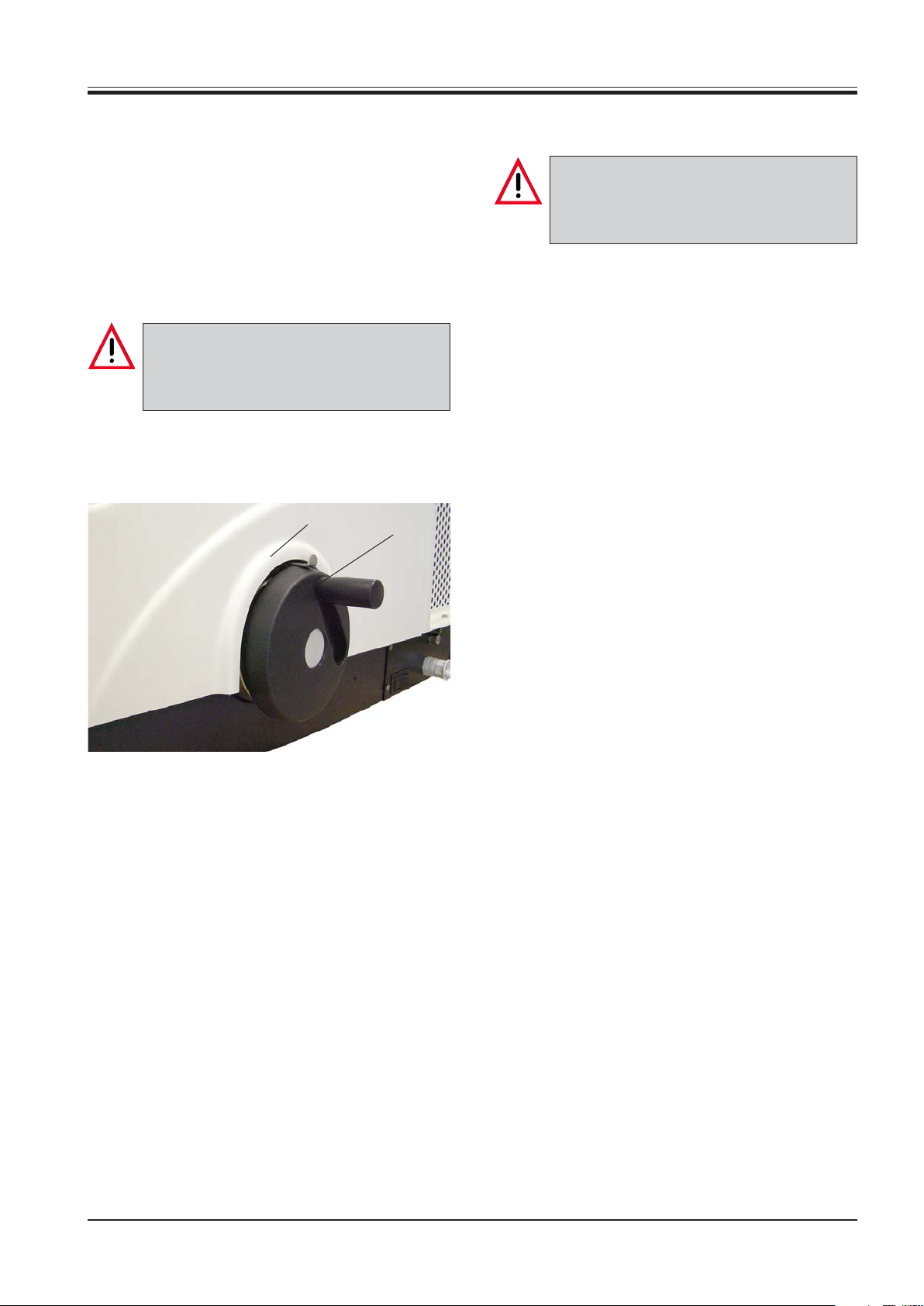
3.1.1 Locking the handwheel
Prior to manipulating the knife holder and
specimen, or changing the specimen or knife,
and during breaks, always lock the
handwheel!
The handwheel can be locked in the upper turning
point.
2
1
3.1.2 Knife guard
Prior to manipulating the knife holder and
specimen, or changing the specimen or knife,
and during breaks, always cover the cutting
edge with the anti-roll guide!
The knife holder CE for disposable blades has a glass
anti-roll guide which is positioned over the knife edge
while sectioning to prevent injury thus acting as a knife
guard.
3.2 General hazards
Despite the safety features provided for operator
safety, the use of the instrument and the applications
for which is designed involve certain risks that cannot
be totally eliminated:
• The handling of disposable blades involves a considerable risk of injury.
Fig. 5.1
• Rotate the handwheel until the handle (1) is positioned in the upper turning point.
• To lock, push the lever (2) towards the housing.
• To unlock, pull the lever (2) away from the housing.
• Extended skin contact with cold parts of the instrument can cause frostbite!
• Sectioning infectious and/or radioactive materials
constitutes a hazard.
Leica CM1100 – Cryostat
5
Page 6

3. Safety instructions for handling the instrument
Transport and installation
• The instrument must be transported in an
upright position only, or at an angle of max.
30 °!
• Do not carry or reposition the instrument
by holding it at parts of the housing or at
the handwheels! Only use the carrying
handles at the front and rear for carrying!
• Prior to transporting the instrument, pull
out the retractable handles of the handwheel and coarse feed wheel and place
them in the depression provided in the
center of the wheel!
• Do not operate in rooms with explosion
hazard!
• To ensure an adequate cooling capacity,
the instrument must be set up with at least
10 cm distance from walls and furniture!
• Do not place anything next to the compressor ventilation grids to ensure adequate
ventilation at all times!
Connection to mains power
• Please refer to the 'Technical data'!
• The instrument must be connected to a
grounded mains power outlet socket.
• During the start-up of the compressor the
nominal voltage must not drop below the
values specified in the 'Technical data'.
Please note that the compressor requires
a start-up current between 10 and 25 A.
Therefore, the electric circuit at the instal-
lation site must be inspected by an electrical engineer to ensure that it meets the
requirements for a smooth operation of the
instrument.
A constant adequate power supply to the
instrument must be ensured at all times.
Failure to comply with the above will
cause severe damage to the instrument.
• Caution:
240 V units may be operated only with the
step-up transformer supplied with the instrument!
Failure to comply with this will cause se-
vere damage to the instrument!
• After transporting, wait at least 4 hours before turning the instrument on.
This waiting period is necessary to allow
the compressor oil, which may have been
displaced during transport, to return to its
original position.
Failure to comply with this can cause severe damage to the instrument.
6 Instructions for use V1.3 RevB – 09/2012
Page 7
3. Safety instructions for handling the instrument
Sectioning
• Take care when handling disposable
blades.
The cutting edge is extremely sharp and
can cause severe injury!
• Never leave the knife holder with a blade
mounted lying around!
• Dispose of used blades by inserting them
into the receptacle provided at the bottom
of the disposable blade dispenser!
• Always clamp the specimen before the
blade!
• Take care when removing the section - the
cutting edge is exposed!
• Prior to manipulating the knife holder and
specimen, or changing the specimen or
blade, and during breaks, always lock the
handwheel and cover the cutting edge
with the anti-roll guide!
Removal of the microtome
• Before removing the microtome, turn the
instrument off with the mains switch!
• Wear appropriate protective gloves to remove the cold microtome from the cryochamber! Risk of frost bite!
Or wait until the microtome has reached
room temperature.
• The microtome must be completely dry before reinstallation. Humidity inside will
condense and freeze in the cold cryostat
and thus may cause malfunctions or damage.
Maintenance
• Only qualified and authorized service personnel may access the internal components of the instrument for service and repair.
• Avoid extended skin contact with cold
parts of the instrument as this can cause
frostbite!
Cleaning and disinfection
• Do not use organic solvents or any other
aggressive substances for cleaning and
disinfection!
We strongly recommend the use of Leica
Cryofect disinfectant spray!
Only use alcohol or common disinfectants
based on alcohol!
• For spray disinfection follow the instructions for use supplied with the disinfectant!
• Do not use external heaters for drying the
cryochamber. This can cause damage to
the slot cover!
Fuse replacement
• Only use a fuse of the same specification!
For the required value, please refer to
Chapter 4. 'Technical data' or to the fuse
specification label at the rear of the instrument.
Leica CM1100 – Cryostat
7
Page 8

4. Technical data
Operating temperature range: 18 °C to 35 °C.
All specifications related to temperature are valid only for an ambient temperature up to 22 °C and for an air
humidity lower than 60%!
Type CM 1100-1 CM 1100-3 CM 1100-11
Nominal voltage 230 V AC ±10% 120 V AC ±10% 100 V AC ±10%
Nominal frequency 50 Hz 60 Hz 50/60 Hz
Power draw
during refrigeration 170 VA 170 VA 170 VA
during defrosting for 10 min. 320 VA 400 VA 650 VA
Maximum start-up current for 5 sec. 10 A
Protective class I I I
eff.
25 A
eff.
Mains fuse 2-pole, T 10 A 2-pole, T 10 A 2-pole, T 10 A
Pollution degree 2 2 2
Overvoltage installation category II II II
Heat output
during refrigeration 170 J/s 170 J/s 170 J/s
during defrosting for 10 min. 320 J/s 400 J/s 650 J/s
Transformer fuse protection F3 T 4 A T 4 A T 4 A
acc. to DIN-IEC 127-II UL-listed UL-listed
25 A
eff.
Refrigeration
Temperature range 0 °C to -30 °C ±10%
at an ambient temperature of 22 °C
_<
and air humidity
60% when lid is closed;
adjustable in 1 K increments
Defrosting automatic hot gas defrosting,
defrost time freely programmable; 1 defrost cycle/ 24 h,
manual defrosting
duration: 20 min.
Power draw 226 W 204 W 235 W /269 W
Refrigerating output
1)
193 W 185 W 190 W
Maximum nominal pressure 15 bar 15 bar 15 bar
Safety factor 3 3 3
Refrigerant 170 g ± 5 g R134a * 170 g ± 5 g R134a * 155 g ± 5 g R134a *
Compressor oil 0.4 l alpha 22, Kyodo * 0.4 l alpha 22, Kyodo * 0.4 l alpha 22, Kyodo
* Refrigerant and compressor oil must be replaced by authorized service personnel!
1)
Rating acc. to ASHRAE: Evaporating temperature -23.3 °C
Liquefier temperature 54.4 °C
Ambient temperature 32.2 °C
Microtome
*
Type Rotary microtome
Section thickness setting range 0 - 20 μm, continuously adjustable
Division of the scale 2 μm
Horizontal specimen feed 15 mm ± 1 mm
Vertical stroke 46 mm ± 1 mm
Maximum specimen size 36 mm
Cryocabinet
Dimensions (W x D x H) 570 x 780 x 380 mm
Weight (including microtome) 50 kg
8 Instructions for use V1.3 RevB – 09/2012
Page 9
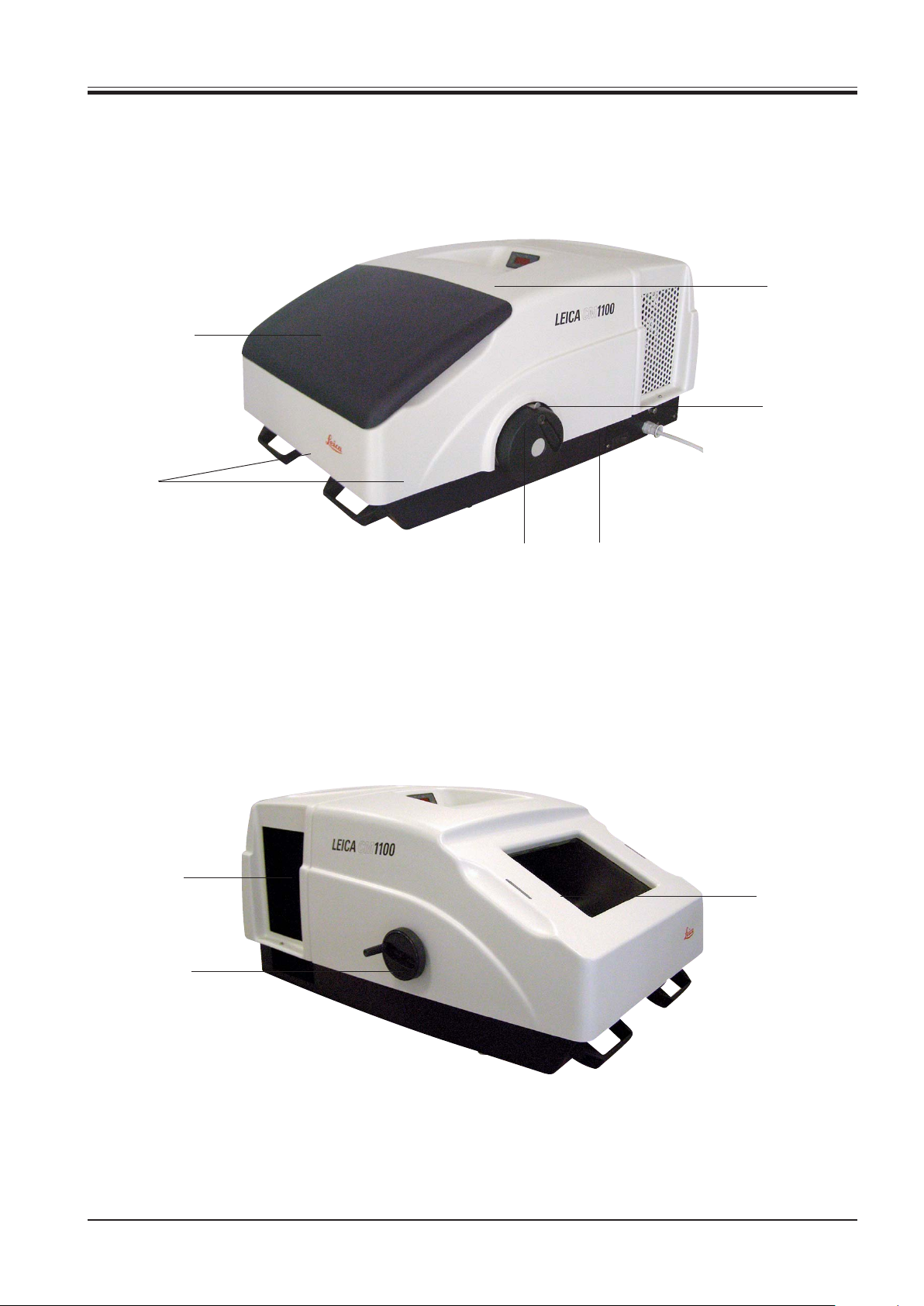
5.1 Leica CM 1100 Overview
Cryochamber
lid
Carrying
handles
5. General description
Control unit
Handwheel
with retractable
countersunk handle
Fig. 9.1
Compressor
ventilation
grids
Coarse feed
wheel with
retractable
countersunk
handle
Lever
for locking the handwheel
Mains switch
Cryochamber
Fig. 9.2
Leica CM1100 – Cryostat
9
Page 10

5. General description
5.2 Product description
The Leica CM1100 is a portable compact cryostat for rapid freezing and manual sectioning of tissue specimens.
Two carrying handles on the front and rear of the housing make it easy for two persons
to transport the instrument. The counterbalanced handwheel is lockable in the top position of the handle.
The corrosion-proof cryochamber is easy to clean and easily accessible after removing the lid. The cryochamber temperature is selectable between 0°C and -30 °C.
The stainless steel rotary microtome is virtually maintenance-free in operation. It is designed for sections in a range of 3μm or 4 μm up to 20μm.
All push button controls and the display are integrated in the control unit.
Important parameters such as set temperature and defrost time can be programmed.
Cryochamber defrosting takes 20 minutes. It is possible to program an automatic de-
frost cycle for a certain time of the day and to activate a manual defrost cycle when required.
5.3 Standard delivery range
Standard delivery includes:
1 Basic instrument
1 Accessory-kit consisting off:
1 Brush, fine .....................................................................................................................................................14 0183 28642
1 Leica-brush ...................................................................................................................................................14 0183 30751
1 Bottle of OCT-compound, mounting medium for cryosectioning, 125ml ............................................ 14 0201 08926
1 Allen key, size 4 ............................................................................................................................................14 0222 04139
1 Bottle of cryostat oil, type 407, 50 ml ......................................................................................................... 14 0336 06098
1 Replacement glass anti roll guide for CE-holder, 70mm wide ..............................................................14 0419 33813
2 Specimen discs, 20mm ............................................................................................................................... 14 0370 08636
1 Section waste tray, large............................................................................................................................ 14 0469 31779
1 Section waste tray, smal ............................................................................................................................ 14 0469 31780
1 Freezing shelf ............................................................................................................................................... 14 0469 31782
1 Knife holder CE for low profile blades ...................................................................................................... 14 0504 33996
1 Pressure plate for high profile blades, 22° ..............................................................................................14 0504 32199
2 Fuses 5x 20 T 4.0A........................................................................................................................................ 14 6943 04000
1 Pair of cut resistant gloves, size S ............................................................................................................ 14 0340 40859
1 Instructions for use "Leica CM1100" -G/E/F/S .................................................................................... 14 0469 80101
10 Instructions for use V1.3 RevB – 09/2012
Page 11
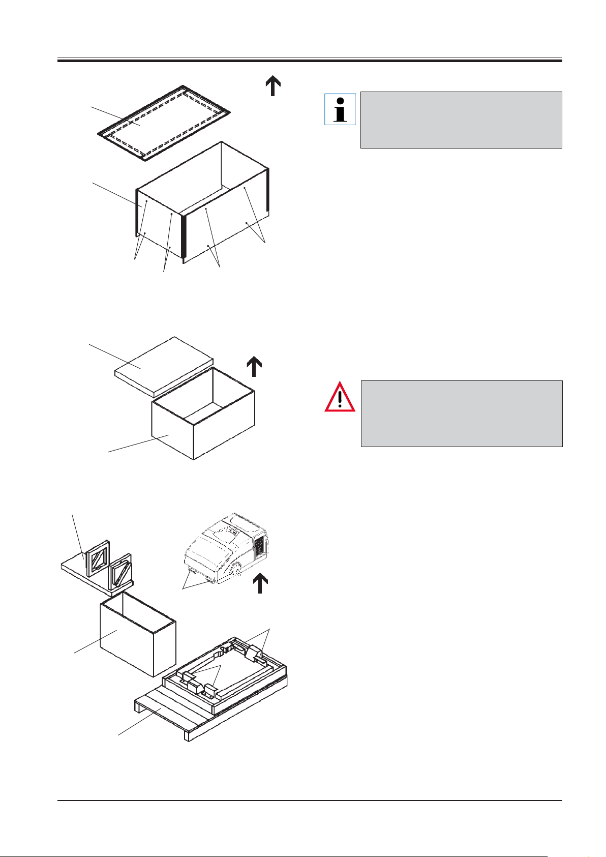
6. Unpacking and installation
6.1 Unpacking
3
Check the transport crate for external damage on arrival of the shipment.
If damages are obvious, please make a complaint to your carrier.
• Remove 2 screws (1) at the top and bottom on all of
2
the four sides of the crate (2).
• Remove the lid (3).
• Lift the body of the crate (2) straight up.
1
1
1
1
• Take the accessory box (4) from the pallet (5).
• Remove the foam plate (6).
• Remove the inner cardboard box (7) by lifting it upwards.
6
• Unscrew the 4 angle brackets (8) by loosening 2
screws each.
Do not carry or reposition the instrument by
holding it at parts of the housing or at the
handwheels!
Only use the carrying handles at the front and
rear for carrying!
7
• Hold the instrument at the carrying handles (9) at
the front and rear and lift it from the pallet.
10
4
Fig. 11
• Take the insert (10) out of the accessory box (4) and
remove all accessories.
9
8
8
5
Leica CM1100 – Cryostat
11
Page 12

6. Unpacking and installation
6.2 Site requirements
Do not operate in rooms with explosion hazard!
To ensure an adequate cooling capacity, the
instrument has to be set up with at least 10
cm distance from walls and furniture.
Do not place anything next to the compressor
ventilation grids to ensure adequate ventilation at all times!
The place of installation must meet the following requirements:
• No direct sunlight,
• Mains power socket at a distance no greater than
the length of the power cord (length approximately
4 meters) - do not use an extension cord,
• No drafts (air condition outlets, etc.) directly over
the instrument,
• Even surface,
• Mainly vibration-free floor,
• Obstruction-free access to the handwheels,
• Room temperature always below 22 °C,
• Air humidity must not exceed 60%.
6.3 Transport to the installation site
The instrument must be transported in an upright position only, or at an angle of max. 30 °!
Do not carry or reposition the instrument by
holding it at parts of the housing or at the
handwheels!
Only use the carrying handles at the front and
rear for carrying!
Prior to transporting the instrument, pull out
the retractable handles of the handwheel and
coarse feed wheel and place them in the depression provided in the center of the wheel!
High room temperatures and excessive air
humidity affect the cooling capacity of the cryostat.
12 Instructions for use V1.3 RevB – 09/2012
Page 13

7. First use of the instrument
7.1 Connection to mains power
Please refer to chapter 4 'Technical data'!
During the start-up of the compressor the
nominal voltage must not drop below the values specified in the 'Technical data'.
Please note that the compressor requires a
start-up current between 10 and 25 A.
Therefore, the electric circuit at the installation site must be inspected by an electrical
engineer to ensure that it meets the requirements for a smooth operation of the instrument.
A constant adequate power supply to the instrument must be ensured at all times.
Failure to comply with the above will cause
severe damage to the instrument.
The instrument must be connected to a
grounded mains power outlet socket.
• The electric circuit at the place of installation has
to be protected separately.
7.2 Installing the accessories
• Remove the lid.
1
2
Fig. 13.1
• To release, turn the clamping lever (1) of the microtome base plate counterclockwise, fully insert the
knife holder (2) on the base plate from the right and
clamp by relocating the lever (1).
5
• Do not connect any other consumers to this electric circuit.
Caution:
240 V units may be operated only with the stepup transformer supplied with the instrument!
Failure to comply with this will cause severe
damage to the instrument!
6
3
4
Fig. 13.2
• Place the section waste tray (3) between the microtome and knife holder from the side.
• Place the section waste tray (4) between the microtome base plate and chamber wall at front.
• Place the quick-freeze shelf (5) over the handwheel
shaft between the microtome and right-hand chamber wall.
• Place the brushes in the location holes (6) of the
quick-freeze shelf.
• Place all tools needed for specimen preparation in
the cryochamber for precooling.
• Replace the lid.
Leica CM1100 – Cryostat
13
Page 14

7. First use of the instrument
7.3 Switching on
After transporting, wait at least 4 hours before turning the instrument on.
This waiting period is necessary to allow the
compressor oil, which may have been displaced during transport, to return to its original position.
Failure to comply with this can cause severe
damage to the instrument.
If transported correctly in a horizontal position, the instrument can be switched on immediately!
• Before connecting the instrument to the mains
power, please check if the local mains voltage complies with the power rating indicated on the nameplate.
7.4 Functions of the control unit
Fig. 14.2
The control unit has a 3-digit display for actual and set
temperature and defrost time, with additional LEDs for
instrument status, and three function keys.
In normal operation, the display indicates the actual
temperature of the cryochamber.
7.4.1 LEDs
LED 1 Illuminates in the cooling mode.
LED 2 Illuminates for 10 minutes before defrosting ac
tually begins.
LED 3 Illuminates while defrosting takes place
Fig. 14.1
• Connect the mains plug to the mains power outlet
at the wall.
The mains switch is located on the right side of the
cryocabinet. In the OFF position it is on 'O‘; in the ON
position it is on 'I‘.
The mains switch also has the function of an automatic
mains fuse.
• Turn the instrument on with the mains switch.
The display of the temperature control unit will read
the actual temperature of the cryochamber.
7.4.2 Function keys
P
To program parameters
To increase the indicated value
To decrease the indicated value
After turning on, it will take approximately 10
seconds until the compressor starts operating.
14 Instructions for use V1.3 RevB – 09/2012
Page 15

7. First use of the instrument
7.4.3 Setting user definable parameters
• To access parameter programming, press the P-
button.
Any programming field can be accessed for 30 seconds. After that time the display automatically resets
to actual temperature indication. Parameters can be
modified via the arrow keys.
• To adjust the set temperature, press 'P' and modify
the value via arrow key.
• To set the defrost time, press 'P' again and modify
the value via arrow key.
7.4.4 Starting and terminating a manual defrost cycle
• To activate manual defrosting, press 'P' and the
'Arrow-up' key simultaneously. Indication switches
from LED 1 to LED 3.
LED 3 illuminates for 10 minutes until the actual defrost cycle begins.
LED 2 goes on in addition when defrosting
starts.
The overall duration of the defrost cycles is
set to 20 minutes in the factory.
• To deactivate manual defrosting before completion
of a defrost cycle, press 'P' and the 'Arrow-up' key
simultaneously. LED 2 and LED 3 extinguish, LED 1
is illuminated.
Fig. 15
The first two digits are used for hour indication, the
last digit is used for minute indication. Since there is
just one digit for the minute indication, the shown value
has to be multiplied by ten. The defrost time can be
adjusted in 10 minute steps. Fig. 15 shows defrosting time set at 23:50 hours.
• To set the real time, press 'P' for hour indication
and modify the value via arrow key. Press 'P' again
for minute indication and modify the value via arrow key.
• When pressing 'P' once more the display shows
'00'. In this mode the entry of a code number is required. Since coded parameters are reserved for
service personnel only, press 'P' again to return to
set temperature indication, or wait 30 seconds until the display resets to actual temperature indication.
Leica CM1100 – Cryostat
15
Page 16

7. First use of the instrument
7.5 Temperature selection chart (in minus °C)
Tissue 10 - 15 15 - 25 25 - 30
Adrenals
Bone marrow
Brain
Bladder
Breast- fatty
Breast - little fat
Cartilage
Cervix
Fat
Heart and vessel
Intestine
Kidney
Laryngeal
Lip
Liver
Lung
❉❉
❉
❉
❉
❉
❉
❉❉
❉
❉
❉
❉
❉
❉
❉❉
❉
❉
Lymphoid
Muscular
Nose
Pancreas
Prostate
Ovary
Rectal
Skin with fat
Skin without fat
Spleen or bloody tissue
Testicular
Thyroid
Tongue
Uterus curettings
❉
❉
❉
❉
❉
❉
❉
❉
❉
❉❉
❉❉
❉
❉
❉
- Above temperature values are based on long-term experience but are only approximate values.
16 Instructions for use V1.3 RevB – 09/2012
Page 17

8. Daily operation
8.1 Specimen discs 8.1.2 Fixing the specimen disc in the specimen head
Always clamp the specimen before the blade!
1
3
• Lock the handwheel.
• Loosen the screw (3) on the specimen head.
Prior to manipulating the knife holder and
specimen, or changing the specimen or blade,
and during breaks, always lock the handwheel and cover the cutting edge with the
anti-roll guide!
2
Fig. 17
Specimen discs (1) are available in different sizes of 20 and 25 mm in diameter. The design of the surface ensures firm contact with the specimen.
8.1.1 Specimen freezing
• Cut the sample to size. The specimen should be no
greater than 2 cm x 2 cm x 2 cm.
• Apply enough cryocompound to a specimen disc
at room temperature.
• Place the specimen on the disc and orient.
• Place the specimen disc with the specimen in one
of the two holes of the quick-freeze shelf (2) and
freeze the specimen.
• Insert the shaft of the specimen disc (1) with the
frozen specimen in the location hole of the specimen head and tighten the screw (3).
Make sure that the shaft of the specimen disc is fully
inserted. The entire rear surface must have a good
contact with the specimen head.
Specimen freezing can be accelerated by additionally using a mobile heat extractor, which
is available as an optional accessory (see
Chapter 12. ‘Optional accessories‘).
• Once the specimen is frozen, fix the specimen disc
in the specimen head and start sectioning.
Leica CM1100 – Cryostat
17
Page 18

8. Daily operation
8.2 Knife holder CE
The knife holder CE is equipped with a pressure plate for low profile blades on delivery.
A pressure plate for high profile blades is supplied separately.
If you wish to use high profile disposable
blades, it is necessary to change the rear pressure plate (see 8.2.1).
After changing, the rear and front pressure
plates need to be readjusted (see 8.2.2 and
8.2.3).
8.2.1 Changing the rear pressure plate
5
8.2.2 Adjusting the rear pressure plate
The rear pressure plate (5) sits on two screws which
permit height an parallel adjustment of the pressure
plate. The two screws can be accessed through corresponding openings on the underside of the knife
holder and can be adjusted with an Allen key, size 2.
• To remove the blade, rotate the clamping lever (2)
forward.
• Carefully remove the blade.
• Remove the clamping lever (2).
4
3
7
2
10
9
Fig. 18.1
10
• Loosen the 4 screws (4) on the back of the knife
holder by using an Allen key size 4.
• Remove the pressure plate (5).
• Fix the new pressure plate with the 4 screws (4).
Tighten the screws only lightly, since the next step
will be to adjust the plate in height and parallelism.
7
5
Fig. 18.2
• Adjust height and parallelism of the pressure plate
(5) such that the bearing surface for the blade is at
a level approximately 0.1 mm higher than the base
of the cheeks of the knife holder.
• Tighten the screws (4).
18 Instructions for use V1.3 RevB – 09/2012
Page 19

Fig. 19.1
8. Daily operation
8.2.4 Inserting the blade
3
Take care when handling disposable blades.
7
5
The cutting edge is extremely sharp and can
cause severe injury!
Never leave the knife holder with a blade
mounted lying around!
Avoid extended skin contact with cold parts
of the instrument as this can cause frostbite!
All components of the cryostat as well as the
knife or blade and the tools for specimen
preparation should be precooled in the cryostat before starting sectioning!
8.2.3 Adjusting the front pressure plate
• Place the pressure plate (7) in its correct position,
insert the clamping lever (2) and slightly fasten the
pressure plate by tightening the clamping lever just
a bit.
The screws (10) on the underside of the knife holder
are used to adjust the height of the pressure plate.
• Adjust the height of the pressure plate (7) with
screws (10). The upper edges of both pressure
plates (5) and (7) have to be at the same height and
parallel to each other.
The clearance angle of the pressure plate (7) is adjusted with screw (9) which can be accessed at a slant
angle from behind, through an opening in the underside of the knife holder.
• Insert the blade with the cutting edge facing downwards in order to minimize the risk of injury and fasten it slightly with clamping lever (2).
3
4
2
Fig. 19.2
• Release the lever (3) by turning it counterclockwise.
• Turn the anti-roll guide (2) to the left.
• Insert the blade (4) carefully either from above or
from the side, so that it fits in between the pressure
plate and the knife support. Make sure that the blade
is in central position.
• Adjust the pressure plate (7) with screw (9) in such
a way that only the upper edge of the pressure plate
actually exerts pressure on the blade. A visible gap
must remain. When the pressure plate is clamped
tightly, this gap will disappear.
Leica CM1100 – Cryostat
• Tighten the lever (3) by turning it clockwise.
• Reposition the anti-roll guide on the blade.
19
Page 20

8. Daily operation
8.2.5 Lateral displacement
If the sectioning results start lacking quality, the knife
holder can be displaced laterally to use another blade
position.
1
Fig. 20.1
Proceed as follows:
• Release the clamping lever (1) by turning it counterclockwise and move the knife holder including
the blade laterally to the desired position.
8.2.6 Adjusting the anti-roll plate
Parallel adjustment of the anti-roll plate and blade
It may be necessary to align the front edge of the antiroll plate parallel to cutting edge of the blade.
7
10
8
9
Fig. 20.2
Proceed as follows:
• Retighten the clamping lever (1) by turning it clockwise
• Loosen screw (10), hold the anti-roll guide at the
grip (8) and align the front edge of glass plate parallel with the cutting edge of the blade.
• Retighten screw (10) after alignment.
20 Instructions for use V1.3 RevB – 09/2012
Page 21

8. Daily operation
• To raise the anti-roll plate (to move it towards the
blade), turn the knurled knob (9, Fig. 20.2) counterclockwise.
• To lower the anti-roll plate (to retract it from the
blade), turn the knurled knob (9, Fig. 20.2) clockwise.
If the anti-roll plate is positioned incorrectly to the blade
edge, problems I and II will occur. Position III shows
the correct position of the anti-roll plate.
IIIIII
Fig. 21.1
8.2.7 Replacing the glass anti-roll plate
3
4
Fig. 21.2
2
6
7
5
• Remove the anti-roll guide from the blade by turning it to the left.
• Unscrew the knurled knob (4).
1
I wrong: anti-roll guide positioned too low
II wrong: anti-roll guide positioned too high
III right: anti-roll guide correctly positioned
In position III the anti-roll plate is correctly adjusted.
It is recommended to first preadjust it at a great section thickness (e.g. 10 μm) and then approach the required section thickness reducing the value in 5 μm
increments and slightly readjust the anti-roll plate in
height with the knurled knob (9, Fig. 20.2).
The glass anti-roll guide is resistant to acetone.
For cleaning the knife holder, domestic detergents can be used.
• Remove the white plastic washer (6) and pull the
anti-roll plate with the shaft up out of the swivel arm.
Install the new anti-roll plate:
• Insert the shaft (2) of the glass anti-roll plate (1) in
the hole of the swivel arm (3) from above ensuring
the pin (6) is located in the notch (7).
• Place the white plastic washer (5) on the shaft (2)
from below.
• Screw the grip (4) on to the shaft (2) from below.
After installation, the anti-roll guide needs to be readjusted as described at 8.2.6.
Leica CM1100 – Cryostat
21
Page 22

8. Daily operation
8.3 Coarse feed wheel
The coarse feed wheel is located on the left side of the
housing. It has a retractable countersunk handle. The
coarse feed wheel always rotates during sectioning
and may therefore not be obstructed.
The coarse feed is used for rapid horizontal movement
of the specimen, both forward and backward.
Clockwise turning moves the sample forward towards
the knife. Counterclockwise turning moves the sample
backward away from the knife.
After having reached the rear or front limit stop respectively, the coarse feed wheel cannot be rotated any
more. Once the front limit stop is reached, no more
specimen advance takes place.
8.4 Trimming
• Remove the anti-roll guide from the cutting edge.
• Unlock the handwheel.
Always observe the specimen while approaching the sample to the blade, to avoid
that the specimen collides with the cutting
edge.
A collision can cause severe damage to both
the blade and specimen!
• Turn the coarse feed wheel clockwise to approach
the specimen to the cutting edge.
• Rotate the handwheel cautiously and check if the
specimen comes in contact with the cutting edge.
• Trim the sample to the desired sectioning plane by
continuously turning the coarse feed wheel and
handwheel.
• Place the anti-roll guide on the blade during trimming and check if it is correctly adjusted.
Fig. 22
The anti-roll guide is correctly adjusted when
the section smoothly slides down between the
anti-roll plate and the blade (see Fig. 21.1)!
• Readjust the anti-roll guide if necessary (see 8.2.6).
22 Instructions for use V1.3 RevB – 09/2012
Page 23

8. Daily operation
8.5 Sectioning
1
Fig. 23
• Select a section thickness with the section thickness control knob (1) at the top of the microtome.
• Decrease the section thickness continually to the
required value.
8.6 Section transfer
Take care when removing the section - the
cutting edge is exposed!
Section transfer to a slide at room temperature
• Carefully approach a slide at room temperature to
the cut section.
The frozen section ‘flies‘ to the slide, rapidly thaws and
thus adheres to the slide surface making subsequent
orientation impossible.
Section transfer to a precooled slide
• Carefully apply the section to the slide by gentle
brushing with a soft brush.
• Orient and flatten the section on the slide surface
with a brush.
After changing from one section thickness to
another, the first two or three sections should
be rejected!
• Make sure the section smoothly slides down between the anti-roll plate and blade.
• Remove the anti-roll guide from the knife for removing and applying a section to a microscope slide.
The section can be transferred either to a precooled
microscope slide or to a microscope slide at room temperature.
• To ensure the section tightly adheres to the slide
surface, warm the cold slide by placing a finger
against the underside of the slide directly underneath the section.
Leica CM1100 – Cryostat
23
Page 24

8. Daily operation
8.7 Defrosting
The Leica CM 1100 provides both programmable automatic and manual defrosting.
During a defrost cycle, whether automatic or manual,
the evaporator is flushed with hot gas to remove frost
that inevitably builds up during routine operation of a
cryostat. Such frost formation on the evaporator can
result in reduced cooling output.
Therefore, the automatic defrost cycle should be pro-
grammed to take place during the night hours to ensure that the operator has the required low temperature and thus good working conditions in the morning.
At installation sites with high air humidity increased
frost formation may occur, and it may become necessary to start a manual defrost cycle in addition, which
can be operated any time when required.
The duration of the defrost cycles is set to 20
minutes in the factory.
The automatic defrost cycle is programmed
for 24.00 hrs in the factory.
A manual defrost cycle can be terminated
earlier.
8.7.1 Programming an automatic defrost cycle
An automatic defrost cycle is programmed by entering the defrost time via the control unit (see 7.4.3).
8.7.2 Starting a manual defrost cycle
A manual defrost cycle is started and terminated via
the control unit (see 7.4.4 ).
Ambient temperatures above 35 °C may cause
defrosting problems.
In this case, a defrost cycle should not be operated as this may cause severe damage to
the instrument.
When switching the instrument off overnight,
the lid should be removed from the cryochamber to prevent condensation water inside.
When the instrument was switched off overnight, a defrost cycle should be started before
resuming normal operation to prevent a loss
in refrigeration output.
After defrosting, cooling is resumed automatically. The
cryochamber will then be cooled to the previously selected set temperature.
During defrosting, the actual chamber temperature is displayed.
When activating a manual defrost cycle the
indication changes from LED 1 to LED 3. LED 3
illuminates for 10 minutes indicating the leadup of the defrost cycle.
When actual defrosting begins LED 2 illuminates in addition.
At the end of the defrost cycle LED 2 and LED 3
extinguish, LED 1 is illuminated.
24 Instructions for use V1.3 RevB – 09/2012
Page 25

Problem Possible causes Remedies
9. Trouble shooting
Frost on chamber walls and microtome
while cryochamber lid not in place
Frost on chamber walls and microtome
while cryochamber lid in place
Sections smear
Sections splinter
Sections not properly flattened
- Cryostat is exposed to air currents
(open windows and doors, air
conditioning).
- Cryochamber was open. This
causes frost formation on the
microtome which is much colder
than the evaporator.
- Frost built up by breathing into the
cryochamber.
- Seal of lid defective.
- Seal of coarse feed shaft defective.
- Seal of handwheel shaft defective.
- Specimen not cold enough.
- Blade and/or anti-roll plate not yet
cold enough and thus cause
sections to thaw.
- Specimen too cold
- Static electricity/air currents.
- Specimen not cold enough.
- Large area specimen.
- Anti-roll plate poorly aligned with
cutting edge.
- Cutting edge blunt or damaged.
- Change place of installation for the
cryostat.
- Replace the lid after terminating
work.
- Select higher set temperature (e.g.
-20 °C instead of -30 °C)
- Inevitable during working.
- Call technical service
- Call technical service
- Call technical service
- Select lower temperature.
- Wait until blade and/or anti-roll
plate have reached chamber
temperature.
- Select higher temperature.
- Remove cause.
- Select lower temperature.
- Trim specimen parallel, increase
section thickness.
- Readjust anti-roll plate.
- Use different part of cutting edge
or replace blade.
Sections not properly flattened despite
correct temperature and correctly
aligned anti-roll plate
Sections curl on anti-roll plate
Scraping noise during sectioning and
specimen return movement
Ridged sections
- Blade and/or anti-roll plate dirty.
- Edge of anti-roll plate damaged.
- Blunt cutting edge.
- Anti-roll plate does not protrude far
enough beyond the cutting edge.
- Anti-roll plate projects too far
beyond the cutting edge and
scrapes on the specimen surface.
- Cutting edge damaged.
- Edge of anti-roll plate damaged.
- Clean with dry cloth or brush.
- Replace plate.
- Use different part of cutting edge,
or replace blade.
- Readjust correctly.
- Readjust correctly.
- Use different part of cutting edge,
or replace blade.
- Replace anti-roll plate.
Leica CM1100 – Cryostat
25
Page 26

9. Trouble shooting
Problem Possible causes Remedies
Chatter during sectioning
Condensation on anti-roll plate and
blade during cleaning
Anti-roll plate damaged after
adjustment
Thick-thin sections
- Specimen insufficiently frozen onto
the specimen disc.
- Specimen disc not clamped tightly.
- Blade not clamped tightly enough.
- Specimen has been sectioned too
thickly and has detached from the
disc.
- Very hard, inhomogeneous specimen.
- Blunt cutting edge.
- Brush, forceps and/or cloth too
warm.
- Plate too high above the cutting
edge. Adjustment was carried out
in direction of the cutting edge.
- Temperature incorrect for the
tissue to be cut.
- Ice buildup on blade back.
- Handwheel speed not uniform.
- Blade not clamped tightly enough.
- Specimen disc not clamped tightly.
- Cryocompound applied to cold
specimen disc; specimen detached
from the disc after freezing.
- Blunt cutting edge.
- Microtome not properly dried
before reinstallation.
- Refreeze specimen onto the disc.
- Check disc clamping.
- Check clamping.
- Refreeze specimen onto the disc.
- Increase section thickness; reduce
specimen surface area if necessary.
- Use different part of cutting edge,
or replace blade.
- Store all tools in the cryochamber.
- Raise plate when aligning.
Be more careful next time.
- Select correct temperature.
Wait until the correct temperature
has been reached.
- Remove ice.
- Adapt speed.
- Check clamping.
- Check clamping.
- Apply cryocompound on warm
disc; mount specimen and freeze.
- Use different part of cutting edge,
or replace blade.
- Dry microtome thoroughly.
Tissue sticks or crumbles on the antiroll plate
26
- Anti-roll plate is too warm or
incorrectly positioned.
- Static electricity.
- Fat on the corner or edge of the
anti-roll plate.
- Rusty blade.
- Cool down anti-roll plate or
reposition plate.
- Remove static electricity.
- Remove fat with alcohol/acetone.
- Remove rust.
Instruction manual, V1.2 – 06/2006
Page 27

Problem Possible causes Remedies
9. Trouble shooting
Flattened sections curl up when antiroll plate is picked up
Sections tear
Inconsistent or insufficient specimen
feed
Specimen disc cannot be removed
Cryostat inoperational; no display
indication
- Static electricity or air currents.
- Anti-roll plate too warm.
- Temperature too low for the tissue
to be cut.
- Blunt part, dirt, dust, frost or rust
on the blade.
- Leading edge of anti-roll plate
damaged.
- Hard particles in the tissue.
- Blade back dirty.
- Microtome was not entirely dry
when switching on refrigeration;
consequently ice built up in the
micrometer feed system.
- Defective microtome.
- Moisture on the underside caused
the disc to freeze to the quickfreeze shelf or specimen head.
- Mains plug not properly connected.
- Overcurrent protection of the
mains switch has responded.
- Fuse defective.
- Remove static electricity.
- Cool down the anti-roll plate.
- Increase temperature and wait.
- Remove cause.
- Replace the plate.
- Cannot be corrected.
- Clean.
- Remove the microtome and dry
thoroughly before reinstallation.
- Call technical service.
- Apply concentrated alcohol to the
contact point.
- Connect the mains plug is properly.
- Switch on again with the mains
switch after approx. 5 minutes.
- Replace 12 V fuse on rear of
instrument.
No or insufficient refrigeration
- Inappropriate installation site.
- Required minimum distance of 10
cm on all sides not observed.
- Compressor ventilation grids dirty
or covered.
- Instrument has regularly been
switched off overnight; therefore
an automatic defrost cycle did not
take place.
- Compressor defective.
- Comply with installation site
requirements.
- Comply with installation site
requirements.
- Remove obstruction or remove
dust with brush or vacuum cleaner.
- Start a manual defrost cycle.
- Call technical service.
Leica CM1100 – Cryostat
27
Page 28

10. Cleaning and disinfection
10.1 Cleaning 10.2 Spray disinfection with Leica Cryofect
• Remove frozen section waste from the cold cryostat.
• Remove the waste trays and empty.
Do not use organic solvents or any other aggressive substances for cleaning and disinfection!
We strongly recommend the use of Leica
Cryofect disinfectant spray!
Only use alcohol or common disinfectants
based on alcohol!
Keep only in original container and up to
25 °C!
Wear appropriate protective clothing when
cleaning and disinfecting!
Disinfect the instrument and accessories every day!
Effectiveness of the disinfectant down to -20
°C experimentally tested.
Highly flammable (VbF: B)!
Flash-point: 18 °C (DIN 51755)
Keep away from sources of ignition!
Do not spray into flames!
Attention with alcohol-sensitive surfaces!
1. Select a cryochamber temperature value down to 20 °C.
2. Remove the knife or blade from the knife holder.
3. Remove all samples, microscope slides and tools
from the cryochamber.
4. Remove debris from the cryochamber.
Allow the cryochamber to reach the previously selected temperature.
Once the selected temperature is reached, either
5a. spray the disinfectant evenly on the contaminated
surfaces- the surfaces should be covered with an
even layer - or
5b. soak a cloth with disinfectant and apply it on the
contaminated surfaces.
6. Allow a reaction time of no less than 15 minutes.
7. Wipe it off with a tissue.
8. Dispose of tissue in compliance with the ruling
waste disposal regulations of your institution.
9. Set the cryochamber temperature to the originally
selected value.
28 Instructions for use V1.3 RevB – 09/2012
Page 29

10. Cleaning and disinfection
If increased frost buildup occurs on the evaporator, start a manual defrost cycle.
If increased frost buildup occurs on the microtome, the microtome should be removed
and thoroughly dried.
• Place an appropriate vessel under the drain tube
at the rear of the housing.
• Collect any defrost water and waste or cleaning liquid, and dispose of according to the local waste disposal regulations.
All components removed from the cold environment will collect condensation. Therefore
all components should be dried thoroughly
before placing them back into the
cryochamber.
Do not use external heaters for drying the
cryochamber. This can cause damage to the
slot cover!
10.3 Removal of the microtome
For extensive cleaning and disinfection, or for
thorough drying of the microtome after a long
mains power failure, it may be necessary to
remove the microtome from the cryochamber.
Before removing the microtome, turn the instrument off with the mains switch!
• Take out the specimen discs, knife holder, waste
trays and quick-freeze shelf.
1
2
3
3
Fig. 29
• Place the handle of the handwheel in the lowest
position so that the specimen clamping head is at
its lowest position.
• Loosen the screw (1) by means of an Allen key
size 4.
• Pull the shaft (2) of the coarse feed wheel out of the
coupling on the microtome.
• Loosen the two screws (3) by means of an Allen key
size 4.
Wear appropriate protective gloves to remove
the cold microtome from the cryochamber!
Risk of frost bite!
Or wait until the microtome has reached room
temperature.
• Pull the microtome to the front to disengage it from
the plastic coupling (4) connecting the two shafts,
and take it out of the cryochamber.
Leica CM1100 – Cryostat
29
Page 30

10. Cleaning and disinfection
10.4 Reassembly of the microtome
The microtome must be completely dry before
reinstallation. Humidity inside will condense
and freeze in the cold cryostat and thus may
cause malfunctions or damage.
1
2
The handle of the handwheel should be placed in the
lowest position so that the specimen clamping head is
at its lowest position.
2
Fig. 30.1
5
4
• Mount the plastic coupling (4) on the handwheel
shaft.
• Place the microtome into the cryochamber and push
it to the rear so that the slits at the rear engage in
the screws (5) at the bottom of the cryochamber
and the handwheel shaft of the microtome engages
in the plastic coupling (4).
3
Fig. 30.2
3
• Push the shaft (2) of the coarse feed wheel into the
cryochamber from outside to engage it in the coupling on the left side of the microtome, aligning the
flat surface of the shaft to the clamping screw (1).
• Fasten the shaft with the clamping screw (1).
• Fasten the microtome with the two screws (3).
• Replace all accessories.
The cryochamber and all accessories must be
completely dry when turning on the instrument.
Remaining humidity will cause frost formation
during cooling.
30 Instructions for use V1.3 RevB – 09/2012
Page 31

11. Maintenance
11.1 General maintenance
Only qualified and authorized service personnel may access the internal components of the
instrument for service and repair.
The microtome is maintenance-free in operation to a
great extent!
To ensure reliable and trouble-free operation over several years, we recommend the following:
• Have the instrument inspected by a qualified service engineer authorized by Leica at least once a
year.
• Enter into a service contract after the warranty period; for further details, please contact your Leica
sales office.
• Clean the instrument every day.
• From time to time, especially after repeated drying
in a heating oven, apply a drop of cryostat oil - to
the clamping lever of the knife holder and the clamping screw for fixing the specimen discs.
11.2 Fuse replacement
Only use a fuse of the same specification! For
the required value, please refer to Chapter 4.
'Technical data' or to the fuse specification
label at the rear of the instrument.
The fuse is located at the rear of the instrument above
2
1
3
Fig. 31.2
the left carrying handle.
• Turn the fuse holder (1) a quarter turn counterclockwise with a screwdriver and remove.
Fig. 31.1
• Clean the ventilation grids of the compressor at the
rear and side walls of the housing with a brush or
vacuum cleaner to remove dust and dirt.
• Replace the defective fuse (2) by a new one of the
same specification.
• Insert the fuse holder (1) with the fuse inserted in
the opening (3) and turn it a quarter turn clockwise
with a screw driver.
• Reconnect the instrument to mains and turn it on.
Leica CM1100 – Cryostat
31
Page 32

12. Optional accessories
12.1 Mobile heat extractor
Specimen freezing on the quick-freeze shelf can be accelerated by the additional use of a heat extractor.
Fig. 32.1
• Store the heat extractor in the cryochamber.
• Place it on the specimen surface to accelerate
freezing.
• Remove it once the specimen is entirely frozen.
12.2 Thermal block
The thermal block (8) facilitates the removal of the frozen specimen from the specimen disc.
Keep the thermal block outside the cryochamber at room temperature. Only place in the
cryochamber for specimen removal.
5
6
7
8
9
10
Fig. 32.2
• Place the cap (9) on the required side, so that the
appropriate location hole for the specimen disc is
visible.
• Insert the shaft (6) of the specimen disc (5) in the
appropriate location hole (7) at the top or bottom of
the thermal block.
• After about 20 seconds, the frozen specimen can
be removed from the specimen disc with forceps.
• If the cap is too loose, readjust it with the small
screw (10).
Do not overtighten the screw.
• Once the specimen is removed, take the thermal
block out of the cold cryochamber.
32 Instructions for use V1.3 RevB – 09/2012
Page 33

Warranty
Leica Biosystems Nussloch GmbH guarantees that the contractual product delivered
has been subjected to a comprehensive quality control procedure based on the Leica
in-house testing standards, and that the product is faultless and complies with all technical specifications and/or agreed characteristics warranted.
The scope of the warranty is based on the content of the concluded agreement. The
warranty terms of your Leica sales organization or the organization from which you
have purchased the contractual product shall apply exclusively.
Technical service information
If you require technical service or replacement parts, please contact your Leica sales
representative or dealer who sold the product.
Please provide the following information:
• Model name and serial number of the instrument.
• Location of the instrument and name of the person to contact.
• Reason for the service call.
• Date of delivery.
13. Warranty and service
Decommissioning and disposal
The instrument or parts of the instrument must be disposed of in compliance with the
local laws.
Leica CM1100 – Cryostat
33
Page 34

14. Decontamination Certificate (master)
Dear Customer, any product that is to be returned to Leica Microsystems or serviced on site, must be cleaned and decontaminated in the appropriate manner. Since it is not possible to decontaminate for prion diseases, such as CJD, BSE, CWD
etc., equipment exposed to specimens containing prion diseases cannot be returned to Leica Microsystems for repair. Onsite repair of prion contaminated equipment will only be conducted after the Field Service Engineer has been educated in
the risks, instructed in the policies and procedures of the institution and provided with personal protective equipment. This
certificate, duly completed, must be placed in the instrument, attached to the outside of the shipping crate or handed directly
to the service engineer. Packages will not be opend nor servicing commenced until the Company or service engineer have
received a satisfactory certificate. Should returned goods be considered a hazard by the Company, they will be returned
immediately to the customer at his/her expense. NB: Microtome knives must be in boxes.
Description
Name/Model Fabr. No.
KAT No. Quantity
Tick Box A if applicable. Otherwise please complete all parts of B, providing further information as requested or appropriate.
A
Yes
B
Yes No
Yes No
Yes No
Important - to avoid refusal of shipment:
Place one copy in the unit prior to packaging or hand it over to the service engineer. Customer assumes all responsibility for
the immediate return shipment of articles sent to Leica without proper decontamination documentation.
If you have any further question, please call your local Leica organisation.
This equipment has not been in contact with unfixed biological samples.
This equipment has been exposed internally or externally to hazardous materials as
indicated below:
1
Blood, body fluids, pathological samples
Other biohazards
Chemicals/substances hazardous to health
Other hazards
This equipment has been cleaned and decontaminated:
2
If yes, give details of the method:
If no*, please indicate why not:
* Such equipment must not be returned without the written agreement of Leica Biosystems.
The equipment has been prepared to ensure safe handling/transportation.
3
Whenever possible, please use the original transportation case/box.
Please provide further detail here:
Please provide further detail here:
Leica Internal Use: If applicable, note corresponding Job and RAN-/RGA-Number:
Job Sheet No.: ____________________
SU Return Goods Authorisation: ____________________ BU Return Authorisation Number: ___________________
Signature/Date
Name
Position
eMail
34 Instructions for use V1.3 RevB – 09/2012
Institute
Department
Adress
Phone Facsimile
Leica Biosystems Nussloch GmbH
Heidelberger Str. 17-19
69226 Nussloch, Germany
Phone: ++49 (0) 6224 143 0
Fax: ++49 (0) 6224 143 268
www.LeicaBiosystems.com
Page 35

15. Information for the People´s Republic of China
Leica CM1100 – Cryostat
35
Page 36

Notice
36 Instructions for use V1.3 RevB – 09/2012
 Loading...