

Page 1
USER´S MANUAL
BEDIENUNGSANLEITUNG
MANUEL D´UTILISATION
MANUAL DE USUARIO
INSTRUKCJA OBSŁUGI
MANUALE D´USO
FX 300
2-CHANNEL PEDAL WITH 16 DIGITAL EFFECTS
LDFX300
Page 2

CONTENTS / INHALTSVERZEICHNIS / CONTENU / CONTENIDO / TREŚĆ / CONTENUTO
ENGLISH
SAFETY INFORMATION 3
INTRODUCTION 4
CONNECTIONS, OPERATING AND DISPLAY ELEMENTS 4
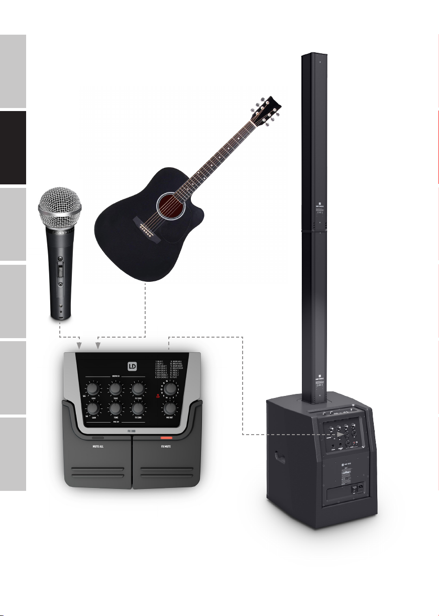
CABLING EXAMPLE 7
TECHNICAL DATA 8
MANUFACTURER’S DECLARATIONS 9
DEUTSCH
SICHERHEITSHINWEISE 10
EINFÜHRUNG 11
ANSCHLÜSSE, BEDIEN- UND ANZEIGEELEMENTE 11
VERKABELUNGSBEISPIEL 14
TECHNISCHE DATEN 15
HERSTELLERERKLÄRUNGEN 16
FRANCAIS
CONSIGNES DE SÉCURITÉ 17
INTRODUCTION 18
RACCORDEMENTS, ÉLÉMENTS DE COMMANDE ET D’AFFICHAGE 18
EXEMPLE DE CÂBLAGE 21
CARACTÉRISTIQUES TECHNIQUES 22
DÉCLARATIONS DU FABRICANT 23
ESPAÑOL
INSTRUCCIONES DE SEGURIDAD 24
INTRODUCCIÓN 25
CONEXIONES, ELEMENTOS DE MANEJO Y ELEMENTOS DE VISUALIZACIÓN 25
EJEMPLO DE CABLEADO 28
DATOS TÉCNICOS 29
DECLARACIONES DEL FABRICANTE 30
POLSKI
ZASADY BEZPIECZEŃSTWA 31
WPROWADZENIE 32
PRZYŁĄCZA, ELEMENTY OBSŁUGI I WSKAŹNIKI 32
PRZYKŁAD OKABLOWANIA 35
DANE TECHNICZNE 36
OŚWIADCZENIA PRODUCENTA 37
ITALIANO
INDICAZIONI SULLA SICUREZZA 38
INTRODUZIONE 39
CONNETTORI, ELEMENTI DI COMANDO E DI VISUALIZZAZIONE 39
ESEMPIO DI CABLAGGIO 42
DATI TECNICI 42
DICHIARAZIONI DEL PRODUTTORE 44
Page 3

ENGLISH
YOU‘ VE MADE THE RI GHT CHOICE!
We hav e design ed this pr oduct to o perat e reliabl y over many y ears . LD Syst ems sta nds for th is with i ts name an d many year s of exp erience
as a man ufact urer of hi gh-qual ity audio p roduc ts. Plea se read t his User ‘s Manua l caref ully, so th at you can b egin maki ng optim um use of
your L D Syste ms produc t quickl y.
You ca n nd more inf ormat ion about L D-SYSTEMS at our I nterne t site W WW.LD-SYSTEMS.COM
SAFETY INFORMATION
1. Ple ase rea d these in struc tions c areful ly.
2. Ke ep all infor mation a nd instr uctio ns in a saf e place.
3. Fol low the ins truc tions.
4. Ob serve a ll safe ty warn ings. Ne ver remo ve safe ty warn ings or ot her infor matio n from the e quipment .
5. Us e the equipm ent only in t he inten ded manner a nd for the in tended pu rpose .
6. Us e only suf cient ly stab le and comp atible s tands and /or mount s (for xed i nstal lation s). Make cer tain th at wall mo unts are p roperl y
ins talled an d secure d. Make cer tain th at the equ ipment is i nstall ed secur ely and can not fall do wn.
7. Duri ng inst allatio n, obser v e the appl icable sa fety r egulat ions for y our count ry.
8. Nev er inst all and oper ate the e quipment n ear radia tors , heat re gister s, ove ns or other s ource s of heat . Make cer tain tha t the equip ment
is alw ays ins talled s o that is c ooled suf cient ly and can not over heat.
9. Nev er place s ources o f igniti on, e.g. , burning c andles, o n the equipm ent.
10. Ve ntilat ion slit s must no t be blocke d.
11. K eep a minimum di stanc e of 20 cm aro und and abov e the devi ce.
12. Do n ot use th is equipme nt in the imme diate v icinit y of wate r (does n ot apply t o special o utdoor e quipment - i n this cas e, obser ve the
spec ial inst ruct ions not ed below. Do n ot expo se this equ ipment to ammable m ateri als, uid s or gases . Avoid dir ect sunli ght!
13. M ake cert ain tha t dripping o r splashe d water c annot en ter the equ ipment . Do not plac e conta iners lle d with liq uids, suc h as vase s or
drin king ves sels, on t he equipme nt.
14. M ake cer tain tha t object s canno t fall int o the devic e.
15. Us e this equ ipment onl y with th e acces sories r ecommend ed and int ended by th e manufac turer.
16. Do n ot open or mo dify thi s equipmen t.
17. Af ter conn ectin g the equipm ent, che ck all cabl es in order t o preven t damage o r acciden ts, e.g ., due to tr ipping ha zards .
18. Dur ing tra nspor t, make ce rtain t hat the e quipment c annot fa ll down and p ossibl y cause pr opert y damage a nd perso nal injuri es.
19. If y our equipm ent is no lon ger func tioning pr operly , if uids or obj ects h ave got ten insid e the equipm ent or if it h as been dam aged in
anot h er way, sw itch it o ff immedi ately an d unplug it f rom the ma ins outl et (if it is a p owered d evice). T his equipme nt may onl y be repair ed
by au thoriz ed, quali ed pers onnel.
20. Cl ean the equ ipment us ing a dry cl oth.
21. C omply wi th all appli cable dis posal la ws in your c ountr y. During di sposal o f packag ing, ple ase sepa rate pl astic an d paper/car dboard .
22. P lasti c bags mus t be kept ou t of reac h of childre n.
23. P lease no te that c hanges or m odica tions no t expre ssly appr oved by t he part y respo nsible f or complia nce could vo id the use r´s
aut horit y to opera te the equ ipment.
FOR EQU IPMENT THAT C ONNECTS T O THE POWER MA INS
24. C AUTIO N: If the po wer cord o f the devic e is equippe d with an e arthin g conta ct, the n it must b e connect ed to an ou tlet wi th a prot ectiv e
gro und. Neve r deacti vate t he prote ctive g round of a p ower cor d.
25. If t he equipmen t has been e xposed t o stron g uc tuatio ns in temper ature (f or examp le, aft er trans port), do n ot swit ch it on immedi ately.
Mois ture and c ondens ation cou ld damage t he equipme nt. Do no t switc h on the equi pment unt il it has r eached r oom temper ature .
26. Be fore con nectin g the equip ment to th e power ou tlet, r st ver ify th at the main s volta ge and fre quency m atch the v alues sp ecied on
the eq uipment . If the equi pment ha s a volta ge selec tion swi tch, con nect th e equipmen t to the pow er outle t only if th e equipmen t values
and th e mains pow er value s match. I f the inclu ded power c ord or pow er adapt er does not t in your wa ll outle t, cont act your e lectr ician.
27. Do no t step on t he power c ord. Make c erta in that th e power ca ble does no t become ki nked, es peciall y at the main s outle t and/or pow er
adap ter and th e equipmen t connec tor.
28. W hen connec ting the e quipmen t, make ce rtain t hat the po wer cord o r power ad apter is al ways f reely ac cessib le. Alwa ys disc onnect t he
equip ment fro m the powe r supply if t he equipme nt is not in u se or if you w ant to cle an the equip ment. A lways u nplug the po wer cord a nd
powe r adapte r from the p ower out let at th e plug or adap ter and no t by pulling o n the cord . Never to uch the pow er cord and p ower adap ter
wit h wet hand s.
29. W henever p ossible , avoid sw itchin g the equipm ent on and of f in quick s uccess ion becau se othe rwise t his can sh orten t he usef ul life of
the equipment.
30. IMP ORTANT I NFORMAT ION: Repla ce fuse s only wit h fuse s of the same t ype and r ating . If a fuse bl ows rep eatedl y, please c ontac t an
aut horise d servi ce centr e.
31. To di sconnec t the equi pment fr om the pow er mains com pletel y, unplug th e power cor d or power ad apter f rom the po wer outl et.
32. I f your devi ce is equipp ed with a V olex powe r connec tor, the ma ting Vole x equipmen t connec tor mus t be unlocke d before i t can be
remo ved. How ever, thi s also mean s that th e equipmen t can slide a nd fall dow n if the pow er cable i s pulled, wh ich can lea d to pers onal
injur ies and/or o ther dam age. For t his reas on, alwa ys be car eful whe n laying c ables.
33. Un plug the po wer cord an d power ad apter fr om the pow er outle t if there i s a risk of a l ightnin g strik e or befor e exte nded perio ds
of dis use.
ENGLISH
DEUTSCHFRANCAIS
ESPAÑOL
ITALIANO POLSKI
3
Page 4
34. The appliance is not to be used by persons (including children) with reduced physical, sensory or mental capabilities, or lack of experience
and knowledge.
ENGLISH
35. Children must be instructed not to play with the device.
36. If the power cord of the device is damaged, do not use the device. The power cord must be replaced by an adequate cable or assembly from an
authorized service center.
CAUTION:
To redu ce the ris k of elect ric shoc k, do not r emove co ver (or back) . There ar e no user se rvice able
par ts insi de. Maint enance an d repair s should be e xclusi vely car ried ou t by qualie d servi ce
DEUTSCH
The w arning tr iangle w ith lig htning s ymbol indi cates d angerou s uninsul ated vol tage in side the uni t, whic h may caus e an
electrical shock .
The w arning tr iangle w ith exc lamat ion mark ind icate s import ant oper ating an d mainte nance ins truc tions.
personnel.
FRANCAIS
War ning! Thi s device is d esigne d for use be low 2000 me tres in a ltitu de.
War ning! Thi s produc t is not int ended for u se in trop ical clim ates.
ESPAÑOL
CAUT ION! HIGH VOLU MES IN AUDIO PR ODUCTS!
Thi s device is m eant for p rofes sional us e. Ther efore, c ommerc ial use of t his equipme nt is subj ect to th e respec tivel y applica ble natio nal acciden t preve ntion ru les and re gulati ons. As a m anufac turer, Ad am Hall is obl igate d to notif y you for mally ab out the ex isten ce of pote ntial
health risks.
Hear ing damag e due to high v olume and pr olonged e xposu re: When in u se, thi s produc t is capabl e of produc ing high so und-pre ssure l evels
(SPL ) that can l ead to irr evers ible hear ing damag e in perf ormers , employe es, and aud ience memb ers. Fo r this rea son, avo id prolon ged
exp osure t o volumes in e xcess o f 90 dB.
INTRODUCTION
POLSKI
The LD Systems FX300 is an intuitive 2-channel mixer with an integrated effects module. It is equipped with a high-impedance instrument input for
stringed instruments with pickups. Thanks to its built-in 48 V phantom power, the microphone channel is suitable for both dynamic and condenser
microphones.
CONNECTIONS, OPERATING AND DISPLAY ELEMENTS
ITALIANO
2
1
1
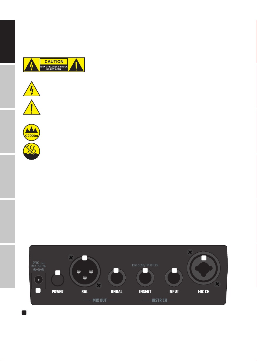
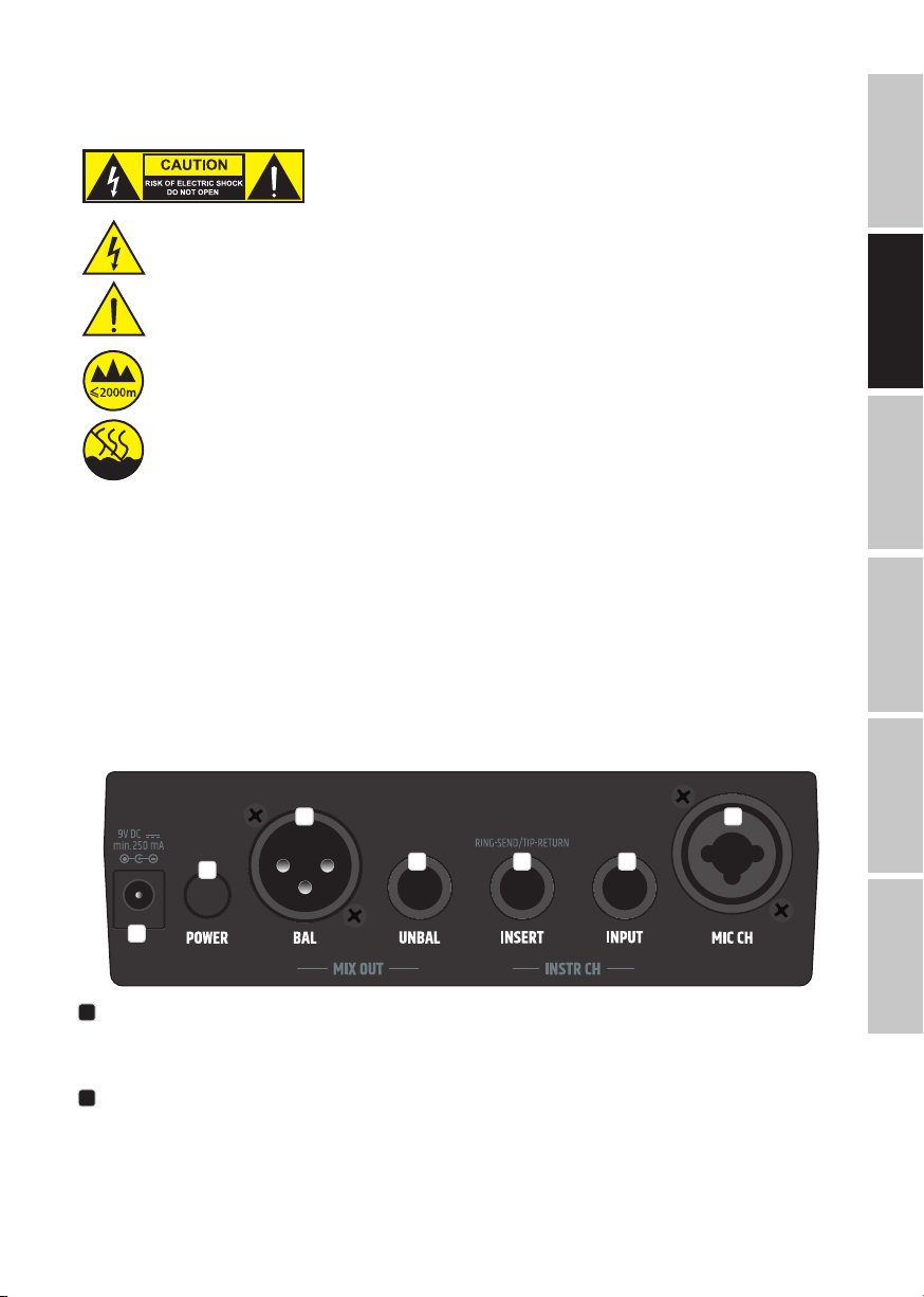
DC SOCKET
Low-voltage socket for the power supply of the device (mains adapter not supplied, 9 V DC 250 mA, centre-negative barrel plug, 5.5 mm external
diameter, 2.1 mm internal).
7
6 5 4
3
4
Page 5
2
POWER
On/off switch. Upon switching on, the SIG and FX CLIP indicator LEDs light up briey.
3
MIC CH
Microphone input with combined XLR and jack socket for connecting dynamic or condenser microphones. 48 V phantom power is always present at
the XLR socket. The microphone channel's jack socket is of a higher impedance than the XLR socket and is also suitable for microphones with a high
output level. Use the MUTE ALL button to mute the device before connecting or disconnecting a microphone.
4
INSTR CH INPUT
High-impedance instrument input with 6.3 mm jack socket. Use the MUTE ALL button to mute the device before connecting or disconnecting an
instrument.
5
INSTR CH INSERT
Series insert for the instrument channel. The insert socket facilitates the insertion of an external effects unit (e.g. phaser, anger or chorus) to the
instrument channel. To do so, you require an insert cable with a 6.3 mm stereo jack plug on one end (Ring = Send, Tip = Return) and two 6.3 mm
mono jack plugs on the other end.
6
MIX OUT UNBAL
Unbalanced line output for connection to an instrument amplier (6.3 mm jack socket). The signal is a mix of the instrument and microphone
channels.
7
MIX OUT BAL
Balanced line output with male 3-pin XLR socket. The signal is a mix of the instrument and microphone channels. This output is used with an XLR
microphone cable to connect the mixer to an active speaker, for example.
ENGLISH
DEUTSCHFRANCAIS
ESPAÑOL
8
9
13 12
8
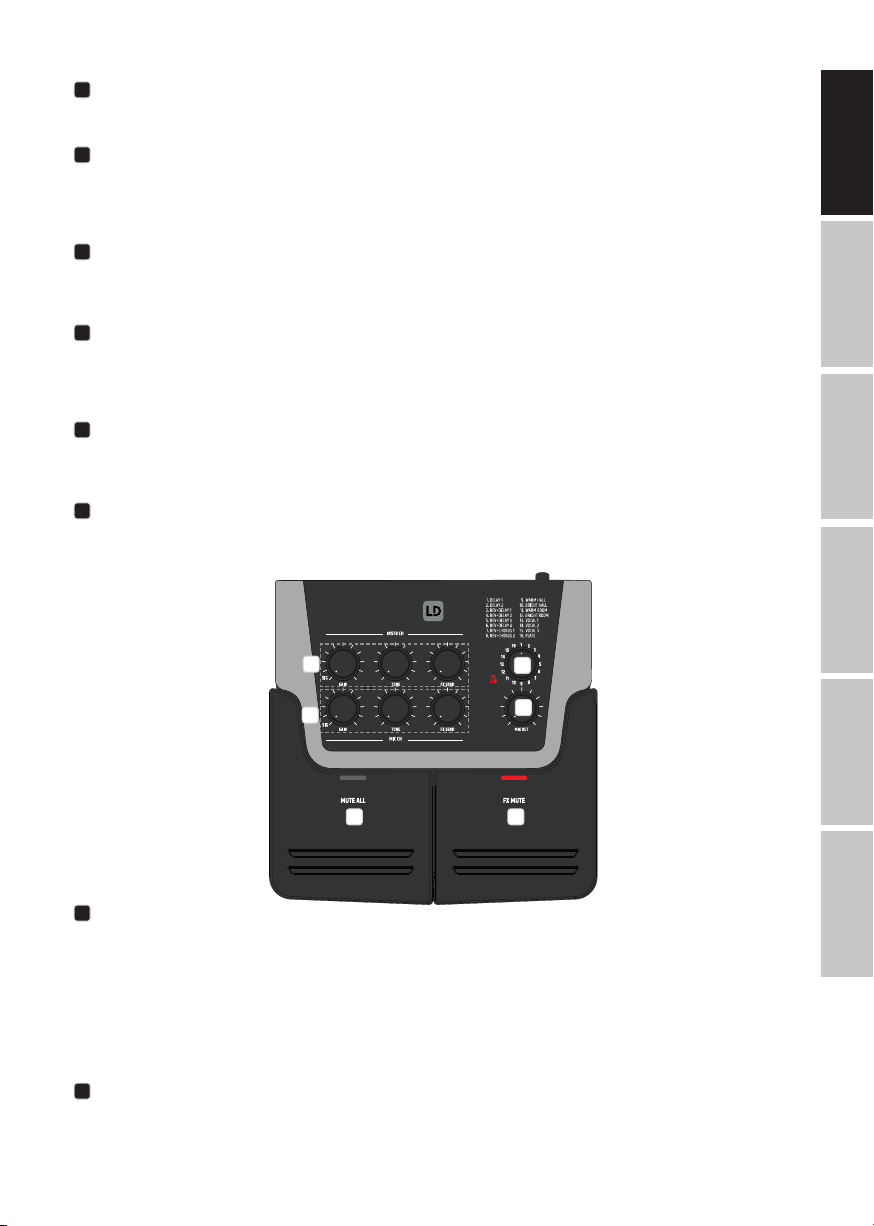
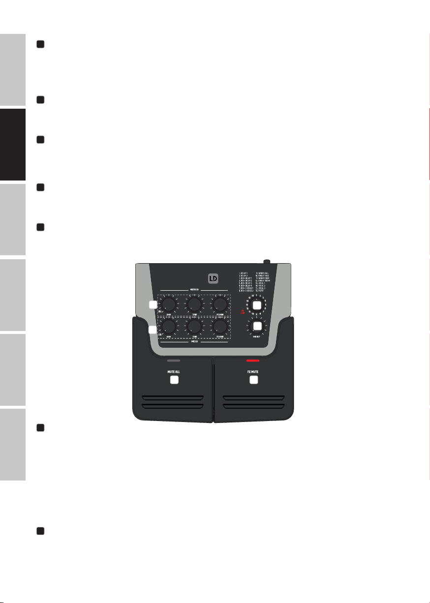
INSTR CH
Operating and display elements for the instrument channel.
GAIN – Controls amplication of the instrument signal. The corresponding SIG LED indicator lights up white when a signal is present. If the signal is 1
dB below the distortion threshold, the LED lights up violet. If the instrument input is driven beyond the distortion threshold, the SIG LED lights up red
and signal distortion may occur. Set the Gain control so that the SIG LED does not light up red when there are volume peaks.
TONE – 10 kHz high-shelf equalizer. In the centre position, the signal is unaffected. Turn to the left to reduce highs by up to 8 dB. Turn to the right to
increase highs by up to 7 dB.
FX SEND – Level control for mixing the instrument signal with the internal digital effects processor. Ensure that the red FX CLIP LED does not light up.
9
MIC CH
Operating and display elements for the microphone channel.
10
11
ITALIANO POLSKI
5
Page 6
GAIN – Controls amplication of the microphone signal. The corresponding SIG LED indicator lights up white when a signal is present. If the signal is 1
dB below the distortion threshold, the LED lights up violet. If the instrument input is driven beyond the distortion threshold, the SIG LED lights up red
ENGLISH
and signal distortion may occur. Set the Gain control so that the SIG LED does not light up red when there are volume peaks.
TONE – 8 kHz high-shelf equalizer. In the centre position the signal is unaffected. Turn to the left to reduce highs by up to 8 dB. Turn to the right to
increase highs by up to 5 dB.
FX SEND – Level control for mixing the microphone signal with the internal digital effects processor. Ensure that the red FX CLIP LED does not light
up.
10
DEUTSCH
FRANCAIS
DIGITAL EFFECTS PROCESSOR
Rotate the encoder to select one of the 16 effects presets. A list of available effects is printed above the preset encoder. The red FX CLIP LED lights up
if the signal reaches the distortion threshold of the internal effects processor. To avoid signal distortion, ensure that the FX CLIP LED does not light
up if there are volume peaks. Reduce the effects send level control FX SEND on the affected channel.
11
MIX OUT
Level control for the combined MIX OUT line out signal. Rotate to the left to decrease and to the right to increase the volume.
12
FX MUTE
Button for muting the effects signal. Push the button to mute the effects signal and once again to unmute it. When muted, the corresponding red
indicator LED lights up.
13
MUTE ALL
Button for muting the combined signal. Push the button to mute the combined signal and once again to unmute it. When muted, the corresponding
red indicator LED lights up.
ESPAÑOL
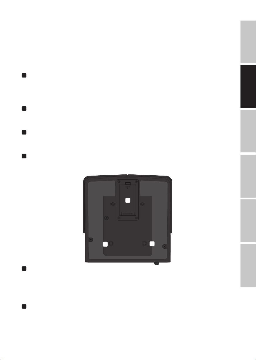
OPEN
14
9V BATTERY
POLSKI
15
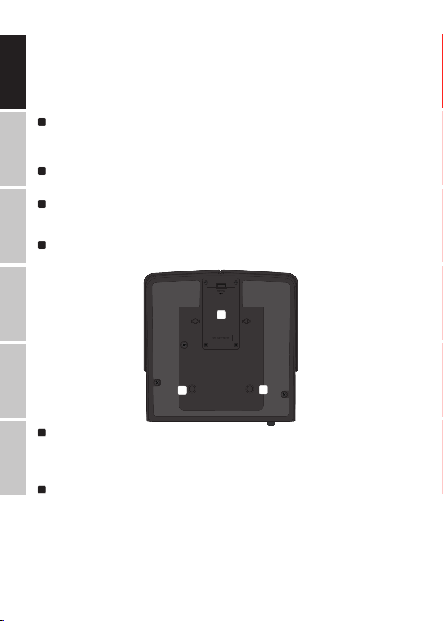
BATTERY COMPARTMENT
14
ITALIANO
Battery compartment for the 9 V block battery. To replace the battery, open the battery compartment by pushing the compartment lid lever in the
direction marked "OPEN" and ip the lid upwards. Remove the used battery, attach the clip to the new battery (1 x 9 V block, alkaline) and insert it
in the battery compartment. Replace the battery compartment cover on the housing and click it into place. If you do not use the device for a long
period, remove the battery to prevent damage to the device from a leaking battery.
MOUNTING POINTS
15
Mounting points for the optionally available microphone stand adapter LDVIBZMADAPTOR.
15
6
Page 7
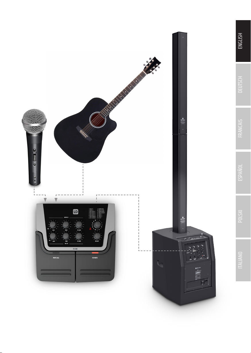
CABLING EXAMPLE
ENGLISH
DEUTSCHFRANCAIS
ESPAÑOL
MIC CH
INSTR CH INPUT
MIX OUT
LINE INPUT
ITALIANO POLSKI
7
Page 8

TECHNICAL DATA
ENGLISH
Product number: LDFX300
Product type: Artist Pedal
Type: Live/home recording
No. of channels: 2
Microphone channels
DEUTSCH
Microphone channels: 1
Microphone channel input connections: XLR/6.3 mm combination jack
Microphone channel XLR input type: Electronically balanced
Microphone channel frequency response: 50 Hz (HPF) to 20 kHz (-3 dB)
Microphone channel XLR input gain range: 42 dB
Microphone channel XLR input THD: <0.03%
FRANCAIS
Microphone channel XLR input impedance: 6 kOhm
Microphone channel XLR input S/N ratio: <103 dB (a)
Phantom power: +48 V DC on XLR input
Microphone channel jack input type: Electronically balanced
Microphone channel jack input gain range: 20 dB
Microphone channel jack input THD: <0.045%
ESPAÑOL
Microphone channel jack input impedance: 10 kOhm
Microphone channel jack input S/N ratio: 106 dB
Microphone channel EQ: +5/-8 dB @ 8 kHz
Microphone channel controls: GAIN, TONE, FX SEND
Microphone channel display elements: Channel signal, tri-colour LED (SIG)
Instrument channels
POLSKI
Instrument channels: 1
Instrument channel input type: Unbalanced high impedance
Instrument channel gain range: 23 dB
Instrument channel THD: <0.03%
Instrument channel impedance: 1M Ohm
Instrument channel S/N ratio: 115 dB
ITALIANO
Instrument channel EQ: +7/-8 dB @ 10 kHz
Instrument channel insert: 1
Instrument channel insert connections: 6.3 mm stereo jack (TIP = Return/RING = Send)
Instrument channel controls: GAIN, TONE, FX SEND
Instrument channel display elements: Channel signal, tri-colour LED (SIG)
8
Page 9

Main section
Line outputs: 2
Line output connections: XLR and 6.3 mm jack
XLR output level: Max. +17 dBu, balanced
XLR output impedance: 150 ohms
Jack output level: Max. +5 dBV, unbalanced
Jack output impedance: 40 ohms
Digital effects processor: 1
No. of presets: 16
Main section operating controls: DFX presets encoder, MIX OUT, POWER, FX MUTE, MUTE ALL
Main section display elements: Effects clip, red LED (FX CLIP), FX MUTE LED, MUTE ALL LED
General specications
Power supply: - 9 V block battery (approx. 4–5 hours operating time with alkaline battery)
- External mains adapter 9 V DC/250 mA with barrel plug external diameter 5.5 mm,
internal 2.1 mm, centre negative polarity (not supplied)
Ambient operating temperature: 0°C to +40°C
Relative air humidity: <80%, non-condensing
Dimensions (W x H x D): 160 x 55 x 163 mm
Weight: 0.65 kg
Additional features: Microphone stand-mount ready
(adapter optionally available: LDVIBZMSADAPTOR)
MANUFACTURER´S DECLARATIONS
ENGLISH
DEUTSCHFRANCAIS
ESPAÑOL
MANUFACTURER‘S WARRANTY & LIMITATIONS OF LIABILITY
You can nd our current warranty conditions and limitations of liability at: https://cdn-shop.adamhall.com/media/pdf/MANUFACTURERS-DECLARATIONS_
LD_SYSTEMS.pdf To request warranty service for a product, please contact Adam Hall GmbH, Adam-Hall-Str. 1,
61267 Neu Anspach / Email: Info@adamhall.com / +49 (0)6081 / 9419-0.
CORRECT DISPOSAL OF THIS PRODUCT
(valid in the European Union and other European countries with a differentiated waste collection system)
This symbol on the product, or on its documents indicates that the device may not be treated as household waste. This is to avoid environmental damage or personal injury due to uncontrolled waste disposal. Please dispose of this product separately from other waste and have it
recycled to promote sustainable economic activity. Household users should contact either the retailer where they purchased this product, or their
local government ofce, for details on where and how they can recycle this item in an environmentally friendly manner. Business users should
contact their supplier and check the terms and conditions of the purchase contract. This product should not be mixed with other commercial waste
for disposal.
CE Compliance
Adam Hall GmbH states that this product meets the following guidelines (where applicable):
R&TTE (1999/5/EC) or RED (2014/53/EU) from June 2017
Low voltage directive (2014/35/EU)
EMV directive (2014/30/EU)
RoHS (2011/65/EU)
The complete declaration of conformity can be found at www.adamhall.com.
Furthermore, you may also direct your enquiry to info@adamhall.com.
EU DECLARATION OF CONFORMITY
Hereby, Adam Hall GmbH declares that this radio equipment type is in compliance with Directive 2014/53/EU.
The full text of the EU declaration of conformity is available at the following
internet address: www.adamhall.com/compliance/
ITALIANO POLSKI
9
Page 10

DEUTSCH
ENGLISH
SIE HABEN DIE RICHTIGE WAHL GETROFFEN!
Dieses Gerät wurde unter hohen Qualitätsanforderungen entwickelt und gefertigt, um viele Jahre einen reibungslosen Betrieb zu gewährleisten.
Dafür steht LD Systems mit seinem Namen und der langjährigen Erfahrung als Hersteller hochwertiger Audioprodukte. Bitte lesen Sie diese Bedienungsanleitung sorgfältig, damit Sie Ihr neues Produkt von LD Systems schnell optimal einsetzen können.
Mehr Informationen zu LD SYSTEMS nden Sie auf unserer Internetseite WWW.LD-SYSTEMS.COM
SICHERHEITSHINWEISE
1. Lesen Sie diese Anleitung bitte sorgfältig durch.
2. Bewahren Sie alle Informationen und Anleitungen an einem sicheren Ort auf.
DEUTSCH
3. Befolgen Sie die Anweisungen.
4. Beachten Sie alle Warnhinweise. Entfernen Sie keine Sicherheitshinweise oder andere Informationen vom Gerät.
5. Verwenden Sie das Gerät nur in der vorgesehenen Art und Weise.
6. Verwenden Sie ausschließlich stabile und passende Stative bzw. Befestigungen (bei Festinstallationen). Stellen Sie sicher, dass Wandhalterungen
ordnungsgemäß installiert und gesichert sind. Stellen Sie sicher, dass das Gerät sicher installiert ist und nicht herunterfallen kann.
7. Beachten Sie bei der Installation die für Ihr Land geltenden Sicherheitsvorschriften.
8. Installieren und betreiben Sie das Gerät nicht in der Nähe von Heizkörpern, Wärmespeichern, Öfen oder sonstigen Wärmequellen. Sorgen Sie dafür,
dass das Gerät immer so installiert ist, dass es ausreichend gekühlt wird und nicht überhitzen kann.
9. Platzieren Sie keine Zündquellen wie z.B. brennende Kerzen auf dem Gerät.
FRANCAIS
10. Lüftungsschlitze dürfen nicht blockiert werden.
11. Halten Sie einen Mindestabstand von 20 cm seitlich und oberhalb des Geräts ein.
12. Betreiben Sie das Gerät nicht in unmittelbarer Nähe von Wasser. Bringen Sie das Gerät nicht mit brennbaren Materialien, Flüssigkeiten oder
Gasen in Berührung. Direkte Sonneneinstrahlung vermeiden!
13. Sorgen Sie dafür, dass kein Tropf- oder Spritzwasser in das Gerät eindringen kann. Stellen Sie keine mit Flüssigkeit gefüllten Behältnisse wie
Vasen oder Trinkgefäße auf das Gerät.
14. Sorgen Sie dafür, dass keine Gegenstände in das Gerät fallen können.
15. Betreiben Sie das Gerät nur mit dem vom Hersteller empfohlenen und vorgesehenen Zubehör.
16. Öffnen Sie das Gerät nicht und verändern Sie es nicht.
17. Überprüfen Sie nach dem Anschluss des Geräts alle Kabelwege, um Schäden oder Unfälle, z. B. durch Stolperfallen zu vermeiden.
ESPAÑOL
18. Achten Sie beim Transport darauf, dass das Gerät nicht herunterfallen und dabei möglicherweise Sach- und Personenschäden
verursachen kann.
19. Wenn Ihr Gerät nicht mehr ordnungsgemäß funktioniert, Flüssigkeiten oder Gegenstände in das Geräteinnere gelangt sind, oder das Gerät an-
derweitig beschädigt wurde, schalten Sie es sofort aus und trennen es von der Netzsteckdose (sofern es sich um ein aktives Gerät handelt). Dieses
Gerät darf nur von autorisiertem Fachpersonal repariert werden.
20. Verwenden Sie zur Reinigung des Geräts ein trockenes Tuch.
21. Beachten Sie alle in Ihrem Land geltenden Entsorgungsgesetze. Trennen Sie bei der Entsorgung der Verpackung bitte Kunststoff und Papier bzw.
Kartonagen voneinander.
22. Kunststoffbeutel müssen außer Reichweite von Kindern aufbewahrt werden.
23. Sämtliche vom Benutzer vorgenommenen Änderungen und Modikationen, denen die für die Einhaltung der Richtlinien verantwortliche Partei
POLSKI
nicht ausdrücklich zugestimmt hat, können zum Entzug der Betriebserlaubnis für das Gerät führen.
BEI GERÄTEN MIT NETZANSCHLUSS
24. ACHTUNG: Wenn das Netzkabel des Geräts mit einem Schutzkontakt ausgestattet ist, muss es an einer Steckdose mit Schutzleiter angeschlossen
werden. Deaktivieren Sie niemals den Schutzleiter eines Netzkabels.
25. Schalten Sie das Gerät nicht sofort ein, wenn es starken Temperaturschwankungen ausgesetzt war (beispielsweise nach dem Transport). Feuchtigkeit und Kondensat könnten das Gerät beschädigen. Schalten Sie das Gerät erst ein, wenn es Zimmertemperatur erreicht hat.
26. Bevor Sie das Gerät an die Steckdose anschließen, prüfen Sie zuerst, ob die Spannung und die Frequenz des Stromnetzes mit den auf dem Gerät
angegebenen Werten übereinstimmen. Verfügt das Gerät über einen Spannungswahlschalter, schließen Sie das Gerät nur an die Steckdose an,
ITALIANO
wenn die Gerätewerte mit den Werten des Stromnetzes übereinstimmen. Wenn das mitgelieferte Netzkabel bzw. der mitgelieferte Netzadapter
nicht in Ihre Netzsteckdose passt, wenden Sie sich an Ihren Elektriker.
27. Treten Sie nicht auf das Netzkabel. Sorgen Sie dafür, dass spannungsführende Kabel speziell an der Netzbuchse bzw. am Netzadapter und der
Gerätebuchse nicht geknickt werden.
28. Achten Sie bei der Verkabelung des Geräts immer darauf, dass das Netzkabel bzw. der Netzadapter stets frei zugänglich ist. Trennen Sie das
Gerät stets von der Stromzuführung, wenn das Gerät nicht benutzt wird, oder Sie das Gerät reinigen möchten. Ziehen Sie Netzkabel und Netzadapter
immer am Stecker bzw. am Adapter und nicht am Kabel aus der Steckdose. Berühren Sie Netzkabel und Netzadapter niemals mit nassen Händen.
29. Schalten Sie das Gerät möglichst nicht schnell hintereinander ein und aus, da sonst die Lebensdauer des Geräts beeinträchtigt werden könnte.
30. WICHTIGER HINWEIS: Ersetzen Sie Sicherungen ausschließlich durch Sicherungen des gleichen Typs und Wertes. Sollte eine Sicherung wiederholt
auslösen, wenden Sie sich bitte an ein autorisiertes Servicezentrum.
31. Um das Gerät vollständig vom Stromnetz zu trennen, entfernen Sie das Netzkabel bzw. den Netzadapter aus der Steckdose.
32. Wenn Ihr Gerät mit einem verriegelbaren Netzanschluss bestückt ist, muss der passende Gerätestecker entsperrt werden, bevor er entfernt werden kann. Das bedeutet aber auch, dass das Gerät durch ein Ziehen am Netzkabel verrutschen und herunterfallen kann, wodurch Personen verletzt
werden und/oder andere Schäden auftreten können. Verlegen Sie Ihre Kabel daher immer sorgfältig.
33. Entfernen Sie Netzkabel und Netzadapter aus der Steckdose bei Gefahr eines Blitzschlags oder wenn Sie das Gerät länger nicht verwenden.
34. Das Gerät darf nicht von Personen (einschließlich Kindern) mit eingeschränkten körperlichen, sensorischen oder geistigen Fähigkeiten oder
mangelnder Erfahrung und Kenntnis benutzt werden.
10
Page 11
35. Kinder müssen angewiesen werden, nicht mit dem Gerät zu spielen.
36. Wenn das Netzkabel des Geräts beschädigt ist, darf das Gerät nicht verwendet werden. Das Netzkabel muss durch ein adäquates Kabel oder eine
spezielle Baugruppe von einem autorisierten Service-Center ersetzt werden.
ACHTUNG
Entfernen Sie niemals die Abdeckung, da sonst das Risiko eines elektrischen Schlages besteht. Im In-
neren des Geräts benden sich keine Teile, die vom Bediener repariert oder gewartet werden können.
Lassen Sie Wartung und Reparaturen ausschließlich von qualiziertem Servicepersonal durchführen.
Das gleichseitige Dreieck mit Blitzsymbol warnt vor nichtisolierten, gefährlichen Spannungen im Geräteinneren, die einen elektrischen
Schlag verursachen können.
Das gleichseitige Dreieck mit Ausrufungszeichen kennzeichnet wichtige Bedienungs- und Wartungshinweise.
Warnung! Dieses Gerät ist für eine Nutzung bis zu einer Höhe von maximal 2000 Metern über dem Meeresspiegel bestimmt.
Warnung! Dieses Gerät ist nicht für den Einsatz in tropischen Klimazonen bestimmt.
ACHTUNG HOHE LAUTSTÄRKEN BEI AUDIOPRODUKTEN!
Dieses Gerät ist für den professionellen Einsatz vorgesehen. Der kommerzielle Betrieb dieses Geräts unterliegt den jeweils gültigen nationalen
Vorschriften und Richtlinien zur Unfallverhütung. Als Hersteller ist Adam Hall gesetzlich verpichtet, Sie ausdrücklich auf mögliche Gesundheitsrisiken
hinzuweisen. Gehörschäden durch hohe Lautstärken und Dauerbelastung: Bei der Verwendung dieses Produkts können hohe Schalldruckpegel
(SPL) erzeugt werden, die bei Künstlern, Mitarbeitern und Zuschauern zu irreparablen Gehörschäden führen können. Vermeiden Sie länger anhaltende
Belastung durch hohe Lautstärken über 90 dB.
ENGLISH
DEUTSCHFRANCAIS
EINFÜHRUNG
Das LD Systems FX300 ist ein intuitiv bedienbares Mischpult mit zwei Kanälen und integriertem Effektmodul. Es verfügt über einen hochohmigen
Instrumenteneingang zum Anschließen eines Saiteninstruments mit Tonabnehmer und dank der integrierten 48V Phantomspeisung ist der Mikrofonkanal, neben der Verwendung von dynamischen Mikrofonen, auch für die Verwendung von Kondensatormikrofonen geeignet.
ANSCHLÜSSE, BEDIEN- UND ANZEIGEELEMENTE
7
2
1
1
DC-BUCHSE
Kleinspannungsbuchse für die Spannungsversorgung des Geräts (Netzadapter nicht im Lieferumfang, 9V DC 250mA, Minus innen, Hohlstecker außen
5,5 mm, innen 2,1 mm).
2
POWER
Ein- bzw. Ausschalter. Beim Einschalten leuchten die Anzeige-LEDs SIG und FX CLIP für kurze Zeit auf.
6 5 4
3
ESPAÑOL
ITALIANO POLSKI
11
Page 12
3
ENGLISH
MIC CH
Mikrofoneingang mit XLR/Klinken Kombibuchse zum Anschließen eines dynamischen Mikrofons oder eines Kondensatormikrofons. Die 48V Pantomspeisung liegt permanent an der XLR-Buchse an. Der Klinkeneingang des Mikrofonkanals ist hochohmiger als der XLR-Eingang und ist daher auch für
Mikrofone mit hohem Ausgangspegel geeignet. Schalten Sie das Gerät mit Hilfe des Tasters MUTE ALL stumm, bevor Sie ein Mikrofon anschließen
oder vom Gerät trennen.
4
INSTR CH INPUT
Hochohmiger Instrumenteneingang mit 6,3 mm Klinkenbuchse. Schalten Sie das Gerät mit Hilfe des Tasters MUTE ALL stumm, bevor Sie ein Instrument anschließen oder vom Gerät trennen.
DEUTSCH
5
INSTR CH INSERT
Serieller Einschleifweg für den Instrumentenkanal. Die Insert-Buchse bietet die Möglichkeit, ein externes Effektgerät, wie z.B. einen Phaser, Flanger
oder Chorus in den Instrumentenkanal einzuschleifen. Hierfür benötigen Sie ein Insert-Kabel mit einem 3-poligen 6,3 mm Klinkenstecker auf der
einen (Ring = Send / Tip = Return), und zwei 2-poligen 6,3 mm Klinkensteckern auf der anderen Seite.
6
MIX OUT UNBAL
Unsymmetrischer Line-Ausgang zum Anschließen an einen Instrumentenverstärker (6,3 mm Klinkenbuchse). Das anliegende Signal ist ein Mix aus
FRANCAIS
Instrumenten- und Mikrofonkanal.
7
MIX OUT BAL
Symmetrischer Line-Ausgang mit männlicher 3-Pol XLR-Buchse. Das anliegende Signal ist ein Mix aus Instrumenten- und Mikrofonkanal. Der Ausgang
wird verwendet, um das Mischpult mit Hilfe eines Mikrofonkabels beispielsweise an einer Aktivbox anzuschließen.
ESPAÑOL
8
9
10
11
POLSKI
13 12
8
ITALIANO
INSTR CH
Bedien- und Anzeigeelemente für den Instrumentenkanal.
GAIN - Regler für die Verstärkung des anliegenden Instrumentensignals. Die dazugehörende Anzeige-LED SIG leuchtet bei einem anliegenden Signal
weiß, liegt das Signal 1 dB unter der Verzerrungsgrenze, leuchtet die LED violett. Wird der Instrumenteneingang an der Verzerrungsgrenze betrieben,
leuchtet die SIG-LED rot und Signalverzerrungen können auftreten. Stellen Sie den Gain-Regler so ein, dass die SIG-LED auch bei Pegelspitzen nicht
rot leuchtet.
TONE - Hi-Shelf Equalizer bei 10 kHz. In Mittelstellung bleibt das anliegende Signal unbearbeitet, nach links gedreht werden die Höhen um bis zu 8 dB
abgesenkt, nach rechts gedreht, um bis zu 7 dB angehoben.
FX SEND - Pegelsteller für die Zumischung des Instrumentensignals auf das interne digitale Effektgerät. Achten Sie dabei darauf, dass die rote
Anzeige-LED FX CLIP nicht leuchtet.
9
MIC CH
Bedien- und Anzeigeelemente für den Mikrofonkanal.
12
Page 13
GAIN - Regler für die Verstärkung des anliegenden Mikrofonsignals. Die dazugehörende Anzeige-LED SIG leuchtet bei einem anliegenden Signal
weiß, liegt das Signal 1 dB unter der Verzerrungsgrenze, leuchtet die LED violett. Wird der Instrumenteneingang an der Verzerrungsgrenze betrieben,
leuchtet die SIG-LED rot und Signalverzerrungen können auftreten. Stellen Sie den Gain-Regler so ein, dass die SIG-LED auch bei Pegelspitzen nicht
rot leuchtet.
TONE - Hi-Shelf Equalizer bei 8 kHz. In Mittelstellung bleibt das anliegende Signal unbearbeitet, nach links gedreht werden die Höhen um bis zu 8 dB
abgesenkt, nach rechts gedreht, um bis zu 5 dB angehoben.
FX SEND - Pegelsteller für die Zumischung des Mikrofonsignals auf das interne digitale Effektgerät. Achten Sie dabei darauf, dass die rote Anzeige-LED FX CLIP nicht leuchtet.
10
DIGITALES EFFEKTGERÄT
Um eines der 16 Effekt-Presets auszuwählen, drehen Sie den Encoder in die entsprechende Position. Eine Liste der enthaltenen Effekte bendet
sich abgedruckt über dem Preset-Encoder. Die rote Anzeige-LED FX CLIP leuchtet, falls das anliegende Signal die Verzerrungsgrenze des internen
Effektgeräts erreicht. Um Signalverzerrungen zu vermeiden, achten Sie darauf, dass die Anzeige-LED FX CLIP auch bei Pegelspitzen nicht leuchtet.
Reduzieren Sie hierfür den Effekt-Send-Pegel am Pegelsteller FX SEND des entsprechenden Kanals.
11
MIX OUT
Pegelsteller für das an den Line-Ausgängen MIX OUT anliegende Gesamtsignal. Nach links gedreht verringert sich, nach rechts gedreht erhöht sich
die Lautstärke.
12
FX MUTE
Taster zum Stummschalten des Effektsignals. Drücken Sie den Taster, um das Effektsignal stummzuschalten und nochmals, um die Stummschaltung
wieder aufzuheben. Während der Stummschaltung leuchtet die dazugehörende rote Anzeige-LED.
13
MUTE ALL
Taster zum Stummschalten des Gesamtsignals. Drücken Sie den Taster, um das Gesamtsignal stummzuschalten und nochmals, um die Stummschaltung wieder aufzuheben. Während der Stummschaltung leuchtet die dazugehörende rote Anzeige-LED.
ENGLISH
DEUTSCHFRANCAIS
OPEN
14
9V BATTERY
15
BATTERIEFACH
14
15
Batteriefach für eine 9V Block Batterie. Zum Austauschen der Batterie öffnen Sie das Batteriefach des Geräts, indem Sie den Verriegelungshebel des
Batteriefachdeckels in Richtung der Beschriftung „OPEN“ drücken und den Deckel nach oben aufklappen. Entnehmen Sie die verbrauchte Batterie,
schließen den Batterieclip an der frischen Batterie an (1x 9V Block, Alkaline) und setzen sie ins Batteriefach ein. Klappen Sie den Batteriefachdeckel
nun wieder auf das Gehäuse, bis der Verriegelungshebel einrastet. Nutzen Sie das Gerät für längere Zeit nicht, entnehmen Sie bitte die Batterie, um
Beschädigungen am Gerät durch eine auslaufende Batterie zu vermeiden.
MONTAGEPUNKTE
15
Montagepunkte für den optional erhältlichen Mikrofonstativ-Adapter LDVIBZMSADAPTOR.
ESPAÑOL
ITALIANO POLSKI
13
Page 14
VERKABELUNGSBEISPIEL
ENGLISH
DEUTSCH
FRANCAIS
ESPAÑOL
POLSKI
ITALIANO
14
MIC CH
INSTR CH INPUT
MIX OUT
LINE INPUT
Page 15

TECHNISCHE DATEN
Artikelnummer: LDFX300
Produktart: Artist Pedal
Typ: Live / Home Recording
Anzahl Kanäle: 2
Mikrofonkanäle
Mikrofonkanäle: 1
Mikrofonkanal Eingangsanschlüsse: XLR/6,3 mm Kombibuchse
Mikrofonkanal XLR-Eingang Eingangstyp: elektronisch symmetriert
Frequenzgang Mikrofonkanal: 50 Hz (HPF) - 20 kHz (-3 dB)
Verstärkungsbereich Mikrofonkanal XLR-Eingang: 42 dB
THD Mikrofonkanal XLR-Eingang: <0.03 %
Impedanz Mikrofonkanal XLR-Eingang: 6 kOhm
S/N Ratio Mikrofonkanal XLR-Eingang: <103 dB (a)
Phantomspeisung: +48 V DC auf XLR Input
Mikrofonkanal Klinkeneingang Eingangstyp: elektronisch symmetriert
Verstärkungsbereich Mikrofonkanal Klinkeneingang: 20 dB
THD Mikrofonkanal Klinkeneingang: <0.045 %
Impedanz Mikrofonkanal Klinkeneingang: 10 kOhm
S/N Ratio Mikrofonkanal Klinkeneingang: 106 dB
Mikrofonkanal Equalizer: +5/-8 dB @ 8 kHz
Bedienelemente Mikrofonkanal: GAIN, TONE, FX SEND
Anzeigeelemente Mikrofonkanal: Kanal-Signal, 3-farbige LED (SIG)
Instrumentenkanäle
Instrumentenkanäle: 1
Instrumentenkanal Eingangstyp: Hochohmig unsymmetrisch
Verstärkungsbereich Instrumentenkanal: 23 dB
THD Instrumentenkanal: <0.03 %
Impedanz Instrumentenkanal: 1M Ohm
S/N Ratio Instrumentenkanal: 115 dB
Instrumentenkanal Equalizer: +7/-8 dB @ 10 kHz
Kanal-Insert Instrumentenkanal: 1
Kanal-Insert Anschlüsse Instrumentenkanal: 6,3 mm Stereoklinke (TIP= Return / RING= Send)
Bedienelemente Instrumentenkanal: GAIN, TONE, FX SEND
Anzeigeelemente Instrumentenkanal: Kanal-Signal, 3-farbige LED (SIG)
Main Sektion
Line-Ausgänge: 2
Line-Ausgangsanschlüsse: XLR und 6,3 mm Klinke
Ausgangspegel XLR-Ausgang: Max. +17 dBu, symmetrisch
Impedanz XLR-Ausgang: 150 Ohm
ENGLISH
DEUTSCHFRANCAIS
ESPAÑOL
ITALIANO POLSKI
15
Page 16

Ausgangspegel Klinkenausgang: Max. +5 dBV, unsymmetrisch
ENGLISH
Impedanz Klinkenausgang: 40 Ohm
Digitaler Effektprozessor: 1
Anzahl Presets: 16
Bedienelemente Main Sektion: DFX Presets Encoder, MIX OUT, POWER, FX MUTE, MUTE ALL
Anzeigeelemente Main Sektion: Effekt-Clip, rote LED (FX CLIP), FX MUTE LED, MUTE ALL LED
Generelle Spezikationen
DEUTSCH
Stromversorgung: - 9 V Block Batterie (Betriebsdauer mit Alkaline Batterie ca. 4 - 5 Stunden)
Umgebungstemperatur in Betrieb: 0 °C to +40 °C
Relative Luftfeuchtigkeit: < 80 %, nicht kondensierend
Abmessungen (B x H x T): 160 x 55 x 163 mm
FRANCAIS
Gewicht: 0,65 kg
Weitere Eigenschaften: Vorbereitung für Mikrofonstativ-Montage
- Externer Netzadapter 9VDC / 250mA mit Hohlstecker außen 5,5 mm, innen 2,1 mm,
Polung Minus innen (nicht im Lieferumfang enthalten)
(Adapter optional erhältlich: LDVIBZMSADAPTOR)
HERSTELLERERKLÄRUNGEN
HERSTELLERGARANTIE & HAFTUNGSBESCHRÄNKUNG
Unsere aktuellen Garantiebedingungen und Haftungsbeschränkung nden Sie unter: https://cdn-shop.adamhall.com/media/pdf/MANUFACTURERS-
ESPAÑOL
DECLARATIONS_LD_SYSTEMS.pdf. Im Service Fall wenden Sie sich bitte an Adam Hall GmbH, Adam-Hall-Str. 1,
61267 Neu Anspach / E-Mail Info@adamhall.com / +49 (0)6081 / 9419-0.
KORREKTE ENTSORGUNG DIESES PRODUKTS
(Gültig in der Europäischen Union und anderen europäischen Ländern mit Mülltrennung) Dieses Symbol auf dem Produkt oder dazugehörigen
Dokumenten weist darauf hin, dass das Gerät am Ende der Produktlebenszeit nicht zusammen mit dem normalen Hausmüll entsorgt werden
darf, um Umwelt- oder Personenschäden durch unkontrollierte Abfallentsorgung zu vermeiden. Bitte entsorgen Sie dieses Produkt getrennt von
anderen Abfällen und führen es zur Förderung nachhaltiger Wirtschaftskreisläufe dem Recycling zu. Als Privatkunde erhalten Sie Informationen zu
umweltfreundlichen Entsorgungsmöglichkeiten über den Händler, bei dem das Produkt erworben wurde, oder über die entsprechenden regionalen
Behörden. Als gewerblicher Nutzer kontaktieren Sie bitte Ihren Lieferanten und prüfen die ggf. vertraglich vereinbarten Konditionen zur Entsorgung der
POLSKI
Geräte. Dieses Produkt darf nicht zusammen mit anderen gewerblichen Abfällen entsorgt werden.
CE-Konformität
Hiermit erklärt die Adam Hall GmbH, dass dieses Produkt folgenden Richtlinien entspricht (soweit zutreffend):
R&TTE (1999/5/EG) bzw. RED (2014/53/EU) ab Juni 2017
Niederspannungsrichtlinie (2014/35/EU)
EMV-Richtlinie (2014/30/EU)
RoHS (2011/65/EU)
Die vollständige Konformitätserklärung nden Sie unter www.adamhall.com.
Des Weiteren können Sie diese auch unter info@adamhall.com anfragen.
ITALIANO
EG-KONFORMITÄTSERKLÄRUNG
Hiermit erklärt die Adam Hall GmbH, dass dieser Funkanlagentyp der Richtlinie 2014/53/EU entspricht.
Der vollständige Text der EU-Konformitätserklärung ist unter der folgenden
Internetadresse verfügbar: www.adamhall.com/compliance/
16
Page 17

FRANCAIS
VOUS AVEZ FAIT LE BON CHOIX!
Cet appareil a été développé et fabriqué en appliquant des exigences de qualité très élevées : il garantit des années de fonctionnement sans
problème. Grâce à de nombreuses années d‘expérience, LD Systems est un nom connu dans le domaine des produits audio haut de gamme. Veuillez
lire attentivement ce Manuel Utilisateur : vous apprendrez rapidement à utiliser votre appareil LD Systems de façon optimale.
Pour plus d‘informations sur LD Systems, visitez notre site Web, WWW.LD-SYSTEMS.COM
MESURES PRÉVENTIVES
1. Veuillez lire attentivement ce manuel.
2. Rangez tous les documents d‘information et d‘instructions en lieu sûr.
3. Veuillez suivre toutes les instructions
4. Observez tous les messages d‘avertissement N‘enlevez pas de l‘appareil les étiquettes de sécurité ou autres informations.
5. N‘utilisez l‘appareil que pour des applications et de la façon appropriées.
6. Utilisez exclusivement des pieds et des dispositifs de xation stables et adaptés lorsque l‘appareil est utilisé en installation xe. Assurez-vous que
les xations murales ont été montées correctement, et qu‘elles sont sécurisées. Vériez que l‘appareil est installé en toute sécurité, et qu‘il ne peut
pas tomber.
7. Lors de l‘installation, observez les règlementations de sécurité en vigueur dans votre pays.
8. N‘installez et n‘utilisez pas l‘appareil à proximité de radiateurs, d‘accumulateurs de chaleur, de fours ou de toute autre source de chaleur. Vériez
que l‘appareil est installé de façon à bénécier en permanence d‘un refroidissement efcace et qu‘il ne peut pas chauffer de façon excessive.
9. Ne placez aucune source de amme sur l‘appareil – par exemple, une bougie allumée.
10. Ne bloquez pas les ouïes d‘aération. Éviter toute exposition directe aux rayons du soleil !
11. Gardez une distance minimale de 20 cm autour et au-dessus de l‘appareil.
12. N‘utilisez pas l‘appareil à proximité immédiate d‘eau (à moins qu‘il ne s‘agisse d‘un appareil conçu pour une utilisation en extérieur – dans ce cas,
respectez les instructions correspondantes ci après) Ne mettez pas l‘appareil en contact avec des matériaux, des liquides ou des gaz inammables.
13. Vériez qu‘aucune projection ou liquide ne puisse s‘introduire dans l‘appareil. Ne posez sur l‘appareil aucun objet renfermant du liquide : vase,
verre d‘eau...
14. Vériez qu‘aucun petit objet ne puisse tomber à l‘intérieur de l‘appareil.
15. N‘utilisez avec cet appareil que des accessoires recommandés et approuvés par le fabricant.
16. N‘ouvrez pas l‘appareil, et n‘essayez pas de le modier.
17. Lors du branchement de l‘appareil, sécurisez le passage du câble secteur, an d‘éviter tout dommage ou accident, par exemple quelqu‘un qui
trébuche sur le câble.
18. Lors du transport, vériez que l‘appareil ne peut tomber, ce qui pourrait provoquer des dommages matériels et/ou corporels.
19. Si votre appareil ne fonctionne plus correctement, que de l‘eau ou des objets ont pénétré à l‘intérieur, ou qu‘il a été endommagé de quelque
façon que ce soit, éteignez-le immédiatement et débranchez sa prise secteur (s‘il s‘agit d‘un appareil alimenté). Cet appareil ne doit être réparé que
par un personnel autorisé.
20. Pour le nettoyage de l‘appareil, utilisez un chiffon sec.
21. Observez toutes les réglementations en vigueur dans votre pays pour mettre l‘appareil au rebut. Lorsque vous jetez l‘emballage de l‘appareil,
veuillez séparer plastique, papier et carton.
22. Les lms plastique doivent être mis hors de portée des enfants.
23. Veuillez noter que les changements ou modications n‘ayant pas été expressément approuvés par la partie responsable de la conformité
pourraient annuler le droit accordé à l‘utilisateur de faire fonctionner l‘équipement.
APPAREILS RELIÉS AU SECTEUR
24. ATTENTION : Si le câble de l‘appareil est muni d‘un l de terre, il doit être relié à une prise murale avec terre. Ne désactivez jamais la mise à la
terre d‘un appareil.
25. N‘allumez pas l‘appareil immédiatement s‘il a subi une grande différence de température ambiante (par exemple, lors du transport). L‘humidité
et la condensation pourraient l‘endommager. Ne mettez l‘appareil sous tension que lorsqu‘il est parvenu à la température de la pièce.
26. Avant de relier l‘appareil à la prise murale, vériez que la valeur et la fréquence de tension secteur sur laquelle il est réglé correspondent bien
à la valeur et à la fréquence de la tension secteur locale. Si l‘appareil possède un sélecteur de tension, ne le branchez sur la prise murale qu‘après
avoir vérié que la valeur réglée correspond à la valeur effective de la tension secteur. Si la che du cordon secteur ou du bloc adaptateur livré avec
votre appareil ne correspond pas au format de votre prise murale, veuillez consulter un électricien.
27. Ne piétinez pas le câble secteur. Assurez-vous que le câble secteur n‘est pas trop pincé, notamment au niveau de l‘arrière de l‘appareil (ou de son
adaptateur secteur) et de la prise murale.
28. Lors du branchement de l‘appareil, vériez que l‘accès au câble secteur ou au bloc adaptateur reste facile. Sortez la che secteur de la prise
murale dès que vous n‘utilisez pas l‘appareil pendant un certain temps, ou si vous désirez nettoyer l‘appareil. Pour ce faire, tirez toujours sur la che
elle-même, ou sur le bloc secteur lui-même ; ne tirez jamais sur le câble. Ne manipulez jamais le câble secteur ou l‘adaptateur secteur avec des
mains mouillées.
29. N‘éteignez/rallumez pas l‘appareil rapidement plusieurs fois de suite : vosu risquez de réduire la longévité de ses composants internes.
30. CONSEIL IMPORTANT : Ne remplacez le fusible que par un fusible de même type et du même calibre. Si le fusible fond de façon répétée, veuillez
consulter un centre de réparations agréé.
31. Pour séparer complètement l‘appareil du secteur, débranchez le cordon secteur ou l‘adaptateur de la prise murale.
32. Si votre appareil est muni d‘un connecteur secteur verrouillable (Volex), il faut d‘abord déverrouiller le mécanisme avant d‘enlever le cordon secteur. Attention, lorsque vous retirez le câble secteur, à ne pas faire bouger l‘appareil, ce qui pourrait se traduire par un risque de chute, de blesser
quelqu‘un, ou tout autre dommage. Manipulez toujours le cordon secteur avec soin.
ENGLISH
DEUTSCHFRANCAIS
ESPAÑOL
ITALIANO POLSKI
17
Page 18

33. Débranchez la che secteur ou l‘adaptateur de la prise murale en cas d‘orage, ou si vous n‘utilisez pas l‘appareil pendant une longue période.
34. L’appareil ne peut pas être utilisé par des personnes (y compris des enfants) ayant des capacités physiques, sensorielles ou mentales limitées
ENGLISH
ou un manque d’expérience et de connaissances.
35. On doit interdire aux enfants de jouer avec l’appareil.
36. Si le câble d’alimentation de l’appareil est endommagé, l’appareil ne peut pas être utilisé. Le cordon d’alimentation doit être remplacé par un
câble approprié ou un module spécial provenant d’un centre de service agréé.
ATTENTION :
Ne démontez jamais le couvercle de l‘appareil, vous risquez de recevoir un choc électrique. L‘appareil
ne renferme aucune pièce ni composant réparable ou remplaçable par l‘utilisateur. Ne conez
DEUTSCH
Le pictogramme en forme de triangle équilatéral contenant un éclair terminé d‘une èche avertit l‘utilisateur de la présence d‘une
tension dangereuse à l‘intérieur de l‘appareil, tension susceptible de provoquer un choc électrique.
Le pictogramme en forme de triangle équilatéral renfermant un point d‘exclamation signale à l‘utilisateur la présence d‘instructions
importantes concernant l‘utilisation ou l‘entretien de l‘appareil.
l‘entretien et la réparation qu‘à un personnel qualié.
FRANCAIS
Attention ! Cet appareil est conçu pour une utilisation à une altitude maximale de 2000 m au-dessus du niveau de la mer.
Attention ! Ce produit ne convient pas à une utilisation dans les climats tropicaux.
ATTENTION ! NIVEAUX SONORES ÉLEVÉS SUR LES PRODUITS AUDIO
ESPAÑOL
Cet appareil a été conçu en vue d‘une utilisation professionnelle. L‘utilisation commerciale de cet appareil est soumise aux réglementations et
directives en vigueur dans votre pays en matière de prévention d‘accident. En tant que fabricant, Adam Hall est tenu de vous avertir formellement
des risques relatifs à la santé. Risques provoqués par une exposition prolongée à des niveaux sonores élevés : Lors de l‘utilisation de ce produit, il
est possible d‘atteindre des niveaux de pression sonore (exprimés en dB SPL) élevés, susceptibles de provoquer des dommages auditifs irréparables
chez les artistes, les techniciens et le public. Évitez toute exposition prolongée à des niveaux de pression sonore élevés (supérieurs à 90 dB SPL).
INTRODUCTION
Le FX300 de LD Systems est une mixette intuitive offrant deux canaux et un module d’effets intégré. Il dispose d’un entrée instruments à haute
impédance destinée au branchement d’instruments à cordes avec micro. Grâce à l’alimentation fantôme 48V intégrée, le canal du micro convient
POLSKI
pour l’utilisation non seulement de microphones dynamiques, mais aussi de micros à condensateur.
RACCORDEMENTS, ÉLÉMENTS DE COMMANDE ET D’AFFICHAGE
ITALIANO
7
2
1
6 5 4
3
1
PRISE CC
Prise basse tension pour l’alimentation de l’appareil (adaptateur secteur non fourni, 9V CC 250mA, pôle négatif à l’intérieur, che creuse extérieur
5,5mm, intérieur 2,1mm).
2
POWER
Interrupteur marche/arrêt. Lors de la mise sous tension, les LED d’état SIG et FXCLIP s’allument pendant un court instant.
18
Page 19

3
MIC CH
Entrée micro avec embase combo XLR/jack pour le branchement d’un microphone dynamique ou d’un micro à condensateur. L’alimentation
fantôme 48V est disponible en permanence sur l’embase XLR. L’entrée jack du canal du micro a une impédance plus élevée que l’entrée XLR et
convient donc aussi aux microphones à niveau de sortie élevé. Appuyer sur la touche MUTE ALL pour couper le son de l’appareil avant de brancher
un micro ou de déconnecter l’appareil.
4
INSTR CH INPUT
Entrée instruments à haute impédance avec prise jack de 6,3mm. Appuyer sur la touche MUTE ALL pour couper le son de l’appareil avant de brancher un instrument ou de déconnecter l’appareil.
5
INSTR CH INSERT
Boucle d’insertion sérielle pour le canal de l’instrument. L’embase d’insertion offre la possibilité d’insérer un générateur d'effets externe, tel qu’un
phaser, un anger ou un chorus sur le canal de l’instrument. Pour cela, un câble d’insertion doté d’une part d’une che jack de 6,3 mm à 3 pôles
(anneau = envoi / extrémité = retour), et d’autre part d’une che jack de 6,3 mm à 2 pôles sont nécessaires.
6
MIX OUT UNBAL
Sortie ligne asymétrique pour le raccordement sur un amplicateur d’instrument (6,3mm, prise jack). Le signal délivré est un mix du canal de
l’instrument et du canal du micro.
7
MIX OUT BAL
Sortie ligne symétrique avec embase XLR 3 broches mâle. Le signal délivré est un mix du canal de l’instrument et du canal du micro. La sortie est
utilisée par exemple pour raccorder la mixette à une box active à l’aide d’un câble de micro.
ENGLISH
DEUTSCHFRANCAIS
8
9
13 12
8
INSTR CH
Éléments de commande et d’afchage pour le canal de l’instrument.
GAIN - Potentiomètre pour l’amplication du signal de l’instrument délivré. La LED d’état correspondante s’allume en blanc lorsqu’un signal est
délivré. Si le signal est 1dB au-dessous de la limite de distorsion, la LED s’allume en violet. Si l’entrée instruments opère au niveau de la limite de
distorsion, la LED SIG s’allume en rouge et des distorsions du signal peuvent survenir. Régler le potentiomètre de gain de sorte que la LED SIG ne
s’allume pas en rouge même en présence de crêtes.
TONE - Égaliseur de plateau des aigus à 10kHz. En position centrale, le signal délivré n’est pas traité. Tourné vers la gauche, les aigus sont abaissés
de 8dB au maximum, et vers la droite, ils sont élevés de 7dB au maximum.
FX SEND - Égaliseur pour l’ajout du signal d’instrument sur le générateur d’effets numérique interne. Veiller à ce que la LED d’état FXCLIP ne s’allume pas.
9
MIC CH
Éléments de commande et d’afchage pour le canal du micro.
10
11
ESPAÑOL
ITALIANO POLSKI
19
Page 20

GAIN - Potentiomètre pour l’amplication du signal microphonique délivré. La LED d’état correspondante s’allume en blanc lorsqu’un signal est
délivré. Si le signal est 1dB au-dessous de la limite de distorsion, la LED s’allume en violet. Si l’entrée instruments opère au niveau de la limite de
ENGLISH
distorsion, la LED SIG s’allume en rouge et des distorsions du signal peuvent survenir. Régler le potentiomètre de gain de sorte que la LED SIG ne
s’allume pas en rouge même en présence de crêtes.
TONE - Égaliseur de plateau des aigus à 8kHz. En position centrale, le signal délivré n’est pas traité. Tourné vers la gauche, les aigus sont abaissés
de 8dB au maximum, et vers la droite, ils sont élevés de 5dB au maximum.
FX SEND - Égaliseur pour l’ajout du signal microphonique sur le générateur d’effets numérique interne. Veiller à ce que la LED d’état FXCLIP ne
s’allume pas.
10
DEUTSCH
FRANCAIS
ESPAÑOL
GÉNÉRATEUR D’EFFETS NUMÉRIQUE
Tourner l’encodeur vers la position souhaitée pour sélectionner l’un des 16 préréglages d’effet. Une liste des effets proposés est imprimée sur l’en-
codeur de préréglages. LED d’état rouge FXCLIP s’allume lorsque le signal délivré atteint la limite de distorsion du générateur d’effets interne. Pour
éviter toute distorsion des signaux, veiller à ce que la LED d’état FXCLIP ne s’allume pas même en présence de crêtes. Pour cela, réduire le niveau de
l’effet de départ à l’aide de l’égaliseur FXSEND du canal correspondant.
11
MIX OUT
Égaliseur pour le signal maître délivré aux sorties ligne MIXOUT. Tourner le potentiomètre vers la gauche pour baisser le volume, vers la droite pour
l’augmenter.
12
FX MUTE
Touche de coupure du signal d’effet. Appuyer sur la touche pour couper le signal d’effet puis une deuxième fois pour arrêter la mise en sourdine.
Pendant la mise en sourdine, la LED d’état rouge correspondante s’allume.
13
MUTE ALL
Touche de coupure du signal maître. Appuyer sur la touche pour couper le signal maître puis une deuxième fois pour arrêter la mise en sourdine.
Pendant la mise en sourdine, la LED d’état rouge correspondante s’allume.
OPEN
14
POLSKI
15
9V BATTERY
15
ITALIANO
COMPARTIMENT À PILE
14
Compartiment pour une pile monobloc de 9 V. Pour changer la pile, ouvrir le compartiment à pile de l’appareil en appuyant sur le levier de verrouillage du couvercle dans le sens du marquage « OPEN » avant de rabattre le couvercle vers le haut. Retirer la pile usée, brancher le connecteur sur
la pile neuve (1 pile monobloc 9V, alcaline) et la placer dans le compartiment à pile. Rabattre ensuite le couvercle du compartiment à pile sur le
boîtier jusqu’à ce que le levier de verrouillage soit encliqueté. Si vous n’utilisez pas l’appareil pendant une durée prolongée, veuillez retirer les piles
an d’éviter qu’une éventuelle fuite de la pile ne l’endommage.
POINTS DE MONTAGE
15
Points de montage pour l’adaptateur pour pied de micro LDVIBZMSADAPTOR disponible en option.
20
Page 21

EXEMPLE DE CÂBLAGE
ENGLISH
DEUTSCHFRANCAIS
ESPAÑOL
MIC CH
INSTR CH INPUT
MIX OUT
LINE INPUT
ITALIANO POLSKI
21
Page 22

CARACTÉRISTIQUES TECHNIQUES
ENGLISH
Référence: LDFX300
Catégorie de produit: Pédale d’artiste
Type: Enregistrement en live/à domicile
Nombre de canaux: 2
Canaux de micro
DEUTSCH
Canaux de micro: 1
Connecteurs d’entrée du canal de micro: Embase combo XLR/jack 6,3mm
Type d’entrée XLR du canal de micro: électronique symétrique
Réponse en fréquence du canal de micro: 50Hz (HPF) - 20kHz (-3dB)
Plage d’amplication de l’entrée XLR du canal de
micro:
THD de l’entrée XLR du canal de micro: <0,03%
FRANCAIS
Impédance de l’entrée XLR du canal de micro: 6kohms
Rapport signal sur bruit de l’entrée XLR du canal de
micro:
Alimentation fantôme : +48V CC sur entrée XLR
Type d’entrée jack du canal de micro: électronique symétrique
Plage d’amplication de l’entrée jack du canal de
ESPAÑOL
micro:
THD de l’entrée jack du canal de micro: <0,045%
Impédance de l’entrée jack du canal de micro: 10kohms
Rapport signal sur bruit de l’entrée jack du canal de
micro:
Égaliseur du canal de micro: +5/-8dB à 8kHz
Éléments de commande du canal de micro: GAIN, TONE, FX SEND
POLSKI
Éléments d'afchage du canal de micro: Signal de canal, LED tricolore (SIG)
Canaux instruments
Canaux instruments: 1
Type d’entrée du canal d’instrument: asymétrique à haute impédance
Plage d’amplication du canal d’instrument: 23dB
ITALIANO
THD du canal d’instrument: <0,03%
Impédance du canal d’instrument: 1M ohm
Rapport signal sur bruit du canal d’instrument: 115dB
Égaliseur du canal d’instrument: +7/-8dB à 10 kHz
Insert de canal d’instrument: 1
Raccords d’insert de canal d’instrument: Mini-jack stéréo 6,3mm (Extrémité=retour/ anneau=envoi)
Éléments de commande du canal d’instrument: GAIN, TONE, FX SEND
Éléments d'afchage du canal d’instrument: Signal de canal, LED tricolore (SIG)
Section Main
Sorties ligne: 2
Connecteurs de sortie ligne: XLR et jack 6,3 mm
42dB
< 103dB (a)
20dB
106dB
22
Page 23

Niveau de sortie XLR: Max. +17dBu, symétrique
Impédance de sortie XLR: 150ohms
Niveau de la sortie jack: Max. +5dBV, asymétrique
Impédance de la sortie jack: 40ohms
Processeur d’effets numérique: 1
Nombre de préréglages: 16
Éléments de commande de la section Main: Encodeur de préréglages DFX, MIX OUT, POWER, FX MUTE, MUTE ALL
Éléments d'afchage de la section Main: Clip d’effets, LED rouge (FX CLIP), LED FX MUTE, LED MUTE ALL
Spécications générales
Alimentation électrique: - Pile monobloc 9V (autonomie avec une pile alcaline env. 4 à 5heures)
- Adaptateur secteur externe 9VCC/ 250mA avec che creuse 5,5mm à l’extérieur,
2,1mm à l’intérieur, polarité pôle négatif à l’intérieur (non fourni)
Température ambiante en fonctionnement: 0 °C à +40 °C
Humidité relative: <80 %, sans condensation
Dimensions (L x H x P): 160 x 55 x 163 mm
Poids: 0,65 kg
Autres caractéristiques: Préparation pour montage de pied de micro
(Adaptateur disponible en option: LDVIBZMSADAPTOR)
DECLARATIONS
GARANTIE FABRICANT & LIMITATION DE RESPONSABILITÉ
Nos conditions actuelles de garantie et de limitation de responsabilité sont disponibles à l‘adresse suivante : https://cdn-shop.adamhall.com/media/
pdf/MANUFACTURERS-DECLARATIONS_LD_SYSTEMS.pdf. Pour les réparations, veuillez contacter Adam Hall GmbH, Adam-Hall-Str. 1, 61267 Neu Anspach /
E-Mail Info@adamhall.com / +49 (0)6081 / 9419-0.
TRI ET MISE AUX DÉCHETS CORRECTE DE CE PRODUIT
(Valid in the European Union and other European countries with waste separation)
(Applicable dans l‘Union Européenne et les autres pays européens pratiquant le tri des déchets) La présence de ce symbole sur le produit
ou sur la documentation correspondante indique qu‘en n de vie, le produit ne doit pas être jeté avec les déchets normaux, an d‘éviter tout
dommage à l‘environnement ou aux personnes consécutive à une élimination non contrôlée des déchets. Séparez-le des autres types de déchets
et recyclez-le, an de promouvoir la réutilisation durable des ressources naturelles. Nous conseillons aux utilisateurs non professionnels de
contacter le revendeur chez qui ils ont acheté le produit, ou un représentant gouvernemental local, pour plus de détails sur le lieu de collecte et la
façon de recycler cet appareil dans le meilleur respect de l‘environnement possible.. Nous invitons les utilisateurs professionnels à contacter leur
fournisseur et à vérier les termes et conditions de leur contrat d‘achat. Ce produit ne doit pas être mélangé à d‘autres déchets commerciaux lors
de la collecte.
Conformité CE
La société Adam Hall GmbH déclare par la présente que ce produit est compatible avec les régulations suivantes (le cas échéant) :
R&TTE (1999/5/EG) et RED (2014/53/EU) à partir de juin 2017
Directive basse tension (2014/35/EU)
Directive CEM (2014/30/EU)
RoHS (2011/65/EU)
La Déclaration de Conformité complète est disponible sur le site Web www.adamhall.com.
Pour toute information complémentaire, contactez-nous : info@adamhall.com.
DÉCLARATION DE CONFORMITÉ CE
Adam Hall GmbH déclare par la présente que ce type d‘équipement radio est conforme à la directive 2014/53/EU.
Le texte intégral de la déclaration de conformité CE est disponible à l‘adresse suivante
Adresse Internet disponible : www.adamhall.com/compliance/
ENGLISH
DEUTSCHFRANCAIS
ESPAÑOL
ITALIANO POLSKI
23
Page 24

ESPAÑOL
ENGLISH
¡GRACIAS POR ELEGIR LD-SYSTEMS!
Este equipo está diseñado y fabricado con los estándares de calidad más exigentes, para garantizar un correcto funcionamiento durante muchos
años. Los productos de LD-Systems se caracterizan por su gran calidad, avalada por el prestigio de la marca y una dilatada experiencia como fabricante. Lea atentamente este manual de usuario para poder aprovechar rápidamente toda la funcionalidad de su nuevo producto de LD Systems.
Si desea obtener información sobre LD-SYSTEMS, visite nuestro sitio web WWW.LD-SYSTEMS.COM
MEDIDAS DE SEGURIDAD
1. Lea atentamente las instrucciones de este manual.
DEUTSCH
2. Guarde toda la información en un lugar seguro para futuras consultas.
3. Siga las instrucciones indicadas.
4. Siga todas las advertencias. No quite las instrucciones de seguridad ni cualquier otra información indicada en el equipo.
5. Utilice el equipo únicamente según la nalidad prevista.
6. Utilice solo soportes y jaciones que sean robustos y adecuados cuando instale el equipo en instalaciones jas. Asegúrese de que los soportes de
pared están correctamente instalados y rmemente jados. Asegúrese de que el equipo está sólidamente instalado y no se puede caer.
7. Al instalar el equipo, respete las normas de seguridad aplicables en su país.
8. Evite instalar el equipo cerca de radiadores, acumuladores de calor, estufas o cualquier otra fuente de calor. Asegúrese de que el equipo esté
instalado en un lugar con ventilación suciente para evitar cualquier sobrecalentamiento.
9. No coloque sobre el equipo fuentes de llamas sin protección, por ejemplo, velas encendidas.
FRANCAIS
10. Evite bloquear las rejillas de ventilación. ¡Evite la luz solar directa!
11. Mantenga una distancia mínima de 20 cm alrededor y encima del equipo.
12. No utilice este equipo cerca del agua (excepto los equipos especícamente diseñados para uso en exterior, en cuyo caso tenga en cuenta las
indicaciones mencionadas a continuación). No exponga este equipo a materiales, líquidos o gases inamables.
13. Evite exponer el equipo a gotas o salpicaduras que puedan caer dentro del mismo. No coloque recipientes llenos de líquido, como oreros o
vasos, sobre el equipo.
14. Asegúrese de no dejar caer ningún objeto dentro del equipo.
15. Emplee el equipo únicamente con los accesorios recomendados por el fabricante.
16. No abra el equipo ni intente modicarlo.
17. Una vez conectado el equipo, compruebe que en toda la longitud del cableado no hay peligro de que provoque una caída, por ejemplo.
ESPAÑOL
18. Durante el transporte, asegúrese de que el equipo no se caiga y pueda causar daños personales o materiales.
19. Si el equipo no funciona correctamente, o si se ha vertido líquido sobre él, o si un objeto ha caído en su interior o si ha sufrido algún desperfecto,
apague inmediatamente el equipo y desenchufe el cable eléctrico (si se trata de un equipo activo). Únicamente un técnico especialista debe
reparar el equipo.
20. Para limpiar el equipo utilice un paño seco.
21. Procure seguir las normas vigentes en su país sobre reciclaje de desechos. Separe los componentes de plástico, papel y cartón del paquete para
reciclarlos en sus contenedores respectivos.
22. No deje las bolsas de plástico al alcance de los niños.
23. Tenga en cuenta que la realización de cambios o modicaciones que no estén expresamente autorizados por el responsable de cumplimiento
POLSKI
normativo podría anular la autoridad del usuario para utilizar el equipo.
PARA LOS EQUIPOS CON TOMA ELÉCTRICA
24. ADVERTENCIA: Si el cable eléctrico está provisto de un contacto de protección, debe conectarse a una toma eléctrica con conexión a tierra. No
desactivar nunca esta conexión de protección a tierra del cable eléctrico.
25. Si el equipo ha estado expuesto a un cambio brusco de temperatura (por ejemplo, después del transporte), no lo encienda inmediatamente. La
condensación o la humedad podrían dañar el equipo. Deje que el equipo alcance la temperatura ambiente antes de encenderlo.
26. Antes de conectar el cable eléctrico a la toma de corriente, compruebe si la tensión y la frecuencia del suministro eléctrico coinciden con
las especicaciones de este equipo. Si el equipo dispone de un selector de tensión, antes de enchufarlo a la red eléctrica, asegúrese de que el
valor seleccionado coincide con la tensión de suministro. Si el enchufe o el adaptador de corriente no encajan en la toma eléctrica, consulte a un
ITALIANO
electricista.
27. Asegúrese de que el cable eléctrico no está pinzado. Evite que el cable resulte pellizcado, sobre todo en los extremos de conexión al equipo y en
la toma eléctrica.
28. Al conectar el equipo, asegúrese de que el cable eléctrico o el adaptador de corriente estén siempre accesibles. Desconecte el equipo de la toma
de corriente cuando no esté en uso o antes de limpiarlo. Para ello, desconecte el cable eléctrico y el adaptador de corriente del conector del equipo
en vez de desenchufar el cable de la toma eléctrica. No tocar el cable eléctrico ni el adaptador de corriente con las manos húmedas.
29. No encienda y apague el equipo en cortos intervalos de tiempo, ya que se reduce así la vida útil del sistema.
30. NOTA IMPORTANTE: Sustituya los fusibles únicamente por otros del mismo tipo y de las mismas características. Si el fusible se funde continuamente, póngase en contacto con un servicio técnico autorizado.
31. Para desconectar completamente el equipo de la tensión eléctrica, desenchufe el cable eléctrico o el adaptador de corriente de la toma
eléctrica.
32. Si el equipo dispone de un enchufe eléctrico Volex, deberá desbloquearse el Volex del equipo para desenchufarlo. Esto implica que un tirón en el
cable eléctrico puede desplazar el equipo y provocar daños personales o materiales. Por tanto, asegúrese de instalar los cables con sumo cuidado.
33. Si es probable que caiga un rayo por una tormenta eléctrica o si no va a emplear el equipo durante mucho tiempo, desenchufe el cable eléctrico
y el adaptador de corriente.
34. El equipo no debe ser utilizado por personas (incluidos niños) con capacidades físicas, sensoriales o mentales reducidas o sin la experiencia y los
conocimientos necesarios.
24
Page 25

35. Se debe advertir a los niños que no jueguen con el equipo.
36. Si el cable de alimentación del equipo está dañado, el equipo no debe utilizarse. El cable de alimentación debe ser sustituido por un cable
adecuado o un conjunto de piezas especial en un centro de servicio autorizado.
ATENCIÓN:
Para evitar el riesgo de descarga eléctrica, no retire la tapa. El equipo no contiene elementos que el
usuario pueda reparar o sustituir. Para cualquier tarea de mantenimiento o reparación, acuda a un
técnico cualicado.
El símbolo de rayo dentro de un triángulo equilátero advierte al usuario de la presencia de tensiones peligrosas sin aislamiento
dentro del equipo que pueden causar una descarga eléctrica.
El símbolo de exclamación dentro de un triángulo equilátero advierte al usuario de la existencia de importantes instrucciones de uso
y mantenimiento.
¡Advertencia! Este equipo está diseñado para ser utilizado a una altura que no supere los 2000metros sobre el nivel del mar.
¡Advertencia! Este equipo no está diseñado para funcionar en climas tropicales.
¡ADVERTENCIA: ALTO VOLUMEN!
Este equipo se destina a un uso profesional. Por consiguiente, si se aplica a un uso comercial, estará sujeto a las normas y reglamentos de la
Asociación para la prevención de accidentes de su sector profesional. Como fabricante, Adam Hall tiene la obligación de informar formalmente a
los usuarios de la existencia de posibles riesgos para la salud. Daños auditivos por exposición prolongada a un nivel SPL alto: este equipo puede
generar fácilmente un nivel de presión sonora (SPL) lo sucientemente elevado como para causar daños auditivos permanentes a los artistas, el
personal de producción y el público. Deben tomarse precauciones para evitar la exposición prolongada a un SPL de más de 90dB.
INTRODUCCIÓN
La FX300 de LD Systems es una mesa de mezcla de uso intuitivo con dos canales y un módulo de efectos integrado. Cuenta con una entrada de
alta impedancia para conectar un instrumento de cuerda con fonocaptor y, gracias a la alimentación fantasma integrada de 48 V, el canal para
micrófono permite usar micrófonos de condensador además de micrófonos dinámicos.
ENGLISH
DEUTSCHFRANCAIS
ESPAÑOL
CONEXIONES, ELEMENTOS DE MANEJO Y ELEMENTOS DE VISUALIZACIÓN
7
2
1
1
TOMA CC
Toma de baja tensión para el suministro eléctrico del equipo (adaptador de red no incluido, 9 V CC 250 mA, polo negativo en el interior, conector
coaxial de 5,5 mm por fuera, 2,1 mm por dentro).
2
POWER
Interruptor de encendido/apagado. Al encender el equipo, se iluminan brevemente los indicadores LED «SIG» y «FX CLIP».
6 5 4
3
ITALIANO POLSKI
25
Page 26

3
ENGLISH
DEUTSCH
FRANCAIS
MIC CH
Entrada de micrófono con conector combo XLR/jack para conectar un micrófono dinámico o de condensador. La alimentación fantasma de 48 V es
permanente en el conector XLR. La entrada de jack del canal para micrófono tiene una mayor impedancia que la entrada XLR, por lo que también es
apta para micrófonos con un alto nivel de salida. Silencie el equipo con la tecla «MUTE ALL» antes de conectar o desconectar un micrófono.
4
INSTR CH INPUT
Entrada de alta impedancia para instrumentos con toma jack de 6,3 mm. Silencie el equipo con la tecla «MUTE ALL» antes de conectar o desconectar
un instrumento.
5
INSTR CH INSERT
Bucle de efectos en serie para el canal de instrumentos. El conector de inserción ofrece la posibilidad de conectar en bucle un pedal de efectos
externo como un phaser, anger o chorus en el canal de instrumentos. Para ello hace falta un cable de inserción con un conector jack de 6,3 mm y 3
pines en un lado (anillo = Send / punta = Return) y dos conectores jack de 6,3 mm y 2 pines en el otro.
6
MIX OUT UNBAL
Salida de línea no balanceada para conectar a un amplicador de instrumento (toma jack de 6,3 mm). La señal presente es una mezcla del canal de
instrumento y del canal de micrófono.
7
MIX OUT BAL
Salida de línea balanceada con conector macho XLR de 3 pines. La señal presente es una mezcla del canal de instrumento y del canal de micrófono.
La salida se utiliza para conectar la mesa de mezcla con un cable de micrófono a una caja activa, por ejemplo.
ESPAÑOL
8
10
9
11
POLSKI
13 12
8
INSTR CH
Elementos de manejo y visualización para el canal de instrumentos.
ITALIANO
GAIN: regulador para amplicar la señal del instrumento. El indicador LED correspondiente, «SIG», se enciende en blanco cuando hay señal. Cuando
la señal está 1 dB por debajo del límite de distorsión, el LED se ilumina en lila. Si la entrada de instrumento se utiliza al límite de distorsión, el LED
«SIG» se ilumina en rojo y la señal puede distorsionarse. Ajuste el regulador Gain, de forma que el LED «SIG» no se ilumine en rojo ni siquiera en los
picos de nivel.
TONE: ecualizador Hi-Shelf a 10 kHz. En la posición intermedia, la señal existente no se procesa. Si se gira a la izquierda, los agudos se reducen en
hasta 8 dB y, si se gira a la derecha, se aumentan en hasta 7 dB.
FX SEND: regulador de nivel para añadir y mezclar la señal del instrumento en el dispositivo de efectos digital interno. Vigile que no se encienda el
indicador LED rojo «FX CLIP».
9
MIC CH
Elementos de manejo y visualización para el canal de micrófono.
GAIN: regulador para amplicar la señal del micrófono. El indicador LED correspondiente, «SIG», se enciende en blanco cuando hay señal. Cuando
la señal está 1 dB por debajo del límite de distorsión, el LED se ilumina en lila. Si la entrada de instrumento se utiliza al límite de distorsión, el LED
«SIG» se ilumina en rojo y la señal puede distorsionarse. Ajuste el regulador Gain, de forma que el LED «SIG» no se ilumine en rojo ni siquiera en los
picos de nivel.
26
Page 27

TONE: ecualizador Hi-Shelf a 8 kHz. En la posición intermedia, la señal existente no se procesa. Si se gira a la izquierda, los agudos se reducen en
hasta 8 dB y, si se gira a la derecha, se aumentan en hasta 5 dB.
FX SEND: regulador de nivel para añadir y mezclar la señal del micrófono en el dispositivo de efectos digital interno. Vigile que no se encienda el
indicador LED rojo «FX CLIP».
10
DISPOSITIVO DE EFECTOS DIGITAL
Para seleccionar uno de los 16 presets de efectos, gire el mando giratorio a la posición correspondiente. Sobre el mando giratorio selector de presets se indican los efectos incluidos. El indicador LED rojo «FX CLIP» se enciende si la señal alcanza el límite de distorsión del dispositivo de efectos
interno. Para evitar que la señal se distorsione, vigile que no se encienda el indicador LED rojo «FX CLIP» ni siquiera en los picos de nivel. Para ello,
reduzca el nivel de salida de efectos (Send) del regulador de nivel «FX SEND» del canal correspondiente.
11
MIX OUT
Regulador de nivel para la señal general existente en las salidas de línea «MIX OUT». Gírelo a la izquierda para reducir el volumen y a la derecha para
aumentarlo.
12
FX MUTE
Tecla para silenciar la señal de efectos. Pulse la tecla para silenciar la señal de efectos y vuelva a pulsarla para desactivar el silenciamiento. Durante
el silenciamiento se ilumina el indicador LED rojo correspondiente.
13
MUTE ALL
Tecla para silenciar la señal general. Pulse la tecla para silenciar la señal general y vuelva a pulsarla para desactivar el silenciamiento. Durante el
silenciamiento se ilumina el indicador LED rojo correspondiente.
OPEN
14
9V BATTERY
ENGLISH
DEUTSCHFRANCAIS
ESPAÑOL
15
COMPARTIMENTO DE PILAS
14
15
Compartimento para una pila de bloque de 9 V. Para cambiar la pila, abra el compartimento de la pila del equipo presionando la palanca de bloqueo
de la tapa del compartimento en la dirección del rótulo «OPEN» y levantando la tapa. Retire la pila gastada, conecte el clip a la nueva pila (1 pila de
bloque de 9 V, alcalina) e insértela en el compartimento. Vuelva a insertar la tapa del compartimento en la carcasa hasta que la palanca de bloqueo
encaje. Si no va a usar el equipo durante largo tiempo, extraiga la pila para evitar que escape líquido de la pila y dañe el equipo.
PUNTOS DE MONTAJE
15
Puntos de montaje para el adaptador de soporte de micrófono opcional LDVIBZMSADAPTOR.
ITALIANO POLSKI
27
Page 28

EJEMPLO DE CABLEADO
ENGLISH
DEUTSCH
FRANCAIS
ESPAÑOL
POLSKI
ITALIANO
28
MIC CH
INSTR CH INPUT
MIX OUT
LINE INPUT
Page 29

DATOS TÉCNICOS
Número de artículo: LDFX300
Clase de producto: pedal para artistas
Tipo: actuaciones en directo / grabación en casa
Número de canales: 2
Canales de micrófono
Canales de micrófono: 1
Conexiones de entrada del canal de micrófono: conector combo XLR/6,3 mm
Tipo de entrada XLR del canal de micrófono: balanceada electrónicamente
Respuesta en frecuencia del canal de micrófono: 50 Hz (HPF) - 20 kHz (-3 dB)
Rango de amplicación de la entrada XLR del canal
de micrófono:
Distorsión armónica total de la entrada XLR del canal
de micrófono:
Impedancia de la entrada XLR del canal de micrófono: 6 kΩ
Relación señal/ruido de la entrada XLR del canal de
micrófono:
Alimentación fantasma: +48 V CC a entrada XLR
Tipo de entrada jack del canal de micrófono: balanceada electrónicamente
Rango de amplicación de la entrada jack del canal
de micrófono:
Distorsión armónica total de la entrada jack del canal
de micrófono:
Impedancia de la entrada jack del canal de micrófono: 10 kΩ
Relación señal/ruido de la entrada jack del canal de
micrófono:
Ecualizador del canal de micrófono: +5/-8 dB a 8 kHz
Elementos de manejo del canal de micrófono: GAIN, TONE, FX SEND
Elementos de visualización del canal de micrófono: señal de canal, LED tricolor (SIG)
Canales de instrumentos 1
Tipo de entrada del canal de instrumentos: no balanceada, de alta impedancia
Rango de amplicación del canal de instrumentos: 23 dB
Distorsión armónica total del canal de instrumentos: <0,03 %
Impedancia del canal de instrumentos: 1 MΩ
Relación señal/ruido del canal de instrumentos: 115 dB
Ecualizador del canal de instrumentos: +7/-8 dB a 10 kHz
Conectores de inserción del canal de instrumentos: 1
Conexiones de inserción del canal de instrumentos: jack estéreo de 6,3 mm (punta = Return / anillo = Send)
Elementos de manejo del canal de instrumentos: GAIN, TONE, FX SEND
Elementos de visualización del canal de instrumentos: señal de canal, LED tricolor (SIG)
Sección Main
Salidas de línea: 2
42 dB
<0,03 %
<103 dB (a)
20 dB
<0,045 %
106 dB
ENGLISH
DEUTSCHFRANCAIS
ESPAÑOL
ITALIANO POLSKI
29
Page 30

Conexiones de salida de línea: XLR y jack de 6,3 mm
ENGLISH
Nivel de la salida XLR: máx. +17 dBu, balanceada
Impedancia de la salida XLR: 150 Ω
Nivel de la salida jack: máx. +5 dBV, no balanceada
Impedancia de la salida jack: 40 Ω
Procesador de efectos digital: 1
Número de presets: 16
DEUTSCH
Elementos de manejo de la sección Main: mando giratorio de presets DFX, MIX OUT, POWER, FX MUTE, MUTE ALL
Elementos de visualización de la sección Main: clip de efectos, LED rojo (FX CLIP), LED «FX MUTE», LED «MUTE ALL»
Especicaciones generales
Alimentación eléctrica: - pila de bloque de 9 V (autonomía de funcionamiento con pila alcalina: aprox. 4-5
FRANCAIS
Temperatura ambiente en funcionamiento: de 0 °C a +40 °C
Humedad relativa del aire: <80 %, sin condensación
Dimensiones (anchura x altura x profundidad): 160 x 55 x 163 mm
Peso: 0,65kg
Otras características: preparada para montaje en soporte de micrófono
ESPAÑOL
horas)
- adaptador de red externo de 9 V CC / 250 mA con conector coaxial de 5,5 mm por
fuera, 2,1 mm por dentro, polo negativo en el interior (no incluido)
(adaptador disponible por separado: LDVIBZMSADAPTOR)
DECLARACIÓN DEL FABRICANTE
GARANTÍA DEL FABRICANTE Y LIMITACIÓN DE RESPONSABILIDAD
Consulte nuestras condiciones de garantía y limitaciones de responsabilidad en: https://cdn-shop.adamhall.com/media/pdf/MANUFACTURERS-
DECLARATIONS_LD_SYSTEMS.pdf. En caso de necesitar servicio técnico, póngase en contacto con Adam Hall GmbH, Adam-Hall-Str. 1, 61267 Neu Anspach
(Alemania); correo electrónico Info@adamhall.com; +49 (0)6081 / 9419-0.
POLSKI
ITALIANO
ELIMINACIÓN CORRECTA DE ESTE PRODUCTO
(Aplicable en la Unión Europea y en los países europeos que dispongan de un sistema de recogida selectiva) El símbolo que aparece sobre el
producto o en la documentación adjunta indica que al nal de la vida útil del equipo, no deberá desecharlo con los demás residuos
domésticos, con el n de evitar posibles efectos negativos en el medio ambiente y en la salud humana debidos al vertido incontrolado de desechos.
La recogida selectiva ayuda a su posterior reciclaje y fomenta la reutilización sostenible de los componentes de este equipo. Si es un particular,
póngase en contacto con el distribuidor donde adquirió este producto, o con el ayuntamiento, para informarse sobre el reciclaje adecuado de este
equipo. Si es una empresa, póngase en contacto con su proveedor para informarse sobre los términos y condiciones de su contrato de
compra-venta. Este producto no debe mezclarse con otros residuos industriales.
CONFORMIDAD CE
Adam Hall GmbH declara por la presente que este producto es conforme con las siguientes directivas (según sea aplicable):
R&TTE (1999/5/CE) o RED (2014/53/UE) a partir de junio de 2017
Directiva de baja tensión (2014/35/UE)
Directiva EMC (2014/30/UE)
RoHS (2011/65/UE)
Puede consultar la declaración de conformidad completa en www.adamhall.com.
También puede solicitarla a info@adamhall.com.
DECLARACIÓN CE DE CONFORMIDAD
Adam Hall GmbH declara por la presente que este tipo de equipo de radio cumple con la Directiva 2014/53/UE.
El texto completo de la declaración de conformidad de la UE está disponible en la siguiente dirección
Dirección de Internet disponible: www.adamhall.com/compliance/
30
Page 31

POLSKI
GRATULUJEMY WYBORU!
To urządzenie zostało zaprojektowane i wyprodukowane przy zastosowaniu najwyższych kryteriów jakościowych w celu zapewnienia wieloletniej
bezawaryjnej eksploatacji. Firma LD Systems gwarantuje to swoją marką i wieloletnim doświadczeniem w wytwarzaniu wysokiej jakości produktów
audio. Proszę starannie przeczytać niniejszą instrukcję obsługi, aby móc jak najszybciej zacząć użytkować ten produkt marki LD Systems.
Dalsze informacje na temat rmy LD SYSTEMS dostępne są na naszej stronie internetowej WWW.LD-SYSTEMS.COM
ŚRODKI OSTROŻNOŚCI
1. Należy dokładnie przeczytać niniejszą instrukcję.
2. Wszystkie informacje i instrukcje przechowywać w bezpiecznym miejscu.
3. Należy przestrzegać zaleceń.
4. Należy przestrzegać wszystkich wskazówek ostrzegawczych. Nie wolno usuwać wskazówek bezpieczeństwa ani innych informacji znajdujących się
na urządzeniu.
5. Używać urządzenia wyłącznie w sposób zgodny z jego przeznaczeniem.
6. Stosować wyłącznie stabilne i pasujące statywy, ew. elementy mocujące (w przypadku instalacji stałych). Należy zadbać o prawidłową instalację
uchwytów ściennych i ich odpowiednie zabezpieczenie. Zapewnić bezpieczną instalację urządzenia i upewnić się, że urządzenie nie spadnie.
7. Podczas instalacji przestrzegać obowiązujących w danym kraju przepisów bezpieczeństwa.
8. Urządzenie instalować i eksploatować z dala od grzejników, zasobników ciepła, pieców i innych źródeł ciepła. Zadbać o zainstalowanie urządzenia
w taki sposób, aby zawsze było ono wystarczająco chłodzone i nie mogło ulec przegrzaniu.
9. Nie umieszczać na urządzeniu źródeł zapłonu, takich jak np. palące się świece.
10. Nie wolno blokować szczelin wentylacyjnych. Unikać bezpośredniego działania promieni słonecznych!
11. Zachowaj odległość co najmniej 20 cm wokół i nad urządzeniem.
12. Nie używać urządzenia w bezpośrednim sąsiedztwie wody (nie dotyczy specjalnych urządzeń do stosowania na zewnątrz – w takim przypadku
należy przestrzegać podanych poniżej wskazówek specjalnych). Urządzenie nie może mieć kontaktu z palnymi materiałami, płynami ani gazami.
13. Zabezpieczyć urządzenie przed wniknięciem kapiącej lub pryskającej wody. Nie wolno stawiać na urządzeniu pojemników napełnionych płynami,
takich jak wazony czy naczynia z piciem.
14. Należy zadbać o to, aby do urządzenia nie wpadały żadne przedmioty.
15. Urządzenie można eksploatować tylko przy użyciu akcesoriów zalecanych i przewidzianych przez producenta.
16. Nie otwierać urządzenia ani nie dokonywać w nim zmian.
17. Po podłączeniu urządzenia sprawdzić wszystkie ciągi kablowe, aby zapobiec szkodom lub wypadkom np. w wyniku potknięcia.
18. Podczas transportu zadbać o to, aby urządzenie nie upadło, gdyż może to spowodować uszkodzenie mienia i obrażenia ciała.
19. Jeśli urządzenie nie działa prawidłowo, do jego wnętrza dostały się płyny lub przedmioty lub jeśli urządzenie zostało uszkodzone w inny sposób,
należy je natychmiast wyłączyć i odłączyć od gniazda sieciowego (jeśli urządzenie jest aktywne). Naprawę takiego urządzenia może wykonać tylko
autoryzowany personel specjalistyczny.
20. Do czyszczenia urządzenia stosować suchą ściereczkę.
21. Przestrzegać obowiązujących w danym kraju przepisów dotyczących usuwania odpadów. Podczas utylizacji opakowania oddzielić tworzywo
sztuczne od papieru i tektury.
22. Worki z tworzywa sztucznego należy przechowywać w miejscu niedostępnym dla dzieci.
23. Wszelkie zmiany czy modykacje urządzeń, które nie zostały wyraźnie zatwierdzone przez stronę odpowiedzialną za zgodność, mogą spowodować
utratę przez użytkownika prawa do posługiwania się tym sprzętem.
DOTYCZY URZĄDZEŃ Z ZASILANIEM SIECIOWYM
24. UWAGA: jeśli kabel sieciowy urządzenia jest wyposażony w zestyk ochronny, należy go podłączyć do gniazda z przewodem uziemiającym. Nigdy
nie wolno dezaktywować przewodu uziemiającego kabla sieciowego.
25. Nie włączać urządzenia bezpośrednio po narażeniu go na silne wahania temperatury (np. po transporcie). Wilgoć i skropliny mogą uszkodzić
urządzenie. Włączyć urządzenie dopiero wtedy, gdy osiągnie temperaturę pokojową.
26. Przed podłączeniem urządzenia do gniazda elektrycznego należy sprawdzić, czy napięcie i częstotliwość sieci elektrycznej odpowiada wartościom
podanym na urządzeniu. Jeśli urządzenie jest wyposażone w przełącznik napięcia, należy podłączyć je do gniazda tylko wówczas, gdy wartości
urządzenia odpowiadają wartościom sieci elektrycznej. Jeśli dołączony kabel sieciowy lub dołączony adapter sieciowy nie pasuje do gniazda elektrycznego, należy skontaktować się z elektrykiem.
27. Nie stawać na kablu sieciowym. Należy zadbać o to, aby kable przewodzące napięcie nie były zagięte przy gnieździe sieciowym, przy adapterze
sieciowym ani przy gnieździe urządzenia.
28. Przy podłączaniu urządzenia zawsze należy zadbać o to, aby kabel sieciowy lub adapter sieciowy był zawsze łatwo dostępny. Odłączyć urządzenie
od źródła zasilania, gdy nie jest ono używane lub gdy ma zostać poddane czyszczeniu. Zawsze należy wyjmować kabel sieciowy i adapter sieciowy z
gniazda, chwytając za wtyczkę lub adapter, a nie za kabel. Nigdy nie dotykać kabla sieciowego i adaptera sieciowego mokrymi dłońmi.
29. W miarę możliwości nie włączać i wyłączać urządzenia w krótkich odstępach czasu, gdyż może to mieć negatywny wpływ na jego żywotność.
30. WAŻNA INFORMACJA: bezpieczniki należy wymieniać wyłącznie na bezpieczniki tego samego typu i o takich samych wartościach. Jeśli bezpiecznik
stale się przepala, należy skontaktować się z autoryzowanym centrum serwisowym.
31. Aby całkowicie odłączyć urządzenie od sieci, należy wyjąć kabel sieciowy lub adapter sieciowy z gniazda.
32. Jeśli urządzenie jest wyposażone w przyłącze sieciowe Volex, konieczne jest odblokowanie odpowiedniej wtyczki urządzenia Volex, zanim będzie
możliwe jej odłączenie. Oznacza to także, iż w wyniku pociągnięcia za kabel urządzenie może się przesunąć i spaść, co może spowodować obrażenia
ciała i/lub inne szkody, dlatego ważne jest, aby przewody były odpowiednio poprowadzone.
33. W przypadku zagrożenia uderzeniem pioruna lub jeśli urządzenie przez dłuższy czas nie jest używane, należy wyjąć kabel sieciowy i adapter
sieciowy z gniazda.
ENGLISH
DEUTSCHFRANCAIS
ESPAÑOL
ITALIANO POLSKI
31
Page 32

34. Urządzenie nie może być używane przez osoby (w tym dzieci) o ograniczonych możliwościach zycznych, sensorycznych lub umysłowych, a także
nieposiadające doświadczenia i wiedzy.
ENGLISH
35. Należy poinstruować dzieci, aby nie bawiły się urządzeniem.
36. Jeśli przewód zasilający jest uszkodzony, nie należy używać urządzenia. Przewód zasilający należy wymienić na odpowiedni lub specjalny podzespół, który można uzyskać w autoryzowanym centrum serwisowym.
UWAGA:
Nigdy nie zdejmować pokrywy, gdyż grozi to porażeniem prądem. We wnętrzu urządzenia nie ma
żadnych części, które mogłyby zostać naprawione bądź poddane czynnościom konserwacyjnym przez
użytkownika. Czynności konserwacyjne i naprawy może przeprowadzać wyłącznie wykwalikowany
DEUTSCH
Trójkąt równoboczny z symbolem błyskawicy sygnalizuje nieizolowane, niebezpieczne napięcie we wnętrzu urządzenia, które może
spowodować porażenie prądem.
Trójkąt równoboczny z wykrzyknikiem oznacza ważne wskazówki dotyczące obsługi i konserwacji.
personel serwisowy.
FRANCAIS
Ostrzeżenie! To urządzenie przeznaczone jest do użytku do maksymalnej wysokości 2000 m n.p.m.
Ostrzeżenie! To urządzenie nie jest przewidziane do użytku w tropikalnych strefach klimatycznych.
UWAGA! WYSOKI POZIOM GŁOŚNOŚCI PRODUKTÓW AUDIO!
ESPAÑOL
To urządzenie przewidziane jest do zastosowań profesjonalnych. Komercyjne stosowanie tego urządzenia podlega obowiązującym w danym kraju
przepisom i wytycznym dotyczącym zapobiegania wypadkom. Firma Adam Hall jest jako producent zobowiązana do wyraźnego informowania o
potencjalnym zagrożeniu dla zdrowia. Utrata słuchu w wyniku wysokiego poziomu głośności i długotrwałego narażenia: podczas stosowania tego
produktu może powstać wysoki poziom ciśnienia akustycznego (SPL), który może doprowadzić do nieodwracalnego uszkodzenia słuchu u artystów,
pracowników i widzów. Należy unikać długotrwałego narażenia na wysoki poziom głośności powyżej 90 dB.
WPROWADZENIE
Model FX300 marki LD Systems to intuicyjny w obsłudze dwukanałowy mikser z wbudowanym modułem efektów. Jest wyposażony w wejście o
wysokiej impedancji, przeznaczone np. do podłączenia instrumentu strunowego z przetwornikiem, a kanał mikrofonowy z wbudowanym zasilaniem
POLSKI
fantomowym 48 V umożliwia podłączenie zarówno mikrofonów dynamicznych, jak i pojemnościowych.
PRZYŁĄCZA, ELEMENTY OBSŁUGI I WSKAŹNIKI
7
3
ITALIANO
2
1
6 5 4
1
GNIAZDO DC
Niskonapięciowe gniazdo zasilania (zasilacz sieciowy nie znajduje się w zestawie: 9 V DC 250 mA, w środku biegun ujemny, wtyk rurkowy zewn. 5,5
mm, wewn. 2,1 mm).
2
POWER
Włącznik/ wyłącznik. Po włączeniu urządzenia na chwilę zaświecą się diody SIG i FX CLIP.
32
Page 33

3
MIC CH
Wejście mikrofonu dynamicznego lub pojemnościowego z gniazdem kombi XLR/jack. Zasilanie fantomowe 48 V jest stale podawane na wejście XLR.
Wejście jack kanału mikrofonowego ma wyższą impedancję niż wejście XLR, dlatego nadaje się do podłączania mikrofonów o wyższym poziomie
wyjściowym. Przed podłączeniem lub odłączeniem każdego mikrofonu wycisz urządzenie przyciskiem MUTE ALL.
4
INSTR CH INPUT
Wejście instrumentalne o wysokiej impedancji z gniazdem jack 6,3 mm. Przed podłączeniem lub odłączeniem każdego instrumentu wycisz urządzenie przyciskiem MUTE ALL.
5
INSTR CH INSERT
Wejście szeregowe do kanału instrumentalnego. Gniazdo INSERT umożliwia wpięcie do kanału instrumentalnego zewnętrznego efektu, np. fazera,
angera lub chorusu. Jest do tego potrzebny kabel insert z 3-pinowym wtykiem jack 6,3 mm z jednej strony (ring = Send / tip = Return) oraz dwoma
2-pinowymi wtykami jack 6,3 mm z drugiej strony.
6
MIX OUT UNBAL
Niesymetryczne wyjście liniowe do połączenia miksera ze wzmacniaczem instrumentalnym (gniazdo jack 6,3 mm). Podawany sygnał stanowi miks z
kanału instrumentalnego i mikrofonowego.
7
MIX OUT BAL
Symetryczne wyjście liniowe z 3-pinowym męskim gniazdem XLR. Podawany sygnał stanowi miks z kanału instrumentalnego i mikrofonowego.
Wyjście służy do podłączenia miksera przewodem mikrofonowym np. do aktywnej kolumny głośnikowej.
ENGLISH
DEUTSCHFRANCAIS
8
9
13 12
8
INSTR CH
Elementy obsługi i wskaźniki dla kanału instrumentalnego.
GAIN – pokrętło do wzmocnienia sygnału instrumentalnego. Gdy sygnał jest podawany, dioda SIG świeci na biało. Gdy sygnał znajduje się o 1 dB
poniżej granicy przesterowania, dioda świeci na oletowo. Jeśli wejście instrumentalne pracuje na granicy przesterowania, dioda SIG świeci na czerwono i możliwe są zniekształcenia sygnału. Ustaw pokrętło Gain tak, aby dioda SIG nie świeciła na czerwono nawet w momentach szczytu sygnału.
TONE – korektor półkowy górnozakresowy dla częstotliwości 10 kHz. Gdy pokrętło jest ustawione w pozycji środkowej, podawany sygnał nie jest
poddawany obróbce. Przekręcenie pokrętła w lewo powoduje tłumienie wysokich tonów o maksymalnie 8 dB, a przekręcenie w prawo – podbicie o
maksymalnie 7 dB.
FX SEND – pokrętło do regulacji poziomu sygnału instrumentalnego wysyłanego do wewnętrznego efektu cyfrowego. Nie dopuszczaj do zaświecenia
się czerwonej diody FX CLIP.
9
MIC CH
Elementy obsługi i wskaźniki dla kanału mikrofonowego.
GAIN – pokrętło do wzmocnienia sygnału mikrofonowego. Gdy sygnał jest podawany, dioda SIG świeci na biało. Gdy sygnał znajduje się o 1 dB poniżej
granicy przesterowania, dioda świeci na oletowo. Jeśli wejście instrumentalne pracuje na granicy przesterowania, dioda SIG świeci na czerwono i
możliwe są zniekształcenia sygnału. Ustaw pokrętło Gain tak, aby dioda SIG nie świeciła na czerwono nawet w momentach szczytu sygnału.
10
11
ESPAÑOL
ITALIANO POLSKI
33
Page 34

TONE – korektor półkowy górnozakresowy dla częstotliwości 8 kHz. Gdy pokrętło jest ustawione w pozycji środkowej, podawany sygnał nie jest
poddawany obróbce. Przekręcenie pokrętła w lewo powoduje tłumienie wysokich tonów o maksymalnie 8 dB, a przekręcenie w prawo – podbicie o
ENGLISH
maksymalnie 5 dB.
FX SEND – pokrętło do regulacji poziomu sygnału mikrofonowego wysyłanego do wewnętrznego efektu cyfrowego. Nie dopuszczaj do zaświecenia
się czerwonej diody FX CLIP.
10
EFEKT CYFROWY
Ustawiając enkoder w odpowiedniej pozycji, wybierz jedno z 16 ustawień wstępnych efektu. Lista dostępnych efektów jest wydrukowana obok enkodera. Czerwona dioda FX CLIP zaświeci się, gdy podawany sygnał osiągnie granicę przesterowania wbudowanego efektu. Aby uniknąć zniekształceń
sygnału, nie dopuszczaj do zaświecenia się diody FX CLIP nawet w momentach szczytu sygnału. W tym celu pokrętłem FX SEND odpowiedniego kanału
DEUTSCH
zredukuj poziom sygnału wysyłanego do efektu.
11
MIX OUT
Pokrętło do regulacji poziomu sumy na wyjściach liniowych MIX OUT. Przekręcenie w lewo spowoduje zmniejszenie, a przekręcenie w prawo
zwiększenie głośności.
12
FRANCAIS
FX MUTE
Przycisk do wyciszenia sygnału efektu. Naciśnij, aby wyciszyć sygnał efektu. Naciśnij ponownie, aby wyłączyć wyciszenie. Gdy sygnał jest wyciszony,
świeci odpowiednia czerwona dioda.
13
MUTE ALL
Przycisk służący do wyciszenia sygnału sumy. Naciśnij, aby wyciszyć sygnał sumy. Naciśnij ponownie, aby wyłączyć wyciszenie. Gdy sygnał jest
wyciszony, świeci odpowiednia czerwona dioda.
ESPAÑOL
OPEN
14
9V BATTERY
POLSKI
15
KOMORA NA BATERIĘ
14
ITALIANO
Komora na baterię PP3 (9V). Aby wymienić baterię, przesuń zatrzask pokrywy baterii w kierunku napisu „OPEN”, a następnie podnieś pokrywę. Wyjmij
zużytą baterię, podłącz klips do świeżej baterii (1x PP3 9V, alkaliczna), a następnie umieść baterię w komorze. Nałóż pokrywę komory na obudowę i
zatrzaśnij ją. W razie dłuższej przerwy w używaniu urządzenia wyjmij baterię, by nie dopuścić do uszkodzenia wskutek wycieku elektrolitu.
PUNKTY MONTAŻOWE
15
Punkty do montażu dostępnego jako opcja adaptera statywu mikrofonowego LDVIBZMSADAPTOR.
15
34
Page 35

PRZYKŁAD OKABLOWANIA
ENGLISH
DEUTSCHFRANCAIS
ESPAÑOL
MIC CH
INSTR CH INPUT
MIX OUT
LINE INPUT
ITALIANO POLSKI
35
Page 36

DANE TECHNICZNE
ENGLISH
Numer artykułu: LDFX300
Rodzaj produktu: Artist Pedal
Typ: Live / Home Recording
Liczba kanałów: 2
Kanały mikrofonowe
DEUTSCH
Kanały mikrofonowe: 1
Wejścia kanału mikrofonowego: gniazdo kombi (XLR/jack)
Gniazdo XLR kanału mikrofonowego, typ gniazda: symetryzowane elektronicznie
Zakres częstotliwości kanału mikrofonowego: 50 Hz (HPF) – 20 kHz (-3 dB)
Podbicie w gnieździe XLR kanału mikrofonowego: 42 dB
THD w gnieździe XLR kanału mikrofonowego: <0,03%
FRANCAIS
Impedancja w gnieździe XLR kanału mikrofonowego: 6 kΩ
Stosunek sygnału do szumu w gnieździe XLR kanału
mikrofonowego:
Zasilanie fantomowe: +48 V DC w gnieździe XLR
Gniazdo jack kanału mikrofonowego, typ gniazda: symetryzowane elektronicznie
Podbicie w gnieździe jack kanału mikrofonowego: 20 dB
THD w gnieździe jack kanału mikrofonowego: <0,045%
ESPAÑOL
Impedancja w gnieździe jack kanału mikrofonowego: 10 kΩ
Stosunek sygnału do szumu w gnieździe jack kanału
mikrofonowego:
Korektor kanału mikrofonowego: +5/-8 dB @ 8 kHz
Pokrętła regulacji kanału mikrofonowego: GAIN, TONE, FX SEND
Wskaźniki kanału mikrofonowego: sygnał wskazujący kanał, dioda 3-kolorowa (SIG)
POLSKI
Kanały instrumentalne
Kanały instrumentalne: 1
Kanał instrumentalny, typ gniazda: o wysokiej impedancji, niesymetryczne
Podbicie w kanale instrumentalnym: 23 dB
THD w kanale instrumentalnym: <0,03%
Impedancja w kanale instrumentalnym: 1M Ohm
ITALIANO
Stosunek sygnału do szumu w kanale instrumentalnym:
Korektor w kanale instrumentalnym: +7/-8 dB @ 10 kHz
Kanał Insert w kanale instrumentalnym: 1
Gniazda Insert w kanale instrumentalnym: jack stereo 6,3 mm (TIP= Return / RING= Send)
Pokrętła regulacji kanału instrumentalnego: GAIN, TONE, FX SEND
Wskaźniki kanału instrumentalnego: sygnał wskazujący kanał, dioda 3-kolorowa (SIG)
Sekcja główna
Wyjścia liniowe: 2
Przyłącza wyjścia liniowego: XLR i jack 6,3 mm
<103 dB (a)
106 dB
115 dB
36
Page 37

Poziom sygnału na wyjściu XLR: maks. +17 dBu, symetryczny
Impedancja na wyjściu XLR: 150 Ω
Poziom sygnału na wyjściu jack: maks. +5 dBV, niesymetryczny
Impedancja na wyjściu jack: 40 Ω
Cyfrowy procesor efektów: 1
Liczba ustawień wstępnych: 16
Elementy obsługi w sekcji głównej: DFX Presets Encoder, MIX OUT, POWER, FX MUTE, MUTE ALL
Wskaźniki w sekcji głównej: Effekt-Clip, czerwona dioda (FX CLIP), FX MUTE LED, MUTE ALL LED
Specykacja ogólna
Zasilanie: – bateria PP3 (9V) (czas pracy urządzenia przy zasilaniu baterią alkaliczną: ok. 4 - 5
godzin)
– zewnętrzny adapter sieciowy: 9 V DC / 250 mA z wtykiem rurkowym zewn. 5,5 mm,
wewn. 2,1 mm, w środku biegun ujemny (nie znajduje się w zestawie)
Temperatura otoczenia w czasie pracy: 0 °C do +40 °C
Wilgotność względna powietrza: < 80%, bez kondensacji
Wymiary (szer. x wys. x gł.): 160 x 55 x 163 mm
Masa: 0,65 kg
Pozostałe cechy: Przygotowanie do montażu statywu mikrofonowego
(adapter dostępny jako opcja: LDVIBZMSADAPTOR)
DEKLARACJE PRODUCENTA
ENGLISH
DEUTSCHFRANCAIS
GWARANCJA PRODUCENTA I OGRANICZENIE ODPOWIEDZIALNOŚCI
Nasze aktualne warunki gwarancji i informacje dotyczące ograniczenia odpowiedzialności znajdą Państwo na stronie: https://cdn-shop.adamhall.
com/media/pdf/MANUFACTURERS-DECLARATIONS_LD_SYSTEMS.pdf. W razie konieczności skorzystania z serwisu proszę skontaktować się z rmą Adam
Hall GmbH, Adam-Hall-Str. 1, 61267 Neu Anspach / e-mail Info@adamhall.com / +49 (0)6081 / 9419-0.
PRAWIDŁOWA UTYLIZACJA NINIEJSZEGO PRODUKTU
(Obowiązuje w Unii Europejskiej i innych krajach europejskich stosujących system sortowania odpadów) Niniejszy symbol na produkcie lub związan-
ych z nim dokumentach wskazuje, iż urządzenie po zakończeniu okresu użytkowania nie może być utylizowane razem ze standardowymi odpadami
domowymi, aby uniknąć szkód w środowisku lub szkód na osobie powstałych w wyniku niekontrolowanego usuwania odpadów. Niniejszy produkt należy
utylizować oddzielnie od innych odpadów i przekazać do punktu recyklingu w celu ponownego wykorzystania użytych w nim materiałów w ramach idei
zrównoważonego rozwoju. Klienci prywatni otrzymują informacje w zakresie przyjaznych dla środowiska możliwości usuwania odpadów od sprzedawcy, u
którego produkt został zakupiony, lub w odpowiednich placówkach regionalnych. Użytkownicy będący przedsiębiorcami proszeni są o kontakt ze swoimi
dostawcami i ewentualne sprawdzenie uzgodnionych umownie warunków utylizacji urządzeń. Niniejszy produkt nie może być utylizowany razem z innymi
odpadami przemysłowymi.
Deklaracja zgodności CE
Firma Adam Hall GmbH niniejszym oświadcza, że produkt ten jest zgodny z następującymi dyrektywami (o ile mają zastosowanie):
dyrektywa w sprawie urządzeń radiowych i końcowych urządzeń telekomunikacyjnych (1999/5/WE) lub dyrektywa w sprawie urządzeń radiowych
(2014/53/UE) od czerwca 2017 r.
dyrektywa niskonapięciowa (2014/35/UE)
dyrektywa w sprawie kompatybilności elektromagnetycznej (2014/30/UE)
dyrektywa w sprawie ograniczenia stosowania niektórych niebezpiecznych substancji w sprzęcie elektrycznym i elektronicznym (2011/65/UE)
Pełna wersja deklaracji zgodności znajduje się na stronie internetowej www.adamhall.com.
Ponadto zapytania w tej sprawie można przesyłać na adres e-mail info@adamhall.com.
DEKLARACJA ZGODNOŚCI WE
Adam Hall GmbH niniejszym oświadcza, że ten typ sprzętu radiowego jest zgodny z dyrektywą 2014/53/UE.
Pełny tekst deklaracji zgodności UE jest dostępny pod następującym adresem
Dostępny adres internetowy: www.adamhall.com/compliance/
ESPAÑOL
ITALIANO POLSKI
37
Page 38

ITALIANO
ENGLISH
AVETE FATTO LA SCELTA GIUSTA!
Quest‘apparecchio è stato sviluppato e prodotto secondo elevati standard qualitativi che garantiscono un funzionamento regolare per molti anni.
Per questo motivo LD Systems, con il suo nome e la pluriennale esperienza, rappresenta un‘azienda produttrice di prodotti audio di qualità. Leggete
attentamente questo manuale d‘uso per utilizzare al meglio il vostro nuovo prodotto LD Systems.
Per maggiori informazioni su LD SYSTEMS, consultate la nostra pagina web WWW.LD-SYSTEMS.COM
MISURE PRECAUZIONALI
1. Leggere attentamente il presente manuale di istruzioni.
DEUTSCH
2. Conservare tutte le indicazioni e le istruzioni in un luogo sicuro.
3. Seguire le istruzioni.
4. Rispettare tutte le avvertenze. Non rimuovere dal dispositivo le indicazioni sulla sicurezza o altre informazioni.
5. Utilizzare il dispositivo solo nei modi previsti dal manuale.
6. Utilizzare esclusivamente stativi e ssaggi stabili e adatti (per installazioni sse). Vericare che i supporti a parete siano installati e ssati a
regola d‘arte. Vericare che il dispositivo sia installato in modo stabile e non possa cadere.
7. Durante l‘installazione, osservare le normative sulla sicurezza in vigore nel proprio Paese.
8. Non installare né azionare il dispositivo in prossimità di radiatori, accumulatori termici, stufe o altre fonti di calore. Accertarsi che il dispositivo sia
sempre installato in modo che venga raffreddato a sufcienza e non possa surriscaldarsi.
9. Non appoggiare sul dispositivo fonti di combustione, quali candele accese.
FRANCAIS
10. Le fessure di areazione non devono essere bloccate. Evitare l‘esposizione diretta ai raggi solari.
11. Mantenere una distanza minima di 20 cm intorno e sopra al dispositivo.
12. Non attivare il dispositivo nelle immediate vicinanze di acqua (questo punto non interessa i dispositivi specici per l‘esterno, per i quali valgono
le speciali indicazioni riportate di seguito). Non portare mai il dispositivo a contatto con materiali, liquidi o gas inammabili.
13. Accertarsi che all‘interno del dispositivo non possa penetrare acqua per gocciolamento o spruzzo. Non collocare sul dispositivo oggetti contenenti
liquidi, quali vasi, tazze o bicchieri.
14. Assicurarsi che non sia possibile la caduta di oggetti nel dispositivo.
15. Azionare il dispositivo esclusivamente con gli accessori appositamente consigliati e previsti dal produttore.
16. Non aprire né modicare il dispositivo.
ESPAÑOL
17. Una volta collegato il dispositivo, vericare tutti i cavi per evitare danni o incidenti, ad esempio per inciampo.
18. Durante il trasporto, assicurarsi che il dispositivo non possa cadere e causare possibili danni a cose e/o persone.
19. Se il dispositivo non funzionasse più correttamente, vi fosse caduto sopra del liquido o un oggetto o fosse stato danneggiato in altro modo,
spegnerlo immediatamente e staccare la spina (se si tratta di un dispositivo attivo). La riparazione del dispositivo deve essere afdata esclusivamente a personale qualicato autorizzato.
20. Per la pulizia del dispositivo utilizzare un panno pulito.
21. Rispettare le leggi sullo smaltimento in vigore nel Paese di installazione. Al momento di smaltire l‘imballo, separare la plastica dalla carta
e dal cartone.
22. I sacchetti di plastica devono essere tenuti lontani dalla portata dei bambini.
23. Notare che eventuali modiche o alterazioni non espressamente approvate dal responsabile della conformità possono annullare la facoltà
POLSKI
dell‘utente di utilizzare l‘apparecchiatura.
DISPOSITIVI CON ALLACCIAMENTO DI RETE
24. ATTENZIONE: se il cavo di rete è dotato di contatto di protezione, deve essere collegato a una presa di rete con messa a terra. Non disattivare mai
la connessione di messa a terra di un cavo di rete.
25. Non accendere il dispositivo subito dopo essere stato sottoposto a forti variazioni di temperatura (ad esempio dopo il trasporto). Umidità e
condensa potrebbero danneggiare il dispositivo. Accendere il dispositivo solo dopo che ha raggiunto la temperatura ambiente.
26. Prima di collegare il dispositivo alla presa, controllare innanzitutto se la tensione e la frequenza della rete elettrica coincidono con i valori
indicati sul dispositivo stesso. Nel caso di dispositivo munito di selettore di tensione, collegarlo alla presa unicamente se i valori del dispositivo
coincidono con quelli della rete elettrica. Se il cavo di rete o l‘adattatore di rete forniti in dotazione non sono compatibili con la presa, rivolgersi
ITALIANO
a un elettricista.
27. Non calpestare il cavo di rete. Accertarsi che i cavi sotto tensione, in particolare della presa di rete o dell‘adattatore di rete,
non vengano pizzicati.
28. Durante il cablaggio del dispositivo, vericare sempre che il cavo di rete e l‘adattatore di rete siano costantemente accessibili. Staccare sempre
il dispositivo dall‘alimentazione di rete quando non è utilizzato o durante la pulizia. Per staccare dalla presa il cavo di rete e l‘adattatore di rete,
tirare sempre dalla spina o dall‘adattatore e non dal cavo. Non toccare mai il cavo di alimentazione e l’alimentatore con le mani umide.
29. Evitare per quanto possibile di accendere e spegnere velocemente il dispositivo per non pregiudicarne la durata.
30. NOTA IMPORTANTE: Sostituire i fusibili esclusivamente con fusibili dello stesso tipo e valore. Se un fusibile continua a saltare, rivolgersi a un
centro di assistenza autorizzato.
31. Per staccare completamente il dispositivo dalla rete elettrica, rimuovere il cavo di rete o l‘adattatore di rete dalla presa.
32. Per staccare un dispositivo provvisto di presa Volex, è prima necessario sbloccare la relativa spina Volex del dispositivo stesso. Tirando il cavo di
rete, però, il dispositivo potrebbe spostarsi e cadere, provocando danni alle persone o di altro genere. Prestare quindi la più scrupolosa attenzione
durante la posa dei cavi.
33. In caso di pericolo di caduta di fulmine, o se il dispositivo rimane inutilizzato a lungo, staccare sempre il cavo di rete e l‘adattatore di rete
dalla presa.
34. Il dispositivo non deve essere utilizzato da persone (compresi i bambini) con capacità siche, sensoriali o mentali limitate o con scarsa
esperienza e conoscenza.
38
Page 39

35. I bambini devono essere istruiti a non giocare con il dispositivo.
36. Se il cavo di alimentazione del dispositivo è danneggiato, quest‘ultimo non deve essere utilizzato. Il cavo di alimentazione deve essere sostituito
con un cavo appropriato o un‘unità speciale da un centro di assistenza autorizzato.
ATTENZIONE:
non togliere mai il coperchio di protezione perché sussiste il pericolo di scosse elettriche. L‘interno
del dispositivo non contiene parti che possono essere riparate o sottoposte a manutenzione da parte
dell‘utente. Per gli interventi di manutenzione e di riparazione rivolgersi esclusivamente a personale
qualicato.
Il triangolo equilatero con il simbolo del lampo segnala la presenza di tensioni pericolose non isolate all‘interno dell‘apparecchio che
possono causare scosse elettriche.
Il triangolo equilatero con punto esclamativo segnala la presenza di importanti informazioni relative all’uso e alla manutenzione.
Avvertimento! Questo dispositivo è destinato per l’utilizzo a un’altitudine non superiore ai 2.000metri sul livello del mare.
Avvertimento! Questo dispositivo non è destinato all’uso nei climi tropicali.
ATTENZIONE! PRODOTTI AUDIO con LIVELLI SONORI ELEVATI!
Questo dispositivo è destinato a uso professionale. Il suo utilizzo in ambito commerciale è soggetto alle normative e alle direttive nazionali vigenti
in materia di prevenzione di infortuni. In qualità di produttore, Adam Hall è tenuto per legge a informare espressamente gli utenti degli eventuali
rischi per la salute. Danni all‘udito provocati da un’esposizione prolungata a un livello sonoro elevato: l‘utilizzo di questo prodotto può generare
elevati livelli di pressione sonora (SPL) che possono provocare danni irreparabili all‘udito di artisti, collaboratori e spettatori. Evitare l‘esposizione
prolungata a livelli sonori elevati, superiori a 90dB.
INTRODUZIONE
LD Systems FX300 è un mixer dall’uso intuitivo con due canali e un modulo per effetti integrato. Presenta un ingresso strumenti ad elevata impedenza per il collegamento di uno strumento a corde con pick-up e, grazie all’alimentazione fantasma integrata da 48 V, il canale del microfono può
essere utilizzato anche per microfoni a condensatore oltre che per microfoni dinamici.
ENGLISH
DEUTSCHFRANCAIS
ESPAÑOL
CONNETTORI, ELEMENTI DI COMANDO E DI VISUALIZZAZIONE
7
2
1
1
PRESA DC
Presa di bassa tensione per l’alimentazione del dispositivo (adattatore di rete non in dotazione, 9 V DC 250 mA, con polo positivo al centro, connettore coassiale da 5,5 cm all’esterno e 2,1 mm all’interno).
2
POWER
Interruttore di accensione/spegnimento. All’accensione, gli indicatori LED SIG e FX CLIP si accendono brevemente.
6 5 4
3
ITALIANO POLSKI
39
Page 40

3
ENGLISH
MIC CH
Ingresso microfono con connettore combinato XLR/jack per il collegamento di un microfono dinamico o a condensatore. L’alimentazione fantasma
da 48 V è sempre presente sul connettore XLR. L’ingresso jack del canale del microfono presenta un’impedenza più alta dell’ingresso XLR e, pertanto,
è indicato anche per microfoni con un livello di uscita elevato. Silenziare il dispositivo con il tasto MUTE ALL prima di collegare o scollegare un
microfono.
4
INSTR CH INPUT
Ingresso strumenti ad elevata impedenza con connettore jack da 6,3 mm. Silenziare il dispositivo con il tasto MUTE ALL prima di collegare o scollegare uno strumento.
DEUTSCH
5
INSTR CH INSERT
Ingresso seriale per il canale strumenti. La presa insert consente di collegare un dispositivo per effetti esterno, come un phaser, un anger o un
chorus, nel canale strumenti. A tal scopo è necessario disporre di un cavo insert con spina jack a 3 poli da 6,3 mm da un lato (Ring = Send / Tip =
Return) e di due spine jack a 2 poli da 6,3 mm dall’altro.
6
MIX OUT UNBAL
Uscita di linea non bilanciata per il collegamento a un amplicatore per strumenti (connettore jack da 6,3 mm). Il segnale presente è un mix dei
FRANCAIS
canali strumenti e microfono.
7
MIX OUT BAL
Uscita di linea bilanciata con connettori XLR maschio a 3 poli. Il segnale presente è un mix dei canali strumenti e microfono. Questa uscita viene
utilizzata per collegare il mixer a un activbox, ad esempio, tramite un cavo microfono.
ESPAÑOL
8
9
10
11
POLSKI
13 12
ITALIANO
8
INSTR CH
Dispositivi di comando e visualizzazione del canale strumenti.
GAIN - Regolatore dell’amplicazione del segnale dello strumento presente. Il relativo indicatore LED emette una luce bianca in presenza di un
segnale, o viola se il segnale è al di sotto del limite di distorsione di 1 dB. Se l’ingresso strumenti viene azionato in corrispondenza del limite di
distorsione, il LED SIG emette una luce rossa e possono vericarsi distorsioni del segnale. Impostare il regolatore GAIN in modo tale che il LED SIG
non emetta una luce rossa neanche nel caso in cui vengano raggiunti picchi di livello.
TONE - Hi-Shelf Equalizer a 10 kHz. Nella posizione centrale il segnale presente non viene elaborato, ruotando verso sinistra gli alti vengono abbassa-
ti no a 8 dB, ruotando verso destra gli alti vengono alzati no a 7 dB.
FX SEND - Dispositivo di regolazione del livello del missaggio del segnale dello strumento del dispositivo effetti digitale interno. Controllare che
l’indicatore LED rosso FX CLIP non si accenda.
9
MIC CH
Dispositivi di comando e visualizzazione del canale microfono.
40
Page 41

GAIN - Regolatore dell’amplicazione del segnale del microfono presente. Il relativo indicatore LED emette una luce bianca in presenza di un
segnale, o viola se il segnale è al di sotto del limite di distorsione di 1 dB. Se l’ingresso strumenti viene azionato in corrispondenza del limite di
distorsione, il LED SIG emette una luce rossa e possono vericarsi distorsioni del segnale. Impostare il regolatore GAIN in modo tale che il LED SIG
non emetta una luce rossa neanche nel caso in cui vengano raggiunti picchi di livello.
TONE - Hi-Shelf Equalizer a 8 kHz. Nella posizione centrale il segnale presente non viene elaborato, ruotando verso sinistra gli alti vengono abbassati
no a 8 dB, ruotando verso destra gli alti vengono alzati no a 5 dB.
FX SEND - Dispositivo di regolazione del livello del missaggio del segnale del microfono del dispositivo effetti digitale interno. Controllare che
l’indicatore LED rosso FX CLIP non si accenda.
10
DISPOSITIVO EFFETTI DIGITALE
Per selezionare uno dei 16 preset degli effetti, ruotare il codicatore nella posizione corrispondente. L’elenco degli effetti presenti è riportato sopra
al codicatore dei preset. L’indicatore LED rosso FX CLIP si illumina se il segnale presente raggiunge il limite di distorsione del dispositivo effetti
interno. Per evitare distorsioni del segnale, controllare che l’indicatore LED rosso FX CLIP non si accenda neanche in caso di picchi di livello. A tal
scopo, ridurre il livello effetto-send del regolatore di livello FX SEND del canale corrispondente.
11
MIX OUT
Regolatore del livello del segnale generale delle uscite di linea MIX OUT. Ruotando il pomolo verso sinistra si abbassa il volume, verso destra lo si
alza.
12
FX MUTE
Tasto per il silenziamento del segnale effetti. Premere il tasto per silenziare il segnale effetti, quindi premerlo nuovamente per disattivare il
silenziamento. Quando il silenziamento è attivo si accende il relativo indicatore LED rosso.
13
MUTE ALL
Tasto per il silenziamento del segnale generale. Premere il tasto per silenziare il segnale generale, quindi premerlo nuovamente per disattivare il
silenziamento. Quando il silenziamento è attivo si accende il relativo indicatore LED rosso.
ENGLISH
DEUTSCHFRANCAIS
OPEN
14
9V BATTERY
15
SCOMPARTO BATTERIE
14
15
Scomparto batteria per una batteria monoblocco a 9 V. Per la sostituzione della batteria aprire il relativo scomparto del dispositivo premendo la
leva di blocco del coperchio in corrispondenza della scritta “OPEN” e sollevare quest’ultimo in avanti. Rimuovere la batteria esausta, collegare la clip
alla batteria nuova (1 batteria alcalina monoblocco da 9 V) e inserirla nello scomparto batteria. Richiudere il coperchio dello scomparto batteria no
a percepire lo scatto d’innesto sull’alloggiamento. Se il dispositivo non viene utilizzato per un periodo prolungato, togliere la batteria per evitare
che, perdendo liquido, danneggi il dispositivo.
PUNTI DI MONTAGGIO
15
Punti di montaggio per l’adattatore dello stativo per microfono LDVIBZMSADAPTOR (opzionale).
ESPAÑOL
ITALIANO POLSKI
41
Page 42

ESEMPIO DI CABLAGGIO
ENGLISH
DEUTSCH
FRANCAIS
ESPAÑOL
POLSKI
ITALIANO
42
MIC CH
INSTR CH INPUT
MIX OUT
LINE INPUT
Page 43

DATI TECNICI
Codice articolo: LDFX300
Tipologia di prodotto: Pedale Artist
Tipo: Registrazione live/home
Numero di canali: 2
Canali microfono
Canali microfono: 1
Connettori d’ingresso per canale microfono: connettore combinato XLR/6,3 mm
Tipo di ingresso XLR canale microfono: Bilanciato elettronicamente
Risposta in frequenza canale microfono: 50 Hz (HPF) - 20 kHz (-3 dB)
Intervallo di amplicazione ingresso XLR canale
microfono:
THD ingresso XLR canale microfono: < 0,03%
Impedenza ingresso XLR canale microfono: 6 kOhm
Rapporto segnale/rumore ingresso XLR canale
microfono:
Alimentazione phantom: +48 V DC su ingresso XLR
Tipo di ingresso jack canale microfono: Bilanciato elettronicamente
Intervallo di amplicazione ingresso jack canale
microfono:
THD ingresso jack canale microfono: < 0,045%
Impedenza ingresso jack canale microfono: 10 kOhm
Rapporto segnale/rumore ingresso jack canale
microfono:
Equalizzatore canale microfono: +5/-8 dB @ 8 kHz
Elementi di comando canale microfono: GAIN, TONE, FX SEND
Elementi di visualizzazione canale microfono: Segnale canale, LED a tre colori (SIG)
Canali strumenti
Canali strumenti: 1
Tipo di ingresso canale strumenti: Ad elevata impedenza, non bilanciato
Intervallo di amplicazione canale strumenti: 23 dB
THD canale strumenti: < 0,03%
Impedenza canale strumenti: 1M Ohm
Rapporto segnale/rumore canale strumenti: 115 dB
Equalizzatore canale strumenti: +7/-8 dB @ 10 kHz
Canale insert canale strumenti: 1
Connessioni canale insert canale strumenti: Jack stereo da 6,3 mm (TIP= Return / RING= Send)
Elementi di comando canale strumenti: GAIN, TONE, FX SEND
Elementi di visualizzazione canale strumenti: Segnale canale, LED a tre colori (SIG)
Sezione principale
Uscite di linea: 2
Connessioni di uscita di linea: XLR e jack da 6,3 mm
42 dB
<103 dB (a)
20 dB
106 dB
ENGLISH
DEUTSCHFRANCAIS
ESPAÑOL
ITALIANO POLSKI
43
Page 44

Livello di uscita XLR: max +17 dBu, bilanciato
ENGLISH
Impedenza uscita XLR: 150 Ohm
Livello di uscita jack: max +5 dBV, non bilanciato
Impedenza uscita jack: 40 Ohm
Processore effetti digitale: 1
Numero preset: 16
Elementi di comando sezione principale: Codicatore preset DFX, MIX OUT, POWER, FX MUTE, MUTE ALL
DEUTSCH
Elementi di visualizzazione sezione principale: Clip effetti, LED rosso (FX CLIP), FX MUTE LED, MUTE ALL LED
Speciche generali
Alimentazione: - batteria monoblocco da 9 V (durata di esercizio con una batteria alcalina: circa 4 - 5
Temperatura ambiente in esercizio: Da 0 °C a +40 °C
FRANCAIS
Umidità relativa dell’aria: < 80%, senza condensa
Ingombro (L x H x P): 160 x 55 x 163 mm
Peso: 0,65 kg
Altre caratteristiche: preparazione per il montaggio di stativi per microfono
ore)
- adattatore di rete esterno da 9 V DC / 250 mA con connettore coassiale da 5,5 mm
all’esterno e 2,1 mm all’interno, polo negativo al centro (non in dotazione)
(adattatore disponibile come optional: LDVIBZMSADAPTOR)
ESPAÑOL
DICHIARAZIONI DEL PRODUTTORE
GARANZIA DEL PRODUTTORE E LIMITAZIONE DI RESPONSABILITÀ
Le nostre attuali condizioni di garanzia e la limitazione di responsabilità sono consultabili alla pagina: https://cdn-shop.adamhall.com/media/pdf/
MANUFACTURERS-DECLARATIONS_LD_SYSTEMS.pdf. In caso di assistenza, rivolgersi a Adam Hall GmbH, Adam-Hall-Str. 1,
61267 Neu Anspach / E-mail Info@adamhall.com / +49 (0)6081 / 9419-0.
CORRETTO SMALTIMENTO DEL PRODOTTO
POLSKI
ITALIANO
(In vigore nell‘Unione Europea e in altri Paesi europei in cui si attui la raccolta differenziata) Questo simbolo apposto sul prodotto o sui rela-
tivi documenti indica che, per evitare danni all‘ambiente e alle persone causati da uno smaltimento incontrollato dei riuti, alla ne del suo
ciclo di vita l‘apparecchio non deve essere smaltito insieme ai normali riuti domestici. Il prodotto deve quindi essere smaltito separatamente da
altri riuti e riciclato nell‘ottica dell‘incentivazione di cicli economici sostenibili. I clienti privati possono richiedere informazioni sulle possibilità di
smaltimento ecosostenibile al rivenditore presso il quale è stato acquistato il prodotto o presso le autorità regionali competenti. I clienti aziendali
devono invece contattare il proprio fornitore e controllare le eventuali condizioni contrattuali inerenti allo smaltimento degli apparecchi. Questo
prodotto non deve essere smaltito assieme ad altri riuti industriali.
Conformità CE
Con la presente Adam Hall GmbH dichiara che questo prodotto soddisfa le seguenti direttive (ove pertinente):
Direttiva R&TTE (1999/5/CE) e RED (2014/53/UE) da giugno 2017
Direttiva bassa tensione (2014/35/CE)
Direttiva CEM (2014/30/UE)
RoHS (2011/65/UE)
La dichiarazione di conformità completa è reperibile al sito www.adamhall.com.
Per ulteriori informazioni è inoltre possibile scrivere a info@adamhall.com.
DICHIARAZIONE CE DI CONFORMITÀ
Adam Hall GmbH dichiara che questo tipo di apparecchiature radio è conforme alla direttiva 2014/53/UE.
Il testo integrale della dichiarazione di conformità UE è disponibile al seguente indirizzo
Indirizzo Internet: www.adamhall.com/compliance/
44
Page 45

Page 46

Page 47

Page 48

LD-SYSTEMS.COM
Adam Hall GmbH | Adam-Hall-Str. 1 | 61267 Neu-Anspach | Germany
Phone: +49 6081 9419-0 | adamhall.com
REV: 03
 Loading...