

Page 1
USER´S MANUAL
BEDIENUNGSANLEITUNG
MANUEL D`UTILISATION
MANUAL DE USUARIO
INSTRUKCJA OBSŁUGI
MANUALE D‘ USO
Q
E
Q
E
Q
E
Q
E
L
R
L
R
L
R
L
B
S
U
R
E
AY
L
P
C
I
S
U
M
E
L
O
S
N
O
C
G
IN
IX
M
Q
E
Q
E
Q
E
Q
E
R
L
R
L
R
L
R
L
R
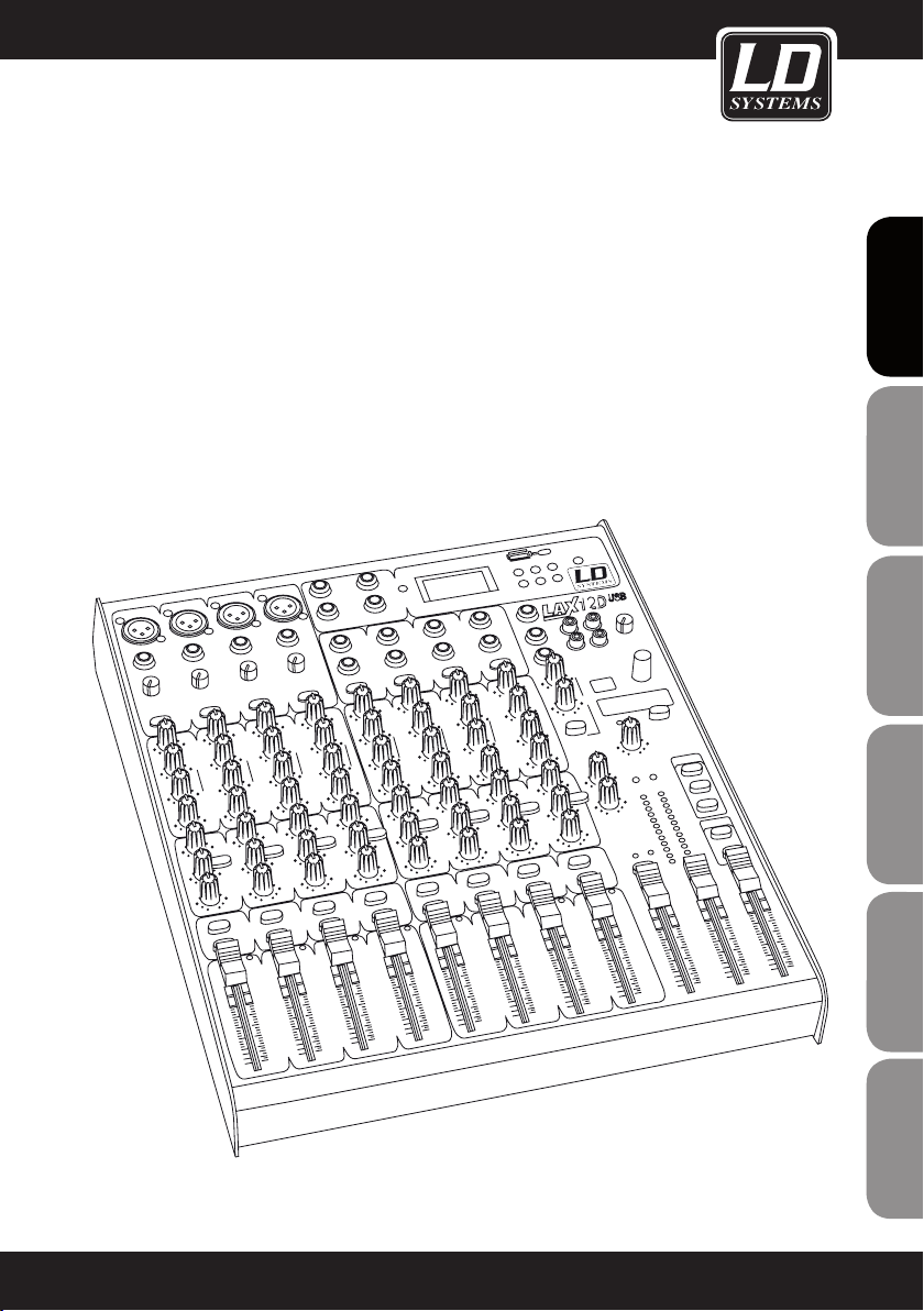
LD LAX12D USB
12 CHANNEL MIXER WITH DSP & USB MP3 PLAYER
Page 2
ENGLISHDEUTSCHFRANCAIS
Thank you for choosing LD-Systems!
We have designed this product to give you reliable operation over many years. Therefore LD-Systems underwrites
high quality products with its name and many years of experience as a producer.
Please, take a few moments to read these instructions carefully, as we want you to enjoy your new LD-Systems
products quickly and to the fullest.
Further information about LD-Systems check our website WWW.LD-SYSTEMS.COM
ESPAÑOLPOLSKIITALIANO
FRANCAISFRANCAIS
FRANCAISFRANCAIS
2
Page 3
LD LAX12D USB
FRANCAIS
FRANCAIS
ENGLISH
12 CHANNEL MIXER WITH DSP & USB MP3 PLAYER
B
S
U
R
E
AY
L
P
C
I
S
U
M
E
L
O
S
N
O
C
G
IN
IX
M
Q
E
Q
E
Q
E
Q
E
Q
E
Q
E
Q
E
Q
E
R
L
R
L
R
L
R
L
R
L
R
L
R
L
R
L
DEUTSCH
FRANCAIS
FRANCAIS
FRANCAIS
ESPAÑOL
POLSKI
ITALIANO
3
Page 4
PREVENTIVE MEASURES:
1. Please read the attached safety instructions as well as the following instructions carefully.
2. Please keep all the instructions.
3. Please use the device only as intended.
4. Please respect the valid waste management rules. Please deliver the packaging divided into plastic and
paper/ cardboard to the recycling management.
ENGLISHDEUTSCHFRANCAIS
5. Please refer all servicing to qualified personel only if the device is damaged, exposed to liquid/rain or if it does
not operate normally.
6. Please, do not expose to any kind of heat such as ovens, radiators, or any other devices (incl. amplifiers).
Please check for enough distance between amplifiers and walls, racks, etc. to prevent overheating.
7. After connection please check the wiring to prevent any kind of accident or damage.
Please never use any kind of damaged cable and wiring.
8. Only use authorized and stable stands, brackets, shelfs, tables etc.. for installations. Please check for
adequate stability against collapse.
9. Appearance of interferences when using wireless systems.
The simultaneous use of wireless microphones and of mobile phones (if both devices are not very distant from
each other) can lead to the appearance of interferences in the microphone signal which can be heard in the
PA system.
CAUTION
RISK OF ELECTRIC SHOCK
CAUTION:
To reduce the risk of electric shock, do not remove cover (or back). No user serviceable parts inside. Refer
servicing to qualified personnel.
The lightning flash with arrowhead symbol within an equilateral triangle is intended to alert the
user to the presence of uninsulated “dangerous voltage” within the product´s enclosure that may be
of sufficient magnitude to constitute a risk to persons.
ESPAÑOLPOLSKIITALIANO
The exclamation mark within an equilateral triangle is intended to alert the user to the presence of
important operating and maintenance (servicing) instructions in the literature accompanying the
appliance.
DO NOT OPEN
CAUTION! HIGH VOLUME!
You will operate this transmission system for professional use. Therefore the commercial use of this equipment
FRANCAISFRANCAIS
FRANCAISFRANCAIS
is liable to the rules and regulations of the Accident Prevention & Insurance Association of your industry sector.
Adam Hall as a manufacturer is bound to inform you formally about the existence of eventual sanitary risks.
This system is able to induce an acoustic pressure of 80 db. 85 db is by law the maximum audio pressure
level which your ear can be exposed to during a work day. It was set according to the technical expertise of the
occupational medicine as a basis for the noise rating level. Higher sound levels or longer exposition times could
damage your ear. The time of exposition by higher sound pressure levels should be shortened in order to prevent
from ear damages. Here are a few reliable warning signals which show that you have exposed yourself for a too
long period to excessive sound pressure levels:
- You hear bell- or whistling sounds!
- You have the impression that you can’t hear high tones anymore!
4
Page 5
FEATURES & GETTING STARTED:
INTRODUCTION
Thank you for choosing this LD Systems audio product. The LAX12D is a professional compact mixer. It's
smooth, natural sound and precise reproduction make it ideal for gigs, recording, and fixed PA installations. The
LAX12D offers some features that are not often found in this price class. The mono channels stand out because
of their ultra-low-noise microphone preamps with +48V phantom power. In addition, all channels are equipped
with warm and natural sounding equalizers: the mono channels have 3-band EQs (MID: with adjustable centre
frequencies), the stereo channels with 4-band EQs with fixed centre frequencies. Moreover, the LAX12D has a
highly precise (12-segment) level meter, 2-track inputs that are assignable to both the main mix outputs and
the phones/control room outputs, and much more. In addition, the integral 24-bit effects processor provides 100
effects presets. The LAX12D mixer is extraordinarily easy to use. Nevertheless, we recommend that you read this
manual carefully before using the product for the first time. This will enable you to get the most out of your mixer.
FEATURES
The LAX12D mixer was developed for professional applications and offers the following features:
• MIC input channels with gold-plated XLR connectors and balanced line inputs
• stereo input channels with balanced TRS jacks
• ultra-low-noise, discrete MIC preamps with +48V phantom power
• High headroom and dynamic range
• mono channels with inserts
• switchable low-cut lter on each mono channel
• +4dBu/-10dBV selector on each stereo channel
• warm and natural sounding 4-band (xed-frequency) EQ on each stereo channel
• 3-band EQ (MID: adjustable centre frequency, 100 Hz – 8 kHz) on each mono channel
• peak LED on each channel
• mute/Alt3-4/solo function on each channel
• 2 AUX returns as additional inputs
• control room and phones outputs
• 2-track inputs assignable to main mix outputs and phones/control room outputs
• highly precise (12-segment) level meter
• integral 24-bit effects processor
• 100 effects presets
• effect bypass function via MUTE switch or footswitch (available optionally, connects to DFX FOOTSWITCH jack)
FRANCAIS
FRANCAIS
ENGLISH
DEUTSCH
FRANCAIS
FRANCAIS
FRANCAIS
ESPAÑOL
POLSKI
ITALIANO
5
Page 6
FEATURES & GETTING STARTED:
• Before plugging in your LAX12D mixer, make certain that the available AC voltage is suitable for your device.
• Make certain that the mixer is turned off before connecting it to the mains power, and set all controls to "zero".
This will avoid damage to your speakers due to loud power-on noise and high levels.
• Always turn on the mixer rst and then the power amplier. When powering down, the sequence is reversed:
ENGLISHDEUTSCHFRANCAIS
First turn off the power amplifier and then the mixer.
• Always turn off the LAX12D mixer before connecting cables.
• Do not use solvents to clean the LAX12D; use a clean, dry cloth. When powering down, the sequence is
reversed: First turn off the power amplifier and then the mixer.
• Always turn off the LAX8D mixer before connecting cables.
• Do not use solvents to clean the LAX8D; use a clean, dry cloth.
ESPAÑOLPOLSKIITALIANO
FRANCAISFRANCAIS
FRANCAISFRANCAIS
6
Page 7
CONTROL ELEMENTS:
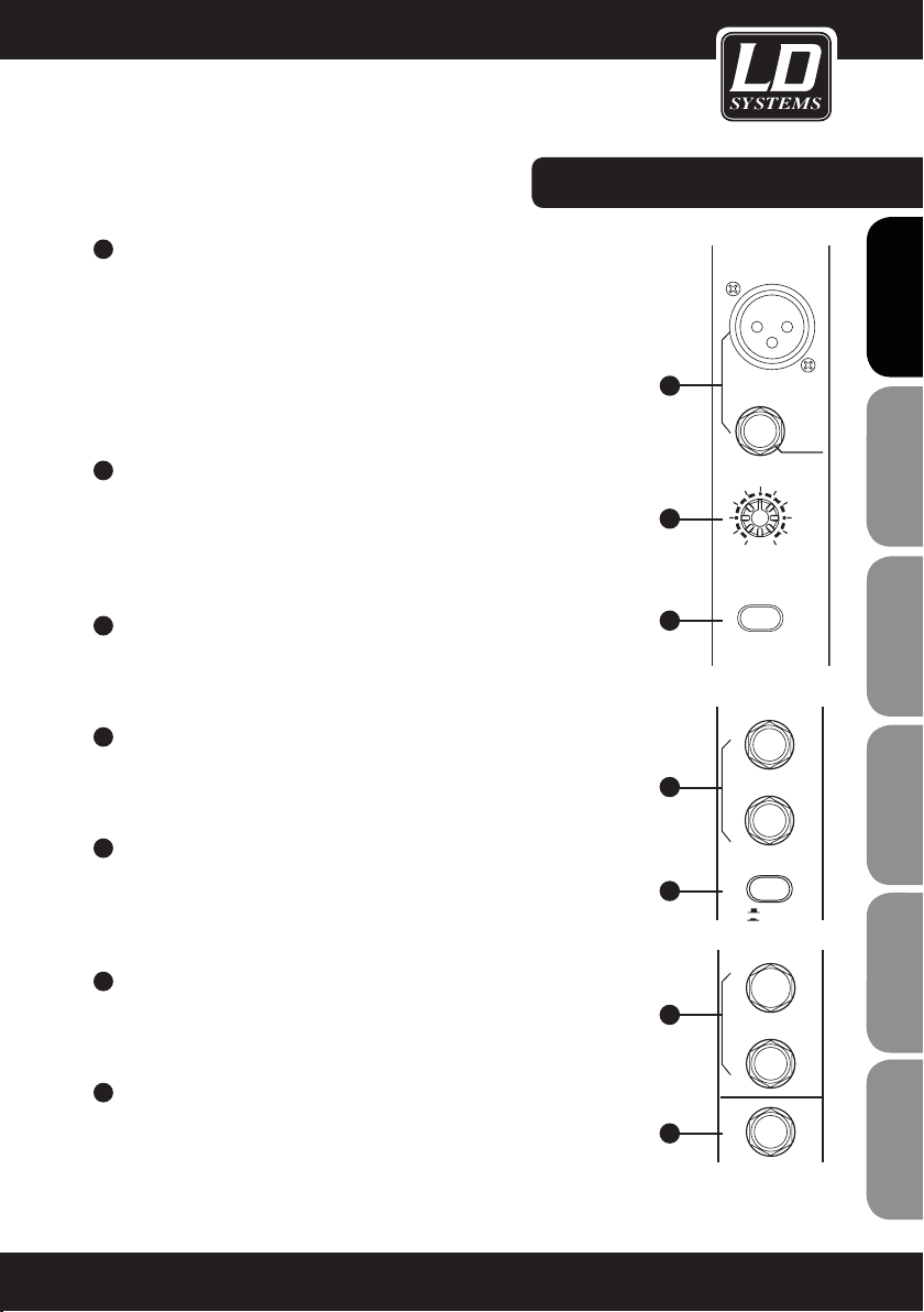
1
MONO CHANNELS (MIC/LINE)
The mono channels offer balanced XLR connectors for low-impedance microphones and other low-level equipment. In addition, there are 6.3 mm TRS jack
input connectors for microphones and line level equipment (e.g., synthesizers,
drum computers, effects processors, etc.). Important: The MIC and LINE inputs
cannot be used simultaneously on the same channel. +48V PHANTOM POWER
The XLR inputs on the mono channels provide +48V phantom power for condenser microphones. Important: Never connect a microphone without phantom
power to the XLR input when phantom power is on.
2
INPUT GAIN ADJUSTMENT
The input gain control has two different scales: one for microphones and one
for line level devices. The outer ring (0 ~ 44 dB) refers to microphones, the
inner one (+15 ~ -30 dB) to line level devices. Always adjust the gain control
so that the peak LED above the channel fader lights up only occasionally. If the
LED is on constantly, this can lead to distortion.
3
LOW CUT FILTER
The LOW CUT button activates a low cut lter (75 Hz, slope 18 dB/octave) for
reducing low-frequency noise such as mains hum or handling noises from
vocal microphones.
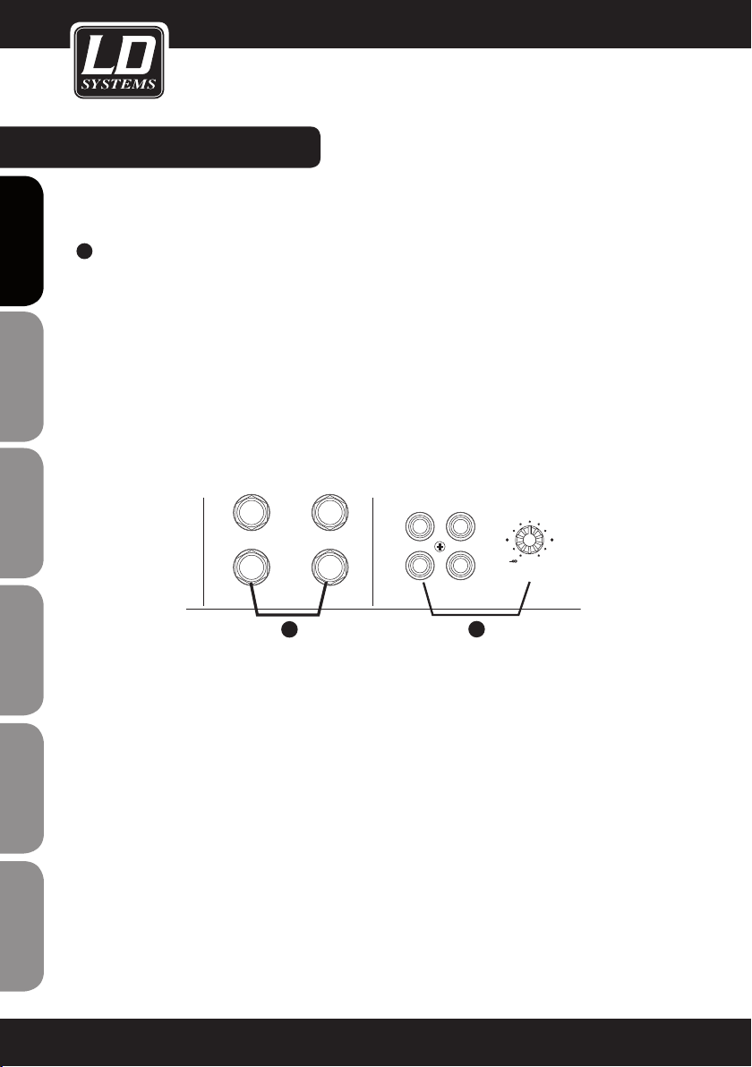
4
STEREO CHANNELS
The stereo channels are configured as stereo pairs with 6.3 mm TRS jack
input connectors. Mono signal sources should be connected to the left jack
input connector.
FRANCAIS
FRANCAIS
MIC 1
1
BAL OR
UNBAL
LINE IN 1
2
LINE
+15dB -25dB
MIC
0dB 40dB
ENGLISH
DEUTSCH
FRANCAIS
FRANCAIS
FRANCAIS
3
LOW CUT
75Hz 18dB/Oct
LINE IN 19/20
ESPAÑOL
4
LEFT(MONO)
5
+4dBu/-10dBV SELECTOR
The line inputs of the stereo channels have a button for selecting the input
sensitivity (+4 dBu for professional audio equipment, -10 dBV for general hi-
devices, etc.). If you are uncertain which setting to use for the respectively
connected device, rst try +4 dBu. If the level is too low, switch to -10 dBv.
6
AUX SENDS
These 6.3 mm TRS sockets can be used to split the signal and send it additionally to external effects processors or the like. In addition, these outputs can
be used as submix outputs.
7
PHONE
Headphones for monitoring the output signal (MAIN MIX) can be connected to
this TRS socket.
RIGHT
5
6
-10dBV
AUX SENDS
1
2
+4dBu
POLSKI
ITALIANO
7
PHONE
7
Page 8
CONTROL ELEMENTS:
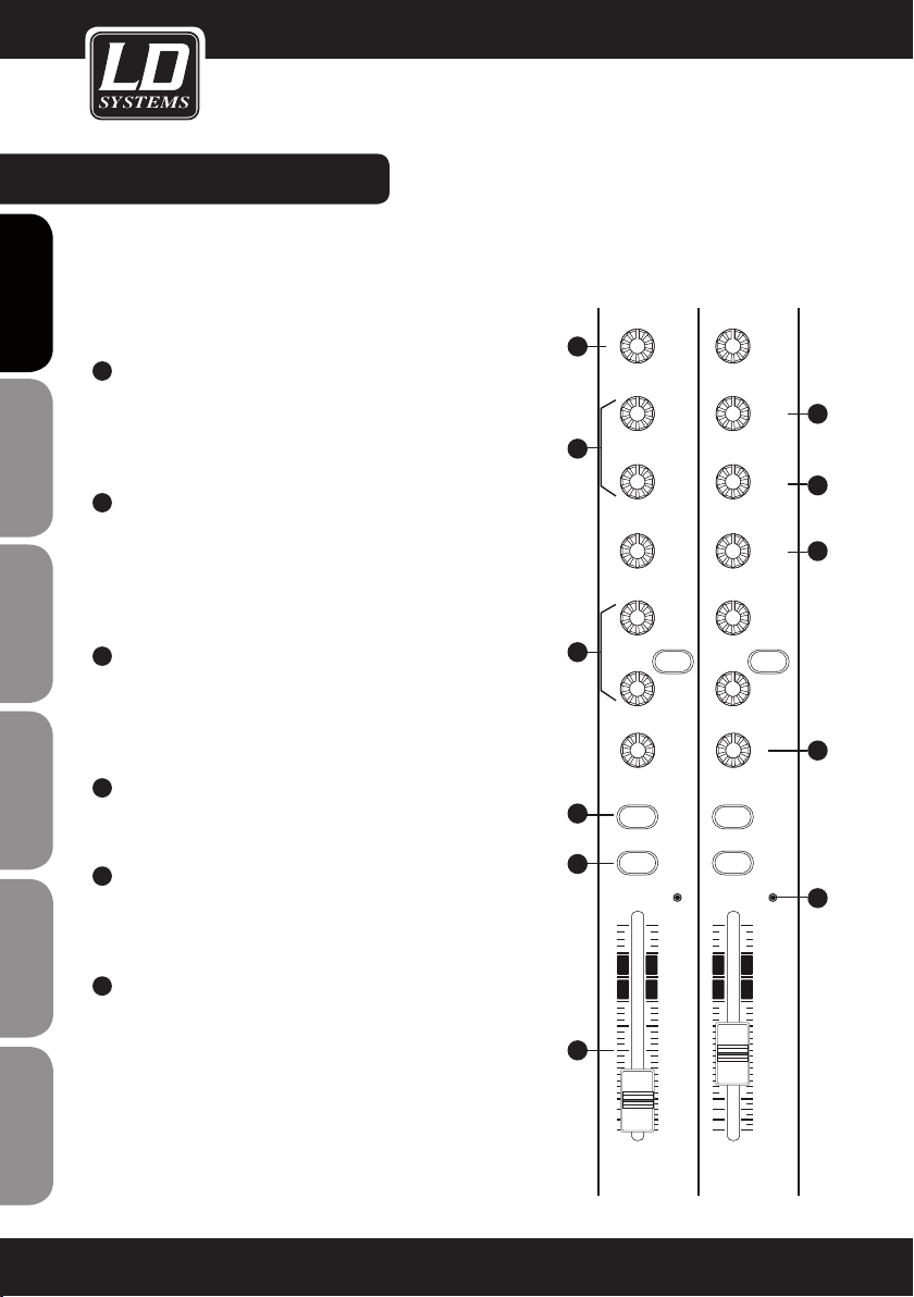
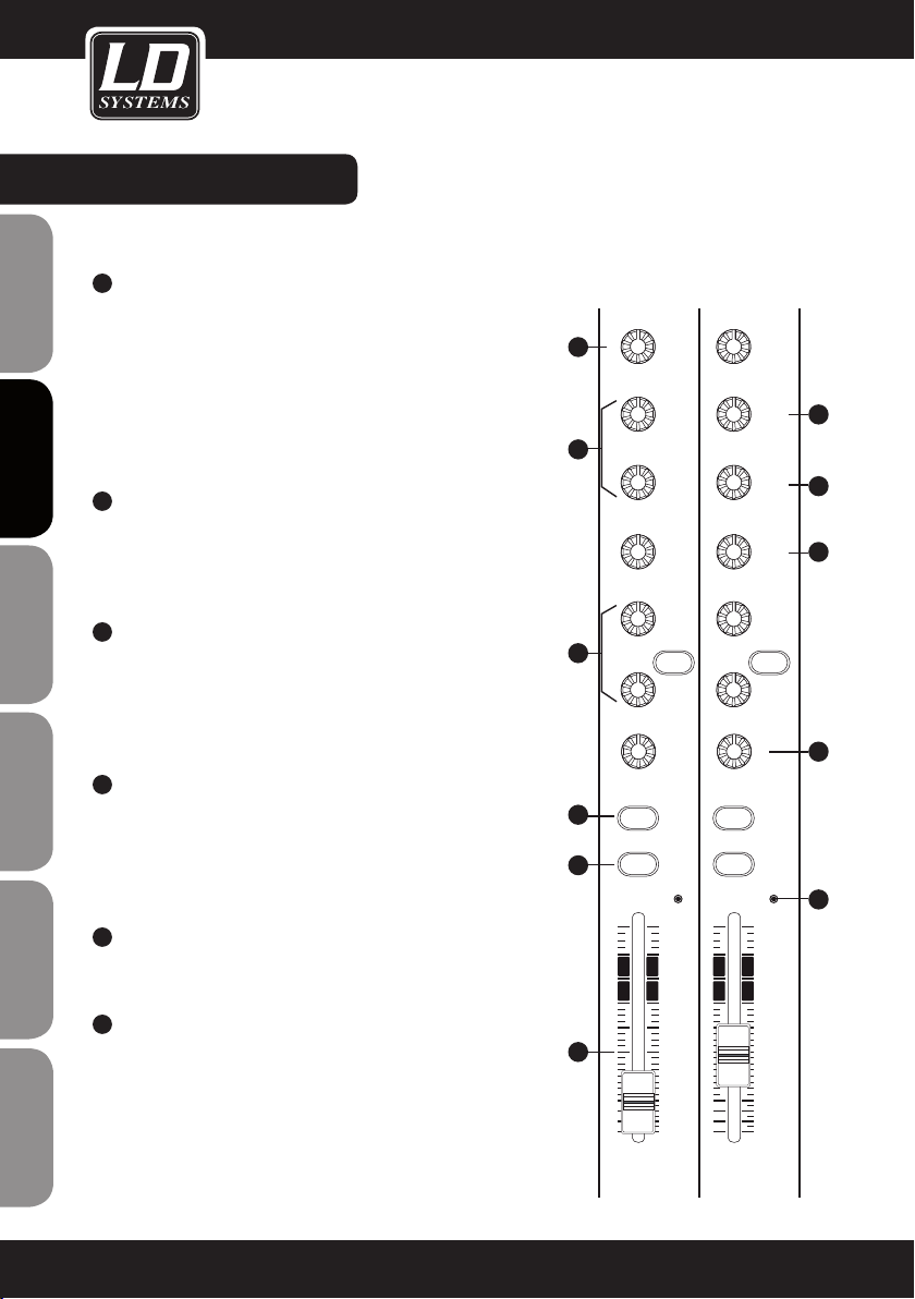
EQUALIZER
The mono input channels of the LAX12D are equipped with 3-band
equalizers (HI/MID/LOW; MID: with adjustable centre frequencies), the
stereo channels with 4-band EQs with fixed centre frequencies (HI,
HI-MID, MID-LOW and LOW). The boost/cut range is +/-15 dB.
ENGLISHDEUTSCHFRANCAIS
8
HI
This knob is used to control the high frequencies. You can use it to
add more brilliance and presence to the corresponding signal or
attenuate undesirably loud high frequencies (boost/cut range -15
dB to +15 dB, centre frequency 12 kHz).
9
MID
This knob is used to control the midrange frequencies. These are
the most important frequencies for musical instruments and the
human voice (boost/cut range -15 dB to +15 dB). The FREQ knob
is used to set the centre frequency that is to be boosted or cut
(100 Hz to 8 kHz).
8
10
9
11
12
10
11
ESPAÑOLPOLSKIITALIANO
12
FRANCAISFRANCAIS
FRANCAISFRANCAIS
13
8
HI-MID
This knob is used to control the hi-mids, which are slightly higher
than the frequencies covered by the MID EQ. This provides even
greater flexibility when it comes to equalization of the important
midrange frequencies.
MID-LOW
This knob is used to control the mid-low frequencies (boost/cut
range -15 dB to +15 dB, centre frequency 500 Hz).
LOW
This knob is used to control the low frequencies. You can use
it, for example, to boost a bass drum, bass guitar or male voice
(boost/cut range -15 dB to +15 dB, centre frequency 80 Hz).
AUX SEND CONTROLS
These two knobs are used to adjust the level of the signals sent
to AUX buses 1 and 2. This does not affect the MAIN MIX output
signal. AUX 1 can be configured as PRE or POST fader using the
PRE/POST button. In the POST position (button not pressed) the
signal is sent after the channel fader, meaning that the volume set
for this channel also affects the AUX 1 signal. In the PRE position
(button pressed), the signal is sent before the fader, so that the
channel fader does not affect the AUX 1 signal. AUX 2 is a "post
fader" path.
13
14
15
16
17
KAEPKAEP
10
dB
5
0
-5
-10
18
-15
-20
-30
-40
-60
OO
10
dB
5
0
-5
-10
-15
-20
-30
-40
-60
O
O
Page 9
CONTROL ELEMENTS:
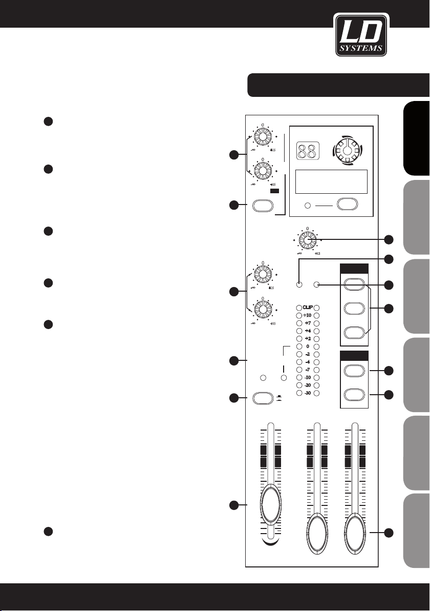
14
PAN/BAL
The mono channels of the LAX12D have panorama (PAN) controls and the stereo channels have balance
(BAL) controls, both of which are used to distribute the signal to the right and left output channels.
15
MUTE/ALT3-4
Each of the channels of the LAX12D has a MUTE/ALT3-4 switch. This switch can be used to send the signal
of the respective channel to the ALT3-4 output.
16
SOLO
The SOLO switch lets you hear only the signal of the channel for which the solo function is activated (button
pressed) without the other channels. The SOLO switch is especially useful for adjusting input levels (gain
adjustment) and as a "preview" option for monitoring the respective signal.
17
PEAK LED
All channels of the LAX12D are equipped with a peak LED for monitoring the respective audio signal. If the
peak LED lights up (6 dB below the actual clipping threshold), this means that the signal is peaking and
distortion may ensue.
18
CHANNEL FADER
This fader controls the overall volume of the respective channel, i.e., the level at which the signal is sent to
the main mix.
19
2-TRACK IN/OUT
TAPE IN: Use the TAPE IN input to connect a tape recorder or DAT recorder. Press the 2TK IN button on the
front panel to send the signal coming from the connected device to the PHONES/CONTROL ROOM output or
the 2TK TO MAIN MIX button to send it to the MAIN MIX output. TAPE OUT: The mix can be output to a tape
recorder via these cinch (RCA) connectors. 2TK IN CONTROL: This control is used to adjust the level of the
2TK IN signal, which can be varied from ∞ to MAX.
FRANCAIS
FRANCAIS
ENGLISH
DEUTSCH
FRANCAIS
FRANCAIS
FRANCAIS
ESPAÑOL
POLSKI
ITALIANO
9
Page 10
CONTROL ELEMENTS:
20
ENGLISHDEUTSCHFRANCAIS
ESPAÑOLPOLSKIITALIANO
STEREO AUX RETURNS
These 6.3 mm jack (TRS) sockets are primarily used to return the audio signal from an external effects processer
to the mixer (MAIN MIX). In addition, these connectors can be used as additional AUX inputs. Note: If no connector
is plugged into Aux Return 2, the signal of the internal effects processor is present on Aux Return 2.
1
LEFT(MONO)
RIGHT
2
STEREO AUX RETURNS
20
RIGHT
2TK IN
LEFT
TAPE IN TAPE OUT
2-TRACK IN/OUT
L
R
19
MAX
FRANCAISFRANCAIS
FRANCAISFRANCAIS
10
Page 11
21
AUX RETURN CONTROL
This control is used to adjust the return levels of AUX
paths 1 & 2, whereby the signals are added to the L/R
MAIN MIX.
22
EFX TO AUX 1
This switch routes the signal that is present at AUX
RETURN 2 to the AUX 1 output so that the effects
can also be heard in the monitor mix - which proves
extraordinarily helpful in practice.
23
AUX SEND CONTROLS
These controls adjust the master AUX SEND level (-∞
to +15 dB). This makes it possible to boost the AUX
signals by up to 15 dB if necessary.
24
LED LEVEL METER
The stereo level meter (12 segments) is used to
monitor the level of the output signal.
25
SOLO MODE BUTTON & SOLO LED [25]
These buttons are used to toggle between the
two solo modes PFL (pre-fader listening, button
not pressed) and AFL (after-fader listening, button
pressed).
In PFL mode, the signals of the channels that have
been switched to SOLO are sent pre fader, i.e., the fader position (channel volume) does not influence the
solo signal. In AFL mode, the signals of the channels
that have been switched to SOLO are sent post fader
plus panorama control – which, although it is above
the channel fader, comes after the fader in terms of
circuitry. In this mode, the position of the channel
fader and the panorama control also influences the
solo signal. Note: The SOLO mode selection (PFL/AFL)
does not have any affect until at least one channel
has been switched to solo mode. In this case, the
SOLO ACTIVE LED is also illuminated.
26
ALT3-4 FADERS
These faders are used to control the level of the ALT
output (control range -∞ to +10 dB).
CONTROL ELEMENTS:
0
1
8
-
+15
AUX RTN 1
21
8
-
AUX RTN 2
0
22
EFX TO AUX 1
0
1
8
-
23
0
2
8
-
AUX SENDS
24
SOLO
ACTIVE
25
SOLO MODE
26
+15
+15
DFX
+15
LEVEL
2
SET
10
dB
-5
-10
-15
-20
-30
-40
-60
ALT 3-4
PFL
AFL
5
0
8 8
FUNCTION
00-09 Echo
10-19 Echo +Verb
20-29 Tremolo
30-39 Plate
40-49 Chorus
PEAK/MUTE
0
8
-
+15
PHONES
CONTROL ROOM
PWRPHANTOM
CLIP
+10
+7
+4
+2
0
-2
-4
-7
-10
-20
-30
LR
OUTPUT LEVEL
MAIN MIX
LEVEL
10
dB
5
0
-5
-10
-15
-20
-30
-40
-60
LEFT
PROGRAM (PUSH)
50-59 Vocal
60-69 Rotary
70-79 Small Room
80-89 Flange+Verb
90-99 Large Hall
DFX MUTE
CTR ROOM
SOURCE
MAIN MIX
ALT 3-4
2TK IN
ASSIGN
TO MIX
ALT 3-4
FRANCAIS
FRANCAIS
ENGLISH
DEUTSCH
FRANCAIS
FRANCAIS
33
32
FRANCAIS
31
30
ESPAÑOL
29
RIGHT
28
10
dB
5
0
-5
-10
-15
-20
-30
-40
-60
POLSKI
ITALIANO
27
2TK
11
Page 12
CONTROL ELEMENTS:
27
MAIN MIX LEVEL
These two faders are used to control the level of the signals sent to the L/R MAIN MIX and TAPE OUT outputs.
ENGLISHDEUTSCHFRANCAIS
28
TK TO MAIN MIX
When this button is pressed, the 2-TRACK IN signal is sent to the MAIN MIX output.
29
ALT3-4 TO MAIN MIX
When this button is pressed, the ALT3-4 signal is sent to the MAIN MIX output and added to the output signal.
30
CONTROL ROOM SOURCE
These buttons are used to determine which signal is heard via the monitor speakers or headphones: MAIN
MIX, ALT 3-4, 2TK IN. Please note that these buttons are inactive in solo mode. If the selected signal cannot
be heard after the CONTROL ROOM SOURCE buttons are pushed, please first check whether the solo mode
has been activated in one of the channels.
31
PWR LED (POWER)
This LED indicates that the mixer is on.
32
PHANTOM LED
This LED indicates that phantom power has been activated.
33
PHONE/CONTROL ROOM
This control is used to adjust the level of the signal sent to the PHONE/CONTROL ROOM output.
ESPAÑOLPOLSKIITALIANO
FRANCAISFRANCAIS
FRANCAISFRANCAIS
12
Page 13
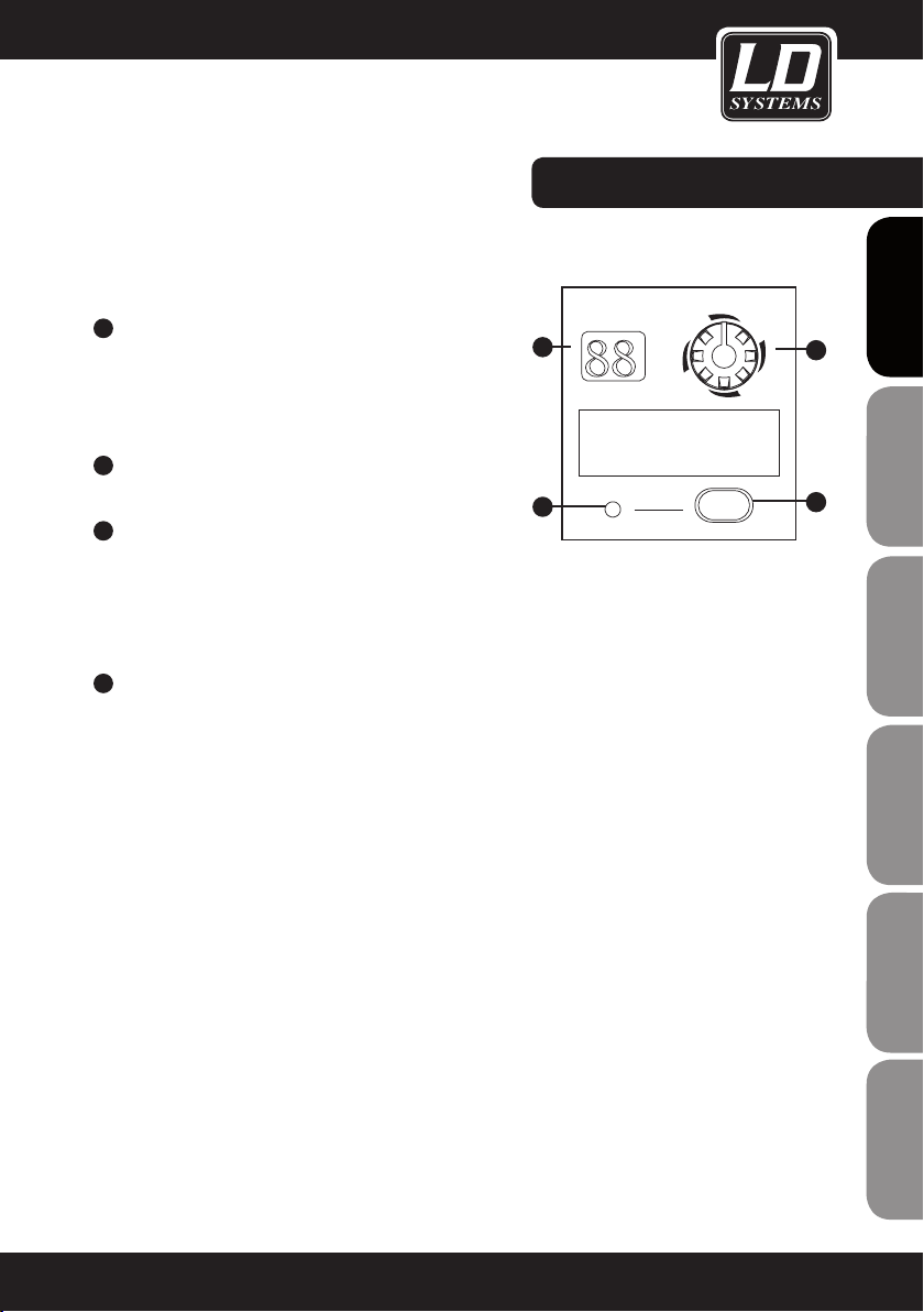
DIGITAL 24-BIT EFFECTS PROCESSOR
34
DFX MUTE SWITCH
This switch is used to activate/deactivate the effects
module. If necessary, this function can also be controlled
conveniently using a footswitch connected to the FOOT
SW socket.
35
DISPLAY
The selected preset is displayed here.
36
PRESET SELECTOR
This knob is used to select the desired effects preset.
There is a total of 100 presets available: Echo, vocal, plate and versatile two-effect combinations. Once you have
selected the desired preset, press the knob to confirm
your selection.
37
PEAK LED
This LED lights up when the input signal reaches the
clipping threshold. When the digital effects module is
deactivated, this LED is illuminated constantly.
CONTROL ELEMENTS:
PROGRAM (PUSH)
35
88
FUNCTION
37
00-09 Echo
10-19 Echo +Verb
20-29 Tremolo
30-39 Plate
40-49 Chorus
PEAK/MUTE
50-59 Vocal
60-69 Rotary
70-79 Small Room
80-89 Flange+Verb
90-99 Large Hall
DFX MUTE
FRANCAIS
FRANCAIS
ENGLISH
36
DEUTSCH
FRANCAIS
FRANCAIS
34
FRANCAIS
ESPAÑOL
POLSKI
ITALIANO
13
Page 14
BACK PANEL:
44 42
PHAN TOM
ENGLISHDEUTSCHFRANCAIS
ON OFF
POWER
43 45 41 40 39 38
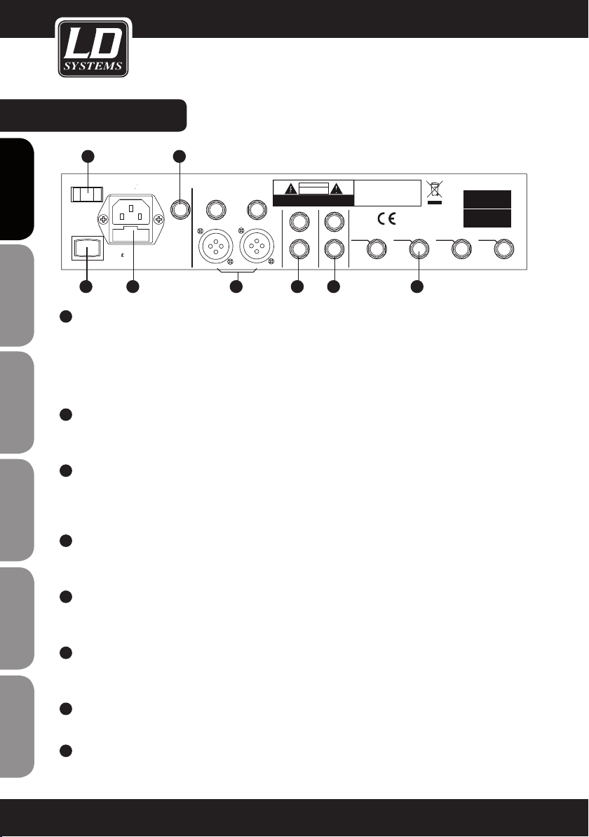
38
INSERTS (MONO CHANNELS)
All mono MIC channels are additionally equipped with Insert sockets (stereo jack, TRS), via which external
effects devices or the like can be patched into the respective channel. The signal is sent immediately after
the input gain control (TRIM) to an external signal processor, for example, a compressor or limiter. Once the
signal has passed through the external signal processor, it is returned to the same channel immediately
before the EQ. Note: Connecting external devices to insert points requires a so-called "Y" cable.
39
CTRL ROOM OUTPUT
These 6.3 mm sockets are used to send the signal to studio monitor speakers (CONTROL ROOM) or a PA
system.
40
ALT OUTPUT
These unbalanced 6.3 mm sockets serve as additional outputs. Their level is controlled using the ALT 3-4
fader in the master section of the mixer (max. +22 dBu). The signals of all channels for which the Mute/Alt
3-4 button has been pushed are routed to this bus; they no longer reach the main mix.
ESPAÑOLPOLSKIITALIANO
41
MAIN MIX OUTPUT
The L/R MAIN MIX OUTPUT has both XLR and 6.3 mm TRS sockets via which the main mix output signal can
be sent to an amplier. The output level is controlled by the MAIN MIX LEVEL fader (-∞ to +10 dB).
Apparaten skall anslutas
till jordat uttag nar den
ansluts till ett natverk
EUROPE
AC INPUT
Fuse:T250mAL
£
210-240V 50Hz
RATED POWER CONSUMPTION: 23W
FOOT SW
RIGHT
MAIN MIX OUTPUT(BAL/UNBAL)
RIGHT
LEFT
LEFT
WARNING: SHOCK HAZARD
AVIS: RISQUE DE CHOC ELECTRIQUE
CAUTION
RISK OF ELECTRIC SHOCK
OUTPUT
DO NOT OPEN
L
R
CAUTION:
REPLACE WITH THE SAME TYPE FUSE AND RATING
- DO NOT OPEN
DISCONNECT SUPPLY CORD BEFORE CHANGING FUSE
- NE PAS OUVRIR
LEFT(3)
INSERT
RIGHT(4)
ALT OUTPUTCTRL ROOM
INSERT
MODEL
SERIAL
3 4
2
INSERT
INSERT
1
42
FRANCAISFRANCAIS
FRANCAISFRANCAIS
43
44
45
14
FOOT SW
This socket can be used to connect an external footswitch for activation/deactivation of the integral effects
processor (function identical with that of the DFX MUTE switch).
PHANTOM SWITCH
This switch activates the +48V phantom power for the four XLR microphone inputs. Important: Make certain
that the phantom power is off before connecting microphones.
POWER SWITCH
This switch is used to turn the mixer ON or OFF.
AC INPUT
This socket is used to connect the power adapter.
Page 15

INSTALLATION AND CONNECTION:
INSTALLATION AND CONNECTION
Now that you have familiarized yourself with the functions of the LAX12D mixer, you should have no trouble
using it. Nevertheless, we recommend that you read the following section carefully. It contains important information about how to obtain the best results with your mixer.
-Before connecting mics or instruments, make certain that the channel and MAIN MIX faders of the LAX12D
mixer are set to minimum (all the way down).
- Make certain that all external devices such as mics, power amplifiers, speakers, effects processors, etc. are
connected properly.
- When running cables, take care not to injure anyone or damage the equipment.
- Set the output level of your mixer and the connected power amplifier to no more than 75%.
- Do not set the PHONE/CONTROL ROOM level higher than 50%.
- Set the EQ controls (HI, MID, LOW) to the middle position.
- Set the PAN/BAL controls to the middle position.
- While speaking into each connected mic (speech or vocals) or playing the instrument, adjust each channel
fader (LEVEL) so that the peak LED of the corresponding channel comes on only occasionally. This will ensure
that there is always enough headroom and dynamic range available.
- You can shape the sound of the individual signals using the respective channel equalizer.
- Repeat this sequence of steps for all of the input channels being used, always keeping an eye on the LED level
meter (OUTPUT LEVEL) so that it does not swing too far into the red area.
FRANCAIS
FRANCAIS
ENGLISH
DEUTSCH
FRANCAIS
FRANCAIS
FRANCAIS
AUDIO CONNECTIONS
The LAX12D mixer offers numerous, highly flexible possibilities for balanced or unbalanced connection of your
equipment via XLR and 6.3 mm TRS connectors. These are explained below.
WIRING CONFIGURATION
The XLR and 6.3 mm TRS connectors of the LAX12D permit balanced and unbalanced connections depending on
the equipment connected. Examples for wiring your system:
ESPAÑOL
POLSKI
ITALIANO
15
Page 16
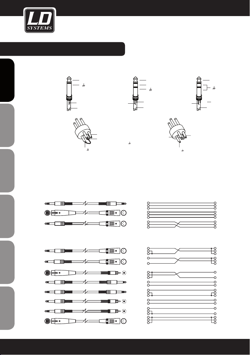
WIRING CONFIGURATION:
BALANCED
Ring
+
-
Tip
Sleeve
Ring
Pin3 (-)
Pin1 ( )
FOR 6.3 MM
ENGLISHDEUTSCHFRANCAIS
TRS PLUGS
FOR XLR
CONNECTORS
UNBALANCED
Tip
Sleeve
+
Pin1 ( )
UNBALANCED
Pin2 (+)
Pin3 (-)
(Linked to Pin1 manually, )
IN-LINE CONNECTION
The mixer provides 6.3 mm stereo and XLR connectors for in-line connection of most professional audio equipment. Configuration examples for the respective connections are provided below.
Tip
Sleeve
Sleeve
Ring
1
2
3
Tip
Ring
ESPAÑOLPOLSKIITALIANO
TIPRINGSLEEVE
1
3
2
BALANCED
TIPRINGSLEEVE
SLEEVERING TIP
1
3
2
1 2
3
UNBALANCED
BALANCED
Pin2 (+)
+
Tip
Sleeve
Tip
Ring
Sleeve
1
2
3
1
2
3
FRANCAISFRANCAIS
FRANCAISFRANCAIS
16
TIPRINGSLEEVE
TIPSLEEVE
3
2 1
TIPSLEEVE
TIPRINGSLEEVE
UNBALANCED
TIPSLEEVE
TIPRINGSLEEVE
3
2 1
SLEEVETIP
SLEEVERINGTIP
Sleeve
Sleeve
Sleeve
Sleeve
Sleeve
Sleeve
Tip
Ring
Tip
1
2
3
Tip
Tip
Ring
Tip
Tip
Ring
1
2
3
1
3
2
1 2
3
1
3
2
1
2
3
1
2
3
Cent er
Screen
Tip
Sleeve
Tip
Ring
Sleeve
Cent er
Screen
Centre
Screen
1
2
3
Page 17

WIRING CONFIGURATION / PRESET
LIST:
INSERT CONNECTION
When connecting external signal processors via the main insert on the mixer, one TRS cable is required for each
send/return. The conguration of this so-called "Y" cable is depicted below.
FOR 6.3 MM STEREO PLUGS (TRS INSERT)
INSERT CABLE
Send
Sleeve
Sleeve
Sleeve
Tip
Ring
Tip
Ring
Tip
Ring
Ring
Return
Tip
Sleeve
TIP RING SLEEVE
TIP RING SLEEVE
TIP RING SLEEVE
SLEEVE TIP
SLEEVE RING TIP
12
3
2
3
1
NO. PRESET DESCRIPTION PARAMETER
00-09 Echo The input signal is sent to the output with a time delay Delay time: 145 - 205 ms
10-19 Echo+Verb Echo with room effect (hall) Delay time: 208 - 650 ms
Decay time: 1.7 - 2.1 s
20-29 Tremolo Amplitude modulation of the signal Rate: 0.6 Hz - 5 Hz
30-39 Plate Hall effect: Simulation of the classic plate vocal effect
Decay time: 0.9 s ~ 3.6 s
(adds brightness)
40-49 Chorus Creates the illusion of multiple instruments (voices) on the basis of a
Rate: 0.92 Hz ~ 1.72 Hz
single signal
50-59 Vocal Hall effect: Simulation of a small room with a short decay time Rev. decay time: 0.8 ~ 0.9 s
Pre-delay: 0 - 45 ms
60-69 Rotary Simulation of typical rotary speaker effect incl. bass box Modulation depth :
20% ~ 80%
70-79 Small room Hall effect: Simulation of a bright studio room effect Decay time: 0.7 ~ 2.1 s
Pre-delay : 20 - 45 ms
80-89 Flanger + Verb Combination of a modulated delay effect plus hall Decay time: 1.5 ~ 2.9 s
Rate : 0.8 Hz ~ 2.52 Hz
90-99 Large hall Hall effect: Simulation of a large room Pre-delay : 23 ~ 55 ms
Tip (Send)
Sleeve
Tip (Return)
Sleeve
1
2 (Send)
3
1
2 (Return)
3
Centre (Send)
Screen
Centre (Return)
Screen
FRANCAIS
FRANCAIS
ENGLISH
DEUTSCH
FRANCAIS
FRANCAIS
FRANCAIS
ESPAÑOL
POLSKI
ITALIANO
17
Page 18
SPECIFICATIONS:
MONO CHANNELS
Microphone input: electronically balanced, separate
inputs
Frequency range: 10 Hz … 45 kHz, +/-3 dB
ENGLISHDEUTSCHFRANCAIS
THD+N: 0.005% @ +4 dBu, 1 kHz
Gain: 0 dB … 40 dB (MIC)
Signal-to-noise ratio: 102 dB
Line input: electronically balanced
Frequency range: 10 Hz … 45 kHz, +/-3 dB
THD+N: 0.005% @ +4 dBu, 1 kHz
Gain: +15 dBu … -25 dBu (LINE)
STEREO CHANNELS
Line input: unbalanced
Frequency range: 10 Hz … 45 kHz, +/-3 dB
THD+N: 0.005% @ +4 dBu, 1 kHz
IMPEDANCE
Microphone input: 3.6 kohm
All other inputs: 10 kohms or higher
Tape out: 1 kohm
All other outputs: 120 ohms
EQUALIZER
Treble (shelving):+/-15 dB @ 12 kHz
Midrange (bell, mono channels): +/-15 dB @ 100 Hz
… 8 kHz
ESPAÑOLPOLSKIITALIANO
High midrange (stereo channels): +/-15 dB @ 3 kHz
Low midrange (stereo channels): +/-15 dB @ 500 Hz
Bass (shelving): +/-15 dB @ 80 Hz
Low cut filter: 75 Hz, 18 dB/oct.
MAIN MIX SECTION
Noise (bus noise): Fader 0 dB, channels muted: -100 dBr
(ref.: +4 dBu)
Fader 0 dB, all input channels activated (unity gain): -90
dBr (ref.: +4 dBu)
Max output level: +22 dBu (XLR, balanced); +22 dBu
(6.3-mm jack, unbalanced)
AUX returns, gain: OFF … +15 dB
AUX sends, max. output level: +22 dBu
POWER SUPPLY
(AC adapter)
Mains voltage:
USA/Canada 100 – 120 V, ~60 Hz
Europe 210 – 230 V, ~50 Hz
Great Britain/Australia 240 V, ~50 Hz
Power consumption: 12-channel mixer: 30 W
PHYSICAL SPECIFICATIONS
Dimensions (WxDxH):
12-channel mixer: 315 x 436 x 86 mm
Weight:
12-channel mixer: 5.1 kg without adapter
Subject to technical modifications without prior notice,
because all of our products are tested and improved
continually.
DSP EFFECTS SECTION
A/D and D/A converters: 24-bit
FRANCAISFRANCAIS
FRANCAISFRANCAIS
DSP resolution: 24-bit
Effect types: Echo, echo+ reverb, tremolo, plate, chorus,
vocal, rotary, small room, flanger + reverb, large hall
No. of presets: 100
Switches: Preset selector switch, effect bypass
18
Page 19
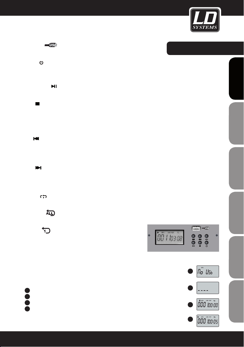
USB PORT
For USB memory sticks only
MP3 PLAYER:
POWER
To power on the USB-MP3 player keep the power button pressed for 3 seconds. Same procedure to power it off.
Once the player is on, it is automatically set to the "pause" mode.
PLAY / PAUSE
Press this button during playback to pause the playback. Press again to start the playback again.
STOP
Press this button during playback to stop the playback. The display will now show how many tracks are available
on the USB memory stick. When the playback has been stopped press PRE/NEXT to go the previous/next track
or press the STOP button again to go to the beginning of the first track. Press the PLAY/PAUSE button to start the
playback again.
PRE
Pressing this button while in pause mode will take you to the previous track. The pause mode remains ON. Press
the PLAY/PAUSE button to start the playback again. Pressing this button during playback will take you to the
previous track and play it.
NEXT
Pressing this button while on pause mode will take you to the next track. The pause mode remains ON. Press
the PLAY/PAUSE button to start the playback again. Pressing this button during playback will take you to the next
track and play it.
REPEAT
Press this button to choose between the four following repeat modes:
1. REP ALL
Repeat all tracks available on the memory stick. Display shows:
2. REP 1
Repeat one track. Display shows
3. PLAY IN ORDER
Plays the tracks selected previously. No display indication
MUSIC PLAY ER
FRANCAIS
FRANCAIS
ENGLISH
DEUTSCH
FRANCAIS
FRANCAIS
FRANCAIS
ESPAÑOL
POLSKI
4. RANDOM PLAY
Plays all tracks in a random order. Display shows: A
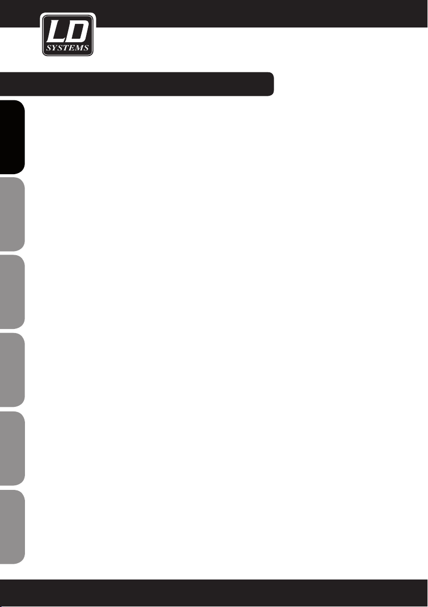
IMPORTANT:
A
Display when no USB memory stick is connected:
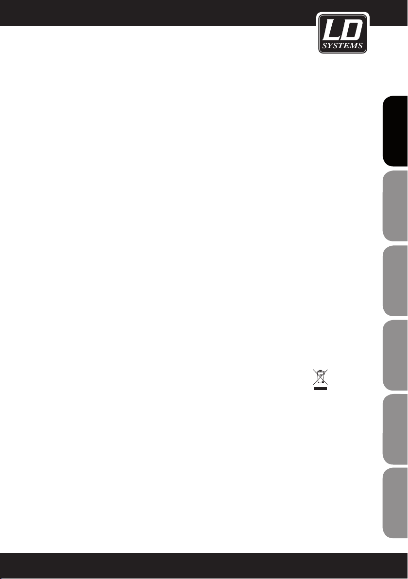
B
Display when the player scans your USB memory stick for MP3 music files:
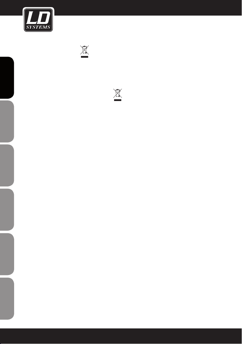
C
Display when the player is in pause mode:
D
Display when the player is on:
A
B
C
D
ITALIANO
19
Page 20
MANUFACTURER´S DECLARATIONS:
LIMITED WARRANTY
This Limited Warranty applies to the Adam Hall, LD Systems, Defender, Palmer and Eminence branded products.
ENGLISHDEUTSCHFRANCAIS
The statutory warranty rights towards the seller are not affected by this guarantee. In fact, it justifies, additional
independent warranty claims towards Adam Hall.
Adam Hall warrants that the Adam Hall product you have purchased from Adam Hall or from an Adam Hall authorized reseller is free from defects in materials or workmanship under normal use for a period of 2 or 5 years from
the date of purchase.
The Limited Warranty Period starts on the date of purchase. In order to receive warranty services you are required
to provide proof of the purchase date. Your dated sales or delivery receipt, showing the date of purchase, is your
proof of the purchase date. Should products of the brands named above be in need of repair within the limited warranty period, you are entitled to warranty services according to the terms and conditions stated in this document.
This Limited Warranty extends only to the original purchaser of this Adam Hall branded product and is not transferable to anyone who obtains ownership of the Adam Hall branded product from the original purchaser. During
the Limited Warranty Period, Adam Hall will repair or replace the defective component parts or the product. All
component parts or hardware products removed under this Limited Warranty become the property of Adam Hall.
In the unlikely event that your Adam Hall product has a recurring failure, Adam Hall, at its discretion, may elect to
provide you with a replacement unit of Adam Hall´s choice that is at least equivalent to your Adam Hall branded
product in hardware performance.
Adam Hall does not warrant that the operation of this product will be uninterrupted or error-free. Adam Hall is not
responsible for damage that occurs as a result of your failure to follow the instructions included with the Adam
ESPAÑOLPOLSKIITALIANO
Hall branded product.
This Limited Warranty does not apply,
- to wear parts (e.g. accumulator)
- to any product from which the serial number has been removed or that has been damaged or rendered defec
tive as the result of an accident
- in case of, misuse, abuse, or other external causes
FRANCAISFRANCAIS
FRANCAISFRANCAIS
- by operation outside the usage parameters stated in the user´s documentation shipped with the
product
- by use of spare parts not manufactured or sold by Adam Hall
- by modification or service by anyone other than Adam Hall
These terms and conditions constitute the complete and exclusive warranty agreement between you and Adam
Hall regarding the Adam Hall branded product you have purchased.
20
Page 21
LIMITATION OF LIABILITY
If your Adam Hall branded hardware product fails to work as warranted above, your sole and exclusive remedy
shall be repair or replacement. Adam Halls’ maximum liability under this limited warranty is expressly limited
to the lesser of the price you have paid for the product or the cost of repair or replacement of any hardware
components that malfunction in conditions of normal use.
Adam Hall is not liable for any damages caused by the product or the failure of the product, including any lost
profits or savings or special, incidental, or consequential damages. Adam Hall is not liable for any claim made by
a third party or made by you for a third party.
This limitation of liability applies whether damages are sought, or claims are made, under this Limited Warranty
or as a tort claim (including negligence and strict product liability), a contract claim, or any other claim. This limitation of liability cannot be waived or amended by any person. This limitation of liability will be effective even if
you have advised Adam Hall of an authorized representative of Adam Hall of the possibility of any such damages.
This limitation of liability however, will not apply to claims for personal injury.
This Limited Warranty gives you specific legal rights. You may also have other rights that may vary from state to
state or from country to country. You are advised to consult applicable state or country laws for a full determination of your rights.
REQUESTING WARRANTY-SERVICE
To request warranty service for the product, contact Adam Hall or the Adam Hall authorized reseller from which
you purchased the product.
FRANCAIS
FRANCAIS
ENGLISH
DEUTSCH
FRANCAIS
FRANCAIS
FRANCAIS
EG-DECLARATION OF CONFIRMITY
These products meet the essential requirements as well as the further standards of the EU Directives 199/5/EU,
89/336/EU.
CORRECT DISPOSAL OF THIS PRODUCT (ELECTRICAL WASTE)
(Applicable in the European Union and other European countries with separate collection systems)
This marking shown on the product or its literature, indicates that it should not be disposed with other household
wastes at the end of its working life. To prevent possible harm to the environment or human health from uncontrolled waste disposal, please separate this from other types of wastes and recycle it responsibly to promote the
sustainable reuse of material resources.
Household users should contact either the retailer where they purchased this product, or their local government
office, for details on where and how they can recycle this item in an enviromentally friendly manner.
Business users should contact their supplier and check the terms and conditions of the purchase contract. This
product should not be mixed with other commercial wastes for disposal
ESPAÑOL
POLSKI
ITALIANO
21
Page 22
WEEE-DECLARATION
Your LD-Systems product was developed and manufactured with high quality materials and components wich
can be recycled and/or reused. This symbol indicates that electrical and electronic equipment must be disposed
of separately from normal waste at the end of its operational lifetime.
Please dispose of this product by bringing it to your local collection point or recycling centre for such equipment.
This will help to protect the environment in which we all live.
ENGLISHDEUTSCHFRANCAIS
BATTERIES AND ACCUMULATORS
The supplied batteries or rechargeable batteries can be recycled. Please dispose of them as special waste or return
them to your specialist dealer. In order to protect the environment, only dispose exhausted batteries.
NOTES:
ESPAÑOLPOLSKIITALIANO
FRANCAISFRANCAIS
FRANCAISFRANCAIS
Adam Hall GmbH, all rights reserved. The technical data and the functional product characteristics can be subject
to modifications. The photocopying, the translation, and all other forms of copying of fragments or of the integrality of this user’s manual is prohibited.
22
Page 23
NOTES:
NOTES:
FRANCAIS
FRANCAIS
ENGLISH
DEUTSCH
FRANCAIS
FRANCAIS
FRANCAIS
ESPAÑOL
POLSKI
ITALIANO
23
Page 24
ENGLISHDEUTSCHFRANCAIS
Sie haben die richtige Wahl getroffen!
Diese LD-Systems Produkte werden Sie lange Jahre durch Zuverlässigkeit, Wirtschaftlichkeit und einfaches
Handling überzeugen. Dafür garantiert LD-Systems mit seinem Namen und seiner in vielen Jahren erworbenen
Kompetenz als Hersteller hochwertiger Geräte.
Nehmen Sie sich nun ein paar Minuten Zeit, diese Anleitung zu lesen. Wir möchten, dass Sie einfach
und schnell in den Genuss dieser Technik kommen.
Mehr Informationen zu LD-SYSTEMS finden Sie auf unserer Internetseite WWW.LD-SYSTEMS.COM
ESPAÑOLPOLSKIITALIANO
FRANCAISFRANCAIS
FRANCAISFRANCAIS
24
Page 25

LD LAX12D USB
FRANCAIS
FRANCAIS
ENGLISH
12 CHANNEL MIXER WITH DSP & USB MP3 PLAYER
B
S
U
R
E
AY
L
P
C
I
S
U
M
E
L
O
S
N
O
C
G
IN
IX
M
Q
E
Q
E
Q
E
Q
E
Q
E
Q
E
Q
E
Q
E
R
L
R
L
R
L
R
L
R
L
R
L
R
L
R
L
DEUTSCH
FRANCAIS
FRANCAIS
FRANCAIS
ESPAÑOL
POLSKI
ITALIANO
25
Page 26
VORSICHTSMASSNAHMEN:
1. Bitte beachten Sie die Sicherheitshinweise und studieren Sie diese Anleitung sorgfältig.
2. Bewahren Sie alle Hinweise und Anleitungen sicher auf.
3. Verwenden Sie das Gerät nur in der vorgesehenen Art und Weise.
ENGLISHDEUTSCHFRANCAIS
4. Beachten Sie die in Ihrem Land geltenden Entsorgungsgesetze. Trennen Sie bei der Entsorgung bitte Plastik
und Papier bzw. Kartonagen von einander.
5. Sollte Ihr Gerät nicht mehr ordnungsgemäß funktionieren, Flüssigkeiten ausgesetzt worden oder auf sonstige Art
und Weise beschädigt sein, überlassen Sie bitte jegliche Reparaturen ausschließlich autorisiertem Fachpersonal.
6. Halten Sie das Gerät von Hitzequellen wie z.B. Ofen, Heizkörper, oder sonstige Quellen (auch Verstärker) fern.
Sorgen Sie dafür dass das Gerät immer so installiert ist, dass es ausreichend gekühlt wird und nicht überhitzt.
7. Überprüfen Sie alle Verbindungen nach dem Sie das Gerät angeschlossen haben, um Schäden oder Unfälle zu
vermeiden.
8. Verwenden Sie ausschließlich stabile und passende Stative bzw. Befestigungen, wenn das Gerät fest installiert
wird. Stellen Sie sicher, dass das Gerät sicher installiert ist und nicht herunterfallen kann.
CAUTION
RISK OF ELECTRIC SHOCK
DO NOT OPEN
ACHTUNG:
Entfernen Sie niemals die Abdeckung, da sonst die Gefahr eines elektrischen Schocks besteht.
Im Inneren des Gerätes benden sich keine Teile, die vom Bediener gewartet oder repariert werden können.
Lassen Sie Reparaturen ausschließlich von qualifiziertem Servicepersonal durchführen.
Dieses Symbol warnt vor nichtisolierten, gefährlichen Spannungen im Geräteinneren, die einen
ESPAÑOLPOLSKIITALIANO
gefährlichen Schlag verursachen können.
Dieses Symbol kennzeichnet wichtige Bedienungs- und Wartungshinweise.
Vorsicht! Hohe Lautstärke!
Diese Übertragungsanlage wird von Ihnen professionell eingesetzt. Daher unterliegt der Gebrauch bei gewerbli-
FRANCAISFRANCAIS
FRANCAISFRANCAIS
cher Nutzung den Regeln und Vorschriften der zuständigen Berufsgenossenschaft. Adam Hall als Hersteller ist
daher verpflichtet, Sie auf möglicherweise bestehende gesundheitliche Risiken ausdrücklich hinzuweisen.
26
Page 27
FUNKTIONEN & ERSTE SCHRITTE:
EINFÜHRUNG
Wir freuen uns, dass Sie sich für ein Audioprodukt von LD Systems entschieden haben.
Der Mixer LAX12DUSB ist ein Kompaktmischer für den professionellen Einsatz, mit angenehmem, natürlichem
Klang und präziser Wiedergabe – ideal für Live-Auftritte, Aufnahmen und als festinstallierter PA-Mischer. Dabei
bietet der LAX12DUSB einige Features, die in dieser Preisklasse nicht selbstverständlich sind.
Die Mono-Kanalzüge zeichnen sich durch außerordentlich rauscharme Mikrofon-Preamps mit +48- VoltPhantomspeisung aus. Darüber hinaus sind alle Kanalzüge mit warm und natürlich klingenden Equalizern
ausgestattet: die Mono-Kanalzüge mit 3-Band-EQs (MID: mit regelbaren Mittenfrequenzen) die Stereo-Kanalzüge
mit 4-Band-EQs mit festen Mittenfrequenzen. Außerdem verfügt der LAX12DUSB über eine hochpräzise Aus-
steuerungsanzeige (12 Segmente), 2-Track-Eingänge, die sowohl auf die Summenausgänge als auch auf die
Kopfhörer/Regie-Ausgänge geroutet werden können, und vieles mehr.
Zusätzlich stellt der integrierte 24-Bit-Effektprozessor 100 Effekt-Presets bereit.
Der LAX12DUSB-Mixer ist außerordentlich einfach zu bedienen. Dennoch empfehlen wir, diese Anleitung vor
Inbetriebnahme sorgfältig zu lesen, damit Sie wirklich das Optimum aus Ihrem Mixer herausholen.
FEATURES
Der LAX12DUSB-Mixer wurde für den professionellen Einsatz entwickelt und bietet folgende Ausstattung:
• Mikrofonkanäle mit vergoldeten XLR-Anschlüssen und symmetrischen Line-Eingängen
• Stereo-Kanalzüge mit symmetrischen Klinkeneingängen (TRS)
• Rauscharme, diskrete Mikrofon-Preamps mit +48-Volt-Phantomspeisung
• Hohe Aussteuerungsreserve und Dynamik
• Mono-Kanalzüge mit Inserts
• Schaltbare Trittschall lter in allen Mono-Kanalzügen
• +4dBu/-10dBV-Umschaltung in allen Stereo-Kanalzügen
• Warm und natürlich klingende 4-Band-Equalizer (feste Mittenfrequenzen) in den Stereo-Kanalzügen
• 3-Band-Equalizer (MID: regelbare Mittenfrequenz, 100 Hz – 8 kHz) in den Mono-Kanalzügen
• Peak-LEDs in allen Kanalzügen
• Mute/Alt3-4/Solo-Funktion in allen Kanalzügen
• 2 AUX-Returns als zusätzliche Eingänge
• Regie- und Kopfhörer-Ausgänge
• 2-Track-Eingänge mit Routing-Möglichkeiten auf Summen-, Regie- und Kopfhörer-Ausgänge
• Hochpräzise Aussteuerungsanzeige (12 Segmente)
• Integrierter digitaler 24-Bit-Effektprozessor
• 100 Effekt-Presets
• Effekt-Bypass-Funktion über MUTE-Taste oder Fußschalter (optional erhältlich, Anschluss an DFX FOOTSWITCH-Buchse)
FRANCAIS
FRANCAIS
ENGLISH
DEUTSCH
FRANCAIS
FRANCAIS
FRANCAIS
ESPAÑOL
POLSKI
ITALIANO
27
Page 28
FUNKTIONEN & ERSTE SCHRITTE:
• Überprüfen Sie vor Anschluss Ihres LAX12DUSB-Mixers, dass die Stromversorgung mit der für das Gerät geeigneten
Netzspannung erfolgt.
• Vergewissern Sie sich, dass der Mixer ausgeschaltet ist, bevor Sie ihn an das Stromnetz anschließen, und stellen Sie
alle Regler in “Null”-Stellung. Auf diese Weise vermeiden Sie Schäden an Ihren Lautsprechern durch laute
ENGLISHDEUTSCHFRANCAIS
Einschaltgeräusche und hohe Pegel.
• Schalten Sie immer zuerst den Mixer und danach den angeschlossenen Leistungsverstärker ein.´Beim Ausschalten gilt
die umgekehrte Reihenfolge: Schalten Sie zuerst den Leistungsverstärker und danach den Mixer aus.
• Schalten Sie den LAX12DUSB-Mixer stets aus, bevor Sie Verkabelungen vornehmen.
• Verwenden Sie zur Reinigung des LAX12DUSB keine Lösungsmittel, sondern ein sauberes, trockenes Tuch.
ein. Beim Ausschalten gilt die umgekehrte Reihenfolge: Schalten Sie zuerst den Leistungsverstärker und danach den
Mixer aus.
• Schalten Sie den LAX12DUSB-Mixer stets aus, bevor Sie Verkabelungen vornehmen.
• Verwenden Sie zur Reinigung des LAX12DUSB keine Lösungsmittel, sondern ein sauberes, trockenes Tuch.
ESPAÑOLPOLSKIITALIANO
FRANCAISFRANCAIS
FRANCAISFRANCAIS
28
Page 29

1
DIE MONOKANÄLE (MIC/LINE)
Die Mono-Kanalzüge bieten symmetrische XLR-Anschlüsse für niederohmige
Mikrofone und anderes Equipment mit niedrigem Pegel.
Zusätzlich stehen 6,3-mm-Klinkeneingänge für den Anschluss von Mikrofonen
und Geräten mit Line-Pegel (z.B. Synthesizer, Drum-Computer, Effektprozessoren etc.) zur Verfügung.
Achtung: Es ist nicht möglich, MIC- und LINE-Eingänge desselben Kanals
gleichzeitig zu belegen.
+48-VOLT-PHANTOMSPEISUNG
Die XLR-Eingänge der Mono-Kanalzüge stellen +48-Volt-Phantomspannung
zur Speisung von Kondensatormikrofonen bereit. Achtung:
Schließen Sie bei eingeschalteter Phantomspeisung niemals Mikrofone ohne
Phantomspeisung an die XLR-Eingänge an.
2
EINSTELLEN DER EINGANGSVERSTÄRKUNG
Der Gain-Regler verfügt über zwei unterschiedliche Einteilungen: eine für
Mikrofone und eine für Geräte mit Line-Pegel. Der äußere Ring (0 ~ 44 dB)
bezieht sich auf Mikrofone, der innere (+15 ~ -30 dB) auf Geräte mit Line-
Pegel. Stellen Sie den Gain-Regler stets so ein, dass die Peak-LED oberhalb
des Kanal-Faders nur gelegentlich aufleuchtet. Leuchtet die LED konstant,
kann dies zu Verzerrungen führen.
3
TRITTSCHALLFILTER (LOW CUT)
Die LOW CUT-Taste aktiviert ein Trittschall lter (75 Hz, Flankensteilheit 18 dB/
Oktave) zur Reduzierung von tieffrequenten Störgeräuschen wie Netzbrummen
oder Handgeräusche von Vokalmikrofonen.
BEDIENELEMENTE:
MIC 1
1
BAL OR
UNBAL
LINE IN 1
2
LINE
+15dB -25dB
MIC
0dB 40dB
3
4
LOW CUT
75Hz 18dB/Oct
LINE IN 19/20
LEFT(MONO)
FRANCAIS
FRANCAIS
ENGLISH
DEUTSCH
FRANCAIS
FRANCAIS
FRANCAIS
ESPAÑOL
4
DIE STEREOKANÄLE
Die Stereo-Kanalzüge sind jeweils als Stereopaare mit 6,3-mm-Klinkeneingängen
(TRS) ausgeführt. Mono-Signalquellen schließen Sie an den linken Klinkeneingang
an.
5
+4dBu/-10dBV-UMSCHALTUNG
Die Line-Eingänge der Stereo-Kanalzüge verfügen über eine Taste zur
Umschaltung der Eingangsemp ndlichkeit (+4 dBu für professionelles AudioEquipment, -10 dBV für HiFi-Geräte etc.). Falls Sie nicht sicher sind, welche
Einstellung für das jeweils angeschlossene Gerät geeignet ist, versuchen Sie
es zuerst mit +4 dBu. Sollte der Pegel nicht hoch genug sein, schalten Sie auf
-10 dBV um.
6
AUX SENDS
Über diese 6,3-mm-Klinkenbuchsen kann das Signal gesplittet und zusätzlich
an externe Effektprozessoren o.Ä. überführt werden. Darüber hinaus bieten
sich diese Ausgänge als Submix-Ausgänge an.
RIGHT
5
6
-10dBV
AUX SENDS
1
2
+4dBu
POLSKI
ITALIANO
7
PHONE
29
Page 30
BEDIENELEMENTE:
7
PHONE
An diese Klinkenbuchse schließen Sie den Kopfhörer zur Überwa-
ENGLISHDEUTSCHFRANCAIS
ESPAÑOLPOLSKIITALIANO
FRANCAISFRANCAIS
FRANCAISFRANCAIS
chung des Ausgangssignals (MAIN MIX) an.
EQUALIZER
Die Mono-Kanalzüge des LAX12D sind 3-Band-Equalizern (HI/
MID/LOW; MID: mit regelbaren Mittenfrequenzen), die StereoKanalzüge mit 4-Band-EQs mit festen Mittenfrequenzen (HI, HI-
MID, MID-LOW und LOW) ausgestattet. Der Regelbereich beträgt
jeweils +/-15 dB.
8
HI
Über diesen Regler steuern Sie die hohen Frequenzen, d.h. Sie
können dem entsprechenden Signal mehr Brillanz und Präsenz
verleihen oder unerwünscht laute hohe Frequenzen absenken
(Regelbereich -15 dB bis +15 dB, Mittenfrequenz 12 kHz).
9
MID
Über diesen Regler steuern Sie die mittleren Frequenzen, die
wichtigsten Frequenzen für Musikinstrumente und die menschli-
che Stimme (Regelbereich -15 dB bis +15 dB).
Über den zugehörigen FREQ-Regler bestimmen Sie die anzuhebende bzw. abzusenkende Mittenfrequenz (100 Hz bis 8 kHz).
10
HI-MID
Über diesen Regler steuern Sie die Hochmitten, die etwas
oberhalb der Frequenzen des MID-EQs liegen. Diese Einstellungsmöglichkeit
bietet noch mehr Flexibilität bei der detaillierten Entzerrung der
wichtigen mittleren Frequenzen.
11
MID-LOW
Über diesen Regler steuern Sie die Tiefmitten (Regelbereich -15
dB bis +15 dB, Mittenfrequenz 500 Hz).
12
LOW
Über diesen Regler steuern Sie die tiefen Frequenzen, d.h. Sie
können z.B. einer Bassdrum, Bassgitarre oder männlichen Stimme
mehr Fundament verleihen (Regelbereich -15 dB bis +15 dB,
Mittenfrequenz 80 Hz).
8
10
9
11
12
13
14
15
16
17
KAEPKAEP
10
dB
5
0
-5
-10
18
-15
-20
-30
-40
-60
OO
10
dB
5
0
-5
-10
-15
-20
-30
-40
-60
O
O
30
Page 31

BEDIENELEMENTE:
13
AUX SEND-REGLER
Über diese beiden Regler steuern Sie die an die AUXWege (Ausspielwege) 1 und 2 gesendeten Signale. Das
Summensignal (MAIN MIX) bleibt unbeeinflusst. AUX 1 kann über die PRE/POST-Taste PRE- oder POST-Fader
geschaltet werden. In Position POST (Taste nicht gedrückt) erfolgt der Signalabgriff nach dem Kanal-Fader,
so dass sich die für diesen Kanalzug eingestellte Lautstärke auch auf das AUX 1-Signal auswirkt. In Position
PRE (Taste gedrückt) erfolgt der Signalabgriff vor dem Fader, das AUX 1-Signal bleibt also vom Kanal-Fader
unbeein usst. Bei AUX 2 handelt es sich um einen “Post-Fader”-Weg.
14
PAN/BAL
Die Mono-Kanalzüge des LAX12D verfügen über einen Panorama-Regler (PAN), die Stereo-Kanalzüge über
einen so genannten Balance-Regler (BAL), die beide der Verteilung des Signals auf den rechten und linken
Ausgangskanal dienen.
15
MUTE/ALT3-4
Sämtliche Kanalzüge des LAX12D verfügen über eine MUTE/ALT3-4-Taste, über die Sie das Signal des
jeweiligen Kanals auf den ALT3-4-Ausgang routen können.
16
SOLO
Die SOLO-Taste bewirkt, dass Sie ausschließlich das Signal des Kanalzugs hören, dessen Solo-Funktion
aktiviert ist (Taste gedrückt), ohne die anderen Kanäle. Besonders hilfreich ist die SOLOTaste beim Einpegeln
(Gain-Einstellung) und als “Preview”-Option zur Überwachung des jeweiligen Signals.
FRANCAIS
FRANCAIS
ENGLISH
DEUTSCH
FRANCAIS
FRANCAIS
FRANCAIS
ESPAÑOL
POLSKI
ITALIANO
31
Page 32

BEDIENELEMENTE:
17
PEAK-LED
Alle Kanalzüge des LAX12D sind mit einer Peak-LED zur Überwachung des jeweiligen Audiosignals ausge-
stattet. Wenn die Peak-LED au euchtet (6 dB unterhalb der tatsächlichen Übersteuerungsgrenze), bedeutet
ENGLISHDEUTSCHFRANCAIS
dies, dass das Signal die maximal mögliche Aussteuerung erreicht hat und Verzerrungen entstehen können.
18
KANAL-FADER
Über diesen Fader steuern Sie die Gesamtlautstärke des jeweiligen Kanalzugs, d.h. den Pegel, der an die
Summenausgänge (MAIN MIX) ausgegeben wird.
19
2-TRACK IN/OUT
TAPE IN: Am Tape-In-Eingang können Sie ein Tonbandgerät oder einen DAT-Recorder anschließen. Drücken
Sie die Taste 2TK IN an der Vorderseite, um das Signal des angeschlossenen Geräts auf den Ausgang
PHONES/CONTROL ROOM zu routen, oder die Taste 2TK TO MAIN MIX, um es über den Ausgang MAIN MIX
auszugeben.
TAPE OUT: Über diese Cinch-Buchsen kann der Mix an ein Tonbandgerät ausgegeben werden.
REGLER 2TK IN: Mit diesem Regler können Sie den Signalpegel am Eingang 2TK IN im Bereich zwischen - ∞
und MAX einstellen.
20
ESPAÑOLPOLSKIITALIANO
FRANCAISFRANCAIS
FRANCAISFRANCAIS
STEREO AUX RETURNS
Diese 6,3-mm-Klinkenbuchsen (TRS) dienen in erster Line dazu, das Audiosignal aus einem externen
Effektprozessor zurück in den Mixer (MAIN MIX) zu überführen. Darüber hinaus lassen sich diese Buchsen als
zusätzliche AUX-Eingänge nutzen. Hinweis. Solange kein Stecker im Aux Return 2 steckt, liegt am Aux Return
2 das Signal des internen Effektprozessors an.
1
LEFT(MONO)
RIGHT
2
STEREO AUX RETURNS
20
RIGHT
2TK IN
LEFT
TAPE IN TAPE OUT
2-TRACK IN/OUT
L
R
19
MAX
32
Page 33

21
REGLER AUX RETURN
Über diese Regler steuern Sie die Return-Pegel der
AUX-Wege 1&2, wobei die Signale dem Summenausgang L/R (MAIN MIX) hinzugemischt werden.
22
EFX TO AUX 1
Über diesen Schalter routen Sie das an AUX RETURN 2
anliegende Signal auf den AUX 1-Ausgang, so dass der
Effekt auch im Monitor-Mix zu hören ist – was sich in
der Praxis als außerordentlich hilfreich erweist.
23
AUX SEND-REGLER
Über diese Regler steuern Sie die Master-AUX SEND-
Pegel (-∞ bis +15 dB). Auf diese Weise lassen sich
die AUX-Signale bei Bedarf um bis zu 15 dB anheben.
24
LED-PEGELANZEIGE
Über die Stereo-Pegelanzeige (12 Segmente) überwachen Sie den Pegel des Ausgangssignals.
25
SOLO MODE-TASTE & SOLO-LED-ANZEIGE
Über diese Taste schalten Sie zwischen den beiden Solo-Modi PFL (Pre-Fader Listening, Taste nicht gedrückt)
und AFL (After-Fader Listening, Taste gedrückt) um.
Im PFL-Modus werden die Signale der SOLO geschalteten Kanalzüge vor dem Fader abgegriffen, d.h.
die Fader-Stellung (Kanallautstärke) beeinfl usst das
Solo-Signal nicht. Im AFL-Modus werden die Signale
der SOLO geschalteten Kanalzüge nach dem Fader
plus Panorama-Regler – der sich zwar oberhalb des
Kanal-Faders befi ndet, schaltungstechnisch aber
nach dem Fader angeordnet ist – abgegriffen.
In diesem Modus beeinfl usst die Einstellung des
Kanal-Faders und des Panorama-Reglers also auch
das Solo-Signal.
Hinweis: Die SOLO MODE-Umschaltung (PFL/AFL)
wirkt sich erst dann aus, wenn mindestens ein
Kanalzug in den Solo-Modus geschaltet ist. In diesem
Fall leuchtet auch die SOLO ACTIVE-LED.
26
ALT3-4-FADER
Über diesen Fader steuern Sie den Pegel des ALT-
Ausgangs (Regelbereich -∞ bis +10 dB).
BEDIENELEMENTE:
FRANCAIS
FRANCAIS
33
32
31
30
29
28
27
ENGLISH
DEUTSCH
FRANCAIS
FRANCAIS
FRANCAIS
ESPAÑOL
POLSKI
ITALIANO
0
1
8
-
21
22
23
24
25
26
AUX RTN 1
0
8
-
AUX RTN 2
EFX TO AUX 1
0
1
8
-
0
2
8
-
AUX SENDS
SOLO
ACTIVE
SOLO MODE
+15
+15
+15
DFX
+15
LEVEL
2
SET
10
dB
-5
-10
-15
-20
-30
-40
-60
ALT 3-4
PFL
AFL
5
0
8 8
00-09 Echo
10-19 Echo +Verb
20-29 Tremolo
30-39 Plate
40-49 Chorus
PEAK/MUTE
-
PHONES
CONTROL ROOM
LR
OUTPUT LEVEL
8
CLIP
+10
0
+7
+4
+2
0
-2
-4
-7
-10
-20
-30
FUNCTION
+15
PWRPHANTOM
PROGRAM (PUSH)
50-59 Vocal
60-69 Rotary
70-79 Small Room
80-89 Flange+Verb
90-99 Large Hall
MAIN MIX
LEVEL
10
dB
5
0
-5
-10
-15
-20
-30
-40
-60
LEFT
DFX MUTE
CTR ROOM
SOURCE
MAIN MIX
ALT 3-4
2TK IN
ASSIGN
TO MIX
ALT 3-4
2TK
RIGHT
10
dB
5
0
-5
-10
-15
-20
-30
-40
-60
33
Page 34

BEDIENELEMENTE:
27
MAIN MIX LEVEL
Über diese beiden Fader steuern Sie den Pegel des an die Summenausgänge L/R (MAIN MIX) und den
Recording-Ausgang (TAPE OUT) überführten Signals.
ENGLISHDEUTSCHFRANCAIS
28
TK TO MAIN MIX
Bei gedrückter Taste wird das 2-TRACK IN-Signal auf den Summenausgang (MAIN MIX) geroutet.
29
ALT3-4 TO MAIN MIX
Bei gedrückter Taste wird das ALT3-4-Signal auf den Summenausgang (MAIN MIX) geroutet und dem Ausgangssignal hinzugemischt.
30
CONTROL ROOM SOURCE
Über diese Tasten legen Sie fest, welches Signal Sie über Ihre Monitor-Lautsprecher oder Kopfhörer hören:
MAIN MIX, ALT 3-4, 2TK IN. Bitte beachten Sie, dass diese Tasten im Solo-Modus nicht aktiv sind. Sollte nach
Drücken der CONTROL ROOM SOURCE-Tasten also nicht das gewählte Signal zu hören sein, vergewissern
Sie sich bitte zunächst, ob der Solo-Modus in einem der Kanalzüge aktiviert wurde.
31
PWR-LED (POWER)
Diese LED zeigt an, dass der Mixer eingeschaltet ist.
32
PHANTOM-LED
Diese LED zeigt an, dass die Phantomspeisung aktiviert wurde.
33
PHONE/CONTROL ROOM
Über diesen Regler steuern Sie den Pegel des an die Regie (CONTROL ROOM) und den Kopfhörer-Ausgang
ESPAÑOLPOLSKIITALIANO
(PHONE) überführten Signals.
FRANCAISFRANCAIS
FRANCAISFRANCAIS
34
Page 35

DIGITALER 24 BIT-EFFEKTPROZESSOR
34
TASTE DFX MUTE
Mit dieser Taste aktivieren bzw. deaktivieren Sie das
Effekt-Modul. Bei Bedarf können Sie diese Funktion auch
bequem über einen Fußschalter an der Buchse FOOT SW
bedienen.
35
DISPLAY
Hier wird das gewählte Preset angezeigt.
36
PRESET-WAHLSCHALTER
Mit diesem Regler wählen Sie das gewünschte
Effekt-Preset aus. Insgesamt stehen 100 Presets zur
Auswahl: Echo, Vocal, Plate sowie vielseitige Kombinationen aus zwei Effekten. Wenn Sie das gewünschte Preset
angewählt haben, drücken Sie den Regler, um Ihre
Auswahl zu bestätigen.
BEDIENELEMENTE:
PROGRAM (PUSH)
35
88
FUNCTION
37
00-09 Echo
10-19 Echo +Verb
20-29 Tremolo
30-39 Plate
40-49 Chorus
PEAK/MUTE
50-59 Vocal
60-69 Rotary
70-79 Small Room
80-89 Flange+Verb
90-99 Large Hall
DFX MUTE
FRANCAIS
FRANCAIS
ENGLISH
36
DEUTSCH
FRANCAIS
FRANCAIS
34
FRANCAIS
37
PEAK-LED
Diese LED leuchtet auf, wenn das Eingangssignal die
Übersteuerungsgrenze erreicht. Wenn das digitale
Effekt-Modul deaktiviert wird, leuchtet diese LED dauerhaft.
ESPAÑOL
POLSKI
ITALIANO
35
Page 36

RÜCKSEITE:
ENGLISHDEUTSCHFRANCAIS
38
39
40
ESPAÑOLPOLSKIITALIANO
44 42
Apparaten skall anslutas
PHAN TOM
ON OFF
POWER
till jordat uttag nar den
ansluts till ett natverk
EUROPE
AC INPUT
Fuse:T250mAL
£
210-240V 50Hz
RATED POWER CONSUMPTION: 23W
FOOT SW
RIGHT
MAIN MIX OUTPUT(BAL/UNBAL)
RIGHT
LEFT
LEFT
CAUTION
RISK OF ELECTRIC SHOCK
DO NOT OPEN
WARNING: SHOCK HAZARD
AVIS: RISQUE DE CHOC ELECTRIQUE
- DO NOT OPEN
DISCONNECT SUPPLY CORD BEFORE CHANGING FUSE
L
LEFT(3)
R
RIGHT(4)
OUTPUT
ALT OUTPUTCTRL ROOM
CAUTION:
REPLACE WITH THE SAME TYPE FUSE AND RATING
- NE PAS OUVRIR
INSERT
INSERT
MODEL
SERIAL
3 4
2
INSERT
INSERT
43 45 41 40 39 38
INSERTS (MONOKANÄLE)
Alle Mono-MIC-Kanäle sind zusätzlich mit Insert-Buchsen (Stereoklinke, TRS) ausgestattet, über
die Sie externe Effektgeräte o.Ä. in den jeweiligen Kanalzug einschleifen können. Dabei wird das
Signal unmittelbar nach dem Gain-Regler (TRIM) abgegriffen und an einen externen Signalprozessor,
z.B. einen Kompressor oder Limiter, überführt. Nachdem es diesen durchlaufen hat, wird es
vor dem EQ in denselben Kanalzug zurückgeführt. Hinweis: Für den Anschluss externer Geräte an
Insert-Punkte benötigen Sie so genannte “Y”-Kabel
CTRL ROOM OUTPUT
Über diese 6,3-mm-Klinkenbuchsen geben Sie das Signal an Studio-Monitorlautsprecher (CONTROL
ROOM) oder ein PA-System aus.
ALT OUTPUT
Diese unsymmetrischen 6,3-mm-Klinkenbuchsen dienen als zusätzliche Ausgänge, deren Pegel
über den ALT 3-4-Fader im Master-Bereich des Mixers gesteuert wird (max. +22 dBu). Die Signale
aller Kanäle bei denen die Mute/Alt 3-4 Taste gedrückt ist, werden auf diesen diesen Bus geroutet,
sie gelangen nicht mehr an den Main Mix.
1
41
FRANCAISFRANCAIS
FRANCAISFRANCAIS
42
43
36
MAIN MIX OUTPUT
Die Summenausgänge L/R (MAIN MIX OUTPUT) sind sowohl als XLR- als auch als 6,3-mm-Klinkenausgänge
(TRS) ausgeführt, über die Sie das Haupt-Ausgangssignal an einen Leistungsverstärker
überführen können. Die Steuerung des Ausgangspegels erfolgt über die MAIN MIX LEVEL-Fader
(-∞ bis +10 dB).
FOOT SW
An diese Klinkenbuchse können Sie einen externen Fußschalter zur Aktivierung/Deaktivierung des
integrierten Effektprozessors anschließen (identische Funktion wie die DFX MUTE-Taste).
PHANTOM-SCHALTER
Mit diesem Schalter aktivieren Sie die +48-Volt-Phantomspeisung für die vier XLR-Mikrofoneingänge.
Achtung: Vergewissern Sie sich, dass die Phantomspeisung abgeschaltet ist, bevor Sie Mikrofone
anschließen.
Page 37

INSTALLATION UND VERKABELUNG:
44
POWER-SCHALTER
Mit diesem Schalter schalten Sie den Mixer ein (ON) oder aus (OFF).
45
NETZBUCHSE (AC INPUT)
An diese Buchse schließen Sie den Netzadapter an.
FRANCAIS
FRANCAIS
ENGLISH
INSTALLATION UND VERKABELUNG
Nachdem Sie sich mit den Funktionen des LAX12D-Mixers vertraut gemacht haben, sollte die Bedienung kein
Problem darstellen. Dennoch empfehlen wir Ihnen, das folgende Kapitel genau zu lesen, da es zahlreiche nützliche Hinweise für den optimalen Umgang mit Ihrem Mixer enthält.
• Vergewissern Sie sich vor dem Anschluss von Mikrofonen und Instrumenten, dass die Kanal- und MAIN MIXFader des LAX12D-Mixers auf Minimum (nach unten) gestellt sind.
• Achten Sie darauf, dass alle externen Komponenten wie Mikrofone, Leistungsverstärker, Lautsprecher, Effektprozessoren etc. korrekt angeschlossen sind.
• Lassen Sie bei der Verlegung der Kabel Sorgfalt walten, damit niemand verletzt oder das Equipment beschädigt wird.
• Stellen Sie den Ausgangspegel Ihres Mixers und des angeschlossenen Leistungsverstärkers nicht höher als 75% ein.
• Stellen Sie den PHONE/CONTROL ROOM-Pegel nicht höher als 50% ein.
• Stellen Sie die EQ-Regler (HI, MID, LOW) in Mittelposition.
• Stellen Sie die Panorama- bzw. Balance-Regler (PAN/BAL) in Mittelposition.
• Stellen Sie die Kanal-Fader (LEVEL) ein, während Sie das jeweils angeschlossene Mikrofon ansprechen (Spra-
che oder Gesang) bzw. das Instrument spielen, und achten Sie darauf, das die Peak-LED des entsprechenden
Kanals nur gelegentlich aufl euchtet. Auf diese Weise steht immer genug Headroom (Aussteuerungsreserve) und
Dynamik zur Verfügung.
• Den Klang der einzelnen Signale beeinfl ussen Sie über den Equalizer des jeweiligen Kanals.
• Wiederholen Sie dies für alle belegten Eingangskanäle und behalten Sie dabei stets die LEDAussteuerungsanzeige
(OUTPUT LEVEL) im Auge, damit sie nicht zu stark in den roten Bereich ausschlägt.
AUDIOANSCHLÜSSE
Der LAX12D-Mixer bietet zahlreiche, hochflexible Möglichkeiten für den symmetrischen oder unsymmetrischen
Anschluss Ihres Equipments über XLR- und 6,3-mm-Klinkenbuchsen (TRS). Diese werden im Folgenden erläutert.
VERKABELUNG
Die XLR- und 6,3-mm-Klinkenbuchsen (TRS) des 12D ermöglichen symmetrische und unsymmetrische Verbindungen, je nach angeschlossenem Equipment.
Beispiele für die Verkabelung Ihres Systems:
DEUTSCH
FRANCAIS
FRANCAIS
FRANCAIS
ESPAÑOL
POLSKI
ITALIANO
37
Page 38

VERKABELUNG:
SYMMETRISCH
Ring
+
-
Tip
Sleeve
Pin3 (-)
Pin1 ( )
FÜR 6,3 MM
ENGLISHDEUTSCHFRANCAIS
KLINKENSTECKER
FÜR XLRANSCHLUSS
UNSYMMETRISCH
+
Tip
Sleeve
Pin1 ( )
UNSYMMETRISCH
Pin2 (+)
Pin3 (-)
(Linked to Pin1 manually, )
DIREKTE VERKABELUNG
Das Mischpult bietet 6,3 mm Stereoklinken- sowie XLR-Buchsen zum direkten Anschluss unterschiedlichster
professioneller Audiogeräte. Im Folgenden nden Sie Belegungsbeispiele für die jeweiligen Anschlüsse.
Tip
Sleeve
Sleeve
Ring
1
2
3
Tip
Ring
ESPAÑOLPOLSKIITALIANO
TIPRINGSLEEVE
1
3
2
SYMMETRISCH
TIPRINGSLEEVE
SLEEVERING TIP
1
3
2
1 2
3
UNSYMMETRISCH
Ring
Tip
Sleeve
SYMMETRISCH
Pin2 (+)
+
Tip
Ring
Sleeve
1
2
3
1
2
3
FRANCAISFRANCAIS
FRANCAISFRANCAIS
38
TIPRINGSLEEVE
TIPSLEEVE
3
2 1
TIPSLEEVE
TIPRINGSLEEVE
UNSYMMETRISCH
TIPSLEEVE
TIPRINGSLEEVE
3
2 1
SLEEVETIP
SLEEVERINGTIP
Sleeve
Sleeve
Sleeve
Sleeve
Sleeve
Sleeve
Tip
Ring
Tip
1
2
3
Tip
Tip
Ring
Tip
Tip
Ring
1
2
3
1
3
2
1 2
3
1
3
2
1
2
3
1
2
3
Cent er
Screen
Tip
Sleeve
Tip
Ring
Sleeve
Cent er
Screen
Centre
Screen
1
2
3
Page 39

VERKABELUNG / PRESET LISTE:
INSERT-VERKABELUNG
Zur Verkabelung externer Signalprozessoren über den Haupt-Insert des Mischpults benötigen Sie jeweils ein
TRS-Kabel pro Send/Return.
Die Belegung dieser so genannten Y-Kabel ist im Folgenden dargestellt.
FÜR 6,3 MM STEREOKLINKE (TRS-INSERT)
INSERT-KABEL
Send
Ring
Return
Tip
Sleeve
TIP RING SLEEVE
TIP RING SLEEVE
TIP RING SLEEVE
SLEEVE TIP
SLEEVE RING TIP
12
3
2
3
1
NO. PRESET BESCHREIBUNG PARAMETER
00-09 Echo Eingangssignal wird zeitlich verzögert an den Ausgang überführt Delay Time: 145-205 ms
10-19 Echo+Verb Echo mit Raumeffekt (hall) Delay Time: 208-650 ms
20-29 Tremolo Amplitudenmodulation des Signals Rate: 0.6 Hz-5 Hz
30-39 Plate Hall-Effekt: Simulation des klassischen Plate-Gesangseffekts
(verleiht Brillanz)
40-49 Chorus Erzeugt die Illusion mehrerer Instrumente (Stimmen) auf Basis eines
einzelnen Signals
50-59 Vocal Hall-Effekt: Simulation einen kleinen Raumes
mit kurzer Decay-Zeit
60-69 Rotary Simulation des typischen Rotary-Speaker-Effekts inkl. Bassbox Modulation depth :
70-79 Small room Hall-Effekt: Simulation eines Studio-o-Raumeffekts mit brillantem Klang Decay time : 0.7~2.1 s
80-89 Flanger + Verb Kombination eines modulierten Delay-Effekts plus Hall Decay time : 1.5~2.9 s Rate
90-99 Large Hall Hall-Effekt: Simulation eines großen Raumes Pre-delay : 23~55 ms
Sleeve
Sleeve
Sleeve
Tip
Ring
Tip
Ring
Tip
Ring
Decay Time: 1.7-2.1 s
Decay time: 0.9 s~3.6 s
Rate : 0.92Hz~1.72 Hz
Rev. decay time: 0.8~0.9 s
Pre-delay: 0~45 ms
20%~80%
Pre-delay : 20~45 ms
: 0.8 Hz ~2.52 Hz
Tip (Send)
Sleeve
Tip (Return)
Sleeve
1
2 (Send)
3
1
2 (Return)
3
Centre (Send)
Screen
Centre (Return)
Screen
FRANCAIS
FRANCAIS
ENGLISH
DEUTSCH
FRANCAIS
FRANCAIS
FRANCAIS
ESPAÑOL
POLSKI
ITALIANO
39
Page 40

SPEZIFIKATIONEN:
MONO-KANALZÜGE
Mikrofoneingang: elektronisch symmetriert, getrennte
Eingänge
Frequenzgang: 10 Hz … 45 kHz, +/-3 dB
ENGLISHDEUTSCHFRANCAIS
Klirrfaktor (THD+N): 0,005% @ +4 dBu, 1 kHz
Gain: 0 dB … 40 dB (MIC)
Fremdspannungsabstand: 102 dB
Line-Eingang: elektronisch symmetriert
Frequenzgang: 10 Hz … 45 kHz, +/-3 dB
Klirrfaktor (THD+N): 0,005% @ +4 dBu, 1 kHz
Gain: +15 dBu … -25 dBu (LINE)
STEREO-KANALZÜGE
Line-Eingang: unsymmetrisch
Frequenzgang: 10 Hz … 45 kHz, +/-3 dB
Klirrfaktor (THD+N): 0,005% @ +4 dBu, 1 kHz
IMPEDANZ
Mikrofoneingang: 3,6 kOhm
Alle anderen Eingänge: 10 kOhm oder höher
Tape out: 1 kOhm
Alle anderen Ausgänge: 120 Ohm
EQUALIZER
Höhen (Shelving):+/-15 dB @ 12 kHz
Mitten (Bell, Mono-Kanäle): +/-15 dB @ 100 Hz … 8
kHz
ESPAÑOLPOLSKIITALIANO
Hochmitten (Stereo-Kanäle): +/-15 dB @ 3 kHz
Tiefmitten (Stereo-Kanäle): +/-15 dB @ 500 Hz
Tiefen (Shelving): +/-15 dB @ 80 Hz
Trittschallfi lter (Low Cut): 75 Hz, 18 dB/Okt.
MAIN MIX-BEREICH
Rauschen (Bus-Rauschen): Fader 0 dB, Kanäle stummgeschaltet: -100 dBr (bezogen auf +4 dBu)
Fader 0 dB, alle Eingangskanäle aktiviert (Unity Gain):
-90 dBr (bezogen auf +4 dBu)
Max. Ausgangspegel: +22 dBu (XLR, symmetrisch );
+22 dBu (6,3-mm-Klinke, unsymmetrisch)
AUX Returns, Gain: OFF … +15 dB
AUX-Sends, max. Ausgangspegel: +22 dBu
STROMVERSORGUNG
(Wechselstrom-Adapter)
Netzspannung:
USA/Kanada 100 – 120 V, ~60 Hz
Europa 210 – 230 V, ~50 Hz
Großbritannien/Australien 240 V, ~50 Hz
Leistungsaufnahme: 12-Kanal-Mixer: 30 W
PHYSIKALISCHE DATEN
Abmessungen (BxTxH):
12-Kanal-Mixer: 315 x 436 x 86 mm
Gewicht:
12-Kanal-Mixer: 5,1 kg ohne Adapter
Da all unsere Produkte ständig geprüft und verbessert
werden, können technische Änderungen ohne vorherige Ankündigung vorgenommen werden.
DSP-EFFEKTBEREICH
A/D- und D/A-Wandler: 24 Bit
FRANCAISFRANCAIS
FRANCAISFRANCAIS
DSP-Aufl ösung: 24 Bit
Effekttypen: Echo, Echo+Verb, Tremolo, Plate, Chorus,
Vocal, Rotary, Small Room, Flanger + Verb, Large Hall
Anzahl Presets: 100
Schalter: Preset-Wahlschalter, Effekt-Bypass
40
Page 41
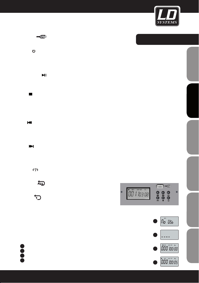
USB PORT
Für USB Speicher Stick
MP3 PLAYER:
POWER
Wenn das Modul aus ist, drücken Sie die Power-Taste für 2-3 Sekunden um den Player einzuschalten.
Wiederholen Sie diesen Vorgang, um den Player wieder auszuschalten.
Wenn der Player angeschaltet wird, befindet er sich automatisch in „Pause“.
PLAY / PAUSE
Drücken Sie während der Wiedergabe die Play/Pause -Taste um die Wiedergabe zu pausieren. Drücken SIe die
Play / Pause -Taste erneut, um die Wiedergabe fortzusetzen.
STOP
Drücken Sie während der Wiedergabe die Stop -Taste, um die Wiedergabe zu stoppen. Die Anzahl der auf dem
Memory Stick befindlichen Titel wird nun auf dem Display angezeigt.
Im Stop -Modus, drücken Sie den PRE/NEXT oder den Stop -Knopf erneut, um im Pause Modus zum 1. Titel zu
gelangen. Drucken Sie dann den Play/Pause Knopf, um die Wiedergabe zu starten.
PRE
Wenn Sie im Pause Modus diese Taste drücken, gelangen Sie zum vorrigem Titel. Pause bleibt aktiviert. Drücken
Sie die Play/Pause Taste, um die Wiedergabe zu starten. Wenn Sie diese Taste während der Wiedergabe drücken,
wird der vorrige Titel direkt abgespielt.
NEXT
Wenn Sie im Pause Modus diese Taste drücken, gelangen Sie zum nächsten Titel. Pause bleibt aktiviert. Drücken
Sie die Play/Pause Taste, um die Wiedergabe zu starten. Wenn Sie diese Taste während der Wiedergabe drücken,
wird der nächste Titel direkt abgespielt.
REPEAT
Drücken Sie diesen Knopf , um zwischen den folgenden 4 Modi zu wählen
1. REP ALL
Alle im Speicher befindlichen Titel wiederholen.
MUSIC PLAY ER
FRANCAIS
FRANCAIS
ENGLISH
DEUTSCH
FRANCAIS
FRANCAIS
FRANCAIS
ESPAÑOL
2. REP 1
Einen Song wiederholen.
3. PLAY IN ORDER
Die Titel entsprechend einer Auswahl abspielen. Bildschirm bleibt leer
4. RANDOM PLAY
Spielt die Titel per Zufall ab. Das Zeichen auf dem Bildschirm ist A
BEACHTEN SIE:
A
Wenn kein USB Stick eingesteckt ist, sehen Sie folgenden Bildschirm
B
Wenn der Spieler nach MP3 Titeln sucht, sehen Sie folgenden Bildschirm
C
Wenn der Spieler im Pause Modus ist, sehen Sie folgenden Bildschirm
D
Wenn der Spieler in Betrieb ist, sehen Sie folgenden Bildschirm
POLSKI
A
B
C
D
ITALIANO
41
Page 42
HERSTELLERERKLÄRUNGEN:
GARANTIEBESTIMMUNGEN
Diese Garantie erstreckt sich auf die Marken Adam Hall, LD Systems, Defender, Palmer und Eminence.
Die gesetzlichen Gewährleistungsrechte gegenüber dem Verkäufer werden von dieser Garantie nicht berührt. Viel-
ENGLISHDEUTSCHFRANCAIS
mehr begründet diese Garantie zusätzliche selbständige Ansprüche gegenüber Adam Hall.
Mit dieser Garantie stellt Adam Hall sicher, dass das von Ihnen bei Adam Hall oder einem Adam Hall Partner
erworbene Produkt bei normalem Gebrauch während des Zeitraums von 2 bzw. 5 Jahren ab Kaufdatum frei von
Material- oder Verarbeitungsfehlern ist.
Der Garantiezeitraum beginnt mit dem Datum des Kaufs.
Der Geltendmachung eines Anspruchs auf Garantieleistungen erforderliche Nachweis des Kaufdatums, erfolgt
durch die mit dem Kaufdatum versehene Quittung oder den mit dem Kaufdatum versehenen Lieferschein. Sie ha-
ben Anspruch auf den Garantieservice zu den in diesem Dokument aufgeführten Bedingungen und Bestimmungen,
falls eine Reparatur der unter den oben genanten Marken vertriebenen Produkte innerhalb des Garantiezeitraums
erforderlich ist.
Diese Garantie gilt nur für den ursprünglichen Käufer des von Adam Hall vertriebenen Produkts und ist nicht an
Personen übertragbar, denen vom ursprünglichen Käufer das Eigentum am Adam Hall Produkt übertragen wird.
Innerhalb des Garantiezeitraums werden die fehlerhaften Komponenten oder das Produkt von Adam Hall repariert
oder ersetzt. Alle im Rahmen dieser Garantie entfernten Komponenten und Hardware-Produkte gehen in das Eigentum von Adam Hall über.
In dem unwahrscheinlichen Fall, dass bei dem von Ihnen erworbenen Adam Hall Produkt ein Fehler wiederholt auftritt, kann Adam Hall nach eigenem Ermessen entscheiden, Ihnen dieses Produkt durch ein vergleichbares Produkt
mit mindestens derselben Leistung zu ersetzen.
ESPAÑOLPOLSKIITALIANO
Adam Hall übernimmt keine Garantie für einen störungs- oder fehlerfreien Betrieb dieses Produkts. Adam Hall
übernimmt keine Verantwortung für auf eine inkorrekte Befolgung der im Lieferumfang des Adam Hall erhaltenen
Anweisungen zurückzuführende Schäden.
FRANCAISFRANCAIS
FRANCAISFRANCAIS
42
26
Diese Garantie erstreckt sich nicht auf
- Verschleißteile (z.B. Akkumulator).
- Geräte deren Seriennummer entfernt wurde.
- Geräte, die durch Eigenverschulden beschädigt wurden.
- unsachgemäß oder mißbräuchlich verwendete Geräte.
- Geräte, die nicht entsprechend den Betriebsparametern betrieben wurden, welche im Lieferumfang des
Produkts enthaltenen Benutzerunterlagen festgelegt sind.
- Geräte, die aufgrund der Verwendung nicht von Adam Hall hergestellter oder vertriebener Teile repariert wurden.
- Geräte, die durch Änderung oder Wartung durch jemand anderen als Adam Hall getätigt wurden.
Diese Bestimmungen und Bedingungen stellen die vollständige und ausschließliche Garantievereinbarung zwischen Ihnen und Adam Hall für das von Ihnen erworbene Adam Hall Produkt dar.
Page 43

HERSTELLERERKLÄRUNGEN:
NOTES:
HAFTUNGSBESCHRÄNKUNG
Wenn das unter der Marke Adam Hall vertriebene Produkt nicht entsprechend der obigen Garantie funktioniert,
besteht Ihr alleiniger und ausschließlicher Anspruch aus dieser Garantie in der Reparatur oder dem Ersatz.
Weitergehende Gewährleistungsansprüche bleiben hiervon unberührt. Die maximale Haftung von Adam Hall im
Rahmen dieser Garantie ist ausdrückliche beschränkt auf den jeweils niedrigeren Betrag, der sich entweder aus
dem Kaufpreis für das Produkt oder aus den Reparatur- bzw. Ersatzkosten von Hardware-Komponenten, die bei
normalem Gebrauch nicht Ordnungsgemäß funktionieren, ergibt.
Adam Hall haftet aus dieser Garantie nicht für durch das Produkt oder sein versagen verursachte Schäden, einschließlich entgangener Gewinne, unterbliebener Einsparungen oder besonderer, indirekter oder Folgeschäden.
Adam Hall haftet zudem nicht für von Dritten oder von ihnen für Dritte geltend gemachte Ansprüche.
Diese Haftungsbeschränkung gilt unabhängig davon, ob Schäden gerichtlich verfolgt werden, ob Schadensersatzansprüche im Rahmen dieser Garantie oder aufgrund unerlaubter Handlungen (Einschließlich Fahrlässigkeit
und Gefährdungshaftung) oder aufgrund vertraglicher bzw. sonstiger Ansprüche gestellt werden. Diese Haftungsbeschränkung kann von keiner Person aufgehoben oder ergänzt werden. Diese Haftungsbeschränkung gilt auch
dann, wenn sie Adam Hall über die Möglichkeit derartiger Schäden informiert haben. Sie gilt jedoch nicht für
Ansprüche aus Personenschäden.
Aus dieser Garantie ergeben sich für Sie bestimmte Rechte. Möglicherweise haben Sie weitere Rechte, die Ihnen
von Staat zu Staat und von Land zu Land unterschiedlich sein können. Es ist ratsam, die entsprechenden Gesetze
des Staates bzw. Landes heranzuziehen, um Ihre Rechte umfassend zu ermitteln.
INANSPRUCHNAHME DES REPARATURSERVICE
Um den Garantieservice bzw. Reparaturservice für das Produkt in Anspruch zu nehmen, wenden Sie sich bitte an
Adam Hall oder an einen Adam Hall Partner, bei dem Sie das Produkt erworben haben.
FRANCAIS
FRANCAIS
ENGLISH
DEUTSCH
FRANCAIS
FRANCAIS
FRANCAIS
ESPAÑOL
EG-KONFORMITÄTSERKLÄRUNG
Diese Geräte entsprechen den grundlegenden Anforderungen und den weiteren Vorgaben der Richtlinien 1999/5/
EU, 89/336/EU und 73/23/EU.
KORREKTE ENTSORGUNG DIESES PRODUKTES
(Gültig in der Europäischen Union)
Dieses Symbol (entweder auf dem Gerät oder dem dazugehörigen Handbuch) weist darauf hin, dass das Gerät
nicht mit dem normalen Hausmüll entsorgt werden darf. Um mögliche Schäden an der Umwelt und an Personen zu
verhindern, entsorgen Sie dieses Gerät bitte fachgerecht bei einer entsprechenden Stelle für Elektromüll.
Als Privatkunde Informieren Sie sich bitte beim Hersteller oder bei Ihrer Gemeinde über die
Möglichkeiten der korrekten Entsorgung.
Als Geschäftskunde kontaktieren Sie bitte Ihren Lieferanten und prüfen Sie die Konditionen
zur Entsorgung der Geräte. Dieses Produkt sollte nicht mit anderem gewerblichen Abfall entsorgt werden.
POLSKI
ITALIANO
43
27
Page 44

HERSTELLERERKLÄRUNGEN:
WEEE-DEKLARATION
Ihr LD-Systems Produkt wurde unter der Verwendung hochwertiger Materialien und Komponenten die wiederverwertet oder wieder verwendet werden können hergestellt. Dieses Symbol weist darauf hin, dass elektronische
ENGLISHDEUTSCHFRANCAIS
Geräte nicht im normalen Hausmüll entsorgt werden dürfen. Entsorgen Sie dieses Gerät bitte fachgerecht bei
einer entsprechenden Stelle für Elektromüll und helfen Sie dabei unsere Umwelt zu schützen.
BATTERIEN UND AKKUS
Die mitgelieferten Batterien können wiederverwertet werden. Werfen Sie die Batterien daher nicht in den normalen Hausmüll sondern in gesonderte dafür vorgesehene Container. Helfen Sie, unsere Umwelt sauber zu halten.
ESPAÑOLPOLSKIITALIANO
FRANCAISFRANCAIS
FRANCAISFRANCAIS
Adam Hall GmbH, alle Rechte vorbehalten. Änderungen der Technischen Daten und Produktmerkmale vorbe-
halten. Das Erstellen von Fotokopien, Übersetzungen und anderen Reproduktionen dieser Bedienungsanleitung
oder Teilen derselben ohne vorherige Genehmigung ist untersagt.
44
28
Page 45

NOTES:
NOTIZEN:
FRANCAIS
FRANCAIS
ENGLISH
DEUTSCH
FRANCAIS
FRANCAIS
FRANCAIS
ESPAÑOL
POLSKI
ITALIANO
45
29
Page 46

ENGLISHDEUTSCHFRANCAIS
Merci d’avoir choisi LD-Systems!
Nous avons conçu ce produit afin de vous offrir un matériel fiable, qui vous accompagnera durant de longues
années. En achetant l’un des produits de la marque LD-Systems vous bénéficiez de notre compétence reconnue
et de nos nombreuses années d’expérience en tant que fabricant. Notre nom est notre garantie.
Veuillez s’il-vous-plait prendre quelques minutes pour lire attentivement ces instructions d’utilisation car nous
souhaitons que vous puissiez profiter pleinement et au plus vite de votre matériel LD-Systems.
Pour plus d’informations sur LD-Systems venez visiter notre site WWW.LD-SYSTEMS.COM
ESPAÑOLPOLSKIITALIANO
FRANCAISFRANCAIS
FRANCAISFRANCAIS
46
Page 47

LD LAX12D USB
FRANCAIS
FRANCAIS
ENGLISH
TABLE DE MIXAGE 12 ENTRÉES AVEC MULTIEFFET ET LECTEUR
MP3 SUR CLÉ USB
B
S
U
R
E
AY
L
P
C
I
S
U
M
E
L
O
S
N
O
C
G
IN
IX
M
Q
E
Q
E
Q
E
Q
E
Q
E
Q
E
Q
E
Q
E
R
L
R
L
R
L
R
L
R
L
R
L
R
L
R
L
DEUTSCH
FRANCAIS
FRANCAIS
FRANCAIS
ESPAÑOL
POLSKI
ITALIANO
47
Page 48

PRÉCAUTIONS D’UTILISATION:
1. Veuillez lire attentivement les précautions d’utilisation et les instructions suivantes.
2. Veuillez conserver ce manuel d’utilisation.
3. Veuillez utiliser cet appareil uniquement conformément à son but d’utilisation initial.
4. Veuillez respecter les règles de traitement des déchets. Veuillez s’il-vous-plait séparer les déchets plastiques
des déchets papiers et les déposer dans un bac à ordures adéquat.
ENGLISHDEUTSCHFRANCAIS
5. En cas de panne, de dommage, d’exposition de l’appareil à la pluie ou autres liquides, veuillez contacter une
personne qualifiée pour le service après-vente de nos produits.
6. Veuillez ne pas exposer ce produit à des sources de chaleur, telles que les fours, les radiateurs ou tout autre
appareil produisant de la chaleur (notamment les amplificateurs de puissance). Pour éviter les risques de
surchauffe veillez à ce que l’appareil ne soit pas placé trop près d’un mur, ou enfermé dans un boitier, pour
que la circulation de l’air ne soit pas obstruée.
7. Après avoir connecté votre appareil veuillez inspecter le câblage pour éviter les risques d’accident ou
d’avarie. Veuillez ne jamais utiliser de câbles endommagés.
8. Veuillez utiliser uniquement les accessoires et supports de fixation fournis ou recommandés par le
constructeur. Assurez vous de la stabilité de votre installation avant d’utiliser votre matériel, vous éviterez les
risques de chutes et donc de dommages de l’appareil.
9. Apparition d’interférences lors de l’usage de systèmes HF sans fil.
L’utilisation simultanée de micros sans fil et de téléphones portables (si les deux appareils sont peu éloignés
l’un de l’autre) peut générer des interférences au niveau du microphone. Ces interférences sont audibles dans
les haut-parleurs de votre système de sonorisation lorsque le système sans fil y est relié.
CAUTION
RISK OF ELECTRIC SHOCK
DANGER:
Pour réduire les risques de choc électrique veuillez ne pas retirer le couvercle (ou la face arrière) de l’appareil.
Les pièces situées à l’intérieur de l’appareil ne doivent pas être manipulées par l’utilisateur. Veuillez contacter
exclusivement une personne qualifiée pour le service après-vente de nos produits.
L’éclair finissant par une flèche, entouré d’un triangle équilatéral vous indique la présence à
l’intérieur du boîtier de pièces non isolées, représentant un risque de “haute tension électrique” et
pouvant par conséquent blesser les personnes.
ESPAÑOLPOLSKIITALIANO
DO NOT OPEN
Le point d’exclamation, entouré d’un triangle équilatéral, vous indique la présence d’instructions
importantes quant-à l’utilisation et à l’entretien dans la brochure fournie avec le produit.
ATTENTION! NIVEAU SONORE ÉLEVÉ!
Vous allez utiliser ce système de transmission sans fil à des fins professionnelles. Dans ce cas l’utilisation de ce
FRANCAISFRANCAIS
FRANCAISFRANCAIS
produit est soumise à des règles et à des directives définies par votre organisme professionnel de prévention
des accidents du travail. En tant que fabricant, Adam Hall se doit de vous mettre en garde formellement sur les
risques éventuels que cet appareil peut présenter pour votre santé.
Ce système est capable de générer une pression acoustique supérieure à 80dB. 85dB est la limite légale du
niveau sonore à laquelle votre ouïe peut être soumise lors d’une journée de travail. Cette valeur a été fixée
par la médecine du travail comme valeur de référence pour la mesure du niveau sonore. Vous exposer à des
niveaux sonores plus élevés, ou sur une durée plus longue peut endommager votre ouïe. Si vous vous exposez
à des pressions acoustiques supérieures à la limite légale, pensez à raccourcir le temps d’exposition pour vous
protéger d’éventuelles dégradations de votre ouïe. Voici quelques signes pouvant vous alerter d’une exposition
trop longue à un niveau sonore trop élevé :
- Vous entendez des sons de cloche, de sonnerie ou des sifflements !
- Vous avez l’impression de ne plus entendre les sons aigus !
48
Page 49

FONCTIONNALITÉS & PRISE EN MAIN:
INTRODUCTION
Merci d'avoir acheté un produit audio de la marque LD Systems. La LAX12D est une table de mixage compacte,
destinée à des applications professionnelles. Elle possède un son agréable et naturel et assure une restituti-
on précise – idéal pour les applications live, les enregistrements et les installations xes. La table de mixage
LAX12D offre quelques fonctions inhabituelles dans cette classe de prix. Les voies mono sont équipées de
préamplis micro de très faible bruit de fond, avec alimentation fantôme 48Volts. De plus, toutes les voies de
la table de mixage sont équipées d'un égaliseur alliant chaleur sonore et naturel: les voies mono possèdent
ainsi des égaliseurs 3 bandes (MID : fréquence médium réglable), les voies stéréo possèdent des égaliseurs 4
bandes à fréquence fixe. La LAX12D offre de plus des indicateurs de niveau de sortie de haute précision (sur
12 segments), une entrée pour magnétophone stéréo (2TK IN) assignable aux généraux et à la sortie casque/
écoute cabine, etc. Enfin, elle met à votre disposition un processeur d'effets 24bits, offrant 100 presets. La table
de mixage LAX12D est très facile à utiliser. Nous vous conseillons toutefois de lire ce manuel utilisateur dans sa
totalité avant première utilisation, afin de tirer les performances optimales de votre table de mixage.
POINTS FORTS
La table de mixage LAX12D a été développée pour des applications professionnelles. Elle offre les caractéristiques et fonctionnalités suivantes:
• Voies micro avec connecteur XLR plaqué or, faisant également ofce d'entrées ligne symétriques (sur jack TRS)
• Voies stéréo dotées de connecteurs jack TRS symétriques
• Préamplis micro à composants discrets, faible bruit de fond, alimentation fantôme 48Volts
• Niveau maximal de sortie élevé et réserve dynamique importante
• Voies mono avec points d'insertion
• Filtre passe-haut commutable sur toutes les voies mono
• Sélecteur de niveau de travail +4dBu/-10dBV sur toutes les voies stéréo
• Égaliseur 4 bandes (fréquences médium xes) sur les voies stéréo, alliant chaleur sonore et naturel
• Égaliseur 3 bandes (médium réglable, de 100 Hz à 8 kHz) sur les voies mono
• Indicateurs d'écrêtage (LED Peak) sur toutes les voies
• Fonctions Mute/Alt 3-4/Solo sur toutes les voies
• 2 retours AUX, utilisables comme entrées stéréo complémentaires
• Sortie écoute cabine (CTRL ROOM) et sortie casque (PHONES) dédiées
• Entrée stéréo (2-Track) assignable aux généraux, à la sortie cabine et à la sortie casque
• Indicateurs de niveau de sortie généraux de haute précision (visualisation sur 12 segments)
• Processeur d'effets numérique 24bits intégré
• 100 presets d'effets
• Fonction de Bypass d'effets, par touche MUTE ou pédale Footswitch (disponible en option, reliée au connecteur
DFX FOOTSWITCH)
FRANCAIS
FRANCAIS
ENGLISH
DEUTSCH
FRANCAIS
FRANCAIS
FRANCAIS
ESPAÑOL
POLSKI
ITALIANO
49
Page 50

FONCTIONNALITÉS & PRISE EN MAIN:
• Avant de connecter votre table de mixage LAX12D au secteur, vériez que la valeur de tension est conforme à
celle pour laquelle l'appareil est prévu.
• Assurez-vous que la table de mixage est éteinte avant de la brancher sur le secteur, et réglez tous ses potentiomètres sur 0. Vous évitez ainsi d'envoyer, lors de la mise sous tension, des bruits parasites de niveau élevé
ENGLISHDEUTSCHFRANCAIS
dans vos enceintes.
• Commencez toujours par allumer la console, puis le système d'écoute. Pour éteindre, procédez dans l'ordre
inverse : éteignez d'abord le système d'écoute, puis la table de mixage.
• Éteignez la LAX12D avant de brancher les câbles audio.
• Pour nettoyer la LAX12D, n'utilisez aucun produit liquide : un chiffon sec et doux suft. Pour éteindre, procédez
dans l'ordre inverse : éteignez d'abord le système d'écoute, puis la table de mixage.
• Éteignez la LAX12D avant de brancher les câbles audio.
• Pour nettoyer la LAX12D, n'utilisez aucun produit liquide : un chiffon sec et doux suft.
ESPAÑOLPOLSKIITALIANO
FRANCAISFRANCAIS
FRANCAISFRANCAIS
50
Page 51

ÉLÉMENTS DE CONTRÔLE :
1
VOIES MONO (MICRO/LIGNE)
Les voies mono sont équipées d'un connecteur XLR (symétrique, faible
impédance d'entrée) pour micro et toute source de signal de faible niveau.
Chaque voie mono dispose en plus d'un connecteur Jack 6,35mm, pour
appareils au niveau ligne (synthétiseur, boîte à rythmes, processeur d'effets,
etc.). Attention: Il n'est pas possible d'utiliser simultanément les connecteurs
d'entrée XLR (MIC) et Jack (LINE) d'une même voie. ALIMENTATION FANTÔME
Les entrées XLR des voies mono possèdent une alimentation fantôme 48 Volts,
indispensable au fonctionnement des micros statiques. Attention: Ne branchez
jamais de micros ne demandant pas de tension fantôme sur une entrée où la
tension 48 Volts est activée !
FRANCAIS
FRANCAIS
MIC 1
1
BAL OR
UNBAL
LINE IN 1
ENGLISH
DEUTSCH
FRANCAIS
FRANCAIS
2
RÉGLAGE DU GAIN D'ENTRÉE
Le potentiomètre de réglage de gain d'entrée possède deux modes de
fonctionnement : l'un s'applique à l'entrée micro, l'autre à l'entrée ligne. La
graduation extérieure (MIC, 0 à 40 dB) s'applique au signal de l'entrée micro
sur XLR, la graduation intérieure (LINE, +15 à -25 dB) au signal de l'entrée
ligne sur jack. Réglez le potentiomètre de gain de façon à ce que la LED Peak
située au-dessus du fader de la voie ne clignote qu'occasionnellement. Si la
LED reste allumée, de la distorsion peut apparaître.
3
FILTRE PASSE-HAUT (LOW CUT)
La touche LOW CUT active un filtre passe-haut, atténuant les fréquences
inférieures à 75 Hz selon une pente de 18 dB/octave. Ce ltre sert à réduire
les parasites dans les graves, provoqués par les bruits d'air ou les bruits de
manipulation des micros de chant.
4
VOIES STÉRÉO
Les voies stéréo sont équipées de deux connecteurs jack 6,35 mm TRS. Ces
entrées sont compatibles avec un signal mono (à connecter sur le Jack du
canal gauche).
5
SÉLECTEUR +4dBu/-10dBV
Les entrées stéréo au niveau ligne possèdent une sensibilité commutable : la po-
sition +4 dBu correspond aux appareils audio professionnels, la position -10 dBV
aux appareils hi-fi et autres. Si vous ne savez pas quelle position est la mieux
adaptée à l'appareil que vous connectez, essayez d'abord la position +4 dBu. Si
le niveau ainsi obtenu n'est pas sufsant, passez à la position -10 dBV.
6
DÉPARTS AUXILIAIRES (AUX SENDS)
Ces connecteurs jack 6,35 mm permettent de récupérer le signal des bus auxiliaires 1 et 2, prélevés sur chaque voie, à destination d'un multieffet externe par
exemple. Vous pouvez aussi utiliser ces sorties pour effectuer des prémixages.
2
LINE
+15dB -25dB
MIC
0dB 40dB
FRANCAIS
3
LOW CUT
75Hz 18dB/Oct
LINE IN 19/20
ESPAÑOL
4
5
6
LEFT(MONO)
RIGHT
-10dBV
AUX SENDS
1
2
+4dBu
POLSKI
ITALIANO
7
PHONE
51
Page 52

ÉLÉMENTS DE CONTRÔLE:
7
PHONE
Ce jack stéréo permet d'écouter au casque le signal de sortie des
ENGLISHDEUTSCHFRANCAIS
généraux (MAIN MIX).
ÉGALISEUR
Les voies mono de la table de mixage LAX12D sont équipées d'un
égaliseur 3 bandes (HI/MID/LOW, bande MID de fréquence réglable),
les voies stéréo possèdent des égaliseurs 4 bandes (HI, HI-MID,
MID-LOW et LOW), fréquences fixes pour les deux bandes MID. Le
gain est réglable entre +15 dB et -15 dB sur chaque bande.
8
HI
Ce potentiomètre permet d'agir sur les aigus, afin de donner plus
de brillance et de présence au son, ou d'atténuer des fréquences
élevées mises trop en avant. La fréquence centrale d'intervention
est de 12 kHz, le gain réglable entre +15 dB et -15 dB.
9
MID
Ce potentiomètre permet d'agir sur les médiums, fréquences très
importantes pour les instruments de musique et la voix. Le gain est
réglable entre -15 et +15 dB. Le potentiomètre FREQ permet de régler précisément la fréquence d'intervention, entre 100 Hz et 8 kHz.
8
10
9
11
12
13
10
ESPAÑOLPOLSKIITALIANO
11
FRANCAISFRANCAIS
FRANCAISFRANCAIS
12
52
HI-MID
Ce potentiomètre permet d'agir sur le haut-médium (fréquence
fixe, située à peu près à mi-course du potentiomètre FREQ de la
bande MID). Ces possibilités de réglage offrent une souplesse
encore accrue, et permettent de travailler en détail le registre
médium, très important.
MID-LOW
Ce potentiomètre permet d'agir sur le bas-médium (fréquence
centrale d'intervention 500 Hz, gain réglable de -15 dB à +15 dB).
LOW
Ce potentiomètre permet d'agir sur les fréquences graves– grosse caisse, guitare basse, voix d'homme...– pour conférer plus
d'assise au son (fréquence centrale d'intervention 80 Hz, gain
réglable de -15 dB à +15 dB).
14
15
16
17
KAEPKAEP
10
dB
5
0
-5
-10
18
-15
-20
-30
-40
-60
OO
10
dB
5
0
-5
-10
-15
-20
-30
-40
-60
O
O
Page 53

ÉLÉMENTS DE CONTRÔLE:
13
DÉPART AUXILIAIRE (AUX SEND)
Ces deux potentiomètres permettent de régler le niveau de signal de la voie prélevé sur les bus AUXiliaires
1 et 2. Le signal des généraux stéréo (MAIN MIX) n'est pas affecté. Le départ AUX 1 peut être prélevé avant
ou après fader, grâce à la touche PRE/POST. En position POST (touche non enfoncée), le signal de la voie est
prélevé après son passage par le fader. Toute modification de position du fader se traduit donc par un changement de niveau du signal du départ auxiliaire. En position PRE (touche enfoncée), le signal de la voie est
prélevé avant son passage par le fader. Même si la position du fader change, le niveau de départ auxiliaire
reste constant. Le départ AUX 2 est exclusivement de type POST (après fader).
14
PAN/BAL
Les voies mono de la LAX12D possèdent un potentiomètre de panoramique (PAN); les voies stéréo disposent
d'un potentiomètre de balance (BAL). Dans les deux cas, ils servent à modier la répartition du signal de la
voie sur les canaux gauche et droit des généraux.
15
MUTE/ALT3-4
Toutes les voies de la LAX12D sont munies d'une touche MUTE/ALT3-4, permettant d'envoyer le signal de la
voie correspondante sur la sortie ALT3-4.
16
SOLO
La touche SOLO sert à n'écouter que le signal de la voie sur laquelle la fonction Solo est activée (touche
enfoncée), les signaux des autres voies étant alors coupés automatiquement. La touche SOLO est utile pour
régler le gain d'entrée de la voie, ainsi que pour écouter rapidement en isolation un signal, afin de déceler un
éventuel problème.
17
LED PEAK
Toutes les voies de la LAX12D sont munies d'une LED PEAK, permettant de repérer un niveau d'entrée
excessif. Lorsque l'indicateur PEAK s'allume (6 dB en dessous du niveau où apparaît la distorsion), c'est que
le signal de la voie est proche de sa valeur maximale autorisée, et que de la distorsion peut apparaître.
FRANCAIS
FRANCAIS
ENGLISH
DEUTSCH
FRANCAIS
FRANCAIS
FRANCAIS
ESPAÑOL
POLSKI
ITALIANO
53
Page 54

ÉLÉMENTS DE CONTRÔLE:
18
FADER DE VOIE
ENGLISHDEUTSCHFRANCAIS
Les faders servent à régler le volume sonore du signal présent sur chaque voie, autrement dit le niveau
envoyé sur les sorties des généraux (MAIN MIX).
19
2-TRACK IN/OUT
TAPE IN : L'entrée TAPE IN permet de brancher un enregistreur stéréo externe. Appuyer sur la touche 2TK IN
sur le panneau de la console envoie le signal arrivant sur l'entrée TAPE IN sur la sortie PHONES/CONTROL
ROOM ; appuyer sur la touche 2TK TO MAIN MIX envoie le signal 2TK sur les généraux (MAIN MIX). TAPE
OUT : Ces deux connecteurs RCA (Cinch) permettent d'envoyer le signal des généraux de la console vers
un enregistreur externe. POTENTIOMÈTRE 2TK IN : Ce potentiomètre permet de régler le niveau d'entrée du
signal 2TK IN, entre - ∞ et MAX.
20
ESPAÑOLPOLSKIITALIANO
FRANCAISFRANCAIS
FRANCAISFRANCAIS
STEREO AUX RETURNS
Ces jacks TRS 6,35 mm sont prévus, à l'origine, pour intégrer au mixage stéréo (MAIN MIX) le signal audio
provenant d'un multieffet externe. Ils peuvent aussi servir d'entrées AUX supplémentaires. Rappel: Tant
qu'aucun connecteur n'est inséré dans les entrées AUX RETURN 2, le retour auxiliaire 2 gère le signal issu du
processeur d'effets intégré à la console.
1
LEFT(MONO)
RIGHT
2
STEREO AUX RETURNS
20
RIGHT
2TK IN
LEFT
TAPE IN TAPE OUT
2-TRACK IN/OUT
L
R
19
MAX
54
Page 55

21
POTENTIOMÈTRE AUX RETURN
Ces potentiomètres permettent de régler les niveaux
des retours auxiliaires 1 et 2 ; les signaux correspondants sont sommés à celui des généraux stéréo
(MAIN MIX) de la table de mixage.
22
EFX TO AUX 1
Cette touche permet d'intégrer le signal de retour
auxiliaire (AUX RETURN) 2 au signal envoyé sur la
sortie AUX 1. Très pratique pour envoyer les effets
dans la balance casques (mix Monitor)...
23
DÉPART AUXILIAIRE (AUX SEND)
Ces potentiomètres servent à régler le niveau Master
du départ auxiliaire 1 et 2 (de -∞ à +15 dB). Vous
pouvez ainsi, si besoin est, amplifier d'un maximum
de 15 dB le niveau de sortie des départs auxiliaires.
24
INDICATEUR DE NIVEAU DE SORTIE
Cette échelle de 2 x 12 LED permet de visualiser le
niveau de sortie stéréo de la table de mixage.
25
TOUCHE SOLO MODE ET LED SOLO ACTIVE
Cette touche permet de choisir entre les deux modes
de Solo disponibles sur la table de mixage : PFL
(écoute avant fader, touche non enfoncée) ou AFL
(écoute après fader, touche enfoncée).
En mode PFL, le signal écouté en SOLO est prélevé
avant le fader de la voie. Autrement dit, son niveau
d'écoute ne dépend pas de la position du fader. En
mode AFL, le signal écouté en SOLO est prélevé après
son passage par le fader et le panoramique de la voie
(qui, bien qu'il se trouve physiquement au-dessus
du fader, est implanté techniquement après lui).
Autrement dit, le mode AFL permet d'écouter le signal
de la voie avec le niveau et le panoramique qui lui
sont appliqués dans le mixage. Rappel: Le mode
SOLO (PFL/AFL) s'active dès que vous appuyez sur la
touche de Solo d'une voie. Dans ce cas, la LED SOLO
ACTIVE s'allume.
ÉLÉMENTS DE CONTRÔLE :
0
1
8
-
+15
AUX RTN 1
21
8
-
AUX RTN 2
0
22
EFX TO AUX 1
0
1
8
-
23
0
2
8
-
AUX SENDS
24
SOLO
ACTIVE
25
SOLO MODE
26
+15
+15
DFX
+15
LEVEL
2
SET
10
dB
-5
-10
-15
-20
-30
-40
-60
ALT 3-4
PFL
AFL
5
0
8 8
00-09 Echo
10-19 Echo +Verb
20-29 Tremolo
30-39 Plate
40-49 Chorus
PEAK/MUTE
-
PHONES
CONTROL ROOM
LR
OUTPUT LEVEL
8
CLIP
+10
0
+7
+4
+2
0
-2
-4
-7
-10
-20
-30
FUNCTION
+15
PWRPHANTOM
PROGRAM (PUSH)
50-59 Vocal
60-69 Rotary
70-79 Small Room
80-89 Flange+Verb
90-99 Large Hall
MAIN MIX
LEVEL
10
dB
5
0
-5
-10
-15
-20
-30
-40
-60
LEFT
DFX MUTE
CTR ROOM
SOURCE
MAIN MIX
ALT 3-4
2TK IN
ASSIGN
TO MIX
ALT 3-4
2TK
RIGHT
10
dB
5
0
-5
-10
-15
-20
-30
-40
-60
33
32
31
30
29
28
27
FRANCAIS
FRANCAIS
ENGLISH
DEUTSCH
FRANCAIS
FRANCAIS
FRANCAIS
ESPAÑOL
POLSKI
ITALIANO
55
Page 56

ÉLÉMENTS DE CONTRÔLE:
26
FADER ALT3-4
Ce fader permet de régler le niveau de la sortie ALT (gain : de -∞ à +10 dB).
27
ENGLISHDEUTSCHFRANCAIS
ESPAÑOLPOLSKIITALIANO
FADERS MAIN MIX LEVEL
Ces deux faders (LEFT et RIGHT) permettent de régler le niveau du signal stéréo envoyé aux sorties des
généraux (MAIN MIX) et à la sortie enregistrement (TAPE OUT).
28
TK TO MAIN MIX
Appuyer sur cette touche envoie le signal arrivant sur l'entrée 2-TRACK aux généraux stéréo (MAIN MIX).
29
ALT3-4 TO MAIN MIX
Appuyer sur cette touche envoie le signal ALT3-4 sur les généraux (MAIN MIX), où il est sommé au signal
déjà existant.
30
CONTROL ROOM SOURCE
Ces touches permettent de choisir le signal que vous désirez envoyer sur vos enceintes ou écouter au
casque : MAIN MIX, ALT 3-4, 2TK IN. Attention : ces touches ne sont pas actives si le mode Solo est activé !
Si, après avoir appuyé sur une des touches CONTROL ROOM SOURCE, vous n'entendez pas le signal choisi,
vérifiez que le mode Solo n'est pas activé (aucune touche de Solo enfoncée sur une voie).
31
LED PWR (POWER)
Cette LED s'allume pour indiquer que la table de mixage est sous tension.
32
LED PHANTOM
Cette LED s'allume pour indiquer que la tension d'alimentation fantôme est activée.
33
POTENTIOMÈTRE PHONE/CONTROL ROOM
Ce potentiomètre vous permet de régler le niveau du signal envoyé à la régie (CONTROL ROOM) et à la sortie
casque (PHONE).
FRANCAISFRANCAIS
FRANCAISFRANCAIS
56
Page 57

PROCESSEUR D'EFFETS NUMÉRIQUE 24 BITS
34
TOUCHE DFX MUTE
Cette touche permet d'activer/désactiver le multieffet intégré à la console de mixage. Pour plus de commodité, vous
pouvez également contrôler cette fonction au pied, via une
pédale de type Footswitch connectée au jack FOOT SW.
35
AFFICHEUR LED
Cet afficheur à deux chiffres indique le numéro du Preset
sélectionné.
36
MOLETTE DE SÉLECTION DE PRESET
Cette molette permet de sélectionner le Preset d'effet
désiré. La LAX12D met 100 Presets d'effets à votre disposition : échos, réverbérations de type Vocal ou Plate, et
plusieurs combinaisons de deux effets. Une fois que vous
avez sélectionné le numéro de Preset désiré, appuyez sur
la molette de sélection pour valider ce choix.
37
LED PEAK
Cette LED s'allume dès que le niveau du signal d'entrée
du multieffet est trop élevé, ce qui risque de se traduire
par de la distorsion. Lorsque le multieffet numérique est
désactivé, cette LED reste allumée.
ÉLÉMENTS DE CONTRÔLE:
PROGRAM (PUSH)
35
88
37
FUNCTION
00-09 Echo
10-19 Echo +Verb
20-29 Tremolo
30-39 Plate
40-49 Chorus
PEAK/MUTE
50-59 Vocal
60-69 Rotary
70-79 Small Room
80-89 Flange+Verb
90-99 Large Hall
DFX MUTE
FRANCAIS
FRANCAIS
ENGLISH
36
DEUTSCH
FRANCAIS
FRANCAIS
34
FRANCAIS
ESPAÑOL
POLSKI
ITALIANO
57
Page 58

PANNEAUARRIÈRE:
44 42
Apparaten skall anslutas
PHAN TOM
till jordat uttag nar den
ansluts till ett natverk
ENGLISHDEUTSCHFRANCAIS
ON OFF
AC INPUT
£
210-240V 50Hz
RATED POWER CONSUMPTION: 23W
POWER
43 45 41 40 39 38
38
POINTS D'INSERTION (VOIES MONO)
Toutes les voies mono (micro/ligne) de la table de mixage sont pourvues d'un point d'insertion sur jack TRS,
ce qui permet d'insérer un processeur externe dans le chemin du signal audio. Le signal audio est prélevé
sur la voie juste après passage par le potentiomètre de gain (TRIM), ce qui est idéal pour le traiter par un
compresseur ou un limiteur, par exemple. Après passage par le processeur externe, le signal audio revient
dans la voie avant l'égaliseur. Rappel: Pour connecter un processeur externe via un point d'insertion, il faut
utiliser un cordon spécique, dit "en Y".
39
SORTIE CTRL ROOM
Ces jacks 6,35 mm permettent d'envoyer le signal de sortie de la console vers le système d'écoute du studio
ou vers un système de sonorisation.
40
SORTIE ALT
Ces jacks 6,35 mm asymétriques correspondent à une sortie complémentaire, dont le niveau se règle par
l'intermédiaire du fader ALT 3-4 situé dans la section Master de la table de mixage (niveau de sortie maxi :
ESPAÑOLPOLSKIITALIANO
+22 dBu). Les signaux des voies sur lesquelles la touche Mute/Alt 3-4 est enfoncée sont envoyés sur ce bus
complémentaire : ils n'apparaissent plus sur la sortie principale (MAIN MIX).
EUROPE
Fuse:T250mAL
FOOT SW
RIGHT
MAIN MIX OUTPUT(BAL/UNBAL)
RIGHT
LEFT
LEFT
WARNING: SHOCK HAZARD
AVIS: RISQUE DE CHOC ELECTRIQUE
CAUTION
RISK OF ELECTRIC SHOCK
OUTPUT
DO NOT OPEN
L
R
CAUTION:
REPLACE WITH THE SAME TYPE FUSE AND RATING
- DO NOT OPEN
DISCONNECT SUPPLY CORD BEFORE CHANGING FUSE
- NE PAS OUVRIR
LEFT(3)
INSERT
RIGHT(4)
ALT OUTPUTCTRL ROOM
INSERT
MODEL
SERIAL
3 4
2
INSERT
INSERT
1
41
FRANCAISFRANCAIS
FRANCAISFRANCAIS
42
43
58
SORTIE MAIN MIX
Les généraux stéréo de la console (MAIN MIX) possèdent deux paires de connecteurs : XLR et jack 6,35 mm.
Il s'agit de la sortie principale de la console, à envoyer vers les amplificateurs de puissance par exemple. Le
réglage du niveau de sortie s'effectue par l'intermédiaire des faders MAIN MIX (gain de -∞ à +10 dB).
JACK FOOT SW
Ce jack sert à connecter une pédale de type Footswitch (sélecteur au pied). Vous pouvez dès lors activer/
désactiver à distance le processeur d'effet intégré, comme si vous appuyiez sur la touche DFX MUTE.
INTERRUPTEUR PHANTOM
Cet interrupteur permet d'activer la tension d'alimentation fantôme +48 Volts, appliquée aux 4 connecteurs
d'entrée micro XLR. Attention: Assurez-vous que la tension d'alimentation fantôme est désactivée avant de
connecter des microphones aux entrées XLR.
Page 59

INSTALLATION ET CÂBLAGE:
44
INTERRUPTEUR POWER
Cet interrupteur permet d'allumer (ON) ou d'éteindre (OFF) la console.
45
EMBASE SECTEUR (AC INPUT)
Cette embase permet de relier le cordon secteur.
INSTALLATION ET CÂBLAGE :
Si vous vous êtes familiarisé au préalable avec les différentes fonctions que propose la table de mixage LAX12D,
son utilisation ne devrait pas vous poser de problème particulier. C'est pourquoi nous vous recommandons de
lire attentivement les pages qui suivent : vous y trouverez nombre d'astuces qui vous aideront à tirer le meilleur
de votre table de mixage.
- Assurez-vous, avant de brancher micros et instruments, que le fader de la voie et ceux des généraux (MAIN
MIX) de la table de mixage LAX12D sont baissés.
- Vériez que tous les appareils externes constituant votre conguration audio– microphones, amplicateurs de
puissance, enceintes, processeurs d'effets, etc.– sont correctement branchés.
- Lorsque vous décidez des passages de câbles, vérifiez que personne ne puisse être blessé, ni les appareils
endommagés.
- Réglez le niveau de sortie de la table de mixage et celui du système d'écoute connecté de façon à ne pas
dépasser 75% des valeurs nominales.
- Réglez le niveau du potentiomètre PHONE/CONTROL ROOM de façon à ne pas dépasser 50%.
- Réglez les différentes bandes d'égalisation (HI, MID, LOW) en position neutre (médiane)
- Réglez les potentiomètres de panoramique/balance (PAN/BAL) en position médiane.
- Réglez le gain de la voie en plaçant le fader au gain nominal (0 dB), et réglez le potentiomètre rotatif de gain
alors que quelqu'un parle dans le micro ou joue de l'instrument : la LED PEAK de la voie correspondante ne
soit s'allumer que de façon intermittente. Vous disposerez ainsi d'une réserve dynamique suffisante, sans pour
autant remonter le bruit de fond.
- Affinez ensuite le son de la source en réglant à votre goût l'égaliseur de la voie correspondante.
- Répétez ces étapes pour toutes les voies d'entrée recevant un signal audio, et surveillez les indicateurs de
niveau des généraux (double échelle de 12 LED repérée OUTPUT LEVEL) : ils ne doivent pas se retrouver trop
souvent dans le rouge.
FRANCAIS
FRANCAIS
ENGLISH
DEUTSCH
FRANCAIS
FRANCAIS
FRANCAIS
ESPAÑOL
POLSKI
CONNECTEURS AUDIO
La table de mixage LAX12D permet de connecter des sources de signal symétriques ou asymétriques, sur
connecteurs XLR et/ou jack 6,35mm (TRS). Nous y reviendrons plus en détail par la suite.
CÂBLAGE
Grâce à ses connecteurs XLR et jack 6,35mm (TRS), la LAX12D permet de travailler avec des sources de signal
possédant des sorties symétriques ou asymétriques. Voici quelques précisions sur le câblage de votre système:
ITALIANO
59
Page 60

CÂBLAGE:
POUR JACK
ENGLISHDEUTSCHFRANCAIS
6,35 MM
POUR CONNECTEUR
XLR :
ASYMÉTRIQUE
Tip
Sleeve
Pin1 ( )
+
ASYMÉTRIQUE
SYMÉTRIQUE
Ring
Pin2 (+)
Pin3 (-)
(Linked to Pin1 manually, )
+
-
Tip
Sleeve
Pin3 (-)
ASYMÉTRIQUE
Ring
SYMÉTRIQUE
Pin1 ( )
CÂBLAGE DIRECT
La table de mixage met à votre disposition des entrées sur jack 6,35 mm et sur XLR, ce qui permet de connecter
toutes sortes d'appareils audio, professionnels ou semi-pro. Vous trouverez ci après des exemples d'utilisation
pour chacun des connecteurs.
Tip
Sleeve
Sleeve
Ring
1
2
3
Tip
Ring
ESPAÑOLPOLSKIITALIANO
TIPRINGSLEEVE
1
3
2
SYMÉTRIQUE
TIPRINGSLEEVE
SLEEVERING TIP
1
3
2
1 2
3
Pin2 (+)
+
Tip
Sleeve
Tip
Ring
Sleeve
1
2
3
1
2
3
FRANCAISFRANCAIS
FRANCAISFRANCAIS
60
TIPRINGSLEEVE
TIPSLEEVE
3
2 1
TIPSLEEVE
TIPRINGSLEEVE
ASYMÉTRIQUE
TIPSLEEVE
TIPRINGSLEEVE
3
2 1
SLEEVETIP
SLEEVERINGTIP
Sleeve
Sleeve
Sleeve
Sleeve
Sleeve
Sleeve
Tip
Ring
Tip
1
2
3
Tip
Tip
Ring
Tip
Tip
Ring
1
2
3
1
3
2
1 2
3
1
3
2
1
2
3
1
2
3
Cent er
Screen
Tip
Sleeve
Tip
Ring
Sleeve
Cent er
Screen
Centre
Screen
1
2
3
Page 61
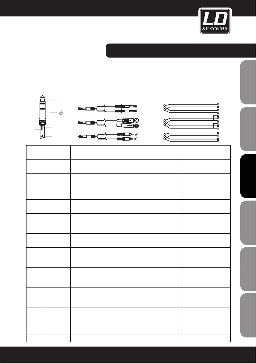
CÂBLE DU CÂBLE D'INSERTION
CÂBLAGE/LISTE DES PRESETS:
Pour relier un processeur de signal externe à un des points d'insertion de la LAX12D, il faut utiliser un câble en
Y : un jack TRS d'un côté, deux jacks TS de l'autre (envoi/retour du signal). Voici les modalités de câblage de ce
câble dit "en Y" :
POUR CÂBLE D'INSERTION JACK 6,35
MM STÉRÉO (TRS)
Ring
NUMÉ-RONOM DU
PRESET
Send
Return
Tip
Sleeve
TIP RING SLEEVE
TIP RING SLEEVE
TIP RING SLEEVE
SLEEVE TIP
SLEEVE RING TIP
12
3
2
3
1
DESCRIPTION PARAMÈTRES DISPO-
Sleeve
Sleeve
Sleeve
Tip
Ring
Tip
Ring
Tip
Ring
NIBLES
00-09 Echo Répétitions régulières du signal d'entrée, à intervalle réglable Durée de délai (Delay Time) :
145 à 205 ms
10-19 Echo+Verb Écho et réverbération Durée de délai (Delay Time) :
208 à 650 ms (écho), durée
de réverbération (Decay
Time) : 1,7 à 2,1 s
20-29 Tremolo Modulation cyclique de l'amplitude du signal Fréquence (Rate) : 0,6
Hz - 5 Hz
30-39 Plate Réverbération : Simulation d'une réverbération à plaque, idéale sur
les voix.
Durée de réverbération
(Decay Time) : 0,9 à 3,6 s
(donne de la brillance)
40-49 Effet Chorus Donne l'impression de la présence de plusieurs signaux à partir d'un
seul (voix, par exemple).
50-59 Vocal Réverbération : Simulation d'une petite pièce, de durée de réverbé-
ration courte
Fréquence (Rate) : 0,92 Hz
à 1,72 Hz
Durée de réverbération
(Decay Time) : 0,8 à 0,9 s
Pré-délai : 0 à 45 ms
60-69 Rotary Simulation de l'effet de haut-parleur tournant (cabine Leslie), avec
enceinte grave
Intensité de la modulation
(Mod Depth) :
20% ~ 80%
70-79 Small room Réverbération : Simulation de la réverbération d'un petit local, type
studio, avec un son brillant
Durée de réverbération
(Decay Time) : 0,7 à 2,1 s
Pré-délai : 20 à 45 ms
80-89 Flanger + Verb Combinaison d'un effet de Flanger (délai modulé en durée) et de
réverbération
Durée de réverbération
(Decay Time) : 1,5 à 2,9 s
Fréquence du Flanger (Rate)
: 0,8 Hz à 2,52 Hz
90-99 Large Hall Réverbération : Simulation d'une grande salle Pre-delay : 23 à 55 ms
Tip (Send)
Sleeve
Tip (Return)
Sleeve
1
2 (Send)
3
1
2 (Return)
3
Centre (Send)
Screen
Centre (Return)
Screen
FRANCAIS
FRANCAIS
ENGLISH
DEUTSCH
FRANCAIS
FRANCAIS
FRANCAIS
ESPAÑOL
POLSKI
ITALIANO
61
Page 62

CARACTÉRISTIQUES:
VOIES MONO
Entrée micro : symétrie électronique, connecteur XLR
dédié
Bande passante : 10 Hz - 45 kHz, +/-3 dB
ENGLISHDEUTSCHFRANCAIS
Taux de distorsion (THD + bruit) : 0,005% à 1 kHz,
niveau +4 dBu
Gain : 0 dB à 40 dB (MIC)
Rapport signal/bruit : 102 dB
Entrée Ligne : symétrie électronique
Bande passante : 10 Hz - 45 kHz, +/-3 dB
Taux de distorsion (THD + bruit) : 0,005% à 1 kHz,
niveau +4 dBu
Gain : +15 dB à -25 dB (LINE)
GÉNÉRAUX STÉRÉO (MAIN MIX) :
Niveau de bruit (mesuré sur le bus stéréo) : Fader à 0
dB, voies coupées (Mute) : -100 dBr (réf. +4 dBu)
Fader à 0 dB, toutes les voies d'entrée actives (gain
unitaire) : -90 dBr (réf. +4 dBu)
Niveau maximal de sortie : +22 dBu (XLR, symétrique) ;
+22 dBu (jack 6,35 mm, asymétrique)
Retours AUX, Gain : OFF à +15 dB
Départs AUX, niveau maximal de sortie : +22 dBu
VOIE STÉRÉO
Entrée Ligne : asymétrique
Bande passante : 10 Hz - 45 kHz, +/-3 dB
Taux de distorsion (THD + bruit) : 0,005% à 1 kHz,
niveau +4 dBu
IMPÉDANCE
Entrée micro : 3,6 kohm
Toutes les autres entrées : 10 kohms ou plus
Sortie Tape : 1 kohm
Toutes les autres sorties : 120 Ohms
ÉGALISEURS
ESPAÑOLPOLSKIITALIANO
Aigus (Shelve) : +/-15 dB à 12 kHz
Médium (Bell, voies mono) : de 100 Hz à 8 kHz, +/-15
dB
Haut-médium (voie stéréo) : 3 kHz, +/-15 dB
Bas-médium (voie stéréo) : 500 Hz, +/-15 dB
Graves (Shelve) : 80 Hz, +/-15 dB
Filtre passe-haut (Low Cut) : fréquence de coupure 75
FRANCAISFRANCAIS
FRANCAISFRANCAIS
Hz, pente 18 dB/octave
MULTIEFFET DSP INTÉGRÉ
Convertisseurs A/N et N/A : 24 bits
Résolution DSP: 24 bits
Types d'effets : Echo, Echo+Verb, Tremolo, Plate,
Chorus, Vocal, Rotary, Small Room, Flanger + Verb,
Large Hall
Nombre de Presets : 100
Molette : Sélection des Presets + Bypass effet
ALIMENTATION SECTEUR
(adaptateur secteur)
Tension secteur :
USA/Canada : 100 à 120 V, 60 Hz
Europe : 210 à 230 V, 50 Hz
Grande-Bretagne/Australie : 240 V, 50 Hz
Consommation : Console 12 voies : 30 W
CARACTÉRISTIQUES PHYSIQUES
Dimension s (LxHxP) :
Console 12 voies : 315 x 86 x 436 mm
Poids:
Console 12 voies : 5,1 kg sans adaptateur
Nos produits étant sans cesse évalués et améliorés,
ces caractéristiques techniques sont susceptibles de
modification sans préavis.
62
Page 63

PORT USB
Pour clé USB
LECTEUR MP3:
POWER
Lorsque le module est désactivé, appuyez 2 à 3 secondes sur la touche pour activer le lecteur. Même manipulation pour désactiver le lecteur. Lorsque le lecteur est activé, il se met automatiquement en Pause.
PLAY / PAUSE
En cours de lecture, appuyer sur la touche Play/Pause suspend la lecture. Réappuyez sur la touche Play/Pause
pour relancer la lecture.
STOP
En cours de lecture, appuyer sur la touche Stop arrête la lecture. Le nombre de fichiers se trouvant sur la clé
USB apparaît alors à l'affichage. En mode Stop, appuyer sur la touche PRE/NEXT ou Stop permet de se caler, en
Pause, sur le premier fichier. Appuyez ensuite sur la touche Play/Pause pour lancer la lecture.
PRE
Si vous appuyez, en mode Pause, sur cette touche, le lecteur se cale au début du titre précédent. La fonction
Pause reste activée. Appuyez sur la touche Play/Pause pour lancer la lecture. Si vosu appuyez sur la touche PRE
en cours de lecture, le lecteur se recale au morceau précédent puis entame directement sa lecture.
NEXT
Si vous appuyez, en mode Pause, sur cette touche, le lecteur se cale au début du titre suivant. La fonction Pause
reste activée. Appuyez sur la touche Play/Pause pour lancer la lecture. Si vous appuyez sur la touche NEXT en
cours de lecture, le lecteur se cale au morceau suivant et entame directement sa lecture.
REPEAT
Appuyez sur cette touche pour choisir parmi l'un des 4 modes de répétition suivants :
1. REP ALL
Répétition de la lecture de tous les morceaux se trouvant sur la clé USB. L'icône correspondante est :
2. REP 1
Répétition d'un seul morceau L'icône correspondante à l'écran est :
3. LECTURE DANS L'ORDRE PROGRAMMÉ.
Les morceaux sont lus dans l'ordre programmé. Pas d'icône correspondante à l'écran.
MUSIC PLAY ER
FRANCAIS
FRANCAIS
ENGLISH
DEUTSCH
FRANCAIS
FRANCAIS
FRANCAIS
ESPAÑOL
POLSKI
4. LECTURE ALÉATOIRE
Les morceaux sont lus selon un ordre déterminé par le hasard. L'icône correspondante
à l'écran est un A.
ATTENTION :
A
Lorsqu'aucune clé USB n'est insérée dans le port USB, l'écran suivant apparaît :
B
Lorsque le lecteur ne trouve aucun fichier MP3, l'écran suivant apparaît :
C
Lorsque le lecteur se trouve en mode Pause, l'écran suivant apparaît :
D
Lorsque le lecteur est en cours de fonctionnement, l'écran suivant apparaît :
A
B
C
D
ITALIANO
63
Page 64

DÉCLARATIONS DU FABRICANT:
GARANTIE LIMITÉE:
Cette garantie limitée s’applique aux produits de la marque Adam Hall, LD Systems, Defender, Palmer et Eminence.
Les droits inhérents à la garantie légale vis-à-vis du revendeur ne sont pas affectés par cette garantie. En fait elle
ENGLISHDEUTSCHFRANCAIS
justifie d’une garantie supplémentaire indépendante auprès de la société Adam Hall.
La société Adam Hall garantit que le produit que vous avez acheté Adam Hall ou à l’un de ses revendeurs officiels,
est exempt de défaut matériel et d’usinage pour une durée de 2 ans (ou 5 ans pour les produits Palmer) à partir de
la date d’achat, lorsqu’il est utilisé dans des conditions normales.
La période de garantie limitée débute le jour de l’achat du produit. Pour bénéficier de cette garantie vous devez
produire une preuve d’achat sur laquelle figure la date d’achat du produit (ex : ticket de caisse daté, bon de
livraison daté…). Si un produit d´une des marques citées ci-dessus venait à nécessiter une réparation durant la
période de garantie limitée, vous aurez alors le droit de bénéficier des services de la garantie selon les termes et
conditions mentionnés par ce document.
Cette garantie limitée ne s’applique qu’à l’acheteur initial de ce produit Adam Hall et ne peut être en aucun cas
transférée à un tiers devenu propriétaire du produit. Durant la période de garantie limitée, Adam Hall s‘engage
à réparer ou remplacer les pièces défectueuses du produit. Toutes les pièces ou éléments démontés lors d‘une
réparation par Adam Hall deviennent la propriété d‘Adam Hall.
Dans le cas improbable d´un défaut récurrent, Adam Hall peut, à sa discrétion, décider de vous fournir un produit
de remplacement de son choix, dont les capacités techniques sont au moins équivalentes à celles de votre produit
initial.
Adam Hall ne garantit pas que le fonctionnement de ce produit sera exempt d‘erreur ou ininterrompu. Adam Hall ne
peut pas être rendu responsable des dégâts résultant de votre manquement à suivre les instructions d‘utilisation
ESPAÑOLPOLSKIITALIANO
fournies avec votre produit.
Cette garantie limitée ne s‘applique pas,
- aux pièces d‘usure (ex: piles)
- aux produits dont le numéro de série a été effacé ou aux produits endommagés ou rendus défectueux par
accident
- dans le cas d‘une utilisation non conforme aux conditions normales d‘utilisation, dans le cas d‘abus ou
FRANCAISFRANCAIS
FRANCAISFRANCAIS
toute autre cause externe
- dans le cas d‘un usage du produit en dehors des paramètres d‘utilisation stipulés dans la documentation
fournie avec le produit
- dans le cas de l‘usage de pièces de remplacement n‘étant pas fabriquées ou vendues par Adam Hall
- dans le cas d‘une modification du produit ou d‘une réparation par quiconque autre qu‘Adam Hall
Ces termes et conditions constituent l‘accord de garantie complet et exclusif entre vous et Adam Hall concernant
le produit de la marque Adam Hall que vous vous êtes procuré.
64
Page 65

LIMITATION OF LIABILITY
Si votre produit Adam Hall devait ne pas fonctionner correctement, votre seul et unique dédommagement sera
la réparation du produit ou son remplacement. La responsabilité maximale imputable à Adam Hall dans le cadre
de cette garantie limitée se limite au montant le plus bas. Ce montant découle du prix d’achat du produit ou
bien du coût de la réparation ou des pièces de remplacement qui sont tombés en panne dans des conditions
d’utilisation normales.
Adam Hall n’est pas responsable des dommages causés par le produit ou par un dysfonctionnement du produit,
y compris les pertes de profits, les pertes d’épargne, et les conséquences inhérentes à ces dommages. La
responsabilité d’Adam Hall ne peut pas être engagée dans le cas d’une réclamation par un tiers ou dans le cas
d’une réclamation émanant de l’acheteur initial pour le compte d’un tiers.
Cette limitation de responsabilité est valable indépendamment du fait que les dommages commis fassent l’objet
de poursuites judiciaires, qu’ils fassent l’objet de réclamation (y compris pour négligence), de réclamations
contractuelles ou tout autre réclamation. Cette limitation de responsabilité ne peut être amendée ou dérogée par
quiconque. Elle est effective même si vous aviez avisé Adam Hall ou l’un de ses représentants officiels de la possibilité d’un tel dommage. Toutefois cette limitation de responsabilité est sans effet dans le cas de réclamations
pour dommages corporels.
Cette garantie limitée vous confère des droits légaux spécifiques. Selon votre pays, ou l’État dans lequel vous
vous trouvez, il est possible que vous disposiez d’autres droits. Veuillez consulter les lois applicables dans votre
pays ou votre État pour déterminer l’ensemble de vos droits.
FAIRE FONCTIONNER LA GARANTIE
Pour faire fonctionner la garantie sur ce produit, veuillez contacter Adam Hall ou le revendeur agréé auquel vous
avez acheté le produit.
UE-DÉCLARATION DE CONFORMITÉ
Ces produits sont conformes aux exigences essentielles des directives européennes 1999/5/EU,
89/336/EU ainsi qu’à leurs clauses additionnelles.
FRANCAIS
FRANCAIS
ENGLISH
DEUTSCH
FRANCAIS
FRANCAIS
FRANCAIS
ESPAÑOL
ÉLIMINATION CORRECTE DES DÉCHETS (DÉCHETS ÉLECTROMÉNAGERS)
(Applicable dans l’Union Européenne et dans les autres pays européens disposant d’un système de tri des déchets)
Ce signe figurant sur le produit, ou dans la brochure jointe au produit, indique qu’il ne doit pas être jeté dans le
même bac à ordures que les déchets ménagers classiques lorsqu’il arrive en fin de vie. Pour écarter les risques
de pollution de l’environnement ou les risques d’intoxication humaine dûes à un mauvais traitement des déchets,
veuillez séparer ce produit des autres types de déchets. Il sera ainsi inséré dans la boucle du recyclage et ces
composants pourront être traités puis éventuellement réutilisés.
Nous recommandons aux particuliers de contacter leur revendeur local ou les autorités locales pour s’informer de
la meilleure façon de traiter les déchets électroménagers.
Les professionnels doivent contacter leur fournisseur et examiner avec lui les termes et conditions de leur contrat
d’achat. Ce produit ne doit pas être mélangé aux déchets industriels.
POLSKI
ITALIANO
65
Page 66

DECLARATION WEEE
Votre produit LD-Systems a été développé et fabriqué avec des matériaux et des composants de haute qualité,
qui peuvent être recyclés et/ou réutilisés. Ce symbole indique que les appareils électriques et électroniques, à la
ENGLISHDEUTSCHFRANCAIS
fin de leur durée de vie opérationnelle, doivent être gérés séparément des déchets ordinaires.
Veuillez apporter ce produit au point de collecte ou centre de recyclage local prévu pour de tels appareils. Vous
contribuerez ainsi à la protection de l'environnement dans lequel nous vivons tous.
BATTERIES ET ACCUMULATEURS
Les piles ou batteries rechargeable livrées avec l'appareil sont recyclables. Veuillez les jeter dans un bac à déchets
spécial, ou déposez-les chez votre revendeur spécialisé. Pour une meilleure protection de l'environnement, ne jetez
les piles que lorsqu'elles sont épuisées.
ESPAÑOLPOLSKIITALIANO
FRANCAISFRANCAIS
FRANCAISFRANCAIS
Adam Hall GmbH, tous droits réservés. Les caractéristiques techniques et les fonctions disponibles sur le produit
sont sujettes à modifications. La photocopie, la traduction et toute forme de copie, partielle ou intégrale, de ce
manuel utilisateur sont interdites.
66
Page 67

NOTES:
NOTES:
FRANCAIS
FRANCAIS
ENGLISH
DEUTSCH
FRANCAIS
FRANCAIS
FRANCAIS
ESPAÑOL
POLSKI
ITALIANO
67
Page 68

ENGLISHDEUTSCHFRANCAIS
Gracias por elegir LD-Systems!
Este producto se ha diseñado para ofrecer una fiabilidad y durabilidad óptima. Los productos de LD-Systems se
caracterizan por su gran calidad, avalada por el prestigio de la marca y una dilatada experiencia como fabricante.
Le rogamos que lea atentamente estas instrucciones para familiarizarse rápidamente con este producto LDSystems y aprovechar al máximo todas las funciones.
Si desea obtener información sobre LD-Systems, visite nuestro sitio web WWW.LD-SYSTEMS.COM
ESPAÑOLPOLSKIITALIANO
FRANCAISFRANCAIS
FRANCAISFRANCAIS
68
Page 69

LD LAX12D USB
FRANCAIS
FRANCAIS
ENGLISH
MESA DE MEZCLAS DE 12 CANALES CON DSP Y USB MP3
B
S
U
R
E
AY
L
P
C
I
S
U
M
E
L
O
S
N
O
C
G
IN
IX
M
Q
E
Q
E
Q
E
Q
E
Q
E
Q
E
Q
E
Q
E
R
L
R
L
R
L
R
L
R
L
R
L
R
L
R
L
DEUTSCH
FRANCAIS
FRANCAIS
FRANCAIS
ESPAÑOL
POLSKI
ITALIANO
69
Page 70

MEDIDAS PREVENTIVAS:
1. Lea atentamente las instrucciones de seguridad adjuntas así como las instrucciones de este documento.
2. Guarde todas las instrucciones.
3. Utilice el equipo únicamente según la finalidad prevista.
4. Procure seguir las normas vigentes sobre reciclaje de desechos. Separe los componentes de plástico, papel y
cartón del paquete para reciclarlos en sus contenedores respectivos.
ENGLISHDEUTSCHFRANCAIS
5. Acuda a personal de servicio técnico cualificado en caso de que el equipo esté dañado, no funcione correctamente, se haya expuesto a lluvia o haya caído líquido sobre el equipo.
6. Evite colocar el equipo cerca de una fuente de calor, como hornos, radiadores o cualquier otro dispositivo (incluidos los amplificadores). Mantenga una distancia suficiente entre los amplificadores y las paredes, estanterías, etc.
para evitar cualquier sobrecalentamiento.
7. Una vez realizadas todas las conexiones, compruebe el cableado para evitar posibles daños o accidentes.
No utilice cables o conexiones que estén dañados.
8. En la instalación utilice solo soportes, fijaciones, estantes, mesas, etc. que sean estables y estén homologados.
Compruebe que la estabilidad es adecuada para evitar la caída del equipo.
9. Interferencias con los sistemas inalámbricos.
El uso simultáneo de micrófonos inalámbricos y de teléfonos móviles, cuando estos dispositivos están a corta
distancia entre sí, puede provocar interferencias en la señal del micrófono que serán audibles en el sistema de
megafonía.
ADVERTENCIA:
Para evitar el riesgo de descarga eléctrica, no retire la tapa (o el panel posterior). Este equipo no contiene piezas
que puedan ser reparadas por el usuario. Para cualquier tarea de mantenimiento o reparación, acuda a un técnico
cualificado.
CAUTION
RISK OF ELECTRIC SHOCK
DO NOT OPEN
El símbolo de rayo dentro de un triángulo equilátero advierte al usuario de la presencia de tensión peligrosa sin
ESPAÑOLPOLSKIITALIANO
El símbolo de exclamación dentro de un triángulo equilátero advierte al usuario de la existencia de importantes
Este sistema de transmisión se destina a un uso profesional. Por consiguiente, si se aplica a un uso comercial, estará sujeto a las normas y reglamentos de la Asociación para la prevención de accidentes de su sector profesional.
FRANCAISFRANCAIS
FRANCAISFRANCAIS
Como fabricante, Adam Hall tiene la obligación de informar formalmente a los usuarios de la existencia de posibles
riesgos para la salud.
Este sistema puede producir una presión sonora de 80 dB. Por ley, 85 dB es el nivel de presión sonora máximo
al que puede estar expuesto durante una jornada laboral. Este nivel se estableció a partir de los datos científicos
obtenidos de las investigaciones realizadas en el campo de la medicina del trabajo. Un nivel superior o un tiempo de
exposición mayor pueden provocar daños en su oído. Para no ocasionar lesiones auditivas, el tiempo de exposición
deberá acortarse si aumenta el nivel de presión sonora. Estos son algunos de los síntomas que indican una exposición excesiva a altos niveles de presión sonora:
- Escucha silbidos.
- Le parece que ya no puede oír los tonos agudos.
70
aislamiento dentro de la carcasa del producto que puede ser de magnitud suficiente como para suponer
un riesgo para las personas.
instrucciones de funcionamiento y mantenimiento (reparaciones) en la documentación adjunta con el
equipo.
¡ADVERTENCIA: ALTO VOLUMEN!
Page 71

INTRODUCCIÓN Y CARACTERÍSTICAS:
INTRODUCCIÓN
Gracias por elegir un producto de audio de LD Systems. La mesa de mezclas LAX12D es un mezclador compacto
y profesional, con un sonido agradable, natural y preciso, ideal para actuaciones en directo, grabaciones e
instalaciones fijas de megafonía (PA). La mesa de mezclas LAX12D ofrece algunas características normalmente
no incluidas en este rango de precios. Los canales mono se caracterizan por unos previos de micrófono de muy
bajo ruido y disponen de alimentación fantasma de 48 V. Además, todos los canales disponen de ecualizadores
para conseguir un sonido cálido y natural: los canales mono disponen de un ecualizador de 3 bandas (control
MID con frecuencia ajustable), mientras que los canales estéreo disponen de un ecualizador de 4 bandas con
frecuencias fijas. La mesa de mezclas LAX12D integra, entre otros, un vúmetro de alta precisión (12 segmentos), entradas de 2 pistas que se pueden encaminar a las salidas principales o a auriculares/monitores, etc. Por
último, el procesador de efectos integrado de 24 bits ofrece 100 efectos preprogramados. La mesa de mezclas
LAX12D es muy fácil de usar. Sin embargo, para controlar hasta el último detalle del equipo le recomendamos
leer cuidadosamente estas instrucciones antes de usarla.
CARACTERÍSTICAS
La mesa de mezclas LAX12D está diseñada para el sector del audio profesional y ofrece las siguientes características:
• Canales de entrada de micrófono con conectores XLR bañados en oro y entradas de línea balanceadas
• Canales de entrada estéreo por jacks balanceados
• Previos de micro de muy bajo ruido con alimentación fantasma +48 V
• Gran techo y margen dinámicos
• INSERT para cada canal de entrada mono
• Filtro de corte de bajos conmutable en cada canal mono
• Selector de +4 dBu/-10 dBV en cada canal estéreo
• Ecualizador de 4 bandas de frecuencia ja en cada canal estéreo
• Ecualizador de 3 bandas con frecuencia seleccionable de 100 Hz a 8 kHz para los medios en cada canal mono
• LED de pico en cada canal
• Controles MUTE, ALT 3-4 y SOLO en cada canal
• 2 retornos AUX para conseguir mayor exibilidad
• Salidas a monitor y a auriculares
• 2 pistas asignables al bus principal (Main Mix) o a monitor/auriculares (Control Room/Phone)
• Vúmetro preciso de LED de 12 niveles
• Procesador de efectos digitales de 24 bits
• 100 efectos preprogramados
• Activación o desactivación de efectos mediante el control MUTE o un pedal conectado al jack FOOT SW
FRANCAIS
FRANCAIS
ENGLISH
DEUTSCH
FRANCAIS
FRANCAIS
FRANCAIS
ESPAÑOL
POLSKI
ITALIANO
71
Page 72

INTRODUCCIÓN Y CARACTERÍSTICAS:
• Antes de conectar la mesa de mezclas LAX12D, asegúrese de que la tensión eléctrica es la correcta para el
equipo.
• Asegúrese de que la mesa de mezclas está apagada antes de enchufarla a la toma eléctrica, y que todos los
controles están al mínimo. De esta manera se evitarán daños en los altavoces debido a altos niveles y a los
ENGLISHDEUTSCHFRANCAIS
transitorios.
• Encienda primero la mesa de mezclas y luego el amplicador conectado a la mesa de mezclas. Para apagar, la
secuencia es la inversa: Apague primero el amplificador y luego la mesa de mezclas.
• Apague la mesa de mezclas LAX12D antes de realizar las conexiones.
• No emplee disolventes para limpiar la mesa de mezclas LAX12D. Emplee en su lugar un paño seco y limpio.
Para apagar, la secuencia es la inversa: Apague primero el amplificador y luego la mesa de mezclas.
• Apague la mesa de mezclas LAX12D antes de realizar las conexiones.
• No emplee disolventes para limpiar la mesa de mezclas LAX12D. Emplee en su lugar un paño seco y limpio.
ESPAÑOLPOLSKIITALIANO
FRANCAISFRANCAIS
FRANCAISFRANCAIS
72
Page 73

1
CANALES MONO MICRO/LÍNEA
Al conector XLR puede conectarse una señal balanceada de micrófono de
baja impedancia o una señal de bajo nivel. Por otra parte, al jack de entrada
de 6,3-mm puede conectarse una señal de micrófono o una señal de línea
proveniente de sintetizadores, baterías electrónicas, procesadores de efectos,
etc. Advertencia: No pueden emplearse simultáneamente las entradas MIC
y LINE de un mismo canal. ALIMENTACIÓN FANTASMA DE +48 VOLTIOS Las
entradas XLR de los canales mono suministran la alimentación fantasma de
+48 V necesaria para los micrófonos de condensador. Advertencia: No activar
la alimentación fantasma si los micrófonos conectados a las entradas XLR no
necesitan alimentación fantasma.
CONTROLES:
MIC 1
1
BAL OR
UNBAL
LINE IN 1
FRANCAIS
FRANCAIS
ENGLISH
DEUTSCH
FRANCAIS
FRANCAIS
2
CONTROL DE NIVEL DE ENTRADA
Este control dispone de dos indicaciones diferentes: una para la entrada MIC
y la otra para la entrada LINE. Cuando emplee una entrada de micrófono, la
indicación correspondiente es la del anillo exterior (0 a 44 dB); cuando emplee
un instrumento de nivel de línea, la indicación correspondiente es la del anillo
interior (+15 a -30 dB). Ajuste este control para que el LED PEAK, situado
encima del fader de canal, parpadee sólo esporádicamente. De esta manera,
no tendrá distorsión en el canal de entrada.
3
LOW CUT (CORTE DE BAJOS)
Pulse este botón para activar un filtro de corte de baja frecuencia (75 Hz) con
una pendiente de 18 dB por octava y así reducir ruidos de baja frecuencia,
como los zumbidos de red o los típicos ruidos de los micrófonos vocales.
4
CANALES ESTÉREO
Los canales estéreo estén configurados como pares estéreo a través de jacks
estéreo de 6,3 mm. Use la entrada izquierda si conecta una entrada mono a la
entrada estéreo.
5
CONMUTADOR +4 dBu/-10 dBV
Este conmutador ajusta el nivel de entrada de línea en los canales estéreo (+4
dBu para los equipos de audio profesional, -10 dBV para equipos de alta delidad, etc.). Si no está seguro del nivel que debe seleccionar, intente primero
con +4 dBu. Si el nivel es demasiado alto, cámbielo a -10 dBV.
6
AUX SENDS (ENVÍOS AUXILIARES)
Estos jacks de 6,3 mm se emplean para enviar la señal del bus AUX a un
equipo externo, como un procesador de efectos. También pueden emplearse
como salida adicional independiente.
2
LINE
+15dB -25dB
MIC
0dB 40dB
FRANCAIS
3
LOW CUT
75Hz 18dB/Oct
LINE IN 19/20
ESPAÑOL
4
5
6
LEFT(MONO)
RIGHT
-10dBV
AUX SENDS
1
2
+4dBu
POLSKI
ITALIANO
7
PHONE
73
Page 74

CONTROLES:
7
PHONE
Conecte a este jack los auriculares para escuchar la señal del bus
principal (MAIN MIX).
ENGLISHDEUTSCHFRANCAIS
ESPAÑOLPOLSKIITALIANO
FRANCAISFRANCAIS
FRANCAISFRANCAIS
ECUALIZADOR
Los canales de entrada mono de la mesa de mezclas LAX12D
disponen de un ecualizador de 3 bandas (controles HI, MID y LOW,
siendo el control MID de frecuencia ajustable). Por otra parte, los
canales estéreo disponen de 4 bandas de frecuencia fija (controles HI, HI-MID, MID-LOW y LOW). En todas las bandas se puede
amplicar o atenuar hasta 15 dB.
8
HI
Es el control de agudos. Use este control para reforzar o eliminar
las altas frecuencias de la voz. El intervalo de ganancia va de -15
dB a +15 dB, con frecuencia central de 12 kHz.
9
MID
Es el control de medios. Permite variar -15 dB a +15 dB las
frecuencias principales de todos los instrumentos musicales y de
la voz. El control FREQ permite variar la frecuencia central desde
100 Hz hasta 8 kHz.
10
HI-MID
Este control amplifica o atenúa las frecuencias ligeramente mayores que el control MID. Ofrece una mayor flexibilidad en el control
preciso de las frecuencias medias.
11
MID-LOW
Este control amplica o atenúa hasta 15 dB las frecuencias bajas,
con frecuencia central de 500 Hz.
12
LOW
Es el control de bajas frecuencias. Se usa para realzar la voz mas-
culina, un bombo o un bajo. El intervalo de ganancia va de -15 dB
a +15 dB, con frecuencia central de 80 Hz.
8
10
9
11
12
13
14
15
16
17
KAEPKAEP
10
dB
5
0
-5
-10
18
-15
-20
-30
-40
-60
OO
10
dB
5
0
-5
-10
-15
-20
-30
-40
-60
O
O
74
Page 75

CONTROLES:
13
CONTROLES DE ENVÍO AUX
Estos dos controles se usan para ajustar el nivel de la señal enviada a los buses AUX 1 y 2. La señal del bus
principal (MAIN MIX) no se ve afectada. Mediante el botón PRE/POST, puede realizarse un encaminamiento
prefader o postfader a AUX 1. En la posición POST (sin pulsar) el nivel de la señal encaminada a AUX 1 depende del fader de canal. En la posición PRE (botón pulsado) la señal encaminada a AUX 1 no se ve afectada
por la posición del fader de canal. Para el bus AUX 2, se trata de un encaminamiento postfader.
14
PAN/BAL
Los canales mono de la mesa de mezclas LAX12D disponen de un control panorámico (PAN), mientras
que los canales estéreo disponen de un control (BAL), que sirven para ajustar el balance de la señal en los
canales de salida derecho e izquierdo.
15
MUTE/ALT 3-4
Cada canal de la mesa de mezclas LAX12D dispone de un botón MUTE/ALT3-4 que permite enviar la señal
de cada canal a la salida ALT3-4.
16
SOLO
Al pulsar el botón SOLO de un canal, sólo se escuchará la señal de dicho canal. Normalmente, esta función
de SOLO se emplea para ajustar y monitorear cada canal antes de insertar la señal definitivamente en la
mesa de mezclas.
17
LED PEAK
Cada canal de la mesa de mezclas LAX12D dispone de un LED de pico del audio de dicho canal. Este LED se
iluminará para indicar que el nivel de la señal de entrada es demasiado alto (6 dB por debajo del corte real),
y que puede estar produciéndose distorsión.
18
FADER DE CANAL
Este control ajusta el nivel del canal y establece el nivel de señal enviado a la salida principal (MAIN MIX).
FRANCAIS
FRANCAIS
ENGLISH
DEUTSCH
FRANCAIS
FRANCAIS
FRANCAIS
ESPAÑOL
POLSKI
ITALIANO
75
Page 76

CONTROLES:
19
2-TRACK IN/OUT
TAPE IN: Use la entrada TAPE IN para conectar una grabadora de cintas o DAT. Puede asignar la señal de
ENGLISHDEUTSCHFRANCAIS
la grabadora de cintas a la salida PHONES/CONTROL ROOM mediante el botón 2TK IN del panel frontal o a
la salida MAIN MIX mediante el botón 2TK To MAIN MIX. TAPE OUT: Estos conectores RCA se emplean para
conectar la salida principal a una grabadora de cintas. 2TK IN: Este control se emplea para variar el nivel de
la señal 2TK IN, que puede ir de - ∞ a MAX.
20
ESPAÑOLPOLSKIITALIANO
FRANCAISFRANCAIS
FRANCAISFRANCAIS
STEREO AUX RETURNS (RETORNOS ESTÉREO AUX)
Puede conectar a estos jacks estéreo de 6,3 mm la salida de un procesador de efectos externo para volver a
introducir el audio en mesa de mezclas (MAIN MIX). Además, puede utilizar estos conectores como entradas
auxiliares. Nota: Si no hay ningún conector insertado en Aux Return 2, la señal del procesador de efectos
interno estará presente en este conector.
1
LEFT(MONO)
RIGHT
2
STEREO AUX RETURNS
20
RIGHT
2TK IN
LEFT
TAPE IN TAPE OUT
2-TRACK IN/OUT
L
R
19
MAX
76
Page 77

21
AUX RETURN
Estos controles permiten variar el nivel de retorno de
AUX 1 y 2 y, por tanto, el nivel que se mezcla con la
señal L/R (MAIN MIX).
22
EFX TO AUX 1
Este botón encamina la señal en los jacks AUX
RETURN 2 a la salida AUX 1 para que el efecto se
escuche en el monitor.
23
CONTROLES AUX SENDS
Estos controles permiten ajustar el nivel de AUX SEND
(de -∞ a +15 dB). De esta manera, permite amplicar
hasta 15 dB la señal AUX.
24
VÚMETRO DE LEDS
El vúmetro estéreo de 12 segmentos indica el nivel
de la señal de salida.
25
BOTÓN SOLO MODE Y LED SOLO [25]
Este botón permite seleccionar entre dos modos
SOLO de funcionamiento: en la posición hacia arriba
para el modo PFL (del inglés Pre-Fader-Listening, o
monitorizado prefader); en la posición hacia abajo
para el modo AFL (del inglés After-Fader-Listening, o
monitorizado postfader).
En el modo PFL, las señales de los canales SOLO son
pre-fader, es decir, la posición del fader de canal no
varía la señal SOLO. En el modo AFL, la señal SOLO
depende del fader y del control panorámico, ya que
se toma la señal después del fader de canal. En este
modo, el fader de canal y el control PAN influyen en la
señal SOLO. Nota: Para poder utilizar el botón SOLO
MODE, deberá haber pulsado al menos uno de los botones SOLO de los canales. En este caso, se iluminará
el LED SOLO ACTIVE.
26
FADER ALT 3-4
Este fader se emplea para variar el nivel de la salida
ALT entre -∞ y +10 dB.
CONTROLES:
FRANCAIS
FRANCAIS
33
32
31
30
29
28
27
ENGLISH
DEUTSCH
FRANCAIS
FRANCAIS
FRANCAIS
ESPAÑOL
POLSKI
ITALIANO
0
1
8
-
+15
AUX RTN 1
21
8
-
AUX RTN 2
0
22
EFX TO AUX 1
0
1
8
-
23
0
2
8
-
AUX SENDS
24
SOLO
ACTIVE
25
SOLO MODE
26
+15
+15
DFX
+15
LEVEL
2
SET
10
dB
-5
-10
-15
-20
-30
-40
-60
ALT 3-4
PFL
AFL
5
0
8 8
00-09 Echo
10-19 Echo +Verb
20-29 Tremolo
30-39 Plate
40-49 Chorus
PEAK/MUTE
-
PHONES
CONTROL ROOM
LR
OUTPUT LEVEL
8
CLIP
+10
0
+7
+4
+2
0
-2
-4
-7
-10
-20
-30
FUNCTION
+15
PWRPHANTOM
PROGRAM (PUSH)
50-59 Vocal
60-69 Rotary
70-79 Small Room
80-89 Flange+Verb
90-99 Large Hall
MAIN MIX
LEVEL
10
dB
5
0
-5
-10
-15
-20
-30
-40
-60
LEFT
DFX MUTE
CTR ROOM
SOURCE
MAIN MIX
ALT 3-4
2TK IN
ASSIGN
TO MIX
ALT 3-4
2TK
RIGHT
10
dB
5
0
-5
-10
-15
-20
-30
-40
-60
77
Page 78

CONTROLES:
27
MAIN MIX LEVEL
Estos dos faders fijan el nivel de la señal enviada a la salida principal L/R MAIN MIX y a la salida TAPE OUT.
28
ENGLISHDEUTSCHFRANCAIS
2TK > MAIN MIX
Al pulsar este botón, la señal 2-TRACK IN se envía a la salida principal (MAIN MIX).
29
ALT 3-4 > MAIN MIX
Al pulsar este botón, la señal ALT 3-4 se envía a la salida principal (MAIN MIX), donde se mezcla.
30
CTR ROOM SOURCE
Mediante estos botones podrá seleccionar la combinación de audios que desea monitorizar por auriculares
o monitores: MAIN MIX, ALT 3-4 y 2TK IN. Tenga en cuenta que estos botones no estarán activos en modo
SOLO. Por tanto, si no escucha la señal seleccionada con los botones de CONTROL ROOM SOURCE, compruebe que no tiene activado el modo SOLO en ningún canal.
31
LED PWR
Este LED indica que la mesa de mezclas está encendida.
32
LED PHANTOM
El LED indica si la alimentación fantasma está activa.
33
PHONES/CONTROL ROOM
Utilice este control para controlar el nivel de monitor (CONTROL ROOM) y la salida de auriculares (PHONES)
ESPAÑOLPOLSKIITALIANO
FRANCAISFRANCAIS
FRANCAISFRANCAIS
78
Page 79

PROCESADOR DE EFECTOS DIGITALES DE 24 BITS
34
BOTÓN DFX MUTE
Este botón activa o desactiva los efectos. Si le resulta
más cómodo, puede utilizar la entrada FOOT SW.
35
SELECCIÓN DE EFECTO
Muestra el programa seleccionado.
36
SELECTOR DE EFECTO PROGRAMADO
Seleccione con este botón el efecto que desea realizar.
Hay 100 efectos preprogramados: Echo, Vocal, Plate y
combinaciones útiles de dos efectos Cuando encuentre
el efecto preprogramado adecuado, pulse el botón para
confirmar la selección.
37
LED PEAK
Este LED se iluminará si el nivel de la señal de entrada
es demasiado alto y empieza a distorsionarse. Si se tiene
silenciado el módulo de efectos digitales, el LED también
se iluminará.
CONTROLES:
FRANCAIS
FRANCAIS
ENGLISH
35
PROGRAM (PUSH)
36
88
37
FUNCTION
00-09 Echo
10-19 Echo +Verb
20-29 Tremolo
30-39 Plate
40-49 Chorus
PEAK/MUTE
50-59 Vocal
60-69 Rotary
70-79 Small Room
80-89 Flange+Verb
90-99 Large Hall
DFX MUTE
34
DEUTSCH
FRANCAIS
FRANCAIS
FRANCAIS
ESPAÑOL
POLSKI
ITALIANO
79
Page 80

PANELPOSTERIOR:
44 42
Apparaten skall anslutas
PHAN TOM
till jordat uttag nar den
ansluts till ett natverk
ENGLISHDEUTSCHFRANCAIS
ON OFF
AC INPUT
£
210-240V 50Hz
RATED POWER CONSUMPTION: 23W
POWER
43 45 41 40 39 38
38
ENTRADAS INSERT DE CANALES MONO
Cada canal mono de micro dispone de una toma INSERT (jack estéreo) para insertar la señal de equipos
como un procesador de efectos externo. La señal se toma detrás del control de ganancia de entrada y se
envía a un procesador externo, como un compresor o un limitador. Finalmente, la señal se inserta en el
mismo canal justo antes del ecualizador Nota: Normalmente, las conexiones INSERT requieren un cable
estéreo especial en Y.
39
OUTPUT CTRL ROOM
Estos jacks de 6,3 mm se utilizan para enviar la señal de monitorado a los altavoces del estudio (CONTROL
ROOM) o a otro sistema de megafonía.
40
ALT OUTPUT
Estos jacks no balanceados de 6,3 mm se utilizan como salidas adicionales. El nivel de señal de ALT OUTPUT
se ajusta con el botón giratorio ALT 3-4 del frontal de la mesa de mezclas (nivel máximo de +22 dBu). La
señal de los canales con el botón MUTE/ALT 3-4 pulsado se encamina a este bus en lugar de encaminarse a
ESPAÑOLPOLSKIITALIANO
la salida principal (MAIN MIX).
41
MAIN MIX OUTPUT
La salida estéreo se presenta en conectores XLR y jacks estéreo de 6,3 mm que se pueden usar para enviar
la señal de audio a un amplificador. Mediante el fader del bus principal (MAIN MIX LEVEL) puede ajustar el
nivel de salida desde -∞ hasta +10 dB.
EUROPE
Fuse:T250mAL
FOOT SW
RIGHT
MAIN MIX OUTPUT(BAL/UNBAL)
RIGHT
LEFT
LEFT
WARNING: SHOCK HAZARD
AVIS: RISQUE DE CHOC ELECTRIQUE
CAUTION
RISK OF ELECTRIC SHOCK
OUTPUT
DO NOT OPEN
L
R
CAUTION:
REPLACE WITH THE SAME TYPE FUSE AND RATING
- DO NOT OPEN
DISCONNECT SUPPLY CORD BEFORE CHANGING FUSE
- NE PAS OUVRIR
LEFT(3)
INSERT
RIGHT(4)
ALT OUTPUTCTRL ROOM
INSERT
MODEL
SERIAL
3 4
2
INSERT
INSERT
1
42
FRANCAISFRANCAIS
FRANCAISFRANCAIS
43
44
80
FOOT SW
Utilice este jack para conectar un pedal externo para activar o desactivar el procesador de efectos interno;
tiene la misma función que el botón DFX MUTE.
INTERRUPTOR DE ALIMENTACIÓN PHANTOM
Este interruptor aplicará los +48 voltios de la alimentación fantasma a los 4 conectores XLR de las entradas
de micrófono. Advertencia: No conectar un micrófono si la alimentación fantasma ya está activada.
INTERRUPTOR DE ENCENDIDO
Este interruptor enciende (ON) o apaga (OFF) la mesa de mezclas.
Page 81

45
TOMA ELÉCTRICA (AC INPUT)
Se emplea para conectar a la red eléctrica.
INSTALACIÓN Y CONEXIÓN:
FRANCAIS
FRANCAIS
ENGLISH
INSTALACIÓN Y CONEXIÓN
Una vez familiarizado con las funciones de la mesa de mezclas LAX12D, es realmente sencilla de utilizar. Sin
embargo, le recomendamos que lea detenidamente la siguiente sección, ya que contiene muchos consejos útiles
que le permitirán aprovechar al máximo las posibilidades de la mesa de mezclas.
- Antes de conectar un micrófono o instrumento, asegúrese de que el fader de canal y de la salida principal
(MAIN MIX) de la mesa de mezclas LAX12D están abajo.
- Asegúrese de que todos los componentes externos, como micrófonos, amplificadores, altavoces, procesadores
de efectos, etc., estén correctamente conectados.
- Extreme las precauciones al tender el cableado para evitar lesiones personales o daños al equipo.
- Ajuste el nivel de salida de la mesa de mezclas y del amplificador conectado como máximo al 75%.
- Ajuste el nivel de PHONES/CONTROL ROOM como máximo al 50%.
- Coloque los controles HI, MID y LOW del ecualizador en la posición central.
- Coloque el control panorámico (PAN/BAL) en la posición central.
- Ajuste el fader de canal (LEVEL) cuando hable por un micrófono o toque un instrumento, para que el LED PEAK
parpadee solo esporádicamente; de esta manera, conseguirá un gran techo y margen dinámicos.
- Ecualice a su gusto cada canal.
- Repita esta secuencia para cada uno de los canales de entrada y vigile que el vúmetro del nivel de salida no
pase a la zona roja.
CONEXIÓN DE AUDIO
La mesa de mezclas LAX12D ofrece numerosas posibilidades para conectar los dispositivos en modo balanceado
o no balanceado a través de los conectores XLR y jacks estéreo de 6,3 mm. Estas posibilidades se explican a
continuación.
CABLEADO
Tanto los conectores jack estéreo de 6,3 mm como los XLR de la mesa de mezclas LAX12D pueden conectarse
en modo balanceado o no balanceado. Realice la instalación de acuerdo a los siguientes cableados:
DEUTSCH
FRANCAIS
FRANCAIS
FRANCAIS
ESPAÑOL
POLSKI
ITALIANO
81
Page 82

CABLEADO:
BALANCEADO
Ring
+
-
Tip
Sleeve
Pin3 (-)
Pin1 ( )
PARA JACK 6,3 MM
ENGLISHDEUTSCHFRANCAIS
PARA CONECTOR XLR
NO BALANCEADO
+
Tip
Sleeve
Pin1 ( )
NO BALANCEADO
Pin2 (+)
Pin3 (-)
(Linked to Pin1 manually, )
CONEXIÓN DE ENTRADA DE LÍNEA
La mesa de mezclas incluye jacks estéreo de 6,3 mm y XLR para poder conectarse fácilmente a la mayoría
de los equipos de audio profesional. Para realizar las conexiones, tenga en cuenta los siguientes ejemplos de
conexión.
Tip
Sleeve
Sleeve
Ring
1
2
3
Tip
Ring
ESPAÑOLPOLSKIITALIANO
TIPRINGSLEEVE
1
3
2
BALANCEADO
TIPRINGSLEEVE
SLEEVERING TIP
1
3
2
1 2
3
NO BALANCEADO
Ring
Tip
Sleeve
BALANCEADO
Pin2 (+)
+
Tip
Ring
Sleeve
1
2
3
1
2
3
FRANCAISFRANCAIS
FRANCAISFRANCAIS
82
TIPRINGSLEEVE
TIPSLEEVE
3
2 1
TIPSLEEVE
TIPRINGSLEEVE
NO BALANCEADO
TIPSLEEVE
TIPRINGSLEEVE
3
2 1
SLEEVETIP
SLEEVERINGTIP
Sleeve
Sleeve
Sleeve
Sleeve
Sleeve
Sleeve
Tip
Ring
Tip
1
2
3
Tip
Tip
Ring
Tip
Tip
Ring
1
2
3
1
3
2
1 2
3
1
3
2
1
2
3
1
2
3
Cent er
Screen
Tip
Sleeve
Tip
Ring
Sleeve
Cent er
Screen
Centre
Screen
1
2
3
Page 83

INSTALACIÓN Y CONEXIÓN:
CONEXIONES INSERT
Las conexiones INSERT de una mesa de mezclas pueden consistir en un único jack estéreo para el envío y para
el retorno de señal. En este caso, use un cable en "Y" congurado como se muestra a continuación.
PARA JACK ESTÉREO 6,3 MM (INSERT) CONEXIÓN
INSERT
Ring
Send
Return
Tip
Sleeve
TIP RING SLEEVE
TIP RING SLEEVE
TIP RING SLEEVE
SLEEVE TIP
SLEEVE RING TIP
Tip
Ring
Sleeve
12
3
2
3
1
Sleeve
Sleeve
Tip
Ring
Tip
Ring
Tip (Send)
Sleeve
Tip (Return)
Sleeve
1
2 (Send)
3
1
2 (Return)
3
Centre (Send)
Screen
Centre (Return)
Screen
FRANCAIS
FRANCAIS
ENGLISH
DEUTSCH
FRANCAIS
FRANCAIS
FRANCAIS
N.º EFECTO
DESCRIPCIÓN PARÁMETRO
PREPROGRAMADO
00-09 Echo La señal de entrada se retarda y se envía a la salida Tiempo de retardo: 145 a
205 ms
10-19 Echo+Verb Eco con efecto de reverberación (hall) Tiempo de retardo: 208 a
650 ms. Tiempo de caída:
1,7 a 2,1 s
20-29 Tremolo Modulación de amplitud de la señal Índice: 0,6 a 5 Hz
30-39 Plate Efecto hall: Simulación del clásico efecto vocal plate
Tiempo de caída: 0,9 a 3,6 s
(añade brillo)
40-49 Chorus A partir de un solo instrumento (o voz), recrea la ilusión de que hay
Índice: 0,92 a 1,72 Hz
varios instrumentos tocando
50-59 Vocal Efecto hall: Simulación de una pequeña sala con un tiempo de caída
corto
60-69 Rotary Simulación del efecto conseguido al girar un altavoz o cañón de
graves
T. de caída rev.: 0,8 a 0,9 s
Preretardo: 0 a 45 ms
Modulación:
20% a 80%
70-79 Small room Efecto hall: Simula una pequeña sala (sonido brillante) Tiempo de caída: 0,7 a 2,1
s. Preretardo: 20 a 45 ms
80-89 Flanger+Verb Efecto flang clásico combinado con reverb Tiempo de caída: 1,5 a 2,9 s
Índice: 0,8 a 2,52 Hz
90-99 Large Hall Efecto hall: Simulación de una sala de grandes dimensiones Preretardo: 23 a 55 ms
ESPAÑOL
POLSKI
ITALIANO
83
Page 84

ESPECIFICACIONES:
CANALES MONO
Entrada de micrófono: balanceada electrónicamente,
configuración de entrada con tecnología discreta
Respuesta en frecuencia: 10 Hz a 45 kHz, +/-3 dB
ENGLISHDEUTSCHFRANCAIS
Distorsión (THD+N): 0,005% a +4 dBu, 1 kHz
Ganancia: 0 a 40 dB (MICRO)
Relación señal a ruido: 102 dB
Entrada de línea: balanceada electrónicamente
Respuesta en frecuencia: 10 Hz a 45 kHz, +/-3 dB
Distorsión (THD+N): 0,005% a +4 dBu, 1 kHz
Ganancia: +15 dBu a -25 dBu (LÍNEA)
CANALES ESTÉREO
Entrada de línea: no balanceada
Respuesta en frecuencia: 10 Hz a 45 kHz, +/-3 dB
Distorsión (THD+N): 0,005% a +4 dBu, 1 kHz
IMPEDANCIA
Entrada de micrófono: 3,6 kOhmios
Resto de entradas: > 10 kOhmios
Tape out: 1 kOhmio
Resto de salidas: 120 ohmios
ECUALIZADOR
Filtro HI: +/- 15 dB a 12 kHz
Filtro MID (canales mono): +/-15 dB a 100 Hz hasta 8
kHz
ESPAÑOLPOLSKIITALIANO
Filtro HI-MID (canales estéreo): +/-15 dB a 3 kHz
Filtro MID-LO (canales estéreo): +/-15 dB a 500 Hz
Filtro LOW: +/-15 dB a 80 Hz
Filtro LOW CUT: 75 Hz, 18 dB/octava
SECCIÓN MAIN MIX
Ruido (ruido del bus): Fader a 0 dB, canales silenciados:
-100 dBr (ref.: +4 dBu)
Fader a 0 dB, todos los canales de entrada activados y
con ganancia unidad: -90 dBr (ref.: +4 dBu)
Máximo nivel de salida: +22 dBu (XLR, balanceada),
+22 dBu (jack 6,3 mm, no balanceada)
Ganancia de AUX Returns: OFF a +15 dB
Máximo nivel de salida AUX-Sends: +22 dBu
ALIMENTACIÓN ELÉCTRICA
(Corriente alterna)
Tensión de la red eléctrica:
EE. UU. y Canadá: 100-120 V, 60 Hz
Europa: 210-230 V, 50 Hz
R. U. y Australia: 240 V, 50 Hz
Consumo: Mesa de mezclas de 12 canales: 30 W
FÍSICAS
Dimensiones (An x F x Al):
Mesa de mezclas de 12 canales: 315 x 436 x 86 mm
Peso:
Mesa de mezclas de 12 canales: 5,1 kg
Dado que trabajamos constantemente en mejorar
nuestros productos, las especificaciones técnicas
pueden variar sin previo aviso.
SECCIÓN DSP
Conversores A/D y D/A: 24 bits
FRANCAISFRANCAIS
FRANCAISFRANCAIS
Resolución del DSP: 24 bits
Tipos de efectos: Echo, Echo+Verb, Tremolo, Plate, Chorus, Vocal, Rotary, Small Room, Flanger+Verb, Large Hall
Efectos preprogramados: 100
Controles: selector de efectos preprogramado, desactivación de efectos
84
Page 85

PUERTO USB
Para pendrive USB
REPRODUCTOR MP3:
ENCENDER/APAGAR
Si el reproductor está apagado, pulse el botón de encendido durante 2 o 3 segundos para encenderlo. Repita
este procedimiento para apagar el reproductor. Al encender el reproductor, se pone automáticamente en modo
Pausa.
REPRODUCIR/PAUSA
Durante la reproducción, pulse el botón Reproducir/Pausa para poner en pausa la reproducción. Pulse de nuevo
este botón para reanudar la reproducción.
DETENER
Durante la reproducción, pulse el botón Detener para detener la reproducción. El número de pistas almacenadas
en el pendrive aparecerá en la pantalla. En modo Detener, pulse ANTERIOR o SIGUIENTE, o pulse de nuevo el
botón Detener para poner en modo Pausa la pista 1. Se desplazará a la pista. Pulse entonces el botón Reproducir/Pausa para iniciar la reproducción.
ANTERIOR
Cuando se pulsa este botón en modo Pausa, se desplazará a la pista anterior. Se sigue en modo Pausa. Pulse
el botón Reproducir/Pausa para iniciar la reproducción. Cuando se pulsa este botón durante la reproducción, se
reproducirá la pista anterior.
SIGUIENTE
Cuando se pulsa este botón en modo Pausa, se desplazará a la pista siguiente. Se sigue en modo Pausa. Pulse
el botón Reproducir/Pausa para iniciar la reproducción. Cuando se pulsa este botón durante la reproducción, se
reproducirá la pista siguiente.
REPETIR
Pulse este botón para elegir uno de los cuatro modos siguientes:
1 REPETIR TODO
Repite todas las pistas que se encuentran en el pendrive. Aparecerá este símbolo en la pantalla
MUSIC PLAY ER
FRANCAIS
FRANCAIS
ENGLISH
DEUTSCH
FRANCAIS
FRANCAIS
FRANCAIS
ESPAÑOL
2 REPETIR 1
Repite una sola pista. Aparecerá este símbolo en la pantalla
3 REPRODUCIR SECUENCIALMENTE
Las pistas se reproducen de manera secuencial. Sin símbolo en pantalla
4 REPRODUCIR ALEATORIAMENTE
Las pistas se reproducen al azar. Aparecerá este símbolo en la pantalla
NOTA:
A
Si no hay ningún pendrive USB conectado, aparecerá esta pantalla
B
Si el reproductor está buscando pistas MP3, aparecerá esta pantalla
C
Si el reproductor está en modo Pausa, aparecerá esta pantalla
D
Si el reproductor está en uso, aparecerá esta pantalla
POLSKI
A
B
C
D
ITALIANO
85
Page 86

DECLARACIÓN DEL FABRICANTE:
GARANTÍA LIMITADA
ENGLISHDEUTSCHFRANCAIS
Esta garantía limitada se aplica a los productos de la marca Adam Hall, LD Systems, Defender, Palmer y
Eminence.
No afecta a los derechos de garantía legal que asume el vendedor. De hecho, le concede al usuario derechos
adicionales ante Adam Hall, independientes de la garantía legal.
Adam Hall garantiza que el producto que ha adquirido de Adam Hall o de cualquier distribuidor autorizado de
Adam Hall estará exento de defectos de material y mano de obra, en condiciones normales de uso, durante un
período de 2 o 5 años a partir de la fecha de compra.
La garantía limitada entra en vigor el día de la fecha de compra. Para tener derecho a esta garantía será
necesario presentar un justificante de compra válido en el que figure la fecha de compra del producto, por
ejemplo, la factura o el albarán de entrega. Si el producto que ha adquirido necesitara una reparación durante
la vigencia de la garantía limitada, tendrá derecho a obtener los servicios de garantía conforme a los términos y
condiciones establecidos en este documento.
Esta garantía limitada se aplica únicamente al comprador original de este producto de Adam Hall y no se puede
transferir a terceras personas a las que el comprador haya cedido la propiedad del producto. Durante el periodo
de garantía limitada, Adam Hall se compromete a reparar o sustituir las piezas defectuosas del producto. Todas
las piezas o componentes retirados durante la reparación pasarán a ser propiedad de Adam Hall.
En el caso poco probable de que se produzca un fallo recurrente en el producto adquirido, Adam Hall, a su
entera discreción, podrá optar por sustituir dicho producto por otro de similares características.
ESPAÑOLPOLSKIITALIANO
Adam Hall no garantiza el funcionamiento ininterrumpido y sin fallos de este producto. Adam Hall no se hace
responsable de los posibles daños ocasionados por no seguir las instrucciones de uso suministradas con el
producto Adam Hall.
FRANCAISFRANCAIS
FRANCAISFRANCAIS
86
Esta garantía limitada no se aplica:
- en caso de desgaste normal de los consumibles (baterías, etc.)
- a los productos cuyo número de serie ha sido borrado, o que han quedado dañados y defectuosos debido a un
accidente
- en caso de defectos ocasionados por una incorrecta utilización o manipulación, o cualquier otra causa ajena
- en caso de utilización del producto no conforme con los parámetros establecidos en la documentación facilitada con el producto
- en caso de utilización de piezas de repuesto no fabricadas o vendidas por Adam Hall
- si el producto ha sido modificado o reparado por personal no autorizado por Adam Hall
Estos términos y condiciones constituyen el acuerdo de garantía íntegro y exclusivo entre usted y Adam Hall en
relación con el producto Adam Hall que acaba de adquirir.
Page 87

DECLARACIÓN DEL FABRICANTE:
LIMITACIÓN DE RESPONSABILIDAD
Si su producto Adam Hall no funciona de acuerdo con las garantías mencionadas arriba, tendrá derecho exclusivamente a la reparación o sustitución del mismo. La responsabilidad máxima de Adam Hall en virtud de los términos de esta garantía está limitada al menor importe que resulte del precio de compra del producto, del coste
de la reparación o la sustitución de las piezas que han dejado de funcionar en condiciones normales de uso.
Adam Hall no será responsable de cualquier daño causado por el producto o por el mal funcionamiento del
producto, incluidas la pérdida de ganancias, la pérdida de ahorros o cualquier consecuencia derivada de dichas
pérdidas. Adam Hall no se hará responsable de ninguna reclamación presentada por un tercero o por el comprador inicial en nombre de un tercero.
Esta limitación de responsabilidad se aplicará con independencia de que se solicite una indemnización por daños
y perjuicios, o se presenten reclamaciones por negligencia, contractuales o de cualquier otra índole, y no podrá
ser derogada o modificada. Esta limitación de responsabilidad será efectiva incluso en el caso de que el comprador hubiese avisado previamente a Adam Hall o a alguno de sus representantes de la posibilidad de reclamar
daños y perjuicios. No obstante, esta limitación de responsabilidad no tendrá efecto en caso de reclamación por
daños personales.
Esta garantía limitada le otorga derechos legales específicos. Puede que posea derechos adicionales conforme a
la legislación del país o Estado en el que se encuentre. Le recomendamos que consulte la legislación vigente en
su país o Estado para conocer el alcance de sus derechos.
APLICACIÓN DE LA GARANTÍA
Para solicitar asistencia técnica en relación con el producto en garantía, póngase en contacto con Adam Hall o
con el distribuidor autorizado donde adquirió el producto.
FRANCAIS
FRANCAIS
ENGLISH
DEUTSCH
FRANCAIS
FRANCAIS
FRANCAIS
ESPAÑOL
DECLARACIÓN CE DE CONFORMIDAD
Estos productos cumplen los requisitos esenciales de las directivas europeas 1999/5/CE y 89/336/CE, así como
las correspondientes cláusulas adicionales.
ELIMINACIÓN CORRECTA DE ESTE PRODUCTO (DESECHOS ELÉCTRICOS)
(Aplicable en la Unión Europea y en los países europeos que dispongan de un sistema de recogida selectiva)
El símbolo que aparece sobre el producto o en la documentación adjunta indica que, al final de su vida útil, no deberá desecharse con los demás residuos domésticos. Para evitar posibles efectos negativos en el medio ambiente y
en la salud humana debidos al vertido incontrolado de desechos, no mezcle este producto con los demás residuos.
La recogida selectiva ayuda a su posterior reciclaje y fomenta la reutilización sostenible de los componentes de
este equipo.
Si usted es un particular, deberá ponerse en contacto con el distribuidor donde adquirió este producto, o con el
ayuntamiento, para informarse sobre el reciclaje adecuado de este equipo.
Si usted es una empresa, deberá ponerse en contacto con su proveedor e informarse sobre los términos y condiciones de su contrato de compra-venta. Este producto no debe mezclarse con otros residuos industriales.
POLSKI
ITALIANO
87
Page 88

DECLARACIÓN DEL FABRICANTE:
DECLARACIÓN SOBRE WEEE
Este producto LD-Systems se ha desarrollado y fabricado con materiales y componentes de alta calidad que se
ENGLISHDEUTSCHFRANCAIS
pueden reciclar o reutilizar. Este símbolo indica que los equipos eléctricos y electrónicos deben separarse del
resto de residuos comunes al final de su vida útil.
Para desechar este producto, llévelo al punto de recogida municipal o al centro de reciclaje específico para este
tipo de equipos. De este modo, contribuirá a proteger el medioambiente.
PILAS Y ACUMULADORES
Las pilas suministradas o las pilas recargables se pueden reciclar. Para desecharlas, deposítelas en un contenedor
especial o entréguelas a su proveedor especializado. Para proteger el medioambiente, deseche sólo pilas gastadas.
ESPAÑOLPOLSKIITALIANO
FRANCAISFRANCAIS
FRANCAISFRANCAIS
Adam Hall GmbH. Todos los derechos reservados. Los datos técnicos y las características funcionales del producto están sujetos a modificaciones. Se prohíbe la fotocopia, traducción y cualquier otra forma de reproducción
parcial o total de este manual de usuario.
88
Page 89

NOTAS:
NOTAS:
FRANCAIS
FRANCAIS
ENGLISH
DEUTSCH
FRANCAIS
FRANCAIS
FRANCAIS
ESPAÑOL
POLSKI
ITALIANO
89
Page 90

ENGLISHDEUTSCHFRANCAIS
Dziękujemy za wybór LD Systems!
Zaprojektowaliśmy ten produkt tak, aby działał sprawnie przez wiele lat. LD-Systems gwarantuje wysoką jakość
produktów swoją marką i wieloma latami doświadczenia jako producent.
Prosimy abyś zapoznał się dokładnie z niniejszą instrukcją, ponieważ chcemy abyś szybko mógł cieszyć się w
pełni swoim nowym produktem LD Systems.
Więcej informacji na temat LD Systems znajdziesz na naszej stronie internetowej: WWW.LD-SYSTEMS.COM
ESPAÑOLPOLSKIITALIANO
FRANCAISFRANCAIS
FRANCAISFRANCAIS
90
Page 91

LD LAX12D USB
FRANCAIS
FRANCAIS
ENGLISH
12-KANAŁOWY MIKSER ZDSP IODTWARZACZEM MP3 USB
B
S
U
R
E
AY
L
P
C
I
S
U
M
E
L
O
S
N
O
C
G
IN
IX
M
Q
E
Q
E
Q
E
Q
E
Q
E
Q
E
Q
E
Q
E
R
L
R
L
R
L
R
L
R
L
R
L
R
L
R
L
DEUTSCH
FRANCAIS
FRANCAIS
FRANCAIS
ESPAÑOL
POLSKI
ITALIANO
91
Page 92

ŚRODKI BEZPIECZEŃSTWA:
1. Przeczytaj uważnie dołączone informacje na temat bezpieczeństwa i następujące po nich wskazówki.
2. Zachowaj pełną dokumentację produktu.
3. Używaj urządzenia zgodnie z jego przeznaczeniem.
4. Przestrzegaj przepisów dotyczących zarządzania odpadami. Posegreguj elementy opakowania na części z tworzywa
sztucznego i tektury przed ich przekazaniem do utylizacji.
ENGLISHDEUTSCHFRANCAIS
5. Przekaż urządzenie wykwalifikowanym pracownikom serwisu, jeżeli zostało uszkodzone, narażone na kontakt z
deszczem lub płynami, lub gdy nie działa prawidłowo.
6. Nie przechowuj urządzenia w pobliżu źródeł ciepła takich jak piece, kaloryfery i inne urządzenia (w tym wzmacniacze).
Zawsze dbaj o zachowanie odległości między urządzeniem, a wzmacniaczami, ścianami, skrzyniami itd. aby zapobiec
przegrzaniu.
7. Po podłączeniu upewnij się, że wszystkie połączenia są wykonane prawidłowo, aby uniknąć jakiegokolwiek rodzaju
wypadku lub szkody.
Nigdy nie używaj wadliwego okablowania.
8. Używaj wyłącznie zatwierdzonych i stabilnych statywów, zaczepów, półek, stołów itp. przy instalacji. Po montażu
sprawdź stabilność konstrukcji.
9. Występowanie zakłóceń w systemach bezprzewodowych
Równoczesne używanie kilku mikrofonów bezprzewodowych (jeżeli są niezbyt oddalone od siebie) może prowadzić do
pojawienia się zakłóceń w sygnale mikrofonowym, które mogą być słyszalne w zestawie PA.
CAUTION
RISK OF ELECTRIC SHOCK
UWAGA:
Aby zmniejszyć zagrożenie porażeniem elektrycznym, nie zdejmuj pokrywy (lub tylnej części obudowy). Brak elementów
serwisowalnych przez użytkownika wewnątrz. Przekaż obsługę serwisową wykwalifikowanym fachowcom.
DO NOT OPEN
Symbol błyskawicy wewnątrz trójkąta równobocznego ostrzega użytkownika o nieizolowanych częściach pod niebez-
ESPAÑOLPOLSKIITALIANO
Opisywany system transmisyjny jest przeznaczony do zastosowań profesjonalnych. Dlatego też komercyjne użytkowanie
tego sprzętu podlega zasadom i przepisom bezpieczeństwa właściwym dla danego sektora działalności, w tym regula-
FRANCAISFRANCAIS
FRANCAISFRANCAIS
cjom określonym przez towarzystwa ubezpieczeniowe. Firma Adam Hall, jako wytwórca, jest zobowiązany do formalnego
poinformowania o istnieniu potencjalnych zagrożeń zdrowia.
System może być źródłem fali dźwiękowej o ciśnieniu akustycznym rzędu 80dB. Zgodnie z obowiązującymi przepisami,
ucho ludzkie może być narażone w czasie dnia roboczego na działanie dźwięków o poziomie 85dB. Poziom ten, na
podstawie ekspertyz technicznych specjalistów od medycyny pracy, został przyjęty jako podstawa klasyfikacji hałasu.
Wyższy poziom dźwięku lub dłuższy czas narażenia mogą spowodować uszkodzenie słuchu. Przy wyższych poziomach
ciśnienia akustycznego czas narażenia powinien być skrócony, aby zapobiec uszkodzeniu słuchu. Poniżej opisano kilka
objawów mogących wskazywać na to, że byłeś zbyt długo narażony na działanie dźwięków o zbyt wysokim poziomie
ciśnienia akustycznego:
– Słyszysz dzwonienie lub gwizd w uszach,
– Odnosisz wrażenie, że nie słyszysz wysokich tonów.
piecznym napięciem wewnątrz obudowy produktu, które w znaczący sposób zwiększają zagrożenie dla
zdrowia i życia osób.
Znak wykrzyknika wewnątrz trójkąta równobocznego zwraca uwagę użytkownika na ważne wskazówki
odnośnie obsługi lub konserwacji (serwisu) umieszczone w instrukcjach i opisach dostarczonych wraz z
produktem.
OSTRZEŻENIE! WYSOKI POZIOM GŁOŚNOŚCI!
92
Page 93

FUNKCJE IPIERWSZE KROKI:
WSTĘP
Cieszymy się, że zdecydowali się Państwo na zakup urządzenia audio firmy LD Systems. Mikser LAX12D jest
kompaktowym urządzeniem do profesjonalnych zastosowań, zapewniającym przyjemne, naturalne brzmienie
iprecyzyjny sposób odtwarzania – idealne rozwiązanie wprzypadku występów na żywo, nagrań oraz jako
zamontowany na stałe mikser nagłośnieniowy. LAX12D oferuje przy tym kilka funkcji, które zazwyczaj nie są
uwzględniane wtej kategorii cenowej. Kanały mono posiadają przedwzmacniacze mikrofonowe zzasilaniem
fantomowym +48V oniezwykle niskim poziomie szumów. Ponadto wszystkie kanały są wyposażone wequalizery ociepłym inaturalnym brzmieniu: kanały mono w3-pasmowe equalizery (MID: zregulacją częstotliwości
średnich tonów), kanały stereo w4-pasmowe equalizery ze stałymi częstotliwościami średnich tonów. Poza tym
LAX12D posiada bardzo precyzyjny wskaźnik wysterowania (12 segmentów), wejścia 2-śladowe, które można
przekierować zarówno na wyjścia sumy, jak ina wyjścia słuchawkowe/urządzeń reżyserskich, ato jeszcze nie
wszystko. Dodatkowo zintegrowany 24-bitowy procesor efektów zapewnia 100gotowych programów. Mikser
LAX12D jest niezwykle łatwy wobsłudze. Mimo to zalecamy dokładne zapoznanie się zniniejszą instrukcją przed
uruchomieniem urządzenia, co zapewni optymalne wykorzystanie miksera.
CECHY
Mikser LAX12D został zaprojektowany do profesjonalnych zastosowań iposiada następujące wyposażenie:
• kanały mikrofonowe zpozłacanymi złączami XLR isymetrycznymi wejściami liniowymi;
• kanały stereo zsymetrycznymi wejściami jack (TRS);
• dyskretne przedwzmacniacze mikrofonowe oniskim poziomie szumów zzasilaniem fantomowym +48V;
• duża rezerwa wysterowania idynamika;
• kanały mono zgniazdami insertowymi;
• ltr tłumiący basy we wszystkich kanałach mono zmożliwością wyłączenia;
• przełączniki +4dBu/-10dBV we wszystkich kanałach stereo;
• 4-pasmowe equalizery ociepłym inaturalnym brzmieniu (stała częstotliwość średnich tonów) wkanałach
stereo;
• 3-pasmowe equalizery (MID: regulowana częstotliwość średnich tonów wzakresie 100Hz–8kHz) wkanałach
mono;
• dioda LED peak na każdym kanale;
• funkcje mute/alt3-4/solo na każdym kanale;
• 2 powroty AUX jako dodatkowe wejścia;
• wyjścia urządzeń reżyserskich isłuchawkowe;
• wejścia 2-śladowe zmożliwością przekierowania na wyjścia sumy, urządzeń reżyserskich isłuchawkowe;
• bardzo precyzyjny wskaźnik wysterowania (12 segmentów);
• zintegrowany, cyfrowy, 24-bitowy procesor efektów;
• 100 programów efektów;
• funkcja bypassu efektów poprzez przycisk MUTE lub przełącznik nożny (dostępny opcjonalnie, złącze do
gniazda DFX FOOTSWITCH).
FRANCAIS
FRANCAIS
ENGLISH
DEUTSCH
FRANCAIS
FRANCAIS
FRANCAIS
ESPAÑOL
POLSKI
ITALIANO
93
Page 94

FUNKCJE IPIERWSZE KROKI:
• Przed podłączeniem miksera LAX12D należy sprawdzić, czy urządzenie jest zasilane odpowiednim dla niego
napięciem zasilającym.
• Przed podłączeniem do sieci należy upewnić się, że mikser jest wyłączony iprzestawić wszystkie regulatory
do pozycji „zero”. Wten sposób można uniknąć uszkodzenia głośników, spowodowanego głośnymi odgłosami
ENGLISHDEUTSCHFRANCAIS
załączania iwysokim poziomem.
• Zawsze włączać najpierw mikser, apotem podłączony wzmacniacz mocy. Podczas wyłączania obowiązuje
odwrotna kolejność: najpierw wyłącza się wzmacniacz mocy, apotem mikser.
• Mikser LAX12D należy wyłączać zawsze przed podjęciem okablowania.
• Do czyszczenia LAX12D nie używać żadnych rozpuszczalników, atylko czystej, mokrej ściereczki. Podczas
wyłączania obowiązuje odwrotna kolejność: najpierw wyłącza się wzmacniacz mocy, apotem mikser.
• Mikser LAX8D należy wyłączać zawsze przed podjęciem okablowania.
• Do czyszczenia LAX8D nie używać żadnych rozpuszczalników, atylko czystej, mokrej ściereczki.
ESPAÑOLPOLSKIITALIANO
FRANCAISFRANCAIS
FRANCAISFRANCAIS
94
Page 95

ELEMENTY OBSŁUGOWE:
1
KANAŁY MONO (MIC/LINE)
Kanały mono oferują symetryczne złącza XLR do mikrofonów niskoomowych
iinnego niskopoziomowego sprzętu. Dodatkowo do dyspozycji są wejścia jack
6,3mm do podłączenia mikrofonów iurządzeń zpoziomem liniowym (np.
syntezator, komputerowy zestaw perkusyjny, procesory efektów itp.). Uwaga:
Nie ma możliwości jednoczesnego zajęcia wejścia MIC iLINE tego samego
kanału. ZASILANIE FANTOMOWE +48V Wejścia XLR kanałów mono posiadają
zasilanie fantomowe +48V dla mikrofonów pojemnościowych. Uwaga: Przy
włączonym zasilaniu fantomowym nigdy nie podłączać mikrofonów bez zasilania fantomowego do wejść XLR.
2
REGULACJA WZMOCNIENIA WEJŚCIOWEGO
Regulator wzmocnienia dysponuje dwiema różnymi podziałkami: jedną dla
mikrofonów ijedną dla urządzeń zpoziomem liniowym. Zewnętrzny pierścień (0
~ 44dB) odnosi się do mikrofonów, awewnętrzny (+15 ~ -30dB) do urządzeń
zpoziomem liniowym. Regulator wzmocnienia należy ustawiać zawsze wten
sposób, aby dioda LED peak nad regulatorem głośności kanału świeciła się tylko
sporadycznie. Jeśli dioda świeci się stale, może dojść do zniekształceń.
3
FILTR TŁUMIĄCY BASY (LOW CUT)
Przycisk LOW CUT aktywuje filtr tłumiący basy (75Hz, stromość zbocza 18dB/
oktawa) do redukcji niskich odgłosów zakłócających, takich jak przydźwięk
czy odgłosy związane ztrzymaniem wdłoni mikrofonów wokalnych.
4
KANAŁY STEREO
Kanały stereo tworzą zwejściami jack 6,3mm (TRS) pary stereo. Źródła
sygnału mono należy podłączyć do lewego wejścia jack.
5
PRZEŁĄCZNIK +4dBu/-10dBV
Wejścia liniowe kanałów stereo posiadają przełącznik czułości wejściowej
(+4dBU dla profesjonalnego sprzętu audio, -10dBV dla urządzeń HiFi itp.). Jeśli
nie wiadomo, które ustawienie jest najbardziej odpowiednie dla podłączonego
urządzenia, należy wypróbować najpierw +4dBu. Jeśli poziom jest zbyt niski,
należy przełączyć na -10dBV.
6
WYSYŁKI AUX
Poprzez to gniazdo jack 6,3mm można rozdzielać sygnał idodatkowo
przenosić go na zewnętrzne procesory efektów itym podobne urządzenia.
Ponadto wyjścia te służą jako wyjścia submix.
7
PHONE
Do tego gniazda jack należy podłączyć słuchawki do kontroli sygnału
wyjściowego (MAIN MIX).
FRANCAIS
FRANCAIS
MIC 1
1
BAL OR
UNBAL
LINE IN 1
2
LINE
+15dB -25dB
MIC
0dB 40dB
ENGLISH
DEUTSCH
FRANCAIS
FRANCAIS
FRANCAIS
3
LOW CUT
75Hz 18dB/Oct
LINE IN 19/20
ESPAÑOL
4
5
6
LEFT(MONO)
RIGHT
-10dBV
AUX SENDS
1
2
+4dBu
POLSKI
ITALIANO
7
PHONE
95
Page 96

ELEMENTY OBSŁUGOWE:
EQUALIZER
Kanały mono miksera LAX12D są wyposażone w3-pasmowe equali-
zery (HI/MID/LOW; MID: zregulowaną częstotliwością średnich tonów),
akanały stereo w4-pasmowe equalizery ze stałą częstotliwością
średnich tonów (HI, HI-MID, MID-LOW iLOW). Zakres regulacji wynosi
ENGLISHDEUTSCHFRANCAIS
każdorazowo +/-15dB.
8
HI
Za pomocą tego regulatora steruje się wysokimi
częstotliwościami, tzn. można nadać danemu sygnałowi
więcej czystości iobecności lub obniżyć zbyt głośne, wysokie
częstotliwości (zakres regulacji wynosi od -15dB do +15dB,
częstotliwość tonów średnich 12kHz).
9
MID
Za pomocą tego regulatora steruje się średnimi częstotliwościami,
najważniejszymi częstotliwościami instrumentów muzycznych
iludzkiego głosu (zakres regulacji wynosi od -15dB do +15dB). Za
pomocą przynależnego regulatora FREQ określa się częstotliwość,
która ma być podwyższona lub obniżona (od 100Hz do 8kHz).
10
HI-MID
Za pomocą tego regulatora steruje się tonami średniowysokimi, które
znajdują się nieznacznie powyżej częstotliwości equalizerów MID. Ta
możliwość regulacji oferuje jeszcze większy poziom elastyczności
przy szczegółowej korekcji ważnych częstotliwości średnich.
ESPAÑOLPOLSKIITALIANO
11
MID-LOW
Za pomocą tego regulatora steruje się tonami średnioniskimi (zakres regulacji wynosi od -15dB do +15dB, częstotliwość tonów
średnich 500Hz).
12
LOW
FRANCAISFRANCAIS
FRANCAISFRANCAIS
Za pomocą tego regulatora steruje się niskimi częstotliwościami,
tzn. można na przykład bębnom basowym, gitarze basowej lub
męskiemu głosowi nadać więcej podstawy (zakres regulacji wynosi od -15dB do +15dB, częstotliwość średnich tonów 80Hz).
8
10
9
11
12
13
14
15
16
17
KAEPKAEP
10
dB
5
0
-5
-10
18
-15
-20
-30
-40
-60
OO
10
dB
5
0
-5
-10
-15
-20
-30
-40
-60
O
O
96
Page 97

ELEMENTY OBSŁUGOWE:
13
REGULATORY WYSYŁKI AUX
Za pomocą tych dwóch regulatorów steruje się sygnałami wysyłanymi do dróg AUX (drogi odgrywania) 1
i2. Sygnał sumy (MAIN MIX) pozostaje nienaruszony. AUX 1 można włączać za pomocą przycisku PRE/
POST regulatora głośności kanału. Wpozycji POST (przycisk niewciśnięty) następuje pobieranie sygnału
po regulatorze głośności kanału, austawiona głośność dla tego kanału ma wpływ także na sygnał AUX 1.
Wpozycji PRE (przycisk wciśnięty) następuje pobieranie sygnału przed regulatorem głośności, awięc nie ma
on wpływu na sygnał AUX 1. AUX 2 jest drogą „po regulatorze głośności”.
14
PAN/BAL
Kanały mono miksera LAX12D posiadają regulator panoramy (PAN), akanały stereo tak zwany regulator
balance (BAL). Oba służą do rozdziału sygnału na prawy ilewy kanał wyjściowy.
15
MUTE/ALT3-4
Wszystkie kanały miksera LAX12D posiadają przycisk MUTE/ALT3-4, za pomocą którego można
przekierowywać sygnał każdego kanału na wyjście ALT3-4.
16
SOLO
Przycisk SOLO sprawia, że słychać wyłącznie sygnał kanału, którego funkcja solo jest aktywna (przycisk
wciśnięty), bez innych kanałów. Przycisk SOLO jest przydatny szczególnie przy pomiarze poziomu (regulacja
wzmocnienia) iopcji „podglądu” do kontroli danego sygnału.
17
DIODA LED PEAK
Wszystkie kanały miksera LAX12D są wyposażone wdiodę LED peak do kontroli danego sygnału
dźwiękowego. Jeśli dioda świeci się (6dB poniżej rzeczywistej granicy przesterowania) oznacza to, że sygnał
osiągnął maksymalnie możliwe wysterowanie imogą powstać zniekształcenia.
18
REGULATOR GŁOŚNOŚCI KANAŁU
Za pomocą tego regulatora steruje się głośnością danego kanału, tzn. poziomem, który jest wyprowadzany
na wyjściach sumy (MAIN MIX).
FRANCAIS
FRANCAIS
ENGLISH
DEUTSCH
FRANCAIS
FRANCAIS
FRANCAIS
ESPAÑOL
19
2-TRACK IN/OUT
POLSKI
ITALIANO
97
Page 98

ELEMENTY OBSŁUGOWE:
20
ENGLISHDEUTSCHFRANCAIS
ESPAÑOLPOLSKIITALIANO
POWROTY STEREO AUX
Te gniazda jack 6,3mm (TRS) (MAIN MIX) służą przede wszystkim do przekazywania sygnału analogowego
zzewnętrznego procesora efektów zpowrotem do miksera (MAIN MIX). Ponadto gniazda te można
wykorzystać jako dodatkowe wejścia AUX. Wskazówka: Jeśli na powrocie Aux 2 nie ma żadnej wtyczki,
sygnał wewnętrznego procesora efektów znajduje się na powrocie Aux 2.
1
LEFT(MONO)
RIGHT
2
STEREO AUX RETURNS
20
RIGHT
2TK IN
LEFT
TAPE IN TAPE OUT
2-TRACK IN/OUT
L
R
19
MAX
FRANCAISFRANCAIS
FRANCAISFRANCAIS
98
Page 99

21
REGULATOR POWROTU AUX
Za pomocą tego regulatora steruje się poziomem
powrotu dróg AUX 1 i2, przy czym sygnały są
dołączane do wyjścia sumy L/R (MAIN MIX).
22
EFX TO AUX 1
Za pomocą tego przełącznika przekierowuje się
podłączony do powrotu AUX 2 sygnał na wyjście AUX
1. Wten sposób efekt słyszy się także wmiksie monitorowym, co wpraktyce jest bardzo przydatne.
23
REGULATORY WYSYŁKI AUX
Za pomocą tych regulatorów steruje się poziomem
wysyłki master AUX (od -∞ do +15dB). Wten sposób
można wrazie konieczności podnieść sygnały AUX
omaks. 15dB.
24
DIODOWY WSKAŹNIK POZIOMU
Wskaźnik poziomu stereo (12 segmentów) służy do
kontroli poziomu sygnału wyjściowego.
25
PRZYCISK SOLO MODE IDIODOWY WSKAŹNIK
SOLO
Za pomocą tego przycisku przełącza się pomiędzy
dwoma trybami solo: PFL (pre-fader listening, przycisk niewciśnięty) iAFL (after-fader listening, przycisk
wciśnięty).
Wtrybie PFL sygnały SOLO włączonych kanałów są
pobierane przed regulatorem głośności kanału, tzn.
pozycja regulatora nie ma wpływu na sygnał solo.
Wtrybie AFL sygnały SOLO włączonych kanałów
są pobierane po regulatorze głośności kanału
iregulatorze panoramy, który znajduje się wprawdzie
nad regulatorem głośności kanału, ale biorąc pod
uwagę technikę układu umiejscowiony jest za nim.
Wtym trybie położenie regulatora głośności kanału
iregulatora panoramy wpływa zatem także na sygnał
solo. Wskazówka: Przełącznik SOLO MODE (PFL/AFL)
działa dopiero wtedy, gdy co najmniej jeden kanał jest
ustawiony wtrybie solo. Wtedy świeci się także dioda
SOLO ACTIVE.
ELEMENTY OBSŁUGOWE:
0
1
8
-
+15
AUX RTN 1
21
8
-
AUX RTN 2
0
22
EFX TO AUX 1
0
1
8
-
23
0
2
8
-
AUX SENDS
24
SOLO
ACTIVE
25
SOLO MODE
26
+15
+15
DFX
+15
LEVEL
2
SET
10
dB
-5
-10
-15
-20
-30
-40
-60
ALT 3-4
PFL
AFL
5
0
8 8
00-09 Echo
10-19 Echo +Verb
20-29 Tremolo
30-39 Plate
40-49 Chorus
PEAK/MUTE
-
PHONES
CONTROL ROOM
LR
OUTPUT LEVEL
8
CLIP
+10
0
+7
+4
+2
0
-2
-4
-7
-10
-20
-30
FUNCTION
+15
PWRPHANTOM
PROGRAM (PUSH)
50-59 Vocal
60-69 Rotary
70-79 Small Room
80-89 Flange+Verb
90-99 Large Hall
MAIN MIX
LEVEL
10
dB
5
0
-5
-10
-15
-20
-30
-40
-60
LEFT
DFX MUTE
CTR ROOM
SOURCE
MAIN MIX
ALT 3-4
2TK IN
ASSIGN
TO MIX
ALT 3-4
2TK
RIGHT
10
dB
5
0
-5
-10
-15
-20
-30
-40
-60
33
32
31
30
29
28
27
FRANCAIS
FRANCAIS
ENGLISH
DEUTSCH
FRANCAIS
FRANCAIS
FRANCAIS
ESPAÑOL
POLSKI
ITALIANO
99
Page 100

ELEMENTY OBSŁUGOWE:
26
REGULATOR GŁOŚNOŚCI KANAŁU ALT3-4
Za pomocą tego regulatora głośności kanału steruje się poziomem wyjścia ALT (zakres regulacji wynosi od
ENGLISHDEUTSCHFRANCAIS
ESPAÑOLPOLSKIITALIANO
-∞ do +10dB).
27
MAIN MIX LEVEL
Za pomocą tego regulatora głośności kanału steruje się poziomem sygnału przekazanego do wyjścia sumy
L/R (MAIN MIX) iwyjścia nagrywania (TAPE OUT).
28
TK TO MAIN MIX
Przy wciśniętym przycisku sygnał 2-TRACK IN jest przekierowywany na wyjście sumy (MAIN MIX).
29
ALT3-4 TO MAIN MIX
Przy wciśniętym przycisku sygnał ALT3-4 jest przekierowywany na wyjście sumy (MAIN MIX) idołączany do
sygnału wyjściowego.
30
CONTROL ROOM SOURCE
Za pomocą tych przycisków wybiera się sygnał słyszany przez głośniki monitorowe lub słuchawki: MAIN MIX,
ALT 3-4, 2TK IN. Te przyciski nie są aktywne wtrybie solo. Jeśli więc po wciśnięciu przycisków CONTROL
ROOM SOURCE nie słyszy się wybranego sygnału, należy najpierw sprawdzić, czy tryb solo został aktywowany wjednym zkanałów.
31
DIODA LED PWR (POWER)
Ta dioda LED wskazuje na to, że mikser jest włączony.
32
DIODA LED PHANTOM
Ta dioda LED wskazuje na to, że zasilanie fantomowe jest włączone.
33
PHONE/CONTROL ROOM
Za pomocą tego regulatora steruje się poziomem sygnału przekazywanego do reżyserki (CONTROL ROOM) i
wyjścia słuchawkowego (PHONE).
FRANCAISFRANCAIS
FRANCAISFRANCAIS
100
 Loading...