

Latitude SkyNode S100 Installation And Operation Manual

INSTALLATION AND OPERATION MANUAL
FOR
SKYNODE® S100
TRACKING SYSTEM
P/N: S100-001
Document No.: S100-400
Creation: Jan 24, 2007
Revision: 2.01, Jun 17, 2014
LATITUDE TECHNOLOGIES CORPORATION
101-3375 Whittier Ave
Victoria, BC, Canada, V8Z-3R1
Tel: (250) 475-0203
Fax: (250) 475-0204
Email: info@latitudetech.com
Page 1 of 32
SkyNode® S100 Installation and Operation Manual
Revision
Editor
Revision
Date
Comments
2.01
CK
Jun 17, 2014
ECO10071 incorporated.
Corrected Figure 2 (S100 Outline
Drawing) Section 3.7.
Corrected Table 16, page
24;stated frequency was
1.616MHz – 1.625MHz.
2.00
DS
Sep 13, 2010
Complete Revision
1.00
MI
Jan 24, 2007
First version
REVISION HISTORY
IMPORTANT NOTICES
Information in this document is subject to change without notice. Latitude
Technologies reserves the right to change or improve their products and
to make changes in the content of this material without obligation to
notify any person or organization of such changes or improvements.
No part of this manual may be reproduced in any form or by any means or used to make
a derivative work (such as translation, transformation, or adaptation) without written
permission from Latitude Technologies Corporation.
SkyNode is a trademark of Latitude Technologies Corporation.
Copyright 2007
Page 2 of 32 S100-400, R2.01

SkyNode® S100 Installation and Operation Manual
Limited Warranty
Latitude Technologies Corporation warrants products it manufactures against defects in
materials and workmanship for a period of one year from the date of factory sale. During
the warranty period, Latitude Technologies Corporation will, at its option, either repair or
replace products that prove to be defective.
Buyer shall prepay shipping charges for products returned to Latitude Technologies
Corporation for warranty service and Latitude Technologies Corporation shall pay for
return of products to Buyer. However, Buyer shall pay all shipping charges, duties, and
taxes for products returned to Latitude Technologies Corporation from outside of Canada.
This warranty shall not apply to damage resulting from:
Improper or inadequate maintenance from Buyer
Buyer-supplied software or interfacing
Unauthorized modification or misuse
Operation outside of the product environmental specifications
Improper installation, where applicable
No other warranty is expressed or implied. Latitude Technologies Corporation specifically
disclaims the implied warranties of merchantability and fitness for a particular purpose.
Remedies provided herein are Buyer’s sole and exclusive remedies. Latitude Technologies
Corporation shall not be liable for any direct, indirect, special incidental, or consequential
damages, whether based on contract, tort, or any other legal theory.
Page 3 of 32 S100-400, R2.01

SkyNode® S100 Installation and Operation Manual
Table of Contents
1. GENERAL INFORMATION .............................................................................. 6
1.1. INTRODUCTION ............................................................................................. 6
1.2. ACRONYMS AND ABBREVIATIONS ........................................................................ 6
1.3. EQUIPMENT PURPOSE ..................................................................................... 6
1.4. EQUIPMENT DESCRIPTION ................................................................................ 6
1.5. EQUIPMENT LIMITATIONS ................................................................................. 7
1.6. SAFETY PRECAUTIONS ..................................................................................... 7
2. REFERENCED DOCUMENTS ........................................................................... 7
3. SPECIFICATIONS ......................................................................................... 8
3.1. DIMENSIONS ................................................................................................ 8
3.2. ELECTRICAL SPECIFICATIONS ............................................................................ 8
3.3. PHYSICAL SPECIFICATIONS ............................................................................... 8
3.4. ENVIRONMENTAL SPECIFICATIONS ...................................................................... 8
3.5. PART NUMBERS ............................................................................................. 8
3.6. OPTIONAL LATITUDE KITS PART NUMBERS ............................................................ 9
3.7. S100 DIMENSIONS ...................................................................................... 10
4. INSTALLATION ........................................................................................... 11
4.1. INTRODUCTION ........................................................................................... 11
4.2. UNPACKING ............................................................................................... 11
4.3. AIRWORTHINESS INTEGRITY-DESIGN CONSIDERATIONS .......................................... 11
4.3.1. Cable Routing ................................................................................................. 11
4.3.2. Grounding ...................................................................................................... 11
4.3.3. Wiring Integrity .............................................................................................. 11
4.3.4. Coax Cables ................................................................................................... 12
4.3.5. Antenna(s) location ......................................................................................... 12
4.3.6. S100 location ................................................................................................. 12
4.3.7. Testing .......................................................................................................... 12
4.3.8. General Guidelines for Installation .................................................................... 12
4.4. S100 INSTALLATION .................................................................................... 12
4.4.1. Mounting ....................................................................................................... 12
4.4.2. Grounding and Bonding ................................................................................... 12
4.4.3. Interfaces ...................................................................................................... 13
4.4.4. Antennas ....................................................................................................... 15
5. OPERATION ................................................................................................ 17
5.1. CONFIGURATION SET-UP ............................................................................... 17
5.1.1. Edit GPS Interval ............................................................................................ 18
5.1.2. Edit Connection Interval .................................................................................. 18
5.1.3. View/Reset Message Log .................................................................................. 19
5.2. SYSTEM CHECK AND DIAGNOSIS ...................................................................... 19
6. POST INSTALLATION TESTING ................................................................... 20
6.1. PRE-TEST ................................................................................................. 20
6.2. FUNCTIONAL TEST-NO ENGINE ........................................................................ 20
Page 4 of 32 S100-400, R2.01

SkyNode® S100 Installation and Operation Manual
6.3. FUNCTIONAL AND EMI TEST- ENGINE(S) RUNNING ................................................ 21
7. TROUBLESHOOTING ................................................................................... 22
7.1. LED BLINK PATTERN DESCRIPTION ................................................................... 22
7.1.1. LED Patterns during Startup ............................................................................. 22
7.1.2. LED Patterns during Regular Operation .............................................................. 22
APPENDIX A- CONNECTOR PIN ASSINGMENTS .................................................. 23
APPENDIX B- INTERCONNECT INTERFACES ....................................................... 25
APPENDIX C- ENVIRONMENTAL TESTS TABLE ................................................... 30
List of Figures
Figure 1 - SkyNode S100 Tracker ............................................................................................... 6
Figure 2 - S100 Outline Drawing ................................................................................................ 10
Figure 3 - S100 Startup Screen ................................................................................................. 17
Figure 4 - S100 Terminal Menu ................................................................................................. 18
List of Tables
Table 1- Latitude Technologies KT006 Kit ..................................................................................... 9
Table 2 - Latitude Technologies KT007 Kit ..................................................................................... 9
Table 3 - S100 Input Interface ................................................................................................... 13
Table 4 - S100 Output Interface ................................................................................................. 13
Table 5 - S100 RS-232 Interface. ............................................................................................... 14
Table 6 - S100 Analog Input Interface ......................................................................................... 15
Table 7 - Combined Iridium/GPS Antenna Part Numbers .................................................................. 15
Table 8 - GPS Antenna Part Numbers ......................................................................................... 16
Table 9 - Iridium Antenna Part Numbers ...................................................................................... 16
Table 10 - Pre-Test Checklist .................................................................................................... 20
Table 11 - Functional Test-No Engine Checklist ............................................................................. 20
Table 12 - Functional Test Checklist ........................................................................................... 21
Table 13 - S100 Main Connector (P1) Pin Assignments .................................................................... 23
Table 14 - S100 P2 Pin Assignments. ......................................................................................... 24
Table 15 - GPS Connector ....................................................................................................... 24
Table 16 - SAT Connector ....................................................................................................... 24
Table 17 - Environmental Qualification Table ................................................................................. 32
Page 5 of 32 S100-400, R2.01
SkyNode® S100 Installation and Operation Manual
1. General Information
1.1. Introduction
The following information refers to the SkyNode S100 Iridium transceiver (henceforth referred to as the
“S100”) and tracking controller device; designed and manufactured by Latitude Technologies
Corporation. This information is intended solely for reference by End Users, Installers, and Application
Developers. Software or hardware changes may have occurred since the printing of this document.
Please contact Latitude Technologies Corporation for the most recent version.
1.2. Acronyms and Abbreviations
CPU Computer
EMI Electromagnetic Interface
LBS Pound
LBS-IN Pound/inch
MB Millibar
VDC Volt DC
O
C Degrees Celsius
1.3. Equipment Purpose
The S100 device provides tracking (autonomous and host-polled asset positioning) including
messaging functions using the Iridium satellite network various Short Burst Data (SBD) mode of packet
data transmission.
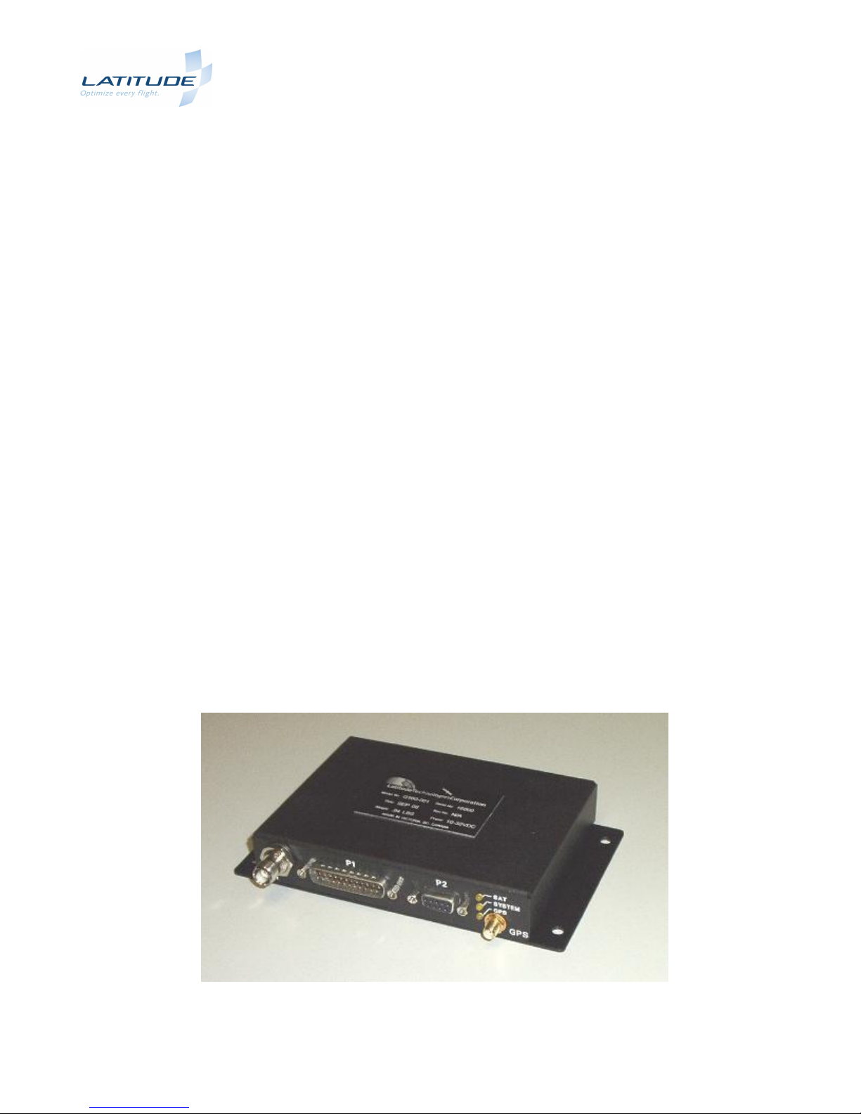
1.4. Equipment Description
The S100 provides complete tracking and data telemetry in a small and light package.
Page 6 of 32 S100-400, R2.01
Figure 1 - SkyNode S100 Tracker

SkyNode® S100 Installation and Operation Manual
1.5. Equipment Limitations
Although there is no specific equipment limitation, the installer should refer to the installation
recommendations of Section 4 and the Environmental Qualification Table of Appendix C.
1.6. Safety Precautions
There is no specific safety precaution as such, associated with this equipment.
2. Referenced Documents
a) RTCA DO-160E, Environmental Conditions and Test Procedures for Airborne Equipment,
2004-12-09
b) FAA AC43.13-1B, Acceptable Methods, Techniques, and Practices - Aircraft Alterations,
2008-03-03
Page 7 of 32 S100-400, R2.01

SkyNode® S100 Installation and Operation Manual
3. SPECIFICATIONS
3.1. Dimensions
See Figure 2 below.
3.2. Electrical Specifications
Power requirement: +12.0 VDC or +28VDC nominal
Input Current: 0.050 A Standby
(at 28VDC) 0.160 A Transmit/Receive (Average)
0.500 A Transmit (Peak)
3.3. Physical Specifications
Length: 6.80 inches (17.3cm)
Width: 4.00 inches (10.2cm)
Height: 1.10 inches (2.8 cm)
Weight: 0.94 lbs (426 g)
Mounting: Any direction. Provide access for visibility of Status Indicators
for Troubleshooting.
Material/Finish: Chassis and cover are 5052-H32 brushed aluminum with black
textured powder coat finish.
Cooling: Convection cooling only. No forced cooling required.
3.4. Environmental Specifications
See Appendix C
3.5. Part Numbers
The following Part Numbers are applicable to this Installation Manual
S100 Tracker P/N S100-001
Page 8 of 32 S100-400, R2.01

SkyNode® S100 Installation and Operation Manual
QTY
LATITUDE
PART NUMBER
DESCRIPTION
1
CN054
DB25 Backshell, plastic
25
CN057
DB25-F 22 AWG crimp socket pins, machined, 109 series
1
CN058
DB25-F connector, crimp socket housing, 109 series
1
CN046
SMA plug, straight crimp for RG-400 cable (M39012/55-4502)
1
CN048
TNC, straight, plug, for RG400 cable (M39012/30-0503)
1
550-0101
Ziploc bag, 2" x 3"
1
550-0103
Ziploc bag, 4" x 6"
QTY
LATITUDE
PART NUMBER
DESCRIPTION
1
CN054
DB25 Backshell, plastic
25
CN057
DB25-F 22 AWG crimp socket pins, machined, 109 series
1
CN058
DB25-F connector, crimp socket housing, 109 series
1
CN047
SMA plug, right angle, crimp for RG-400 cable (M39012/56-
4502)
1
CN049
TNC, right angle, plug, for RG400 cable (M39012/26-0503)
1
550-0101
Ziploc bag, 2" x 3"
1
550-0103
Ziploc bag, 4" x 6"
3.6. Optional Latitude Kits Part Numbers
The following Optional Part Numbers Kits can be ordered from Latitude Technologies Corp.
The KT006 Kit is comprised of the following parts:
Table 1- Latitude Technologies KT006 Kit
The KT007 Kit is comprised of the following parts:
Table 2 - Latitude Technologies KT007 Kit
Page 9 of 32 S100-400, R2.01
SkyNode® S100 Installation and Operation Manual
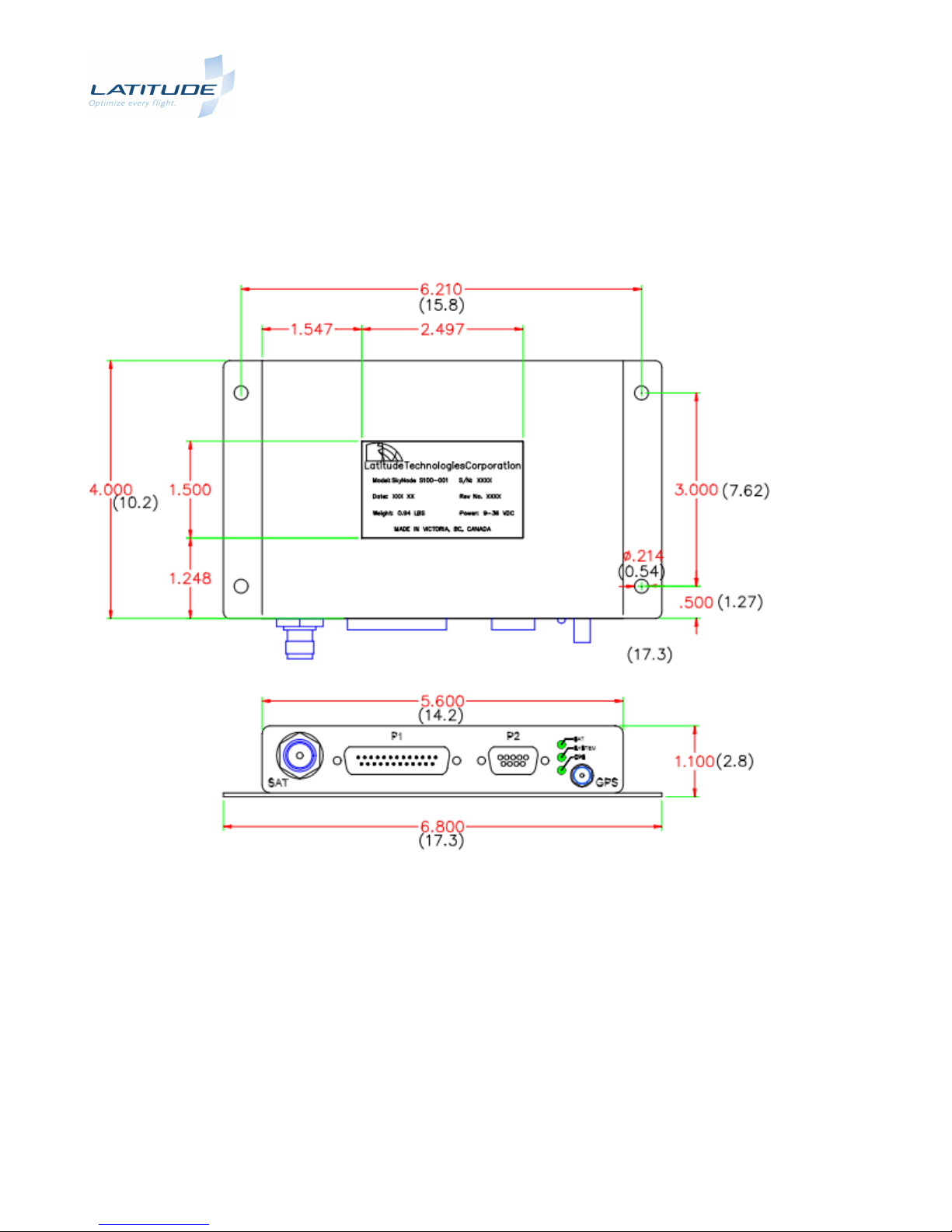
3.7. S100 Dimensions
Dimensions are provided in inches.
Page 10 of 32 S100-400, R2.01
Figure 2 - S100 Outline Drawing
 Loading...