


®
English
O p e r a t i n g M a n u a l
MODEL. “LINEA” - “FB 70” / VERSION. “EE” - “AV”
C h a p t e r s |
|
|
1. |
General warnings and safety specifications |
pag. 3 |
2. |
Definition of available models |
pag. 4 |
3. |
Installation |
pag. 7 |
4. |
Operating the machine and preparing coffee |
pag. 9 |
5. |
Preparing other hot drinks |
pag. 12 |
6. |
Maintenance and weekly cleaning operations |
pag. 13 |
7. |
De-commissioning and demolition |
pag.14 |
8. |
History and use of the La Marzocco |
|
|
coffee machines |
pag. 15 |
VIA BOLOGNESE 68 PIAN DI SAN BARTOLO 50010 FIRENZE, ITALY
LA MARZOCCO s.r.l. T: +39.055.401.390 F: +39.055.401.349
E-MAIL: MARZOCCO@WEBITALY.COM - WWW.LAMARZOCCO.COM

1. General Warnings and Safety Specifications
1)This operating manual is an integral and essential part of the product and must be supplied to users. Users are asked to read the enclosed warnings carefully, as they provide valuable information concerning safety during installation, operation and maintenance.
This manual must be kept in a safe place and be available for consultation to new and experienced users alike.
2)Make sure of the product’s integrity by inspecting the packaging, making sure it presents no signs of damage which might have affected the enclosed machine.
3)Check the machine’s integrity after having carefully removed the packaging.
Notes 2 and 3:
in case of doubt, do not go on any further and contact your dealer or retailer immediately. They will send out specialized personnel authorized to do work on the machine.
4)Packaging (boxes, plastic bags, foam parts and whatever else) must not be left around within easy reach of children, due to the potential danger it represents, nor be discarded in the environment.
5)Check to see that data on the rating plate correspond to those of the mains electrical supply which the machine will be hooked up to.
The installation must be done according to current regulations and to the manufacturer’s instructions, and must be performed by qualified and authorized personnel.
Incorrect installation may be cause for injury/damages to people, animals or objects, for which the manufacturer shall not be held responsible.
Safe electrical operation of this device will be achieved only when the connection to the power outlet has been completed correctly and in observance of current safety regulations, and particularly by grounding the unit very carefully. Make sure grounding has been done correctly as it represents a fundamental safety requirement and, in case of doubt, do not hesitate to have qualified personnel check such connection.
Furthermore, you must ensure that the capacity of the available electrical system is suitable for the maximum power consumption indicated on the rating plate; make sure also that electrical cables are of a suitable size.
We do not recommend using adapters, multiple plugs and/or extension cords. If you cannot avoid using them, make sure that they are exclusively of the kind which conforms to current safety regulations, being careful not to exceed the power and current ratings indicated on such adapters and extension cords.
6)This device must be used exclusively for the functions it has been designed and built for. Any other application is inappropriate and dangerous. The manufacturer shall not be held responsible for any damages caused by improper and irrational use.
7)Using any electrical device requires that certain fundamental rules be observed.
In particular:
-do not touch the device while having wet or humid
hands and feet;
-do not use the device while having no shoes on your feet;
-do not use extension cords in bath or shower rooms;
-do not unplug the device from the power outlet by pulling on the power supply cable;
-do not expose the device to atmospheric agents (rain, sun, etc.);
-do not allow children or untrained people to use this device;
-do not clean the control panel with a wet cloth since it is not watertight.
8)Before carrying out any maintenance and/or cleaning operations, turn the main switch, which is located on the machine, to the “0” position, and disconnect the machine from the electrical network by unplugging the cord or by switching off the relative circuit breaker. For any cleaning operation, follow exclusively the instructions contained in this manual.
9)In case the machine is operating in a faulty manner or breaks down, disconnect it from the electrical network (as described in the preceding point) and close the water supply tap. Do not attempt to repair it, and contact qualified and authorized professionals. Any repairs must be performed exclusively by the manufacturer or by an authorized centre using only original parts. Non compliance with the above forfeits the warranty and could compromise the safe operation of the machine.
10)You should plan to make use of an omnipolar connector during installation, as required by current safety regulations, complete with fuses suitable to bear the power of the machine being connected.
11)In order to avoid dangerous overheating problems, it is recommended that the power supply cable be fully unfurled.
12)Do not obstruct air intake and exhaust grilles and, in particular, do not cover the cup warmer tray with cloths or other items.
13)The machine’s power supply cable must not be replaced by users, as also specified on the rating plate located near the outlet of such cable, on the body. In case the cable gets damaged, shut off the machine (as described in point 8) and close off the water supply; to replace it, contact qualified professionals exclusively.
CAUTION:
As already mentioned in the preceding notes, the manufacturer shall not be held responsible for damages to objects, animals and/or people whenever the machine has not been installed according to the instructions contained in this manual, and is not used to do what it was designed for (i.e. preparing coffee and hot drinks).
English
3
hsilgnE
2. Definition of Available Models
This operating manual refers exclusively to the following models, of our own manufacture:
Mod. EE - Mod. AV with 1, 2, 3 e 4 groups
Everything set out in this operating manual is also valid for the “FB70” series. The only differences are the external dimension of the machine.
COMMON DIMENSIONS AND WEIGHTS FOR THE |
COMMON DIMENSIONS AND WEIGHTS FOR |
LINEA SERIES |
THE FB70 SERIES |
|
1 gr. |
2 gr. |
3 gr. |
4 gr. |
|
|
|
|
|
A [mm] |
420 |
420 |
420 |
420 |
|
|
|
|
|
B [mm] |
520 |
520 |
520 |
520 |
|
|
|
|
|
C [mm] |
490 |
690 |
930 |
1170 |
|
|
|
|
|
WEIGHT [kg] |
44 |
58 |
74 |
92 |
|
|
|
|
|
|
2 gr. |
3 gr. |
4 gr. |
|
|
|
|
A [mm] |
450 |
450 |
450 |
|
|
|
|
B [mm] |
610 |
610 |
610 |
|
|
|
|
C [mm] |
840 |
1080 |
1330 |
|
|
|
|
WEIGHT [kg] |
58 |
74 |
92 |
|
|
|
|
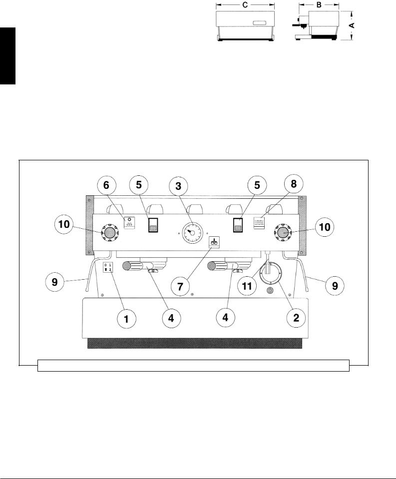
fig. 1 - Model EE with 1, 2, 3 and 4 groups
Legend |
|
|
|
|
1) |
Main switch |
7) |
Hot water switch |
|
2) |
Water level sight glass |
8) |
Emergency button for loading water |
|
3) |
Pressure gauge |
9) |
Steam nozzle |
|
4) |
Coffee groups |
10) |
Steam knob |
|
5) |
Coffee brewing control panel |
11) |
Hot water nozzle |
|
6) |
Cup warmer switch |
|
|
|
4

General description
The model EE machine is built in the 1, 2, 3, and 4 group versions and is essentially composed of the following parts:
1.Water boiler (produces steam and hot water);
2.Coffee (“saturation”) boiler;
3.Brewing groups;
4.Cover;
5.Motor pump;
6.Water purifier.
Description of the various parts
1. Water Boiler
It consists of a cylindrical tank, of varying length according to the number of coffee groups, which is made of Aisi 304 stainless steel. Each unit is subjected to a hydraulic test, at a pressure of 3 bar, and has an operating pressure of 1.5 bar. In the following, you will find a list of effective volumes and power ratings according to the number of groups installed:
1 group |
3,5 litres |
1300 Watts |
2 groups |
7 litres |
2000 Watts |
3 groups |
11 litres |
3000 Watts |
4 groups |
15 litres |
3800 Watts |
3. Brewing Groups
They consist of a die-cast block made of nickel-plated brass, on which to install the filter-holder handle used to hold the ground coffee; the espresso flows from the block, through a spout, into the cup(s) after the brewing button has been pressed.
4. Cover
It consists of a painted and stainless sheet steel body. The structure has been the object of specific studies to provide good aesthetics, to lower ergonometric costs for the operator and to reduce the chance of damage to a minimum.
5. Motor Pump
The pump, which is of the “positive-displacement” type, is installed on the water supply tubing and is set-up to operate anytime the coffee groups are activated, and through an electric level gauge whenever the water boiler needs to be replenished.
6. Water Purifier
It is of the “ion exchange” resin type, for water softening purposes. Resins must be regenerated weekly according to the instructions and the diagrams shown on the labels affixed to the purifiers themselves. See Chapter 6.
Covers are installed at either end of the cylindrical tank and on one of them there is a housing for the water heating and vapourizing electrical elements, which allow reaching operating pressure within 25’ approximately. Operating pressure is maintained by a manostat. The water boiler has various fittings used for safety devices, for supplying hot water and steam, and for the power supply.
2. Coffee Boiler
Each unit is subjected to a hydraulic test, at a pressure of 16 bar, and has an operating pressure of 9 bar. In the following, you will find a list of effective volumes and power ratings according to the number of groups installed:
1 group |
1.8 litres |
1000 |
Watts |
2 groups |
3.4 litres |
1400 |
Watts |
3 groups |
5.0 litres |
1600 |
Watts |
4 groups |
3.4 + 3.4 litres |
1400 |
+ 1400 Watts |
(2 boilers installed)
It consists of a cylindrical tank, of varying length according to the number of coffee groups, which is made of Aisi 304 stainless steel.
Covers are installed at either end of the cylindrical tank and on one of them there is a housing for the water heating and vapourizing electrical elements, regulated by a precision thermostat with a dT of ± 1°C wich keeps the water temperature constant. This temperature can be adjusted to reach optimal temperature according to the type of coffee blend being used. The groups are installed on the boiler.
English
5

hsilgnE
fig. 2 - MODEL AV with 1, 2, 3 and 4 groups
Legend
1.Main switch
2.Water level sight glass
3.Pressure gauge
4.Coffee groups
5.Coffee dispensing control panel
6.Cup warmer switch
7.Hot water switch
8.Emergency button for loading water
9.Steam nozzle
10.Steam knob
11.Hot water nozzle
12.Key operated switch to enable dosage programming Not available in Version 3D5
13.Manual brew switch
General Description
The model AV machine is built in the 1, 2, 3, and 4 group versions and is essentially composed of the same parts as model EE.
This model differs from model EE in that it allows the operator to choose four different quantities of water for brewing coffee. Each group, therefore, is provided with a 5 button control panel, allowing a combination of:
-a quantity of water for one normal (short) coffee;
-a quantity of water for one tall coffee;
-a quantity of water for two normal coffees;
-a quantity of water for two tall coffees.
The fifth button is used to program the other ones, as we shall see later, and as an on-off switch for continuous brewing.
Coffee brewing control panel for the AV model
6

3. Installation
English
WATER PURIFIER
MOTOR PUMP
fig. 3
Legend
380 Volt cable
220 Volt cable
Water tubing
Water supply tubing
Drain tubing
7
 Loading...