


manual
linea & fb70
The Linea’s straight lines and simple charm occupy many cafes, roasters and chains, whose names define the industry. The Linea is the classic La Marzocco machine that has long supported and helped to develop the specialty coffee industry since the 1990s.
It is a heavy duty workhorse that performs reliably in the highest volume settings. Tried and true machine, the Linea is perfect for your new cafe, bar, or restaurant.
|
|
|
|
|
|
|
|
|
|
|
|
|
|
|
|
|
|
|
|
|
|
|
|
|
|
|
|
|
|
|
EN |
linea & fb70 |
|
||
|
|
|
|
|
||||
|
|
|
|
|
|
|
||
|
|
|
|
|
|
Operating Manual V1.1 - 11/2014 |
|
|
|
|
|
|
|
|
|
||
|
|
|
|
|
|
Chapters |
|
|
|
|
|
|
|
|
1. |
General Warnings and Safety Specifications |
page 2 |
|
|
|
|
|
|
2. |
Definition of Available Models |
page 4 |
|
|
|
|
|
|
3. |
Installation |
page 7 |
|
|
|
|
|
|
4. Machine Operation and Coffee Preparation |
page 11 |
|
|
|
|
|
|
|
5. |
PID Temperature Controller |
page 16 |
|
|
|
|
|
|
6. Dispensing Steam and Hot Water |
page 18 |
|
|
|
|
|
|
|
7. |
Maintenance and Periodic Cleaning Operations |
page 19 |
|
|
|
|
|
|
8. De-commissioning and Demolition |
page 21 |
|
|
|
|
|
|
|
9. Mandatory Maintenance and Check-up Operations |
page 22 |
|
La Marzocco S.r.l.
Via La Torre 14/H
Località La Torre
50038 Scarperia e San Piero (Firenze) - ITALIA
www.lamarzocco.com
info@lamarzocco.com
T: +39 055 849 191
F: +39 055 849 1990
certifications available:
1. General Warnings and Safety SpecificationsEN
WARNING
THIS MACHINE IS FOR PROFESSIONAL USE ONLY AND SHOULD BE INSTALLED IN LOCATIONS WHERE ITS USE AND MAINTENANCE IS RESTRICED TO TRAINED PERSONNEL. CHILDREN ARE FORBIDDEN TO OPERATE OR PLAY WITH THE MACHINE.
1)Thisoperatingmanualisanintegraland essential part of the product and must be supplied to users. Users are asked to read the enclosed warnings carefully, as they provide valuable information concerning safety during installation, operation and maintenance.
This manual must be kept in a safe place and be available for consultation to new and experienced users alike.
2)Make sure of the product’s integrity by inspecting the packaging, making sure it presents no signs of damage which might have affected the enclosed machine.
3)Check the machine’s integrity after having carefully removed the packaging. When in doubt, do not proceed, contact your dealer or retailer immediately. They will send out specialized personnel
authorized to do work on the machine.
4) Packaging (boxes, plastic bags, foam parts and whatever else) must not be left around within easy reach of children, due to the potential danger it represents, nor be discarded in the environment.
5) Check to see that data on the rating plate correspond to those of the mains electricalsupplytowhichthemachinewill be hooked up.
The installation must be done according to current regulations and to the manufacturer’s instructions, and must be performed by qualified and authorized personnel. This machine should not be installed in kitchens.
Incorrect installation may be cause for injury/damage to people, animals or objects, for which the manufacturer shall not be held responsible.
Safe electrical operation of this device will be achieved only when the connection to the power outlet has been completed correctly and in observance of current safety regulations, and particularly by grounding the unit very carefully. Make sure grounding has been done correctly as it represents a fundamental safety requirement and, in case of doubt, do not hesitatetohavequalifiedpersonnelcheck such connection.
Furthermore, you must ensure that the capacity of the available electrical system is suitable for the maximum power consumptionindicatedontheratingplate; makesurealsothatelectricalcablesareof a suitable size.
We do not recommend using adapters, multiple plugs and/or extension cords. If you cannot avoid using them, make sure
that they are exclusively of the kind which conforms to current safety regulations, beingcarefulnottoexceedthepowerand currentratingsindicatedonsuchadapters
and extension cords.
6)Thisdevicemustbeusedexclusivelyfor thefunctionsithasbeendesignedandbuilt for. Any other application is inappropriate and dangerous. The manufacturer shall not be held responsible for any damage caused by improper and irrational use.
This equipment must be installed to comply with applicable federal, state or local plumbing codes.
7)Usinganyelectricaldevicerequiresthat certain fundamental rules be observed. In particular:
• do not touch the device when you have wet or humid hands and feet;
• do not use the device without shoes on your feet;
• do not use extension cords in bath or shower rooms;
• do not unplug the device from the power outlet by pulling on the power supply cable;
•donotexposethedevicetoatmospheric agents (rain, sun, etc.);
• do not allow children or untrained
people to use this device;
•do not clean the control panel with a wet cloth since it is not watertight.
2
EN
8) Before carrying out any maintenance and/or cleaning operations, turn the main switch, which is located on the machine, to the “0” position, and disconnect the machine from the electrical network by unplugging the cord or by switching off the relative circuit breaker. For any cleaning operation, follow exclusively the
instructions contained in this manual.
9) When the machine is operating in a faulty manner or breaks down, disconnect it from the electrical network (as described in the preceding point) and close the water supply tap. Do not attempt to repair it, and contact qualified and authorized professionals. Any repairs must be performed exclusively by the manufacturer or by an authorized centre using only original parts. Non compliance with the above forfeits the warranty and could compromise the safe operation of the machine.
10) You should plan to make use of an omnipolar connector during installation, as required by current safety regulations, complete with fuses suitable to bear the
power of the machine being connected.
11) In order to avoid dangerous overheating problems, it is recommended that the power supply cable be fully unfurled.
12) Do not obstruct air intake and exhaust
grilles and, in particular, do not cover the cup warmer tray with cloths or other
items.
13) The machine’s power supply cable must not be replaced by users, as also specified on the rating plate located near the outlet of such cable, on the body. If the cable gets damaged, shut off the machine (as described in point 8) and close off the water supply; to replace it,
contactexclusivelyqualifiedprofessionals.
CAUTION
AS ALREADY MENTIONED IN THE PRECEDING NOTES, THE MANUFACTURER SHALL NOT BE HELD RESPONSIBLE FOR DAMAGE TO OBJECTS, ANIMALS AND/OR PEOPLE WHENEVER THE MACHINE HAS NOT BEEN INSTALLED ACCORDING TO THE INSTRUCTIONS CONTAINED IN THIS MANUAL, AND IS NOT USED TO DO WHAT IT WAS DESIGNED FOR
(i.e. PREPARING COFFEE AND HOT DRINKS).
WARNING
THIS MACHINE IS NOT SUITABLE FOR OUTDOOR USE. JETS OF WATER SHOULD NOT BE USED TO CLEAN THE MACHINE,
NOR SHOULD IT BE PLACED
WHERE WATER JETS ARE USED.
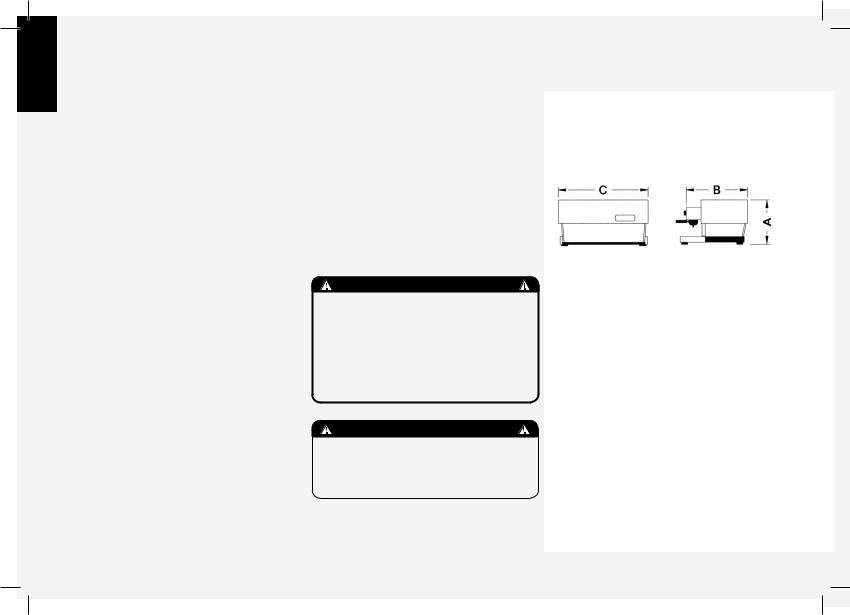
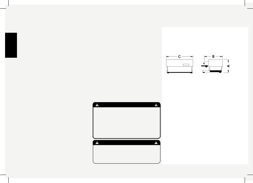
Everything set out in this operating manual is also valid for the “FB/70” series.
The only differences are the external dimensions of the machine.
COMMON DIMENSIONS AND WEIGHTS FOR THE LINEA SERIES
LINEA |
1 gr |
2gr |
3gr |
4gr |
A cm/inch |
45.5/18 |
45.5/18 |
45.5/18 |
45.5/18 |
B cm/inch |
56/22 |
56/22 |
56/22 |
56/22 |
C cm/inch |
49/20 |
69/28 |
93/37 |
117/46 |
WEIGHT kg/lb |
44/97 |
58/128 |
74/163 |
92/203 |
COMMON DIMENSIONS AND WEIGHTS FOR THE FB/70 SERIES
FB/70 |
2gr |
3gr |
4gr |
A cm/inch |
45.5/18.5 |
45.5/18.5 |
45.5/18.5 |
B cm/inch |
64/25.5 |
64/25.5 |
64/25.5 |
C cm/inch |
84/33 |
108/42.5 |
135/52.25 |
WEIGHT kg/lb |
58/128 |
74/163 |
92/203 |
3
2. Definition of Available ModelsEN
This operating manual refers exclusively to the following models, of our own manufacture:
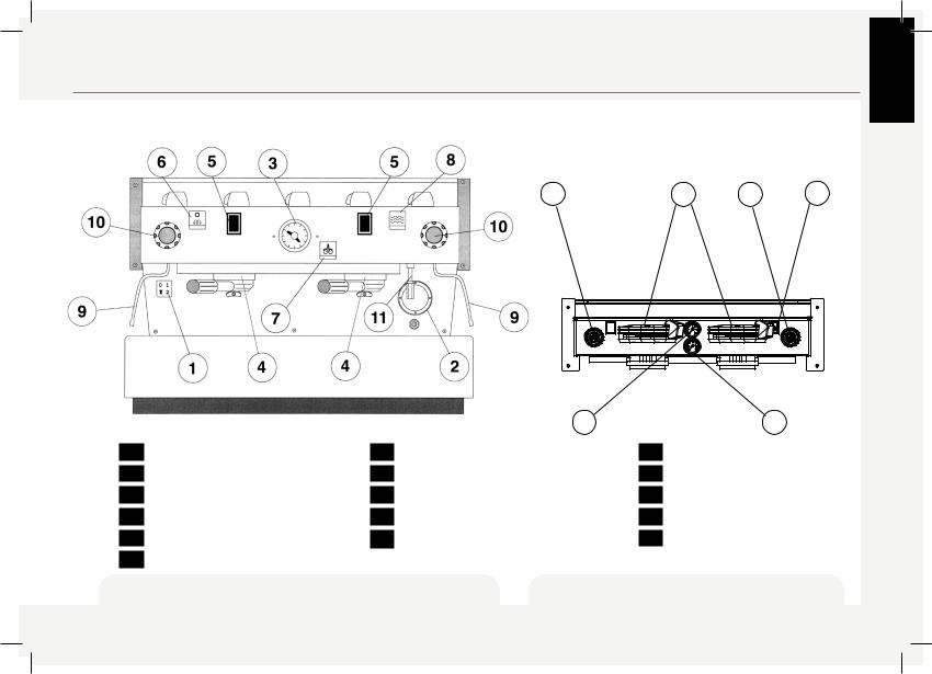
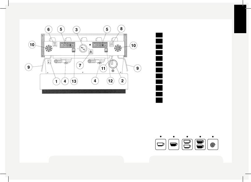
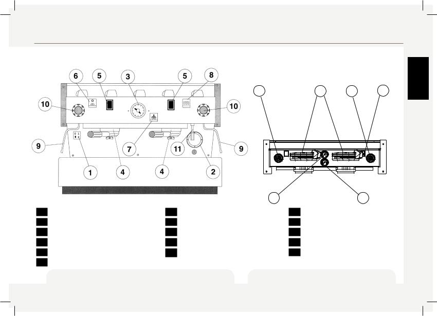
EE Model, AV Model, PADDLE Model with 1, 2, 3 and 4 groups
2 |
1 |
2 |
5 |
Legend |
|
3 |
|
4 |
|
|
|
|
|
||
1 |
Main Switch |
7 |
Hot water switch |
1 |
Group lever |
2 |
Water level sight glass |
8 |
Manual fill switch |
2 |
Steam knob |
3 |
Pressure gauge |
9 |
Steam nozzle/wand |
3 |
Pressure gauge steam boiler |
4 |
Coffee groups |
10 |
Steam knob |
4 |
Pressure gauge coffee boiler |
5 |
Coffee brewing control switch |
11 |
Hot water nozzle |
5 |
Manual fill switch |
6 |
Cup warmer switch (non-UL machines) |
|
|
|
|
fig. 1 - EE Model available with 1, 2, 3 and 4 groups fig. 2 - Front panel of PADDLE model
available with 1, 2, 3 and 4 groups
4
EN
General description
The models AV, EE and PADDLE are built in the 1, 2, 3 and 4 group versions and are essentially composed of the following parts:
1.Water boiler (produces steam and hot water);
2.Coffee (“saturation”) boiler;
3.Brewing groups;
4.Exterior;
5.Motor pump;
Description of the various parts
1. Steam Boiler
The steam boiler consists of a cylindrical tank, of varying length according to the number of coffee groups, which is made of stainless steel. Each unit is subjected to a hydraulic test, at a pressure of 3 bar, and has an operating pressure of 1.5 bar. In the following, you will find a list of effective volumes and standard power
ratingsaccordingtothenumberofgroups installed:
1 group |
3.5 |
litres |
1300 Watts |
2 groups |
7 |
litres |
2000 Watts |
3 groups |
11 |
litres |
3000 Watts |
4 groups |
14.5 litres |
3800 Watts |
|
Higher powered heating elements are available for steam boilers in some markets.Coversareinstalledateitherend of the cylindrical tank and on one of them there is a housing for the water heating andvapourizingelectricalelements,which allow reaching operating pressure within
25’ approximately. Operating pressure is maintained by a pressure switch. The water boiler has various fittings used for safety devices, for supplying hot water
and steam, and for the power supply.
2. Coffee Boiler
The coffee boiler is subjected to a hydraulic test, at a pressure of 16 bar, and has an operating pressure of 9 bar. In the following, you will find a list of effective volumes and power ratings according to
the number of groups installed:
1group |
1.8litres |
1000Watts |
2groups |
3.4litres |
1400Watts |
3groups |
5.0litres |
1600or1900Watts |
4groups |
3.4+3.4litres 1400+1400Watts |
|
|
(2boilersinstalled) |
|
It consists of a cylindrical tank, of varying length according to the number of coffee groups, which is made of stainless steel. Covers are installed at either end of the cylindrical tank and on one of them there is a housing for the water heating and vapourizing electrical elements, regulated byaprecisionPIDControllerwithadTof± 0.5°C which keeps the water temperature constant. This temperature can be adjusted to reach optimal temperature according to the type of coffee blend being used. The groups are welded to the
boiler.
3. Brewing Groups
The brew groups are made of stainless steel, in which you engage the portafilter
used to hold the ground coffee; the espresso flows from the group, through a spout, into the cup(s) after the brewing button has been pressed.
4. Exterior
The exterior consists of painted and stainless sheet steel panels. To provide goodaesthetics,tooptimizeergonometrics fortheoperatorandtoreducethechance of damage to a minimum.
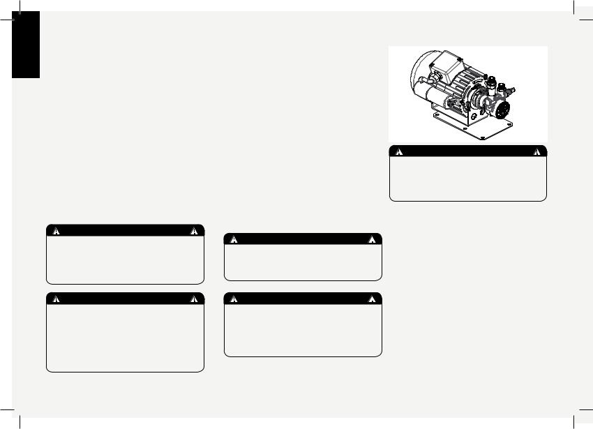
5. Motor Pump
The rotary vane pump, is installed on the water supply tubing and is set up to operate anytime the coffee groups are activated, and through an autofill system whenever the water boiler needs to be
replenished.
WARNING
The coffee boiler and steam boiler contain water at elevated temperature. Water temperature over 125°F/52°C can cause severe burns instantly or death from scalding (Coffee boiler 200°F/93.3°C-Steam boiler 260°F /127°C)
WARNING
This appliance is not intended for use by persons (including children) with reduced physical, sensory or mental capabilities, or lack of experience and knowledge, unless they have been given supervision or instruction concerning the use of the appliance by a person responsible for their safety.
5
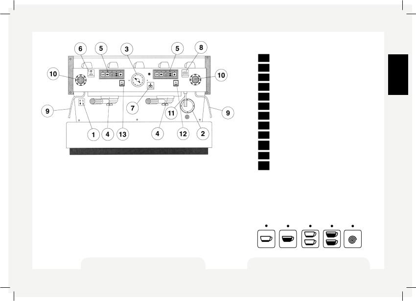
Legend
|
1 |
Main Switch |
|
2 |
Water level sight glass |
|
3 |
Pressure gauge |
|
4 |
Coffee groups |
|
5 |
Coffee dispensing control panel (AV model) |
|
6 |
Cup warmer switch (non-UL machines) |
|
7 |
Hot water switch |
|
8 |
Manual fill switch |
|
9 |
Steam nozzle/wand |
|
10 |
Steam knob |
|
11 |
Hot water nozzle |
General Description |
12 |
Manual brew switch |
The AV model machine is built in the 1, 2, 3, and 4 group versions and is essentially composed of the same parts as EE model.
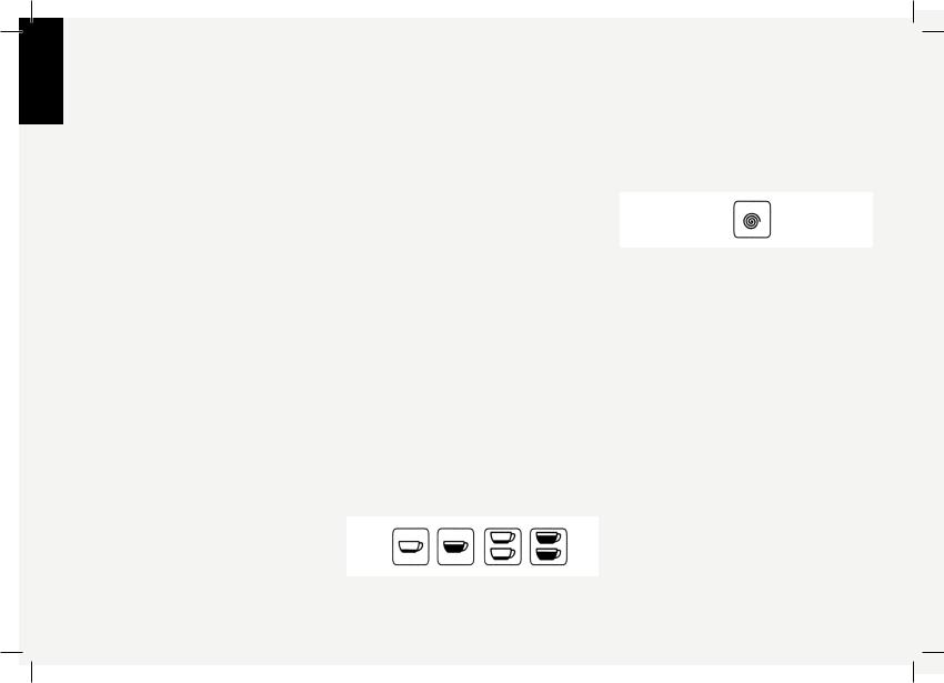
This model differs from EE model in that it allows the operator to choose four different quantities of water for brewing coffee. Each group, therefore,isprovidedwitha5buttoncontrolpanel,allowingacombinationof:
-a quantity of water for one normal espresso coffee;
-a quantity of water for one tall coffee;
-a quantity of water for two normal coffees;
-a quantity of water for two tall coffees.
The fifth button is used to program the other ones, as we shall see later, and as an on-off switch for continuous brewing.
EN
Fig. 3 - AV model available with |
Coffee brewing control panel for the AV model |
1, 2, 3 and 4 groups |
6 |
|
EN
|
|
|
|
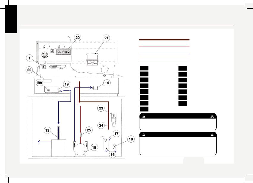
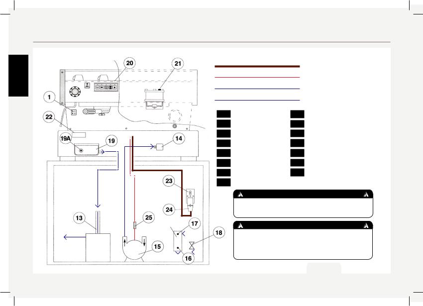
3. Installation |
|
Legend |
|
|
|
|
|
|
|
380/220/200 Volt cable |
|
|
|
|
220/200 Volt cable |
|
|
|
|
Water tubing |
|
|
|
|
Drain tubing |
|
1 |
Main Switch |
19A |
Expansion valve |
|
13 |
Drain piping |
20 |
Group cover |
|
14 |
Terminal |
21 |
Bleed screw |
|
15 |
Motor pump |
22 |
PID Temperature Controller |
|
16 |
Filter outlet |
23 |
Switch (not provided) |
|
17 |
Filter inlet |
24 |
Plug (not provided) |
|
18 |
Tap |
25 |
Connectors |
not provided |
19 |
Drain wells |
|
|
|
|
|
|
|
|
|
|
|
WARNING |
|
|
|
|
|
|
|
not provided |
THE COFFEE MACHINE MUST BE PLACED IN A |
|
|
|
|
|
|
|
|
HORIZONTAL POSITION ON A COUNTER HIGHER |
||
|
|
|
|
|
|
|
|
|
THAN 80CM FROM THE GROUND. |
|
|
WATER FILTER |
WARNING |
||||||
|
|
(not provided) |
|||||||
|
|
|
|
|
|
|
|
|
THE MACHINE IS INTENDED TO BE PERMANENTLY |
|
|
|
|
|
|
|
|
|
CONNECTED TO FIXED WIRING, AND IT IS ADVISABLE |
motor |
|
|
|
|
|
|
THAT A RESIDUAL CURRENT DEVICE (RCD) WITH |
||
|
|
|
|
|
A RATED RESIDUAL OPERATING CURRENT NOT |
||||
pump |
|
|
|
|
|
|
|||
|
|
|
|
|
|
EXCEEDING 30MA IS INSTALLED. |
|||
|
|
|
|
|
|
|
|
|
|
Fig. 4
7
MODELS “EE” “AV” and “PADDLE” 1, 2, 3 and 4 groups
1) Accessories
Check the package to make sure that the following accessories are included:
•a number of 1-dose and 2-dose portafilters according to the number of groups;
•replacement 1-dose and 2-dose filter baskets
•1 tamper
•1 blind filter
•cleaning detergent, for the groups
•3 stainless steel braided hoses for water connections
•1,5 mt of reinforced plastic tubing for drainage
•1 hose clamp
WARNING
At each installation, the machine should be equipped with a new set of tubes for plumbing and related gaskets.
In order to proceed with installation, it is necessarythatthefollowing areavailable:
•Pipes carrying drinking water with a 3/8”G (BSP) end connection; (3/8” Compression for USA and Canada)
•Electrical Supply according to the specification of the espresso machine purchased (not all specifications are available in all markets):
→ Single/Three phase 220VAC - 50/60 Hz electrical connection with ground, protected receptacle and approved circuit breaker
→Single phase 200VAC - 50/60 Hz electrical connection with ground, protected receptacle and approved circuit breaker
→Three-phase, 380VAC - 50/60 Hz electrical connectionwithneutral+ground,nearthe bench on which the machine is installed and terminating in a suitable protected fivepole receptacle equipped with an approved circuit breaker
• Waste water drain system
Note:
•The drinking water mains valve and the circuit breakers for the electrical system need to be located in the most convenientpositionfortheoperatorto access them easily and quickly.
•Themachineshouldbeplacedonaflat counterandmustbeplacedinsettings with the following temperatures:
Minimum room temperature: 5°C/41°F Maximumroomtemperature:32°C/89°F
•If the machine has been temporarily housed in settings with a room temperature of less than 0°C/32°F, please contact a service technician prior to use.
•Water pressure supply must be between 2 and 6 bar.
WARNING |
EN |
|
|
Hazardous voltage disconnect from |
|
power supply before servicing |
|
2) Water supply connection
In order to connect the machine up to the water mains proceed according to the indications given in the chapter about Installation and in compliance with any local/national safety standards of the location in which the machine is being installed.
To guarantee a correct and safe functioning of the machine and to maintain an adequate performance level and a high quality of the beverages being brewed it is important that the incoming water be of a hardness greater than 9°f (90ppm, 5°d) and less than 15°f (150ppm, 8.4°d), pH should be between 6.5 and 8.5 and the quantity of chlorides be less than 50mg/l . Respecting these values allows the machine to operate at maximum efficiency. If these parameters are not present, a specific filtration device should be installed, while always adhering to the local national standards in placeregarding potable water.
Then connect the inlet of the water filter/ softener (if present) to the drinking water supply using one of the supplied stainless steel braided hoses. Before connecting the filter to the water pump, flush the
8
EN
water supply line and the filtration system inordertoeliminateanyresidualparticles which could otherwise get stuck in taps or valvesthuspreventingthemfromworking
properly. Connect the water supply connection of the espresso machine to the water pump outlet using one of the supplied stainless steel braided hoses. Then connect the water pump inlet to the water filter/softener outlet (if present).
Note: Make sure that water supply is always on while the pump is operating, otherwise air can be introduced into the brew boiler causing an undesireable condition and damage to the pump.
3) Electrical connections
caution
Before making any electrical connections make sure that the TWO strain relief connectors are firmly secured to the body of the machine in order to prevent inadvertent stress on the power cables.
WARNING
The manufacturer declines any responsibility for any event leading to liability suits whenever grounding has not been completed according to current local, national, and international regulations and electrical codes, or other electrical parts have been connected improperly.
a) Power supply cord
• This is the main power supply cable that provides power to the entire espresso machine. Therearedifferenttypesofcable based upon the electrical requirements of the espresso machine purchased:
→200/220VAC 1 Phase 3-core cable with 2.5/4/6/10mm2 cross section or AWG 12/10/8 (for UL version), secured to espresso machine via a strain relief connector
→220VAC 3 Phase 4-core cable with 4 mm2 cross section for versions with 1, 2 , 3 and 4 groups secured to espresso machine via a strain relief connector
→380 VAC 3 Phase 5-core cable with 2.5/6 mm2crosssectionforversions with1,2,3and 4 groups secured to espresso machine via a strain relief connector.
WARNING
- U.S.A. And canada only - Do not connect to a circuit operating at more than 150 v to ground
WARNING
In order to prevent cracks or leakage: do not store or install the coffee machine in places where temperature may cause
water in boiler or hydraulic system to freeze.
WARNING
The motor pump must be situated close to the machine in an accessible place for maintenance but not for accidental interference and where there is an optimal air circulation
b) Water pump motor power cord
This is the power supply for the water pump motor. The internal electronics will switch the pump motor on when needed.
• 3-core cable with 1.5 mm2 cross section or3-coreAWG16(forULversion)secured to espresso machine via a strain relief connector.
4) Waste water drain connection
The espresso machine drain is to be connected by means of the included reinforced plastic tubing. Connect one end of the reinforced plastic tubing to the drain hose connection on the left side of the espresso machine, secure with included hose clamp.
9
Connect the other end to a suitable waste water collection system.
Incasesuchasystemisnotavailable,andif acceptable according to local regulations, drained liquids may be collected in a suitable bucket and any necessary drain pipe extensions shall be made using steellinedPVCtubingandsuitablehoseclamps.
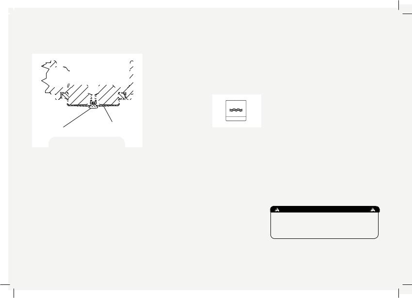
4. Machine Operation and Coffee PreparationEN
Onceinstallationhasbeencompleted,you |
inflowing water will compress the air in |
can proceed to hook up the filter holders |
the boiler it will be necessary, in order to |
(Fig. 5) called portafilters, together with |
completely “saturate” the boiler-groups |
their filters, to the bottom of the groups |
assembly, to remove the group cover |
by rotating them from left to right. Before |
plate (part 20 Fig. 4) and unscrew the |
operating the various switches and thus |
small bolt (part 21) called bleed screws |
powering up the heater elements, fill up |
a little way so as to allow air to escape |
the boiler tanks with water, as follows: |
until a few drops of water leak out (see |
1. COFFEE BOILER |
diagram below). This should be repeated |
The water flows inside the coffee boiler |
for each group, then tighten the bleed |
directly, as soon as the water system |
screws again and reinstall the cover. |
and purifier taps are opened. Since the |
|
fig. 5 - Portafilter (see also part. 4, fig. 1 or 3) |
|
Saturation of group via “bleed screw” |
|
|
|
10
EN
2) STEAM BOILER
By turning the main switch (part 1) to position “1”, the automatic fill system will be switched on which, by activating the solenoid valve and the motor pump (part 15), will fill the steam boiler up to a predetermined level selected by adjusting the probe inside the boiler itself.
N.B.
Itmayhappenthattheairinsidetheboiler buildsuppressure(whichmaybedetected through the pressure gauge - part 3, Fig 1, 2 or 3) To resolve this, turn the machine off and bleed the air from the groups (see previous page for instructions). Once you have completed these operations, turn the main switch (part 1) to position “2” andwaitfortheboilerstoreachoperating temperature and pressure (which takes from 20 to 35 minutes, depending on the size of machine), which will be subsequently maintained at a constant value automatically.
During this time, the pointer of the lower scale on the pressure gauge (part 3, fig. 1 or 3; or part 4 fig. 2) may reach as high as 11-12 bar; this may occur any time that, while activating the groups, the motor pump forces cold water into the coffee boiler at a pressure of 8-9 bar and, simultaneously, the temperature controller regulating the temperature of 11
the boiler itself switches on the heating elements in order to bring the water contained in such boiler up to operating temperature. However, in this case it is necessary to adjust the expansion valve (Fig. 4, part 19A) in such a way that the pressure may never exceed 12 bar.
Brewing after first installation
Once the first installation procedures are finished, before proceeding with brewing coffee,hotwaterandsteam,pleasefollow these steps:
-Engage the portafilters by inserting themintoeachgroup,brewwaterthrough each group for at least two minutes.
-Being careful to avoid burns, turn on each steam wand for at least one minute.
-Turn on the hot water valve for the time necessary to allow the following quantities of water to be brewed:
At least 1 liter for a 1/2 group machine At least 2 liters for a 3 group machine At least 3 liters for a 4 group machine
COFFEE BREWING BUTTON (fig.1 part 5)
CAUTION
DO NOT REMOVE THE FILTER HOLDER WHILE RELATIVE GROUP IS BREWING HOT LIQUIDS. THE COFFEE BOILER CONTAINS WATER AT ELEVATED TEMPERATURE. WATER TEMPERATURE OVER 125°F / 52°C CAN CAUSE SEVERE BURNS INSTANTLY OR DEATH FROM SCALDING.
For EE model - fig. 1
Take a portafilter and place some ground coffee in the filter itself: the suggested amounts (in grams) to use are lasermarked on the actual filters. Press down on the ground coffee with the supplied tamper and engage the filter holder in the group and then press the switch (part 5) thus allowing coffee to be brewed; when you have obtained your desired amount of coffee, press the switch again (part 5), at which point the machine discharges the pressure built up in the filter holder. The holder may then be removed to proceed with making another coffee, as required.
For PADDLE model - fig. 2
Take a portafilter and place some ground coffee in the filter itself: the suggested amounts (in grams) to use are lasermarked on the actual filters. Press down on the ground coffee with the supplied tamper and engage the portafilter in the group. Move the paddle handle of the
group from right to left (part 1) thus allowing coffee to be brewed; when you have obtained your desired amount of coffee, return the paddle handle back to original position on the right-hand side, at which point the machine discharges the pressure built up in the portafilter. It may then be removed to proceed with making another coffee, as required. In order to pre-infuse the coffee in the filter, once the portafilter has been engaged in the group, move the paddle handle only half way from the right to left for a few seconds, then move all the way to the left inordertobrewyourespresso/s,untilthe desired dose is released in the cup, then turn off by returning the paddle handle to itsoriginalpositionontheright-handside.
For AV model - fig. 3
It is essential to program the quantity of water delivered by performing the followingoperationswiththeutmostcare. In case of doubt or difficulties, please contact our technical service.
COFFEE BREWING CONTROL PANEL (part. 5 fig 3)
Introduction
The coffee metering system is based on the amount of water which will be
delivered onto the ground coffee, already set in the filter and the portafilter, which is measured through a water volume control system, which is located above the group assembly flange, where the group connects to the boiler. Inside each counter there is a paddle wheel (which we shall call wheel for simplicity) which rotates as water flows by.
The sequence of the water cycle is as
follows: |
|
|
group |
|
counter |
|
||
counter |
|
solenoid valve |
|
||
solenoid valve |
|
diffuser |
diffuser |
|
coffee brewing spout |
|
The wheel is designed in such a way as to rotate freely when water is flowing by; it sends 2 signals, every complete rotation, to the electronic module which processes them and activates the solenoid valve relay of the corresponding group, as well as the motor pump relay.
Such electronic module also processes the signal sent by the boiler’s level gauge and consequently activates the relative solenoid valve relay of the same motor pump.
Procedure for programming doses - fig. 3
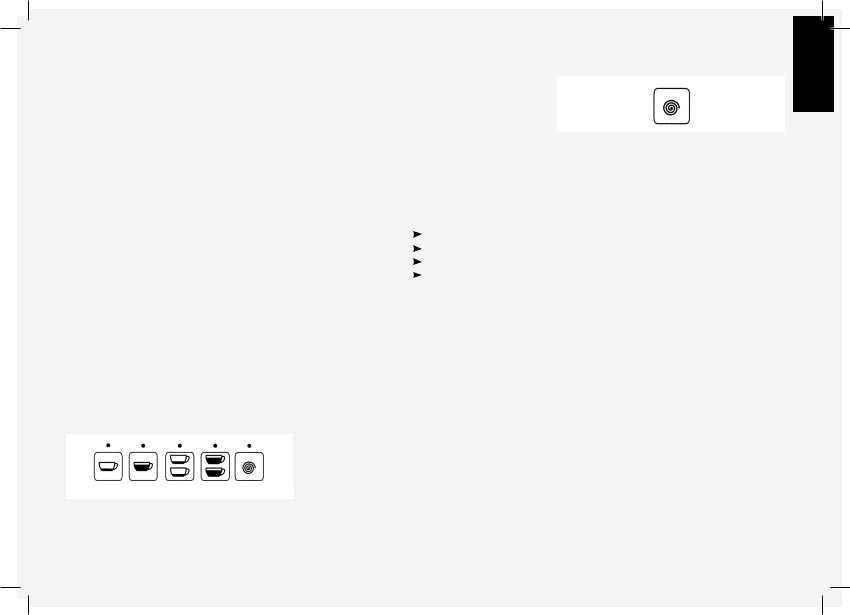
Programming for the 3D/5 version Press and hold the button with the spiral symbol for more than 4 seconds.
EN
You can then follow the same operations as for the standard version, which are described in the following.
The LEDs stay on for 5 seconds after which, if no button has been pressed, they turn off; you must then repeat the above-mentionedproceduretoturnthem on again and to prepare the electronic module for programming;
1.press the first button within 5 seconds and press it again once you have obtained the desired amount of coffee; at this point, the LEDs will turn off and this button will remain programmed as for the dose brewed previously;
2.repeatstepsfortheotherthreebuttons; any time a button has been programmed, by pressing the button with the spiral again, the LED of the programmed button(s) will remain switched off.
3.once you have programmed the first 4 buttons of the first control panel from the left,thedosageprogramssetaccording to the above will be stored in memory and the 5th button (the one with the spiral) will return to its function as a continuous brewing on/off button.
12
EN
N.B.
The programs for the first group from the left will become the default programs for the remaining groups, although you may wish to program these groups differently in which case you need to follow steps 1 to 5 for the remaining control panels. The leftmost control panel must be programmed first; indeed, if you were to program this last, all its settings would be automatically transferred to the other groups.
It is recommended that each group be programmedseparately,fromlefttoright. Each button also works as a switch and, therefore, you may stop coffee brewing at any time, whenever you have obtained thedesiredquantity,bypressingthesame button.
Fault warnings
If the wheel does not send any signals to the electronic module for more than 3-4 seconds, the LED of the button which has been pressed will start flashing. This means that:
A) water is not flowing over the wheel and is therefore not reaching the coffee groups, which may be due to:
1. the ground coffee being too fine meaning that the coffee gets brewed too slowly (drop by drop) and therefore the wheel cannot measure the water 13
flow within the factory-set time of the electronic module.
2. insufficient water flow through the groups (i.e. onto the coffee powder) probably due to a combination of one or more of the following occurrences:
•partial blockage in one of the pipes;
•a malfunctioning motor pump;
•a malfunctioning solenoid valve;
•partial blockage of the diffuser screen. B) there are calcium deposits inside the water flow counter which prevent the wheel from turning properly.
C) the wheel itself and the sensor (top part) of the counter, may be faulty.
Coffee brewing
Take a portafilter and place some ground coffee in the filter itself: 1 dose for the small filter, 2 doses for the larger filter. Press down on the ground coffee with the supplied tamper and engage the filter holder again into the bottom of the group and then press one of the buttons with the symbols for 1 or 2 cups, short or long
You may press the same button again in order to terminate coffee brewing before its programmed stop. If you need an unusual amount of coffee, you may use the button with the spiral symbol and press it again once you have obtained the desired quantity.
Once the coffee has been completely brewed, the pressure in the filter holder isdischargedautomatically,theportafilter may then be removed to repeat the operation as needed.

GENERAL NOTIONS FOR PREPARING
COFFEE
When the machine has reached its operating pressure, 1.2 - 1.5 bar which may be checked by looking at the upper scale in the pressure gauge (part 3 fig. 1, 2 or 3), and its operating temperature at the same time, with the body/group already at infusion temperature, the filter holder and filter must be heated more since they are at the lowest position of the group itself, and they are partially isolated from the same due to the rubber gasket between them. This operation may be carried out by activating the paddle (fig. 2, part 1) or the switches (part 5, fig. 1 or 3) and keeping them in the brewing position for approx. 45 seconds, at which point they must be turned off and you must wait for 2-3 more minutes.
During this time, the pointer of the lower scale of the pressure gauge (part 3, fig. 1 or 3; or fig. 2, part 4) may reach as
high as 11-12 bar; this may occur any time that, while activating the groups, the motor pump forces cold water into the coffee boiler at a pressure of 8-9 bar and, simultaneously, the PID controller regulating the temperature of the boiler itself switches on the heating elements in order to bring the water contained in such boiler up to operating temperature. However, in this case it is necessary to adjusttheexpansionvalve(marked19Ain fig. 4) in such a way that the pressure may never exceed 12 bar.
Thesizeofthecoffeegranulesisextremely important in preparing a good cup of coffee, as is the type of coffee mix used. The ideal grind can be determined by making various coffees using the amount of ground coffee that you would normally use for each cup (we recommend at least 7 g). The best grind is that which allows coffee to flow out from the filter holder spouts neither too slowly nor too quickly.
IMPORTANT
EN
The temperature of the water in the coffee boiler, and therefore of the groups, may eventually be raised or decreased by means of the PID temperature controller (part 22, fig.4) - see next chapter for further details. The final adjustment should be made during tuning-up, once the machine has been permanently installed. The pressure of the water on the coffee during the brewing is very important. For this reason it is important to set the by-pass on the pump at 9 bar.
This value changes if there are variations on the incoming pressure from your local water system. If there are variations, makethenecessarytechnicaladjustments on the system in order to eliminate them.
14
EN
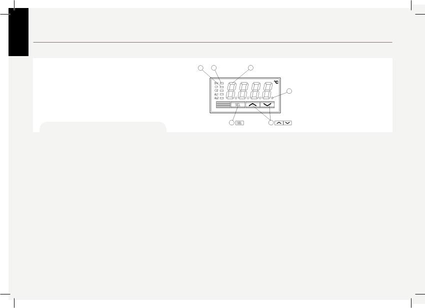
5. PID Temperature controller
Description
Front display description: Coffee boiler element Pilot light 1
N.B.
In 1,2,3 group machines the PID Controller is installed on left side. In 4 group machines on left and right side.
see also fig. 4 - part. 20
1) Coffee boiler element Pilot light
Lights up while controller output 1 stays ON. i.e. heating element is ON
2) Display
Displays the PV (process value) or SV (setting value). When setting a parameter, its name or its value appears.
3) SEL key
Used to switch the PV display to/from the SV display
and select a parameter block and a parameter, and register a set value.
4)  keys
keys
Used to change the SV, call parameters, and change parameter values.
6 SV lamp |
2 Display |
5 Auto-tuning/self-tuning lamp
|
|
*** |
PV: Process Value: measured temp |
3 |
SEL Keys 4 |
Keys |
SV: Setting Value: set temp |
5) Auto-tuning/self-tuning lamp
Flickers under an auto-tuning or self-tuning operation. see detailed info in Manual * (see page 16)
6) SV (setting value) lamp
Displays the PV (process value) in normal conditions (while the lamp is on). Press the SEL key to light
up the SV lamp and display the SV. Note that the lamp stays off while parameters and data are displayed.
It flickers while the display shows the PV (process value) in standby state.
15
EN
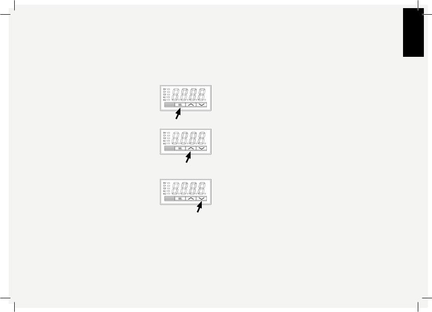
Basic operations
How to set and display the values:
Press the SEL key to display the value
|
* For more detailed information on the potential of this device, |
One press to increase the value by 1. |
consult the: PXR3_Fuji_Micro_controller_Manual.pdf |
|
|
Press and hold this key to increase to |
For further assistance you may contact the After Sales Department: |
desired value then wait a few seconds to |
|
automatically exit programming function. |
enrico@lamarzocco.com |
|
ettore@lamarzocco.com |
One press to decrease the value by 1. |
|
Press and hold this key to decrease to |
|
desired value then wait a few seconds to |
|
automatically exit programming function. |
|
16
EN
6. Dispensing Steam and Hot Water
STEAMING MILK
In order to allow for any condensed water in the wand to be released ALWAYS allow some steam to be discharged by turning on the valve before inserting the steam wand into the pitcher of liquid to be heated. Then insert one of the 2 nozzles (part 9, fig. 1 or 3) which are connected to the steam tap, into the liquid to be heated, turn the knob (part10,fig. 1 or 3) graduallyuntilsteamcomesoutattheendof the nozzle(1).
The steam will transfer heat to the liquid raisingitstemperatureuptoboilingpoint. Be careful not to allow liquid to overflow in order to avoid severe burns.
To prepare milk for making cappuccino withtherightamountoffoam,gothrough the following steps:
▪Place the container half-full of milk under the steam nozzle
▪Open the tap immediately and bring the temperature of the milk to your desired temperature
▪You can then pour this milk into a cup containing warm espresso and you will end up with a fresh cappuccino
In order to prevent part of the liquid to be heated from being sucked back into the boiler (due to a possible temporary decompression inside the boiler tank) which would cause both the steam and the liquid delivered by nozzle part 9 and nozzle part 11 respectively to have a bad odour, we recommend that you devapourize the machine once or twice for just a few seconds, which consists of quickly opening and closing the tap (part 10) with the nozzle (part 9) not immersed in the liquid before starting to steam it. Be careful not to burn yourself with the steam.
Furthermore, once you have immersed the steam wand into the liquid to be steamed in the pitcher, open the steam tapimmediately.Oncetheliquidhasbeen heated, follow this procedure:
▪lower the steam pressure
▪remove the pitcher
▪close the steam tap
DISPENSING HOT WATER
You can obtain hot water by using the fixed nozzle (fig. 1 or 3), located between the group furthest to the right and the steam nozzle (part 9, fig. 1 or 3), and by pressing the button (part 7, fig. 1 or 3) which commands hot water delivery.
17
7. Maintenance and periodic cleaning operationsEN
WARNING
The machine must be installed so that qualified technical personnel can easily access it for maintenance.
CAUTION
The machine must not be dipped in, nor splashed with, water in order to clean it. For cleaning operations, please follow the instructions listed below very carefully.
CAUTION
Never remove the filter holder when water is being delivered. This operation can be extremely dangerous since the high pressure built-up inside the blind filter would spray out hot and slightly caustic water,
which may cause severe burns. The coffee boiler contains water at elevated temperature. Water temperature over 125°F / 52°C can cause severe burns instantly or death from scalding.
Cleaning groups and drain wells
Insert the blind filter into portafilter and put the correct amount of espresso cleaning product (following the product’s instructions) into the filter, engage the portafilter into the group you want to clean.
•Press the brewing button for said group, as if you were making a regular cup of coffee. Stop the water after about 15-20 seconds.
•Start and stop the group several times untilyounoticeclearwaterbeingreleased instead of soapy water when you remove the portafilter.
Do not remove the portafilter when group is actually brewing water.
•Rinse the group using a normal filter in the portafilter, by running hot water through it several times.
Cleaning filters and filter holders
With daily cleaning of the stainless steel filters and portafilters it is sufficient to clean them with water and a cloth or appropriate brush. Otherwise, using an espresso cleaning product, following the product’s instructions put the correct dose in about 1/2 a litre of water inside a heat-resistant container and heat.
•If using stainless steel portafilters with snap-on spouts remove the spout. Immerge filters and metallic parts of portafilters (not handles) in the hot solution and leave them submerged for about 30 minutes.
•Rinse thoroughly with clean water and run hot water through the group several times with the filter and portafilter engaged.
• Make one cup of coffee in order to remove any unpleasant flavour.
Cleaning the drain collector
Remove the drain tray grill every night, pull out the water drain collector and clean it thoroughly. Also inspect and clean the drain well (part 19) at least twice a week, and remove any leftover grounds with a tablespoon.
Cleaning the body
Wipe the stainless steel surfaces with a soft cloth in the direction of the glazing marks, if any. Do not use any alcohol or solvents whatsoever on painted or imprinted parts in order not to damage them.
Cleaning the hot water and steam nozzles
Steam nozzles must be cleaned immediately after use with a damp cloth and by producing a short burst of steam (being careful to avoid burns) so as to prevent the formation of deposits inside the nozzles themselves, which may alter the
flavour of other drinks to be heated.
Cleaning the diffuser screens (infusion
filter)
Due to filter holder discharge operations (subsequent to coffee brewing), a certain amount of coffee grounds may slowly build-up on and obstruct, even partially, the infusion filter. To clean, you must first
18
|
|
|
|
|
|
|
|
|
|
|
|
|
|
|
|
|
|
|
|
|
|
|
|
|
|
|
|
|
|
|
|
|
|
|
|
|
EN |
|
remove it by unscrewing the retainer |
||||||||||||||||||||||||||||||||
|
|
||||||||||||||||||||||||||||||||||
|
|
|
|
screw, then soak in espresso detergent |
|||||||||||||||||||||||||||||||
|
|
|
|
powder. |
|||||||||||||||||||||||||||||||
|
|
|
|
|
|
|
|
|
|
|
|
|
|
|
|
|
|
|
|
|
|
|
|
|
|
|
|
|
|
|
|
|
|
|
|
|
|
|
|
|
|
|
|
|
|
|
|
|
|
|
|
|
|
|
|
|
|
|
|
|
|
|
|
|
|
|
|
|
|
|
|
|
|
|
|
|
|
|
|
|
|
|
|
|
|
|
|
|
|
|
|
|
|
|
|
|
|
|
|
|
|
|
|
|
|
|
|
|
|
|
|
|
|
|
|
|
|
|
|
|
|
|
|
|
|
|
|
|
|
|
|
|
|
|
|
|
|
|
|
|
|
|
|
|
|
|
|
|
|
|
|
|
|
|
|
|
|
|
|
|
|
|
|
|
|
|
|
|
|
|
|
|
|
|
|
|
|
|
|
|
|
|
|
|
|
|
|
|
|
|
|
|
|
|
|
|
|
|
|
|
|
|
|
|
|
|
|
|
|
|
|
|
|
|
|
|
|
|
|
|
|
|
|
|
|
|
|
|
|
|
|
|
|
|
|
|
|
|
|
|
|
|
|
|
|
|
|
|
|
|
|
|
|
|
|
|
|
|
|
|
|
|
|
|
|
|
|
|
|
|
|
|
|
|
|
|
|
|
|
|
|
|
|
|
|
|
|
|
DIFFUSER SCREEN / |
|
SCREW |
||
INFUSION FILTER |
||
|
DIFFUSER - fig. 5 |
Motor Pump
The motor pump is of the positivedisplacement type and can develop a pressure of 14 bar. The operating pressure is 8-9 bar and is factory preset during testing; however, such pressure may vary from place to place since the pump pressure is affected by the incoming water mains pressure. You must always check the pressure itself by looking at the lower scale on the pressure gauge (part 3, fig. 1 or 3; part 4, fig. 2) whenever you are brewing coffee, and you can increase such pressure, as required, by turning the by-pass screw (below the plug located on the side to which the pump power sup-
ply is connected) clockwise, or reduce it by turning the screw counter-clockwise. Adjust pressure only when at least one group is brewing coffee.
IMPORTANT
When you activate the motor pump by pressing the specific button (part 8, fig. 1 or 3) you also give pressure directly to the coffee boiler.
If you activate the motor pump when the machine is cold, a start-up pressure of 8-9 bar will develop; thus, once the heat-
ing elements start working and the water temperature increases, the liquid will expand increasing the start-up pressure by about 3 bar, for a total pressure of 11 bar. Once operating pressure is reached, the expansion (safety) valve (part 19A) should start working by discharging a few drops of water, in order to prevent such pressure from exceeding 12 bar.
If the pressure exceeds 12 bar, you must adjust the valve by unscrewing the cap slightly. If this is not sufficient, remove the valve and clear away any calcium deposits. This remedy is valid also if the valve remains open in the drain position (i.e. the pressure cannot increase to 8 bar approx.).
If the machine has not been used for more than 8 hours or, in any case, after long periods of being idle, in order to use the machine to its full potential it is necessary to perform some cleaning cycles before brewing beverages as follows:
-Groups: with the portafilters engaged inthegroupsbrewwaterthrougheachfor at least two minutes
-Being careful to avoid burns, turn on each steam wand for at least one minute.
-Turn on the hot water valve for the time necessary to allow the following quantities of water to be brewed:
At least 1 liter for a 1/2 group machine At least 2 liters for a 3 group machine At least 3 liters for a 4 group machine
If the machine is not going to be used for long periods of time, it is advisable to follow these safety indications:
-Disconnect the machine from the water mains or interrupt the water connection via a mains tap.
-Disconnectthemachinefromtheelec-
trical mains.
WARNING
IF THE ABOVE-MENTIONED INSTRUCTIONS ARE NOT ADHERED TO THE MANUFACTURER CANNOT BE HELD RESPONSIBLE FOR DAMAGE TO PERSONS OR THINGS.
19
8. De-commissioning and demolitionEN
not provided
not provided
WATER FILTER (not provided)
motor pump
Fig. 3 (see also pag. 7)
Startbysettingthemainswitch(part1)to the "0" position.
Disconnecting from the power outlet
In case the machine is connected through the plug (part 24), make sure that the switch (part 23) is also in the Off position before disconnecting. Disconnect the motor pump (part 15) by pulling out its special plug (part 25).
Disconnecting from the water system
Shut off the water supply by closing the specific tap located upstream of the purifierinlet.Disconnectthewaterpipeatthe purifier (part 17) inlet, which is located just downstream of the special tap (part 18), which has been closed in advance.
Proceed to remove the drain well piping (part 19).
At this point, the machine may be removed from the bar, being very careful not to drop it.
The machine is made out of various materials and therefore, if you do not intend to putitbackinservice,itmustbetakentoa specialdisposalcompanywhichwillselect the materials which can be recycled and discard the others.
Current regulations make it illegal to discard such machine by leaving it on public grounds or on any private property.
Recycling notice:
Warning for the protection of the environment.
Old electrical equipment is made of valuable materials, it is not normal domestic waste! We kindly ask that our clients to contribute to the protection of the environment and natural resources by delivering this equipment to the relevant recycling centers, if they such centers are available in their country.
20

EN
8. Mandatory maintenance and check-up operations
These operations are in addition to the Maintenance and Periodic Cleaning Operations as specified in Chapter 7.
The following maintenance and check-up operations sould be carried out by a qualified technician.
N.B. These periodic maintenance operations are not covered by warranty.
EVERY THREE MONTHS |
If MP Model: |
▪ Replace group gaskets |
▪ Rebuild MP valve |
▪ Replace diffuser screens |
EVERY SIX MONTHS |
▪ Clean auto-fill probe |
|
▪ Check vacuum breaker for proper |
▪Rebuild steam assemblies |
operation |
EVERY YEAR |
▪ Inspect water inlet valve |
|
▪ Inspect drain system for leaks or clogs |
▪ Replace portafilter baskets |
▪ Check flow rate for each group |
▪ Inspect group valve plungers |
▪ Check brew temperature |
▪ Inspect vacuum breaker |
▪ Check that brew pressure is at 9bar |
▪ Inspect steam boiler pressurestat |
▪ Check all switches for proper operation |
▪ Inspect contactor |
▪ Check/note water hardness |
▪ Replace over-pressure valve |
(Water quality must be within the range |
|
of parameters specified in the chapter on |
|
Installation, otherwise warrantyis voided) |
|
If AV Model:
▪Check shot volumes
▪Testflowmeter’sohmvalue(ohmvalueis acceptable if greater than 1.8 K ohm, and less than 2.2 K ohm
21

EN
IT
linea & fb70
Manuale d’uso V1.1 - 11/2014
Capitoli
1. |
Avvertenze Generali e Norme di Sicurezza |
pag. 2 |
2. |
DefinizionedeiModelliTrattati |
pag. 4 |
3. |
Installazione |
pag. 7 |
4. |
MessainFunzioneePreparazionedelCaffè |
pag. 11 |
5. |
RegolatorediTemperaturaPID |
pag. 16 |
6.ErogazionediVaporeeAcquaCalda |
pag. 18 |
|
7. |
ManutenzioneePuliziaPeriodica |
pag. 19 |
8. |
MessaFuoriServizioeDemolizione |
pag. 21 |
9.OperazioniProgrammatediManutenzioneediControllo |
pag. 22 |
|
La Marzocco S.r.l.
Via La Torre 14/H
Località La Torre
50038 Scarperia e San Piero (Firenze) - ITALIA
www.lamarzocco.com
info@lamarzocco.com
T: +39 055 849 191
F: +39 055 849 1990
certificazioni disponibili:
1. Avvertenze Generali e Norme di sicurezza
ATTENZIONE
L’USO DI QUESTA MACCHINA È DI TIPO STRETTAMENTE PROFESSIONALE. LA MACCHINA DEVE ESSERE INSTALLATA IN LUOGHI DOVE L’USO È RISERVATO A PERSONALE PREPARATO. È VIETATO
L’UTILIZZO DA PARTE DI BAMBINI.
1)Il presente libretto d'uso costituisce parte integrante ed essenziale del prodotto e dovrà essere consegnato all'utilizzatore. L'utilizzatore dovrà leggere attentamente le avvertenze contenute nel presente libretto, in quanto forniscono le informazioni riguardanti la sicurezza di installazione, d'uso e manutenzione.
Il presente libretto dovrà essere conservato con cura ed essere disponibile per ogni ulteriore consultazione e per ogni nuovo utilizzatoredelprodotto.
2)Controllare l'integrità del prodotto fin dall'imballaggio assicurandosi che non presenti tracce di urti che potrebbero aver causato danni al contenuto.
3)Controllare l'integrità della macchina
dopo aver |
tolto con |
cura l'imballaggio. |
In caso |
di dubbio |
non procedere |
oltre e contattare immediatamente il concessionario o il venditore che provvederà ad inviare personale specializzato ed autorizzato ad operare sulla macchina.
4) Gli elementi dell'imballaggio (scatole, sacchetti, polistirolo espanso e quant'altro)
non devono essere lasciati alla portata dei bambini, in quanto fonti di pericolo, né devono essere dispersi nell'ambiente.
5) Controllare che i dati della targhetta siano rispondenti a quelli della rete elettrica installata nel locale dove sarà utilizzata la macchina.
L'installazione deve essere effettuata in osservanza delle norme vigenti, secondo le istruzioni del costruttore e deve essere eseguita da personale qualificato ed autorizzato. Questa macchina non deve essere installata in una cucina.
Un'installazione non corretta può essere causa di danni a persone, animali o cose, per i quali il costruttore non può essere considerato responsabile.
La sicurezza del funzionamento elettrico di questo apparecchio è ottenuta soltanto quando il collegamento alla rete elettrica è effettuato correttamente in rispondenza delle vigenti norme di sicurezza ed in particolare con attenzione all'efficienza dell'impianto di messa a terra. È necessario verificare quest'ultima in quanto fondamentale requisito di sicurezza e, in caso di dubbio, richiedere un controllo accuratodapartedipersonalequalificato.
Inoltre dovrà essere controllato che la portata dell'impianto elettrico sia idonea alla potenza massima assorbita riportata sulla targa ed in particolare dovrà essere posta attenzione che la sezione dei cavi sia
idonea.
È sconsigliabile l'uso di adattatori, prese multiple e/o prolunghe. Qualora non sia possibilefarneamenoènecessarioutilizzare solamente spine, adattatori e prolungheIT conformi alle vigenti norme di sicurezza, facendo attenzione a non superare il limite
diportataepotenzariportatosull'adattatore e sulle prolunghe.
6)Questo apparecchio dovrà essere utilizzato solo per l'uso per il quale è stato espressamente progettato e realizzato. Ogni altrousoèdaconsiderarsiimproprioequindi pericoloso. Il costruttore non può essere considerato responsabile per eventuali dannicausatidausierroneiedirragionevoli.
Questo apparecchio deve essere installato in modo conforme alle norme applicabili agli impiantiidraulici.
7)L'usodiunqualsiasi apparecchioelettrico comporta l'osservanza di alcune regole di
comportamento fondamentali.
Inparticolare:
• non toccare l'apparecchio con mani o piedibagnatiodumidi;
• nonusarel'apparecchioapiedinudi;
• non usare prolunghe in locali adibiti a bagnoodoccia;
• non tirare il cavo di alimentazione per scollegare l'apparecchio dalla rete elettrica;
• non lasciare l'apparecchio esposto ad
2
IT
agentiatmosferici(pioggia,soleetc...);
•non permettere che l'apparecchio sia usato da bambini o da persone non in gradodiusarlo;
•non pulire il pannello comandi con panni bagnatiinquantononèatenutastagna.
8) Prima di eseguire qualsiasi operazione di manutenzione e/o di pulizia, porre in posizione di “0” l'interruttore generale situato sulla macchina e disinserire l'apparecchio dalla rete di alimentazione elettrica staccando la spina o spegnendo l'interruttoredell'impianto.Perleoperazioni di pulizia attenersi esclusivamente a quanto
previstonelpresentelibretto.
9)In caso di malfunzionamenti o guasti dell'apparecchio procedere a disinserirlo dalla rete elettrica (come descritto al punto precedente) ed a chiudere il rubinetto di alimentazione dell'acqua. Astenersi da qualsiasi tentativo di riparazione e rivolgersi a personale professionalmente qualificato ed autorizzato. L'eventuale riparazione del prodotto dovrà essere effettuata solamente dalla casa costruttrice o da un centro autorizzato utilizzando esclusivamente ricambi originali. Il mancato rispetto di quanto sopra può compromettere la sicurezza dell'apparecchio e ne fa comunque decadere la garanzia.
10)All'atto dell'installazione occorre prevedere un interruttore omnipolare come previsto dalle norme di sicurezza vigente, munito di fusibili adatti a sopportare la
potenzadellamacchinadaconnettere.
11)Per evitare surriscaldamenti pericolosi, si raccomanda di distendere tutto il cavo di alimentazione.
12)Non ostruire le griglie di aspirazione o di dissipazione ed in particolare non coprire
con panni od altro il piano scaldatazze.
13) Il cavo di alimentazione di questo apparecchio non deve essere sostituito dall'utente, come specificato anche nella targhetta posta in vicinanza dell'uscita dello stesso dalla carrozzeria. In caso di danneggiamento del cavo spegnere l'apparecchio (come descritto al precedente punto 8) e chiudere l'alimentazione dell'acqua e, per la sua sostituzione, rivolgersi esclusivamente a personale professionalmentequalificato.
ATTENZIONE
COME GIÀ RIPORTATO NELLE NOTE PRECEDENTI
IL COSTRUTTORE NON PUÒ ESSERE
CONSIDERATO RESPONSABILE PER DANNI A COSE, ANIMALI E/O PERSONE QUANDO IL
PRODOTTO NON È STATO INSTALLATO SECONDO LE PRESCRIZIONI CONTENUTE NEL PRESENTE MANUALE E/O QUANDO NON È UTILIZZATO PER FUNZIONI QUALI L'EROGAZIONE DI CAFFÈ E DI BEVANDE CALDE.
ATTENZIONE
QUESTA MACCHINA NON È ADATTA ALL'USO ALL’ ESTERNO. NON USARE GETTI D'ACQUA PER PULIRE LA MACCHINA, NON POSIZIONARE LA MACCHINA DOVE VENGONO USATI GETTI D'ACQUA.
Tutto quanto evidenziato in questo manuale è valido anche per la serie denominata“FB/70”.Leunichedifferenze riguardano le dimensioni esterne dell'apparecchio.
MISURE E PESI COMUNI ALLA
SERIE LINEA
LINEA |
1 gr |
2gr |
3gr |
4gr |
A cm/pollici |
45.5/18 |
45.5/18 |
45.5/18 |
45.5/18 |
B cm/pollici |
56/22 |
56/22 |
56/22 |
56/22 |
C cm/pollici |
49/20 |
69/28 |
93/37 |
117/46 |
PESO kg/lb |
44/97 |
58/128 |
74/163 |
92/203 |
MISURE E PESI COMUNI ALLA SERIE FB/70
FB/70 |
2gr |
3gr |
4gr |
A cm/pollici |
45.5/18,5 |
45.5/18,5 |
45.5/18,5 |
B cm/pollici |
64/25,5 |
64/25,5 |
64/25,5 |
C cm/pollici |
84/33 |
108/42,5 |
135/52,25 |
PESO kg/lb |
58/128 |
74/163 |
92/203 |
3
2. Definizione dei modelli trattati
Il presente manuale d'uso si riferisce esclusivamente ai seguenti modelli di nostra costruzione:
Mod. EE, Mod. AV e Mod. PADDLE ad 1, 2, 3 e 4 erogatori
IT
2 |
1 |
2 |
5 |
Legenda |
3 |
4 |
|
|
1Interruttore generale
2Oblò del livello acqua
3Manometro
4Gruppi erogazione caffè
5Interruttore erogazione caffè
6Interruttore scaldatazze (macchine non-UL)
7 |
Interruttore erogazione acqua calda |
8 |
Interruttore riempimento manuale |
9 |
Lancia per vapore |
10 |
Manopola per erogazione vapore |
11 |
Lancia acqua calda |
1 |
Leva gruppo |
2 |
Manopola per erogazione vapore |
3 |
Manometro caldaia vapore |
4 |
Manometro caldaia caffè |
5 |
Interruttore riempimento manuale |
fig. 1 - Modello EE a 1, 2, 3, e 4 gruppi erogatori fig. 2 - Pannello frontale del modello
PADDLE con 1, 2, 3 e 4 gruppi erogatori
4
IT
Descrizione generale
Le macchine modello EE e PADDLE sono disponibili nelle versioni con 1, 2, 3 e 4 gruppi erogatori e sono essenzialmente costituitedalleseguentiparti:
1.Caldaia servizi (generatore di vapore ed acquacalda);
2.Caldaiasaturapererogazionecaffè;
3.Gruppierogatori;
4.Involucro;
5.Elettropompa;
Descrizionedellevarieparti
1. Caldaia vapore
È costituita da un involucro cilindrico di lunghezza variabile a seconda del numero dei gruppi erogatori del caffè ed è realizzata in acciaio inox, collaudata in prova idraulica esemplare per esemplare ad una pressione di 3 bar e idonea alla pressione di esercizio di 1,5 bar. A seconda del numero di erogatori sihannoiseguentivolumieffettiviepotenze
installate:
1gruppo |
litri3,5 |
1300Watt |
2gruppi |
litri7 |
2000Watt |
3gruppi |
litri11 |
3000Watt |
4gruppi |
litri14,5 |
3800Watt |
In certi paesi è possibile reperire resistenze di maggiore potenza per la caldaie vapore. Alle estremità dell'involucro cilindrico sono applicatiicoperchiesuunoèricavatolasede per le resistenze elettriche di riscaldamento e vaporizzazione dell'acqua che permettono il raggiungimento della pressione d'esercizio
5
in circa 25'. Il mantenimento della pressione di esercizio è realizzato da un pressostato. Sulla caldaia sono applicati vari raccordi per gli accessori di sicurezza, per i servizi di
acqua calda e vapore e per l'alimentazione.
2.Caldaiacaffè
Ciascunaunitàècollaudatainprovaidraulica esemplare per esemplare ad una pressione di 16 bar e idonea alla pressione di esercizio di 9 bar. A seconda del numero di erogatori sihannoiseguentivolumieffettiviepotenze
installate:
1gruppo litri1,8 |
|
1000 |
Watt |
|
2gruppi |
litri3,4 |
|
1400 |
Watt |
3gruppi |
litri5,0 |
|
1600o1900Watt |
|
4gruppi |
litri3,4 |
+3,4 |
1400 |
+1400Watt |
(2 caldaie installate)
È costituita da un involucro cilindrico di lunghezza variabile a seconda del numero dei gruppi erogatori del caffè ed è realizzata in acciaio inox.
Alle estremità dell'involucro cilindrico sono applicati i coperchi e su uno è ricavato la sede per le resistenze elettriche di riscaldamento dell'acqua che tramite un termostato di precisione con dT di ±0,5°C mantengono costante la temperatura dell'acqua, temperatura che può essere adeguata a quella ottimale per differenti misceledicaffè.Sullacaldaiasonoapplicatii gruppi erogatori.
3. Gruppi erogatori
Sono costituiti da un blocco di acciaio inox
sul quale si innesta il portafiltro nella quale si mette la dose di caffè in polvere e dal quale tramite il beccuccio l'espresso scende nellasottostantetazza/edopoilcomandodi erogazione.
4. Involucro
Ècostituitodaunascoccainlamieradiacciaio verniciata e in acciaio inox. La struttura è frutto di particolari studi per la funzione estetica, per ottimizzare l'ergonomia per l'utilizzatoreeridurrealminimolapossibilità di danni.
5.Elettropompa
La pompa rotativa, installata sulla tubazione di alimentazione dell'acqua, è predisposta per entrare in funzione ad ogni azionamento dei gruppi erogatori di caffè e tramite un autolivello per reintegrare l'eventuale consumo di acqua della caldaia servizi.
ATTENZIONE
Le caldaie del caffè e del vapore contengono acqua a temperatura elevata. Una temperatura dell'acqua superiore a 52°C può essere causa di gravi ustioni o di morte (caldaia caffè 93,3°C - caldaia vapore 127°C)
ATTENZIONE
La presente apparecchiatura deve essere tenuta a distanza da bambini e/o dei portatori di handicap fisici o mentali o da coloro che non sono in possesso delle conoscenze necessarie a garantirne il corretto utilizzo a meno che questi ultimi non operino sotto il diretto controllo di personale qualificato.
Descrizione generale
La macchina modello AV viene costruita nelle versioni con 1, 2, 3 e 4 erogatori ed
è essenzialmente costituita come il modello EE.
Questo modello differisce dal modello EE in quanto consente all'operatore di predisporre a suo piacimento quattro diverse quantità di acqua in erogazione di caffè. Per ciascuno gruppo erogatore è quindi prevista una pulsantiera a 5 tasti, atti a selezionare su richiesta della clientela:
-1 dose di acqua per un caffè espresso;
-1 dose di acqua per un caffè lungo;
-1 dose di acqua per due caffè normali;
-1 dose di acqua per due caffè lunghi;
Il quinto pulsante è utilizzato come programmatore degli altri, come vedremo in seguito, e come interruttore off-on per erogazione continua a piacimento.
Fig. 3 - Modello AV ad 1, 2, 3 e 4 erogatori
Legenda
1Interruttore generale
2Oblò del livello acqua
3Manometro
4Gruppi erogazione caffè
5Pulsantiera erogazione caffè (modello AV)
6Interruttore scaldatazze (macchine non-UL)
7Interruttore erogazione acqua calda
8Interruttore riempimento manuale
9Lancia per vapore
10Manopola per erogazione vapore
11Lancia acqua calda
12Interruttore erogazione manuale
Pulsantiera erogazione caffè del modello AV
IT
6
IT
3. Installazione
|
Legenda |
|
|
|
|
|
|
|
Cavoda380/220/200Volt |
|
|
|
|
Cavo da 220/200 Volt |
|
|
|
|
Tubo acqua |
|
|
|
|
Tubo di scarico |
|
1 |
Interruttore generale |
19A |
Valvola di espansione |
|
13 |
Tubi di scarico |
20 |
Copertura gruppo |
|
14 |
Terminale |
21 |
Vite di sfiato |
|
15 |
Elettropompa |
22 |
Regolatore di temperatura PID |
|
16 |
Uscita filtro |
23 |
Interruttore (non fornito) |
|
17 |
Ingresso filtro |
24 |
Spina (non fornita) |
|
18 |
Rubinetto |
25 |
Connettori |
non fornito |
19 |
Pozzetti di scarico |
|
|
|
|
ATTENZIONE |
||
non fornita |
LA MACCHINA DEVE ESSERE POSTA IN |
|||
POSIZIONE ORIZZONTALE SU UN BANCONE AD ALMENO |
||||
|
|
80CM DA TERRA. |
||
|
|
FILTRO ACQUA |
|
ATTENZIONE |
|||
|
|
(non fornito) |
|
||||
|
|
|
|
|
|
|
LA MACCHINA È PREDISPOSTA PER ESSERE COLLEGATA IN |
|
|
|
|
|
|
|
MODO PERMANENTE AD UN IMPIANTO ELETTRICO FISSO. |
elettro- |
|
|
|
|
SI RACCOMANDA L'INSTALLAZIONE DI UN INTERRUTTORE |
||
|
|
|
|
DIFFERENZIALE CON UNA CORRENTE OPERATIVA RESIDUA |
|||
pompa |
|
|
|
|
|||
|
|
|
|
NOMINALE NON SUPERIORE A 30MA. |
|||
|
|
|
|
|
|
|
|
Fig. 4
7
 Loading...