


manual
kb90
The kb90 is tailored to suit the needs of the world’s busiest coffee bar, making espresso preparation easier for baristas. La Marzocco, considering the needs of high volume cafes and their staff, has redesigned the portafilter system to reduce the wrist strain of the user. By focusing on simplifying the fine motions, the machine is able to shave seconds off of the time required to make each drink. The kb90 sets a new standard in high volume cafe performance for La Marzocco.
kb90
Operating Manual V1.0 - 09/2018
MAN.22.1
Chapters
1. |
General Warnings and Safety Specifications |
page 3 |
2. |
Definition of Available Models |
page 7 |
3. |
Installation |
page 10 |
4. |
Machine Operation and Coffee Preparation |
page 16 |
5. |
Dispensing Steam and Hot Water |
page 19 |
6. |
Maintenance and Periodic Cleaning Operations |
page 20 |
7. |
De-commissioning and Demolition |
page 23 |
8. |
Mandatory Maintenance and Check-up Operations |
page 24 |
9. |
Precision Scale |
page 25 |
10. Straight-in |
page 27 |
|
11. Software Programming Guide |
page 28 |
|
certifications available:
La Marzocco S.r.l.
Via La Torre 14/H
Località La Torre
50038 Scarperia e San Piero
(Firenze) - ITALIA
www.lamarzocco.com
info@lamarzocco.com
T: +39 055 849 191 F: +39 055 849 1990
EN
1. General Warnings and Safety Specifications
WARNING |
|
|
|
CAUTION |
|
|
years of age) with reduced |
|
|||||||||||||
This machine is for professional |
|
As already mentioned in |
|
physical, sensory or mental |
|
||||||||||||||||
use only and should be installed |
|
the preceding notes, the |
|
capabilities, |
|
or |
lack |
of |
|
||||||||||||
in locations where its use and |
|
manufacturer shall not be held |
experience and knowledge, |
|
|||||||||||||||||
|
as |
long |
as |
they have |
|
||||||||||||||||
maintenance is restriced to |
|
responsible for damage to |
|
|
|||||||||||||||||
|
|
been given |
supervision or |
|
|||||||||||||||||
trained personnel. Children are |
|
objects, animals and/or people |
|
||||||||||||||||||
|
instructions |
|
concerning |
|
|||||||||||||||||
forbidden to operate or play with |
|
whenever the machine has not |
|
|
|||||||||||||||||
|
the use of the appliance |
|
|||||||||||||||||||
the machine. |
been installed according to the |
|
|||||||||||||||||||
by |
a |
person |
responsible |
|
|||||||||||||||||
|
|
instructions contained in this |
for their safety and if they |
|
|||||||||||||||||
WARNING |
|
manual, and is not used to do |
understand dangers. |
|
|
|
|
|
|
|
|||||||||||
The Coffee machine must be |
|
what it was designed for (i.e. |
• Children |
|
should |
be |
|
||||||||||||||
placed in a horizontal position on |
preparing coffee and hot drinks). |
supervised |
to |
ensure |
that |
|
|||||||||||||||
a counter higher than 80 cm from |
1) Important safeguards |
|
|
they do not play with the |
|
||||||||||||||||
the ground. |
• |
The |
weighted |
sound |
appliance. |
|
|
|
|
|
|
|
|
|
|
|
|||||
|
• Keep the appliance and |
|
|||||||||||||||||||
|
|
pressure |
level |
of |
the |
|
|||||||||||||||
|
|
machine |
is |
lower than |
its cord out of the reach of |
|
|||||||||||||||
WARNING |
|
children less than 8 years |
|
||||||||||||||||||
|
70dBA. |
|
|
|
|
|
|||||||||||||||
This machine is not suitable |
• |
Use, |
|
cleaning |
|
and |
of age. |
|
|
|
|
|
|
|
|
|
|
|
|
||
for outdoor use. Jets of water |
|
|
|
|
|
|
|
|
|
|
|
|
|
|
|
|
|||||
|
maintenance of this coffee |
2) |
This |
operating |
manual |
|
|
|
|
|
|
||||||||||
should not be used to clean the |
|
|
|
|
|
|
|
||||||||||||||
|
machine |
are |
realized |
|
|
|
|
|
|
||||||||||||
machine, nor should it be placed |
|
is an integral and essential |
|
|
|
|
|
|
|||||||||||||
|
by |
people |
(including |
|
|
|
|
|
|
||||||||||||
where water jets are used. |
|
children |
more |
than |
8 |
part |
of |
the |
|
product |
and |
|
|
|
|
|
|
||||
|
|
|
|
|
|
|
|
|
|
|
|
|
|
|
3EN |
|
|
||||
|
|
|
|
|
|
|
|
|
|
|
|
|
|
|
|
|
|
|
|
|
|
|
|
|
|
|
|
|
|
|
|
|
|
|
|
|
|
|
|
|
|
|
|
|
|
|
|
|
|
|
|
|
|
|
|
|
|
|
|
|
|
|
|
|
|
|
|
|
|
|
|
|
|
|
|
|
|
|
|
|
|
|
|
|
|
|
|
|
|
|
|
|
|
|
|
|
|
|
|
|
|
|
|
|
|
|
|
|
|
|
|
|
|
|
|
|
|
|
|
|
|
|
|
|
|
|
|
|
|
|
|

EN
must be supplied to users. Users are asked to read the enclosed warnings and cautions carefully, as they provide valuable information concerning safety during installation, operation and maintenance. This manual must be kept in a safe place and be available for consultation to new and experienced users alike.
3)Ensure product’s integrity by inspecting the packaging, making sure it presents no signs of damage which might have affected the enclosed machine.
4)Check the machine’s integrity after having carefully removed the packaging.
Note: In case of doubt, do not go
4
on any further and contact your |
codes. |
|
The |
installation |
|||
dealer or retailer immediately. They |
also must comply to the |
||||||
will send out specialized personnel |
manufacturer’s |
instructions, |
|||||
authorized to perform service on |
and must be performed by |
||||||
the espresso machine. |
qualified |
|
and |
authorized |
|||
5) Packaging (boxes, plastic |
personnel. |
|
|
|
|
||
bags, foam parts and whatever |
8) |
Incorrect |
installation |
may |
|||
else) must not be left around |
cause |
for |
injury/damages to |
||||
within easy reach of children, |
people, animals or objects, for |
||||||
due to the potential danger it |
which the manufacturer shall |
||||||
represents, nor be discarded |
not be held responsible. |
|
|||||
in the environment. |
9) Safe electrical operation of |
||||||
|
|||||||
6) Check to see that data on |
this device will be achieved |
||||||
the rating plate corresponds |
only when the connection to |
||||||
to those of the main electrical |
the power outlet has been |
||||||
supply which the machine will |
completed |
|
correctly |
and |
|||
be hooked up to. |
in observance of all local, |
||||||
7) The equipment must be |
national, |
and |
international |
||||
electrical |
codes |
and safety |
|||||
installed to comply with the |
regulations, |
and |
particularly |
||||
applicable federal, state or |
by |
grounding |
the |
unit. |
|||
local electrical and plumbing |
Make |
sure |
grounding |
has |
|||

been done properly as it represents a fundamental safety requirement. Ensure qualified personnel check such connection.
10)Furthermore, you must ensure that the capacity of the available electrical system is suitable for the maximum power consumption indicated on the espresso machine.
11)We do not recommend using adapters, multiple plugs and/or extension cords. If you cannot avoid using them, make sure that they are exclusively of the kind which conforms to local, national, and international electrical codes and safety regulations, being careful not to exceed the power and current ratings
indicated on such adapters and extension cords.
12)This device must be used exclusively for the functions it has been designed and built for. Any other application is inappropriate and dangerous.
The manufacturer shall not be held responsibleforanydamagescaused by improper and/or irrational use.
This machine should not be installed in kitchens.
13)Using any electrical device requires that certain fundamental rules be observed. In particular:
• do not touch the device with wet or humid hands and feet;
• do not use the device while having no shoes on your feet;
•do not use extension cords in bath or shower rooms;
•do not unplug the device from the power outlet by pulling on the power supply cable;
•do not expose the device to atmospheric agents (rain, sun, etc.);
•do not allow children or untrained people to use this device;
•do not clean the control panel with a wet cloth since it is not watertight.
14) Before carrying out any maintenance and/or cleaning operations, turn the main switch, which is located on the front left of the machine, to the “0” or “OFF” position, and disconnect the machine
from the electrical networkEN
5
EN
by unplugging the cord or by switching off the relative circuit breaker. For any cleaning operation, follow exclusively the instructions contained in this manual.
15) In case the machine is operating in a faulty manner or breaks down, disconnect it from the electrical network (as described in the preceding point) and close the water supply valve. Do not attempt to repair it. Contact a qualified and authorized professional to performanyrepair. Anyrepairs must be performed exclusively by the manufacturer or by an authorized centre using only original parts. Non compliance with the above could compromise the safe operation of the machine.
6
16)You should plan to make use of an omnipolar connector during installation, as required by local, national, and international electrical codes and regulations.
17)In order to avoid dangerous overheating problems, it is recommended that the power supply cable be fully unfurled.
18)Do not obstruct air intake and exhaust grilles and, in particular, do not cover the cup warmer tray with cloths or other items.
19)The machine’s power supply cable must not be replaced by users. In case the power supply cable becomes damaged, shut off the machine and disconnect the
machine from the electctrical network by switching off the relative circuit breaker and close off the water supply; to replace the power supply cord, contact qualified professionals exclusively.
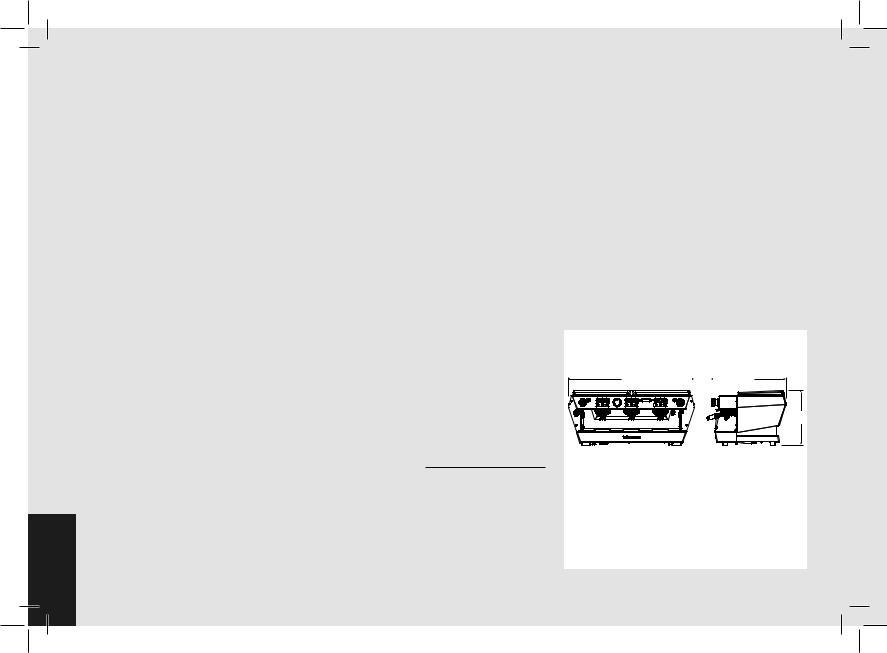
20) Common Dimensions, Weights,
and Features
AA |
|
|
|
|
|
B |
|
|
|
||||
|
|
|||||
|
|
|
|
|
|
|
|
|
|
|
|
|
|
C
kb90 |
2 groups |
3 groups |
|
|
|
A [mm] |
810 |
1050 |
|
|
|
B [mm] |
620 |
620 |
|
|
|
C [mm] |
448 |
448 |
|
|
|
WEIGHT [kg] |
77 |
101 |
|
|
|
2. Definition of Available Models
This operating manual refers exclusively to the following models, of our own manufacture: kb90 model 2 and 3 groups
8 |
12 |
5 |
3 |
|
3 |
6 |
3 |
11 |
8 |
4 |
|
|
|
|
|
|
|
|
|
1 |
|
|
|
|
|
|
|
|
13 |
|
|
|
|
|
|
|
|
|
9 |
7 |
|
|
|
|
|
|
|
|
7 |
10 |
|
|
|
|
|
|
|
|
|
|
14 |
15 |
2 |
15 |
14 |
|
15 |
|
|
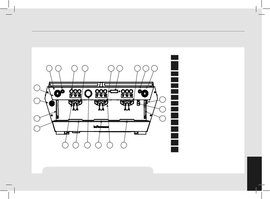
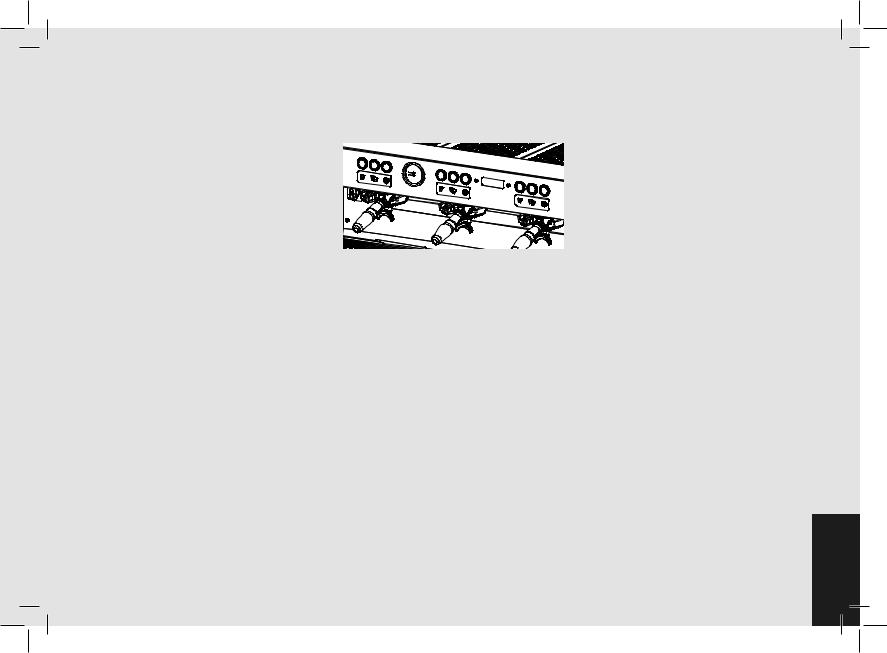
Fig. 1 - Model with 2 or 3 groups
Legend
1Main Switch
2Pressure Gauge (Steam & Brew water)
3Brew Groups
4Control Panel
5Group #1 Keypad
6Digital Display
7Steam Wand
8Steam Knob
9 Hot Water dispense nozzle
10Removable Drain Tray
11Hot Water Button
12Cup Warmer Button
13Hot Water Mix Valve
14Straight-in
15Precision Scale
For additional information on electronics, keypads, and software programming, please see the section entitled Software Programming
your Espresso Machine. EN
7

1) General Description
The machine is built in 2 and 3 coffee group versions and is essentially composed of the following parts:
•Steam Boiler (produces steam and hot water);
•Coffee (“saturated”) boiler;
•Brewing groups;
•Exterior Cover;
•Water pump.
2) Description of the various parts
• Steam Boiler
The Steam Boiler consists of a cylindrical tank, of varying length according to the number of coffee groups, which is made of AISI 300 series stainless steel. Each unit is subjected to a hydraulic test, at a pressure of 6 bar, and has an operating pressure of 1.3-1.5 bar. The following is a list of effective volumes and power ratings according to the number of groups installed:
|
|
|
|
|
|
2 groups |
7,0 liters |
3000 Watts |
|
|
|
|
|
|
3 groups |
11 liters |
4000 Watts |
|
|
|
|
|
|
Covers are welded at either end of the |
||
|
|
|
|
|
|
cylindrical tank and on one of them there |
||
|
|
|
|
|
|
is a housing for the water heating element, |
||
|
|
|
|
EN |
which allows the steam boiler to reach |
|||
|
|
|
|
operatingpressurewithinapproximately25 |
||||
|
|
|
|
8 |
|
|
||
|
|
|
|
|
|
|
|
|
|
|
|
|
|
|
|
|
|
|
|
|
|
|
|
|
|
|
|
|
|
|
|
|
|
|
|
|
|
|
|
|
|
|
|
|
|
|
|
|
|
|
|
|
|
minutes. Operating pressure is maintained by temperature probe and PID controller. The steam boiler has various fittings used for safety devices, for supplying hot water and steam, and for the heating element.
Composed of AISI 300 series stainless steel tube. Heating is accomplished through an immersion-type plated heating element.
•Operating pressure of 1.3-1.5 bar, controlled automatically through a pressure switch or a temperature probe, adjusted to open the heating element supply circuit at 1.5 bar and close it at 1.3 bar.
•The pressure is displayed by means of a pressure gauge with a scale of 0 to 2 bar.
•Safety device, based on an expansion type mechanical valve, with counteracting spring adjusted to 1.8 bar.
•Testing: hydraulic test at 4.5 bar performed on ready-to-use small boilers, at our factory.
•Coffee Boiler
The Coffee Boiler consists of a cylindrical tank made of AISI 300 series stainless steel. One each group (hot water generator for brewing coffee).
Each unit is subject to a hydraulic test, at a pressure of 18 bar, and has an
operating pressure of 9 bar. The following is a list of effective volume and power ratings according to the number of groups installed:
2 groups |
2 x 1,3 liters |
2 x 800 Watts |
3 groups |
3 x 1,3 liters |
3 x 800 Watts |
Covers are installed at either end of the cylindrical tank and on one of them there is housing for the water heating elements. The temperature of the coffee boiler is maintained by an electronic temperature controller (PID capable) with an accuracy of 0.2°C. The brewing groups are installed on the boiler.
Composed of an AISI 300 series stainless steel tube. Heating is accomplished through an immersion-type plated heating element.
•Operating temperature 95°C (adjustable), controlled automatically by an electronic temperature controller with an accuracy of 0.2 °C. Operating pressure of 9 bar.
•Pressure is displayed through a pressure gauge with a scale from 0 to 18 bar.
•Safety device, based on an expansion type mechanical valve, with ounteracting spring adjusted to 13 bar.
•Testing: Hydraulic test at 18 bar performed on ready-to-use small boilers, at our factory.
• Brewing groups
They consist of a precision casting made of stainless steel. The brewing group accepts the portafilter used to hold the ground coffee; the espresso flows through the brewing group, through the portafilter basket, through the portafilter spout, and into the cup(s) after the brewing button has been pressed.
• Exterior cover
The exterior consists of painted and stainless sheet steel panels. To provide good aesthetics, to optimize ergonometrics for the operator and to reduce the chance of damage to a minimum.
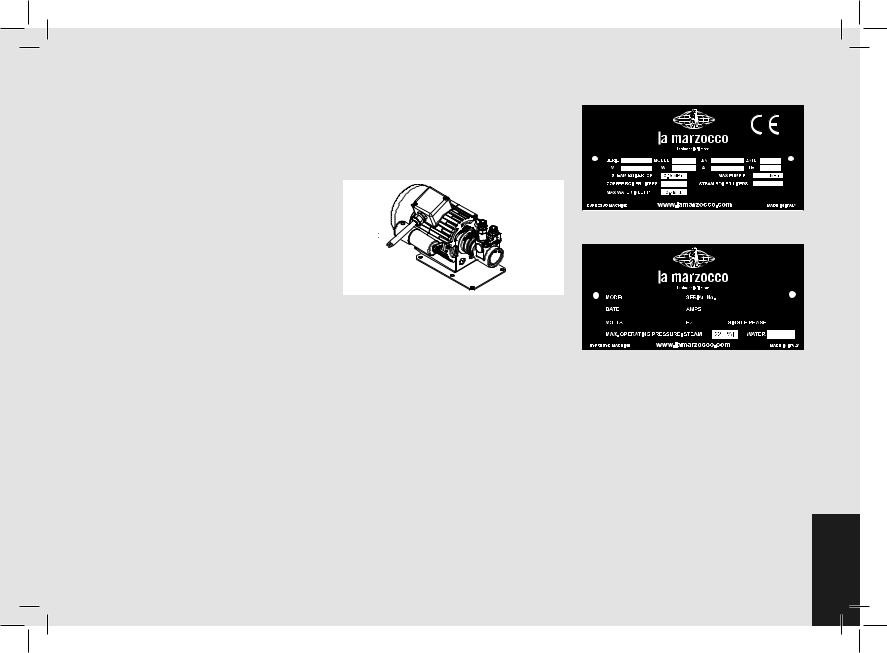
• Water pump
The rotary vane pump, is installed on the water supply tubing and is set up to operate anytime the coffee groups are activated, and through an autofill system whenever the water boiler needs to be replenished.
• Machine CE plate:
KB90 |
3AV |
KB000000 |
01/18 |
220-240 |
7783 |
33.8 |
50/60 |
|
|
|
0.9 |
|
1.3x3 |
|
11.8 |
• Machine ETL plate:
KB90 3AV |
|
|
|
KB000000 |
|
|
|
|
|
|
|
01/18 |
|
29-33 |
|
||
|
|
|
|
|
|
|
|
|
|
|
|
161 

9EN
EN
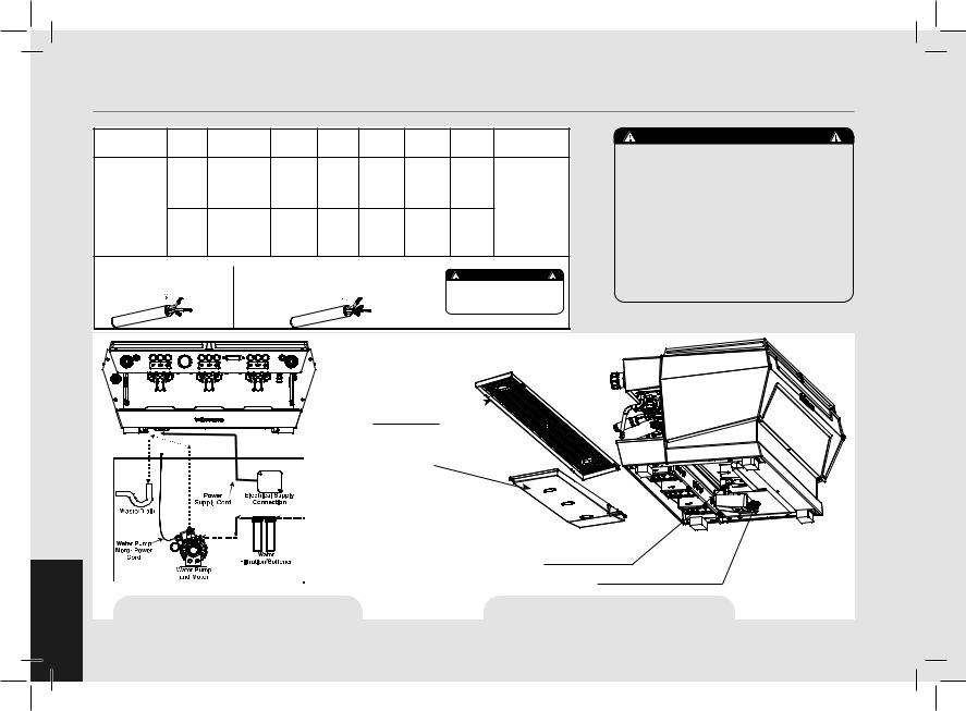
3. Installation
|
|
|
RATED |
RATED |
COFFEE |
STEAM |
TOTAL |
POWER CORD |
|
MODEL/SERIES GROUP |
V/Hz |
POWER |
INPUT |
BOILER |
BOILER |
SIZE (mm²) |
|||
|
|||||||||
|
|
|
(W) |
(A) |
WATTAGE |
WATTAGE |
WATTAGE |
|
|
|
|
AC220-240V/60Hz |
5666 |
24.6 |
1600 |
3000 |
5666 |
SEE ELECTRICAL |
|
|
2GR |
AC208-240/60H |
5360 |
21-24 |
1600 |
3000 |
5360 |
||
|
|
||||||||
KB90 |
|
|
|
|
|
|
|
CONNECTIONS |
|
|
|
AC220-240V/60Hz |
7783 |
33.8 |
2400 |
4000 |
7783 |
FOR DETAILS |
|
|
|
|
|||||||
|
3GR |
AC208-240/60Hz |
7324 |
29-33 |
2400 |
4000 |
7324 |
|
|
3 X WIRES 1 X BLUE (NEUTRAL) |
POWER CORD: |
|
|
|
|
|
|||
5 X WIRES 1 X BROWN (PHASE) 1 X BLUE (NEUTRAL) |
|
WARNING |
|||||||
220V |
1 X BROWN (PHASE) |
380V |
1 X GRAY (PHASE) 1 X YELLOW & GREEN (GROUND) |
||||||
|
|
|
|
||||||
|
1 X YELLOW & GREEN (GROUND) |
1 X BLACK (PHASE) |
|
|
THE DETAILS ON THE LEFT DESCRIBE |
||||
|
|
|
|
|
|
|
HOW TO CONNECT EACH WIRE TO THE PLUG. |
||
|
|
|
|
|
|
|
RESPECT ALSO THE LOCAL SAFETY |
||
|
|
|
|
|
|
|
REGULATIONS. |
||
WARNING
The machine is intended to be permanently connected to fixed wiring, and it is mandatory that a residual current device (RCD) with a rated residual operating current not exceeding 30mA is
installed.
DRAIN GRATE 
DRAIN TRAY
|
EXPANSION VALVE |
|
DRAIN HOSE CONNECTION |
Fig. 2 - Installation Guide |
Fig. 3 - Installation Nomenclature |
10
WARNING
At each installation, the machine should be equipped with a new set of tubes for plumbing and related gaskets.
WARNING
Water pressure supply must be between 0,2 and 0,6 MPa if sufficient pressure is not available we suggest that an additional water supply system is used.
WARNING
Before making any electrical connections make sure that the two strain relief connectors are firmly secured to the body of the machine in order to prevent inadvertent stress on the power
cables.
WARNING
This machine should not be installed in kitchens.
WARNING
Hazardous voltage disconnect from power supply before servicing.
WARNING
The motor pump must be situated close to the machine in an accessible place for maintenance but not for accidental interference and where there is an optimal air circulation.
WARNING
The manufacturer declines any responsibility for any event leading to liability suits whenever grounding has not been completed according to current local, national, and international regulations and electrical codes, or other electrical parts have been connected improperly.
WARNING
This appliance is not intended for use by persons (including children) with reduced physical, sensory or mental capabilities, or with lack of experience and knowledge, unless they have
been given supervision or instruction concerning the use of the appliance by a person responsible for their safety.
WARNING
- U.S.A. and CANDA only - Do not connect to a circuit operating at more than 150V to ground on each leg.
WARNING
This machine is not suitable for outdoor use. Jets of water should not be used to clean the machine, nor should it be placed where
water jets are used. 11EN

WARNING
The Coffee Boiler and Steam Boiler contain water at elevated temperature. Water temperature over 125°F / 52°C can cause severe burns instantly or death from scalding (Coffee Boiler 207°F/97°C - Steam Boiler 256°F / 124°C)
Note:
•The drinking water mains valve and the circuit breakers for the electrical system need to be located in the most convenient position for the operator to access them easily and quickly.
•The machine should be placed on a flat counter and must be placed in settings with the following temperatures:
Minimum room temperature: 5°C/41°F; Maximum room temperature: 32°C/89°F.
•If the machine has been temporarily housed in settings with a room temperature of less 0°C/32°F, the machine must be placed in a warmer environment in order to gradually defrost the hydraulic system prior to use.
•Water pressure supply must be between 0,2 and 0,6 MPa.
•This machine complies with the standard 61000-3-11, the impedance at the supply interface must be Zmax=
0.03 Ω.
EN
WARNING
Replace fuses with the same size, type and rating F1 = 2A, 250V
WARNING
In order to prevent cracks or leakage: do not store or install the Coffee machine in places where in boiler or hydraulicsystem to freeze.
12
Water specifications table
|
|
Min. |
Max. |
|
|
|
|
T.D.S. |
ppm |
90 |
150 |
|
|
|
|
Total Hardness |
ppm |
70 |
100 |
|
|
|
|
Total Iron (Fe+2/Fe+3) |
ppm |
0 |
0,02 |
Free Chlorine (Cl2) |
ppm |
0 |
0,05 |
Total Chlorine (Cl2) |
ppm |
0 |
0,1 |
pH |
value |
6,5 |
8,5 |
|
|
|
|
Alkalinity |
ppm |
40 |
80 |
|
|
|
|
Chloride (Cl–) |
ppm |
not more |
50 |
N.B.: Test water quality (the warranty is void if water parameters are not within the range specified in the section “installation”)
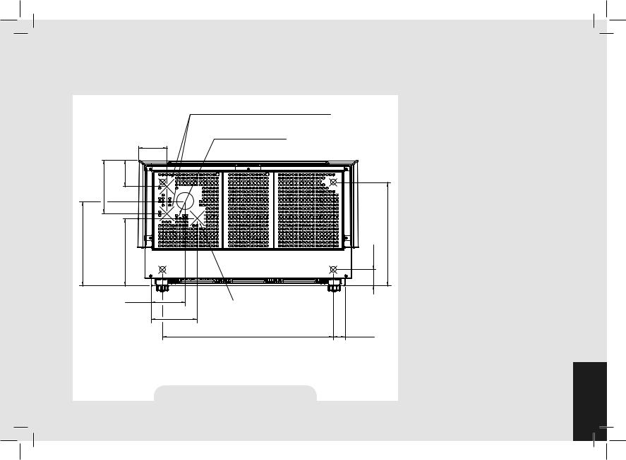
1) Installation on the counter |
|
|
|
|
|
|
|
2) Accessories |
|
|
|
|
|
||||
The image below shows the recommended method to drill the hole on the counter. |
|
|
|
Check the package to make sure that the |
|||||||||||||
|
|
|
|
|
|
|
|
|
|
|
following accessories are included: |
|
|
||||
|
|
|
|
|
|
|
|
|
|
|
• anumberof1-doseand2-doseportafilters |
||||||
|
|
|
|
HERE THE POSITION OF THE POWER CORD AND |
|
|
|
|
orresponding to the number of groups; |
||||||||
|
|
|
|
|
|
|
• |
replacement 1-dose and 2-dose filters |
|||||||||
|
|
|
|
WATER INLET HOSES |
|
|
|
|
|
||||||||
|
|
|
|
|
|
HERE THE POSITION WHERE WE |
|
|
(one of each); |
|
|
|
|
||||
|
|
|
|
FROM 100 TO 120 mm |
|
• |
1 tamper; |
|
|
|
|
|
|||||
|
|
|
135 mm |
FROM 4 in. TO 4,7 in. |
SUGGEST TO MAKE THE HOLE |
|
|
|
|
|
|
|
|||||
|
|
|
|
ON THE TABLE |
|
|
|
• |
1 blind filter; |
|
|
|
|
||||
|
|
|
|
|
|
|
|
|
|
|
|
|
|||||
|
|
|
5,3 in. |
|
|
|
|
|
|
|
|
|
|
||||
|
|
|
|
|
|
|
|
|
|
• cleaning detergent, for the groups; |
|
||||||
|
|
mm in. |
|
|
|
|
|
|
|
|
|||||||
mm in. |
|
|
|
|
|
|
|
• 3 stainless steel braided hoses for water |
|||||||||
123 |
4,8 |
|
|
|
|
|
|
|
|
connections; |
|
|
|
|
|||
|
|
|
|
|
|
|
|
|
|
|
|
|
|
|
|
||
250 |
9,8 |
|
|
|
|
|
|
|
|
|
• |
1,5 mt of |
reinforced plastic tubing |
for |
|||
|
|
|
|
|
|
|
|
|
|
drainage; |
|
|
|
|
|
||
|
|
|
|
|
|
|
|
|
|
|
|
|
|
|
|
|
|
mm400 in.15,7 |
|
mm318 |
in.12,5 |
|
|
|
mm78 |
|
412mm |
16,2in. |
• |
1 hose clamp. |
|
|
|
|
|
|
|
|
|
in.3 |
In order to proceed with installation, it is |
||||||||||||
|
|
|
|
|
|
|
|
|
|
|
|||||||
|
|
|
|
|
|
|
|
|
|
|
necessary that the following are available: |
||||||
|
|
|
|
|
|
|
|
|
|
|
• |
Pipes carrying drinking water with a |
|||||
|
|
|
|
|
|
|
|
|
|
|
|
3/8”G (BSP) end connection; (3/8” |
|||||
|
|
|
|
|
|
|
|
|
|
|
|
Compression for USA and Canada) |
|
||||
|
|
|
|
|
|
|
|
|
|
|
• Electrical |
Supply |
according |
to |
the |
||
|
|
|
160 mm |
HERE THE POSITION |
|
|
|
|
|
|
specification of the |
espresso |
machine |
||||
|
|
|
|
|
|
|
|
|
purchased: |
|
|
|
|
|
|||
|
|
|
OF THE DRAIN TUBE |
|
|
|
|
|
|
|
|
|
|
|
|||
|
|
|
6,3 in. |
|
|
|
|
|
|
|
|
|
|
|
|||
|
|
|
|
217 mm |
|
|
|
|
|
|
• |
Single/Three phase 220VAC - 50/60 |
|||||
|
|
|
|
8,5 in. |
|
|
|
|
|
|
|
Hz electrical connection with ground, |
|||||
|
|
|
|
565mm (2 groups) |
805 mm (3 groups) |
55 mm |
|
|
|
|
protected socket and approved interlock |
||||||
|
|
|
|
22,2 in. (2 groups) |
31,7 in. (3 groups) |
2,2 in. |
|
|
|
|
switch |
|
|
|
|
|
|
|
|
|
|
POSITION OF THE HIGH LEGS MACHINE |
|
|
|
|
|
|
|
|
|
|
|||
|
|
|
|
|
|
|
|
• |
Single phase 200VAC - 50/60 Hz |
||||||||
|
|
|
|
|
|
|
|
|
|
|
|||||||
|
|
|
|
|
|
|
|
|
|
|
|
electrical |
connection |
with |
ground, |
||
|
|
|
|
|
|
|
|
|
|
|
|
protected socket and approved interlock |
|||||
|
|
|
|
Fig. 4 - Hole on the Counter |
|
|
|
|
|
|
switch |
|
|
|
|
13EN |
|
|
|
|
|
|
|
|
|
|
|
|
|
|
|
|
|||
|
|
|
|
|
|
|
|
|
|
|
|
|
|
|
|
||
EN
•Three-phase, 380VAC - 50 Hz electrical connection with neutral + ground, near the bench on which the machine is installed and terminating in a suitable protected fivepole socket equipped with an approved interlock switch
•Waste water drain system.
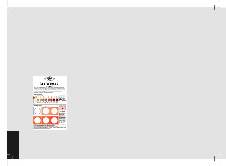
3)Water test kit
In order to enable you to check if your water supply is within the suggested ranges, La Marzocco machines will be equipped with two units of a quick water test kit (see image below) including 6 test-strips and instruction cards.
The parameters that you can measure are Total
Hardness, Total Iron, Free Chlorine, Total
Chlorine, pH & Total Alkalinity, Chlorides.
14
Ideally, you should perform a test on the water BEFORE the water treatment system and again AFTER the water system in order to verify if this is actually matching our suggested ranges.
Once the test has been performed, learn which treatment system is most appropriate for your particular water supply by filling out the online water calculator on our website: LA MARZOCCO WATER CALCULATOR (http:// www.lamarzocco.com/water_calculator/).
4) Water supply connection
In order to connect the machine up to the water mains proceed according to the indications given in the chapter about Installation and in compliance with any local/national safety standards of the location in which the machine is being installed. The equipment is to be installed with adequate backflow protection to comply with applicable federal, state, and local codes.
To guarantee a correct and safe functioning of the machine and to maintain an adequate performance level and a high quality of the beverages being brewed it is important that the incoming water be of a hardness greater than 7°f (70ppm, 4°d) and less than 10°f (100ppm, 6°d), pH should be between 6.5 and 8.5 and the quantity of chlorides be less than 50mg/l . Respecting these values
allows the machine to operate at maximum efficiency. If these parameters are not present, a specific filtration device should be installed, while always adhering to the local national standards in place regarding potable water.
Then connect the inlet of the water filter/ softener (if present) to the drinking water supply using one of the supplied stainless steel braided hoses. Before connecting the filter to the water pump, flush the water supply line and the filtration system in order to eliminate any residual particles which could otherwise get stuck in taps or valves thus preventing them from working properly. Connect the water supply connection of the espresso machine to the water pump outlet using one of the supplied stainless steel braided hoses. Then connect the water pump inlet to the water filter/softener outlet (if present).
Note:Thewaterpumpisadifferentialpressure volumetric pump and has been designed to be used exclusively with cold water. Make sure that water is always present while the pump is operating, otherwise air can be introduced into the brew boiler causing an undesireable condition and the pump can be damaged.
5) Electrical connections a) Power supply cord
• This is the main power supply cable
that provides power to the entire espresso machine. There are different types of cable based upon the electrical requirements of the espresso machine purchased:
•200/220VAC 1 Phase 3-core cable with 4/6/10mm2 cross section or AWG 12/10/8 for 2,3 4 group versions, secured to espresso machine via a strain relief connector
•220VAC 3 Phase 4-core cable with 4 mm2 cross section for 2 , 3 and 4 group versions, secured to espresso machine via a strain relief connector
•380 VAC 3 Phase 5-core cable with 2.5mm2 cross section for 2, 3 and 4 group versions, secured to espresso machine via a strain relief connector.
b) Water pump motor power cord
This is the power supply for the water pump motor. The internal electronics will switch the pump motor on when needed.
• 3-core cable with 1.5 mm2 cross section or 3-core AWG 16 (for UL version) secured to espresso machine via a strain relief connector.
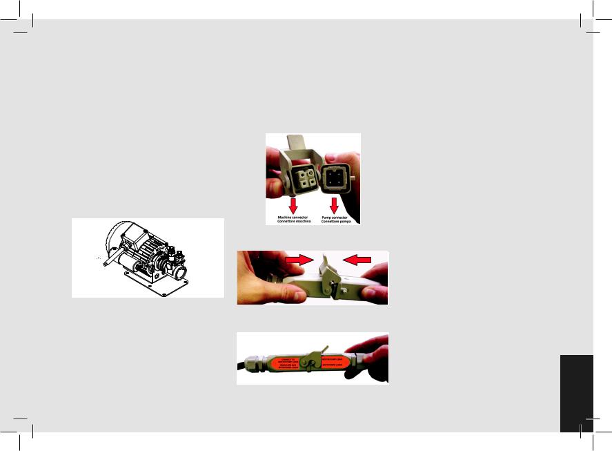
c) Quick connection between the water pump and the espresso coffee machine
The electrical connection must be made through the use of the connectors, as shown in the following figures:
- View of the connectors;
-Cable connection;
-Cable tightening;
6) Waste water drain connection
The espresso machine drain is to be connected by means of the included reinforced plastic tubing. Connect one end of the reinforced plastic tubing to the drain hose connection on the left side of the espresso machine, secure with included hose clamp. Connect the other end to a suitable waste water collection system.
In case such a system is not available, drained liquids may be collected in a suitable bucket and any necessary drain pipe extensions shall be made using steellined PVC tubing and suitable hose clamps.
15EN
EN
4. Machine Operation and Coffee Preparation
CAUTION
Never remove the filter holder when water is being delivered. This operation can be extremely dangerous since the high pressure built-up inside the blind filter would spray out hot and slightly caustic water, which may cause severe burns. The Coffee Boiler contains water at elevated temperature. Water temperature over 125°F / 52°C can cause severe burns instantly or death from scalding.
WARNING
The machine must not be dipped in, nor splashed with, water in order to clean it. For cleaning operations, please follow the instructions listed below very
carefully.
16
WARNING
This machine is designed only for preparing coffee and hot drinks.
IMPORTANT
To improve the flavor of the espresso, the temperatureofthewaterinthecoffeeboiler and therefore of the groups may eventually be raised or lowered via the digital display (please consult the Software Programming Manual for detailed instructions).
1) Starting the espresso machine
a) Filling the boilers with water
Once the installation procedures have been completed, it is necessary to fill the boiler tanks with water. Complete the following procedure to properly fill the boiler tanks:
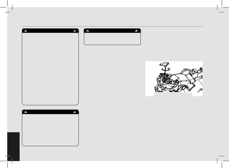
• Coffee boiler
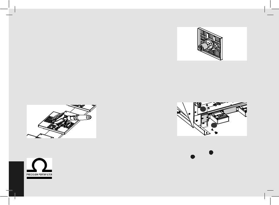
The water flows inside the coffee boiler directly, as soon as the water system and water filter/softener taps (if present) are opened. Since the inflow of water will compress the air in the boiler it will be necessary to remove or “bleed” the air from the coffee boiler. All air must be removed in order to completely “saturate” the coffee boiler/group assemblies. To remove the air from the boiler, “bleed the groups”, it will be necessary to remove the
group cover from the top of the machine. First remove the group tray from the top of the machine exposing the cup tray. Remove the screws securing the group cover and then remove it. Once removed the top of the groups will be exposed.
Loosen the bleed screws one at a time (see fig.5) to allow air to escape until water flows from below the screw head.
Fig. 5
Tighten the screw to stop the water from flowing. Over tightening can cause damage to the sealing washer and the group cover. Repeat this procedure for all groups. Once all air is removed from the coffee boiler, reinstall the group cover by following the removal instructions in reverse.
• Steam boiler
Turn the main switch (item 1 in Fig. 1) to position “1” or ON, the automatic steam boiler level gauge will be switched on, activating the auto-fill solenoid valve and the motor pump. This will fill the steam
boiler to a predetermined level and will shut off when full.
Note: It may happen that the air inside the steam boiler builds up pressure (which may be detected through the pressure gauge - item 2, fig. 1) when the water is allowed to flow in; this “false” pressure must be eliminated by opening the steam valves (item 8, Fig. 1).
b) Turning the espresso machine on
Once you have completed these procedures, check the display. Press enter to confirm that the preceding procedures are complete.
The installation is now complete and the espresso machine should be heating to the operating temperatures.
2) Waiting for the espresso machine to heat to operating temperature
During this time, it may happen that the pointer of the coffee boiler pressure gauge reaches as high as 14-15 bar. This may happen anytime that the heating element is in the on condition. In this case it is necessary to adjust the expansion valve (Fig. 3) in such a way that the pressure may never exceed 11-12 bar. In normal operating conditions, the coffee boiler pressure gauge can read anywhere from 0-12 bar.
When brewing, the pressure should be set to 9 bar.
When the steam boiler reaches operating
temperature, the light on the Hot water dispense button will light.
When the espresso machine is ready to operate all lights on the keypads will light.
3) Brewing after first installation
Once the first installation procedures are finished, before proceeding with brewing coffee, hot water and steam, please follow these steps:
-Engage the portafilters by inserting them into each group, brew water through each group for at least two minutes.
-Being careful to avoid burns, turn on each steam wand for at least one minute.
-Turn on the hot water valve for the time necessary to allow the following quantities of water to be brewed:
At least 1 liter for a 1/2 group machine At least 2 liters for a 3 group machine
4) Installing the portafilters
Install the portafilter(s) by inserting them into the group and lift the portafilter knob rotating it from top to bottom until the stop position is reached. When the portafilters are inserted properly, you can press any of brew buttons to start the flow of water
through the portafilter. You should allow hot water to pass through the empty portafilter(s) for a few seconds each time, in order to pre-heat the portafilter.
Note: It is important to leave the portafilters installed in the espresso machine when not in use. The portafilter must remain heated for the brew process to function correctly.
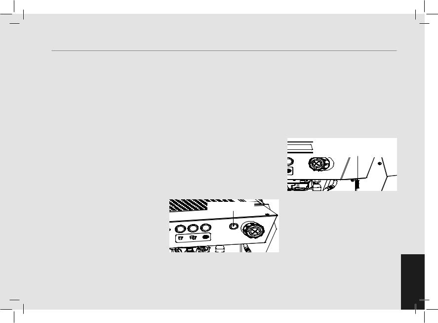
5) Water pump
Whenever you are brewing coffee, and you can adjust the pump pressure by turning the by-pass screw (below the plug located on the side to which the pump power supply is connected) clockwise to increase and counter-clockwise to reduce pressure. Adjust pressure only when at least one group is brewing coffee.
Note: When the heating element in the coffee boiler is energized, the water will expand increasing the start-up pressure. Once the maximum pressure is reached, the expansion (safety) valve should start working by discharging a few drops of water, in order to prevent such pressure from exceeding 11-12 bar.
In case the pressure exceeds 12 bar, you must adjust the expansion valve by unscrewing the cap slightly. If this is not sufficient, remove the valve and clear away any calcium deposits. This remedy is valid also in case the valve remains open in the drain position (i.e. the pressure cannot
increase to 8 bar approx.). EN
17
EN
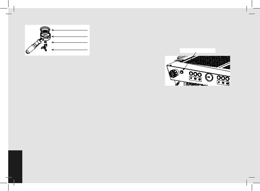
Filter Basket
Porta Filter
O-ring Gasket
Double Spout
6) Brewing coffee
It is now possible to remove one of the portafilters to make an espresso beverage. Place some ground coffee in the filter itself: 1 dose (approximately 6-7 g) for the small filter, 2 doses (2 approximately 1215 g) for the larger filter. Press down on the ground coffee with the supplied tamper and install the filter holder up again to the bottom of the group and then press a button to begin the brewing process.
Note: Some baristas believe it is important to press the brewing button prior to installing the portafilter to allow the water to flush any remaining coffee oils and particles from the group. Some also flush just after brewing coffee for the same reason. Please experiment to find the best possible procedure for you.
7) Controlling the brew process using volumetric programming
This espresso machine allows the volumetric programming of each of the first two buttons on each group (numbered left to right). Please consult the
18
Software Programming Manual for further instructions.
8) General notes for coffee preparation
The portafilters must remain heated since they are at the lowest position of the group itself, and they are partially isolated due to the rubber gasket between them. This can be accomplished by leaving the portafilters installed in the machine when not in use. The portafilters may also be actively heated. This procedure may be carried out by brewing some hot water through the portafilter then turning off the water flow, before making coffee.
It is important to remember that coffee left over in the filters must be removed only when you need to prepare another cup, and only at that time should you place a new dose of ground coffee in the filter.
The size of the coffee granules is extremely important in preparing a good cup of coffee, other than the type of coffee mix used, quite obviously. The ideal grinding can be determined by making various coffees using the amount of ground coffee that you would normally use for each cup (we recommend at least 6-7g). The best grinding is that which allows coffee to flow out from the filter holder spouts neither too slowly (drop by drop) nor too quickly (quick light brown flow). A general rule is that a double dose should dispense approximately 25cc or 2 fluid oz. of espresso in approximately 25 seconds.
9) Cup Warmer
Press Cup Warmer Button for enabled or disabled the cup warmer. This function work in two modes continuous or timed (see the Software Programming Manual for further instructions).
Cup Warmer Button
10) Autoclean and Autopurge
If the autoclean function is enabled in the menu, steam will be delivered by the group with a delay of 2 seconds form portafilter removal.
If the autopurge function is enabled in the menu, hot water will be delivered by the group with a delay of 2 seconds form portafilter removal.
If the autoclean and autopurge functions are both enabled in the menu, steam and then hot water will be delivered by the group with a delay of 2 seconds form portafilter removal.
5. Dispensing Steam and Hot Water
1) Steaming milk or other liquids
In order to allow for any condensed water in the wand to be released ALWAYS allow some steam to be discharged by turning on the valve before inserting the steam wand into the pitcher of liquid to be heated.
Dip one of the 2 steam wands (part 7, fig. 1) which are connected to the steam valve, into the liquid to be heated, turn the steam knob (part 8, fig. 1) gradually until steam comes out at the end of the wand. The steam will transfer heat to the liquid raising its temperature up to boiling point. Be careful not to allow liquid to overflow in order to avoid severe burns.
In order to prevent the heated liquid from being sucked back into the steam boiler it is recommended before using the wand that you purge the steam valve and steam wand by opening the valve for a few seconds to allow steam to escape to the atmosphere from the end of the steam wand. Failure to do so can cause the heated liquid to transfer from the heated liquid container to the steam boiler (via vacuum created from cooling parts). This condition is undesireable and can cause contamination in the steam boiler. After use remember to purge the wand by opening the steam valve for a few seconds, and then clean the outside of the wand
itself with an appropriate cloth.
In order to prepare milk for making cappuccino with the right amount of foam, go through the following steps:
• After purging the steam wand place the container half-full of milk underneath, carefully open the steam valve and raise the container so as to bring the wand end to a point just below the surface of the milk; at this point, move the container up and down just enough to dip the nozzle end in and out of the milk until you get the right amount of foam, bring the temperature of the milk almost up to 149/158°F or 65/70°C. You can then pour this milk into a cup containing warm espresso and you will end up with a fresh cup of cappuccino.
2) Preparing hot water and other hot drinks
HOT WATER
You may dispense hot water by using the fixed nozzle (item 9 fig 1). To dispense hot water, press the hot water button on the right most group.
This button commands the hot water delivery.
The volume of water delivered may be adjusted via the display (see the Software Programming Manual for further instructions). The temperature of the water dispensed may be adjusted by adjusting the mixing valve under the right side cover of the espresso machine. (only on the models of espresso machine equipped with this accessory)
HOT WATER MIX VALVE
19EN
6. Maintenance and Periodic Cleaning Operations
EN
WARNING
If the above-mentioned instructions are not adhered to the manufacturer cannot be held responsible for damage to persons or things.
WARNING
In order to prevent cracks or leakage: do not store or install the coffee machine in places where temperature may cause water in boiler or hydraulic
system to freeze.
WARNING
The machine is intended to be permanently connected to fixed wiring, and it is advisable that a residual current device (RCD) with a rated residual operating current not exceeding 30mA is
installed.
20
WARNING
The machine must be installed so that qualified technical presonnel can easily access it for eventual maintenance.
WARNING
The machine must not be dipped in, nor splashed with, water in order to clean it. For cleaning operations, please follow the instructions listed below very
carefully.
WARNING
Do not remove the filter holder while relative group is brewing hot liquids.
The Coffee Boiler contains water at elevated temperature. Water temperature over 125°F / 52°C can cause severe burns instantly or death from scalding.
WARNING
This machine is for professional use only and should be installed in locations where its use and maintenance is restriced to trained personnel.
WARNING
Jets of water should not be used to clean the machine, nor should it be placed where water jets are used.
1) Cleaning groups and drain wells
-Put a tablespoon of detergent powder for coffee machines into the blind filter, supplied with the machine, and tighten it onto the group you want to clean by using a normal filter holder.
-Activate the automating rinsing (backflushing) routine (see the Software Programming Manual for more detailed instructions).
-Rinse the group using a normal filter, by running hot water through it several times
2) Cleaning filters
-Put 2 or 3 teaspoons of detergent powder for coffee machines in about 1/2 a litre of water inside a heat-resistant container and boil.
-Dip filters in the boiled solution and leave them fully submerged for about 30 minutes.
-Rinse thoroughly with clean water and run hot water through one group several times with the filters in place.
-Make one cup of coffee and discard in order to remove any unpleasant flavor.
3) Cleaning filter holders (portafilters)
Using the proper cleaning tool (brush) wash the filter holders under hot water, a neutral detergent may also be used.For extraordinary cleaning see the Portafilter Manual.
4) Cleaning the drain collector
Remove the drain tray grill at least twice a week and clean, pull out the water drain collector and clean it thoroughly. Inspect and clean also the drain box and remove any leftover grounds.
5) Cleaning the body
Wipe the stainless steel surfaces with a soft, non abrasive cloth in the direction of the glazing marks, if any. Do not use any alcohol or solvents whatsoever on painted
or imprinted parts in order not to damage them.
6) Cleaning the hot water and steam nozzles
Steam nozzles must be cleaned immediately after use with a damp cloth and by producing a short burst of steam so as to prevent the formation of deposits inside the nozzles themselves, which may alter the flavor of other drinks to be heated. Hot water nozzles must be cleaned periodically with a damp cloth.
7) Cleaning the diffuser screen
-Due to filter holder discharge operations (subsequent to coffee brewing), a certain amount of coffee grounds may slowly build-up on and obstruct, even partially, the diffuser screen. To clean it, you must first remove it by unscrewing the diffuser screw.
-Put 2 or 3 teaspoons of cleaning detergent for coffee machines in about 1/2 a litre of water inside a heat-resistant container and boil.
Group
Assembly
Diffusor
Screen
Diffusor |
Screw |
- Place the diffuser screen(s) and diffuser screw(s) in the solution and leave them fully submerged for about 30 minutes. Rinse thoroughly with clean water. Install and run hot water through each group several times with the screen installed.
8) Cleaning the portafilter group
After pressing the straight-in release lever, it is possible to use a non-abrasive soft cloth to clean the portafilter support.
Do not use aggressive solvents on varnished parts or plastic parts to avoid damage. Clean the cover panels using a soft cloth. Only clean with a wet cloth or with a cloth soaked with warm water and neutral soap.
Straight-in Release Lever
21EN

Portafilter Support
9) Water Filter/Softener
Please see the documentation accompanying the water filter/softener for proper operating and cleaning instructions.
•Steamboilerdraining:to activate this function you need to access the programming menu (see page 104). Yearly, we recommend to fully drain the steam boiler by means of the specific drain cock located on the side of the boiler or under the boiler.
10) Depressurize the steam boiler
Press and hold the encoder knob to set the espresso machine to “OFF”, then push down the steam lever in order to depressurize the steam boiler.
IMPORTANT
If the machine has not been used for more than 8 hours or, in any case, after long periods of being idle, in order to use the machine to its full potential it is necessary to perform some cleaning cycles before brewing beverages as follows:
-Groups: with the portafilters engaged in the groups brew water through each for
at least two minutes
- Being careful to avoid burns, turn on each steam wand for at least one minute.
-Turn on the hot water valve for the time necessary to allow the following quantities of water to be brewed:
At least 1 liter for a 1/2 group machine At least 2 liters for a 3 group machine
If the machine is not going to be used for long periods of time, it is advisable to follow these safety indications:
-Disconnect the machine from the water mains or interrupt the water connection via a mains tap.
-Disconnect the machine from the electrical mains.
EN
22
7. De-commissioning and Demolition
1) De-commissioning and demolition
Start by setting the main switch to the “0” or OFF position.
Disconnecting from the power outlet
Disconnect the espresso machine from the electrical network by switching off the associated circuit breaker or circuit protection device. Remove the power supply cord from the power connection. Remove the Pump Motor Power Cord from the water pump motor.
Disconnecting from the water system
Shut off the water supply by closing the specific tap located upstream of the water filter/softener inlet. Disconnect the water pipe at the water filter/softener inlet.
Remove the hose connecting the espresso machine to the water pump. Remove the reinforced plastic tubing on the drain connection.
At this point, the machine may be removed from the bar, being very careful not to drop it or squash your fingers.
The machine is made out of various materials and therefore, if you do not intend to put it back in service, it must be taken to a special disposal company which will select the materials which can be recycled and discard the others.
Current regulations make it illegal to discard such machine by leaving it on public grounds or on any private property.
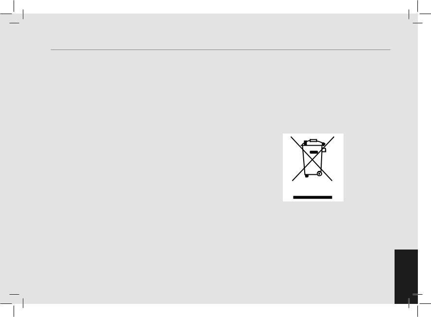
Recycling notice: Warning for the protection of the environment.
Used Electrical and electronic waste contains hazardous but also valuable and scarce materials which should be recovered and recycled properly. We kindly ask that you contribute to the protection of the environment and natural resources by delivering used equipment to the relevant recycling locations if such locations are available in your country.
23EN

8. Mandatory Maintenance and Check-up Operations
These operations are in addition to the Maintenance and Periodic Cleaning Operations as specified in Chapter 6.
The following maintenance and check-up operations sould be carried out by a qualified technician.
The time required for the periodic maintenance is determinated by the quantity of daily work and/or coffee consumption.
N.B. These periodic maintenance operations are not covered by warranty.
|
EVERY THREE/FOUR MONTHS |
|
▪▪ Replace group gaskets |
▪▪ Check brew temperature |
on Installation, otherwise |
▪▪ Replace diffuser screens |
▪▪ Check that brew pressure is |
warranty is voided) |
▪▪ Clean auto-fill probe |
at 9bar |
▪▪ Check filter basket condition |
▪▪ Check vacuum breaker for |
▪▪ Check all switches for proper |
▪▪ Check shot volumes |
proper operation |
operation |
▪▪ Test flowmeter’s ohm value |
▪▪ Inspect water inlet valve |
▪▪ Check/note water hardness |
(ohm value is acceptable if |
▪▪ Inspect drain system for leaks |
▪▪ (Water quality must be within |
greater than 1.8 K ohm, and |
or clogs |
the range of parameters |
less than 2.2 K ohm |
▪▪ Check flow rate for each group |
specified in the chapter |
|
EVERY SIX/EIGHT MONTHS (in addition to the above)
▪▪ Rebuild steam assemblies
EN
▪▪ Replace portafilter baskets |
EVERY YEAR (in addition to the above) |
|
condition |
each cable on the terminal |
|
▪▪ Inspect group valve plungers |
▪▪ Inspect boilers safety switches |
block. |
▪▪ Inspect vacuum breaker |
▪▪ Replace over-pressure valve |
|
▪▪ Inspect contactor |
(safety valve) |
|
▪▪ Inspect expansion valve |
▪▪ Accurate control of the |
|
▪▪ Inspect electrical wiring |
tightness at 2,4Nm of |
|
|
|
|
EVERY 3 YEARS (in addition to the above)
▪▪ Check the condition of the inside of boilers and if necessary rinse out with a proper cleaning product allowed for food and beverage appliances.
24
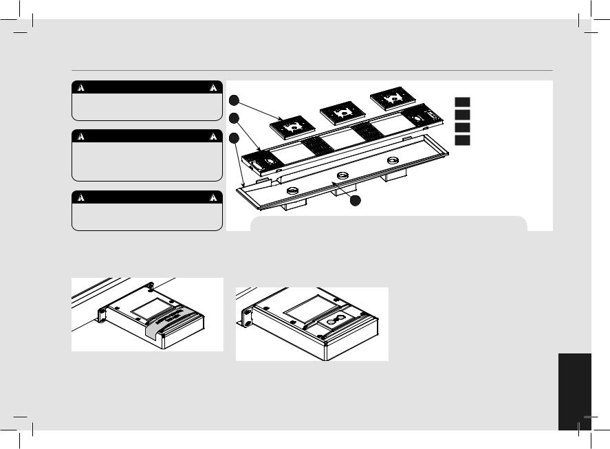
9. Precision Scale
WARNING
Handle with care maximum load 1Kg do not lift.
WARNING
The individual grid of the scale is a fragile component, handle and store with care.
WARNING
The height of the bottom tray is fixed.
1) Use precautions
Remove the adhesive label with care; if needed, remove any adhesive residues from the surface using a neutral detergent.
Don’t spill |
water |
onto the |
scale |
box |
If needed, |
gently |
remove it |
with |
an |
absorbent cloth. Should any water and/or dirt penetrate into the holes highlighted
|
Legend |
|
|
3 |
1 |
Scale crosspiece |
|
2 |
2 |
Drain grille |
|
3 |
Scale individual grid |
||
|
|||
1 |
4 |
Removable drain tray |
4
Fig. 6 - Precision Scale - 2, and 3 brewing groups
in the figure below, gently clean and dry them with an absorbent paper cloth.
Dirt build-up or water stagnation may prevent the scale individual grid from properly settling into place.
The weighing system in static conditions
(*) has a rated accuracy of ±0.5g. For correct operation, make sure that:
•Maintenance is performed properly, by an authorized person and in the manner prescribed in this manual;
•Please use the machine according to the instructions specified in this manual;
•Please make sure the machine is installed on a level and firm counter;
•Please make sure the power supply is stable and without electrical noises.
The weighing stage is a inherently delicate, in fact it is affected by:
• Vibration of the bench caused for example by other devices;
• Machine vibrations caused, for example,
by the use of the adjacent group.
25EN
(*) Static weighing means weighing an object whose weight is fixed during the entire weighing.
The machine is not a weighing device certified for legal weighing.
-The weighing system is a precision device that requires a lot of caution in terms of use, cleaning and maintenance.
-Should the main grid or tray be removed, ensure not to hit the load cells during the disassembly and reassembly operations.
-To proceed with the weighing of the filter holder either empty or filled with coffee powder, place it as shown below:
- Use only original La Marzocco filters and filter holders, identified by the following symbol:
-Use only filter holders with double spout;
-Do not place on the scale objects weighing more than 1kg;
-Never load more than 1 kg, to prevent any damage to the scales;
-Use the high precision scale with care, avoid shocks, falling objects and sudden load peaks;
-Any object to be weighed must be placed correctly on the scales grid.
2) Cleaning
-The cleaning of the “individual grids” must be performed with care, without overloading the cells;
-For proper weighing of the filter holder, make sure the grid is clean and dry;
-To avoid contact with dirt before placing the filter holder, clean and dry the grid;
-Please be careful during the cleaning procedures to avoid the water dripping on the scale and its electrical components;
-Don’t wash the scale individual grids in a dishwasher; wash them manually instead, then immediately dry them.
If you wash the grid under a strong water flow, remove the magnetic support highlighted in the figure (just pull to detach the magnets). Make sure that the magnets are always dry and clean.
- To clean the drain tray you need to remove the individual grids (part 3, figure 6) first, then the drain grille (part 2, figure 6) and finally the tray (part 4, figure 6). Make sure not to hit the load cells during the disassembly and reassembly operations.
3) Removing the electronic box
2
 1
1
To remove the electronic box you need to remove the drain tray, unscrew and remove the lower screws 1 , loosen the upper screws 2 without removing them and move the scale crosspiece up. Now you can access the electronic box or remove it.
EN
26

10. Straight-in
1) Installing the portafilters |
|
|
1 |
2 |
3 |
|
|
Rotate |
|
|
Insert |
Straight-in
2) Removal the portafilters |
|
|
|
1 |
Press |
2 |
3 |
Extract
27EN
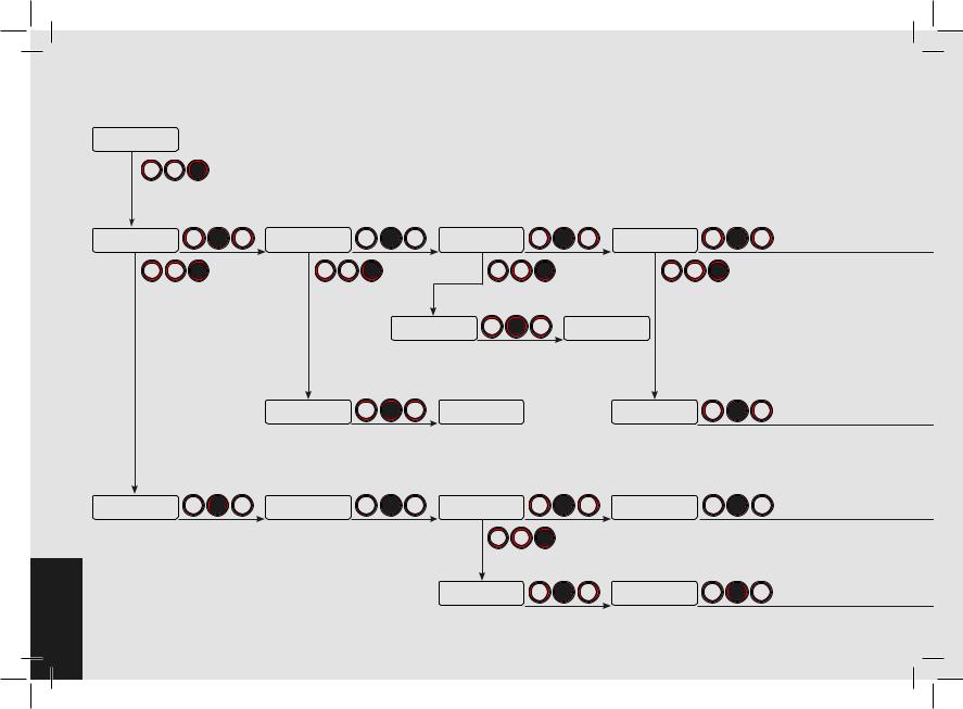
11. Software Programming Guide |
“Barista” Programming |
94.400:00
95.595.1 SB
page 32
PUSH
Press and hold the T3 button for 5 seconds.
Group Dose |
PUSH |
|
Settings |
||
|
page 41
PUSH
Program |
PUSH |
|
Volume Dose |
||
|
page 41
EN 28
Scale |
PUSH |
Water Dose |
|
PUSH |
Coffee Boiler |
PUSH |
Configuration |
Settings |
|
Settings |
|||
|
|
|
|
|||
page 55 |
|
page 57 |
|
|
page 60 |
|
|
PUSH |
|
|
PUSH |
|
PUSH |
|
|
Water Dose |
PUSH |
|
Water Dose |
|
|
|
ENABLED |
|
Exit |
|
|
|
|
|
|
|
||
|
page 57 |
|
page 59 |
|
||
Scale Tare Time |
PUSH |
Scale Settings |
|
Coffee Boiler 1 |
PUSH |
|
3s |
Exit |
|
|
ENABLED |
||
|
|
|
|
|||
page 55 |
|
page 56 |
|
|
page 60 |
|
Program |
PUSH |
G1 Dose |
PUSH |
Copy |
PUSH |
|
Mass Dose |
Settings |
Dose |
||||
|
|
|
||||
page 43 |
|
page 45 |
|
page 51 |
|
|
|
|
|
PUSH |
|
|
|
|
|
Group 1 Mode |
PUSH |
G1B1 Dose |
PUSH |
|
|
|
PULSES |
30 |
|||
|
|
|
|
|||
|
|
page 45 |
|
page 46 |
|
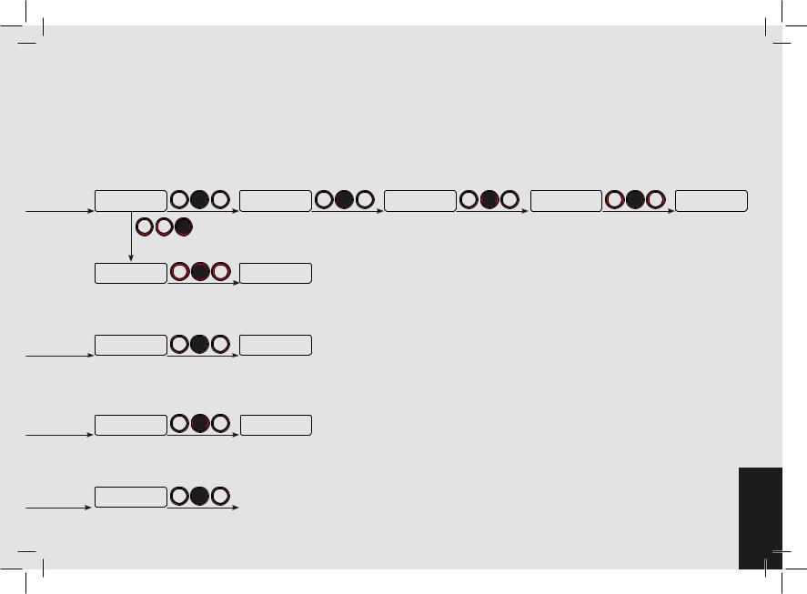
“Barista” Programming
Pre-Inf |
PUSH |
|
Settings |
||
|
page 62
PUSH
Group 1 Pre-Inf |
PUSH |
|
0s Wet 0s Hold |
||
|
page 62
CB1 Temperature |
PUSH |
||
94,5°C |
95,0°C |
||
|
|||
page 61
Reset |
PUSH |
|
Volume Doses |
||
|
page 53
Exit |
PUSH |
|
Group 1 |
||
|
page 46
Cup Warmer
DISABLED page 64
Pre-Inf Settings
Exit page 63
CB Settings
Exit page 61
Group Dose
Exit page 53
PUSH
Auto Clean
ENABLED page 66
PUSH |
Auto Purge |
PUSH |
Exit |
|
ENABLED |
Menu |
|||
|
|
|||
|
page 68 |
|
page 70 |
29EN
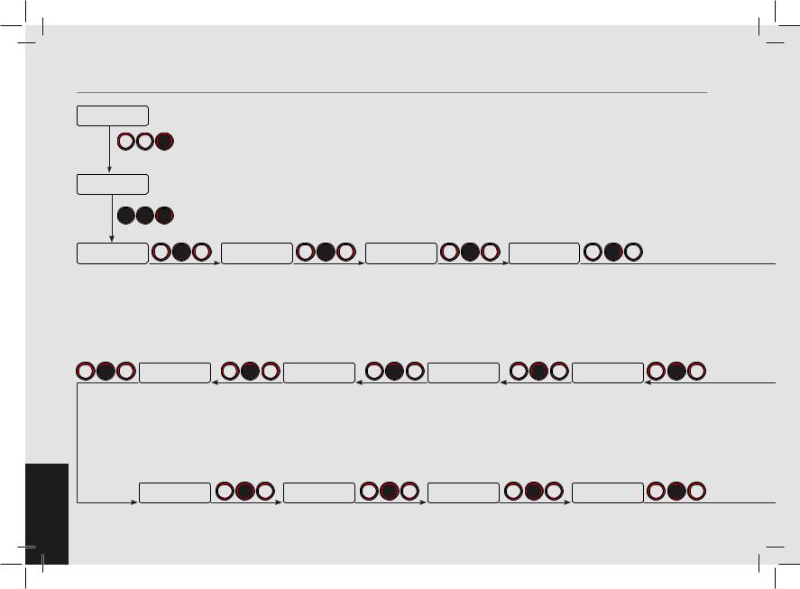
“Technical” Programming
94.400:00
95.595.1 SB
page 32
PUSH |
Press and hold the T3 button for 10 seconds. |
Enter Password
page 38 |
|
|
|
|
|
|
PUSH |
PUSH |
PUSH |
|
|
|
|
Language |
|
PUSH |
Temp Units |
PUSH |
Name |
PUSH |
ENGLISH |
|
CELSIUS |
LaMarzocco |
|||
|
|
|
|
|||
page 71 |
|
|
page 73 |
|
page 75 |
|
Group Dose
Settings page 77
PUSH
PUSH
EN 30
Auto Purge
ENABLED page 125
Coffee Dose
Counter page 127
PUSH
PUSH
Auto Clean
ENABLED page 123
Filter Alarm
Settings page 130
PUSH
PUSH
Eco Mode
Settings page 121
Reset
Settings page 133
PUSH
PUSH
Auto On/Off
Settings page 118
Update
Firmware page 135
PUSH
PUSH
 Loading...