


Model: 308-1451H
Instruction Manual
DC: 040214
Wireless Forecast Station
La Crosse Technology, the world leader in atomic time and weather instruments, introduces the perfect Wireless
Forecast Station for avid outdoorsmen. The advanced forecast icons feature a hunter icon who suggests what to
wear to prepare for the outdoor temperature. The wireless temperature and humidity sensor monitors backyard
conditions for precise, real-time weather. Track sunrise, sunset, moon phase, and monitor both indoor and
outdoor humidity and temperature all on this easy-to-read display. Additional features include atomic time & date
(sets itself), dual time alarms, barometric pressure in numbers, pressure graph with 12-hour history, and
high/low temperature and humidity alarms.
Forecast Station & Outdoor Sensor
Forecast Icon
with Tendency
Hunter icon
suggests what to
wear to prepare
for the current
outdoor
temperature.
Absolute Pressure
+ History
12-hour Pressure
History Graph in
hPa or inHg
Get Started
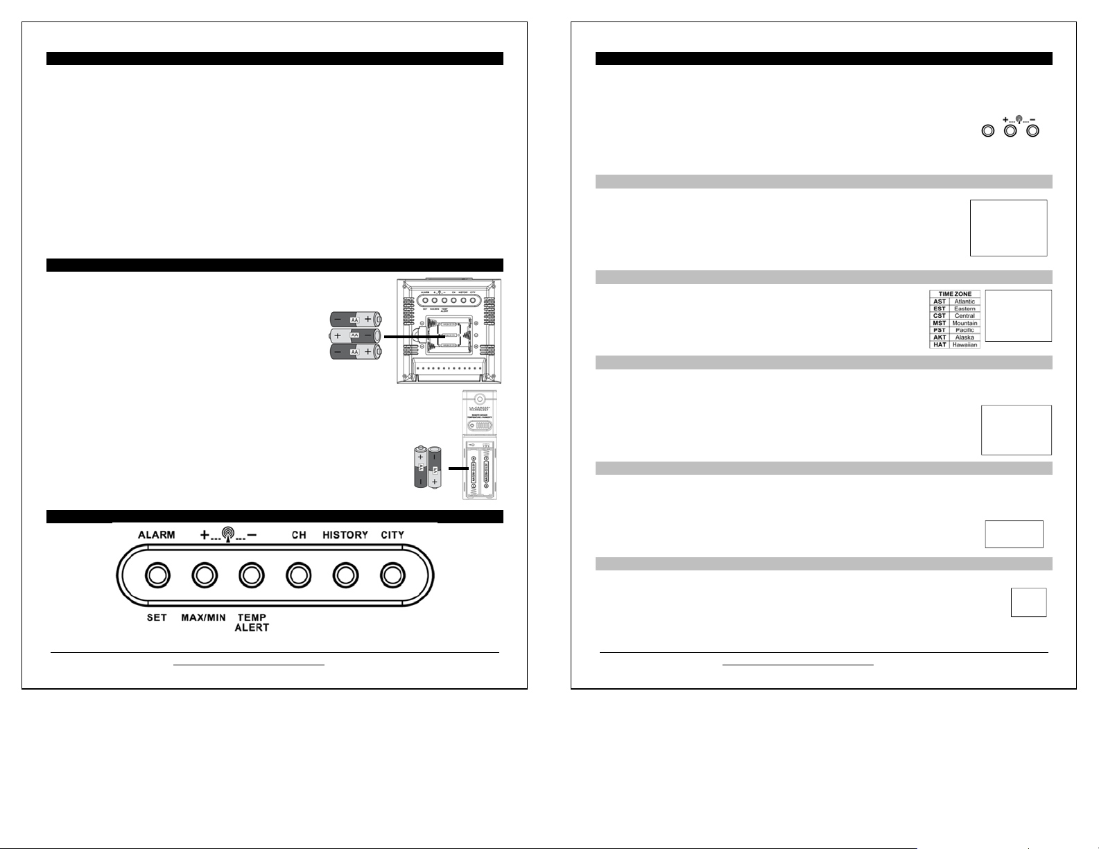
Step 1: Insert 3 NEW AA batteries (not included) into the forecast station. Observe the correct polarity.
Step 2: Insert 2 NEW AA batteries (not included) into the outdoor sensor. Observe the correct polarity.
The red LED light will flash when transmitting.
Restart: if there is no outdoor temperature data after 3 minutes.
Remove batteries from the forecast station & sensor for 15 minutes.
Return to Step 1 above.
Model: 308-1451H
www.lacrossetechnology.com/support
Time with
2 Alarms +
WWVB Icon
Calendar
Sunrise/sunset
Times with
Moon Phase
Indoor
Temperature,
Humidity
+ Alerts
Outdoor
Temperature,
Humidity
+ Alerts
TX142TH
1
Table of Contents
Forecast Station & Outdoor Sensor 1
Get Started 1
Table of Contents 2
Features 3
Install Batteries in the Forecast Station & Sensor 3
Function Buttons 3
Program Menu 4
WWVB Reception ON/OFF 4
Time Zone 4
DST Indicator ON/OFF 4
12/24-Hour Time Format 4
Fahrenheit/Celsius 4
Set Time 5
Set Calendar 5
City Selection: Sunrise/Sunset Times 5
Tide 6
Moon Phase 6
Comfort Statement 6
Backlight 6
Alarms 7
Time Alarms 7
Set Time Alarm 1 7
Set Time Alarm 2 7
Snooze 7
Frost Alarm 7
Outdoor Temperature Alarms 8
Set Temperature Alarm 1 8
Set Temperature Alarms 2 and 3 8
Temperature Trend Indicators 8
Pressure Readings 8
Absolute Barometric Pressure Number 8
Pressure Unit of Measurement 9
Pressure History 9
Pressure History Graph 9
MIN/MAX Data 9
Low Battery Indicator 9
Weather Forecast & Hunter Icons 10
Weather Forecast (Snow, Sun, Partial Sun, Cloud, Rain) 10
Tendency Indicators 10
Hunter Clothing Index 10
Channel Selection and Auto-scroll 11
Use Multiple Sensors 11
WWVB Radio-controlled Time 11
WWVB Reception Icon 12
WWVB Manual Signal Search 12
Care and Maintenance 12
Position the Outdoor Sensor 12
Position the Forecast Station 13
Specifications 13
Warranty Information 14
FCC Statement 14
City Codes 15
Model: 308-1451H www.lacrossetechnology.com/support 2
Features
Forecast icons change with barometric pressure (Snow, Sun, Partial Sun, Clouds and Rain)
Advanced Hunter icon reacts to changes in outdoor temperature
Barometric pressure with 12 hour history graph (inHg or hPa)
Atomic 12/24 hour time and calendar: day, month, date (manual set option)
Sun rise/set, moon phase for 250 pre-selected US cities
Indoor temperature (ºF/ºC)
Indoor humidity (%RH)
Outdoor temperature (ºF/ºC)
Outdoor humidity (%RH)
Temperature and frost alarm icons
Time alarm with snooze
Indoor comfort level icon
Temperature and humidity trend arrows
Blue LED backlight
Low battery indicators
Monitor up to 3 separate sensors (sold separately)
Install Batteries in the Forecast Station & TX142TH Sensor
Forecast Station:
1. Remove battery cover. Slide tab to the right and pull out to remove battery
cover.
2. Install three new AA batteries according to the polarity
markings.
Do Not Mix Old and New Batteries
Do Not Mix Alkaline, Lithium, Standard or Rechargeable
Batteries
Outdoor Sensor:
1. Slide the battery cover down, then lift off the front of the TX142TH sensor.
Note: Be careful not to break the tabs on the battery cover.
2. Confirm the channel selector switch is on channel 1.
3. Insert two new AA batteries into the sensor.
Observe the correct polarity (see marking inside battery compartment).
4. Keep sensor 5-10 ft. from the forecast station during setup.
5. After 15 minutes, if the outdoor temperature shows on the forecast station, move the
outdoor sensor outside to a shaded location within range of the forecast station.
Function Buttons (on back of forecast station)
Model: 308-1451H
www.lacrossetechnology.com/support
Program Menu (sets time, calendar, 12/24 hour time, °F/°C, and WWVB reception)
The SET button will moves through the items in the program menu. The
WWVB reception ON or OFF
Time Zone (Seven Time Zones)
Daylight Saving Indicator
12/24 hour time format
Fahrenheit/Celsius selection
Manual time set (Hour, Minutes, Seconds)
Calendar set (Year, Month, Date)
WWVB Time Reception
The WWVB time reception defaults to ON. To turn the WWVB reception OFF:
1. Hold the SET button for 5 seconds.
2. WWVB and ON will flash in the time display.
3. Press and release the + or - button to turn this OFF.
4. Confirm with the SET button and move to the Time Zone.
Time Zone
This station offers seven time zones listed in letter format (default is EST):
1. EST will flash next to the date.
2. Press and release the + or - button to select a different Time Zone.
3. Confirm with the SET button and move to Daylight Saving Indicator.
DST Indicator
DST will default to the ON position as most of the country observes the DST change. The DST indicator should
stay on all year so the forecast station knows when to switch into or out of daylight saving time. If you live in an
area does not observe the DST change, switch this to the OFF position.
1. DST and ON will flash in the time display.
2. Press and release the + or - button to turn DST to OFF.
3. Confirm with the SET button and move to 12/24 hour time format.
12/24 Hour Time Format
The time may be displayed in 12-hour or 24-hour format. Default is 12-hour time.
Note: When in 12-hour format AM or PM will show in front of the hour.
1. 12Hr will flash in the time display.
2. Press and release the + or - button to select 24-hour time.
3. Confirm with the SET button and move to Fahrenheit/Celsius.
Fahrenheit/Celsius
Select the temperature to display in Fahrenheit or Celsius. Default is Fahrenheit.
1. °F will flash in the time display.
2. Press and release the + or - button to select Celsius.
3. Confirm with the SET button and move to Set Time.
+ or -
button will change these values.
On
SET
TIME ZONE
EST
On
12Hr
WWVB
DST
°F
3
Model: 308-1451H
www.lacrossetechnology.com/support
4
Set Time
A
To set the time manually:
1. The hour digit will flash.
2. Press and release the + or - button to select the hour.
3. Press and release the SET button to move to the minutes.
4. The minute’s digit will flash.
5. Press and release the + or - button to set the minutes.
6. Press and release the SET button to move to the seconds.
7. The second’s digit will flash.
8. Press and release the + or - button to reset the seconds to zero.
9. Confirm with the SET button and move to Set Calendar.
Set Calendar
To set the calendar:
1. The year will flash.
2. Press and release the + or - button to set the year (between year 2010-2039).
3. Press the SET button again to confirm and to enter the month setting.
4. The month will flash.
5. Press and release the + or - button to set the month.
Press the SET button again to confirm and enter the date setting
6.
7. The date will flash.
8. Press and release the + or - button to set the date.
9. Confirm all calendar settings with the SET button to confirm and exit the program menu.
Note: If no buttons are pressed for 20 seconds, set mode will time out and return to live display mode, reflecting
whatever adjustments were made before it timed out.
Note: Press the + or - button once to adjust by 1 unit or hold for fast scroll adjustment.
City Selection: Sun rise/set Times
Note: Preset city abbreviations are at the end of this
manual.
Choose the city closest to you in a north/south direction.
This will provide the most accurate sunrise/sunset times.
To select a city location: Select your country, state, and then city location.
1. Hold the CITY button for 5 seconds.
2. USA will flash next to the sunrise/sunset time.
3. Press and release the + or - button to select USA, CAN or MEX as your country.
4. Press the CITY button to confirm the country and select a state.
5. The state will flash. Press and release the + or - button to select a state.
6. Press the CITY button to confirm the state and select a city.
7. The city location will flash.
8. Press and release the + or - button to select a city from the list at the end of this manual.
9. Press the CITY button to confirm and exit.
After a short calculation time, the forecast station shows the times for sunrise and sunset,
moon phase and lunar tide.
CITY
Note: When either Canada or Mexico is chosen, you will move directly to city selection.
.
USA
K
ANC
Model: 308-1451H
www.lacrossetechnology.com/support
5
Note: When DST is in affect the forecast station will need to receive the WWVB time signal to make the
adjustment for DST. The WWVB signal includes an embedded bit to tell the station to adjust for DST. Until that
signal is received the first time, the sunrise/sunset times will be one hour off.
Tide
The tides reflected on this station are based on the ebb and neap tides of the lunar month rather than the daily
high and low tides. When the sun, moon and earth are lined up at new and full phases of the moon, tides will be
higher. When the moon is at right angles to the sun and Earth at the first and last quarter, the tides are weaker.
Full & new moon = spring tide (TIDE HI)
Quarter = neap tide (TIDE LO)
Other = mean water level (TIDE MID)
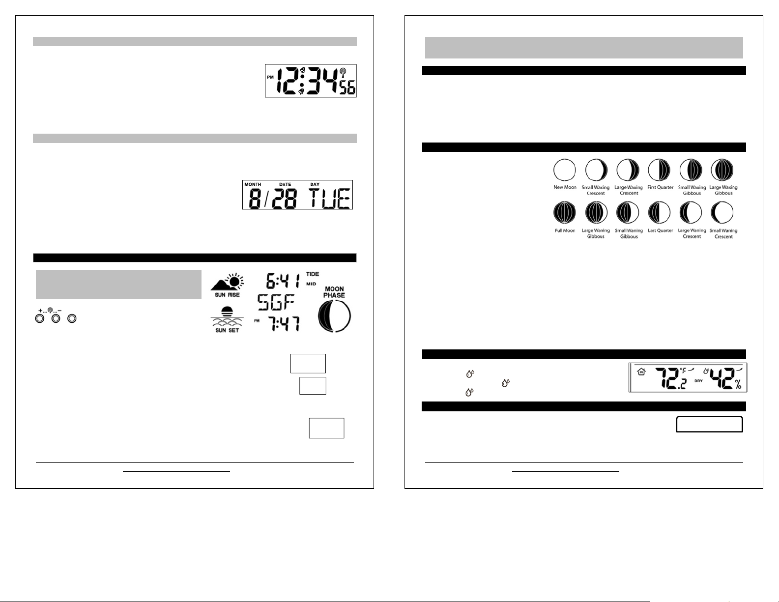
Moon Phase
The LCD Moon phase is divided by 6
sections, showing a total of 12 phases of
the moon.
Note: With the moon shown against a
light colored background, the phases will
show opposite to a paper calendar. The
segments that are highlighted portray the
part of the moon that is lit. For instance,
the moon will be blank during a new
moon and dark during a full moon.
New Moon occurs when the moon is between the earth and sun so the illuminated portion of the moon is on
the back side facing the sun and we cannot see it. After a new moon, the illuminated (visible) portion will
increase or wax until the full moon occurs.
Full Moon occurs when the earth, moon and sun are in approximate alignment, with the moon and the sun
on opposite sides of the earth. The illuminated portion of the moon faces the earth, giving us complete
visibility of one side of the entire moon. After a full moon, the illuminated portion will decrease or wane until
the new moon occurs.
First Quarter and Last Quarter moons occur when the moon is at a 90 degree angle to the earth and sun.
So we see half of the moon illuminated and half is in shadow.
Waxing means growing or expanding illumination and happens after a new moon.
Waning means decreasing illumination and occurs after a full moon.
Crescent refers to the moon being less than half illuminated. Crescents can be waning or waxing.
Gibbous describes a moon phase when more than half is illuminated. Gibbous can be waxing or waning.
Comfort Statement
The comfort statement is based on the indoor humidity.
WET: Humidity is above 64%
COMFORTABLE: Humidity is between 43% and 64%
DRY: Humidity is below 42%
Backlight
Press the SNOOZE/LIGHT button on the top of the forecast station to activate the blue
LED backlight for 5 seconds.
SNOOZE/LIGHT
Model: 308-1451H
www.lacrossetechnology.com/support
6

Alarms (Time, Temperature, Frost)
A
There are 9 different alarms that may be individually set on this forecast station:
1. Time Alarm #1
2. Time Alarm #2
3. Frost Alarm
4. High Temperature Alarm CH #1
5. Low Temperature Alarm CH #1
With additional TX142TH or TX14TH sensors:
6. High Temperature Alarm CH #2
7. Low Temperature Alarm CH #2
8. High Temperature Alarm CH #3
9. Low Temperature Alarm CH #3
Time Alarms
This forecast station has two individual time alarms:
Press and release the ALARM button to enter Alarm mode.
Alarm 1 (A1) will show after the alarm time.
Press and release the ALARM button again and Alarm 2 (A2)
will show after the alarm time.
Set Time Alarm 1
Press and release the ALARM button once to enter Alarm 1 mode.
The Alarm Time and A1 will show.
1. HOUR: Hold the ALARM button for 3 seconds. The Hour will flash. Use the + or - button to set the Hour. Be
sure to set the Hour correctly for AM or PM. Press and release the ALARM button once.
2. MINUTES: The Minutes will flash. Use the + or - button to set the Minutes. Press and release the
ALARM button once.
3. ACTIVATE: Press and release the ALARM button to enter the correct Alarm mode. Press and
release the + button and the alarm icon will appear (above the time, alarm 1, below the time, alarm
2). The number in the bell icon indicates which alarm is active.
4. DEACTIVATE: Press and release the ALARM button to enter the correct Alarm mode. Press and
release the + button and the alarm icon(s) will disappear indicating alarm 1 and/or alarm 2 is off.
LARM
Alarm
Set Time Alarm 2
Press and release the ALARM button twice to enter Alarm 2 mode.
The Alarm Time and A2 will show. Follow steps 1-4 above to program alarm 2.
Snooze
Press the SNOOZE/LIGHT button on the top of the forecast station once to activate the snooze feature for 10
minutes when either alarm sounds. The alarm icon and the snooze icon
Press any button to deactivate the snooze feature.
Zz
will flash when the snooze is active.
Frost Alarm
The Frost Alarm when active will sound when the outdoor temperature drops to 34°F (1.1 °C).
1. ACTIVATE: Press and release the TEMP ALERT button to activate the Frost Alarm on all
channels (when multiple sensors in use). The Frost Alarm icon will appear in the outdoor
temperature area when active.
2. DEACTIVATE: Press and release the TEMP ALERT button until the Frost Alarm icon no longer
shows.
TEMP
ALERT
Frost
Alert
icon
Model: 308-1451H
www.lacrossetechnology.com/support
7
Icon
Outdoor Temperature Alarms
A high and low outdoor temperature alarm may be set on the forecast station.
Note: When multiple sensors are connected on different channels, a high and/or low
temperature alarms may be set for each channel.
SET
TEMP
ALERT
CH
Set Temperature Alarm Channel 1
1. Press and release the CH button to select channel 1 (when multiple sensors in use).
2. Hold the TEMP ALERT button until the High Temp Alert icon appears and the temperature will
flash. Use the + or - button to select your High Temp alarm value. Press and release the SET
button to move to the Low Temp alarm.
3. The Low Temp Alert icon will appear and the temperature will flash. Use the + or - button to select
your Low Temp alarm value. Press and release the SET button to confirm and exit to current
temperature.
4. The Temp Alert icon will show in the outdoor temperature area when a temperature alarm is active. When
the temperature alarm sounds, the Temp Alert icon and the temperature value will flash. Press any button to
silence the alarm temporarily.
Temp
Alert
Icon
Set Temperature Alarm Channel 2 & 3
Use the CH button to select the channel. Follow steps 2-4 above to set temperature alarms on other
channels.
DEACTIVATE TEMPERATURE ALARM: Press and release the TEMP ALERT button 3 times to deactivate
all temperature alarms. The alert icons will disappear.
Temperature/Humidity Trend Indicators (arrows)
The temperature (2°F/1°C) and humidity (3% RH) trend indicators update every 30 minutes or less.
Temperature has risen in the past 3 hours.
Humidity has risen in the past 3 hours.
Temperature has not changed in 3 hours.
Humidity has not changed in 3 hours.
Temperature has fallen in the past 3 hours.
Humidity has fallen in the past 3 hours
Pressure Readings
Absolute Barometric Pressure Number
Barometric pressure is read by the forecast station. The numeric pressure value adjusts automatically as the
forecast station reads changes in air pressure. Since this number is absolute pressure, it may not be the same
as a local reporting station that reads in relative pressure.
Note: The number cannot be calibrated.
Absolute Pressure is measured in a vacuum without the influences of terrain, weather, water, foliage and
elevation. The air pressure it would be consistent at every elevation and decrease as it went higher.
Relative Pressure is a combination of air pressure and altitude. Relative air pressure will make readings in
local areas relative to each other to allow for proper forecasting.
Model: 308-1451H
www.lacrossetechnology.com/support
8

Pressure Unit of Measurement (InHg or hPa)
Hold the HISTORY button for 5 seconds to switch from InHg (inches or mercury) or
hPa (Hectopascal) for the numeric pressure display and the pressure graph.
Inches of Mercury is common for weather reports and aviation in the United States.
Hectopascal is equivalent to millibar and commonly used to measure atmospheric pressure outside the
United States.
HISTORY
Pressure History
Press and release the HISTORY button to view the past 12-hours of numeric pressure
history.
In the small box to the right of the numeric pressure a number from 0 to -12 will
appear.
0 is current pressure. -1 through -12 reflects the history in one-hour increments.
Note: The history graph and forecast icons will not change when you view pressure history.
Pressure History Graph
The bar chart indicates the air pressure history trend over the last 12 hours in 5
steps, 0h, -1h, -2h, -3h, -6h & -12h.
The columns represent the change in pressure readings (InHg or hPa) at
specific times.
The “0” in the middle of this scale is equal to the current pressure and each
bar represents how high or low the past pressure was compared to the
current pressure.
Read the graph from left to right. If the bars are rising, it means that the weather will improve. If the bars go
down, it means the air pressure has dropped and the weather is expected to degrade.
Note: The bar graph will scroll continually to prevent LCD burnout.
MIN/MAX Data
The forecast station will show the daily minimum and maximum temperatures each day starting at midnight
(12:00 AM). The forecast station automatically resets the min/max temperatures at midnight (12:00 AM).
View MIN/MA X da ta: Press and release the MAX/MIN button to view the Maximum, Minimum,
then Current Indoor and Outdoor Temperatures.
Multiple Sensors: Press and release the CH button to select the desired outdoor channel to view the
Minimum and Maximum Outdoor Temperatures. Press and release the MAX/MIN button to view the
Maximum, Minimum then Current Temperatures for that channel.
Reset all MIN/MAX data: Hold the MAX/MIN button for 5 seconds and the Indoor and all Outdoor Minimum
and Maximum Temperatures will be reset manually to Current temperatures.
Low Battery Indicator
When the low battery icon appears in the indoor (IN) reading section, replace the batteries in the
forecast station.
When the low battery icon appears in the outdoor (OUT) readings section, replace the batteries
in the outdoor sensor.
MAX/MIN
Battery
Low
icon
Model: 308-1451H
www.lacrossetechnology.com/support
9
Weather Forecast & Hunter Icons
Weather Forecast Icons (Sun, Partial Sun, Clouds, Rain and Snow)
The icons in the top right corner shown below forecast the weather for the next 12-24 hours. The icon is a prediction of the
weather in terms of getting better or worse based on rising and falling barometric pressure.
INTELLIGENT WEATHER FORECAST
This station learns. Please allow 3 to 4 weeks for barometric calibration. This will ensure an accurate personal forecast for
your location.
Weather Tendency Indicators (up and down arrows)
Working together with the weather forecast icons are the weather tendency indicators. When the indicator
points upwards, the Air Pressure is increasing; weather is expected to improve. When indicator points
downwards, Air Pressure is falling; weather is expected to degrade. An arrow to the right means no
change.
Hunter Icon Clothing Index Based on Outdoor Temperature
The hunter’s clothing updates with changes in the measured Outdoor Temperature from the sensor on
CH
channel 1.
The hunter icon represents CURRENT TRENDS in Temperature.
Model: 308-1451H
www.lacrossetechnology.com/support
10

Channel Selection and Auto-scroll
Channels: When more than one sensor is used, set each sensor to a different channel number then hold
the CH button for 5 seconds to search for the sensors.
View Channels: Press the CH button to select Ch1, Ch2, Ch3 or auto-channel scroll.
Auto scroll-channel will show a circling arrow below the channel number and will rotate
through each channel approximately every 5-8 seconds
Setup with Multiple Outdoor Sensors
The forecast station will accommodate up to three remote outdoor sensors (TX142TH or TX14TH). The channel
selection button allows you to easily see the temperature in various locations: outdoors, baby’s room,
greenhouse, basement, etc. Monitor remote temperature in up to 3 locations within a 200 ft. wireless range of
the forecast station.
To connect multiple remote sensors to the forecast station:
1. Remove the battery cover from all the sensors (Leave battery covers off until all sensors are
received by the forecast station).
2. Set the first outdoor sensor to Channel 1 and insert 2 AA batteries.
3. Set the second outdoor sensor to Channel 2 and insert 2 AA batteries.
4. Set the third outdoor sensor to Channel 3 and insert 2 AA batteries.
5. Press and hold the CH button on the forecast station for 5 seconds. The forecast station will search
for all outdoor sensors.
6. Press the TX button on each outdoor sensor to transmit RF signal.
7. When RF connection is established, the respective temperature & humidity for each of the selected
channels will appear on the main unit.
8. Allow the sensors and the forecast station to stay 5-10 feet apart for 15 minutes to establish a solid
connection.
9. Install the battery covers on each sens o r .
10. After 15 minutes place the remote sensors in appropriate locations (see “position the outdoor sensor”).
Press and release the CH button to view channel 1, 2 or 3 on the forecast station when multiple sensors are
used.
Note: You cannot change channels if only one sensor is connected.
Channel Scroll
Press and release the CH button until you see appear in the outdoor data area. The forecast station will
automatically rotate through the channels for all connected sensors.
Press and release the CH button to lock the forecast station into one channel. Then view channels individually
with a press of the CH button.
WWVB Radio-controlled Time
The NIST radio station, WWVB, is located in Ft. Collins, Colorado, and transmits the exact time signal
continuously throughout the United States at 60 kHz. The signal can be received up to 2,000 miles away
through the internal antenna in the forecast station. However, due to the nature of the Earth’s Ionosphere,
reception is very limited during daylight hours.
The forecast station will search for a signal every night when reception is best. The WWVB radio station derives
its signal from the NIST Atomic Clock in Boulder, Colorado. A team of atomic physicists continually measures
every second of every day to an accuracy of ten billionths of a second a day. These physicists have created an
international standard, measuring a second as 9,192,631,770 vibrations of a Cesium 133 atom in a vacuum.
This atomic clock regulates the WWVB sensor.
Model: 308-1451H
www.lacrossetechnology.com/support
11
CH
WWVB Reception Icon
Reception icon with full signal strength will appear on screen in front of the date when the
reception of time is successful.
The tower icon will show solid when the forecast station has received the WWVB signal.
No tower icon is shown. The forecast station was unable to receive a signal at this time.
Reposition the forecast station for better signal reception or try again at bedtime.
The forecast station will start searching at UTC: 07:00 and if no reception on the first attempt they will try
again at 08:00, 09:00, 10:00 and 11:00. Each attempt will be at least 2 minutes and the most will be 10
minutes.
If there is no signal or too much interference the receiver will only be on for 2 minutes.
If the signal is good it may catch a signal in ABOUT 2-3 minutes.
If the signal is marginal it will try to catch a signal for up to 10 minutes.
WWVB Manual Signal Search
Normal mode: Hold the + and - buttons together for 3 seconds to enter manual search.
Reception mode: Hold the + and - buttons together for 3 seconds to exit searching for the WWVB
signal.
Recommended distance to any interfering sources like computer monitors or TV sets is a minimum of 6 feet
(2 meters).
Within ferro-concrete rooms (basements, superstructures), the received signal is naturally weakened. In
extreme cases, please place the unit close to a window and/ or point its front or back towards the Fort
Collins, Colorado, sensor.
During nighttime, the atmospheric disturbances are usually less severe and reception is possible in most
cases. A single daily reception is adequate to keep the accuracy deviation below 1 second.
Note: In case the forecast station is not able to detect the WWVB-signal (disturbances, transmitting distance,
etc.), the time and date can be manually set (see “program menu”).
Care and Maintenance
Do Not Mix Old and New Batteries
Do Not Mix Alkaline, Lithium, Standard or Rechargeable Batteries
Do not expose the forecast station to extreme temperatures, vibration or shock. Keep dry.
Clean forecast station with a soft damp cloth. Do not use solvents or scouring agents.
The forecast station is not a toy. Keep it out of reach of children.
The forecast station is not to be used for medical purpose or for public information. It is for home use only.
The specifications of this forecast station may change without prior notice.
Improper use or unauthorized opening of housing will void the warranty.
If the forecast station does not work properly, change the batteries and/or check the a/c cord connection.
Position the Outdoor Sensor
Once the forecast station shows the outdoor temperature/humidity, place it and the sensor in the desired
locations and wait approximately one hour before permanently mounting the sensor to ensure that there is
proper reception. The sensor should be mounted vertically, in a shaded, protected area, where direct sunlight
cannot reach the outdoor sensor, at least 6 feet from the ground to avoid damage and ensure accurate
readings. The sensor is water resistant, not waterproof and should not be placed anywhere it will become
submerged in water or subject to standing water or snow.
Choose a location for the sensor that is within range of the forecast station and under an overhang for
accuracy. The maximum transmitting range in open air is over 200 feet (60 meters).
Model: 308-1451H
www.lacrossetechnology.com/support
12

Option 1:
Install one mounting screw (not included) into a wall leaving approximately ½ of an inch
(12.7mm) extended.
Place the sensor onto the screw, using the hanging hole on the backside.
Gently pull the sensor down to lock the screw into place.
Option 2:
Insert the mounting screw (not included) through the front of the sensor and into the wall.
Tighten the screw to snug (do not over tighten).
The maximum transmitting range in open air is over 200 feet (60 meters). Obstacles such as walls,
windows, stucco, concrete and large metal objects can reduce the range.
Position the Forecast Station
1. The forecast station has a wide base to sit on a desk or table.
2. Choose a location 6 feet or more from electronics such as cordless phones, gaming systems, televisions,
microwaves, routers etc.
3. Place within range of the outdoor sensor.
4. The maximum transmitting range in open air is 200 feet (60 meters). Obstacles such as walls, windows,
stucco, concrete and large metal objects can reduce the range.
5. For best WWVB reception orientate the forecast station with the front of the back facing Ft. Collins,
Colorado.
Specifications
Indoor
Temperature Range: +32°F to +122°F (0°C to 50°C)
Humidity Range: 1 % - 99% (RH)
Interval: About every 30 seconds
Outdoor
Temperature Range: -40°F to 140°F (-40°C to 60°C)
Humidity Range: 1 % - 99% (RH)
Distance: Over 200 ft. (60 meters) RF 433MHz (open air)
Interval: About every 50 seconds
Barometric Pressure
Range: 23.62 to 32.48 inHg (800mb to 1100mb)
Interval: About every 12 minutes
Power Requirements
Wireless Forecast Station: 3-AA, IEC, LR6 batteries (not included)
TX142TH/TX14TH Sensor: 2-AA, IEC, LR6 batteries (not included)
Battery Life
TX142TH Sensor: Battery life is over 24 months when using reputable battery brands.
Wireless Forecast Station: Battery life is over 24 months when using reputable battery brands.
Dimensions
Wireless Forecast Station: 5.12" L x 2.36" W x 5.12" H (130 x 60 x 130 mm)
TX142TH Sensor: 1.58" L x .83" W x 5.08" H (40.132 x 21.082 x 129.032 mm)
Model: 308-1451H
www.lacrossetechnology.com/support
13
Warranty Information
La Crosse Technology, Ltd. provides a 1-year limited time warranty (from date of purchase) on this product
relating to manufacturing defects in materials & workmanship.
View full warranty details online at:
www.lacrossetechnology.com/warranty_info.pdf
For warranty work, technical support or other information contact:
La Crosse Technology, Ltd
2830 South 26th St
La Crosse, WI 54601
Contact Support:
1-608-782-1610
Product Registration:
www.lacrossetechnology.com/support/register
Online Product Support:
www.lacrossetechnology.com/308-1451h
Protected under U.S. Patents:
5,978,738, 6,076,044, 6,597,990
FCC Statement
This Device complies with Part 15 of the FCC Rules. Operation is subject to the following two conditions: (1)
This device may not cause harmful interference, and (2) the device must accept any interference received,
including interference that may cause undesired operation.
NOTE: THE MANUFACTURER IS NOT RESPONSIBLE FOR ANY RADIO OR TV INTERFERENCE
CAUSED BY UNAUTHORIZED MODIFICATIONS TO THIS EQU IPMENT. SUCH MODIFICATIONS
COULD VOID THE USER AUTHORITY TO OPERA TE THE EQUIPMENT
All rights reserved. This handbook must not be reproduced in any form, even in excerpts, or duplicated or
processed using electronic, mechanical or chemical procedures without written permission of the publisher.
This handbook may contain mistakes and printing errors. The information in this handbook is regularly checked
and corrections made in the next issue. We accept no liability for technical mistakes or printing errors, or their
consequences.
All trademarks are acknowledged.
Scan for online
information
Model: 308-1451H
www.lacrossetechnology.com/support
14

City Codes
AK ALASKA
ANC ANCHORAGE
FAI FAIRBANKS
AJN JUNEAU
OME NOME
AL ALABAMA
BHM BIRMINGHAM
GAD GADSDEN
MGM MONTGOMERY
MOB MOBILE
AR ARKANSAS
FSM FORT SMITH
LIT LITTLE ROCK
TXK TEXARKANA
AZ ARIZONA
FLG FLAGSTAFF
PHX PHOENIX
TUS TUCSON
YUM YUMA
CA CALIFORNIA
BFL BAKERSFIELD
BLH BLYTHE
EKA EUREKA
FAT FRESNO
FTB FORT BRAGG
LAX LOS ANGELES
ROD REDDING
SAC SACRAMENTO
SAN SAN DIEGO
SBD SAN BERNADINO
SFO SAN FRANCISCO
CO COLORADO
DEN DENVER
DRO DURANGO
FNL FT COLLINS
GJT GRAND JUNCTION
ITR BURLINGTON
PUB PUEBLO
CT CONNECTICUT
HFD HARTFORD
DC DISTRICT OF COLUMBIA
DCA WASHINGTON
DE DELAWARE
ON5 DOVER
FL FLORIDA
JAX JACKSONVILLE
MIA MIAMI
ORL ORLANDO
PNS PENSACOLA
TLH TALLAHASSEE
TPA TAMPA
GA GEORGIA
ABY ALBANY
AGS AUGUSTA
ATL ATLANTA
CSG COLUMBUS
MAC MACON
SAV SAVANNAH
HI HAWAII
HNL HONOLULU
ITO HILO
OCG KAHULUI
WAI WAIMEA
IA IOWA
ALO WATERLOO
DSM DES MOINES
DVN DAVENPORT
SUX SIOUX CITY
ID IDAHO
BOI BOISE
GIB GIBBONSVILLE
PIH POCATELLO
SZT SAND POINT
IL ILLINOIS
CMI CHAMPAIGN
ORD CHICAGO
SPI SPRINGFIELD
IN INDIANA
EVV EVANSVILLE
HUF TERRE HAUTE
IND INDIANAPOLIS
SBN SOUTH BEND
KS KANSAS
DDC DODGE CITY
K32 WICHITA
KCK KANSA CITY
OH1 WAKEENEY
TOP TOPEKA
KY KENTUCKY
FFT FRANKFORT
LEX LEXINGTON
LOU LOUISVILLE
LA LOUISIANA
BTR BATON ROUGE
CWF LAKE CHARLES
IER NATCHITOCHES
NEW NEW ORLEANS
SHV SHREVEPORT
MA MASSACHUSETTS
BOS BOSTON
MD MARYLAND
BWI BALTIMORE
ME MAINE
AUG AUGUSTA
BGR BANGOR
CAR CARIBOU
PWM PORTLAND
MI MICHIGAN
AZO KALAMAZOO
DET DETROIT
FNT FLINT
LAN LANSING
PZQ ROGERS CITY
SAW MARQUETTE
TVC TRAVERSE CITY
MN MINNESOTA
AEL ALBERT LEA
BJI BEMIDJI
DLH DULUTH
GPO GRAND PORTAGE
INL INTERNATIONAL FALLS
STP SAINT PAUL
MO MISSOURI
JEF JEFFERSON CITY
MKC KANSA CITY
MPH MEMPHIS
POF POPLAR BLUFF
SGF SPRINGFIELD
STL ST LOUIS
MS MISSISSIPPI
GWO GREENWOOD
HUV HUNTSVILLE
JAN JACKSON
TUP TUPELO
MT MONTANA
BIL BILLINGS
FTP FORT PECK
GFT GREAT FALLS
HLN HELENA
SDY SIDNEY
WTF WHITEFISH
NC NORTH CAROLINA
AVL ASHEVILLE
CLT CHARLOTTE
FAY FAYETTEVILLE
ILM WILMINGTON
INT WINSTON-SALEM
MCZ WILLIAMSTON
RDU RALEIGH
ND NORTH DAKOTA
BIS BISMARCK
BWB BOWBELLS
FAR FARGO
GFK GRAND FORKS
NE NEBRASKA
GRI GRAND ISLAND
LNK LINCOLN
OMA OMAHA
SNY SYDNEY
VTN VALENTINE
NH NEW HAMPSHIRE
CON CONCORD
NJ NEW JERSEY
EWR NEWARK
TTN TRENTON
NM NEW MEXICO
ABQ ALBUQUERQUE
MAG MAGDALENE
ROW ROSWELL
RTN RATON
SAF SANTA FE
Model: 308-1451H www.lacrossetechnology.com/support 15
NV NEVADA
AIN AUSTIN
CXP CARSON CITY
ELY ELY
LAS LAS VEGAS
LWL WELLS
RNO RENO
NY NEW YORK
ALB ALBANY
BUF BUFFALO
JFK NEW YORK CITY
LKP LAKE PLACID
SYR SYRACUSE
OH OHIO
CLE CLEVELAND
CMH COLUMBUS
ISZ CINNCINATI
TOL TOLEDO
YNG YOUNGSTOWN
OK OKLAHOMA
17K BOISE CITY
LAW LAWTON
OKC OKLAHOMA CITY
TUL TULSA
OR OREGON
BNO BURNS
EUG EUGENE
MFR MEDFORD
PDX PORTLAND
SLE SALEM
PA PENNSYLVANIA
CXY HARRISBURG
PHL PHILADELPHIA
PIT PITTSBURGH
SCR SCRANTON
PR PUERTO RICO
SJU SAN JUAN
RI RHODE ISLAND
PVD PROVIDENCE
SC SOUTH CAROLINA
CHS CHARLESTON
CUB COLUMBIA
GMU GREENVILLE
SD SOUTH DAKOTA
FSD SIOUX FALLS
PIR PIERRE
RAP RAPID CITY
TN TENNESSEE
BNA NASHVILLE
CHA CHATTANOOGA
DKK KNOXVILLE
MEM MEMPHIS
TX TEXAS
ABI ABILENE
AMA AMARILLO
AUS AUSTIN
BRO BROWNSVILLE
DFW DALLAS/FT. WORTH
ELP EL PASO
HOU HOUSTON
LRD LAREDO
ODO ODESSA
SAT SAN ANTONIO
UT UTAH
SAL SALINE
SGU ST GEORGE
SLC SALT LAKE CITY
TSN THOMPSON
VA VIRGINIA
DON VIENNA
LYH LYNCHBURG
ORF NORFOLK
RIC RICHMOND
ROA ROANOKE
VT VERMONT
BTV BURLINGTON
MPR MONTPELIER
WA WASHINGTON
ABE ABERDEEN
ALW WALLA WALLA
KTF KETTLE FALLS
MVN MT VERNON
OLM OLYMPIA
SEA SEATTLE
SFF SPOKANE
TON TONASKET
YKM YAKIMA
WI WISCONSIN
AUW WAUSAU
GRB GREEN BAY
LSE LA CROSSE
MSN MADISON
MWC MILWAUKEE
SSQ SPOONER
WV WEST VIRGINIA
CRW CHARLESTON
HLG WHEELING
WY WYOMING
BYG BUFFALO
CPR CASPER
CYS CHEYENNE
LAA LITTLE AMERICA
WYE WEST YELLOWSTONE
CANADA CITY LISTING
EDM EDMONTON
ALB CALGARY
VAN VANCOUVER
WIN WINNIPEG
FRE FREDERICTON
HAL HALIFAX
YEL YELLOWKNIFE
OTT OTTAWA
SUD SUDBURY
THU THUNDER BAY
TOR TORONTO
CHT CHARLOTTE TOWN
MON MONTREAL
QUE QUEBEC
REG REGINA
WHI WHITEHORSE
MEXICO CITY LISTING
CHH CHIHUAHUA
DUR DURANGO
MEX MEXICO CITY
GUA GUADALUPE
HER HERMOSILLO
Model: 308-1451H www.lacrossetechnology.com/support 16
 Loading...