

Page 1

Chapter 5 Troubleshooting
5-1 DU-25
Page 2

5.1. General
This section explains how to take the corrective action against a trouble. Since every
operating function of the duplexer is commanded through the communication with the
printer, most troubles could happen due to the communication error between the
duplexer and the printer.
Firstly, following the basic check flow on the next page can lead you check and solve the
errors involved with the communication circuit and the power supply.
5-2 DU-25
Page 3

5.1.1. Preparation and precaution
To operate the duplexer while it is separate from the printer, use an extension cable jig. It
should allow the duplexer to be fed power from the printer.
Before connecting an extension cable to the duplexer and to the printer, be
sure that the printer’s power switch is set to off.
To conduct troubleshooting on the duplexer, no other option equipment should be connected together with the duplexer and the printer.
5-3 DU-25
Page 4

5.2. Electrical troubleshooting
The flow charts follow help isolate the defective parts in the duplexer. If the duplexer
needs to be dismantled in the procedures below, refer to
Chapter 2, Disassembly
.
5-4 DU-25
Page 5
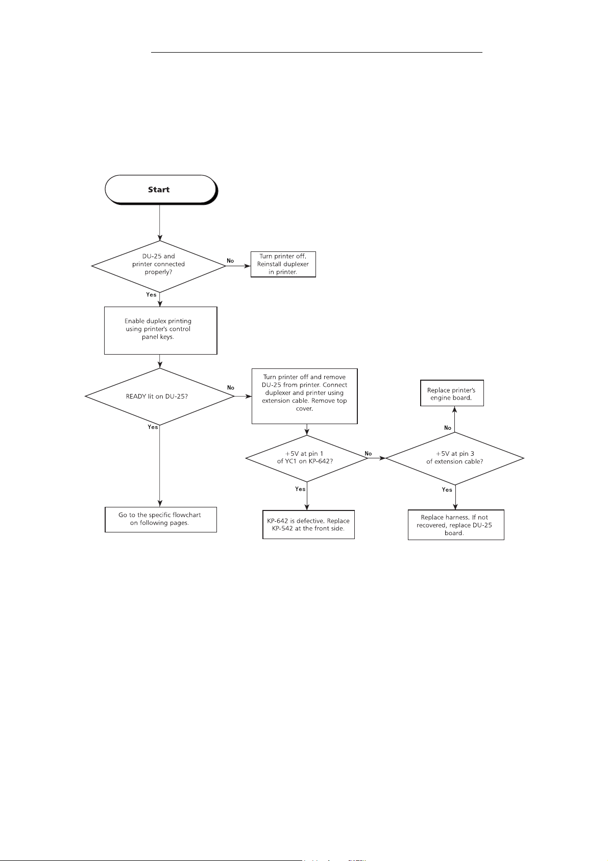
5.2.1. Basic check
The flow chart below is used to check the power lines and communication lines in the
duplexer. This check must be conducted with the duplexer installed with the printer.
Basic check
5-5 DU-25
Page 6
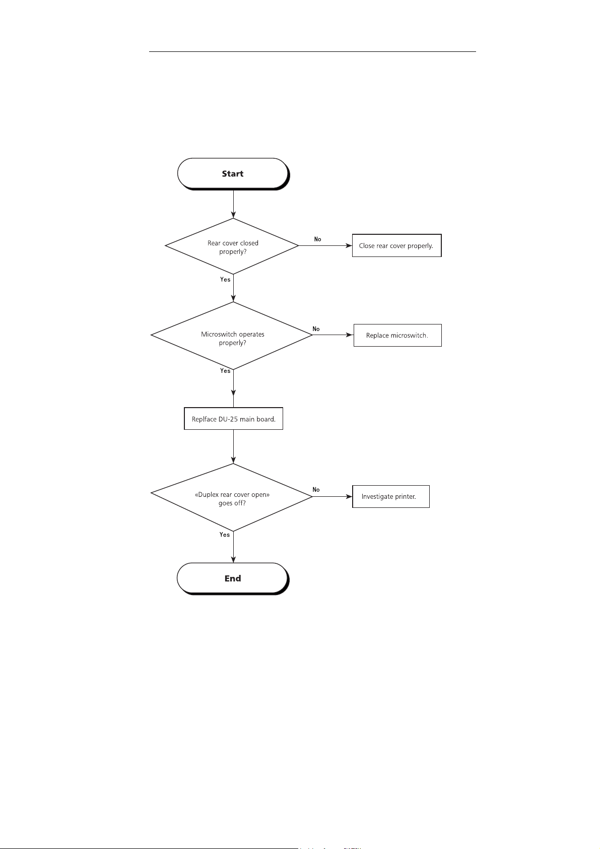
5.2.2. “Duplex unit rear cover open” does not go off
The rear cover status is monitored by a microswitch at the rear of the DU-25. Investigate
this microswitch following the procedures below.
Cover open message does not go off
5-6 DU-25
Page 7

5.2.3. Feed motor does not rotate
If the feed motor does not rotate, paper jam occurs. Investigate the motor power supply
using the following procedures.
Feed motor does not rotate
5-7 DU-25
Page 8

5.2.4. Paper detection sensor
The duplexer uses two sensors for detecting paper transportation. Failure of either sensor can cause paper jam. To investigate the failure of these sensors, start investigation on
sensor 1, then 2 using the same manner as for sensor 1.
Investigating failure on paper detection sensor 1
Using the same procedures above, investigate the operation of sensor 2 on the reversing
bay unit. In doing so, use pin 18 of CN2 for pin 2 of CN4 on KP-639; and use pin 20 of
CN2 on for pin 3 of CN4 on KP-639.
5-8 DU-25
Page 9

5.2.5. Reversing sensor
The reversing sensor (STSEN2) in the reversing bay detects presence of paper in the
reversing bay. If failure is suspected with this sensor, use the following procedures for
investigation.
Investigating failure on reversing bay sensor
5-9 DU-25
Page 10

5.2.6. Reversing bay paper sensor
Reversing bay paper sensor (STSEN1) detects paper entering the reversing bay. Failure
on this sensor can cause paper jam.
Reversing sensor
5-10 DU-25
Page 11

5.2.7. +24V line check
Following the procedures below allows investigation in the +24V power line in the
duplexer. For the +5V line, refer to Basic check.
+24V check
5-11 DU-25
Page 12

5.2.8. Duplexer error messages
The printer continuously monitors the status of the duplexer. In case of an error, it indicates an error code comprising a C and a number correponding to the location of the
error. The error code is succeeded by the message
Call service person
.
The error code(s) pertaining to the duplexer is as tabled below. Other error codes are
detailed in the printer’s service documentation.
Duplexer error(s)
Table 5.1. Duplexer error message
Error Meaning Suggested cause Corrective action
C1 The DU-25 cannot establish
communication with the
printer’s engine CPU.
The DU-25 main board or the
printer’s engine board is
defective. The option interface
connector is defective.
Follow procedure on Basic check
to isolate the location of failure.
5-12 DU-25
Page 13

5.3. Mechanical component
This section provides procedures for isolating paper jams or paper skew. These failures
can typically occur due to the faulty components.
5-13 DU-25
Page 14

5.3.1. Skew feed
If printer ejects paper in a skewed direction only when the duplexer is installed in it, follow the flowchart below. This will allow determine whether the paper is skewed because of
the duplexer or the printer.
Skew feed
5-14 DU-25
Page 15

5-15 DU-25
Page 16

5.3.2. Paper jam
The flowchart below should be used to determine the location of paper jam. For actual
actions to be taken for correction, refer to the sections that follow this diagram.
Paper jam
Hints on r em oving paper ja m
Bliking READYindicator on the DU-25 can mean one of the following possibilities:
Paper was not fed into the duplexer at all since printing has started.
•
Paper jam has occurred inside the duplexer.
•
The duplexer does not feed back the page into the printer.
•
Paper jam was detected at the moment the printer is powered up.
•
The following sections explain how to react these causes for the indication of paper jam.
In these, also refer to the for the location of sensors and motors.
5-16 DU-25
Page 17

Paper was not fed into the duplexer at all since printing has started.
Paper was not fed into the duplexer at all since printing has started.
Paper was not fed into the duplexer at all since printing has started.Paper was not fed into the duplexer at all since printing has started.
The duplexer recognizes that the paper is not present when the feed sensor does not find
paper See table below.
Table 5.1. Jam in the feed unit
Location of
paper jam
Feed unit (rear
end)
Printer and DU-25 are
not properly aligned with
Symptom Possible cause Corrective action
each other due to improper
installation.
Paper jam has occurred inside the duplexer.
Paper jam has occurred inside the duplexer.
Paper jam has occurred inside the duplexer.Paper jam has occurred inside the duplexer.
Paper jam is assumed when sensors SW1 and SW2 are not able to detect the presence of
paper.
Table 5.2. Jam in the duplexer
Location of
paper jam
Symptom Possible cause Corrective action
SW1, SW2 The leading edges of paper
are stuck at the entrance.
SW3 (Reversing
unit gate)
Paper hits the feed roller
(dia. 30 mm) at a perpendicular angle.
Printer is not installed
properly.
Rear feed guide is not
properly seated.
Remove the printer, then
install the printer properly.
Seat the rear feed guide
properly.
Feed unit is defective. Clean rollers; and invbesti-
gate guides.
Front feed guide is defec-
Replface front feed guide.
tive.
SW4 (Reversing
unitÅj
Location of
paper jam
Paper path adaptor
Feed roller (ɔ30) contaminated.
Motor revolves but does
not feed back paper.
Feed roller (ɔ30) is contaminated.
Reversing mylar piece is
defective.
The duplexer does not feed back the page into the printer.
The duplexer does not feed back the page into the printer.
The duplexer does not feed back the page into the printer.The duplexer does not feed back the page into the printer.
Table 5.3. Duplexer does not feed back the page
Symptom Possible cause Corrective action
Paper is stuck at the
duplex inlet.
Paper path adaptor is not
properly installed.
Clean feed roller using alcohol.
Clean feed roller using
alcohl.
Replace reversing mylar
piece.
Remove the paper path
adaptor; then install it again
properly.
5-17 DU-25
 Loading...