

Kyocera DU-20, DU-21 OPTIONS

Chapter 5 Electrical operation
Contents
5.1. Introduction, 5-2
5.2. Interfacing to the printer, 5-3
5.2.1. Connector configuration, 5-3
5.2.2. Duplexer CPU I/O, 5- 4
5.2.3. Sensors, 5-5
5.3. Motor and solenoid drivers, 5-8
5.3.1. Registration motor driver and clutch/locking sole noid driver, 5-8
5.3.2. Transportati on motor drive, 5-8
2-1

5.1. Introduction
This chapter explains the operation of the electrical circuits in the duplexer.
Procedures for hardware troubleshooting are also included in this chapter.
Schematic diagrams are provided in Appendix. The schematic diagram
should be referred to along with the explanation in the following pages.
The electrical circuits of the duplexer are mounted on three boards of main,
display, and rear-switch. For the easy understanding, we explain the
duplexer electrical system dividing it into the following tw o block s:
• Printer interface block
• Driver block
Details on each block will be discussed on the following pages.
2-2
5.2. Interf acing to the printer
This section provides information regarding the duplexer’s interface to the
printer. Basic operation of the interface used in the duplexer resembles that
of the option sorter, paper feeder, etc.
Simplified interface circuit diagram is shown in Figure 5.2. on next page.
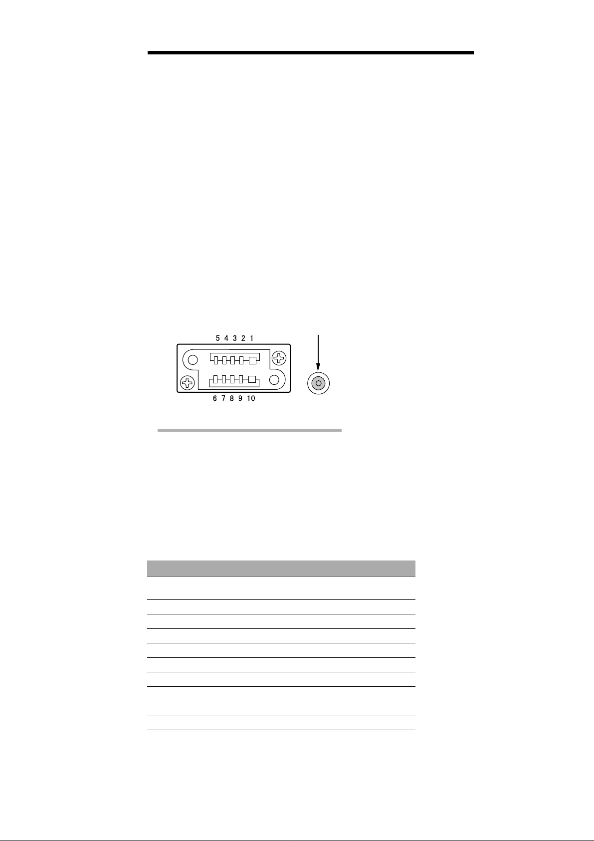
5.2.1. Connector configuration
The duplexer and the printer exchange signals between each other through
connector CN100 which is mounted on top of th e dupl ex er. CN100 is paralleled to CN101 on the other (bottom) side of the duplexer for connection with
the sorter (if installed together with the duplexer to the printer ).
Positioning pin
Left side of the duplexer
The names and the descriptions of the I/O signals handled by the duplexer
are as follows.
Table 1. I/O signals
Pin no. Signal Description
1+24V(IN)
SENS(OUT)
2 SCKD serial clock
3+5V +5V supply
4 READY Handshake
5 SEL0 Select bit 0
6 SEL1 Select bit 1
7 SEL2 Select bit 2
8 SID DU-20 output data
9 SOD DU-20 output data
10 GND Ground
IN: +24V supply
OUT: Feed sensor input to DU-20
2-3
 Loading...